optical surveying and mapping in experimental hydraulics€¦ · · 2005-09-01optical surveying...
TRANSCRIPT

1
Paper N0: II.11
Optical Surveying and Mapping in Experimental Hydraulics
Georg Schuster, Cedomil Josip Jugovic, Hans-Peter Nachtnebel Abstract: By an investigation of the sediment deposition and formation of deltas in reservoirs at the IWHW, Vienna, a new optical surveying and mapping method, the Moiré projection, has been successfully applied. This simple method allows a quick 3-D survey of the model surface. Keywords: Moirè methode, experimental hydraulics, delta
1. Introduction
In the experimental hydraulics one of the main tasks is to map the surface alterations by the simulated processes of deposition, erosion etc. The classical, mechanical methods are depth pointer gauges, woollen threads and photogrammetry. Mechanical methods have the disadvantage, that they are invasive and time consuming.
On the contrary, optical methods are non-invasive because functioning without disturbance of the water surface. They are also more efficient, because they allow at least partly some automatisation of the processes and less time for the measurement. Thus, also by longer acquisition process, if is even possible to operate without personnel. Decision, which method is the optimal one for a specific task, may be brought respective the following criteria:
• Measurement accuracy • Time demand for measurement • Effectiveness • Quality of the surface to be measured (colour, texture, reflection, form, size) • Existing means • Measurement during the tests • Measurement under water

Schuster, Jugovic, Nachtnebel
178
2. Methods for optical surveying of solid surfaces in experimentalhydraulics
By the optical measurement methods, we may differ between single point measurements and image and image interpretation. Single point measurements are mostly very accurate, delivering numerical results, which may be visualised by expert programs, for example Surfer. These processes are often very slow and do not function simultaneously with the tests. Image interpretation is based on photography. Thus, perspective projection may result with distorted photos. Acquisition works mostly quickly. Nevertheless, a processing is needed. The result can be in form of a photo, graphics and/or 3-D co-ordinates.
2.1 Single-point measurement The single-point measuring methods run automated. A laser ray measures the level of the predetermined position. It is mostly reasonable to place the measuring points as a raster and to add the borders and extreme points, if possible. Measuring facility is mostly computer driven. Simple systems project a point by a laser orthogonal to the measuring surface. A side positioned camera records the point position and thus is the level determined.
Figure 1 Schematic of a laser scanner
The hydraulic experimental field (HEF) at the IWHW is a multifunctional, computer driven measuring facility (Nachtnebel et. al, 1997). Thus, is it possible to record the level of the chosen position by a laser distance sensor, resulting with a file with 3-d co-ordinates of the measured points. They can be visualised for example by Surfer.

Optical Surveying and Mapping in experimental Hydraulics 179
Figure 2 Result of the measuring system of the hydraulic engineering experimentation field
2.2 Image Interpretation Image interpretation methods are photogrametry and Moirè topography. Here are the photos made that are later being processed. Nevertheless, by this process distortion appears. Firstly, the camera recording includes a central perspective projection. This leads to a spatial distortion. Through orthogonal exposure may the distortion be diminished, yet not eliminated. By orthogonal recording comes to displacements of measuring points positioned on different levels. This is the result of the difference between the perspective an orthographic projection. These distortions may be compensated easily by adequate methods.
Figure 3 Projective rays of perspective and orthographic projection
2.2.1 Photogrammetry By this method the measured object is being photographed from different angles. Nowadays, no special metric camera for this task is needed. The objective distortion may be calculated and corrected by the known control points. Yet, the camera position does not be known. Nevertheless, the control point’s positions have to be already known. Having just two
Schuster, Jugovic, Nachtnebel
180
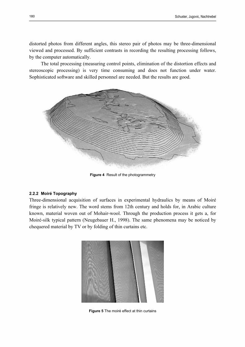
distorted photos from different angles, this stereo pair of photos may be three-dimensional viewed and processed. By sufficient contrasts in recording the resulting processing follows, by the computer automatically.
The total processing (measuring control points, elimination of the distortion effects and stereoscopic processing) is very time consuming and does not function under water. Sophisticated software and skilled personnel are needed. But the results are good.
Figure 4 Result of the photogrammetry
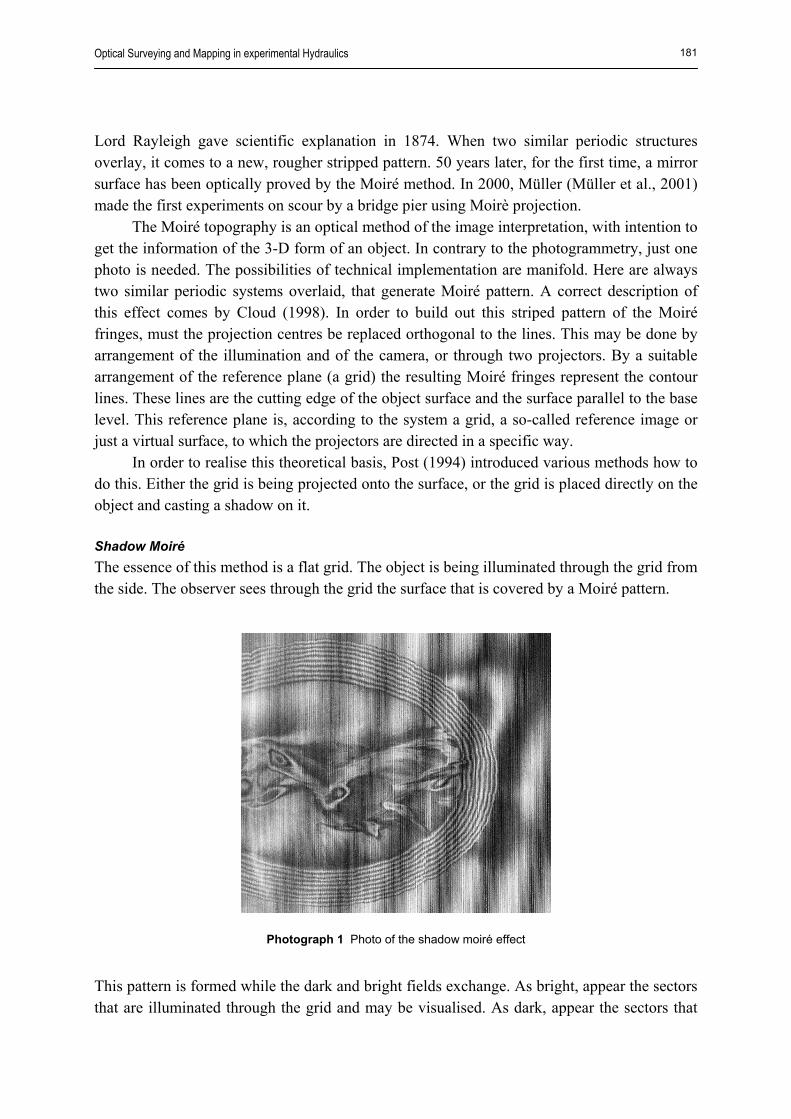
2.2.2 Moiré Topography Three-dimensional acquisition of surfaces in experimental hydraulics by means of Moiré fringe is relatively new. The word stems from 12th century and holds for, in Arabic culture known, material woven out of Mohair-wool. Through the production process it gets a, for Moiré-silk typical pattern (Neugebauer H., 1998). The same phenomena may be noticed by chequered material by TV or by folding of thin curtains etc.
Figure 5 The moiré effect at thin curtains
Optical Surveying and Mapping in experimental Hydraulics 181
Lord Rayleigh gave scientific explanation in 1874. When two similar periodic structures overlay, it comes to a new, rougher stripped pattern. 50 years later, for the first time, a mirror surface has been optically proved by the Moiré method. In 2000, Müller (Müller et al., 2001) made the first experiments on scour by a bridge pier using Moirè projection.
The Moiré topography is an optical method of the image interpretation, with intention to get the information of the 3-D form of an object. In contrary to the photogrammetry, just one photo is needed. The possibilities of technical implementation are manifold. Here are always two similar periodic systems overlaid, that generate Moiré pattern. A correct description of this effect comes by Cloud (1998). In order to build out this striped pattern of the Moiré fringes, must the projection centres be replaced orthogonal to the lines. This may be done by arrangement of the illumination and of the camera, or through two projectors. By a suitable arrangement of the reference plane (a grid) the resulting Moiré fringes represent the contour lines. These lines are the cutting edge of the object surface and the surface parallel to the base level. This reference plane is, according to the system a grid, a so-called reference image or just a virtual surface, to which the projectors are directed in a specific way.
In order to realise this theoretical basis, Post (1994) introduced various methods how to do this. Either the grid is being projected onto the surface, or the grid is placed directly on the object and casting a shadow on it. Shadow Moiré The essence of this method is a flat grid. The object is being illuminated through the grid from the side. The observer sees through the grid the surface that is covered by a Moiré pattern.
Photograph 1 Photo of the shadow moiré effect
This pattern is formed while the dark and bright fields exchange. As bright, appear the sectors that are illuminated through the grid and may be visualised. As dark, appear the sectors that

Schuster, Jugovic, Nachtnebel
182
are either not illuminated, or are covered by the grid. Whether a field is dark or bright may depend, by a constant position of the observer, camera and light source only on the distance of the object surface from the grid (the reference plane).
Figure 6 Principle of the shadow Moiré method
The Moiré fringes are actually layers. They are cutting edges between object surface and the planes parallel to the grid. The level difference between the neighbouring may be determined by the following equation:
isoh∆
αtanS
DSLhiso =⋅
=∆
Where L is the vertical distance between the light source and the camera from the grid, S the
reference grating pitch and D is the distance between the camera and the light source. α is the angle between the observer and the light source.
Projection Moiré The grid projection method is the fringe pattern by one or two projectors, projecting lines to the object. So, is the time consuming building up of the grid unnecessary. Yet, by the grid projection method, it is not possible to produce such a high resolution and such a contrast, as by the grid shadow method.
One Projector Moiré By this method a stripped pattern is projected on the object. In order to generate the Moiré fringes the double-expose is needed: once without the object and secondly with the object. The two pictures are being superpositoned. The reference plane represents the grid and the layers are parallel with it. The geometrical relations are the same as by the grid shadow

Optical Surveying and Mapping in experimental Hydraulics 183
method and thus are also the elevation difference between the layers equal to those by the grid shadow method.
Figure 7 One projector - Schematic of double-exposure projection Moiré
After the superposition of the pictures with object and the one without (reference plane) result is the Moiré pattern.
Photograph 2 Photo of one projector Moiré

Schuster, Jugovic, Nachtnebel
184
Two Projector Moiré It is also possible to use two projectors, where the Moiré lines are, like by grid shadow method, immediately visible. By this method the two projectors are situated in such a way, that their projection axes form an isosceles triangle. The projectors are adjusted to a (virtual) reference plane in such a way, that their line pattern overlap exactly in this plane.
Figure 8 Principle of the two-projector Moiré method
2.2 Measurement under water Measurement under water, during the test performance, has not been possible till now, by optical methods, although such a permanent monitoring would be of a great value. The methods of the single point measurement do not reach the object under water, because the laser ray reflects on the water surface. Besides, these methods are, due to their time consume, unsuitable for the current measurements. Photogrammetric processing is due to the light reflection not possible. Just by the help of the Moiré topography is a continuos monitoring of an ongoing current investigation under water surface possible. Yet, the consequences of the light refraction have to be considered.
Figure 9. Principle of refraction

Optical Surveying and Mapping in experimental Hydraulics 185
Through the light refraction on the water surface, the elevation difference between the Moiré lines is larger, what results with a smaller number of layers. The new distance between the Moiré lines may be easily calculated while taking into account refraction angle δ :
( )δα −=∆
tanShiso
The distortion effect caused by the refraction may be compensated parallel with the spatial perspective equalisation.
3. Summary
Optical methods of the surface acquisition in the experimental hydraulics are absolutely non-invasive and allow a quick recording of the surface. Although extrem time consuming, the single point measurements are in the same time very efficient, because they follow fully automated. Here, especially the Moiré topography should be stressed. By this simple method, it is possible to record very quickly 3-dimensionaly the whole surface of an object. The measurement may follow relatively independently from the surface and the result may be visualised immediately. Above all, the surface recording during the test performance without any disturbance of the tests is unique and promising. The performance may be “live” followed and documented.
References Cloud, G., (1998): Optical Methods of Engineering Analysis, 2. Auflage, Cambridge University Press, Cambridge Müller, G., et al. (2001): Mapping of bridge pier scour with projection Moiré, Journal of hydraulic research Vol. 39,
Madrid Neugebauer, H., Windischbauer, G. (1998): 3D – Fotos alter Meistergeigen, Verlag Erwin Bochinsky GmbH & Co.
KG, Frankfurt am Main Nachtnebel, H.P., Jugovic, C.J., Pölzl, J., (1997): Entwicklungstendenzen im wasserbaulichen Modellversuch,
Wasserbau – Visionen für das nächste Jahrtausend, IWI, Universität Innsbruck Post, D., Han, B., Ifju, P., (1994): High Sensitivity Moiré, Springer-Verlag, New York Inc., New York Authors cand. Eng. Georg Schuster Assoc. Prof. Dr. Cedomil Josip Jugovic Univ. Prof. Dr. Hans-Peter Nachtnebel University of Natural Resources and Applied Life Sciences, Vienna, Austria Institute of Water Management, Hydrology and Hydraulic Engineering – IWHW
