utilities of the future energy findings · pdf fileutilities of the future energy ... that...
TRANSCRIPT

Utilities of the Future Energy Findings
Water Environment Research Foundation635 Slaters Lane, Suite G-110 n Alexandria, VA 22314-1177
Phone: 571-384-2100 n Fax: 703-299-0742 n Email: [email protected]
WERF Stock No. ENER6C13
May 2014
Co-published by
IWA PublishingAlliance House, 12 Caxton StreetLondon SW1H 0QSUnited KingdomPhone: +44 (0)20 7654 5500Fax: +44 (0)20 7654 5555Email: [email protected]: www.iwapublishing.comIWAP ISBN: 978-1-78040-680-0/1-78040-680-0
Co-published by
Utilities of the FutureEnergy Findings
Energy
ENER6C13_WEF-IWAPspread.qxd 4/23/2014 8:27 AM Page 1

UTILITIES OF THE FUTURE ENERGY FINDINGS
by:
Steve Tarallo, ENV-SP Black & Veatch
2014
ENER6C13

ii
The Water Environment Research Foundation, a not-for-profit organization, funds and manages water quality research for its subscribers through a diverse public-private partnership between municipal utilities, corporations, academia, industry, and the federal government. WERF subscribers include municipal and regional water and water resource recovery facilities, industrial corporations, environmental engineering firms, and others that share a commitment to cost-effective water quality solutions. WERF is dedicated to advancing science and technology addressing water quality issues as they impact water resources, the atmosphere, the lands, and quality of life.
For more information, contact: Water Environment Research Foundation 635 Slaters Lane, Suite G-110 Alexandria, VA 22314-1177 Tel: (571) 384-2100 Fax: (703) 299-0742 www.werf.org [email protected] This report was co-published by the following organizations. IWA Publishing Alliance House, 12 Caxton Street London SW1H 0QS, United Kingdom Tel: +44 (0) 20 7654 5500 Fax: +44 (0) 20 7654 5555 www.iwapublishing.com [email protected] © Copyright 2014 by the Water Environment Research Foundation. All rights reserved. Permission to copy must be obtained from the Water Environment Research Foundation. Library of Congress Catalog Card Number: 2014935575 Printed in the United States of America IWAP ISBN: 978-1-78040-680-0/1-78040-680-0 This report was prepared by the organization(s) named below as an account of work sponsored by the Water Environment Research Foundation (WERF). Neither WERF, members of WERF, the organization(s) named below, nor any person acting on their behalf: (a) makes any warranty, express or implied, with respect to the use of any information, apparatus, method, or process disclosed in this report or that such use may not infringe on privately owned rights; or (b) assumes any liabilities with respect to the use of, or for damages resulting from the use of, any information, apparatus, method, or process disclosed in this report. Black & Veatch This document was reviewed by a panel of independent experts selected by WERF. Mention of trade names or commercial products or services does not constitute endorsement or recommendations for use. Similarly, omission of products or trade names indicates nothing concerning WERF's positions regarding product effectiveness or applicability.

Utilities of the Future Energy Findings iii
In 2013, the National Association of Clean Water Agencies (NACWA), the Water
Environment Research Foundation (WERF), and the Water Environment Federation (WEF) released the report: Water Resources Utility of the Future . . . Blueprint for Action. Wherever possible these three organizations are working together to support the development of Utilities of the Future. One key objective is to ensure a sustainable future for the clean water sector by minimizing waste and maximizing resources, including energy. This report builds upon this principle and provides the supporting data and methodology that drive the potential for energy efficiency and recovery.
This report must be read in conjunction with the WERF research report Net-Zero Energy Solutions for Water Resource Recovery Facilities (WERF ENER1C12, 2015). While this Utilities of the Future Energy analysis report was prepared under the management of Steve Tarallo, P.E., Black & Veatch, much of the information and energy models stem from the Net-Zero project. In addition to Black and Veatch, AECOM and Philadelphia Water Department along with their teams who contributed greatly to the Net-Zero report, are acknowledged. The report would not be possible without their effort. Research Team
Principal Investigator: Steve Tarallo, ENV-SP Black & Veatch
Project Team:
Alok Patil Christine Polo, E.I.T Andrew Shaw, P.E. Black & Veatch
Technical Advisory Committee: Randy Benn, Esq. Claudio Ternieden, J.D. Barry Liner, Ph.D., P.E. WEF Cynthia Finley, Ph.D. Pat Sinicropi, J.D. NACWA
Water Environment Research Foundation Staff Director of Research: Amit Pramanik, Ph.D., BCEEM Senior Program Director: Lauren Fillmore, M.S.
ACKNOWLEDGMENTS

iv
Abstract:
The findings of this research were developed to inform decision making on renewable energy embedded in domestic wastewater and the potential to recover this resource. Researchers used the energy balances for water resource recovery facilities (WRRFs) generated under WERF study ENER1C12 to develop national energy projections. This report is one of several in the WERF energy portfolio. It estimates the energy embedded in wastewater, characterizes it, and estimates costs and savings associated with moving WRRFs to become energy neutral or even energy positive. Benefits:
Substantiates the finding that there is five times the energy currently required for treatment of domestic wastewater nationwide available in the wastewater sector.
Calculates that maximizing the overall energy reduction for the largest 100 WRRFs in the U.S is a cost competitive option with other renewable energy (such as wind and solar).
Demonstrates why sequencing and synchronizing the nitrogen limiting permit cycle with the advancement and implementation of short-cut nitrogen removal technologies may be the best investment in water quality improvement.
Keywords: Energy-neutral, renewable energy, thermal energy.
ABSTRACT AND BENEFITS

Utilities of the Future Energy Findings v
Acknowledgments.......................................................................................................................... iii Abstract and Benefits ..................................................................................................................... iv List of Tables ................................................................................................................................. vi List of Figures ............................................................................................................................... vii List of Acronyms ......................................................................................................................... viii Glossary of Power, Energy, and Heat Terms ...................................................................................x Conversion Table .............................................................................................................................x Executive Summary ...................................................................................................................ES-1 1.0 Introduction .................................................................................................................... 1-1 1.1 Background .......................................................................................................... 1-1 1.2 Research Approach .............................................................................................. 1-1 2.0 Treatment Process Distribution at Water Resource Recovery
Facilities in the U.S. ....................................................................................................... 2-1 3.0 U.S. Wastewater Sector Energy Use ............................................................................ 3-1
4.0 Available Energy in the U.S. Wastewater Sector ........................................................ 4-1 5.0 Technology Pathways to Energy Neutral WRRFs ...................................................... 5-1 6.0 Nitrogen-Energy Nexus ................................................................................................. 6-1 7.0 Levelized Cost of Energy for Energy-Neutral Water
Resource Recovery Facilities ........................................................................................ 7-1 7.1 Methodology ........................................................................................................ 7-1 7.2 General Assumptions and Scenario Analysis ...................................................... 7-2 7.3 LCOE Results ...................................................................................................... 7-3 7.4 Energy Investment in WRRFs ........................................................................... 7-10 8.0 Thermal Energy Recovery ............................................................................................ 8-1 8.1 Levelized Cost of Energy (LCOE) ...................................................................... 8-3
9.0 Conclusions ..................................................................................................................... 9-1 9.1 Recommendations ................................................................................................ 9-2 Appendix A ................................................................................................................................. A-1 Appendix B ..................................................................................................................................B-1 Appendix C ..................................................................................................................................C-1 Appendix D ................................................................................................................................. D-1 References ....................................................................................................................................R-1
TABLE OF CONTENTS

vi
2-1 Main Liquid Stream Treatment Process Distribution ...................................................... 2-2 2-2 Solids Process Distribution .............................................................................................. 2-3 3-1 Main Liquid Stream Process Configurations Matched to WERF ENER1C12 Baseline Configurations ................................................................................................... 3-1 3-2 Solids Process Configurations Matched to WERF ENER1C12 Baseline Configurations ................................................................................................... 3-2 3-3 Energy Use in the U.S. Wastewater Sector (Large Facilities > 5 mgd) .......................... 3-3 3-4 Projected U.S. Wastewater Sector Energy Use ............................................................... 3-4 3-5 U.S. Wastewater Sector Contribution to U.S. Electricity Demand ................................. 3-4 4-1 Total Available Energy in the U.S. Wastewater Sector (Large Facilities > 5mgd) ......... 4-1 5-1 Energy Saving and Energy Recovery Technologies ........................................................ 5-2 5-2 Main Liquid Stream Treatment Modifications to Achieve Energy Neutrality ................ 5-3 5-3 Solids Process Modifications to Achieve Energy Neutrality ........................................... 5-4 5-4 Incineration and Gasification Based on Plant Size .......................................................... 5-4 5-5 Energy Savings from 492 Energy Neutral WRRFs ......................................................... 5-5
6-1 Modeled Net Energy Recovery Potential Available in Different Process Configurations for Nitrogen Control ............................................................................... 6-2
7-1 100 Largest Facilities Unit Cost Comparisons for Electrical Energy Savings ................ 7-1 7-2 LCOE Cost Assumptions .................................................................................................. 7-2 7-3 LCOE Analysis Scenario Assumptions – Energy Neutral WRRFs ................................. 7-3 7-4 LCOE Comparisons for Electrical Energy Savings ......................................................... 7-6 7-5 LCOE Comparisons for Primary Energy Savings ........................................................... 7-6 7-6 Lifetime Energy Reduction and Associated Cost .......................................................... 7-10 7-7 100 Energy Neutral Facilities LCOE Comparisons for Electric Energy Savings ......... 7-11 7-8 100 Largest Facilities LCOE Comparisons for Electric Energy Savings ...................... 7-11
8-1 Characteristics of Cities Selected for Estimating Thermal Energy Recovery Using Wastewater Source Heat Pumps ...................................................................................... 8-1 8-2 Estimated Thermal Energy Recoverable from Wastewater of 17 Major U.S. Cities ...... 8-2 8-3 LCOE Assumptions ......................................................................................................... 8-3 8-4 Comparison of LCOE to Retail Gas Rates and Energy Efficiency Projects .................... 8-5
LIST OF TABLES

Utilities of the Future Energy Findings vii
6-1 Typical Electric Power Demand for Various Levels of Wastewater Treatment Necessary to Meet Nutrient Limited and Advanced Discharge Permits (from ENER1C12) ........... 6-2
6-2 Energy and Carbon Demand Comparison for Nitrogen Removal Using Deammonification and Conventional Nitrification/Denitrification ................................. 6-3
7-1 Cumulative Electric Energy Savings for Converting 492 Large WRRFs to Energy Neutral Over 50-Year Time Frame. ................................................................ 7-4 7-2 Cumulative Primary Energy Savings for Converting 492 Large WRRFs to Energy Neutral Over 50-Year Time Frame. ................................................................ 7-4
7-3 Capital Costs for Converting 492 Large WRRFs to Energy Neutral Over 20-Year Technology Roll Out, Design, and Construction Time Frame. ................ 7-5 7-4 LCOE Comparison Chart for Electrical Energy Savings – Energy Generation Technologies ..................................................................................... 7-7 7-5 LCOE Comparison Chart for Primary Energy Savings – Energy Generation Technologies ..................................................................................... 7-7 7-6 Frequency Distribution for Electrical Energy Savings .................................................... 7-9 7-7 Frequency Distribution for Primary Energy Savings....................................................... 7-9 7-8 LCOE Comparison Chart for 100 Energy Neutral WRRF Electrical Energy Savings versus Commercial Rates and Demand Response Programs ......................................... 7-12 7-9 LCOE Comparison Chart for Largest 100 WRRF Electrical Energy Savings versus Commercial Rates and Demand Response Programs. ........................................ 7-12 8-1 Cumulative Primary Energy Savings from Thermal Energy Recovery Using Wastewater Source Heat Pumps ...................................................................................... 8-4 8-2 Capital Costs for Thermal Energy Recovery Using Wastewater Source Heat Pumps .... 8-4 8-3 Comparison of LCOE to Retail Gas Resources ............................................................... 8-5 C-1 Secondary Treatment Only with AD (applied to plants >20 mgd). .....................................C-1 C-2 SNR with AD (applied at plants <20 mgd) ......................................................................C-2 C-3 Secondary Treatment with AD and Gasification (applied at plants 20-50 mgd) .............C-2 C-4 SNR with AD and Gasification (applied at plants 20-50 mgd) .......................................C-3 C-5 Secondary Treatment with AD and Incineration (applied at plants >50 mgd) ................C-3 C-6 SNR with AD and Incineration (applied at plants >50 mgd) ..........................................C-4 C-7 Secondary Treatment with Incineration (applied to plants already with incineration) .........C-4 C-8 SNR with Incineration (applied to plants already with incineration) ....................................C-5
LIST OF FIGURES
viii
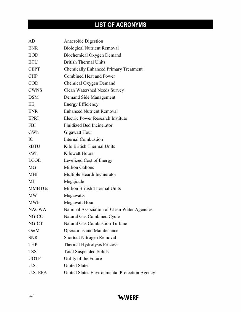
AD Anaerobic Digestion BNR Biological Nutrient Removal BOD Biochemical Oxygen Demand BTU British Thermal Units CEPT Chemically Enhanced Primary Treatment CHP Combined Heat and Power COD Chemical Oxygen Demand CWNS Clean Watershed Needs Survey DSM Demand Side Management EE Energy Efficiency ENR Enhanced Nutrient Removal EPRI Electric Power Research Institute FBI Fluidized Bed Incinerator GWh Gigawatt Hour IC Internal Combustion kBTU Kilo British Thermal Units kWh Kilowatt Hours LCOE Levelized Cost of Energy MG Million Gallons MHI Multiple Hearth Incinerator MJ Megajoule MMBTUs Million British Thermal Units MW Megawatts MWh Megawatt Hour NACWA National Association of Clean Water Agencies NG-CC Natural Gas Combined Cycle NG-CT Natural Gas Combustion Turbine O&M Operations and Maintenance SNR Shortcut Nitrogen Removal THP Thermal Hydrolysis Process TSS Total Suspended Solids UOTF Utility of the Future U.S. United States U.S. EPA United States Environmental Protection Agency
LIST OF ACRONYMS

Utilities of the Future Energy Findings ix
W Watt WHRB Waste Heat Recovery Boiler WEF Water Environment Federation WERF Water Environment Research Foundation WRRF Water Resource Recovery Facility

x
British Thermal Unit (BTU) The BTU is the unit of energy needed to cool or heat one pound
of water by 1° Fahrenheit. District heating System for distributing heat generated in a centralized location
for residential and commercial heating or hot water in a neighborhood district.
Giga One billion. Joule The work required to produce one watt of power for one
second; equivalent to one 3600th of a watt-hour. Kilo One thousand. Mega One million. Natural Gas Combined Cycles (NG-CC)
An electricity producing technology that creates electricity from natural gas by using combustion turbines while routing the hot exhaust to a convention boiler for traditional steam turbine utilization. This process of capturing otherwise lost heat achieves efficiency of about 60%.
Natural Gas Combustion Turbine (NG-CT)
A type of internal combustion (IC) engine that creates electricity from natural gas. Gas is mixed with air and ignited in a chamber where the combustion exhaust enters a turbine with shafts that generate electric power. Achieves an efficiency of about 40%.
Primary energy Energy in the form found in nature (includes coal, methane gas) that has not been subjected to any conversion or transformation process (such as turned into electricity).
Watt (W) A unit of power named after James Watt. Power is the rate at which energy is consumed or produced.
Watt-hour A measure of electrical energy equivalent to a power consumption of one watt for one hour.
Convert Units To Units Equals
Terawatt (TW) 1 Gigawatt (GW) 1,000 GW
Gigawatt (GW) 1 Megawatt (MW) 1,000 MW
Megawatt (MW) 1 Kilowatt (kW) 1,000 kW
Kilowatt (KW) 1 Watt (W) 1,000 W
Kilowatt hour (kWh) 1 British Thermal Unit (BTU) 3412 BTU
British Thermal Unit (BTU) 1 Joules 1055 Joules
CONVERSION TABLE
GLOSSARY OF POWER, ENERGY, AND HEAT TERMS

Utilities of the Future Energy Findings ES-1
EXECUTIVE SUMMARY
In 1996, the Electric Power Research Institute (EPRI) published a report entitled Water and Wastewater Industries: Characteristics and Energy Management Opportunities which described how electricity is used in the water and wastewater treatment sector. In 2013, EPRI updated their study and estimated that the domestic wastewater sector currently uses 30 billion kWh/yr of electric power. Additional studies (Shizas and Bagley, 2004; Wett, Buchauer and Fimml, 2007) provide evidence that there is adequate energy embedded in domestic wastewater to significantly offset the power demand for treatment through energy resource recovery at wastewater facilities. For consistency with the 2013 EPRI study’s methodology, researchers for this study used the United States Environmental Protection Agency’s (U.S. EPA’s) Clean Watershed Needs Survey (CWNS) plant flow and technical process data when available, sorted by treatment facility size. Energy balance and demand data generated under another WERF study (ENER1C12) were used with the CWNS plant flow data to develop national energy projections from the domestic wastewater sector. ENER1C12 project team estimated the energy balance and potential energy savings from large facilities (>5 mgd) becoming energy neutral based on process information using GPS-x models for 25 common water resource recovery facility (WRRF) configurations.
The objectives of this study are to:
Estimate the energy embedded in domestic wastewater in the United States (U.S.) relative to the energy required to accomplish treatment.
Characterize the forms of this energy. Estimate the potential energy savings by facilities that become net energy neutral while
providing the same or better level of treatment. Estimate the cost to convert the facilities with the greatest potential to become energy neutral
over the next 20 years and compare the cost of this energy with other energy sources. Estimate the cost to maximize energy reduction from the 100 largest WRRFs.
Findings
This study estimated the total available energy in the wastewater sector (851 trillion
BTUs/year) as the sum of the chemical, heat, and kinetic energy sources. This is five times the
energy currently required for treatment of domestic wastewater nationwide. 80% of the energy in wastewater is in the form of heat, while 20% is chemical energy. Kinetic (hydraulic) energy is specific to the location of the facility and represents less than 1% of energy in wastewater nationwide.
Maximizing the overall energy reduction for the largest 100 WRRFs in the U.S. is a cost competitive option with other renewable energy (such as wind or solar). It has a nationwide overall lifetime (30 year asset life) reduction of 142 TWh electricity and 1,658 trillion BTUs primary energy.
Electric generation facilities in the U.S. are commonly utility-scale (tens to hundreds of MW facilities) with significant economies of scale, whereas electric power generated by WRRFs represents a distributed, and dispatchable source of energy. Unlike wind and solar, common forms of renewable energy, electric power generated by WRRFs is reliable and can be produced

ES-2
any time of the day or under windless conditions. The sole investment objective for electric utilities is to generate electric power, while the generation of power by WRRFs is secondary to their core mission – to reclaim water quality. However, many of the modifications required for achieving energy reduction at WRRFs also have additional important benefits, such as a reduction in nutrients discharged to waterways, a reduction in the quantity of solids disposed of in landfills, pathogen reduction in biosolids, and nutrient recovery in biosolids to offset the application of synthetic fertilizers. None of the other renewable energy technologies, such as
solar or wind, have such a wide variety of environmental and societal benefits as obtaining
renewable energy from WRRFs.
Approximately 70% of the total electric and primary energy savings from converting large WRRFs to energy neutral can be achieved by focusing on just those 100 WRRFs that can be converted to net-zero at competitive levelized cost of energy (LCOE) of $165 per Megawatt Hour (MWh) and $15 per million BTU.
A large majority (>80%) of the energy contained in wastewater is in the form of
thermal energy. Through the use of distributed wastewater source heat pumps, WRRFs can extract this energy from raw wastewater in the collection and conveyance system and from effluents at facilities, reusing it to supply district (neighborhood-scale) heating to residential and commercial establishments within their respective service areas.
Barriers to recovering thermal energy from wastewater for use include the lack of existing infrastructure to distribute the recovered heat as well as the need for the heating demand to be in close proximity to the heat pump installations in order to minimize heat loss during distribution. Despite these barriers, district heating networks are prevalent in European cities and provide up to 100% of the heating demand in some areas. Smaller networks also exist in the U.S., providing heat to large commercial buildings and university campuses. The recovered thermal energy is a direct substitute for the current widespread use of natural gas or heating oil used for space heating across the U.S.
WRRFs which remove nitrogen recognize the connection between the transformation of nitrogen constituents and energy. Using only currently accepted processes (e.g., Biological Nutrient Reduction (BNR)) for nitrogen conversion from waterborne forms (ammonia, nitrate) to inert nitrogen gas, WRRFs can expect to see a significant increase in energy demand. However, research into emerging processes using recently identified organisms (anammox) has led to the concept of shortcut nitrogen removal (SNR). SNR, particularly for use in mainstream applications, is an innovative approach that uses less energy than current BNR processes. The ability to produce low-nitrogen effluent by using a low-energy process has great potential. However, support for innovation and investment in improved microbial processes is critical to advance significant improvements in the water resource recovery sector. Energy efficient best
practices can reduce 40% of energy demand at WRRFs, but energy neutrality with
nitrogen removal depends upon innovation and the adoption of SNR practices.

Utilities of the Future Energy Findings 1-1
CHAPTER 1.0
INTRODUCTION Many in the water resources sector see the Utility of the Future (UOTF) as a vision where
traditional wastewater utilities transform themselves to facilities that achieve their core mission to produce clean, safe water, while also recovering resources to minimize waste and progress towards sustainability. As a result, they manage their operations more efficiently to recover resources embedded in wastewater that were previously lost or considered waste (WERF3C12). These embedded resources include energy, nutrients, other constituents, and the water itself. This report focuses on the energy resources embedded in domestic wastewater in the U.S.
1.1 Background In 1996, the EPRI published a report entitled Water and Wastewater Industries:
Characteristics and Energy Management Opportunities which described how electricity is used in the water and wastewater treatment sector. In 2013, EPRI updated this study and estimated that the domestic wastewater sector currently uses 30 billion kWh/yr of electric power. Additionally, recent studies (Shizas and Bagley, 2004; Wett, Buchauer, and Fimml, 2007) provide evidence that there is adequate energy embedded in domestic wastewater to significantly offset the power demand for treatment through energy resource recovery at wastewater facilities.
The objectives of this study are to:
Estimate the energy embedded in domestic wastewater in the U.S. relative to the energy required to accomplish treatment.
Characterize the forms of this energy. Estimate the potential energy savings by facilities which become net energy neutral while
providing the same or better level of treatment. Estimate the cost to convert the WRRFs with the greatest potential to become energy neutral
over the next 20 years and compare the cost of this energy with other renewable energy sources.
Estimate the cost to maximize energy reduction from the 100 largest WRRFs.
1.2 Research Approach For consistency with the 2013 EPRI study, researchers in this study used the U.S. EPA’s
CWNS plant flow data sorted by the size of the treatment facility. The 2008 CWNS data show that the largest facilities - those treating 5 mgd or more of the domestic wastewater flow - treat almost 80% of the total treated domestic wastewater in the U.S. Under a related WERF study, Net Zero Energy Solutions for Water Resource Recovery Facilities (ENER1C12), researchers modeled the energy balance of 25 common wastewater treatment configurations in plants over 5 mgd treatment capacity. These modeled balances yield energy demand data and recovery potential that are more representative of actual conditions than generalized energy intensity values used in other studies to estimate the national energy use by the wastewater sector. The research approach is described in detail in the following section.

1-2

Utilities of the Future Energy Findings 2-1
CHAPTER 2.0
TREATMENT PROCESS DISTRIBUTION AT WRRFS IN THE U.S.
This study estimated the potential energy savings by large facilities (>5 mgd) becoming
energy neutral by using process information and flow from the 2008 CWNS and energy balances developed for 25 WRRF configurations as part of the WERF ENER1C12 energy study. By sorting the CWNS database to extract the data on the facilities over 5 mgd, the study identified and matched the main liquid stream and solids processes of significance for the U.S. municipal wastewater sector with process configurations with modeled balances, as shown in Tables 2-1 and 2-2.
The most commonly used main liquid stream treatment processes and solids treatment processes at large facilities account for 80% of total large facility capacity and 62% of total sector capacity. The remainder of this report focuses on these processes at facilities above 5 mgd, analyses of sector energy use, and paths to energy neutrality. Approximately 20% of the CWNS large facility entries, however, provided no information on either the main liquid stream treatment or solids treatment processes, accounting for 4% and 12% of the total sector capacity respectively. Estimates were extrapolated for facilities with no information in the CWNS data.

2-2
Table 2-1. Main Liquid Stream Treatment Process Distribution.
MAIN LIQUID STREAM TREATMENT
NO. OF
FACILITIES
% OF TOTAL
NO. OF FACILITIES
AVG. FLOW CAPACITY
(MGD)
TOTAL FLOW
CAPACITY (MGD)
% OF TOTAL
LARGE FACILITY CAPACITY
MODELED AND USED IN
ANALYSIS
BNR with Primary Treatment 211 20.5% 52 7,426 29% YES
Conv. Act. Sludge with Primary Treatment
225 21.9% 29 6,502 26% YES
Nitrification with Primary Treatment
92 9.0% 21 1,951 8% YES
Mainstream A/B 18 1.8% 89 1,595 6% YES
No Info 173 16.8% 8 1,436 6% YES
Nitrification without Primary Treatment
56 5.5% 23 1,307 5% YES
Enhanced Nutrient Removal (ENR) with Primary Treatment and Chemical P. Removal
43 4.2% 30 1,302 5% YES
Short SRT Step Feed 17 1.7% 52 888 4% NO
No Treatment 114 11.1% 8 874 4% NO
Trickling Filter (TF) 45 4.4% 30 744 3% NO
Primary Only 2 0.2% 131 262 1% NO
BNR with Primary Treatment without Carbon Addition
2 0.2% 37 74 <1% NO
ENR with Primary Treatment 14 1.4% 16 220 <1% NO
Lagoon 10 1.0% 16 156 <1% NO
Membrane Bioreactor (MBR) (Aerobic)
3 0.3% 74 221 <1% NO
Combination of Conv. Act. Sludge, BNR, and TF
1 0.1% 88 88 <1% NO
Combination of Pure Ox. and Trickling Filter
1 0.1% 151 151 0.6% NO
TOTAL Facilities > 5mgd 1,027 7% 24.5 25,197 78% YES
TOTAL Small Facilities <5mgd 13,753 93% 0.52 7,148 22% NO

Utilities of the Future Energy Findings 2-3
Table 2-2. Solids Process Distribution.
SOLIDS PROCESS
NO. OF FACILITIES
% OF TOTAL
NO. OF FACILITIES
AVG. FLOW CAPACITY
(MGD)
TOTAL FLOW
CAPACITY (MGD)
% OF TOTAL
LARGE FACILITY CAPACITY
USED IN ANALYSIS
Anaerobic Digestion (AD) 476 46% 30 14,333 57% YES
No Info 246 24% 15 3,765 15% YES
Dewatering Only 84 8% 29 2,463 10% YES
Aerobic Digestion 58 6% 18 1,042 4% YES
Multiple Hearth Incinerator (MHI)
57 6% 17 997 4% YES
AD and MHI 2 0% 334 668 3% YES
Fluidized Bed Incinerator (FBI)
29 3% 17 484 2% YES
Incineration 16 2% 22 349 1% NO
Thickening Only 24 2% 16 374 1% NO
No Solids Processing 13 1% 15 192 1% NO
AD and Incineration 6 1% 25 148 1% NO
Aerobic Digestion and Composting
1 0% 92 92 0% NO
AD and Heat Drying 1 0% 92 92 0% NO
Lime Stabilization 3 0% 15 45 0% NO
Heat Drying 3 0% 23 69 0% NO
Air Drying 1 0% 11 11 0% NO
Autothermal Thermophilic Aerobic Digestion (ATAD)
2 0% 12 23 0% NO
Composting 5 0% 10 50 0% NO
TOTAL Facilities > 5mgd 1,027 7% 24.5 25,197 78% YES
TOTAL Small Facilities <5mgd
13,753 93% 0.52 7,148 22% NO

2-4

Utilities of the Future Energy Findings 3-1
CHAPTER 3.0
U.S. WASTEWATER SECTOR ENERGY USE The WERF ENER1C12 project involved modeling and developing energy balances for
over 40 different WRRF configurations, including 25 baseline configurations representing typical WRRFs, and 18 “pioneering modules” representing innovative, energy saving technologies. The research team matched the most commonly used main liquid stream and solids process configurations to corresponding baseline configurations from the WERF ENER1C12 study, as shown in Tables 3-1 and 3-2.
The researchers used baseline configurations as a basis for calculating the total power usage of the sector and the pioneering modules as a basis to calculate the potential for energy savings from energy recovery technologies. Energy balance diagrams for the baseline configurations are included in Appendix A.
Table 3-1. Main Liquid Stream Process Configurations Matched to WERF ENER1C12 Baseline Configurations.
MAIN LIQUID STREAM TREATMENT
BASELINE CONFIGURATION FROM
WERF ENER1C12
ELECTRICITY USAGE
(KWH/MG)
PROCESSES INCLUDED
BOD Removal Only with Primary Treatment
B 806 Influent pumping, screening and grit removal, BOD removal only with Primary Treatment, Final Clarifiers
Nitrification without Primary Treatment
E 1,325 Influent pumping, screening and grit removal, Nitrification without Primary Treatment, Final Clarifiers
Nitrification with Primary Treatment
E’ 1,089 Influent pumping, screening and grit removal, Nitrification with Primary Treatment, Final Clarifiers
BNR with Primary Treatment G 1,311 Influent pumping, screening and grit removal, BNR with Primary Treatment, Final Clarifiers
ENR with Primary Treatment and Chemical Phosphorus Removal
M 1,382 Influent pumping, screening and grit removal, ENR with Primary Treatment and Chemical P. removal, Final Clarifiers
Mainstream A/B P 1,454 Influent pumping, screening and grit removal, Mainstream A/B, Final Clarifiers

3-2
Table 3-2. Solids Process Configurations Matched to WERF ENER1C12 Baseline Configurations.
SOLIDS PROCESS
BASELINE CONFIG.
ELECTRICITY USAGE
(KWH/MG)
PROCESSES INCLUDED
Anaerobic Digestion (AD) 1 149 Thickening, AD, Dewatering
Dewatering Only Not generated 27 Thickening, Dewatering
Aerobic Digestion 2 374 Thickening Aerobic Digestion, Dewatering
Multiple Hearth Incinerator (MHI) 5 288 Thickening Dewatering, MHI
Fluidized Bed Incinerator (FBI) 6 159 Thickening, Dewatering, FBI
The electricity and natural gas usages from the baseline configurations were applied to the U.S. municipal wastewater sector to estimate the total energy usage of plants over 5 mgd. Table 3-3 summarizes the energy use of the wastewater sector in terms of electrical intensity (kWh/MG) and primary energy intensity as Kilo British Thermal Units (kBTU/MG). Primary energy is the raw fuel source that is burned or otherwise converted to useful forms of energy, such as heat and electricity.
Results indicate the sector has average energy intensity for the sector of 1,641 kWh/MG and primary energy intensity of 1,196 kBTU/MG. Researchers applied these averages to the WRRFs with no information available to generate a nationwide estimate. These assumptions are conservatively low given that the lack of CWNS information is often from small plants. Smaller facilities typically have higher energy intensities than larger facilities.

Utilities of the Future Energy Findings 3-3
Table 3-3. Energy Use in the U.S. Wastewater Sector.
(Large Facilities > 5 mgd)
PARAMETER
UNITS VALUE
KWH/ MG
KBTU/MG
Number of Plants No. 1,027
Total Capacity MGD 25,197
Main Liquid Stream Treatment Electricity TWh/year 10 1,089
Solids Process Electricity TWh/year 1.6 172
Odor Control and Lighting Electricity TWh/year 3.5 380
Total Electricity Use TWh/year 15.1 1,641
Combined Heat and Power (CHP) Electricity generated
TWh/year 0.5
50
Net Electricity Use TWh/year 14.6 1,590
Electricity Primary Energy* Trillion BTU/year 167 18,158
Total Natural Gas import Trillion BTU/year 11 1,196
Natural Gas Primary Energy* Trillion BTU/year 11.5 1,250
TOTAL PRIMARY ENERGY Trillion BTU/year 178 19,354
*Natural gas and electricity sources of energy converted to equivalent units of raw fuel consumed. To achieve this equivalency, U.S EPA ENERGY STAR® source-site ratios of 3.34 and 1.047 were applied for electricity (grid purchase) and natural gas, respectively. (Ref. U.S. EPA ENERGY STAR®. http://www.energystar.gov/index.cfm?c=evaluate_performance.bus_portfoliomanager)
Electrical and primary energy intensity values of 1,641 kWh/MG and 19,354 kBTU/MG, respectively, from Table 3-3 were applied to the 7,148 mgd of small (<5 mgd) facility capacity to develop estimates of total sector energy use for treatment. Once again, these are conservative assumptions. Energy used for collection and conveyance (e.g., pump stations) of municipal wastewater is highly location specific. According to NACWA energy survey data for approximately 60 larger utilities (NACWA, 2011), energy use for wastewater collection and conveyance contributes an additional 18% to the energy used for treatment. Table 3-4 summarizes wastewater sector total energy use.

3-4
Table 3-4. Projected U.S. Wastewater Sector Energy Use.
ELECTRICAL ENERGY (TWH/YEAR)
% OF TOTAL U.S ELECTRICITY USE
PRIMARY ENERGY (TRILLION BTU/YEAR)
% OF TOTAL U.S PRIMARY ENERGY USE
Treatment 18.9 0.49% 229 0.24%
Collection and Conveyance
3.4 0.09% 41 0.04%
TOTAL 22.3 0.58% 270 0.28%
Table 3-5 demonstrates the significance of the U.S. wastewater sector’s contribution to U.S. electricity use relative to select industrial users.
Table 3-5. U.S. Wastewater Sector Contribution to U.S. Electricity Demand.
1 The estimate of the municipal wastewater sector electricity demand generated in this study (22TWh/year) is slightly less than the 2013 EPRI estimate of 30 TWh/year. Two independent estimates falling within + 25% is reasonable agreement.
Data for other sectors taken from: http//www1.eere.energy.gov/manufacturing/pdfs/energy-use-and-loss-and-emmissions.pdf.
SECTOR
ELECTRICAL ENERGY
(TWh/Year)
% OF TOTAL U.S
ELECTRICITY USE
Chemicals 198 5.1%
Forest Products 142 3.7%
Food and Beverage 86 2.2%
Iron and Steel 63 1.6%
Computers, Electronics, and Electrical Equipment
40 1.0%
Municipal Wastewater1 22 0.6%
Glass 18 0.5%
Foundries 17 0.4%
Cement 13 0.3%

Utilities of the Future Energy Findings 4-1
CHAPTER 4.0
AVAILABLE ENERGY IN THE U.S. WASTEWATER SECTOR
The total available energy in the wastewater sector was estimated as the sum of the
chemical, heat, and kinetic energy sources, as Table 4-1 shows. Given the very large number of small facilities (~15,000) and their unlikely transition to energy neutrality within a reasonable (<20 year) time frame, this study’s analysis of total sector available energy includes only large facilities.
The research team estimated chemical energy potential, assuming that 100% of the chemical energy in the wastewater is recoverable. The chemical oxygen demand (COD) of the influent wastewater represents chemical energy. The calculation is based on a COD of 358 mg/l with an energy content of 5,971 BTU/lb COD (13.8 Megajoule (MJ)/kg COD).
The recoverable heat energy was calculated assuming a change in temperature of 5C across the heat exchange device.
The kinetic energy was calculated assuming a head drop of one meter across the energy recovery device.
The energy potential of the sector is almost 500% of the energy consumed for treatment at these large facilities, and accounts for 0.9 % of the total primary energy use in the U.S.
Table 4-1. Total Available Energy in the U.S. Wastewater Sector. (Large Facilities > 5mgd)
PARAMETER
UNITS
VALUE
% OF ENERGY
Number of Plants No. 1,027 –
Total Capacity MGD 25,197 –
Unit Thermal Energy Million BTU/MG 75.2 –
Thermal Energy Available Trillion BTU/year 691 80
Unit Chemical Energy Million BTU/MG 17.3 –
Chemical Energy Available Trillion BTU/year 159 20
Unit Hydraulic Kinetic Energy Million BTU/MG 0.035 –
Hydraulic Kinetic Energy Available Trillion BTU/year 0.32 <1
TOTAL ENERGY AVAILABLE Trillion BTU/year 851

4-2

Utilities of the Future Energy Findings 5-1
CHAPTER 5.0
TECHNOLOGY PATHWAYS TO ENERGY NEUTRAL WRRFS
WRRFs can achieve a reduction in energy use in two ways.
Incremental improvement of existing equipment and adoption of best practices for energy efficient operations.
Major modifications to the facility processes and technologies to achieve significant reduction in energy use within a short time period.
This study analyzes the potential of WRRFs to achieve energy reduction through major modifications.
Technologies with the potential to achieve energy neutrality were selected based on the results from the WERF ENER1C12 modeling, a literature review, and a brainstorming session with subject matter experts. The broad list of technologies evaluated is available in Appendix A. The technologies evaluated are listed in Table 5-1, along with their market readiness and energy reduction potential. The industry considers a technology “market ready” when it has been well-proven through bench-scale studies, pilot studies, and large demonstration-scale or full-scale applications; and when a reputable technology provider and the consulting community accepts it for widespread implementation in the U.S. market. While this list of technologies was selected for the analysis based on subject matter experts’ current understanding of the marketplace, it is probable that other energy saving technologies will contribute to achieving the goal of energy neutral WRRFs in the future.
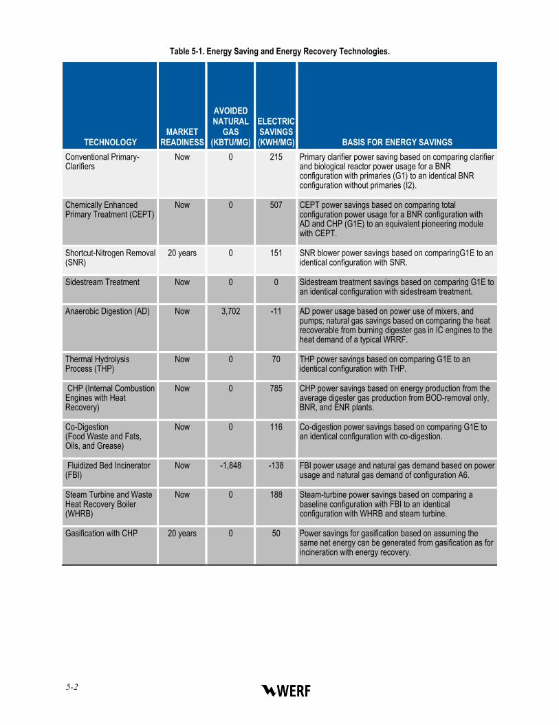
The electric savings and avoided fuel values presented in Table 5-1 were calculated by comparing the technology application to different WRRF configurations modeled for the WERF ENER1C12 project.
5-2
Table 5-1. Energy Saving and Energy Recovery Technologies.
TECHNOLOGY
MARKET READINESS
AVOIDED NATURAL
GAS (KBTU/MG)
ELECTRIC SAVINGS (KWH/MG)
BASIS FOR ENERGY SAVINGS
Conventional Primary-Clarifiers
Now 0 215 Primary clarifier power saving based on comparing clarifier and biological reactor power usage for a BNR configuration with primaries (G1) to an identical BNR configuration without primaries (I2).
Chemically Enhanced Primary Treatment (CEPT)
Now 0 507 CEPT power savings based on comparing total configuration power usage for a BNR configuration with AD and CHP (G1E) to an equivalent pioneering module with CEPT.
Shortcut-Nitrogen Removal (SNR)
20 years 0 151 SNR blower power savings based on comparingG1E to an identical configuration with SNR.
Sidestream Treatment Now 0 0 Sidestream treatment savings based on comparing G1E to an identical configuration with sidestream treatment.
Anaerobic Digestion (AD) Now 3,702 -11 AD power usage based on power use of mixers, and pumps; natural gas savings based on comparing the heat recoverable from burning digester gas in IC engines to the heat demand of a typical WRRF.
Thermal Hydrolysis Process (THP)
Now 0 70 THP power savings based on comparing G1E to an identical configuration with THP.
CHP (Internal Combustion Engines with Heat Recovery)
Now 0 785 CHP power savings based on energy production from the average digester gas production from BOD-removal only, BNR, and ENR plants.
Co-Digestion (Food Waste and Fats, Oils, and Grease)
Now 0 116 Co-digestion power savings based on comparing G1E to an identical configuration with co-digestion.
Fluidized Bed Incinerator (FBI)
Now -1,848 -138 FBI power usage and natural gas demand based on power usage and natural gas demand of configuration A6.
Steam Turbine and Waste Heat Recovery Boiler (WHRB)
Now 0 188 Steam-turbine power savings based on comparing a baseline configuration with FBI to an identical configuration with WHRB and steam turbine.
Gasification with CHP 20 years 0 50 Power savings for gasification based on assuming the same net energy can be generated from gasification as for incineration with energy recovery.

Utilities of the Future Energy Findings 5-3
Technology pathways to energy neutrality were selected for each of the most commonly used main liquid stream and solids process configurations among large facilities, as shown in Tables 5-2 and 5-3.
Energy flow (“Sankey”) diagrams for the main liquid stream and solids process matching configurations are provided in Appendix B. In addition to these modifications, gasification, and incineration were applied to the appropriate facility sizes, as shown in Table 5-4. Plant schematics for the eight technology pathways to energy neutral WRRFs are provided in Appendix C.
Table 5-2. Main Liquid Stream Treatment Modifications to Achieve Energy Neutrality.
MAIN LIQUID STREAM TREATMENT
(MATCHING BASELINE CONFIGURATION)
PRIMARY CLARIFIERS CEPT SNR
MODIFICATIONS TO ACHIEVE ENERGY NEUTRALITY
BOD Removal Only with Primary Treatment (B) No YES No Convert Primary Clarifiers to CEPT
Nitrification without Primary Treatment (E) YES YES YES Add CEPT and SNR
Nitrification with Primary Treatment (E) No YES YES
Convert Primary Clarifiers to CEPT and add SNR
BNR with Primary Treatment (G) No YES YES Convert Primary Clarifiers to CEPT and BNR to SNR
ENR with Primary Treatment and Chemical P. Removal (M) No YES YES
Convert Primary Clarifiers to CEPT and ENR to SNR
Mainstream A/B (P) No No YES Convert B Stage to SNR

5-4
Table 5-3. Solids Process Modifications to Achieve Energy Neutrality.
SOLIDS PROCESS
(MATCHING CONFIGURATION)
SIDESTREAM TREATMENT AD
CHP, THP, CO-DIGESTION FBI
WHRB AND STEAM
TURBINE
MODIFICATIONS TO ACHIEVE ENERGY
NEUTRALITY
Aerobic Digestion (2)
YES YES YES No No Convert to AD, Add Sidestream Treatment, Add THP, Co-digestion and CHP
AD (1) YES No YES No No Add Sidestream Treatment, THP, Co-digestion and CHP
AD with FBI (1+6) YES No YES No YES Add Sidestream Treatment, THP, Co-digestion and CHP, Add WHRB and Steam Turbine
AD with MHI (1+5) YES No YES YES YES Add Sidestream Treatment, THP, Co-digestion and CHP, Convert to FBI, Add WHRB and Steam Turbine
FBI (6) No No No No YES Add WHRB and Steam Turbine
MHI (5) No No No YES YES Convert to FBI, Add WHRB and Steam Turbine
AD = Anaerobic Digestion; CHP = Combined Heat and Power; THP = Thermal Hydrolysis Process; FBI = Fluidized Bed Incineration; MHI = Multiple Hearth Incineration; WHRB = Waste Heat Recovery Boiler
Table 5-4. Incineration and Gasification Based on Plant Size.
PLANT SIZE
(MGD)
MODIFICATIONS TO ENERGY NEUTRALITY
20-50 Add gasification with syngas cleaning and CHP, use of CHP heat in low temperature dryer
>50 Add FBI and energy recovery in steam turbine
Utilities of the Future Energy Findings 5-5
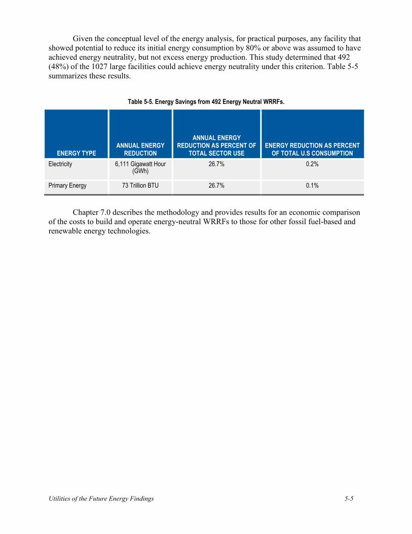
Given the conceptual level of the energy analysis, for practical purposes, any facility that showed potential to reduce its initial energy consumption by 80% or above was assumed to have achieved energy neutrality, but not excess energy production. This study determined that 492 (48%) of the 1027 large facilities could achieve energy neutrality under this criterion. Table 5-5 summarizes these results.
Table 5-5. Energy Savings from 492 Energy Neutral WRRFs.
ENERGY TYPE
ANNUAL ENERGY REDUCTION
ANNUAL ENERGY REDUCTION AS PERCENT OF
TOTAL SECTOR USE
ENERGY REDUCTION AS PERCENT OF TOTAL U.S CONSUMPTION
Electricity 6,111 Gigawatt Hour (GWh)
26.7% 0.2%
Primary Energy 73 Trillion BTU 26.7% 0.1%
Chapter 7.0 describes the methodology and provides results for an economic comparison of the costs to build and operate energy-neutral WRRFs to those for other fossil fuel-based and renewable energy technologies.

5-6

Utilities of the Future Energy Findings 6-1
CHAPTER 6.0
NITROGEN-ENERGY NEXUS
The water-energy nexus (see Energy-Water Report to Congress, December 2006) refers to the relationship between water demand for energy production and the energy demand for water supply. UOTFs, which recover resources from water, particularly the chemical constituents containing carbon and nitrogen, also recognize a connection between nitrogen treatment processes and increased energy demand. This is the nitrogen-energy nexus.
With the implementation of the provisions of the Clean Water Act, passed in 1972, the discharge of treated wastewater has met secondary standards for Biochemical Oxygen Demand (BOD) and Total Suspended Solids (TSS). Both of these parameters were measurements generally related to the carbon-based constituents in domestic wastewater. Over time, with the greater number of water-quality based permits limiting nutrients in discharged water and with the U.S. EPA’s National Nutrient Strategy, more facilities which manage wastewater are required to remove or recover nitrogen as well as carbon-based constituents.
Nitrogen is present in wastewater in inorganic and/or organic form. Inorganic nitrogen forms include ammonia, nitrate, and nitrite. Microorganisms in water, and cultivated in biological activated sludge processes, convert nitrogen between forms. Ammonia, the unoxidized form of nitrogen, is toxic to aquatic life. Some facilities use a microbial process called nitrification to change the ammonia to the less toxic form of nitrate. Nitrate, however, accelerates eutrophication, or the growth of algae in water, due to the nutrient value of the nitrate. WRRFs that discharge treated water into nutrient-affected waters are often required to reduce total nitrogen from their discharge to very low levels. This is typically done through a combination of nitrification/denitrification treatment process stages.
Using well-established processes (e.g., Biological Nutrient Removal (BNR) or enhanced nutrient removal (ENR)) for nitrogen conversion from water-borne forms of nitrogen (e.g., ammonia, nitrate) to inert nitrogen gas, WRRFs can expect to see an increase in energy demand. For more discussion on nutrient discharge limits and the best performance of established treatment technologies, see WERF report NUTR1R06i, Nutrient Management: Regulatory Approaches to Protect Water Quality Volume I – Review of Existing Practices.

6-2
Figure 6-1. Typical Electric Power Demand for Various Levels of Wastewater Treatment Necessary
to Meet Nutrient Limited and Advanced Discharge Permits (from WERF ENER1C12).
In addition to an increased energy demand, BNR and ENR processes require additional carbon in order to provide a source of food for the denitrifying bacteria. This carbon, commonly in the form of methanol, acetic acid or other organics, is added to the denitrification stage. The primary energy content of the additional carbon source is so significant that WRRFs with these nitrogen removal processes have little hope of achieving net energy neutrality. For example, at a typical BNR facility, the electricity and natural gas required to produce an external carbon source is approximately 2.5 times the chemical energy needed for nutrient removal.
Table 6-1. Modeled Net Energy Recovery Potential Available in Different Process Configurations for Nitrogen Control.
Modeled Facility Net Electric Energy Recovery Potential
BOD Removal with Enhanced Primary, AD, CHP 139%
Nitrification with Enhanced Primary, AD, CHP 110%
BNR with Enhanced Primary, AD, CHP 61%
ENR with Enhanced Primary, AD, CHP 49%
Avant-garde research into emerging processes using recently identified anaerobic ammonium oxidizing (anammox) organisms can, without organic carbon, convert ammonia to nitrogen gas. The development of processes with these microorganisms has led to the treatment concept termed Shortcut Nitrogen Removal (SNR). SNR, particularly for use in mainstream applications, is an innovative process tested at full-scale in only one location in the U.S. at the time of this report. Other groundbreaking research is underway at additional facilities in the U.S. and Europe. (For more information see WERF project INFR6R11). The ability to produce low-
Utilities of the Future Energy Findings 6-3
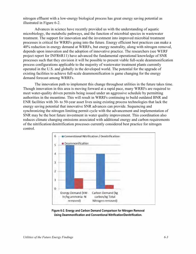
nitrogen effluent with a low-energy biological process has great energy saving potential as illustrated in Figure 6-2.
Advances in science have recently provided us with the understanding of aquatic microbiology, the metabolic pathways, and the function of microbial species in wastewater treatment. The support for innovation and the investment into improved microbial treatment processes is critical for WRRFs going into the future. Energy efficient best practices can make a 40% reduction in energy demand at WRRFs, but energy neutrality, along with nitrogen removal, depends upon innovation and the adoption of innovative practice. The researchers (see WERF project report for INFR6R11) have advanced the fundamental operational knowledge of SNR processes such that they envision it will be possible to present viable full-scale deammonification process configurations applicable to the majority of wastewater treatment plants currently operated in the U.S. and globally in the developed world. The potential for the upgrade of existing facilities to achieve full-scale deammonification is game changing for the energy demand forecast among WRRFs.
The innovation path to implement this change throughout utilities in the future takes time. Though innovation in this area is moving forward at a rapid pace, many WRRFs are required to meet water-quality driven permits being issued under an aggressive schedule by permitting authorities in the meantime. This will result in WRRFs continuing to build outdated BNR and ENR facilities with 30- to 50-year asset lives using existing process technologies that lack the energy saving potential that innovative SNR advances can provide. Sequencing and synchronizing the nitrogen limiting permit cycle with the advancement and implementation of SNR may be the best future investment in water quality improvement. This coordination also reduces climate changing emissions associated with additional energy and carbon requirements of the nitrification/denitrification processes currently considered best practice for nitrogen control.
Figure 6-2. Energy and Carbon Demand Comparison for Nitrogen Removal
Using Deammonification and Conventional Nitrification/Denitrification.

6-4
Utilities of the Future Energy Findings 7-1
CHAPTER 7.0
LEVELIZED COST OF ENERGY FOR ENERGY NEUTRAL WRRFS
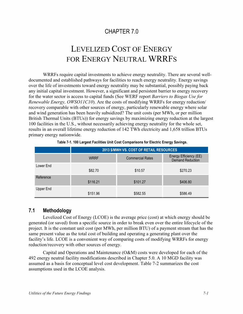
WRRFs require capital investments to achieve energy neutrality. There are several well-documented and established pathways for facilities to reach energy neutrality. Energy savings over the life of investments toward energy neutrality may be substantial, possibly paying back any initial capital investment. However, a significant and persistent barrier to energy recovery for the water sector is access to capital funds (See WERF report Barriers to Biogas Use for Renewable Energy, OWSO11C10). Are the costs of modifying WRRFs for energy reduction/ recovery comparable with other sources of energy, particularly renewable energy where solar and wind generation has been heavily subsidized? The unit costs (per MWh, or per million British Thermal Units (BTUs)) for energy savings by maximizing energy reduction at the largest 100 facilities in the U.S., without necessarily achieving energy neutrality for the whole set, results in an overall lifetime energy reduction of 142 TWh electricity and 1,658 trillion BTUs primary energy nationwide.
Table 7-1. 100 Largest Facilities Unit Cost Comparisons for Electric Energy Savings.
2013 $/MWH VS. COST OF RETAIL RESOURCES
WRRF Commercial Rates
Energy Efficiency (EE) Demand Reduction
Lower End
$82.70 $10.57 $270.23
Reference
$116.21 $101.27 $406.80
Upper End
$151.96 $582.55 $586.49
7.1 Methodology Levelized Cost of Energy (LCOE) is the average price (cost) at which energy should be
generated (or saved) from a specific source in order to break even over the entire lifecycle of the project. It is the constant unit cost (per MWh, per million BTU) of a payment stream that has the same present value as the total cost of building and operating a generating plant over the facility’s life. LCOE is a convenient way of comparing costs of modifying WRRFs for energy reduction/recovery with other sources of energy.
Capital and Operations and Maintenance (O&M) costs were developed for each of the 492 energy neutral facility modifications described in Chapter 5.0. A 10 MGD facility was assumed as a basis for conceptual level cost development. Table 7-2 summarizes the cost assumptions used in the LCOE analysis.

7-2
Table 7-2. LCOE Cost Assumptions.
COST CATEGORY
INPUTS
Capital Costs Based on 10 MGD capacity, scaled using weighted scaling factors1
Labor Costs Bottom up buildup for a 10 MGD facility, scaled using scaling factors
Maintenance Costs 2% of capital costs
Overhead Costs 1% of capital costs
Variable O&M Costs Bottom up $/MGD buildups of chemical, solid disposal and other variable costs
Avoided Energy WERF ENER1C12 team energy modeling
1 To approximate plant costs, this analysis developed capital costs weighted scaling factors. The scaling factors for different technologies are presented in Appendix C.
Detailed descriptions of assumptions and inputs are provided in Appendix D.
The study compares LCOE to other sources of electricity. However, the modifications to WRRFs go beyond conventional and renewable sources of energy in that they also lead to reductions in natural gas use due to the opportunities for thermal energy recovery (e.g., anaerobic digester heating, building heat, heat source for drying biosolids). The analysis accounts for this additional source in the following two ways:
Comparing LCOE in terms of $/MWh. In this case, natural gas savings from the WRRF modifications are treated as an O&M cost reduction in the LCOE analysis.
Comparing LCOE in terms of $/million BTU. In this case, both electrical and natural gas energy savings are converted to equivalent primary energy in million BTU and $/million BTU cost is calculated for all sources of energy.

Utilities of the Future Energy Findings 7-3
7.2 General Assumptions and Scenario Analysis Table 7-3 shows the assumptions the research team applied. The team developed
sensitivity results from three distinct scenarios in order to bracket the range of the LCOE given different input variable assumptions.
Table 7-3. LCOE Analysis Scenario Assumptions – Energy Neutral WRRFs.
INPUT VARIABLE
UNIT
SCENARIO ASSUMPTIONS
Upper End Reference Case Lower End
Project Life Years 20 30 30
Inflation % 3.0% 2.5% 2.0%
Discount Rate % 8.0% 6.0% 6.0%
Labor Cost $/hr. 40 35 30
Capacity Factor % 65% 75% 85%
Natural Gas Costs $/MJ Low Resource Scenario1
EIA Reference Scenario2
High Resource Scenario3
Capital Costs No Change No Change 10% Lower
1EIA Annual Energy Outlook 2013, Low Oil and Gas Resource Scenario. 2 EIA Annual Energy Outlook 2013, Reference Case. 3 EIA Annual Energy Outlook 2013, High Oil and Gas Resource Scenario.
In the reference case, the analysis uses LCOE over a 30-year project lifecycle. Industry averages demonstrate that WRRF assets tend to have operational lives that in most cases extend 30-40 years. (Design of Municipal Wastewater Treatment Plants – WEF MOP No. 8, pages 2-65).
7.3 LCOE Results Researchers found achievable potential for electric and primary energy reductions to be
183,333 GWh and 3,650 trillion BTU respectively, over the LCOE analysis period, based on the annual savings presented in Table 5-5. For the reference scenario, the present value of the cost to achieve these levels of energy reduction is $17.9 billion. Capital investment is $13.2 billion (nominal) over the 2014-2033 investment period, or $588 million per year. These results are equivalent to an LCOE of $304.15 per MWh or $26.14 per million BTU of primary energy.
Figures 7-1 and 7-2 present cumulative electric and primary energy savings respectively, both over the full 50-year analysis period consisting of 20 years technology roll out, design, and construction period, followed by a 30-year asset life. Figure 7-3 presents annual and cumulative capital costs.

7-4
Figure 7-1. Cumulative Electric Energy Savings for Converting 492 Large WRRFs to Energy Neutral Over 50-Year Time Frame.
Figure 7-2. Cumulative Primary Energy Savings for Converting 492 Large WRRFs to Energy Neutral Over 50-Year Time Frame.

Utilities of the Future Energy Findings 7-5
Figure 7-3. Capital Costs for Converting 492 Large WRRFs to Energy Neutral Over 20-Year Technology Roll Out, Design, and Construction Time Frame.
Tables 7-4 and 7-5 and Figures 7-4 and 7-5 compare LCOE estimates for energy neutral WRRFs with other technologies as presented in the EIA 2013 Annual Energy Outlook. The comparison is presented in terms of electrical energy and primary energy.
As indicated in Table 7-4, the electricity generated in a WRRF is dispatchable and distributed. The term dispatchable denotes a source of electricity that can be brought online whenever the electric grid system requires it. It is important to note that WRRFs are also distributed resources, or small-scale facilities used to produce electricity close to the end users of power. Availability of distributed resources often reduces need for investment in electric transmission and distribution, as well as eliminates losses involved in transporting electrical energy from generator to customer.

7-6
Table 7-4. LCOE Comparisons for Electrical Energy Savings.
RANGE
LCOE (2013 $)/MWH
Dispatchable, Distributed Dispatchable, Utility-Scale Non-Dispatchable, Utility-Scale
WRRF NG-CT NG-CC Hydro Solar PV Wind
Lower End $209.25 $109.27 $65.66 $61.36 $118.20 $77.22
Reference $304.71 $136.58 $70.50 $94.87 $151.61 $90.98
Upper End $406.37 $157.38 $82.16 $156.75 $235.76 $104.85
Table 7-5. LCOE Comparisons for Primary Energy Savings.
RANGE
LCOE (2013 $)/MMBTU PRIMARY ENERGY
Dispatchable, Distributed Dispatchable, Utility-Scale
Non-Dispatchable, Utility-Scale
WRRF NG-CT NG-CC Hydro Solar PV Wind
Lower End $18.40 $9.59 $5.77 $5.39 $10.38 $6.78
Reference $26.14 $11.99 $6.19 $8.33 $13.31 $7.99
Upper End $34.28 $13.82 $7.21 $13.77 $20.70 $9.21

Utilities of the Future Energy Findings 7-7
Figure 7-4. LCOE Comparison Chart for Electrical Energy Savings – Energy Generation Technologies.
Figure 7-5. LCOE Comparison Chart for Primary Energy Savings – Energy Generation Technologies.

7-8
When considering these results, note that other energy generation facilities are all utility-scale (tens to hundreds of MW facilities) with significant economies of scale, whereas WRRFs represent a distributed source of energy with production and savings of less than 5 MW for all but the very largest facilities. The sole objective of investment into all utility-scale generation technologies is to generate electric power. However, many of the modifications required for achieving energy reduction at WRRFs have important additional benefits, such as reduction in nutrients discharged to waterways, reduction in the quantity of solids disposed of in landfills, pathogen reduction in biosolids, and nutrient recovery in biosolids to offset application of synthetic fertilizers. None of the other energy technologies have such a wide variety of environmental and societal benefits.
WRRF energy resources represented in the LCOE graphs above are spread over 492 WRRFs larger than 5 mgd identified as having the potential to be energy neutral. It is more cost-effective to convert a proportion of these facilities to energy neutral than others. Plant capacity is a key factor, with very large facilities (over 50 mgd) showing significant economies of scale. According to the 2008 CWNS data, 100 WRRFs treat over 50 mgd in the United States.
Due to different facility process configurations as a baseline starting point, the cost of upgrading the large WRRF to energy neutral differ between facilities, with some upgrades being cost-competitive based on the LCOE. The conversion of the 100 cost-competitive WRRFs to energy neutrality are also evaluated and identified separately. Figures 7-6 and 7-7 present frequency distributions of average LCOE to modify WRRFs to energy neutrality. The analysis assumes a 10-year lagged implementation of projects, meaning once the technology is market ready, it would be first implemented at the facilities where the lowest LCOE can be achieved and then implemented incrementally at other facilities in order of lowest to highest LCOE.

Utilities of the Future Energy Findings 7-9
Figure 7-6. Frequency Distribution for Electrical Energy Savings.
Figure 7-7. Frequency Distribution for Primary Energy Savings.

7-10
7.4 Energy Investment in WRRFs Table 7-6 compares the energy reduction opportunity and investment costs for three
nationwide program options to convert large WRRFs to energy neutral or to maximize energy efficiency and recovery although not reaching energy neutral. The highest cost option involves converting all 492 large WRRFs with the potential to become energy neutral to achieve energy neutrality. The program with the second highest cost involves converting to energy neutral only the top 100 facilities that can be converted at competitive LCOE. The final option evaluated, maximizing energy reduction at the largest 100 facilities, without necessarily achieving energy neutrality at every very large facility, is the least cost option. The last program option also results in higher overall lifetime energy reduction.
Table 7-6. Lifetime Energy Reduction and Associated Cost.
PROGRAM OPTION
DESCRIPTION
LIFETIME ENERGY REDUCTION AVERAGE LCOE
ESTIMATED CAPITAL
COST (Nominal $
Billions)
Electrical (TWh)
Primary (Trillion BTU)
Electrical ($/MWh)
Primary ($/million
BTU)
1. 492 Energy Neutral Facilities
Convert 492 large facilities to energy neutral.
183 2,195 $304.15 $26.14 $13.2
2. 100 Energy Neutral Facilities – competitive LCOE
Convert 100 large facilities to energy neutral at competitive LCOE
119 1,410 $164.98 $14.53 $4.8
3. 100 Largest Facilities
Maximize energy reduction at 100 largest facilities (above 50 MGD)
142 1,658 $116.21 $10.34 $3.8
As previously stated, it is important when considering these results to note that energy reduction/recovery at WRRFs represents a distributed source of energy and has the advantage of being a dispatchable and reliable source of energy demand reduction. Electric utilities place value on systems that have the flexibility to reduce demand during peak times. Electric rate structures reflect such value; rate structures vary considerably depending on location due to needed capacity, existing energy resource mix, and the demand charge portion of the electric bill. Payment incentives offered to customers for energy efficiency (EE) and demand reduction through demand side management (DSM) programs are opportunities to further reduce the electric bill for WRRFs.
Table 7-7 and Figure 7-8 compare the LCOE of energy neutral WRRFs to retail electric rates and the cost incurred by utilities for EE and DSM programs. Results show that WRRFs can be a very competitive energy resource compared to some of these programs.

Utilities of the Future Energy Findings 7-11
Table 7-7. 100 Energy Neutral Facilities LCOE Comparisons for Electric Energy Savings.
RANGE
LCOE (2013 $)/MWH VS. COST OF RETAIL RESOURCES
WRRF Commercial Rates EE-Demand Reduction
Lower End $115.57 $10.57 $270.23
Reference $164.98 $101.27 $406.80
Upper End $223.36 $582.55 $586.49
Source: Commercial rates data: Electric Sales, Revenue, and Average Price (2012 Data) Table T7 EE-Demand Reduction Data: Electric Power Annual (2012 Data) Table 10.3 & Table 10.5
Table 7-8. 100 Largest Facilities LCOE Comparisons for Electric Energy Savings.
LCOE (2013 $)/MWH VS. COST OF RETAIL RESOURCES
WRRF Commercial Rates EE-Demand Reduction
Lower End $82.70 $10.57 $270.23
Reference $116.21 $101.27 $406.80
Upper End $151.96 $582.55 $586.49

7-12
Figure 7-8. LCOE Comparison Chart for 100 Energy Neutral WRRF Electrical Energy Savings versus Commercial Rates and Demand Response Programs.
Figure 7-9. LCOE Comparison Chart for Largest 100 WRRF Electrical Energy Savings versus Commercial Rates and Demand Response Programs.
Electrical Savings Commercial Rates EE-DR
Electrical Savings Commercial Rates EE-DR

Utilities of the Future Energy Findings 8-1
CHAPTER 8.0
THERMAL ENERGY RECOVERY
Most (>80%) of the energy contained in wastewater is in the form of thermal energy. Distributed wastewater source heat pumps can extract this energy from raw wastewater in the collection and conveyance system and from the effluent of WRRFs to supply district heating within a respective service area.
The lack of existing infrastructure to distribute the hot water and the need for the heating demand to be in close proximity to the heat pump installations to minimize heat loss remain the two major barriers to recovering thermal energy from wastewater to provide district heating needs. Despite these barriers, district heating networks are prevalent in European cities, providing up to 100% of the heating demand of many cities. Smaller networks exist in the U.S., providing heat to some large commercial buildings and university campuses throughout the country.
Key characteristics that better suit certain cities to utilize wastewater source heat pumps for district heating include relatively cold winter climates and large, high density population centers. The research team selected 17 cities based on the criteria listed in Table 8-1 – accounting for approximately 6% of the U.S. population – as the basis for estimating recoverable thermal energy in the wastewater sector.
Table 8-1. Characteristics of Cities Selected for Estimating Thermal Energy Recovery Using Wastewater Source Heat Pumps.
CRITERIA UNIT THRESHOLD
Population capita >300,000
Urban Density people per square mile >5,000
Average Winter Temperature °F <40
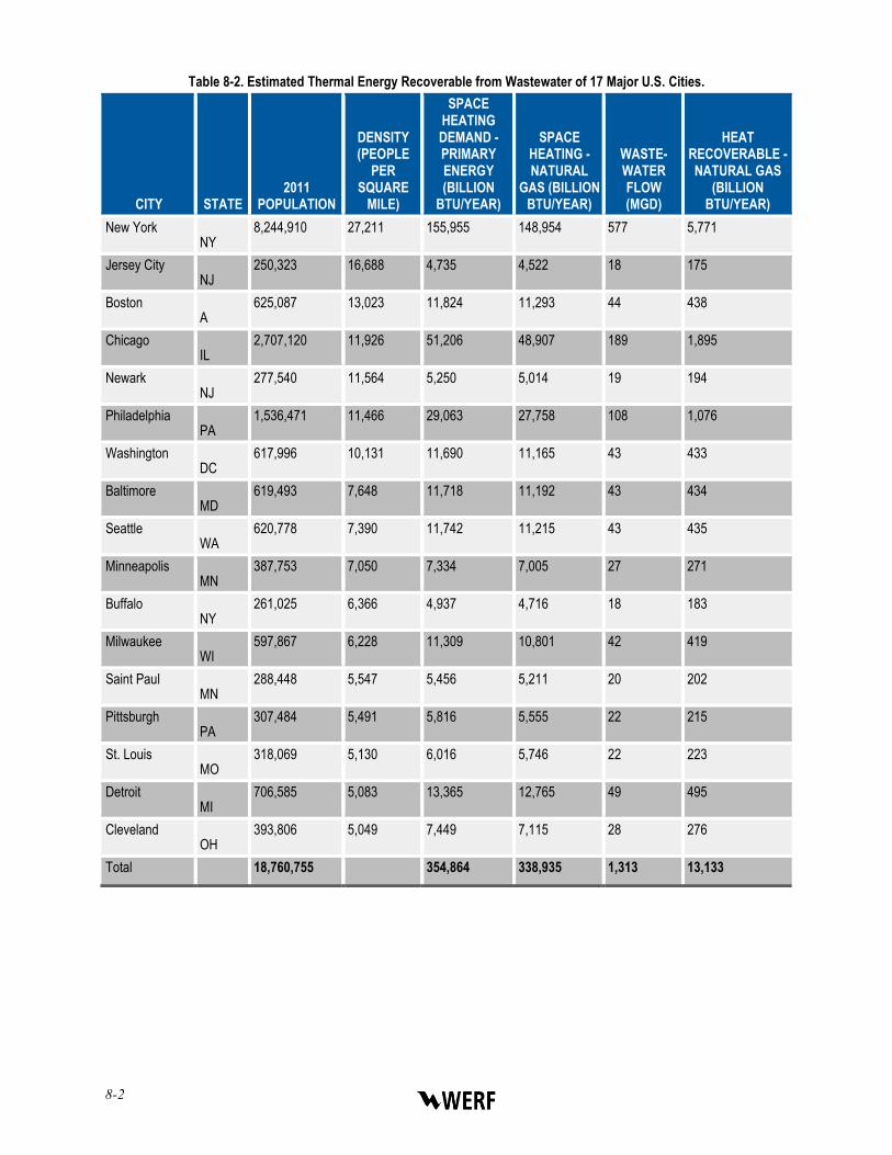
The cities’ heating demand and thermal energy recovery potential are shown in Table 8-2. The research team estimated the residential heating demand at 355 trillion BTU of primary energy per year, based on a national average residential heating demand of 19 million BTU per capita per year (Sanders and Webber, 2012).
The thermal energy recovery potential is based on a commercially available wastewater source heat pump with a heat output of 83.3 BTU/gallon and an average per capita wastewater production of 70 gallons per day. As shown in Table 8-2, the thermal energy recovery for the selected cities is around 13 trillion BTU per year (assuming natural gas-fired boilers operating at 80% efficiency), or 4% of their total combined residential heating demand. This amount of recovered energy offsets 5% of primary energy use for the U.S. wastewater sector. This accounts, however, for only 2% of the 691 trillion BTU/year of thermal energy that is available sector-wide.
8-2
Table 8-2. Estimated Thermal Energy Recoverable from Wastewater of 17 Major U.S. Cities.
CITY
S
STATE
2011 POPULATION
DENSITY (PEOPLE
PER SQUARE
MILE)
SPACE HEATING DEMAND - PRIMARY ENERGY (BILLION
BTU/YEAR)
SPACE HEATING - NATURAL
GAS (BILLION BTU/YEAR)
WASTE-WATER FLOW (MGD)
HEAT RECOVERABLE - NATURAL GAS
(BILLION BTU/YEAR)
New York NNY
8,244,910 27,211 155,955 148,954 577 5,771
Jersey City NNJ
250,323 16,688 4,735 4,522 18 175
Boston MA
625,087 13,023 11,824 11,293 44 438
Chicago IIL
2,707,120 11,926 51,206 48,907 189 1,895
Newark NNJ
277,540 11,564 5,250 5,014 19 194
Philadelphia PPA
1,536,471 11,466 29,063 27,758 108 1,076
Washington DDC
617,996 10,131 11,690 11,165 43 433
Baltimore MMD
619,493 7,648 11,718 11,192 43 434
Seattle WWA
620,778 7,390 11,742 11,215 43 435
Minneapolis MMN
387,753 7,050 7,334 7,005 27 271
Buffalo NNY
261,025 6,366 4,937 4,716 18 183
Milwaukee WWI
597,867 6,228 11,309 10,801 42 419
Saint Paul MMN
288,448 5,547 5,456 5,211 20 202
Pittsburgh PPA
307,484 5,491 5,816 5,555 22 215
St. Louis MMO
318,069 5,130 6,016 5,746 22 223
Detroit MMI
706,585 5,083 13,365 12,765 49 495
Cleveland OOH
393,806 5,049 7,449 7,115 28 276
Total 18,760,755 354,864 338,935 1,313 13,133

Utilities of the Future Energy Findings 8-3
8.1 Levelized Cost of Energy (LCOE) The LCOE analysis for thermal energy recovery from wastewater is based on general
assumptions listed in Table 8-3. The unit capital cost of $332,020 per million BTU-hr for a wastewater source heat pump and district heating network is based on installed costs from the Vancouver Olympic Village. The capital costs include cost of the heat pump and screens, a building to house the equipment, and a district heating network of buried insulated pipes. The research team treated the capital cost of a boiler as an avoided cost, since a heat pump would replace the use of a more conventional natural gas fired boiler. Note that the costs do not include cost of heat exchangers to connect individual users to the master heating loop, service loops of individual customers, meters, etc.
Table 8-3. LCOE Assumptions.
INPUT
UNIT
ASSUMPTIONS
Investment Period Years 20
Net Capital Cost $2013/MMBTU-hr. of heat delivered 332,020
Inflation % 2.5%
Discount Rate % 6.0%
Maintenance Cost $2013/MMBTU-hr. of heat delivered 0.22
Labor Cost $2013/hr. 35
Days of Operation per Year Days 120
Heat Pump Coefficient of Performance (COP)
2.40
Primary Energy Factor (Electric) 3.34
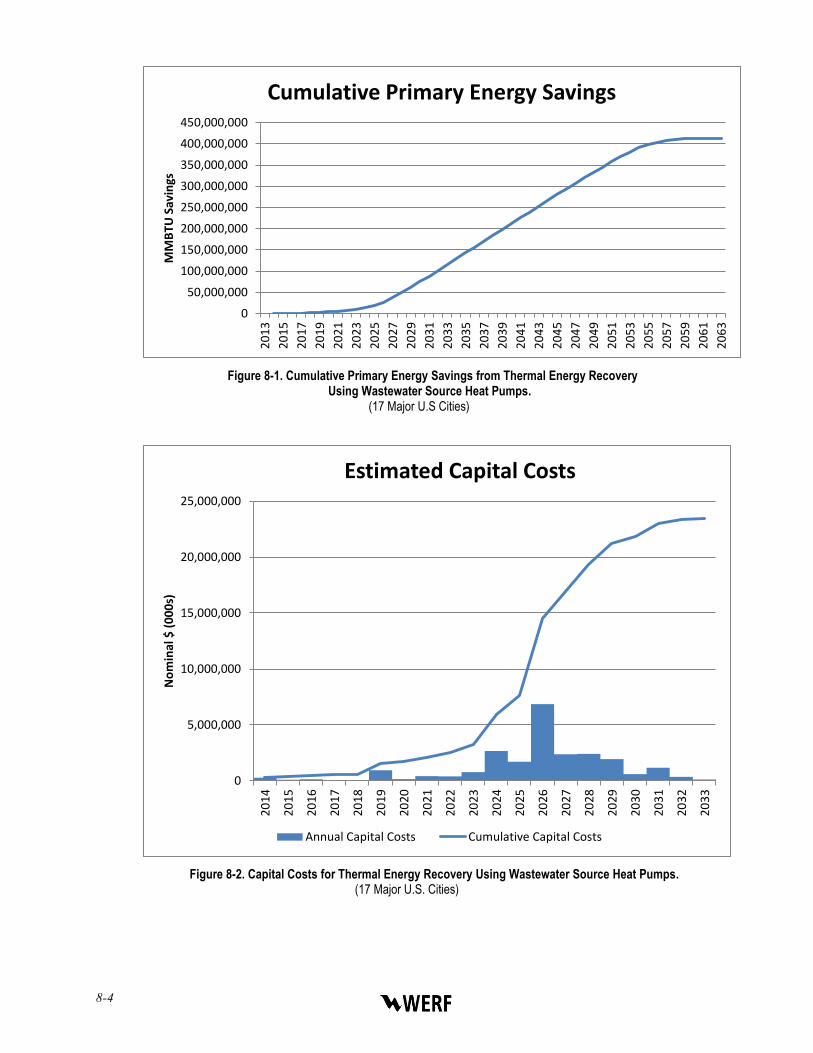
The investment in heat recovery infrastructure was assumed to follow the same general 20-year investment pattern as that of WRRFs. Figure 8-1 presents energy savings over the 50-year implementation period. Figure 8-2 presents the annual and cumulative capital investments.
8-4
Figure 8-1. Cumulative Primary Energy Savings from Thermal Energy Recovery Using Wastewater Source Heat Pumps.
(17 Major U.S Cities)
Figure 8-2. Capital Costs for Thermal Energy Recovery Using Wastewater Source Heat Pumps. (17 Major U.S. Cities)
0
50,000,000
100,000,000
150,000,000
200,000,000
250,000,000
300,000,000
350,000,000
400,000,000
450,000,000
20
13
20
15
20
17
20
19
20
21
20
23
20
25
20
27
20
29
20
31
20
33
20
35
20
37
20
39
20
41
20
43
20
45
20
47
20
49
20
51
20
53
20
55
20
57
20
59
20
61
20
63
MM
BTU
Sav
ings
Cumulative Primary Energy Savings
0
5,000,000
10,000,000
15,000,000
20,000,000
25,000,000
20
14
20
15
20
16
20
17
20
18
20
19
20
20
20
21
20
22
20
23
20
24
20
25
20
26
20
27
20
28
20
29
20
30
20
31
20
32
20
33
No
min
al $
(0
00
s)
Estimated Capital Costs
Annual Capital Costs Cumulative Capital Costs

Utilities of the Future Energy Findings 8-5
The results demonstrate an opportunity for an additional 412 trillion BTU in energy savings through thermal heat recovery from wastewater. The value of the cost to achieve this level of energy reduction is $51.5 billion. Capital investment is $23.5 billion (nominal) over the 2014-2033 investment period, or $1.2 billion per year. These results are equivalent to a LCOE of $52.11 per million BTUof primary energy.
The thermal energy recovered is a direct substitute for the use of natural gas or heating oil used for space heating across the U.S. Again, like electric power, the LCOE is comparable to available retail alternatives. Table 8-4 and Figure 8-3 compare the combined LCOE to retail commercial rates of natural gas and the cost of natural gas EE projects across the U.S.
Table 8-4. Comparison of LCOE to Retail Gas Rates and Energy Efficiency Projects.
CASE WEIGHTED AVERAGE
LCOE (2013 $) RETAIL NATURAL GAS RATES - COMMERCIAL1 EE - NATURAL GAS
Lower End $23.20 $5.08 $5.34
Reference $30.25 $8.84 $7.65
Upper End $38.65 $15.57 $52.87
1Based on team’s survey of commercial rates from 101 U.S natural gas utilities.
Figure 8-3. Comparison of LCOE to Retail Gas Resources.
WRRF Recovery LCOE (2013 $) Retail Gas Rates – Commercial Retail Gas Rates - Industrial

8-6

Utilities of the Future Energy Findings 9-1
CHAPTER 9.0
CONCLUSIONS
The electric demand for wastewater treatment services in the United States has been estimated since the mid-1990s (EPRI, 1996). However there has been little known about the nationwide potential to recover energy from domestic wastewater, or the potential for energy efficiency and recovery savings by this sector. As utilities look to the future and transform themselves into water resource recovery facilities (WRRFs), the scope of possible energy recovery and savings needs to be better understood by policy makers. This study uses robust models of process configurations with related energy-balance projections extrapolated nationwide to generate the findings.
This study estimated the total available energy in the United States wastewater sector (851 trillion BTUs/year). This is five times the energy demand estimated for treatment of domestic wastewater in the U.S. This estimate of primary energy is the sum of the chemical, heat, and kinetic energy sources. 80% of the energy in wastewater is in the form of heat, while 20% is chemical energy. Kinetic (hydraulic) energy is specific to the location of the facility and represents less than 1% of energy in wastewater nationwide.
The energy management program option which maximizes overall energy reduction for the largest 100 WRRFs in the U.S. is both the least cost option and the one that saves the most energy. It has a nationwide overall lifetime (30 year) reduction of 142 TWh electricity and 1,658 trillion BTUs primary energy.
WRRFs represent a distributed, dispatchable, and reliable source of energy. Many of the modifications required for achieving energy reduction at WRRFs also have additional important benefits, such as a reduction in nutrients discharged to waterways, a reduction in the quantity of solids disposed of in landfills, pathogen reduction in biosolids, and nutrient recovery in biosolids to offset the application of synthetic fertilizers. None of the other renewable energy technologies such as solar or wind have such a wide variety of environmental and societal benefits.
A large majority (>80%) of the energy contained in wastewater is in the form of thermal energy. Through the use of distributed wastewater source heat pumps, WRRFs can extract this energy from raw wastewater in the collection and conveyance system and from effluents at facilities, reusing it to supply district heating within their respective service areas.
Barriers to recovering thermal energy from wastewater include the lack of existing infrastructure to distribute the recovered heat as well as the need for the heating demand to be in close proximity to the heat pump installations in order to minimize heat loss during distribution. Despite these barriers, district heating networks are prevalent in European cities and provide up to 100% of the heating demand in some areas. Smaller networks exist in the U.S., providing heat to large commercial buildings and university campuses. The recovered thermal energy is a direct substitute for the current widespread use of natural gas or heating oil used for space heating across the U.S.
More utilities of the future will be required to remove nitrogen as well as carbon and pathogens from their treated discharges to protect water quality in certain waterbodies. Using

9-2
only accepted processes (e.g., Biological Nutrient Reduction (BNR)) for nitrogen conversion from waterborne forms (ammonia, nitrate) to inert nitrogen gas, WRRFs can expect to see an increase in energy demand. However, emerging processes can use anammox microorganisms in a low-energy biological treatment process called shortcut nitrogen removal (SNR). SNR, particularly for use in mainstream applications, is an innovative nitrogen conversion process.
The ability to produce low-nitrogen effluent by using a low-energy process has great potential. However, the support for innovation and the investment into improved microbial processes is critical to advance significant improvements in the water resource recovery sector. Energy efficient best practices can reduce 40% of energy demand at WRRFs, but energy neutrality with nitrogen removal depends upon innovation and the adoption of these practices.
9.1 Recommendations
Although the available studies, including this one, which refine the estimates of energy demand and energy generation potential are valuable, there are almost no studies that collect and use actual energy data from WRRFs. Data collection on biogas generation and the WRRFs with capabilities to generate biogas through anaerobic digestion (see http://www.wrrfdata.org/biogas/) is underway in a collaboration through the National Biosolids Partnership (NBP), a program operated by the Water Environment Federation (WEF) along with the National Association of Clean Water Agencies (NACWA). This is a major effort and more information on this practice for renewable energy recovery and its potential is still needed.
Real electric use data by WRRFs collected from at least an adequate subset of WRRFs is necessary both to establish the current baseline and also to measure electric demand changes as energy efficient upgrades are implemented or nutrient removal processes are required. The New York State Energy Research and Development Authority is collaborating with WERF to collect electric utility use data for larger WRRFs in New York state. (See WERF ENER7C13). However, data from a wider distribution of plants and process configurations would inform and substantiate the nationwide estimates and the agencies that rely on these projections.
Utilities of the Future Energy Findings A-1
APPENDIX A
ENERGY BALANCE DIAGRAMS OF BASELINE CONFIGURATIONS FROM
WERF ENER1C12

A-2
B
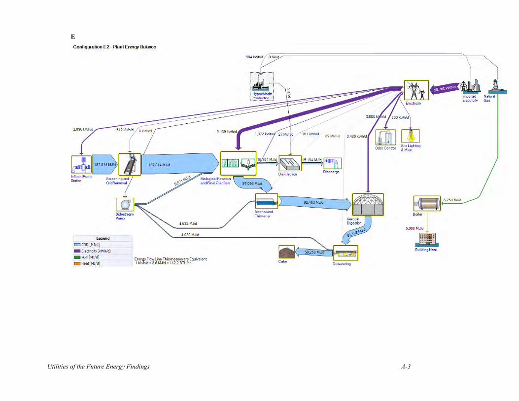
Utilities of the Future Energy Findings A-3
E
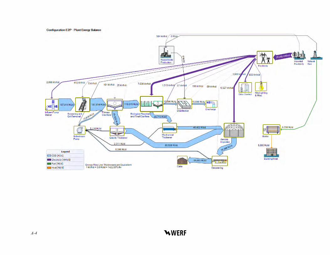
A-4

Utilities of the Future Energy Findings A-5
G

A-6
M

Utilities of the Future Energy Findings A-7
P

A-8
AD
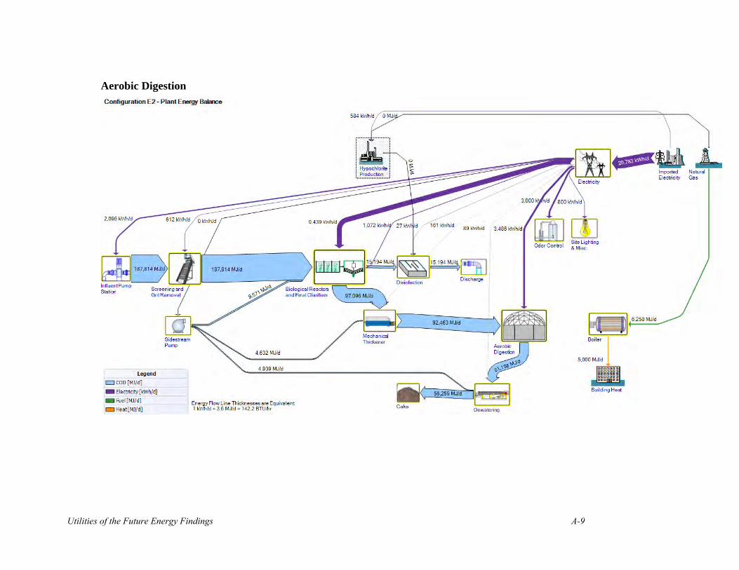
Utilities of the Future Energy Findings A-9
Aerobic Digestion

A-10
MHI

Utilities of the Future Energy Findings A-11
FBI

A-12

Utilities of the Future Energy Findings B-1
APPENDIX B
ENERGY SAVING AND ENERGY RECOVERYTECHNOLOGIES EVALUATED
PRIMARY TREATMENT
Enhanced Primary Treatment
CEPT
Ballasted flocculation/settling
Fine screens
Membranes (UF followed by RO or NF)
SECONDARY TREATMENT
Short SRT Step Feed
Anaerobic lagoon with gas capture
Nitrite Shunt (SNR)
Mainstream Annamox (Simultaneous Nitritation‐Denitritation) (SNR)
Mainstream Anaerobic Treatment
Upflow Anaerobic Sludge Blanket (UASB)
Anaerobic Migrating Blanket Reactor
Submerged Anaerobic Membrane Reactor (SAMBR)
Targeted aeration and Advanced Oxidation
Superbugs or Immobilized Enzyme Treatment
Microbial Fuel Cells
Phototrophic treatment using algae
Membranes (UF followed by RO or NF)
SIDESTREAM TREATMENT
Sidestream P Recovery (OSTARA)
Sidestream N Removal (Deammonification)

B-2
SOLIDS MANAGEMENT PROCESSES
Improved dewatering efficiency
AD Pretreatment
Advanced Digestion (Acid‐Gas)
Digestion Pretreatment (Thermal Hydrolysis)
Digestion Pretreatment (OpenCEL)
Co-digestion
FOG Co‐Digestion
Food Processing Waste Co-Digestion
Residential Sink Food Processing
Higher efficiency CHP
Fuel Cells
Thermal Processes
Low temperature Heat Drying
FBI with Energy Recovery in Steam Turbine
Gasification with IC Engine
Pyrolysis
Supercritical Water Oxidation (SCWO)
Supercritical Gasification with IC Engine
Steam reforming (gasification with H2 separation and use in fuel cell)
Energy Recovery from Incineration or CHP via Organic Rankine Cycle (ORC)
THERMAL ENERGY RECOVERY
Heat pumps
Adsorption chillers
HYDRAULIC ENERGY RECOVERY
Micro-hydro

Utilities of the Future Energy Findings C-1
APPENDIX C
TECHNOLOGY PATHWAYS TO ENERGY NEUTRALITY
C-1. Secondary Treatment Only with AD (only applied to plants >20 mgd).
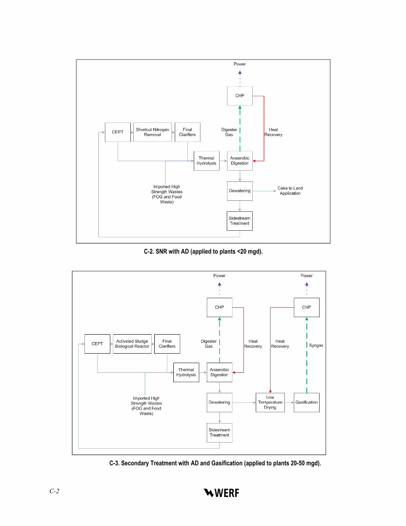
C-2
C-2. SNR with AD (applied to plants <20 mgd).
C-3. Secondary Treatment with AD and Gasification (applied to plants 20-50 mgd).

Utilities of the Future Energy Findings C-3
C-4. SNR with AD and Gasification (applied to plants 20-50 mgd).
C-5. Secondary Treatment with AD and Incineration (applied to plants >50 mgd).

C-4
C-6. SNR with AD and Incineration (applied to plants >50 mgd).
C-7. Secondary Treatment with Incineration (applied to plants already with incineration).

Utilities of the Future Energy Findings C-5
C-8. SNR with Incineration (applied to plants already with incineration).

C-6

Utilities of the Future Energy Findings D-1
APPENDIX D
LCOE ASSUMPTIONS
MODIFICATION
CAPITAL COSTS (BASED ON
10 MGD PLANT) MAINTENANCE
LABOR OPERATIONS
LABOR
OTHER VARIABLE
COSTS
Units 2013 $ Hours Hours $/MGD
Primary-Clarifiers $ 2,000,000 970 2,912 $ -
CEPT Cost Inputs $ 917,991 970 2,912 $12,140
Shortcut-N $ 700,000 970 2,912 $ 35,000
Sidestream-Treatment $1,851,351 970 2,912 $ (1,360)
AD $ 9,348,119 1,463 1,092 $ -
THP $ 5,130,000 1,484 8,736 $(28,400)
CHP $1,541,000 1,472 2,184 $ -
Co-Digestion $ 768,167 373 3,912 $3,572
FBI $3,480,000 145 438 $ (34,700)
Steam-Turbine $1,000,000 145 438 $ -
Gasification $ 9,970,000 1,484 8,736 $ (34,700)
Capital Cost Curves
Capital Cost (X MGD) = ($/MGD) Capital Cost Based on 10 MGD * X MGD *Capex Factor

D-2
Where Capex Factor is given in the table below.
MGD CAPACITY AD THP CHP FBI STEAM-
TURBINES GASIFICATION
5 1.06 2.00 1.06 - – –
10 1.00 1.00 1.00 - – –
20 0.74 0.50 0.74 - – 0.50
50 0.42 0.36 0.42 0.20 0.24 0.20
100 0.26 0.18 0.26 0.12 0.14 0.12
200 0.15 0.15 0.15 0.07 0.08 0.07
500 0.07 0.10 0.07 0.03 0.14 0.03
1000 0.04 0.06 0.04 0.02 0.20 0.02
Weight 18% 44% 12% 3% 1% 21%
Labor Scaling Factors
NOMINAL FLOW CAPACITY (MGD) MAINT. LABOR FACTORS PS. LABOR FACTORS
5 100% 100%
10 100% 100%
20 125% 100%
50 150% 150%
100 200% 150%
200 300% 200%
500 400% 200%
1000 400% 200%

Utilities of the Future Energy Findings R-1
REFERENCES
Electric Power Research Institute (1996). Water and Wastewater Industries: Characteristics and Energy Management Opportunities. Electric Power Research Institute, Inc.
Electric Power Research Institute (2002). Technical Report. 1006787. Water and Sustainability (Volume 4): U.S. Electricity Consumption for Water Supply and Treatment.
Electric Power Research Institute (2013). Technical Report. 3002001433. Electricity Use and Management in the Municipal Water Supply and Wastewater Industries. Electric Power Research Institute, Inc.
Heidrich, ES., T.P. Curtis, and J. Dolfing (2011). “Determination of the Internal Chemical Energy of Wastewater”, Vol. 45, No. 2, Environmental Science and Technology, pg. 827.
National Association of Clean Water Agencies (NACWA) (2009). Renewable Energy Recovery Opportunities from Domestic Wastewater.
National Association of Clean Water Agencies (NACWA) (2011). NACWA Financial Survey: A National Survey of Clean Water Agency Financing and Trends.
SAIC (2006). Water and Wastewater Energy Best Practice Guidebook, Wisconsin Focus on Energy.
Sanders, Kelly T. and M.E. Webber. 2012. Evaluating the energy consumed for water use in the United States. Environmental Research Letters 7.
Sandia National Laboratories. (2006) Energy Demands on Water Resources – Report to Congress on the Interdependency of Energy and Water. U.S. Department of Energy.
Shizas, I. and D.M. Bagley (2004). “Experimental Determination of Energy Content of Unknown Organics in Wastewater Streams”, Journal of Energy Engineering. August.
Tchobanoglous, G. and H. Leverenz (2009). “Impacts of New Concepts and Technology on the Energy Sustainability of Wastewater Management” presented at Conference on Climate Change, Sustainable Development and Renewable Resources in Greece. October 17, 2009.
U.S. Energy Information Administration (2013). Annual Energy Outlook 2013.
U.S. EPA (2002). Onsite Wastewater Treatment Systems Manual. Table 3.2.
U.S. EPA (2008). Clean Water Needs Survey 2008. http://water.epa.gov/scitech/datait/databases/cwns/2008reportdata.cfm
U.S. EPA (2014). Energystar. http://www.energystar.gov/buildings/facility-owners-and-managers/existing-buildings/use-portfolio-manager.
Water Environment Foundation (2010). Design of Municipal Wastewater Treatment Plants Manual of Practice No. 8, Fifth Edition.

R-2
Water Environment Research Foundation (2010) Nutrient Management: Regulatory Approaches to Protect Water Quality Volume I – Review of Existing Practices WERF Report No. NUTR1R06i.
Water Environment Research Foundation (2011). Exploratory Team Report – Energy Management. Published as Ener1 Fact Sheet.
Water Environment Research Foundation (2012). Barriers to Biogas Use for Renewable Energy, WERF Report No. OWSO11C10.
Water Environment Research Foundation (2013). The Water Resources Utility of the Future…A Blueprint for Action, WERF Report No. WERF3C12. Published by WERF, WEF, and NACWA.
Water Environment Research Foundation (2014). Mainstream Deammonification. WERF Report No. INFR6R11.
Water Environment Research Foundation (2015). Net-Zero Energy Solutions for Water Resource Recovery Facilities, WERF Report No. ENER1C12.
Wett, B., K. Buchauer, and C. Fimml. (2007). Energy Self-Sufficiency as a Feasible Concept for Wastewater Treatment Systems. Proc. IWA Leading Edge Technology Conference, Singapore, Asian Water, Sept. 2007, 21-24

WERF Subscribers
WASTEWATER UTILITY
Alabama Montgomery Water Works
& Sanitary Sewer Board
Alaska Anchorage Water &
Wastewater Utility Arizona Avondale, City of Glendale, City of Peoria, City of Phoenix Water Services
Department Pima County Wastewater
Reclamation Department Tempe, City of
Arkansas Little Rock Wastewater
California Central Contra Costa
Sanitary District Corona, City of Crestline Sanitation District Delta Diablo Dublin San Ramon Services
District East Bay Dischargers
Authority East Bay Municipal Utility
District Encino, City of Fairfield-Suisun Sewer
District Fresno Department of
Public Utilities Inland Empire Utilities
Agency Irvine Ranch Water District Las Gallinas Valley
Sanitary District Las Virgenes Municipal
Water District Livermore, City of Los Angeles, City of Montecito Sanitation
District Napa Sanitation District Novato Sanitary District Orange County Sanitation
District Palo Alto, City of Riverside, City of Sacramento Regional
County Sanitation District
San Diego, City of San Francisco Public
Utilities, City and County of
San Jose, City of Sanitation Districts of Los
Angeles County Santa Barbara, City of Santa Cruz, City of Santa Rosa, City of Silicon Valley Clean Water South Coast Water District
South Orange County Wastewater Authority
Stege Sanitary District Sunnyvale, City of Thousand Oaks, City of Union Sanitary District West Valley Sanitation
District
Colorado Aurora, City of Boulder, City of Greeley, City of Littleton/Englewood
Wastewater Treatment Plant
Metro Wastewater Reclamation District
Platte Canyon Water & Sanitation District
Connecticut Greater New Haven
WPCA
District of Columbia DC Water
Florida Fort Lauderdale, City of JEA Hollywood, City of Miami-Dade County Orange County Utilities
Department Palm Beach County Pinellas County Utilities Reedy Creek Improvement
District St. Petersburg, City of Tallahassee, City of Toho Water Authority
Georgia Atlanta Department of
Watershed Management
Augusta, City of Clayton County Water
Authority Cobb County Water
System Columbus Water Works Gwinnett County
Department of Water Resources
Macon Water Authority Savannah, City of
Hawaii Honolulu, City & County of
Idaho Boise, City of
Illinois Greater Peoria Sanitary
District Metropolitan Water
Reclamation District of Greater Chicago
Sanitary District of Decatur
Indiana Jeffersonville, City of
Iowa Ames, City of Cedar Rapids Water
Pollution Control Facilities
Des Moines, City of Kansas Johnson County
Wastewater Louisville and Jefferson
County Metropolitan Sewer District
Olathe, City of Overland Park, City of
Kentucky Sanitation District No. 1
Louisiana Sewerage & Water Board
of New Orleans
Maine Bangor, City of Portland Water District
Maryland Anne Arundel County Howard County Bureau of
Utilities Washington Suburban
Sanitary Commission
Massachusetts Boston Water & Sewer
Commission Upper Blackstone Water
Pollution Abatement District
Michigan Ann Arbor, City of Detroit, City of Gogebic-Iron Wastewater
Authority Holland Board of Public
Works Saginaw, City of Wayne County Department
of Public Services Wyoming, City of
Minnesota Metropolitan Council
Environmental Services Rochester, City of Western Lake Superior
Sanitary District
Missouri Independence, City of Kansas City Missouri
Water Services Department
Metropolitan St. Louis Sewer District
Nebraska Lincoln Wastewater &
Solid Waste System Nevada Henderson, City of New Jersey Bergen County Utilities
Authority Ocean County Utilities
Authority
New York New York City Department
of Environmental Protection
North Carolina Charlotte-Mecklenburg
Utilities Durham, City of Metropolitan Sewerage
District of Buncombe County
Old North State Water Company Inc.
Orange Water & Sewer Authority
Raleigh, City of
Ohio Akron, City of Avon Lake Municipal
Utilities Columbus, City of Metropolitan Sewer District
of Greater Cincinnati Montgomery County Water
Services Northeast Ohio Regional
Sewer District Summit County
Oklahoma Oklahoma City Water &
Wastewater Utility Department
Tulsa, City of
Oregon Albany, City of Bend, City of Clean Water Services Gresham, City of Lake Oswego, City of Oak Lodge Sanitary District Portland, City of Water Environment
Services
Pennsylvania Philadelphia, City of,
Water Department University Area Joint
Authority
South Carolina Beaufort - Jasper Water &
Sewer Authority Charleston Water System Greenwood Metropolitan
District Mount Pleasant
Waterworks Spartanburg Water Sullivan’s Island, Town of
Tennessee Cleveland Utilities Murfreesboro Water &
Sewer Department Nashville Metro Water
Services Texas Austin, City of Dallas Water Utilities Denton, City of

WERF Subscribers El Paso Water Utilities Fort Worth, City of Houston, City of San Antonio Water System Trinity River Authority
Utah Salt Lake City Department
of Public Utilities
Virginia Alexandria Renew
Enterprises Arlington County Fairfax County Fauquier County Hampton Roads Sanitation
District Hanover County Henrico County Hopewell Regional
Wastewater Treatment Facility
Loudoun Water Lynchburg Regional
Wastewater Treatment Plant
Prince William County Service Authority
Richmond, City of Rivanna Water & Sewer
Authority
Washington Everett, City of King County Department
of Natural Resources & Parks
Puyallup, City of Seattle Public Utilities Sunnyside, Port of Yakima, City of
Wisconsin Green Bay Metro
Sewerage District Kenosha Water Utility Madison Metropolitan
Sewerage District Milwaukee Metropolitan
Sewerage District Racine Water &
Wastewater Utility Sheboygan, City of Stevens Point, City of Wausau Water Works
Australia/New Zealand
Water Services Association of Australia
Canada Calgary, City of EPCOR Lethbridge, City of Regina, City of Toronto, City of Winnipeg, City of
STORMWATER UTILITY
California Monterey, City of San Diego County
Department of Public Works
San Francisco Public Utilities, City & County of
Santa Rosa, City of Sunnyvale, City of
Colorado Aurora, City of Boulder, City of
Florida Orlando, City of
Iowa Cedar Rapids Water
Pollution Control Facilities Des Moines, City of
Kansas
Overland Park, City of
Pennsylvania
Philadelphia, City of, Water Department
Tennessee
Chattanooga Stormwater Management
Washington
Bellevue Utilities Department
Seattle Public Utilities
STATE AGENCY
Connecticut Department of Environmental Protection
Fresno Metropolitan Flood Control District
Harris County Flood Control District
Kansas Department of Health & Environment
Ohio River Valley Sanitation Commission
Urban Drainage & Flood Control District, CO
CORPORATE
AECOM Alan Plummer Associates
Inc. American Cleaning Institute Aqua-Aerobic Systems Inc. Atkins Black & Veatch
Corporation Brown and Caldwell Burns & McDonnell Carollo Engineers, P.C. CDM Smith CH2M HILL CRA Infrastructure &
Engineering
D&B/Guarino Engineers LLC
Effluential Synergies LC EMA Inc. ENVIRON International
Corporation Environmental Operating
Solutions Inc. Evoqua Water
Technologies Gannett Fleming Inc. GeoSyntec Consultants GHD Inc. Global Water Advisors Inc. Greeley & Hansen LLC Hazen & Sawyer P.C. HDR Inc. HNTB Corporation Holmes & McGrath Inc. Infilco Degremont Inc. Jacobs Engineering
Group Inc. KCI Technologies Inc. Kelly & Weaver P.C. Kennedy/Jenks Consultants Larry Walker Associates LimnoTech Malcolm Pirnie, the Water
Division of ARCADIS MaxWest Environmental
Systems McKim & Creed Michael Baker, Jr. Inc. MWH NTL Alaska Inc. Parametrix Inc. Praxair Inc. Pure Technologies Ltd. Ross Strategic Stone Environmental Inc. Stratus Consulting Inc. Synagro Technologies Inc. Tata & Howard Inc. Tetra Tech Inc. The Cadmus Group Inc. The Low Impact
Development Center Inc. URS Corporation Versar, Inc. Westin Engineering Inc. Wright Water
Engineers Inc. Zoeller Pump Company
Australia CSIRO
Austria Sanipor Ltd.
Canada Associated Engineering O2 Environmental Inc. Trojan Technologies Inc.
Norway Aquateam Cowi AS
INDUSTRY
American Water Anglian Water Services
Ltd. Chevron Energy
Technology Company Dow Chemical Company DuPont Company Eastman Chemical
Company Eli Lilly & Company FMC Corporation InSinkErator Johnson & Johnson Merck & Company Inc. Procter & Gamble
Company Suez Environnement United Utilities North West United Water Services LLC VandCenter Syd Veolia Water North
America List as of 9/10/14

Chair
Terry L. Johnson, Ph.D.,
P.E., BCEE
Black & Veatch
Corporation
Vice-Chair
Rajendra P. Bhattarai, P.E.,
BCEE
Austin Water Utility
Thomas C. Granato, Ph.D.
Metropolitan Water
Reclamation District of
Greater Chicago
Donald Gray (Gabb),
Ph.D., P.E., BCEE
East Bay Municipal
Utility District
Robert Humphries, Ph.D.
Water Corporation of
Western Australia
David Jenkins, Ph.D.
University of California
at Berkeley
Mark W. LeChevallier,
Ph.D.
American Water
Ted McKim, P.E. BCEE
Reedy Creek
Energy Services
Elizabeth Southerland,
Ph.D.
U.S. Environmental
Protection Agency
Paul Togna, Ph.D.
Environmental Operating
Solutions, Inc.
Art K. Umble, Ph.D., P.E.,
BCEE
MWH Global
Kenneth J. Williamson,
Ph.D., P.E.
Clean Water Services
Chair
Catherine R. Gerali
Metro Wastewater
Reclamation District
Vice-Chair
Kevin L. Shafer
Metro Milwaukee
Sewerage District
Secretary
Eileen J. O’Neill, Ph.D.
Water Environment
Federation
Treasurer
Brian L. Wheeler
Toho Water Authority
Paul L. Bishop, Ph.D., P.E.,
BCEE
University of
Rhode Island
Glen Daigger, Ph.D., P.E.,
BCEE, NAE
CH2M Hill
Scott D. Dyer, Ph.D.
The Procter & Gamble
Company
Philippe Gislette
Degrémont,
Suez-Environnement
Julia J. Hunt, P.E.
Trinity River Authority
of Texas
Terry L. Johnson, Ph.D.,
P.E., BCEE
Black & Veatch
Corporation
Jim Matheson
Oasys Water
Ed McCormick, P.E.
Union Sanitary District
James Anthony (Tony)
Parrott
Metropolitan Sewer
District of Greater
Cincinnati
Cordell Samuels
Regional Municipality
of Durham, ON
Interim Executive Director
Lawrence P. Jaworski,
P.E., BCEE
WERF Research Council
WERF Board of Directors


Method of Payment: (All orders must be prepaid.)
q C heck or Money Order Enclosedq V i s a q M a s t e r c a r d q A m e rican Express
______________________________________________________
______________________________________________________
To Order (Subscribers Only):
To Order (Non-Subscribers):
S h i p p i n g & H a n d l i n g :
Amount of Order United States Canada & Mexico All Others
* m i n i mum amount for all orders
Stock # P r o d u c t Quantity Unit Price To t a l
Postage &Handling
VA Residents Add 5% Sales Tax
Canadian ResidentsAdd 7% GST
Up to but not more than:
More than $200.00
Add:
Add 20% of order
Add:
Add 20% of order
$7.50* 8.00 8.50 9.0010.0011.00
13.00 15.00 18.00
$9.509.509.50
18.0018.0018.0024.0035.0040.00
Add:50% of amount40% of amount
$20.0030.0040.0050.0060.0080.00
100.00150.00200.00
W E R F P r o d u c t O r d e r F o r m
Account No. Exp. Date
Signature
TOTAL
Log on to www. werf.org and clickon “Publications.”
Phone: 571-384-2100 Fa x : 703-299-0742
WERFAttn: Subscriber Services635 Slaters LaneAlexandria, VA 22314-1177
Make checks paya ble to the Water Environment Research Foundation.
(
7
Non-subscribers may order WERFpublications either through WERFor IWAP (www.iwapublishing.com).Visit WERF’ s website at www.werf.orgfor details.
As a benefit of joining the Water Environment Research Foundation, subscribers are entitled to receive one complimentary c o py of all finalr e p o rts and other products. Additional copies are ava i l a ble at cost (usually $10). To order your complimentary c o py of a report, please wri t e“ f r e e ” in the unit price column. WERF keeps tra ck of all orders. If the charge differs from what is shown here, we will call to confirm the totalb e fore processing.
________________________________________________________________________________________________
________________________________________________________________________________________________
________________________________________________________________________________________________
________________________________________________________________________________________________
________________________________________________________________________________________________
Name Title
Organization
Address
City State Zip Code Country
Phone Fax Email


UtilitiesoftheFutureEnergyFindings
Water Environment Research Foundation635 Slaters Lane, Suite G-110 n Alexandria, VA 22314-1177
Phone: 571-384-2100 n Fax: 703-299-0742 n Email: [email protected]
WERF Stock No. ENER6C13
September 2014
Co-published by
IWA PublishingAlliance House, 12 Caxton StreetLondon SW1H 0QSUnited KingdomPhone: +44 (0)20 7654 5500Fax: +44 (0)20 7654 5555Email: [email protected]: www.iwapublishing.comIWAP ISBN: 978-1-78040-680-0/1-78040-680-0
Co-published by
Utilities of the FutureEnergy Findings
Energy
ENER6C13_WEF-IWAPspread.qxd 4/23/2014 8:27 AM Page 1