tutorial on iec 61850 - homepage sc d2 -...
TRANSCRIPT

Tutorial on IEC 61850Lima, October 14th, 2015
14/10/2015
1
Thierry Lefebvre, EDF
Carlos Rodriguez, REE
Jaume Darne, PullNet
Thierry Coste, EDF

Contents
1. At the beginning,
1. a strong need for standards dedicated to susbtations, relationshipswith CIGRE
2. What is 61850 ?
1. Description of the main characteristics, The 61850 series for substations
2. The data model
3. Focus on communication inside and between substations (+ network topology & Ethernet configuration)
4. Communications services, tools and roles
3. Extensions…towards a universal protocol for transmission & distribution automation
1. Areas addressed: wind farms, hydro, DER, telecontrol, energystorage…
2. Roadmap for short term extensions
3. How to cope with 61850 extension of scope ?
4. Discussion14/10/2015
2

At the begining…a challenge…
the digital substations 80’s: several countries carried out experiments for EHV digital substations (USA,
Canada, Japan, France, Spain…) => many challenges were to be tackled:
Performances,
interfaces
Data representation & interoperability
Variousness…
Early 90’s: first attempts for a standardization at CIGRE, EPRI/IEEE…
CIGRE 35 => PiComs
AHG in TC57 on substation architecture, decision in 1995 to launch 3 WGs :
WG10: archirecture, WG11: control level, WG12: interfaces with process
End of 90’s: agreement between IEC & IEEE => stds will be developedin one place
.
61850 series for substation published in 2003
3
TC88’s demand to TC57 for Wind farm
control,Data & protocols
14/10/2015

TC57 : Power system information management &
associated information exchange
To prepare international standards for power systems control
equipment and systems including EMS, SCADA, DA, teleprotection,
and associated information exchange for real-time and non-real-time
information, used in the planning, operation and maintenance of
power systems.
Power systems management comprises control within control centres,
substations and individual pieces of primary equipment including
telecontrol and interfaces to equipment, systems and databases, which
may be outside the scope of TC 57.
___
4

TC 57 , production overview
Reference Architecture for Power System Information Exchange
Telecontrol
60870-5, derivative DNP-3 in the US
TASE.2 for inter control centres communications (60870-6)
DLMS, Information exchange for metering
61850 as universal protocol for power system management
Distribution automation: substations control, measurement & protection, teleprotection
Wind power farms control, Photovoltaic, storage
Hydro power plant
Distributed ressources control, Microgrids
Electrical Vehicle (connection to the grid)
CIM, for Common Information Model
Energy management systems (61970)
Distribution management sytems (61968)
Communication exchange for markets (62325)
Interfaces and communication profiles to Home/Building/IndustryAutomation
5
Se
cu
rity
(623
51
)

Generation
Transmission
Distribution
DER
Customer
Process
Field
Station
Operation
Enterprise
Market
Domains
Zones
Now… 61850 series is one of sets of core standards providing
interoperability in the power industry
Page 6
(Home, Building, Industry, EV, Mobility)
(Hierarchy)
IEC 61850
Substation automation
Distribution automation
Distributed Energy Resources
Hydro Power
CIM (IEC 61968, IEC 61970, IEC 62325)
Energy Management Systems
Distribution Management
Market Communication
14/10/2015

What is 61850 ? Description of the main characteristics, the 61850 series for
substations
Focus on communication inside and between substations (+
network topology & Ethernet configuration)
Data configutaion
Roles played in the 61850 environment
14/10/2015
7

What is 61850 ?
Description of the main characteristics,
Principles & contents
the IEC 61850 series for substations
14/10/2015
8

Incentives for 61850 in Substations Interoperability between pieces
of equipment (standardization of data exchanged)
Overall configuration including communication network and embedded function
Enhanced Maintenance
with a clear separation between functional representation, physical implementation and communications stacks
To cope with the drastic increase in data & in applications 14/10/2015
9

How to cope with such a complexproblem ? Interfaces interactions
14/10/2015
10

Interfaces
IF1: protection-data exchange between bay and station level
IF2: protection-data exchange between substations. This interface refers both to analog data e.g. for line differential protection and binary data e.g. for line distance protection
IF3: data exchange within bay level
IF4: Current transformer (CT) and Voltage Transformer (VT) instantaneous data transport (especially samples) from the process to the bay level. This comprises in the reverse direction also the protection trip
IF5: control-data exchange between process and bay level
IF6: control-data exchange between bay and station level
IF7: data exchange between substation (level) and a remote engineer’s workplace
IF8: direct data exchange between the bays especially for fast functions like interlocking
IF9: data exchange within station level
IF10: control-data exchange between the substation and remote control centre(s)
IF11: control-data exchange between substations. This interfaces refers to binary data e.g. for interlocking functions or inter-substation automatics
14/10/2015
11
Interfaces interactions

14/10/2015
12
A quick overview on the documentation

Real world versus Virtual world
14/10/2015
13

Structure & Content
ConfigurationPart 6: Configuration Lan-
guage for electrical
Substation IED’s
TestingPart 10: Conform. Testing
Mapping to real Comm. Networks (SCSM)Part 8-1: Mapping to MMS and ISO/IEC 8802-3
Part 9-1: Sampled Values over Serial Unidirectional
Multidrop Point-to-Point link
Part 9-2: Sampled Values over ISO/IEC 8802-3
Data ModelsBasic Communication Structure for
Substations and Feeder Equipment
Part 7-4: Compatible Logical Node Classes and
Data Classes
Part 7-3: Common Data Classes
Abstract Comm. ServicesBasic Communication Structure for
Substations and Feeder Equipment
Part 7-2: Abstract Communication Services (ACSI)
Part 7-1: Principles and Models
System AspectsPart 1: Introduction and
Overview
Part 2: Glossary
Part 3: General Requirements
Part 4: System and Project Mng
Part 5: Comm Requirements for
Functions and Device
Models
14/10/2015
14

Structure & content…relationships witha well-know model
14/10/2015
15

14/10/2015
16
Structure & Content: the logical node in itsenvironment
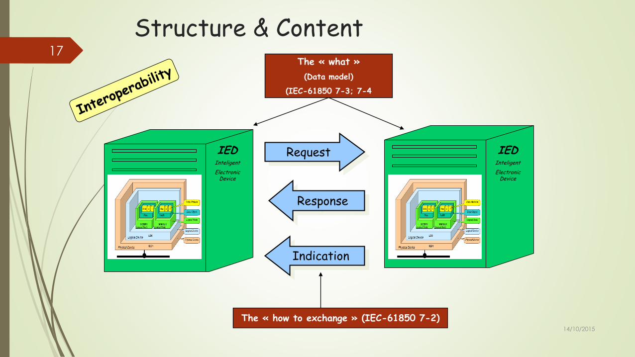
Request
Response
Indication
The « how to exchange » (IEC-61850 7-2)
The « what »
(Data model)
(IEC-61850 7-3; 7-4
IEDInteligent
ElectronicDevice
IEDInteligent
Electronic Device
14/10/2015
17
Structure & Content

7654321
Stack of communication MMS, TCP/IP , Ethernet
Mapping other protocolsCEI 61850 8.1, 9.1, 9.2
SCSM (Mappings)
Abstract Communication Service InterfaceCEI 61850 7.2ACSI (services)
IEC 61870-5DNP3OPCWebServicesDLMS
Data ModelCEI 61850 7.3, 7.4Information
Model
MMS
14/10/2015
18 General Principles

What is 61850 ?1. Description of the main characteristics,
Data model
14/10/2015
19

The data modelIEC 61850 – Communication networks and systems for power
utility automation.
The building block => Logical Node
The circuit breaker: A typical example of LN (XCBR)
From the LN to data
A hierarchical model
14/10/2015
20

Structure & content: the hierarchicalmodel of the substation
IHM CALH IHM CILO
GAPC CSWI CILO ATCC
GGIO XCBR XSWI YLTC
Interlocking on station level
HumanInterfacemachine
Alarmhandler
GenericAutomation
ProcessControl
CircuitBreaker Controler
Interlockingon bay level
Automatic Tap controler
GenericInput and
OutputControl
Circuit Breaker Tap changer Isolator
LN , substationlevel
LN, bay level
LN, process level
A generic node for al non pre-defined funtions
A generic node for al non pre-defined Process devices
14/10/2015
21

Data ModelA : Automatic control
C : Supervisory Control
D : DER (Distributed Energy Ressources)
F : Functional Blocks
G : Generic functions Process I/O
H : Hydro power
I : Interfacing and Achiving
K: Mechanical and non-electric primaryequipement
L: System Logical Nodes
M : Metering and measurement
P : Protection Functions
Q : Power Quality Events
R : Protections Related Functions
S : Supervision and Monitoring
T : Instruments Transformers and Sensors
W : Wind power
X : Switchgear
Y : Power transformer and related fonctions
Z : Further (power System) equipment
154 LOGICAL NODE (Ed2 7-4)
14/10/2015
22

Data model
14/10/2015
23
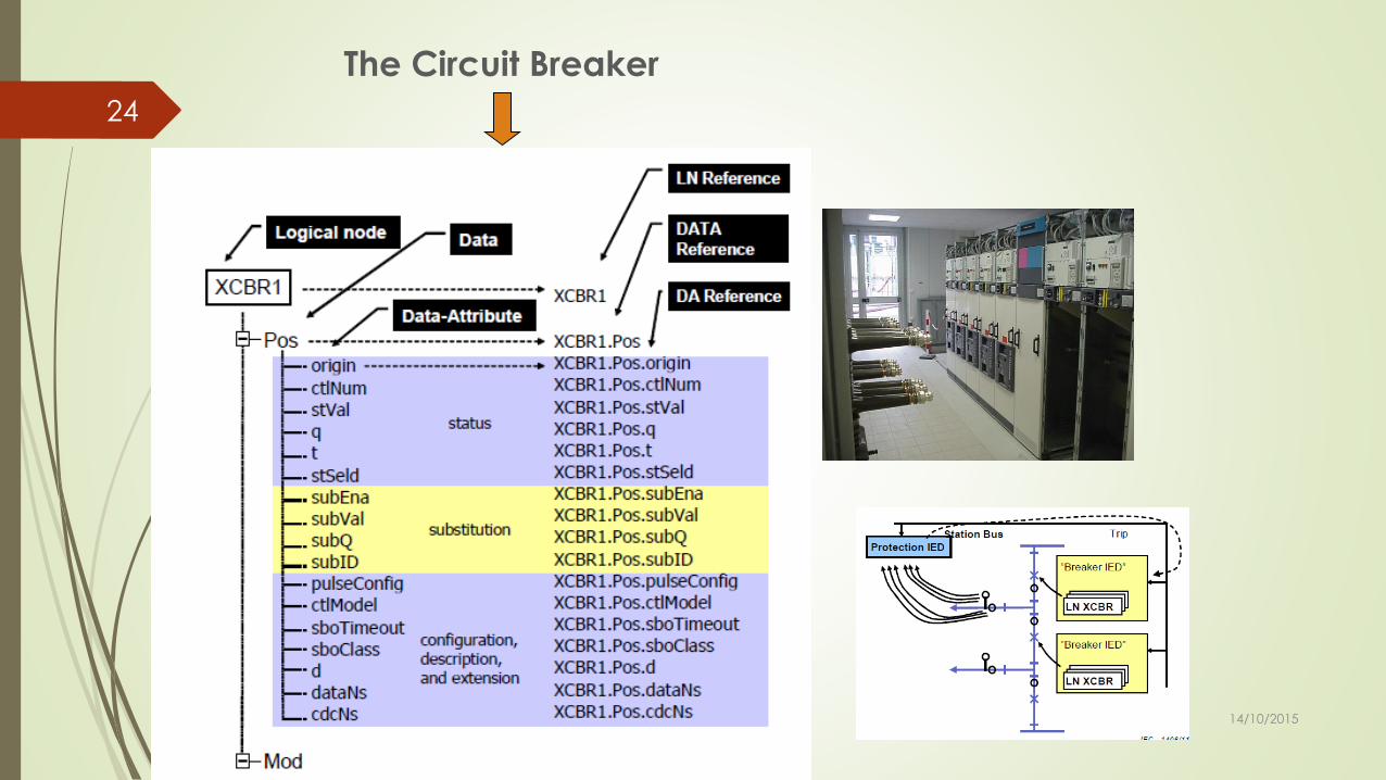
The Circuit Breaker
14/10/2015
24

DATA « Pos »
= 20 DATA ATTRIBUTES
Data Attribute « Pos.Ctval »
Control Information
ON / OFF
Data Attribute « Pos.Stval »
CB State
ON / OFF / Not valid
14/10/2015
25

IEC 61850-7-4
Mandatory / Optional / Conditional
The logical node describes the data that are needed for the inter-working
14/10/2015
26
Compatible LN and
data object classes

IEC 61850-7-3
CDC : Comon Data Class- DPC -
14/10/2015
27
Common
data classes

IEC 61850-7-3
14/10/2015
28

Data Model IEC 61850-7-3
Common Data Class (CDC) :
• States• Measurements• Triping• Parameters• Information
14/10/2015
29

LLN0 provides devicestate & mode (LD)
LPHD provides the state of the physical device or of the server (IED)
14/10/2015
30

An exampleof a simple modelisation
14/10/2015
31
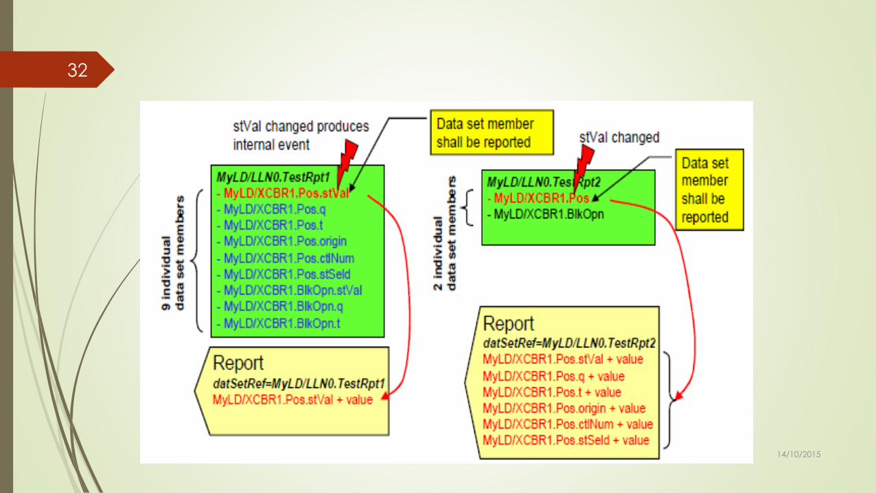
Data Set
14/10/2015
32

Part 9-2 Sampled Values
14/10/2015
33

What is 61850 ?1. Communication inside and between substations
Preliminary concepts
Network topology
Ethernet configuration
14/10/2015
34

14/10/2015
35
Remote Network Control Centre
SUBSTATION LEVEL
BAY LEVEL
PROCESS LEVEL
Comms to/from Network Level
Interbay bus (LAN)
Process bus
(Ethernet and Optical fibre)
* Operator Workstation & HMI
* Gateway to NCC
* Protection, Control and
Measurement IED’s
* I/O Remote Units
* Intelligent sensors
* Primary system devices
Sas Structure

The Bus Topology
Four main possibilities:
Single and double star• Only 1 or 2 Main Switches
• High Number of ports per switch
• High performance Switch necessary
Single and double three• IEDs are chained towards the Bay Level
• Latency in transversal Communications
• Improved resiliency compared with star
Mesh
36

The Ring Topology
Standard de facto in Industrial
Ethernet Networks
Single element failure protected
Multiple variants• Single ring
• Multiple rings chained
• Ring of the rings
Interconnecting points does not
increases significantly the risk
Deterministic topology
Balanced trade off between
efficiency and cost
37

14/10/2015
38Ring Topology
IED
SWITCH
SWITCH SWITCH SWITCH
IED IEDIEDIEDIED
WAN
BAY 1 BAY 2 BAY n

14/10/2015
39
HUBHUBHUB
HUB
IED
SWITCH
HUB
IED IEDIEDIEDIED
HUB
SWITCH
WAN
BAY 1 BAY 2 BAY n
Double Star Topology

The Cost of the Topology
40

Main Protocols Resume
RSTP + IEEE 802.1D Popular and Universal use
Compatible with all Topologies
Ring enhancements boost the recovery times up to 10 ms.
MRP IEC 62439-2 Single ring topology only. Uniform ring
R.T. depends of the switch count: 14 Sw / 10 ms, 50 Sw / 30 ms
Ethernet Filtering Database (FDB) flushed during Transition
PRP IEC 62439-3 Two independent networks with any topology
Zero packet loss but un-deterministic in some cases
Protocol implemented at the Endpoints. No recovery time
HSR IEC 62439-3 Standard HSR unpractical outside of ring topology.
Implemented on two port IEDs with bridging functionality
Zero packet loss. Un-deterministic. Duplicates the ring traffic
41

14/10/2015
42 Parallel Redundancy Protocol – “Bumpless redundancy”
Cada trama se envía simultáneamente por ambos interfaces
Al llegar las tramas al IED, una de ellas se descarta
El IED sabe en todo momento el estado de las dos redes
MERGING UNIT
ETHERNET
NETWORK
A
ETHERNET
NETWORK
B
PROTECTION
DEVICE
Ethernet frame
IEC 62439-3 PRP

14/10/2015
43HSR protocol implementation

Other Proprietary Ring Protocols
MOXA’s V-ON PROTOCOL Initially developed for multicast streaming on uniform ring
Based on previous Turbo- Ring and Turbo-Chain protocols.
Recovery time: 20 to 50 ms
KYLAND’s DT-RING Ring specific protocol. Uniform Ring
Recovery time: 40 ms for a 15 nodes network
Strongly dependent of the position and device count
KORENIX’s SUPER RING Works with single or multiple uniform rings
Recovery time 5 ms. Packet loss during transition
Proprietary patented protocol suite
44

14/10/2015
45
14/10/2015
VLAN10
VLAN20
VLAN30
VLAN40
VLAN30
VLAN40
VLAN10
VLAN20
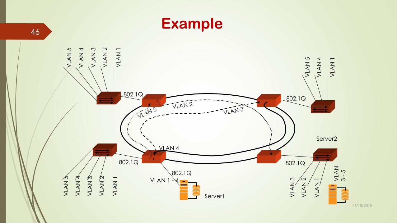
Allows the transport of some VLANs grouped in VLAN tunnel
Grouping criteria based on QoS (Q-in-Q)
VLAN stacking. Many Q-Tags stacked in the same tunnel
VLAN IDs count increased
Priorized VLAN structure
VLAN Tunneling
14/10/2015
46
Server1
Server2
802.1Q
VLA
N 1
VLA
N 2
VLA
N 3
VLA
N 4
VLA
N 5
VLA
N 1
VLA
N 2
VLA
N 3
VLA
N 4
VLA
N 5
802.1Q
VLAN 1 - 4
802.1Q
VLA
N 1
VLA
N 2
VLA
N 3 V
LAN
3 -
5
VLA
N 1
VLA
N 4
VLA
N 5
802.1Q
802.1Q
VLAN 4
Example

14/10/2015
47
Priority level 0 – Best Effort (ordinary LAN)
Priority level 1 – Background (specific applications)
Priority level 2 – not defined (reserved)
Priority level 3 – Excellent effort (business critical)
Priority level 4 – Controlled load (streaming multimedia)
Priority level 5 – Voice and Video (< than 100ms latency and jitter)
Priority level 6 – Voice and Video (< than 10ms latency and jitter)
Priority level 7 – Network control, critical, reserved traffic
Priority Criteria

14/10/2015
48IEC 61850 Recomends…

14/10/2015
49Timing Synchronization

14/10/2015
50Synchronization Requirements

Contents
1. Communication services
2. Tools
3. Roles
4. Discussion
14/10/2015
51

Communication services
IEC 61850-5: Communication requirements
IEC 61850-7-2: Abstract Communication Service Interface
(ACSI)
IEC 61850-8-1: Specific implementation of ACSI services over
Ethernet and MMS
IEC 61850-9-2 defines a specific implementation of the
Sampled Values services over Ethernet
Goal: Communication services independent of the
implementation
Specific implementations depending on the domains
14/10/2015
52

61850-5: Communication requirements
Piece of Information for COMmunication (PICOM)
Interchange of information between two logical nodes
Defined in the specification phase by the user
Part 5 defines several performance classes based on types
Type 1: Fast messages (“Protection”)
Type 2: Medium speed messages (“Automatics”)
Type 3: Low speed messages (“Operator”)
Type 4: Raw messages (“Samples”)
Type 5: File transfer functions
Type 6: Command messages and file transfer with access control
A performance class is associated to each PICOM
14/10/2015
53

61850-5: Communication requirements
Each type message is associated to typical interfaces
14/10/2015
54
Time constraint

61850-5: Communication requirements
Part of the system
specification
Each interaction between logical nodes must be
defined
Tools can be used to make
the process easier,
replicable and to generate
an SSD file
Annex A and B defined
typical PICOMS in substation automation
systems
14/10/2015
55
1 Type as defined in Annex B
PTRC

61850-5: Communication requirements
14/10/2015
56
1 Type as defined in Annex B
Time defined in part 5 is
transfer time
Process time taking into
account functions time to
process information is not
covered

61850-7-2: ACSI services
Independent of the protocol stack used for implementation
Services for
Fast interchange of information (Goose)
Data acquisition (polling, report)
Sequence of event off-line acquisition (Log)
Control model and services
Substitution model and services
Association for client-server model
Auto descriptive services (to recover IED data model)
Settings
Sampled values
Synchronization and file transfer
Create, Query, Delete Dataset
Tracking services14/10/2015
57

61850-7-2: ACSI services
Information model class
14/10/2015
58
Control model

61850-7-2: Dataset and Control Block
A dataset is an ordered set of data objects/data attribute
references of a Functional Constraint (FCD or FCDA)
A Control Block defines how a dataset is transmitted using a
specific ACSI service
14/10/2015
59
Applicable to:
Goose
Sampled values
Report
Log
Settings
Tracking

61850-8-1: ACSI services over Ethernet and MMS
Specific implementation of the ACSI services
Using Ethernet and MMS protocols
14/10/2015
60
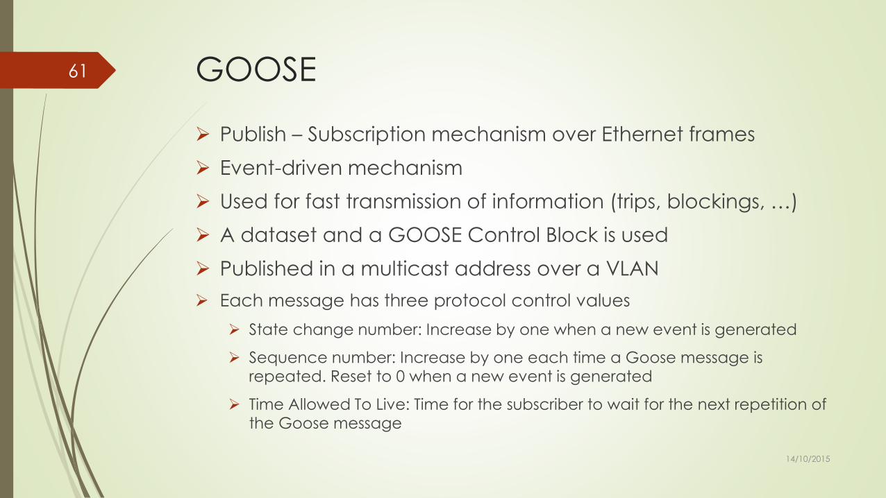
GOOSE
Publish – Subscription mechanism over Ethernet frames
Event-driven mechanism
Used for fast transmission of information (trips, blockings, …)
A dataset and a GOOSE Control Block is used
Published in a multicast address over a VLAN
Each message has three protocol control values
State change number: Increase by one when a new event is generated
Sequence number: Increase by one each time a Goose message is repeated. Reset to 0 when a new event is generated
Time Allowed To Live: Time for the subscriber to wait for the next repetition of the Goose message
14/10/2015
61

GOOSE
14/10/2015
62
IED 1 IED 2
IED 3
IED 4
switchGoose Goose
Goose
Goose
stNum=1;sqNum=128
stNum=1;sqNum=129
…
stNum=2;sqNum=0
stNum=2;sqNum=1
…
Event
T1
T1
T0
(1) sqNum is set to 0 when a
new event is detected
(2) sqNum is set to 1 when it rolls
over
stNum=2;sqNum=2

Reports
Typically used for data acquisition
Client-Server mechanism over MMS association and TCP
connection
Interested in status, quality and time tag information
Time constraint is around 200-500 ms
A dataset and a Control Block is used
Two types of service: Buffered and Unbuffered reports
Buffered report store reports when there is no connection with
the client to send them after reconnection
Trigger Options can be configured in Control Blocks
Report must be enabled by the client before receiving
information14/10/2015
63

Reports
14/10/2015
64
Client Server
ASSOCIATE-request
ASSOCIATE-confirmation
Write “OptFlds”
OK
Write “TrgOpts”
OK
Write “RptEna” = “true”
OK
Report
Report
Event
Event
< BufTm
< BufTm

61850-9-2: Sampled values
Sampled values are mapped over Ethernet
Can be unicast or multicast
Needs PPS signal
The number of samples per period is configured
Samples are numbered sequentially and reset each second
Multiple samples can be sent in the same ASDU
Control Blocks are handled using MMS (client-server services)
Typical rates: 80 samples/cycle (2 Mbps), 256 s/c (16 Mbps)
IEC 61850-9-2 LE is a specific profile widely used today
14/10/2015
65

Tools: Going deeper into the process
SCL language provides the means to configure the
communication between IEDs
Do we intend to create SCL files by hand? Of course we don’t
Standards writes about top-down approach
14/10/2015
66

Tools: Going deeper into the process
14/10/2015
67
Specification
IED Procurement
Engineering
Factory test
Installation
Commissioning
Exploitation
Logical Node Library PICOMs Single Line Diagram
Substation Automation Functions Requirements about function allocation
Specific IED allocation Specific Goose and report messages defined Specific Network architecture SCL Configuration Files generation
Configuration of IEDs Functional test
Installation of equipment Configuration of the network Wiring, functional test
Global tests, testing procedures
Diagnostics Maintenance tests Upgrades
System Specification Tool (SST)
SSD File
IED Templates Library
System Configuration Tool (SCT)
SCD file
IED Configuration Tool (ICT)
System Configuration Tool
CID, IID files
IED Configuration Tool
Testing tools
IID files
Network protocol analysers
Testing tools
System Configuration Tool

System Specification Tool
Tool to generate the final user specification using IEC 61850
semantic language and data object architecture
Creation of the logical node instances needed
Definition of the PICOMS between logical nodes
Possibility of creating virtual IEDs (collection of Logical Node
instances grouped in Logical Devices)
Virtual IEDs help the IED procurement process
The output is an SSD file to be used during the engineering
process
This tool is normally part of the System Configuration Tool
14/10/2015
68

Engineering process
Top-down approach based
Inputs: SSD file and IED Library
14/10/2015
69

System Configuration Tool (SCT)
IED independent tool to generate a System Configuration File
Creation of IED instances from IED Templates
Engineer the data flow between IEDs
Give addresses
Bind logical nodes to primary system
Handle SCL sections
Substation section (single line diagram)
Communication section, including IP address assignments
Datasets and control blocks
Allocation of report control blocks to clients
DataTypeTemplates reorganization14/10/2015
70

System Configuration Tool (SCT)
14/10/2015
71
IED instantiation
Network
ACSI services configuration
Network parameters
GOOSE
Reports, Logs
Network check
Creation of the real IEDs Allocation of IEDs per bay
Network architecture Connection of IEDs to the network
Dataset configuration Control Block configuration
IP addresses
Final GOOSE configuration (VLAN, priority)
Final Report, LOG configuration (Client assignment to reports)
Check the configuration of the network

System Configuration Tool (SCT)
14/10/2015
72
1. Single wire2. IEDs
3. Physical Conn.
4. Goose &Reports
<DataSet>
ReportControlBlock
<DataSet>
GSEControlBlock
<FCDA>
DataSet
<FCDA>
DataSet
<FCDA>
DataSet
IED.cid Subs.scd
IED.cid
IED.cid
SSD File
IED selection
Network
Services
Between
IEDs
Datasets
Control Blocks
Output SCL Files

Documentation73

IED Configuration Tool (ICT)
Tool to create IED templates (ICD, IID files)
ICD is the basic, pre-defined template for an IED product type
IID file is an ICD file with modifications on the data model,
parameter and configuration settings
Tool to create final IED configuration file (CID file)
Bind incoming data from other IEDs using the imported SCD file
14/10/2015
74

Tools for exploring IEDs
IEC 61850 provides semantic interoperability
Independent third party tools can connect to any IED
To connect to the IED
To subscribe to IED Goose messages
To recover the IED data model
To acquire real time information from the IED
To enable reports available in the IED
There are a lot of different tools in the market for this purpose
There are also tools for simulating IEDs
14/10/2015
75

Tools for maintenance and diagnosis
Tools for maintenance and diagnosis are out of the scope of
the standard
Utilities to specify what they need for maintenance
Specific tools should be developed for utilities
A engineering mapping information is usually needed for
maintenance
Maintain the well-known semantic of information
A mapping between IEC 61850 data model and engineering semantic
A troubleshooting guide related to communication and lose of service is
needed, as maintenance people have to know the implications
14/10/2015
76

Tools for testing
IEC 61850 edition 2 has improved testing functionalities
In a digital world, isolating IEDs implies isolating messages in
the network
Testing tools are needed and must cover edition 2
functionalities
Clear procedures must be defined for testing
Tools to implement the procedures in order to automatize the
process
Keep in mind that factory, commissioning and maintenance
tests are similar, but they are not the same
14/10/2015
77

Roles in IEC 61850: Who is who?
Roles
End user: the ultimate owner, operator
Integrator: in charge of the detailed design
Constructor: group that does the physical build
Vendor: supply products
The same company or group can have different roles
The utility can be end user and also integrator
A company can be integrator, constructor and vendor
Roles – Companies relation depends on the project type
(turnkey project, internal project, outsourcing, …)
14/10/2015
78

Roles in IEC 61850: Who is who?
14/10/2015
79
Role Specific
ation
IED
Procure
ment
Engineer
ing
Factory
Test
Installati
on
Commis
sioning
Exploitat
ion
End userX X X X
IntegratorX X X
ConstructorX X
Vendor X

61850 Extensions & future work
Extensions…soon on your screens !
IEC/ACTAD: Guidelines for extending scopes (mainly for TCs)
Miscellaneous (verbal), depending on the remainingtime:
61850 users’ group, UCA
61850 maintenance
core components,
XML tools for speeding up publications of standards
TC57 reference architecture
[…]14/10/2015
80

Generation
Transmission
Distribution
DER
Customer
Process
Field
Station
Operation
Enterprise
Market
Domains
Zones
61850 – one of the core standards providing
interoperability for Smart Grids & power systems
Page 81
(Home, Building, Industry, EV, Mobility)
(Hierarchy)
IEC 61850
Substation automation
Distribution automation
Distributed Energy Resources
Hydro Power
CIM (IEC 61968, IEC 61970, IEC 62325)
Energy Management Systems
Distribution Management
Market Communication
14/10/2015
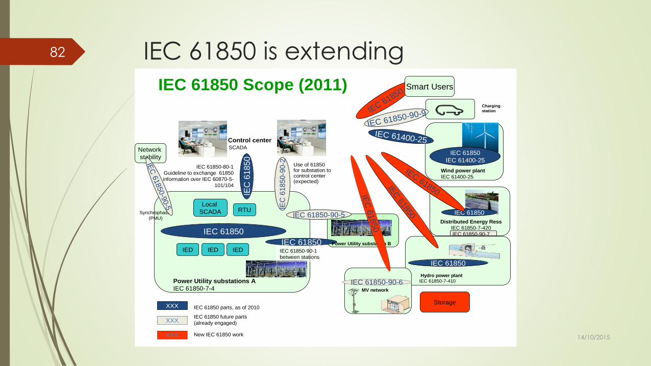
IEC 61850 is extending82
IEC 61850 Scope (2011)
Station
Distributed Energy Ress
IEC 61850-7-420
IEC 61850-90-7
Control centerSCADA
IEC
61850
IEC 61850-80-1
Guideline to exchange 61850
information over IEC 60870-5-
101/104
Wind power plant
IEC 61400-25
IEC 61400-25
IEC 61850-90-1
between stations
IEC 61850
IEC 61850
IED IED IED
RTULocal
SCADA
Power Utility substations A
IEC 61850-7-4
IEC 61850
Hydro power plant
IEC 61850-7-410
IEC 61850
IEC 61850
IEC 61400-25
IEC 61850-90-6MV network
Use of 61850for substation to control center(expected)
Power Utility substation B
IEC 61850
IEC
61850
IEC
61850
IEC
618
50
-90-2
Charging
station
Synchrophaser
(PMU)
Network
stability
IEC 61850-90-9
Smart Users
StorageIEC 61850 parts, as of 2010XXX
XXXIEC 61850 future parts
(already engaged)
XXX New IEC 61850 work
IEC 61850-90-5
IEC 61850
IEC
61850-9
0-5
14/10/2015

IEC 61850 extensions
1. Alarm management
2. Logic modeling
3. FACTS
4. Bulk generation
5. Revenue metering (COSEM)
6. Scheduling
7. Storage (battery)
8. Condition monitoring (UPS)
9. Feeder automation (Fault detectors - with TC38)
10.EV charging spot
11.Network management
12.Multiple use of DER
13.Communication from CC to SS
IEC 61850-90-7
Station
Distributed Energy
Resources
Control centerSCADA
IEC
61
85
0
IEC 61850-80-1
Guideline to exchange 61850
information over IEC 60870-5-101/104Wind power plant
IEC 61850-90-1
between stations
IEC 61850
IEC 61850
IED IED CTs/VTs
RTULocal
SCADA
Power Utility substations A
IEC 61850-7-4
IEC 61850-7-420
Hydro power plant
IEC 61850-7-410
IEC 61850
IEC 61400-25
IEC 61850-90-6
MV network
Use of 61850for substation to control center(expected)
Power Utility substation B
Charging station
Synchrophaser
(PMU)
Network
stability
Storage
IEC 61850 parts, as of 2013XXX
XXXIEC 61850 future parts (already
engaged) IEC 61850-90-15
IEC 61850-90-8
DER Integration
*: use of IEC 61850 over WAN can/will take advantage of
IEC 61850-80-1, IEC 61850-90-2 and IEC 61850-8-2 (web based) , and IEC 61850-90-12 (WAN)
14/10/2015
83

61850 road map (within TC57)84
14/10/2015

IEC 61850 documentation structure (reminder)85
Communication
requirement
for devices and
functions
IEC 61850-5
Basic
communicati
on structure
Principles
and models
IEC
61850-7-1
Configuration
description
language
IEC
61850-6
Application guide
IEC 61850-7-5
Domain specific LN and Data
object classes
IEC 61850-7-4xx
Common Data Classes
IEC 61850-7-3
Basic models, abstract services and basic types
IEC 61850-7-2
Mapping on network
(except sample values)
IEC 61850-8-xx
Sample Values mapping on
network
IEC 61850-9-xx
Technical
report
---
Guidelines
---
IEC
61850-90-xx
Glossary
IEC 61850-2
Introduction
IEC 61850-1
Conformance testing
IEC 61850-10
Implementation in IEDs and tools
General requirements
IEC 61850-3System and project management
IEC 61850-4
Technical
specification
---
Guidelines
---
IEC
61850-80-xx
Compatible LN and Data
object classes
IEC 61850-7-4
Domain specific application
guides
IEC 61850-7-5xx
14/10/2015

Additional deliverables86
Communic
ation
require-
ment
for devices
and
functions
IEC
61850-5
Basic
communi-
cation
structure
Principles
and
models
IEC
61850-7-
1
Configuration
description
language
IEC
61850-6
Product-specific profiles
Product specific LN and Data
object classes
xxxxx
Common Data Classes
IEC 61850-7-3
Basic models, abstract services and basic types
IEC 61850-7-2
Mapping on network
(except sample values)
IEC 61850-8-xx
Sample Values mapping on
network
IEC 61850-9-xx
Conformance testing
IEC 61850-10
Implementation in IEDs and tools
Glossary
IEC 61850-2
Introduction
IEC 61850-1
General requirements
IEC 61850-3System and project management
IEC 61850-4
Technical
specification
---
Guidelines
---
IEC
61850-80-1
Compatible LN and Data
object classes
IEC 61850-7-4xx
Protocol
---
IEC
60870-5-101
60870-5-104
Cases of
use of a
given
product
Product Profiles conformance testing
P3
P1
P2
P4
14/10/2015

How to manage extensions ?
To sum up87 uc Product specialisation
Complement IEC
61850 usage to
support "product"
integration
Get the knowledge of
the existing 61850
content
List the main cases
of use of the product
Identify possible
61850 gaps
Define product
profile(s) - if needed
Define a product
namespace - if
needed
Get a model manager
nominated
Propose 61850 data
model extensions
Get the proposed
model rev iewed
Publish a namespace
extension
Define
interoperability
objectiv es
Define typical
classes of products
(per set of functions)
Publish profile(s)
Product profile
testing
«include»
«include»
«include»
«include»
«include»
«precedes»
«precedes»
«precedes»
«include»
«include» «include» «include»
«precedes» «precedes»
«precedes»
«precedes»
«precedes»
«include» «include»
«precedes»
«include»
«precedes»
14/10/2015

Guideline for Technical Committees
and Working Groups on Using IEC
618501) Scope
The guide is for working groups (in / out side TC57) that intend to use IEC 61850 as a base standard within the scope of their work. The document shall help to identify the required steps in applying IEC 61850 for standardization work and shall provide guidelines for the individual steps.
Within that scope, the document addresses the following topics.
For the usage of IEC 61850 for new domains, the initial analysis how IEC 61850 can be used and what extensions may be required. The results of that step may be documented in a technical report.
The extension of the IEC 61850 object models for new domains. The typical work associated with that is, to identify existing logical nodes that can be reused with or without extensions and to define new logical nodes.
Product standards for products that have an interface based on IEC 61850.
IEC 61850 profiles for domains.
88
14/10/2015

Guide, Table of contents (1)2) How to use IEC 61850 for a domain
Data Model
Check existing logical nodes
Identify usable LNs
Identify extension requirements
Identify new LNs
Identify requirements to extend CDCs
Communication
Check services; identify services to be used; identify need for new services
Identify requirements on communication network topology, redundancy, reliability
Engineering
How to apply engineering; new requirements?
Document with a technical report
Security
89
14/10/2015

Guide, Table of contents (2)3) Guideline for extension of IEC 61850 Object Models
Principle modeling concepts
Detailed modeling guidelines
4) Product standards for products with IEC 61850 interface
Recommended elements of a product standard
Additional specifications – nameplate; logical devices,
datasets, control blocks, etc
5) IEC 61850 profiles for domains
Elements of a profile
Profile / a product standard
90
14/10/2015
Discussion & ExperienceQuestions ?
14/10/2015
91