prototype of iec 61850
TRANSCRIPT
IEC 61850 - Communication Networks and Systems in Substations:An Overview of Computer Science
Jianqing Zhang and Carl A. Gunter
University of Illinois at Urbana-Champaign
• Overview
• Data modeling approach
• Communication model
• Communication service mapping
• Sampled measured values
• Configuration description language
• Conclusion
• Reference
Agenda
2
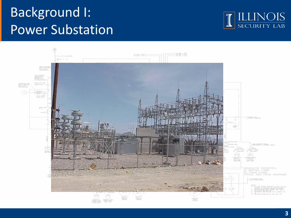
Background I:Power Substation
3
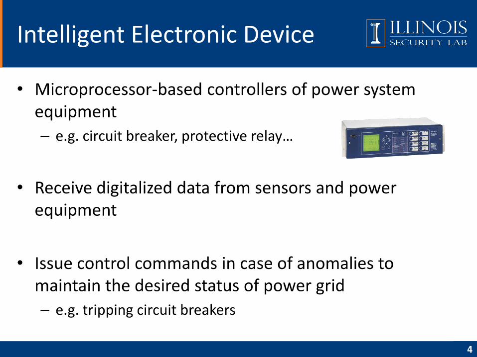
• Microprocessor-based controllers of power system equipment
– e.g. circuit breaker, protective relay…
• Receive digitalized data from sensors and power equipment
• Issue control commands in case of anomalies to maintain the desired status of power grid
– e.g. tripping circuit breakers
Intelligent Electronic Device
4
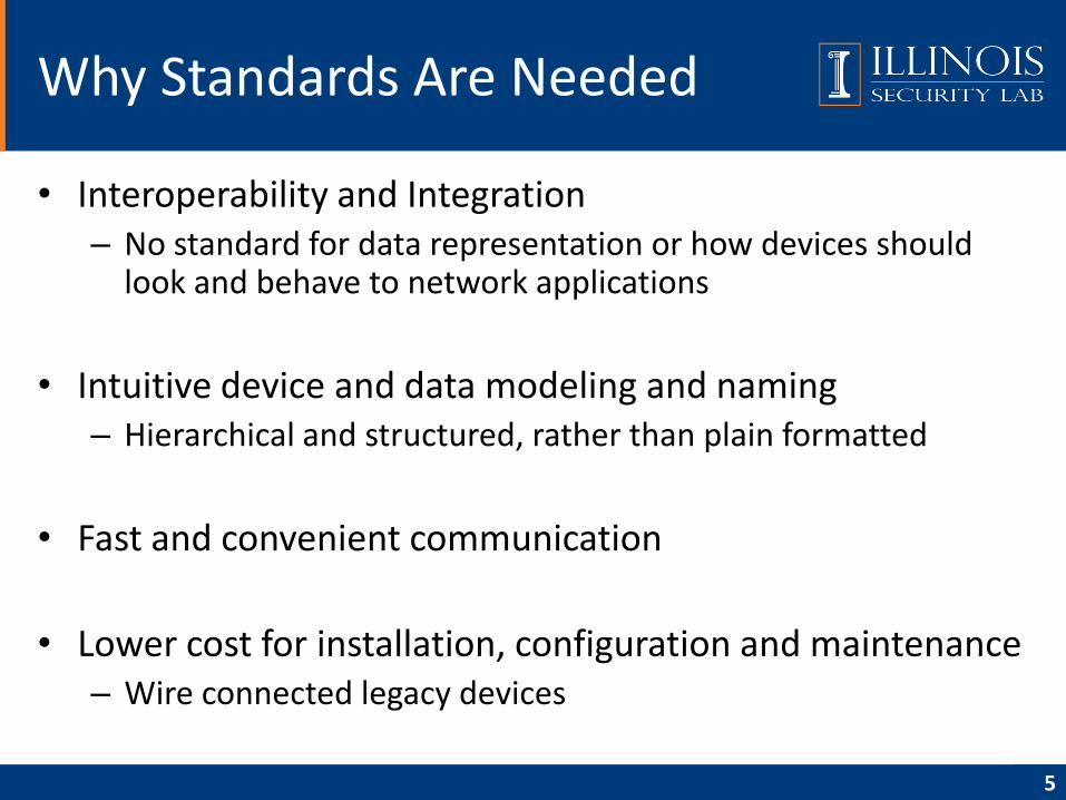
• Interoperability and Integration– No standard for data representation or how devices should
look and behave to network applications
• Intuitive device and data modeling and naming– Hierarchical and structured, rather than plain formatted
• Fast and convenient communication
• Lower cost for installation, configuration and maintenance– Wire connected legacy devices
Why Standards Are Needed
5
History of IEC 61850
6
IEC 61850
GOAL: One International Standard
UCA: Utility Communication Architecture
• Protocols
• Data models
• Abstract service definitions
IEC 60870-5
• A communication profile for sending basic telecontrol
messages between two systems
• Based on permanent directly connected data circuits
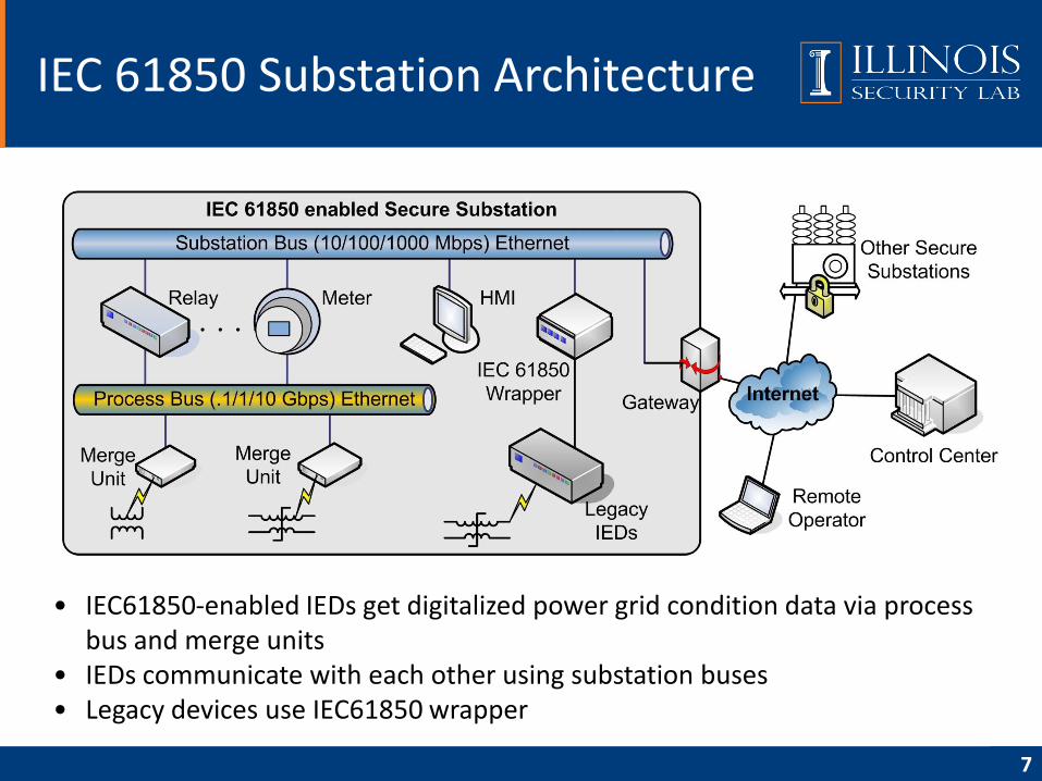
IEC 61850 Substation Architecture
7
• IEC61850-enabled IEDs get digitalized power grid condition data via process bus and merge units
• IEDs communicate with each other using substation buses• Legacy devices use IEC61850 wrapper
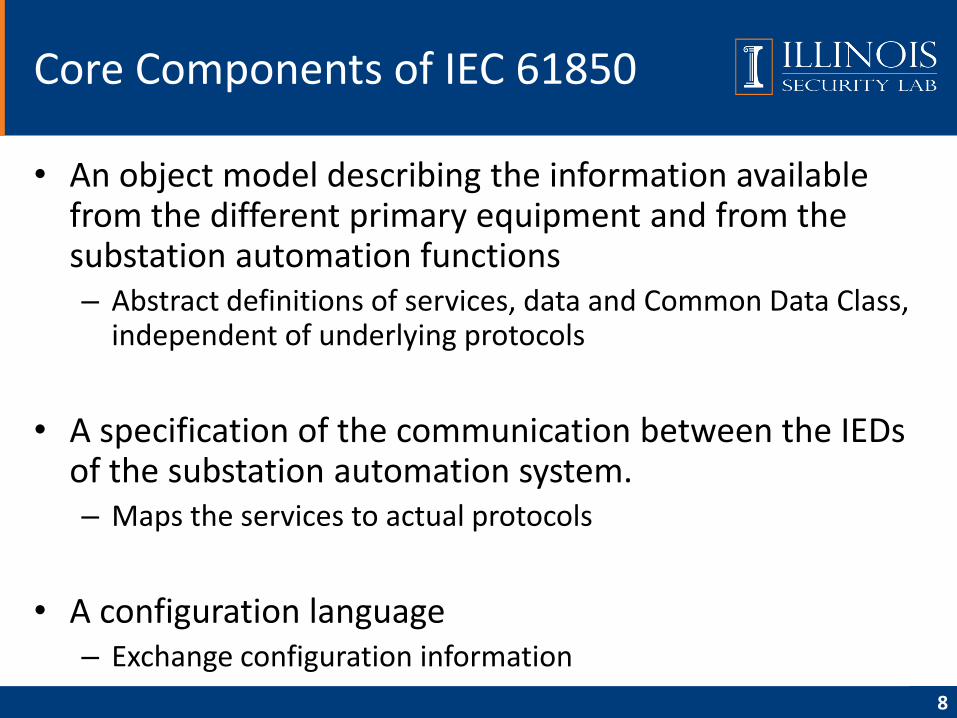
• An object model describing the information available from the different primary equipment and from the substation automation functions– Abstract definitions of services, data and Common Data Class,
independent of underlying protocols
• A specification of the communication between the IEDs of the substation automation system.– Maps the services to actual protocols
• A configuration language– Exchange configuration information
Core Components of IEC 61850
8
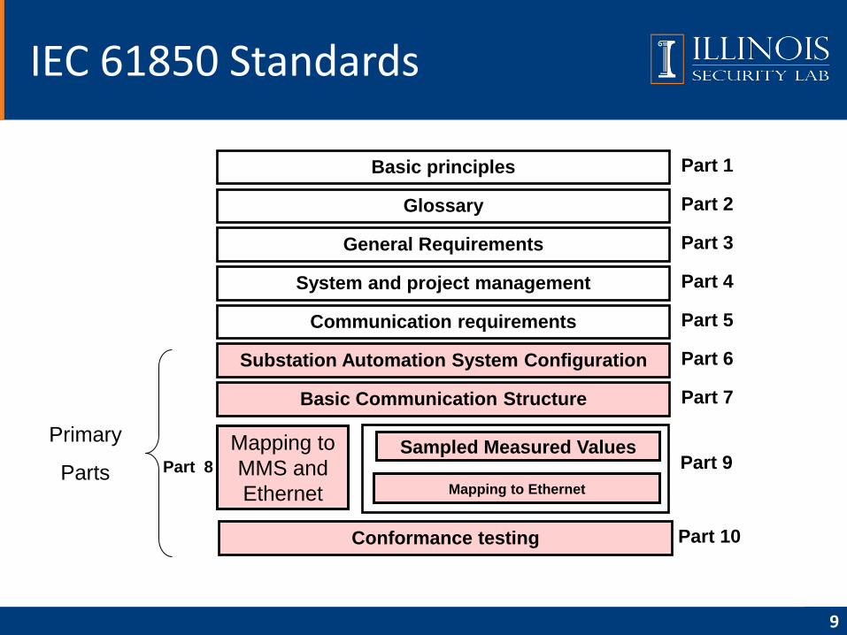
IEC 61850 Standards
9
Basic principles Part 1
Glossary Part 2
General Requirements Part 3
System and project management Part 4
Communication requirements Part 5
Substation Automation System Configuration Part 6
Basic Communication Structure Part 7
Part 9Sampled Measured Values
Conformance testing Part 10
Mapping to Ethernet
Mapping to
MMS and
Ethernet
Primary
Parts Part 8
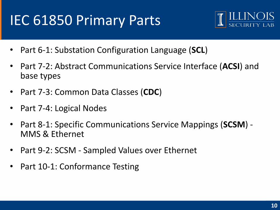
• Part 6-1: Substation Configuration Language (SCL)
• Part 7-2: Abstract Communications Service Interface (ACSI) and base types
• Part 7-3: Common Data Classes (CDC)
• Part 7-4: Logical Nodes
• Part 8-1: Specific Communications Service Mappings (SCSM) -MMS & Ethernet
• Part 9-2: SCSM - Sampled Values over Ethernet
• Part 10-1: Conformance Testing
IEC 61850 Primary Parts
10
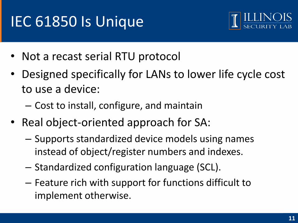
• Not a recast serial RTU protocol
• Designed specifically for LANs to lower life cycle cost to use a device:
– Cost to install, configure, and maintain
• Real object-oriented approach for SA:
– Supports standardized device models using names instead of object/register numbers and indexes.
– Standardized configuration language (SCL).
– Feature rich with support for functions difficult to implement otherwise.
IEC 61850 Is Unique
11
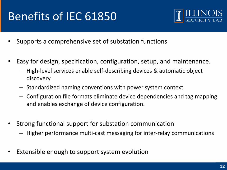
• Supports a comprehensive set of substation functions
• Easy for design, specification, configuration, setup, and maintenance.
– High-level services enable self-describing devices & automatic object discovery
– Standardized naming conventions with power system context
– Configuration file formats eliminate device dependencies and tag mapping and enables exchange of device configuration.
• Strong functional support for substation communication
– Higher performance multi-cast messaging for inter-relay communications
• Extensible enough to support system evolution
Benefits of IEC 61850
12
• Overview
• Data modeling approach
• Communication model
• Communication service mapping
• Sampled measured values
• Configuration description language
• Conclusion
• Reference
Agenda
13
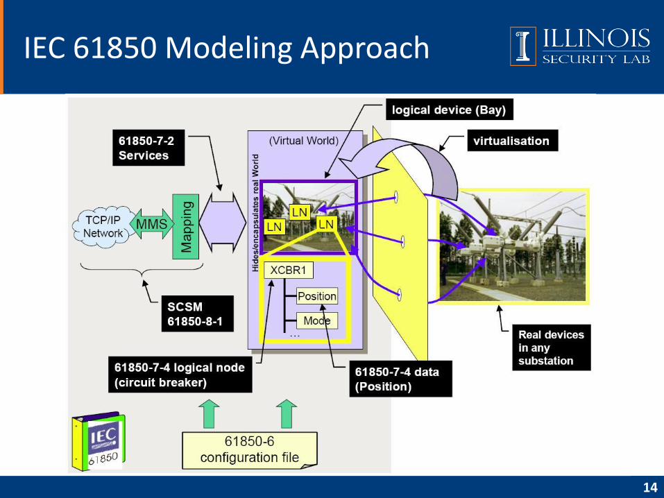
IEC 61850 Modeling Approach
14
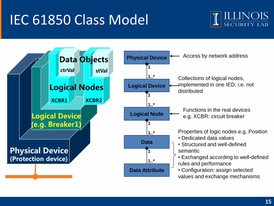
IEC 61850 Class Model
15
Physical Device(Protection device)
Logical Device(e.g. Breaker1)
XCBR1 XCBR2
ctrVal
Logical Nodes
stVal
Data ObjectsAccess by network address
Collections of logical nodes,
implemented in one IED, i.e. not
distributed
Physical Device
Logical Device
Logical Node
1..*
1..*
1
1
Data
1..*
1
Data Attribute
1..*
1
Functions in the real devices
e.g. XCBR: circuit breaker
Properties of logic nodes e.g. Position
• Dedicated data values
• Structured and well-defined
semantic
• Exchanged according to well-defined
rules and performance
• Configuration: assign selected
values and exchange mechanisms
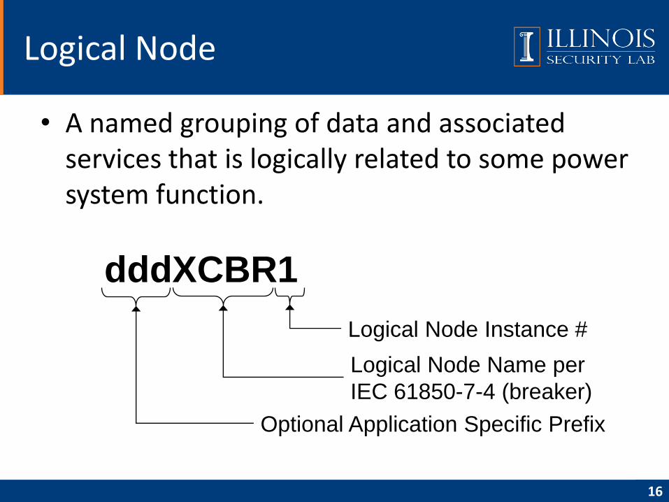
• A named grouping of data and associated services that is logically related to some power system function.
Logical Node
16
dddXCBR1
Optional Application Specific Prefix
Logical Node Name per
IEC 61850-7-4 (breaker)
Logical Node Instance #
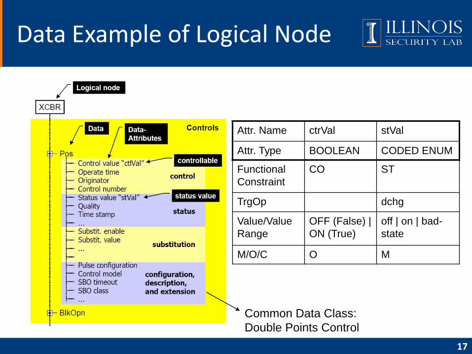
Attr. Name ctrVal stVal
Attr. Type BOOLEAN CODED ENUM
Functional
Constraint
CO ST
TrgOp dchg
Value/Value
Range
OFF (False) |
ON (True)
off | on | bad-
state
M/O/C O M
17
Data Example of Logical Node
Common Data Class:
Double Points Control
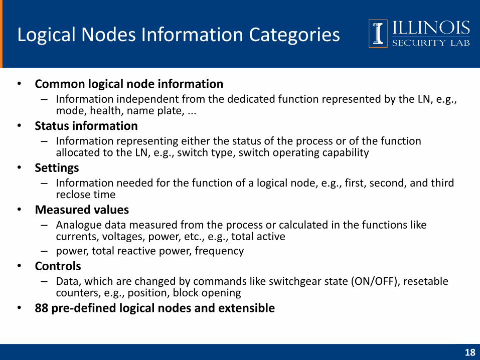
• Common logical node information– Information independent from the dedicated function represented by the LN, e.g.,
mode, health, name plate, ...
• Status information– Information representing either the status of the process or of the function
allocated to the LN, e.g., switch type, switch operating capability
• Settings– Information needed for the function of a logical node, e.g., first, second, and third
reclose time
• Measured values– Analogue data measured from the process or calculated in the functions like
currents, voltages, power, etc., e.g., total active– power, total reactive power, frequency
• Controls– Data, which are changed by commands like switchgear state (ON/OFF), resetable
counters, e.g., position, block opening
• 88 pre-defined logical nodes and extensible
Logical Nodes Information Categories
18
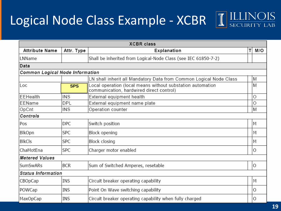
Logical Node Class Example - XCBR
19
SPS
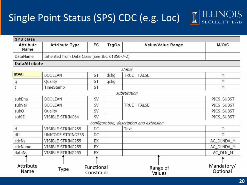
Single Point Status (SPS) CDC (e.g. Loc)
20
AttributeName Type Functional
ConstraintRange of
Values
Mandatory/Optional
stVal
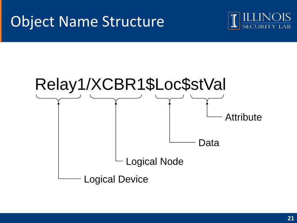
Object Name Structure
21
Relay1/XCBR1$Loc$stVal
Logical Device
Logical Node
Data
Attribute
• Overview
• Data modeling approach
• Communication model
• Communication service mapping
• Sampled measured values
• Configuration description language
• Conclusion
• Reference
Agenda
22
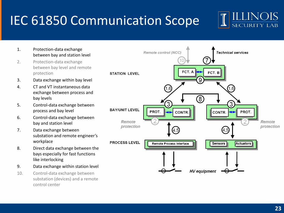
1. Protection-data exchange between bay and station level
2. Protection-data exchange between bay level and remote protection
3. Data exchange within bay level
4. CT and VT instantaneous data exchange between process and bay levels
5. Control-data exchange between process and bay level
6. Control-data exchange between bay and station level
7. Data exchange between substation and remote engineer’s workplace
8. Direct data exchange between the bays especially for fast functions like interlocking
9. Data exchange within station level
10. Control-data exchange between substation (devices) and a remote control center
IEC 61850 Communication Scope
23
• None timing critical message transmitting
• Used for configuration, maintenance, log…
• Three basic components
– A set of objects
– A set of services to manipulate and access those objects
– A base set of data types for describing objects
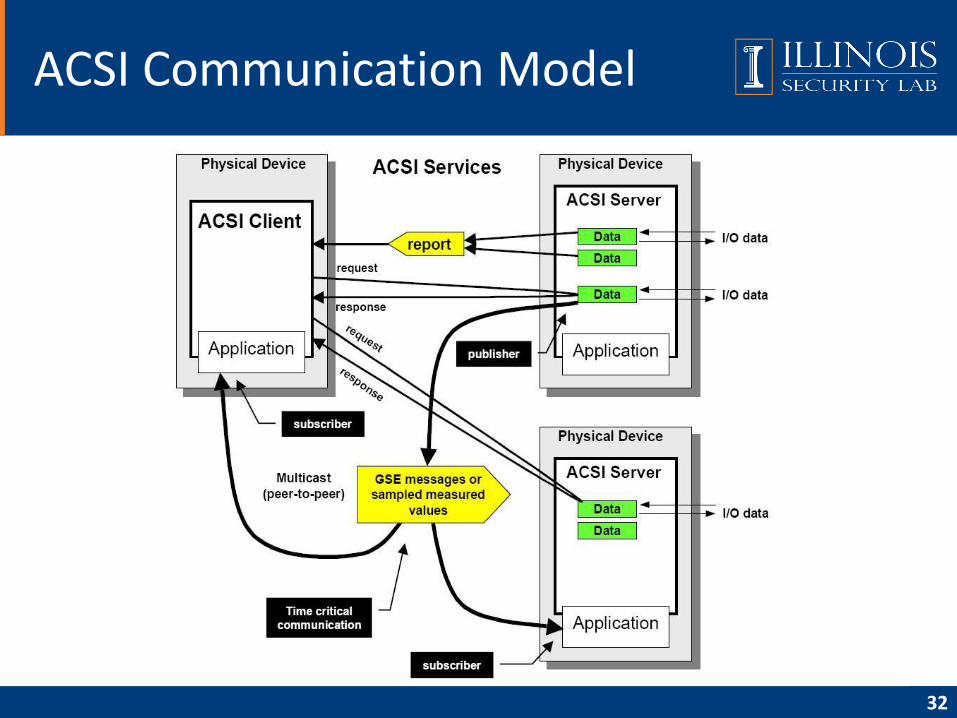
ACSI: Abstract Communications Service Interface
24
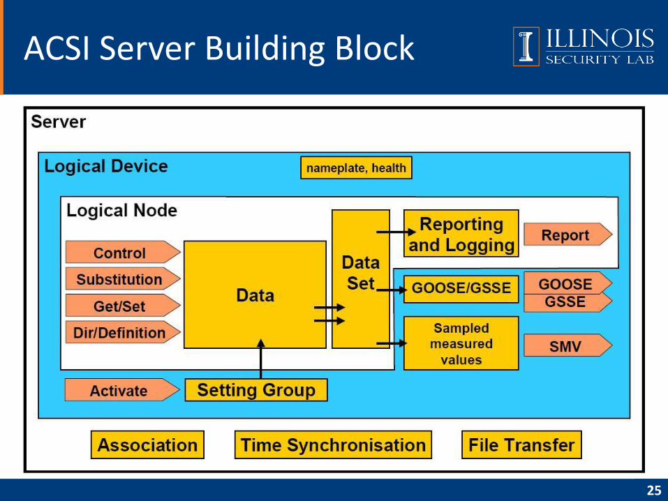
ACSI Server Building Block
25
• SERVER– Represents the external visible behavior of a (physical) device
– Communicate with a client
– Send information to peer devices
• LOGICAL-DEVICE (LD)– Contains the information produced and consumed by a group of domain-specific application
functions, which are defined as LOGICAL-NODEs
• LOGICAL-NODE (LN)– Contains the information produced and consumed by a domain specific application function
• DATA– Status and meta-information of object it presents in substation
– Provide means to specify typed information
Basic Information Models
26
• DATA-SET– The grouping of data and data attributes
– A view of DATA
• SETTING-GROUP– How to switch from one set of setting values to another one
– How to edit setting groups
• REPORT and LOG– Describe the conditions for generating reports and logs based on parameters set by the client
– Reports may be sent immediately or deferred
– Logs can be queried for later retrieval
• Generic Substation Event (GSE) control block (GSSE/GOOSE)– Supports a fast and reliable system-wide distribution of input and output data values
• Sampled Values Transmission control block– Fast and cyclic transfer of samples
Services Operating on Data
27
• Control
– Provide client mechanisms to control the DATA related to
external devices, control outputs, or other internal functions
• Substitution
– Support replacement of a process value (measurands of
analogue values or status values) by another value
• Get/Set
– Retrieve or write particular DataAttribute Values
• Dir/Definition
– Retrieve ObjectReferences and definitions of all sub-objects.
Services Operating on Data (cont.)
28
• Association– How the communication between the various types of devices
is achieved
– Two-party and Multicast
– Access Control
• Time Synchronization– Provide the UTC synchronized time to devices and system
• File Transfer– Defines the exchange of large data blocks such as programs
Other Services
29
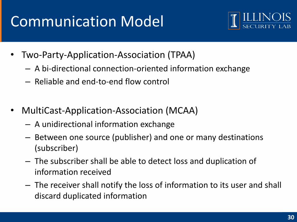
• Two-Party-Application-Association (TPAA)
– A bi-directional connection-oriented information exchange
– Reliable and end-to-end flow control
• MultiCast-Application-Association (MCAA)
– A unidirectional information exchange
– Between one source (publisher) and one or many destinations (subscriber)
– The subscriber shall be able to detect loss and duplication of information received
– The receiver shall notify the loss of information to its user and shall discard duplicated information
Communication Model
30
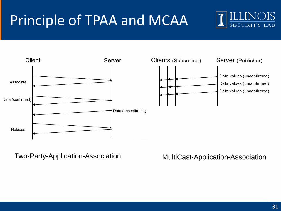
Principle of TPAA and MCAA
31
Two-Party-Application-Association MultiCast-Application-Association
ACSI Communication Model
32
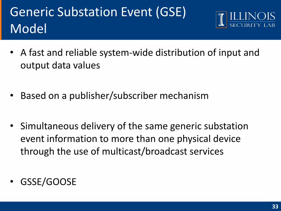
• A fast and reliable system-wide distribution of input and output data values
• Based on a publisher/subscriber mechanism
• Simultaneous delivery of the same generic substation event information to more than one physical device through the use of multicast/broadcast services
• GSSE/GOOSE
Generic Substation Event (GSE) Model
33
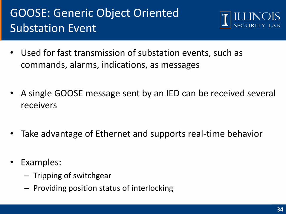
• Used for fast transmission of substation events, such as commands, alarms, indications, as messages
• A single GOOSE message sent by an IED can be received several receivers
• Take advantage of Ethernet and supports real-time behavior
• Examples:
– Tripping of switchgear
– Providing position status of interlocking
GOOSE: Generic Object Oriented Substation Event
34
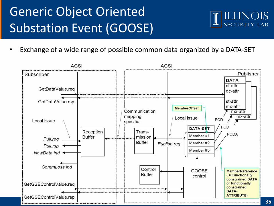
• Exchange of a wide range of possible common data organized by a DATA-SET
Generic Object Oriented Substation Event (GOOSE)
35
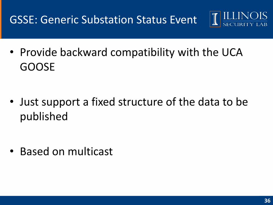
• Provide backward compatibility with the UCA GOOSE
• Just support a fixed structure of the data to be published
• Based on multicast
GSSE: Generic Substation Status Event
36
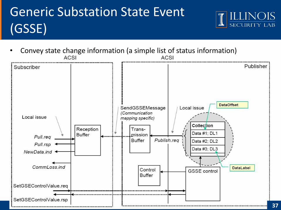
• Convey state change information (a simple list of status information)
Generic Substation State Event (GSSE)
37
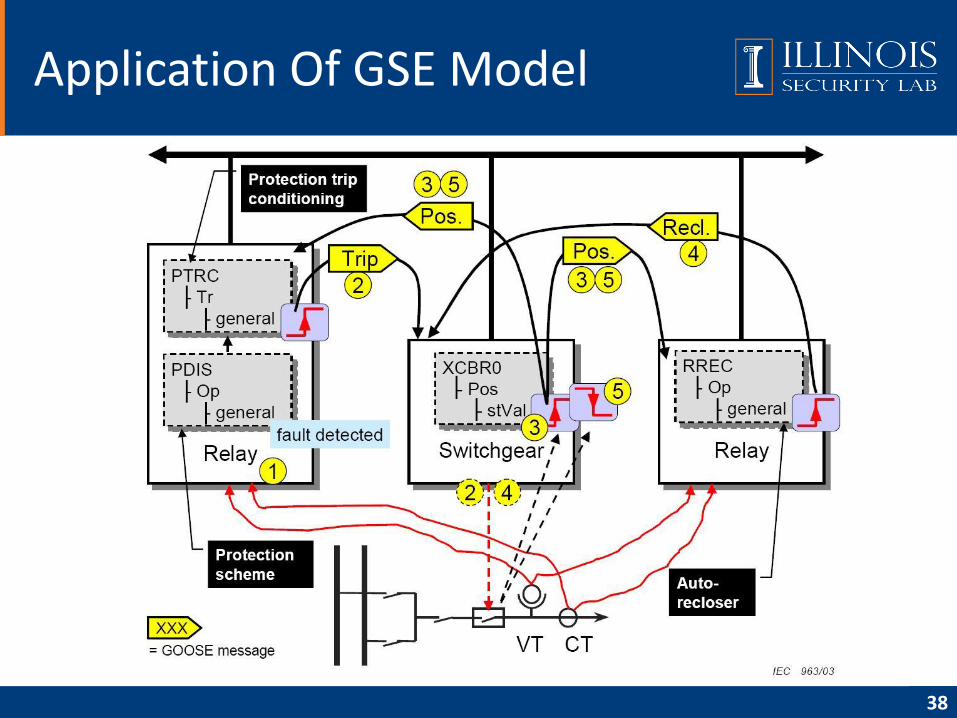
Application Of GSE Model
38
1. PDIS (distance protection) detects a fault
2. PTRC issues a <Trip> command to XCBR0 (circuit break); the switchgear opens the circuit breaker;
3. The new status information is immediately sent; the reporting model may report the change;
4. RREC (auto-reclosing) issues <Reclose> to XCBR0 according to the configured behavior;
5. XCBR0 receives the GOOSE message with the value <Reclose>; the switchgear closes the circuit breaker. XCBR0 issues another GOOSE message with the new position value
Application of GSE Model (cont.)
39
• Overview
• Data modeling approach
• Communication model
• Communication service mapping
• Sampled measured values
• Configuration description language
• Conclusion
• Reference
Agenda
40
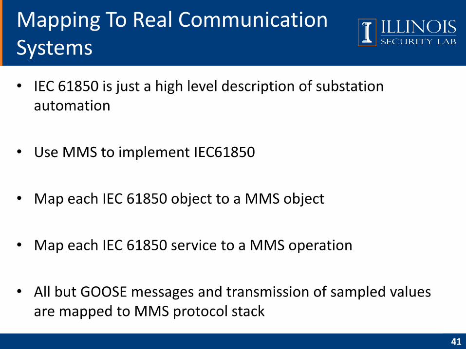
• IEC 61850 is just a high level description of substation automation
• Use MMS to implement IEC61850
• Map each IEC 61850 object to a MMS object
• Map each IEC 61850 service to a MMS operation
• All but GOOSE messages and transmission of sampled values are mapped to MMS protocol stack
Mapping To Real Communication Systems
41
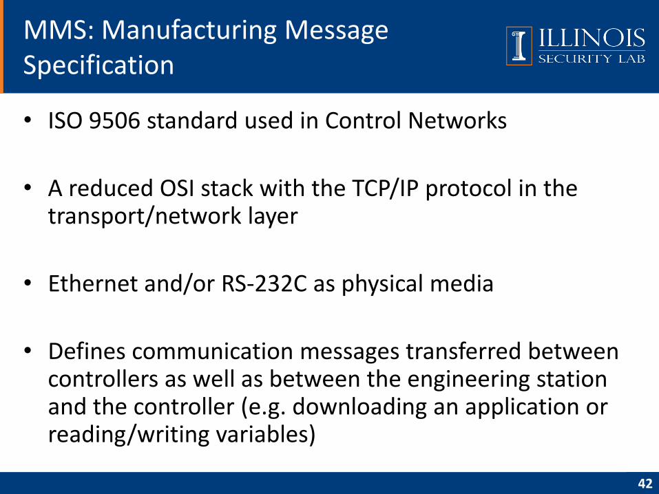
• ISO 9506 standard used in Control Networks
• A reduced OSI stack with the TCP/IP protocol in the transport/network layer
• Ethernet and/or RS-232C as physical media
• Defines communication messages transferred between controllers as well as between the engineering station and the controller (e.g. downloading an application or reading/writing variables)
MMS: Manufacturing Message Specification
42
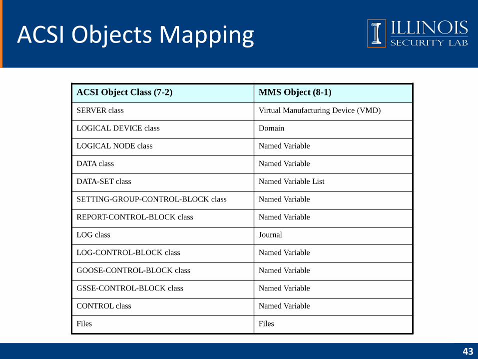
ACSI Objects Mapping
43
ACSI Object Class (7-2) MMS Object (8-1)
SERVER class Virtual Manufacturing Device (VMD)
LOGICAL DEVICE class Domain
LOGICAL NODE class Named Variable
DATA class Named Variable
DATA-SET class Named Variable List
SETTING-GROUP-CONTROL-BLOCK class Named Variable
REPORT-CONTROL-BLOCK class Named Variable
LOG class Journal
LOG-CONTROL-BLOCK class Named Variable
GOOSE-CONTROL-BLOCK class Named Variable
GSSE-CONTROL-BLOCK class Named Variable
CONTROL class Named Variable
Files Files
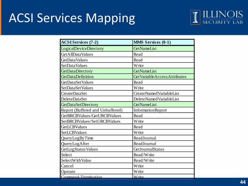
ACSI Services Mapping
44
ACSI Services (7-2) MMS Services (8-1)
LogicalDeviceDirectory GetNameList
GetAllDataValues Read
GetDataValues Read
SetDataValues Write
GetDataDirectory GetNameList
GetDataDefinition GetVariableAccessAttributes
GetDataSetValues Read
SetDataSetValues Write
CreateDataSet CreateNamedVariableList
DeleteDataSet DeleteNamedVariableList
GetDataSetDirectory GetNameList
Report (Buffered and Unbuffered) InformationReport
GetBRCBValues/GetURCBValues Read
SetBRCBValues/SetURCBValues Write
GetLCBValues Read
SetLCBValues Write
QueryLogByTime ReadJournal
QueryLogAfter ReadJournal
GetLogStatusValues GetJournalStatus
Select Read/Write
SelectWithValue Read/Write
Cancel Write
Operate Write
Command-Termination Write
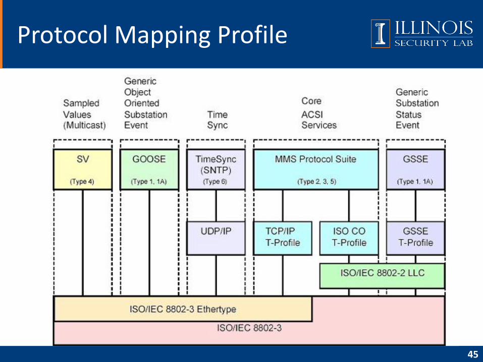
Protocol Mapping Profile
45
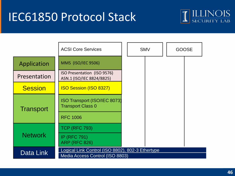
IEC61850 Protocol Stack
46
Data Link
Network
Transport
Session
Presentation
Application
Logical Link Control (ISO 8802), 802-3 Ethertype
Media Access Control (ISO 8803)
IP (RFC 791)
ARP (RFC 826)
TCP (RFC 793)
RFC 1006
ISO Transport (ISO/IEC 8073)
Transport Class 0
ISO Session (ISO 8327)
ISO Presentation (ISO 9576)ASN.1 (ISO/IEC 8824/8825)
MMS (ISO/IEC 9506)
SMV GOOSEACSI Core Services
• Overview
• Data modeling approach
• Communication model
• Communication service mapping
• Sampled measured values
• Configuration description language
• Conclusion
• Reference
Agenda
47
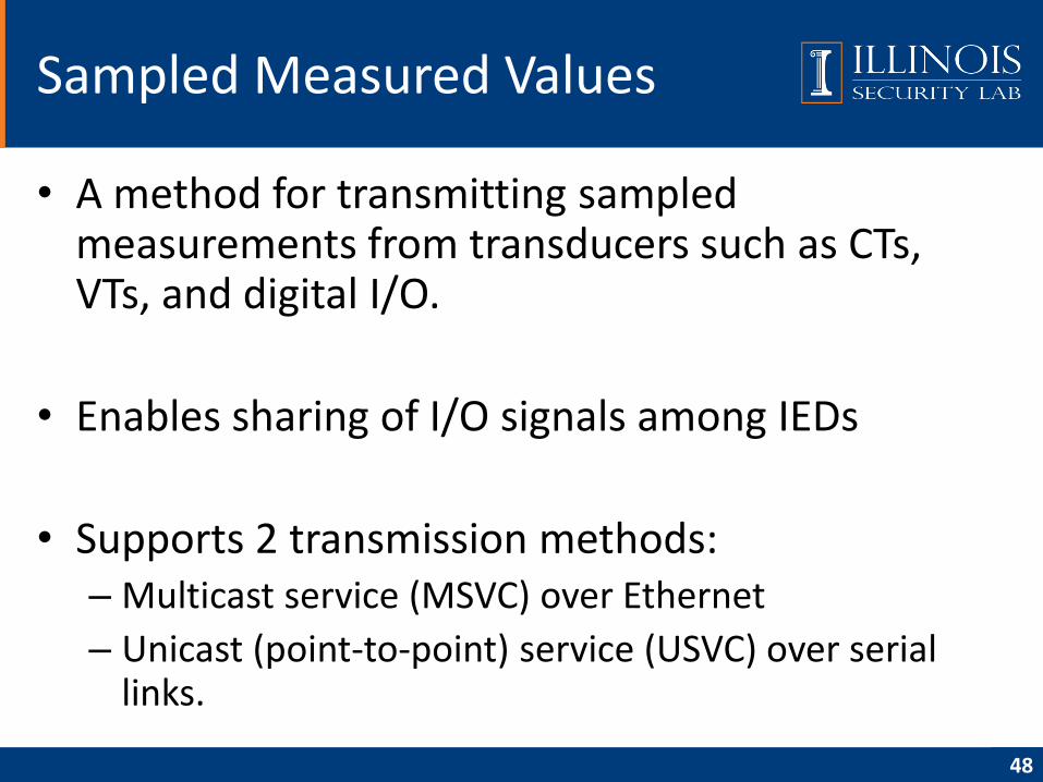
• A method for transmitting sampled measurements from transducers such as CTs, VTs, and digital I/O.
• Enables sharing of I/O signals among IEDs
• Supports 2 transmission methods:– Multicast service (MSVC) over Ethernet
– Unicast (point-to-point) service (USVC) over serial links.
Sampled Measured Values
48
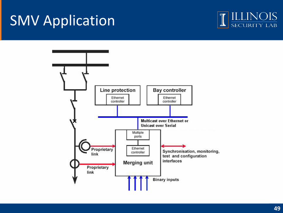
SMV Application
49
• Overview
• Data modeling approach
• Communication model
• Communication service mapping
• Sampled measured values
• Configuration description language
• Conclusion
• Reference
Agenda
50
• Purpose: interoperable exchange of
communication system configuration data
between an IED configuration tool and a system
configuration tool from different manufacturers.
• A formal description of
– Relations between substation automation system and
the switchyard
– Relations of the switchyard structure to the SAS
functions (logical nodes) configured on the IEDs
SCL: Substation Configuration Language
51
1. Functional specification input to SAS engineering– A system specification in terms of the single line diagram, and allocation of logical nodes
(LN) to parts and equipment of the single line to indicate the needed functionality.
2. IED capability description – results after IED pre-engineering– Pre-configured IEDs with a fixed number of logical nodes (LNs), but with no binding to a
specific process . may only be related to a very general process function part.
– Pre-configured IEDs with a pre-configured semantic for a process part of a certain structure, for example a double bus-bar GIS line feeder.
3. SA system description - result after SAS engineering– Complete process configuration with all IEDs bound to individual process functions and
primary equipment, enhanced by the access point connections and possible access paths in sub-networks for all possible clients.
– As item d) above, but additionally with all predefined associations and client server connections between logical nodes on data level. This is needed if an IED is not capable of dynamically building associations or reporting connections (either on the client or on the server side).
Intended Engineering Process With SCL
52
• Define an object model describing the IEDs, their communication connections, and their allocation to the switchyard (Part 7)
• Describe how this model shall be represented in a file to be exchanged between engineering tools in a standardized way (Part 6)
Approach
53
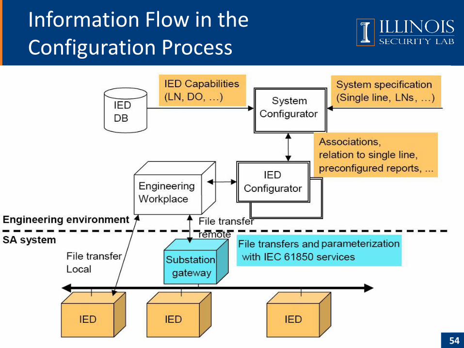
Information Flow in the Configuration Process
54
• IED Configurator
– A manufacturer-specific tool used to import or export SCL files
– Provides IED-specific settings and generates IED specific configuration files
– Loads the IED configuration into the IED
• System Configurator
– An IED independent system level tool used to import or export SCL files
– Imports configuration files from several IEDs, as needed for system level engineering
– Adds system information shared by different IEDs (by the configuration engineer)
– Generates a substation related configuration file, which may be fed back to the IED Configurator for system related IED configuration
– Reads a system specification file for example as a base for starting system engineering, or to compares it with an engineered system for the same substation.
Information Flow in the Configuration Process (cont.)
55
• The primary (power) system structure – Which primary apparatus functions are used
– How the apparatus are connected
• The communication system– How IEDs are connected to subnetworks and networks
– And at which of their communication access points (communication ports)
• The application level communication– How data is grouped into data sets for sending
– How IEDs trigger the sending and which service they choose, which input data from other IEDs is needed
• Each IED– The logical devices configured on the IED
– The logical nodes with class and type belonging to each logical device
– The reports and their data contents
– Logged data
– The (pre-configured) associations
• Instantiable logical node (LN) – Mandatory, optional and user defined DATA (here abbreviated DO) as well as optional services
SCL Object Model
56
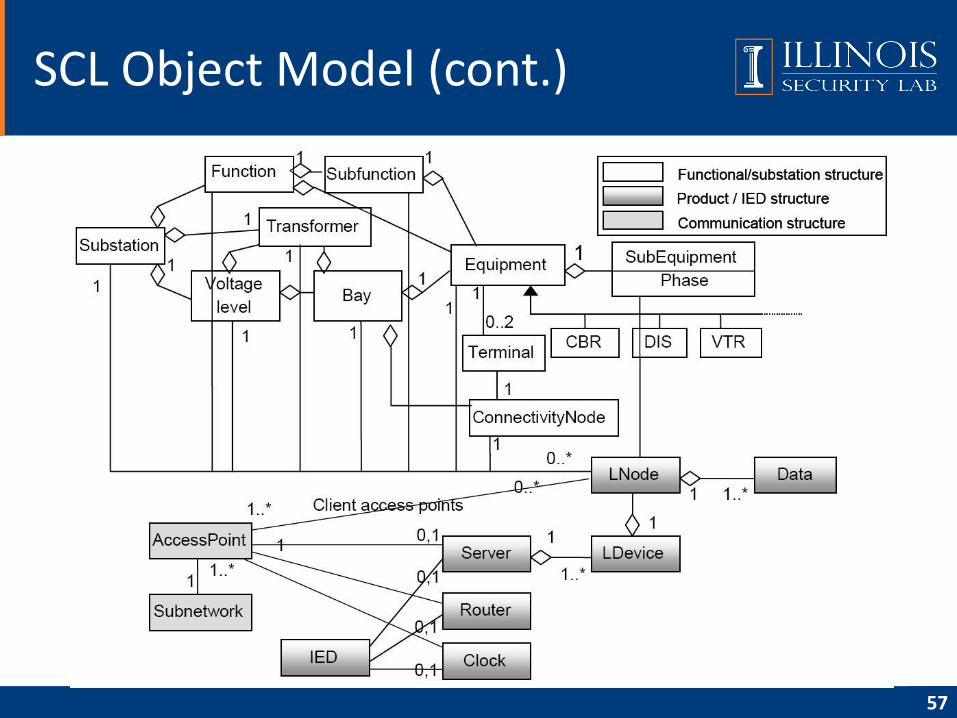
SCL Object Model (cont.)
57
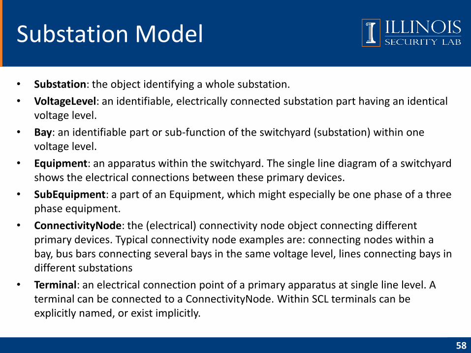
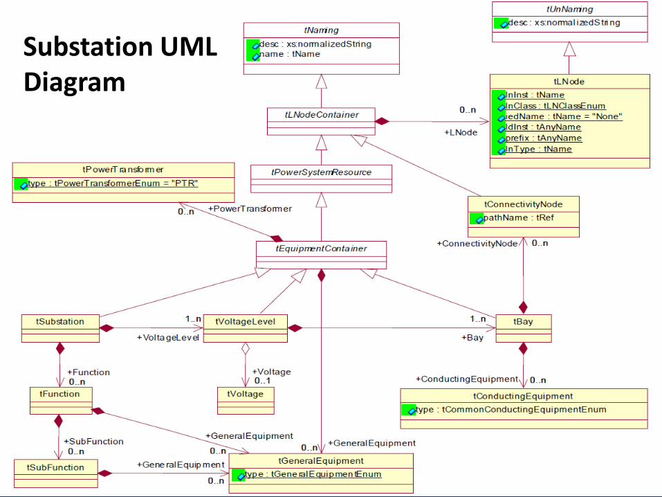
• Substation: the object identifying a whole substation.
• VoltageLevel: an identifiable, electrically connected substation part having an identical voltage level.
• Bay: an identifiable part or sub-function of the switchyard (substation) within one voltage level.
• Equipment: an apparatus within the switchyard. The single line diagram of a switchyard shows the electrical connections between these primary devices.
• SubEquipment: a part of an Equipment, which might especially be one phase of a three phase equipment.
• ConnectivityNode: the (electrical) connectivity node object connecting different primary devices. Typical connectivity node examples are: connecting nodes within a bay, bus bars connecting several bays in the same voltage level, lines connecting bays in different substations
• Terminal: an electrical connection point of a primary apparatus at single line level. A terminal can be connected to a ConnectivityNode. Within SCL terminals can be explicitly named, or exist implicitly.
Substation Model
58
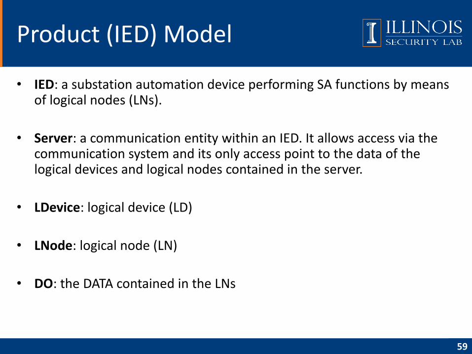
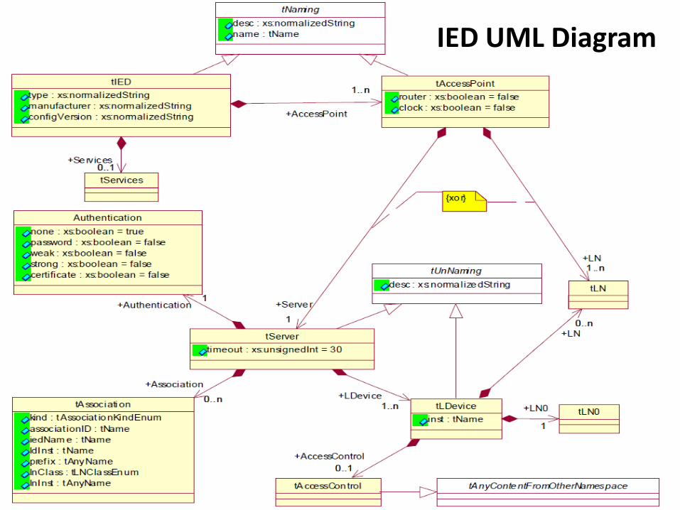
• IED: a substation automation device performing SA functions by means of logical nodes (LNs).
• Server: a communication entity within an IED. It allows access via the communication system and its only access point to the data of the logical devices and logical nodes contained in the server.
• LDevice: logical device (LD)
• LNode: logical node (LN)
• DO: the DATA contained in the LNs
Product (IED) Model
59
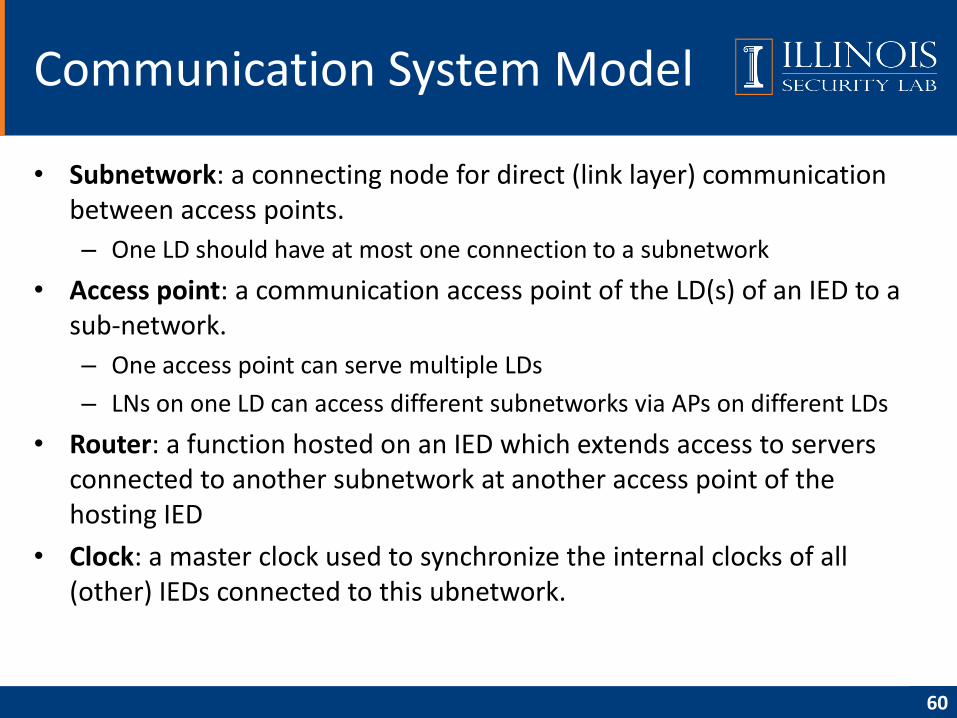
• Subnetwork: a connecting node for direct (link layer) communication between access points.
– One LD should have at most one connection to a subnetwork
• Access point: a communication access point of the LD(s) of an IED to a sub-network.
– One access point can serve multiple LDs
– LNs on one LD can access different subnetworks via APs on different LDs
• Router: a function hosted on an IED which extends access to servers connected to another subnetwork at another access point of the hosting IED
• Clock: a master clock used to synchronize the internal clocks of all (other) IEDs connected to this ubnetwork.
Communication System Model
60
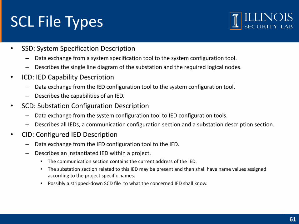
• SSD: System Specification Description– Data exchange from a system specification tool to the system configuration tool.
– Describes the single line diagram of the substation and the required logical nodes.
• ICD: IED Capability Description– Data exchange from the IED configuration tool to the system configuration tool.
– Describes the capabilities of an IED.
• SCD: Substation Configuration Description– Data exchange from the system configuration tool to IED configuration tools.
– Describes all IEDs, a communication configuration section and a substation description section.
• CID: Configured IED Description– Data exchange from the IED configuration tool to the IED.
– Describes an instantiated IED within a project.
• The communication section contains the current address of the IED.
• The substation section related to this IED may be present and then shall have name values assigned according to the project specific names.
• Possibly a stripped-down SCD file to what the concerned IED shall know.
SCL File Types
61
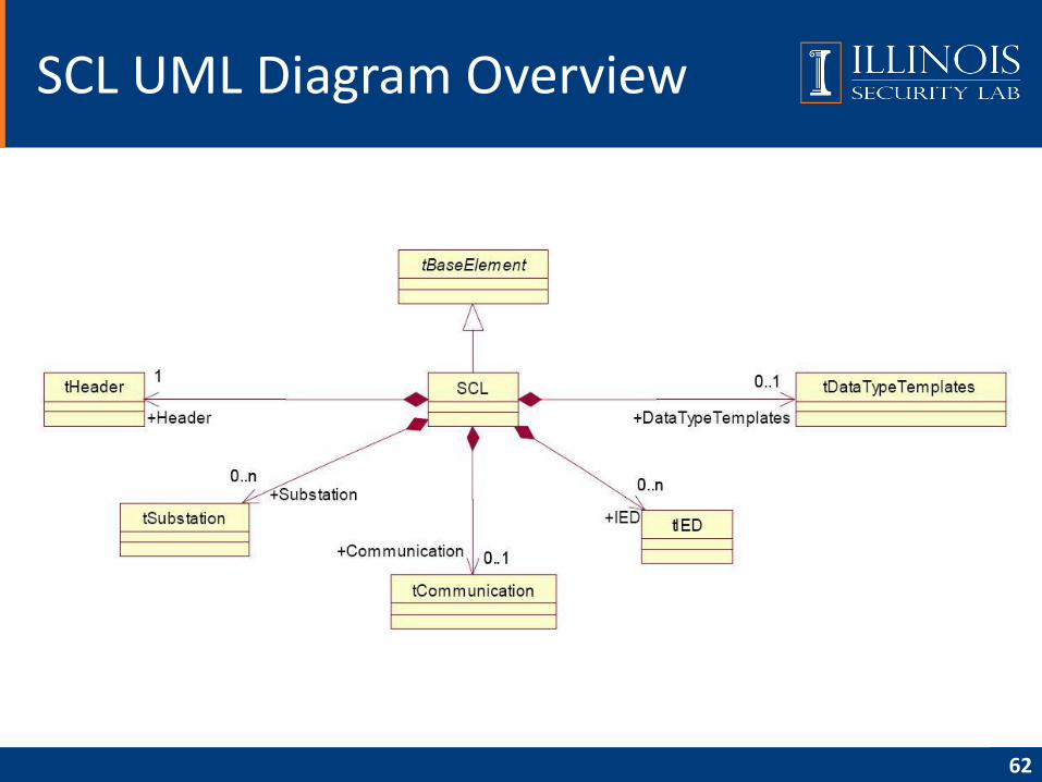
SCL UML Diagram Overview
62
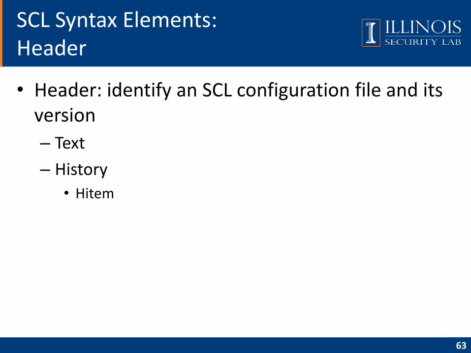
• Header: identify an SCL configuration file and its version
– Text
– History
• Hitem
SCL Syntax Elements:Header
63
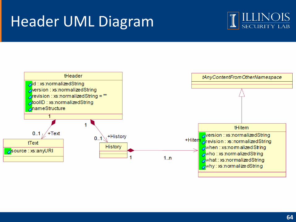
Header UML Diagram
64
• Substation: describes the functional structure of a substation; identifies the primary devices and their electrical connections
SCL Syntax Elements:Header and Substation
65
66
Substation UML Diagram
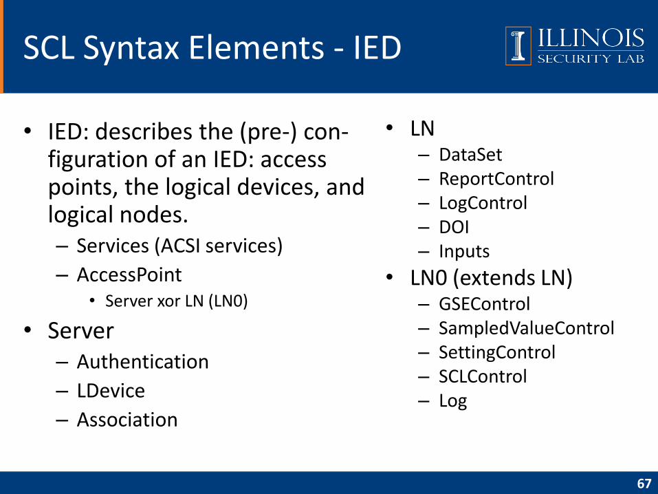
• IED: describes the (pre-) con-figuration of an IED: access points, the logical devices, and logical nodes.– Services (ACSI services)
– AccessPoint• Server xor LN (LN0)
• Server– Authentication
– LDevice
– Association
• LN– DataSet– ReportControl– LogControl– DOI– Inputs
• LN0 (extends LN)– GSEControl– SampledValueControl– SettingControl– SCLControl– Log
67
SCL Syntax Elements - IED
68
IED UML Diagram
• Communication
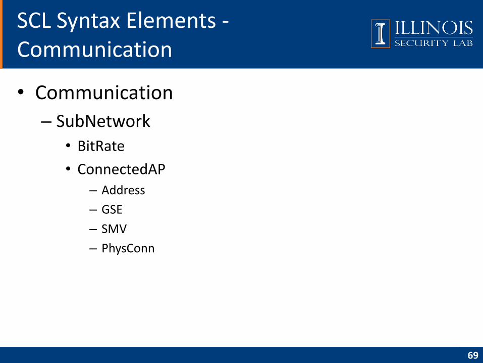
– SubNetwork
• BitRate
• ConnectedAP– Address
– GSE
– SMV
– PhysConn
SCL Syntax Elements -Communication
69
70
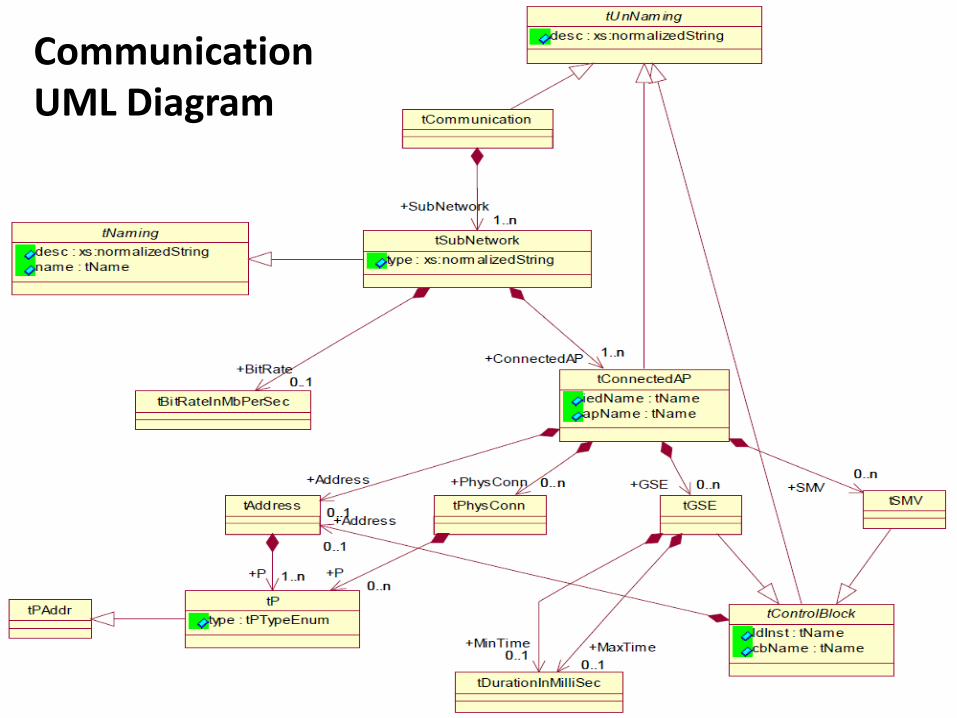
CommunicationUML Diagram
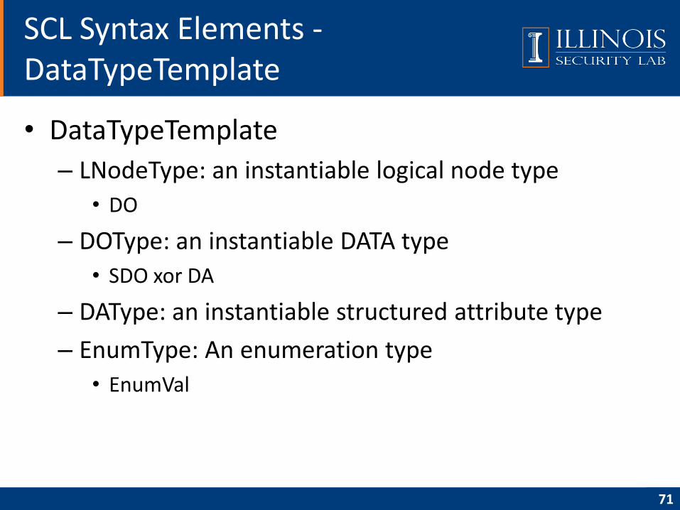
• DataTypeTemplate
– LNodeType: an instantiable logical node type
• DO
– DOType: an instantiable DATA type
• SDO xor DA
– DAType: an instantiable structured attribute type
– EnumType: An enumeration type
• EnumVal
SCL Syntax Elements -DataTypeTemplate
71
72
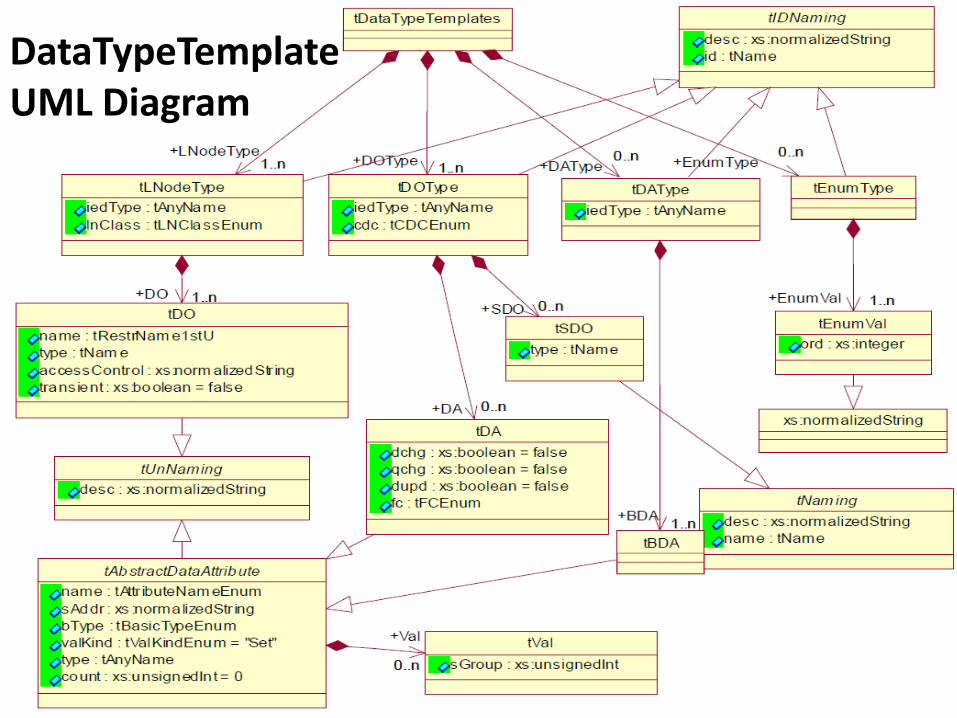
DataTypeTemplateUML Diagram
• Overview
• Data modeling approach
• Communication model
• Communication service mapping
• Sampled measured values
• Configuration description language
• Conclusion
• Reference
Agenda
73
• IEC 61850 is a migration from the analog world to the digital world for substation
– Standardization of data names
– Creation of a comprehensive set of services
– Implementation over standard protocols and hardware
– Definition of a process bus.
• Multi-vendor interoperability has been demonstrated
• Discussions are underway to utilize IEC 61850 as the substation to control center communication protocol
• IEC 61850 will become the protocol of choice as utilities migrate to network solutions for the substations and beyond.
Conclusion
74
• IEC 61850 Communication Networks and Systems In Substations, Technical Committee 57, International Electrotechnical Commission,
• Secure Intelligent Electronic Devices (SIEDs). C. A. Gunter, S. T. King, J. Zhang. PSERC 2007
• Overview of IEC 61850 and Benefits, R. E. Mackiewicz. PES TD 2005/2006
• IEC 61850 Communication Networks and Systems In Substations: An Overview for Users. D. Baigent, M. Adamiak and R. Mackiewicz. SIPSEP 2004
Reference
75

ILLINOIS SECURITY LAB4309 Siebel Center for Computer Science201 N Goodwin AveUrbana, IL 61801Phone: (217)265-6758http://seclab.illinois.edu
Jianqing Zhang: [email protected]
Carl A. Gunter: [email protected]