iec 61850 fundamentals
TRANSCRIPT

© OMICRON
K02 03 20060309
IEC 61850 FundamentalsIEC 61850 Fundamentals
Dr. Alexander ApostolovLos Angeles, CA

© OMICRON
Communication in SubstationsCommunication in Substations• Centralized monitoring and control• With numerical relays (IEDs) substation automation has
become more popular and easy to install • Reduced hardwiring – saving time and effort on
commissioning and maintenance
Communications Architecture
HMI,s
Switchgear CTs & PTs
SubstationController (s)
SCADA ProtocolTo IMS/SCADA
ISDISD ISDISD
Switchgear CTs & PTs

© OMICRON
Communication in SubstationsCommunication in SubstationsSUBSTATION COMMUNICATION
Physical link Protocol
RS485 - copper
RS232 - copper
Ethernet - copper
Ethernet – optic
SPA
Courier
Profibus . . .
MODBUS
DNP3
IEC 60870
Proprietary
Open

© OMICRON
Existing Protocol LimitationsExisting Protocol Limitations• High engineering costs
• Each protocol had its own structure of representing data (approx. US $ 28 billion spent on application integration in 1998 – Forrester 1999.)
• Many protocols • Inter-operability was an issue.• Different levels of functionalities
• Use of proprietary protocol • limited use of multi-user products
• Each protocol supported Different standards followed in Europe and North America

© OMICRON“IEC61850 tutorial, CIGRE Sept 2003.” – Klaus Peter Brand
Market RequirementsMarket Requirements
• Global Market• Needs a global standard• Means a broad range of philosophies
• Mixing of devices, at least with copper cables
• Cost reduction by• Competition• Intelligence (functions)
© OMICRON“IEC61850 tutorial, CIGRE Sept 2003.” – Klaus Peter Brand
Market RequirementsMarket Requirements
• Cost reduction in• Investment• Operation
• Maintenance• Open standard, especially for the future
safe guard of investments

© OMICRON
European historical perspectiveEuropean historical perspective
• TC57 - Power systems management and associated information exchange
• IEC 60870-6 TASE 1 - ELCOM90TASE 2 - ICCP
• IEC 60870-5 101 telecontrol102 metering103 protection and control104 telecontrol over TCP

© OMICRON
European historical perspectiveEuropean historical perspective
• 1994 AHWG created 2 New Work Item Proposals:• Short term solution
• 103 = VDEW + Courier• Longer term solution
• IEC 61850

© OMICRON
American historical perspectiveAmerican historical perspective
• ANSI Market• MODBUS• MODBUS plus• DNP 3.0 level 2
• EPRI UCA 1.0 - TASE.2 (ICCP)2.0 - Substation Initiative

© OMICRON“UCA & 61850 for Dummies.” – Douglas Proudfoot
UCA 2.0 is dead, forget it!
IEEE TR 1550:1999
New Standards EmergeNew Standards Emerge

© OMICRON
FredFred

© OMICRON
LucyLucy

© OMICRON
Working Group MembersWorking Group Members

© OMICRON
Working Group MembersWorking Group Members

© OMICRON
Working Group MembersWorking Group Members

© OMICRON
Working Group MembersWorking Group Members

© OMICRON
Working Group MembersWorking Group Members

© OMICRON
Working Group MembersWorking Group Members

© OMICRON
IntroductionIntroduction
Is it really that simple ?
IEC 6185014 Parts
>1000 pages (English only !)10 years of development
REAL SUBSTATIONDifferent vendorsInteroperability
Easy specification

© OMICRON
IEC 61850 Standard - Organization

© OMICRON
IEC 61850: IEC 61850: Basic applications Basic applications and possible extensionsand possible extensions
Telecontrol of substations “sTCA”in discussion, IEC TC57 / Ad Hoc Working Group 07Addendum Power Quality, Monitoringunder way, IEC 57/624/NPProduct standard for switchgear equipmentunder way, IEC 62271-003Control and monitoring of wind power plants under way, IEC 61400-25Control and monitoring of distributed power stations under way, IEC 57/660/NP

© OMICRON
IEC 61850: IEC 61850: Basic applications Basic applications and possible extensionsand possible extensions
Control and monitoring of hydroelectric power plants under way, IEC 57/661/NPMetering (EPRI, IEEE), Gas, Waterin discussionSeveral other WG within:
IEEE PSRC H5: Setting, etc.UCA International: Testing, etc.CIGRE B5.11: Use of IEC 61850 in
substation, etc.DKE/VDN (Germany): Recommendations

© OMICRON
IEC 61850 IEC 61850 -- in briefin brief• Not just another bus system…• Goes far beyond almost all other
communication standards• It extends the way automation devices
“work together”• Defines WHAT to communicate and HOW to
communicate• Everything has a name• Configuration language for devices and
substations

© OMICRON
• Selects communication protocols• Applicable in substations and many other
domains• Wind power• Distributed Energy Resources• Hydro
IEC 61850 IEC 61850 -- in briefin brief

© OMICRON
IEC 61850 IEC 61850 -- ScopeScopeWG10: Functional Architecture and General Requirements
Level 2
Level 1
Level 0
SUBSTATION LEVEL FUNCTIONSSUBSTATION LEVEL FUNCTIONSTC57
- Control - Metering- Disturbance recorder- Misc. Functions
- Control - Metering- Disturbance recorder- Misc. Functions
Bay Unit
TC57
- Protection- Disturbance recorder
- Protection- Disturbance recorder
TC95ProtectionProtection
TC95
Switchgear andtransformer
Switchgear andtransformer
TC14, TC17
InstrumentaltransformersInstrumentaltransformers
TC38
Switchgear andtransformer
Switchgear andtransformer
TC14, TC17
InstrumentaltransformersInstrumentaltransformers
TC38
Technical servicesRemote control (NCC)

© OMICRON
Station BusStation Bus• WG11: Communication within and between Unit
and Station levels
Level 2
Level 1
Level 0
SUBSTATION LEVEL FUNCTIONSSUBSTATION LEVEL FUNCTIONSTC57
- Control - Metering- Disturbance recorder- Misc. Functions
- Control - Metering- Disturbance recorder- Misc. Functions
Bay Unit
TC57
- Protection- Disturbance recorder
- Protection- Disturbance recorder
TC95ProtectionProtection
TC95
Switchgear andtransformer
Switchgear andtransformer
TC14, TC17
InstrumentaltransformersInstrumentaltransformers
TC38
Switchgear andtransformer
Switchgear andtransformer
TC14, TC17
InstrumentaltransformersInstrumentaltransformers
TC38
Technical servicesRemote control (NCC)

© OMICRON
Process BusProcess Bus• WG12: Communication within and between Process
and Unit levels
Level 2
Level 1
Level 0
SUBSTATION LEVEL FUNCTIONSSUBSTATION LEVEL FUNCTIONSTC57
- Control - Metering- Disturbance recorder- Misc. Functions
- Control - Metering- Disturbance recorder- Misc. Functions
Bay Unit
TC57
- Protection- Disturbance recorder
- Protection- Disturbance recorder
TC95ProtectionProtection
TC95
Switchgear andtransformer
Switchgear andtransformer
TC14, TC17
InstrumentaltransformersInstrumentaltransformers
TC38
Switchgear andtransformer
Switchgear andtransformer
TC14, TC17
InstrumentaltransformersInstrumentaltransformers
TC38
Technical servicesRemote control (NCC)

© OMICRON
Standardized data modelsfor all applications
IEC 61850 StandardIEC 61850 Standard• Uses the strengths of the OSI 7 layer communication model • Station bus
• Communication between IED and master stations• Data polled by Master from IED (Buffered or un-buffered)• Inter IED data exchange through multi-cast GOOSE
messages• Process bus
• Communication between plant equipment and IEDs (switchgear, Instrument transformers)
• Exchange of sampled values• Bus separation is becoming less distinct

© OMICRON
Requirements of New StandardRequirements of New Standard
Free Configuration: The support of different philosophies and ability for free allocation of functions, i.e. it will work equally well for centralized (RTU like) or decentralized (SCS like) systems.
Interoperability: The ability for IED’s from one or several manufacturer to exchange information and use the information for the their own functions.
Long Term Stability: The standard shall be future proof, i.e. it must be able to follow the progress in communication technology as well as evolving system requirements.
• The goal of the IEC 61850 standard is to ensure:

© OMICRON
InteroperabilityInteroperability• Ability of two or more IEDs from the same vendor, or
from different vendors, to exchange information and use that information for correct execution of specified functions
IEDIntelligentElectronic
Device
Request
Response
Event
Has a DATA MODEL model that can be accessed
The WHAT to exchange (IEC 61850-7-3 &4)
The HOW to exchange (IEC 61850-7-2)
ISD

© OMICRON
Free Configuration of Free Configuration of communicationcommunication
• Hardwired & point to point links

© OMICRON
Free Configuration of Free Configuration of communicationcommunication
• Separate Station and Process bus networks

© OMICRON
Free Configuration of Free Configuration of communicationcommunication
• Single substation bus network

© OMICRON
Distance Protection Function Distance Protection Function ModelModel

© OMICRON
Distance Protection Functions Distance Protection Functions DistributionDistribution
Distance Protection IED

© OMICRON
Distance Protection Functions Distance Protection Functions DistributionDistribution
Distance Protection IEDIOU
MU

© OMICRON
Distance Protection Functions Distance Protection Functions DistributionDistribution
Distance Protection IED
IOU
MU

© OMICRON
Generic Communication ModelGeneric Communication Model
Data Access Model
Semantics Services

© OMICRON
Modeling ApproachModeling Approach
• Functional Decomposition• Used to understand the logical relationships
between components of a distributed function and is presented in terms of logical nodes that describe the functions, sub-functions and functional interfaces
• Data Flow• Used to understand the communication
interfaces that must support the exchange of information between distributed functional components and the functional performance requirements

© OMICRON
ModelingModeling ApproachApproach
• Information Modeling• Used to define the abstract syntax and semantics of the
information exchanged and is presented in terms of data object classes and types, attributes, abstract object methods (services) and their relationships
• Object oriented communications organise the data by function to simplify distributed applications
• Standardized object models allow for application interoperability
• Self-description and Meta-Data allows for online validation
• Focus is shifting from data acquisition to Data Management
© OMICRON
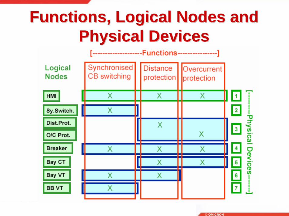
Functions, Logical Nodes and Functions, Logical Nodes and Physical DevicesPhysical Devices

© OMICRON
Data Communication using IEC Data Communication using IEC 6185061850
• Logical Nodes – 92 Logical Node Classes
“IEC61850-7-1 Standard”

© OMICRON
Data Communication using IEC Data Communication using IEC 6185061850
• Logical Groupings – 13 different groups
“IEC61850-7-4 Standard”

© OMICRON
VirtualizationVirtualization

© OMICRON
VirtualizationVirtualization
Real Data/Devicescontroller
(Virtual World)
class
class
class
ACSI Services
Virtual Device
Hid
es/e
ncap
sula
tes
real
Wor
ld
Application

© OMICRON
Data Communication using IEC Data Communication using IEC 6185061850
• Data classes and example
“IEC61850-7-1 Standard”

© OMICRON
Data Communication using IEC Data Communication using IEC 6185061850
• Logical groupings – Devices, nodes, classes and data.
Physical Device (Server)
Logical Device
Logical Node XCBR Logical Node MMXU
Data Class Pos
Data StV
Data Class A
Data PhA

© OMICRON
IEC 61850 Class ModelIEC 61850 Class Model
{Aggregation determined by 7-4 table-references }
{Values and Types are determinedby Common Data Classes}
1..n
XCBR
POS
DATA-ATTRIBUTE
SERVER
LOGICAL-DEVICE
PDISLOGICAL-
NODE
MDD
DATA
**
1..n
* *
Class Model of IEC 61850-7 (Example)
DPCSPS
myXCBR1: XCBR
xyz: LOGICAL-DEVICE
abc: SERVER
pos1: POS
stVal: DATA-ATTRIBUTE
Instances (Examples)
Logical Node Classes defined in 7-4
Data Classes defined in 7-4
Common Data Classes defined in 7-3

© OMICRON
SelfSelf--describing Datadescribing Data
• A client can discover the device server’s capabilities
• Comparable to the services of a web browser
• Used initially when defining the system configuration or during tuning/maintenance of the system

© OMICRON
Modeling Approach Modeling Approach --Standardized extensionsStandardized extensions

© OMICRON
Information Flow Information Flow -- ServicesServices
ISD DataSet, Operate,… <values>
ISD DataReport <values>
ISD DataGet, GetDef,…
<values>
ISD
ISD
Datamulticast <values>

© OMICRON
Communication ConceptsCommunication Concepts

© OMICRON
Basic Reference Model Basic Reference Model --ServicesServices

© OMICRON
Server Building BlocksServer Building BlocksServer
Logical Device nameplate, health
Logical Node
Data
Control
Substitution
Get/Set
Dir/Definition
DataSet
Reporting& Logging Report
Setting GroupActivate
GOOSE GOOSE
SampledValues SMV
Time Synchronisation File TransferAssociation

© OMICRON
Logical Devices as Proxy Logical Devices as Proxy ServersServers
PHD “A“
LD1
LLN0
LD specific
LN
LPHD
PHD specific
LD2
LLN0
LPHDLN
PHD “ B“
LD6
LD5
Proxy/Gateway
LD Proxy
LPHD
LD2
LLN0
LPHDLN
LD1
LLN0
LPHDLN
LLN0
LD5
LD6

© OMICRON
Mapping ExampleMapping Example
XCBR
TCTR
GGIO
TVTR
ATCCTap Changer Controller
Voltage Transformer
Current Transformer
General Input / Output
Circuit Breaker
ICIRC
RFLO
RDRE
PDIS
Disturbance Recorder
Distance Protection
Fault Locator
MMXUMeasurement Unit
XARCMonitoring for Arcs
GAPCAutomatic
Process Control
limitoverflow
added switchcurrent
distance
instantaneous(record)
reactance
RMSdemand
circulatingcurrent
Physical Device Bay ControllerSingle Line Diagram
Example for some currentrelated information

© OMICRON
IEC 61850 Standard IEC 61850 Standard -- System System AspectsAspects
• Part 1 - Introduction and Overview• An introduction and overview of the IEC 61850
standard series. It refers to and includes text and Figures from other parts of the IEC 61850 standard series.
• Part 2 - Glossary• A collection of specific terminology and
definitions used in the context of Substation Automation Systems within the various parts of the standard.
“IEC61850 Standard”

© OMICRON
IEC 61850 Standard IEC 61850 Standard -- System System AspectsAspects
• Part 3 - General Requirements• Quality Requirements ( reliability, maintainability, system
availability, security)• Environmental conditions• Auxiliary Services• Other standards and specifications
• Part 4 - System and Project Management• Engineering (parameter classification, engineering tools,
documentation)• System lifecycle ( product versions, discontinuation, support
after discontinuation)• Quality assurance ( responsibilities, test equipment type
tests, system tests, FAT and SAT)

© OMICRON
IEC 61850 Standard IEC 61850 Standard -- System System AspectsAspects
• Part 5 - Communication Requirements for Functions and Device Models• Logical interfaces• Requirements and interoperability• Substation automation system functions:
• Function categories and list of functions• Specification of functions• Performance requirements of functions
• Logical nodes and PICOMs• Concept• Logical node categories and list of logical nodes• The use of logical nodes, interaction of logical nodes• Specification of message types with performance requirements• List of PICOMs and classification of PICOMs to message types
• Performance calculations for typical substation configurations

© OMICRON
IEC 61850 Standard IEC 61850 Standard --ConfigurationConfiguration
• Part 6 - Substations automation system configuration language• Overview of intended system engineering
process• Definition of system parameter exchange file
format based on XML containing:• primary system schematic (single line) description• Communication connection description• IED capabilities
• Allocation of logical instances to primary system• Allocation of logical nodes to physical devices.

© OMICRON
IEC 61850 Standard IEC 61850 Standard -- Data Data ModellingModelling
• Part 7 Basic Communication Structure for Substation and Feeder Equipment
• Part 7-1 Principles and Models• Introduction to part 7-x• Concepts of communication modeling in IEC 61850
• Part 7-2 Abstract Communication Service Interface• Specification of abstract communication models and
services• Concepts of hierarchical object model

© OMICRON
IEC 61850 Standard IEC 61850 Standard -- Data Data ModellingModelling
• Part 7-3 Common Data Classes
• Part 7-4 Compatible Logical node classes and data classes• Definitions of logical node classes and data
classes• logical node classes are composed of data
classes

© OMICRON
IEC 61850 Standard IEC 61850 Standard -- Station Station Bus MappingBus Mapping
• Part 8-1 - Mapping to MMS and ISO/IEC 8802-3• Mapping of communication models from part 7-2 except the model for
transmission of sampled values

© OMICRON
Mapping to MMSMapping to MMS

© OMICRON
IEC61850 & UCA2 CorrelationIEC61850 & UCA2 Correlation

© OMICRON
IEC 61850 Standard IEC 61850 Standard -- Process Process Bus MappingBus Mapping
• Part 9-1 - Sampled values over serial unidirectional multi-drop point to point link• Mapping of the core elements from the model for
transmission of sampled measured values• Use of IEEE 802.3
• Part 9-2 Sampled values over ISO/IEC 8802-3• Mapping of the complete model for transmission of
sampled measured values and the model for generic object orineted system events (GOOSE)
• The mapping of the other models of part 7-2 is according to part 8-1
“IEC61850 Standard”

© OMICRON
IEC 61850 Standard IEC 61850 Standard -- ScopeScope• Part 9-1 (contd.)

© OMICRON
IEC 61850 Standard IEC 61850 Standard --ConformanceConformance
• Part 10 - Conformance Testing• Conformance test procedure• Quality assurance and testing• Required documentation• Device related conformance testing• Certification of test facilities, requirement and
validation of test equipment

© OMICRON
IEC 61850 Standard IEC 61850 Standard -- SummarySummary
© OMICRON
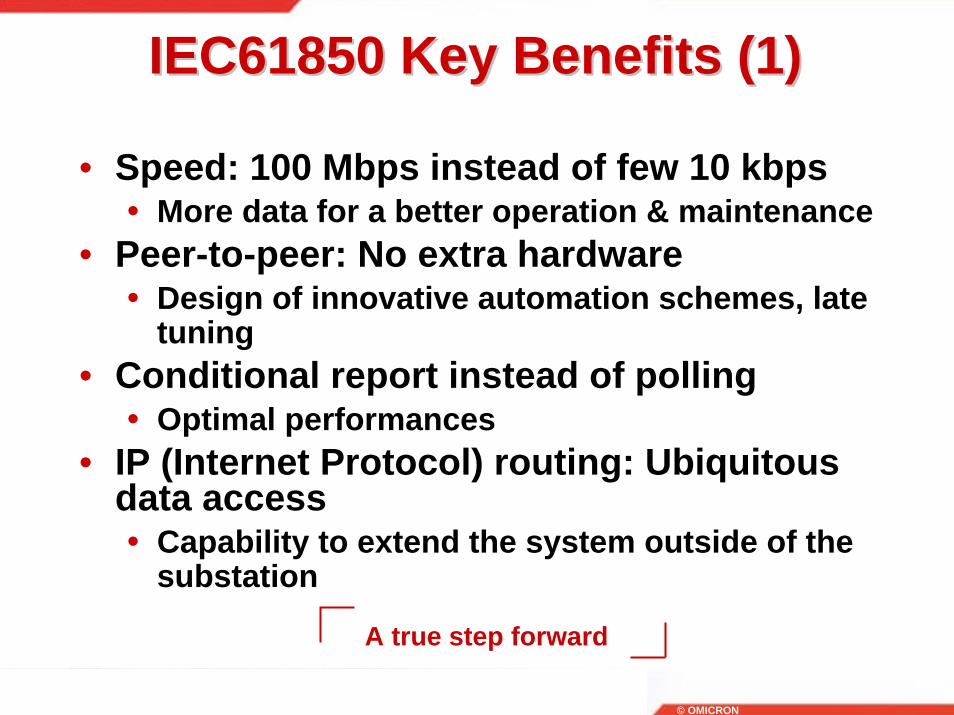
A true step forward
IEC61850 Key Benefits (1)IEC61850 Key Benefits (1)
• Speed: 100 Mbps instead of few 10 kbps• More data for a better operation & maintenance
• Peer-to-peer: No extra hardware• Design of innovative automation schemes, late
tuning• Conditional report instead of polling
• Optimal performances• IP (Internet Protocol) routing: Ubiquitous
data access• Capability to extend the system outside of the
substation

© OMICRON
IEC61850 Key Benefits (2)IEC61850 Key Benefits (2)
• Client-server: Instead of master-slave• Flexible designs easy to upgrade
• Pre-defined names: Single vocabulary between users• Easier engineering between teams
• XML references: Formal interfaces• Consistency between engineering tools
• IEC 61850 is independent of short term benefits: focuses on the “long living application objects”

© OMICRON
IEC61850 Key Benefits (3)IEC61850 Key Benefits (3)
• Independent of current product; stable over several product cycles (long term stability)
• Independent of operating systems and programming languages
• independent of middleware• Independent of communication systems• Independent of vendor (multi-vendor
support)