talos on-line help manual -- alignments · talos on-line help manual ... (cm20/cm200 feg,...
TRANSCRIPT

Talos 12 on-line help Alignments Version 1.6 and higher
1
Talos on-line help manual -- Alignments Table of Contents 1 Alignments ........................................................................................................................................... 4
1.1 Introduction .................................................................................................................................. 4 1.2 Alignment procedures .................................................................................................................. 5
1.2.1 Basic alignment procedures overview ...................................................................................... 6 1.2.2 Application alignment procedures overview ............................................................................. 7
2 Introduction to electron optics ............................................................................................................. 9 2.1 Electron gun ................................................................................................................................. 9
2.1.1 Field Emission Gun .................................................................................................................. 9 2.2 Electron optics elements ............................................................................................................ 10
2.2.1 Lenses .................................................................................................................................... 10 2.3 Deflection coils ........................................................................................................................... 11
2.3.1 Pivot points ............................................................................................................................. 12 2.3.2 Gun coils ................................................................................................................................. 14 2.3.3 Beam coils .............................................................................................................................. 14 2.3.4 Image coils ............................................................................................................................. 15
2.4 Stigmators .................................................................................................................................. 15 2.5 Focusing the diffraction pattern .................................................................................................. 16 2.6 The diffraction shadow image .................................................................................................... 17
3 Gun .................................................................................................................................................... 19 3.1 Gun Tilt ....................................................................................................................................... 19 3.2 Gun Tilt Pivot Point .................................................................................................................... 19 3.3 Gun Shift .................................................................................................................................... 19 3.4 Spot size-dependent Gun Shift .................................................................................................. 20
4 Align NanoProbe ............................................................................................................................... 21 4.1 Basic SA ..................................................................................................................................... 21 4.2 Basic Mh .................................................................................................................................... 21 4.3 Basic Ml ...................................................................................................................................... 22 4.4 Focus & Stigmate Beam nP ....................................................................................................... 22
5 Align HM-TEM ................................................................................................................................... 24 5.1 Basic SA ..................................................................................................................................... 24 5.2 All SA magnifications ................................................................................................................. 24 5.3 Basic Mh .................................................................................................................................... 25 5.4 Basic Ml ...................................................................................................................................... 26 5.5 All Mh magnifications ................................................................................................................. 26 5.6 All Ml magnifications .................................................................................................................. 26 5.7 All camera lengths ...................................................................................................................... 27 5.8 All SA magnifications - fine ........................................................................................................ 27 5.9 All Mh magnifications - fine ........................................................................................................ 27 5.10 All Ml magnifications - fine ......................................................................................................... 28 5.11 Focus & Stigmate Beam uP ....................................................................................................... 28
6 Align LM ............................................................................................................................................ 30 6.1 Basic LM .................................................................................................................................... 30 6.2 All LM magnifications ................................................................................................................. 30 6.3 All LAD camera lengths .............................................................................................................. 31 6.4 All LM magnifications - fine ........................................................................................................ 31 6.5 Focus & Stigmate Beam LM ...................................................................................................... 32
Talos 12 on-line help Alignments Version 1.6 and higher
2
7 Stigmators ......................................................................................................................................... 34 7.1 Condenser (uP) / Condenser (nP) ............................................................................................. 34 7.2 Objective .................................................................................................................................... 34 7.3 Diffraction ................................................................................................................................... 35 7.4 Condenser 3 fold ........................................................................................................................ 35
8 Calibrate NanoProbe ......................................................................................................................... 36 8.1 Calibrate Trackball ..................................................................................................................... 36 8.2 Calibrate Beam Shift .................................................................................................................. 36 8.3 Calibrate Beam Tilt ..................................................................................................................... 37 8.4 Image/Beam calibration ............................................................................................................. 37
9 Calibrate HM-TEM ............................................................................................................................. 39 9.1 Calibrate Trackball ..................................................................................................................... 39 9.2 Calibrate Shifts ........................................................................................................................... 39 9.3 Calibrate Tilts ............................................................................................................................. 40 9.4 Image/Beam calibration ............................................................................................................. 40
10 Calibrate LM .................................................................................................................................. 42 10.1 Calibrate Trackball ..................................................................................................................... 42 10.2 Calibrate Shifts ........................................................................................................................... 42 10.3 Calibrate Tilts ............................................................................................................................. 43 10.4 Image/beam calibration .............................................................................................................. 43
11 Dyn. Conical DF Microprobe .......................................................................................................... 45 11.1 Pivot point .................................................................................................................................. 45 11.2 Distortion .................................................................................................................................... 45 11.3 Calibrate Tilt ............................................................................................................................... 45
12 Dyn. Conical DF NanoProbe ......................................................................................................... 46 12.1 Pivot point .................................................................................................................................. 46 12.2 Distortion .................................................................................................................................... 46 12.3 Calibrate Tilt ............................................................................................................................... 47
13 HM-STEM ...................................................................................................................................... 48 13.1 Preparation ................................................................................................................................. 48 13.2 Intensity preset ........................................................................................................................... 48 13.3 PP_BT ........................................................................................................................................ 48 13.4 Rotation center ........................................................................................................................... 49 13.5 Scan Pivot Point ......................................................................................................................... 49 13.6 Scan distortion adjustment ......................................................................................................... 49 13.7 Scan default rotation .................................................................................................................. 50
14 STEM MicroProbe ......................................................................................................................... 52 14.1 Preparation ................................................................................................................................. 52 14.2 Intensity preset ........................................................................................................................... 52 14.3 PP_BT ........................................................................................................................................ 52 14.4 Rotation center ........................................................................................................................... 53 14.5 Scan Pivot Point ......................................................................................................................... 53 14.6 Scan distortion adjustment ......................................................................................................... 53 14.7 Scan default rotation .................................................................................................................. 54
15 LM-STEM ....................................................................................................................................... 56 15.1 Preparation ................................................................................................................................. 56 15.2 Intensity preset ........................................................................................................................... 56 15.3 Scan Pivot Point ......................................................................................................................... 56 15.4 Align Diffraction Pattern ............................................................................................................. 56 15.5 Scan distortion adjustment ......................................................................................................... 57 15.6 Scan default rotation .................................................................................................................. 58
16 Phase plate .................................................................................................................................... 59 16.1 Phase plate alignment with the halo method.............................................................................. 59

Talos 12 on-line help Alignments Version 1.6 and higher
3
16.2 Phase plate alignment with the Ronchigram method ................................................................. 61

Talos 12 on-line help Alignments Version 1.6 and higher
4
1 Alignments
1.1 Introduction The alignment strategy is based on the following:
• Perform Talos full alignment only once. • Users only perform and store “daily use alignments”.
This strategy has been implemented as follows: • The Supervisor is the alignment manager:
The Supervisor is one person on-site who is responsible for the microscope. He or she takes care of the complete alignment of the microscope. The Supervisor (and Service or Factory) is therefore the only one that can go through the complete alignment and store alignment files. Note that alignment files do not any longer contain settings applicable to more than one high tension setting. Each alignment file is thus specific to one high tension. There should be only one alignment file per high tension setting, named appropriately so it is clear to users what each alignment file means. At most a microscope therefore should have a maximum of six alignment files. Normal microscope users (including experts) can only perform a limited alignment procedure plus a number of direct alignments. The results of these alignments are stored (per user) in the registry. Normal microscope users cannot store alignments in standard alignment files. Instead the user can store the alignments done, together with all other relevant settings in FEG Registers.
• Alignment structure: Alignment procedures are split into basic alignments and applications alignments. The basic alignments are essential and should always be executed in full, following a top-down approach. An applications alignment concerns a particular application (like STEM or EFTEM) and they can be done in any order provided that the basic alignments have been done.
Procedures are split into basic and applications alignments.

Talos 12 on-line help Alignments Version 1.6 and higher
5
• Fast and consistent alignments: Within one procedure, a unique optical setting is chosen and all relevant parameters are aligned. Performing all these alignments in one procedure ensures that the right sequence is followed and minimized the preparation effort.
• Removal of non-essential optical controls: Where possible, controls that can lead to misalignment, are disabled. For example, there are a number of alignment steps where the focus should not be changed (the correct focus has been set already in a previous step). If that is the case, the Focus knob on the control pad will be disconnected and not do anything.
The benefits are: • Stable alignment for all users. • Better and faster alignment procedures for the alignment manager. • Easy way of going back to a good alignment : simply load the file with the correct alignment for the
current high tension setting.
1.2 Alignment procedures Below is a list of alignment procedures. Some of the procedure steps may not be visible (dependent on user level 'user' or 'expert'). Some alignments like STEM may also be absent, since they depend on the hardware configuration of the instrument. General notes: 1. Alignment procedures are split into basic alignments and applications alignments. The basic
alignments are essential and should always be executed in full, following a top-down approach. An applications alignment concern a particular application (like STEM) and they can be done in any order provided that the basic alignments are done.
2. In some application alignment procedures, some steps may be skipped when using Next and Previous. This is done to skip those alignments that are not sensitive to changes in operating conditions (like pivot points), so that the procedure only follows the more often-used alignments. The visual indication which alignments are skipped and which are executed, takes the form of two different icons in front of the subprocedure step. Where the icon is a blue arrow on a white background, pointing to the right (into the subprocedure) the subprocedure is not skipped. Where the arrow points down on a yellow background, the subprocedure is skipped.

Talos 12 on-line help Alignments Version 1.6 and higher
6
1.2.1 Basic alignment procedures overview Gun • Gun Tilt • Gun Tilt Pivot Point • Gun Shift • Spot size-dependent Gun Shift Align NanoProbe • Basic SA • Basic Mh • Basic Ml • Focus & Stigmate Beam nP Align HM-TEM • Basic SA • All SA magnifications • Basic Mh • Basic Ml • All Mh magnifications • All Ml magnifications • All camera lengths • All SA magnifications - fine • All Mh magnifications - fine • All Ml magnifications - fine • Focus & Stigmate Beam uP Align LM • Basic LM • All LM magnifications • All LAD camera lengths • All LM magnifications - fine • Focus & Stigmate Beam LM Align Lorentz • Basic SA • All SA magnifications • Basic Mh • Basic Ml • All Mh magnifications • All Ml magnifications • All camera lengths • All SA magnifications - fine • All Mh magnifications - fine • All Ml magnifications - fine • Focus & Stigmate Beam uP

Talos 12 on-line help Alignments Version 1.6 and higher
7
Stigmators • Condenser (uP) • Condenser (nP) • Objective • Diffraction • Condenser 3 fold
1.2.2 Application alignment procedures overview Calibrate NanoProbe • Calibrate Trackball • Calibrate Beam Shift • Calibrate Beam Tilt • Image/Beam calibration Calibrate HM-TEM • Calibrate Trackball • Calibrate Shifts • Calibrate Tilts • Image/Beam calibration Calibrate LM • Calibrate Trackball • Calibrate Shifts • Calibrate Tilts • Image/beam calibration Dyn. Conical DF Microprobe • Pivot point • Distortion • Calibrate Tilt Dyn. Conical DF NanoProbe • Pivot point • Distortion • Calibrate Tilt HM-STEM • Preparation • Intensity preset • PP_BT & Rotation Center • Scan Pivot Point • Scan distortion adjustment • Scan default rotation STEM MicroProbe • Preparation • Intensity preset • PP_BT & Rotation Center

Talos 12 on-line help Alignments Version 1.6 and higher
8
• Scan Pivot Point • Scan distortion adjustment • Scan default rotation LM-STEM • Preparation • Intensity preset • Scan Pivot Point • Align Diffraction Pattern • Scan distortion adjustment • Scan default rotation
Talos 12 on-line help Alignments Version 1.6 and higher
9
2 Introduction to electron optics The microscope consists essentially of three parts: 1. The electron gun where the beam is generated. 2. The lenses, deflection coils and stigmators that make the image and project it on the screen. 3. The projection chamber with one or more types of electron detectors to record images, diffraction
patterns, ... (plate camera, TV, ...). The first two topics will be covered in this section.
2.1 Electron gun The electron beam is generated in the electron gun. Two basic types of gun can be distinguished: the thermionic gun and the field emission gun (FEG). • Thermionic guns are based on two types of filaments: tungsten (W) and lanthanum-hexaboride
(LaB6). On modern instruments the different types of thermionic filaments can be used interchangeably.
• The FEG employs either a (thermally-assisted) cold field emitter - as on the Philips EM 400-FEG - or a Schottky emitter - as on the more recent generations of FEG microscopes (CM20/CM200 FEG, CM30/CM300 FEG, Tecnai F20 and F30, Titan).
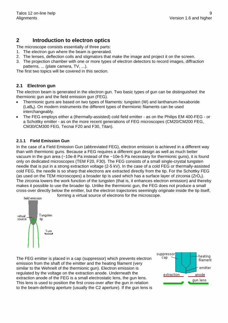
2.1.1 Field Emission Gun In the case of a Field Emission Gun (abbreviated FEG), electron emission is achieved in a different way than with thermionic guns. Because a FEG requires a different gun design as well as much better vacuum in the gun area (~10e-8 Pa instead of the ~10e-5 Pa necessary for thermionic guns), it is found only on dedicated microscopes (TEM F20, F30). The FEG consists of a small single-crystal tungsten needle that is put in a strong extraction voltage (2-5 kV). In the case of a cold FEG or thermally-assisted cold FEG, the needle is so sharp that electrons are extracted directly from the tip. For the Schottky FEG (as used on the TEM microscopes) a broader tip is used which has a surface layer of zirconia (ZrO2). The zirconia lowers the work function of the tungsten (that is, it enhances electron emission) and thereby makes it possible to use the broader tip. Unlike the thermionic gun, the FEG does not produce a small cross-over directly below the emitter, but the electron trajectories seemingly originate inside the tip itself,
forming a virtual source of electrons for the microscope.
The FEG emitter is placed in a cap (suppressor) which prevents electron emission from the shaft of the emitter and the heating filament (very similar to the Wehnelt of the thermionic gun). Electron emission is regulated by the voltage on the extraction anode. Underneath the extraction anode of the FEG is a small electrostatic lens, the gun lens. This lens is used to position the first cross-over after the gun in relation to the beam-defining aperture (usually the C2 aperture). If the gun lens is
Talos 12 on-line help Alignments Version 1.6 and higher
10
strong, the cross-over lies high above the aperture while a weak gun lens positions the cross-over close to the aperture, giving a high current but at the expense of aberrations on the beam. A strong gun lens is therefore used where small, intense and low-aberration electron probes are needed (diffraction, analysis and scanning), while a weak gun lens is used when high currents are important (TEM imaging). In the latter case, the beam is spread and the aberrations do not affect the area within the field of view. The high brightness of FEGs comes about because of two reasons: 1. The small size of the tip ensures that large numbers of electrons are emitted from a small area (high
A/cm²). 2. The electrons come out of the tungsten crystal with a very restricted range of emission angles (high
A/srad). FEGs also have a low energy spread due to their low working temperature and emission geometry (small virtual source size, but much larger actual size of the emitting area).
2.2 Electron optics elements Electron optics elements in the microscope column fall into three different categories: lenses, deflection coils and stigmators. 1. Lenses are the most important. They provide us with the means to (de)focus the electron beam on
the specimen (the condenser system), focus the image (the objective lens), change the magnification and switch between image and diffraction (the magnification system).
2. Deflection coils allow us to shift or tilt the beam. In most cases this is used to correct for mechanical misalignments of the column. There are also other cases where the deflection coils are used to obtain a specific effect, such as tilting the beam in dark field or shifting the beam in STEM.
3. Stigmators are elements that allow us to correct for deficiencies in the electron lenses. In principle lenses are round and perfectly symmetrical. In practice there are small deviations from perfection which are corrected with the stigmators.
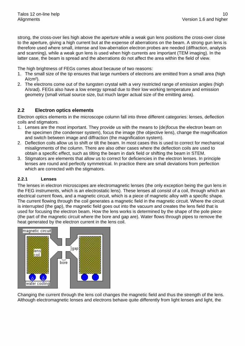
2.2.1 Lenses The lenses in electron microscopes are electromagnetic lenses (the only exception being the gun lens in the FEG instruments, which is an electrostatic lens). These lenses all consist of a coil, through which an electrical current flows, and a magnetic circuit, which is a piece of magnetic alloy with a specific shape. The current flowing through the coil generates a magnetic field in the magnetic circuit. Where the circuit is interrupted (the gap), the magnetic field goes out into the vacuum and creates the lens field that is used for focusing the electron beam. How the lens works is determined by the shape of the pole piece (the part of the magnetic circuit where the bore and gap are). Water flows through pipes to remove the heat generated by the electron current in the lens coil.
Changing the current through the lens coil changes the magnetic field and thus the strength of the lens. Although electromagnetic lenses and electrons behave quite differently from light lenses and light, the

Talos 12 on-line help Alignments Version 1.6 and higher
11
general principles of light optics can be applied and the electromagnetic lenses can be described for convenience like the lenses of light optics. The Titan has three condenser lenses: • The first condenser lens, or C1, determines the demagnification (size reduction) of the electron
source onto the specimen and thus the spot size. Its control is found under the spot size control, which has 11 steps.
• The second condenser lens (C2) and third condenser lens (C3) are generally used in combination and determine how strongly the beam is focused onto the specimen and the convergence angle of the beam. As a consequence it varies the intensity of the beam on the viewing screen. The C2 lens is controlled through the Intensity knob. Close to the second condenser lens there is an aperture (the second-condenser or C2 aperture), which is used as the beam-defining aperture (it limits the amount of the beam convergence for a fully focused beam).
The magnification system of the microscope consists of a set of five lenses: the objective, diffraction, intermediate, projector 1 and projector 2 lenses. Except in low-magnification (LM) mode, the objective lens is always the strongest lens in the microscope, magnifying between about 20 and 50x, depending on the type of objective lens. The individual lenses of the magnification (or projector) system are not controlled directly by the operator, but instead the microscope contains a number of magnifications for image and diffraction mode, each with its own settings of the magnifying lenses. The only lenses that are controlled directly by the operator are the objective lens (for focusing the image) and the diffraction lens (for focusing the diffraction pattern). In LM mode the objective lens is switched (nearly) off in order to achieve the smallest magnifications. With the objective lens off, the diffraction lens is used for focusing the image. The electron-optical configuration in LM is reversed with respect to the high-magnification range: the functions of the objective and diffraction lenses and stigmators switch as do the functions of the objective and selected-area apertures. Lens and aperture functions in HM (objective lens on) and LM (objective lens off) High Magn Low Magn Obj. lens Image focus Diffraction (LAD) focus Diff. lens Diffraction focus Image focus Obj. aperture Contrast forming Area selection SA aperture Area selection Contrast forming Obj. stigmator Image stigmation Diffraction stigmation Diff. stigmator Diffraction stigmation Image stigmation TWIN-type objective lenses The Titan microscopes are equipped with a TWIN-type objective lens. The lens design and the two resulting basic optical modes, the microprobe and nanoprobe modes, are discussed separately in more detail.
2.3 Deflection coils Throughout the microscope, the path followed by the electron beam is affected by a number of deflection coils, mounted in different locations. Deflection coils play an essential role in the alignment of the microscope and are used for aligning the gun, beam, objective lens, magnification system (image and diffraction shifts to the screen center) and detector alignments (image or diffraction shifts to a detector

Talos 12 on-line help Alignments Version 1.6 and higher
12
that is situated off the optical axis). Most of the steps in the alignment procedures either align the deflection coils themselves or use the deflection coils to align another electron-optical element. In principle a single deflection coil is sufficient for a particular action, provided that it is mounted at the level where its action is needed. In practice, such arrangements are not feasible due to space limitations or other constraints. All deflections are done therefore through double deflection coils that are situated at another level in the microscope. A deflection coil is a set of coils on either side of the electron beam. If one is given a positive magnetic field and the other one a negative one, the electrons in the beam will be attracted by the positive field and repelled by the other, leading to a deflection towards the positive coil. The actual coils are extended over arcs of 120°. The arcs are used to generate a homogeneous magnetic field. By arranging the coils in sets of two, mounted perpendicular to each other (X and Y directions), the beam can be deflected into any direction by a suitable combination of x and y. The deflection coils are always mounted in sets of two above another (so-called double deflection coils). Use of double deflection coils involves the important concept of pivot points as explained below. Each microscope has four sets of double deflection coils: the gun coils just underneath the high-tension accelerator; the condenser coils (only used for alignment; located between the C2 and C3 lenses); the beam deflection coils above the objective lens; and the image deflection coils below the objective lens. The beam and image coils have separate DC (static shifts) and AC (scanning) coils. Two additional, one-directional coils form the microscope beam blanker (at the level of the gun deflection coils) and the shutter (in the projector system) that are used for plate negatives and CCD exposures.
2.3.1 Pivot points Double deflection coils are capable of two completely independent actions, a tilt and a shift. These two actions should be decoupled, that is, when a shift is intended only a shift and no tilt should occur (a pure shift) and vice versa (pure tilt). Examples of the importance of pure shift are: • high-resolution imaging, where a beam tilt would undo all the effort spent in correctly aligning the
objective lens; • scanning, where a tilt in addition to the beam shift will change the magnification; • TEM dark-field imaging, where a beam shift with an additional beam tilt would change the incident-
beam direction and thus the nature of the diffracting condition. Because of the importance of pure shift and pure tilt, considerable effort is spent in correctly aligning the deflection coils. No two electron microscope columns are exactly identical and slight differences that

Talos 12 on-line help Alignments Version 1.6 and higher
13
exist between deflection coils make it necessary to align the coils by means of setting pivot points. A pivot point is simply a point around which the beam will pivot (like the analogue of the seesaw in the children's' playground). The alignment of the pivot point determines the relation between the two coils used, making sure that the beam pivots around the correct point.
The concept of the pivot point is probably easiest to understand for beam deflection coils in a simplified microscope consisting of a double deflection coil followed by a lens with equal distances between the deflection coils and between the lower coil and the image plane above the lens. A beam shift comes about by deflecting the beam through an angle a by the upper coil and then doing the reverse (-a) with the lower coil. In a perfect system the beam would come out parallel to its initial direction but displaced sideways. Since all beams that are parallel at the image plane must go through a single point in the back-focal plane, shifting the beam should have no effect on the location of the beam in the back-focal plane. A beam tilt comes about by deflecting the beam through an angle a with the upper deflection coil and then deflecting by -2a by the lower coil. A beam tilt will result in a beam shift in the back-focal plane but should cause no shift in the image plane.
If a combination of beam shift and beam tilt is needed, then the settings for these are simply added. In the example above, setting beam tilt plus beam shift would involve setting an angle 2a on the upper coils and -3a on the lower coil. Setting the pivot points is done by deflecting the beam with a wobbler and minimising any movement - of the beam in the diffraction plane in the case of beam shift (no tilt should occur) and of the beam in the image in the case of beam tilt (no shift should occur). A wobbler is a mechanism for rapidly switching a
Talos 12 on-line help Alignments Version 1.6 and higher
14
microscope element or function from a negative value to an identical but positive value; it can thus be on beam shift or beam tilt, image shift, a stigmator, objective-lens current, high tension, etc., even though the traditional meaning is the beam-tilt aid for focusing the TEM image. Since a beam tilt is visible in diffraction as a diffraction shift, beam shift pivot points are set in diffraction mode, while beam tilt pivot points are set in image mode - where a beam shift will be visible. Where it is important, pivot point alignment has two adjustable directions - a main one and the perpendicular correction. If the coils were perfect, the latter would not be necessary. In practice a small correction may be needed, because the lower coils is rotated slightly relative to the upper one. If the perpendicular correction is unnecessary (e.g. for the gun tilt pivot points), then only the main direction is adjustable (only the Multifunction X knob works).
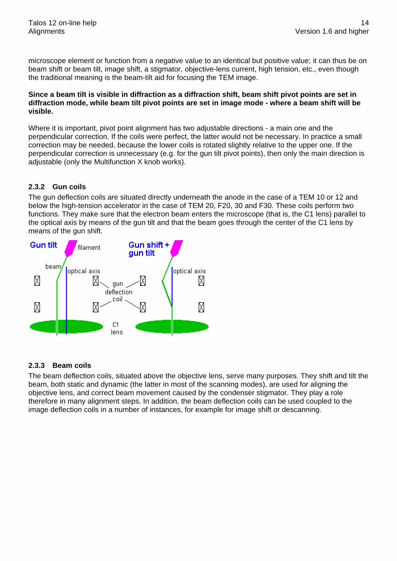
2.3.2 Gun coils The gun deflection coils are situated directly underneath the anode in the case of a TEM 10 or 12 and below the high-tension accelerator in the case of TEM 20, F20, 30 and F30. These coils perform two functions. They make sure that the electron beam enters the microscope (that is, the C1 lens) parallel to the optical axis by means of the gun tilt and that the beam goes through the center of the C1 lens by means of the gun shift.
2.3.3 Beam coils The beam deflection coils, situated above the objective lens, serve many purposes. They shift and tilt the beam, both static and dynamic (the latter in most of the scanning modes), are used for aligning the objective lens, and correct beam movement caused by the condenser stigmator. They play a role therefore in many alignment steps. In addition, the beam deflection coils can be used coupled to the image deflection coils in a number of instances, for example for image shift or descanning.

Talos 12 on-line help Alignments Version 1.6 and higher
15
2.3.4 Image coils The image deflection coils, situated below the objective lens, have many uses. They shift the image and the diffraction pattern, to align various magnifications, camera lengths and modes (such as TEM and STEM), they correct image or diffraction-pattern movement caused by the objective and diffraction stigmators, respectively, and set the Detector alignments that move the image or diffraction pattern to a detector that is situated off the microscope axis (STEM BF/DF, TV). In addition, the image deflection coils can be used coupled to the beam deflection coils in a number of instances, for example for image shift or descanning.
2.4 Stigmators Even though considerable effort is spent in order to ensure high lens quality, none of the lenses in a microscope is 100 percent perfect. Small inhomogeneities remain or can come about later, for instance by dust adhering to a pole piece or by magnetism or charging of the specimen itself. These imperfections cause a loss of rotational symmetry of the lens. In one direction the lens will therefore focus more strongly than in the perpendicular direction, causing an asymmetry called astigmatism. This image defect is corrected by the stigmator. The stigmator consists of a quadrupole, which basically is a lens whose astigmatism can be varied continuously. The quadrupole has four elements, arranged at 90 degrees around the beam. These elements are used together in two sets, with each set lying on opposite sides of the beam. If one set is given a positive value and the other a negative, then the positive elements will attract the electrons and have a defocusing effect, while the negative elements repel the electrons and focus (green arrows). The resulting astigmatism (dark red ellipse) cancels the astigmatism in the electron lens (making the beam round: red circle). The actual design of the stigmators inside the microscope is - as with the deflection coils - more complicated and based on a magnetic field (field direction and strength shown by blue arrows). Each stigmator consists of two of the elements, one mounted above the other and rotated by 45° with respect to each other. Each of these elements is controlled by one of the Multifunction knobs (X and Y directions). The combination of two elements allows correction of the astigmatism in any direction.
Microscopes have three sets of stigmators: the condenser stigmator to make the focused beam circular; the objective stigmator to correct astigmatism in the high-magnification (M, SA) image and the low-angle diffraction (LAD) pattern; and the diffraction stigmator to correct astigmatism in the diffraction pattern and the low-magnification (LM) image. The quadrupoles used as stigmator can only correct second-order astigmatism. Fortunately (or perhaps logically), this is the strongest astigmatism found. Third-order astigmatism is usually apparent only in the so-called caustic image. This type of image is obtained when a strongly convergent beam is focused into
Talos 12 on-line help Alignments Version 1.6 and higher
16
a small spot, as can be the case for a diffraction pattern or nanoprobe. Occasionally, fourth-order astigmatism is observed when small, dirty objective apertures are used. Because the stigmator settings vary from one mode to another and between various spot sizes, a number of independent stigmator values are stored by the microscope.
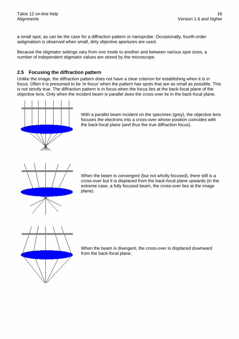
2.5 Focusing the diffraction pattern Unlike the image, the diffraction pattern does not have a clear criterion for establishing when it is in focus. Often it is presumed to be 'in focus' when the pattern has spots that are as small as possible. This is not strictly true. The diffraction pattern is in focus when the focus lies at the back-focal plane of the objective lens. Only when the incident beam is parallel does the cross-over lie in the back-focal plane.
With a parallel beam incident on the specimen (grey), the objective lens focuses the electrons into a cross-over whose position coincides with the back-focal plane (and thus the true diffraction focus). When the beam is convergent (but not wholly focused), there still is a cross-over but it is displaced from the back-focal plane upwards (in the extreme case, a fully focused beam, the cross-over lies at the image plane). When the beam is divergent, the cross-over is displaced downward from the back-focal plane.
Talos 12 on-line help Alignments Version 1.6 and higher
17
If the diffraction pattern is not focused properly, there are a number of consequences: • The camera length can be wrong • The diffraction will be rotated away from its proper orientation • The pattern may be distorted • Alignments such as beam shift pivot points can be wrong • The scanning magnification can be wrong due to misaligned pivot points Due to the absence of a clear criterion, we end up with a chicken-and-egg situation (what was first, the chicken or the egg?). For example, if it can be assumed that the shift pivot points are correct, then it is easy to establish the correct diffraction focus by wobbling a beam shift and minimising diffraction-pattern movement. However, the pivot points can only be aligned correctly if the diffraction pattern is focused properly. In order to resolve this situation, on the Titan the diffraction focus is established by focusing on the edge of the objective aperture. After the alignments have been done (camera lengths), the diffraction focus can also be found by simply pressing the Eucentric focus button (this resets the variable diffraction focus to zero). With this method for establishing diffraction focus, the SA aperture is not (and should not be) used.
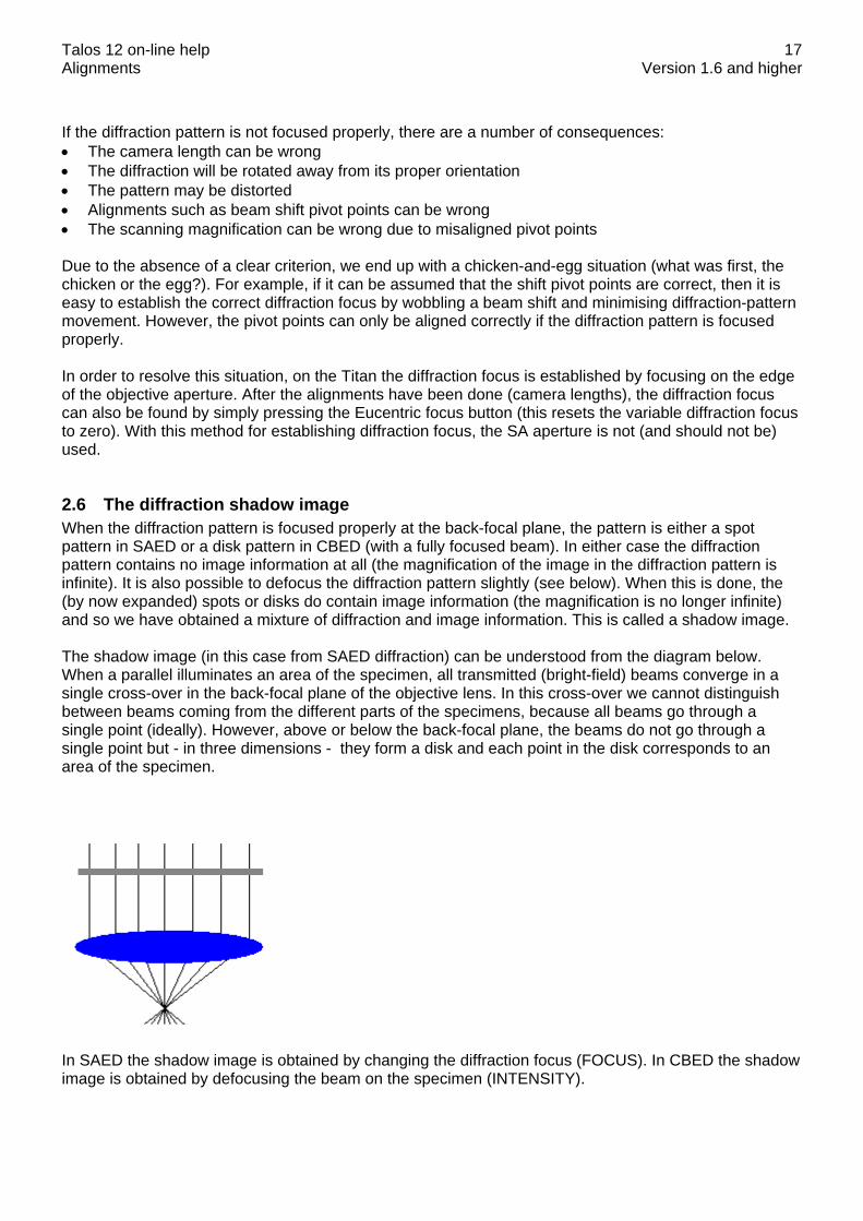
2.6 The diffraction shadow image When the diffraction pattern is focused properly at the back-focal plane, the pattern is either a spot pattern in SAED or a disk pattern in CBED (with a fully focused beam). In either case the diffraction pattern contains no image information at all (the magnification of the image in the diffraction pattern is infinite). It is also possible to defocus the diffraction pattern slightly (see below). When this is done, the (by now expanded) spots or disks do contain image information (the magnification is no longer infinite) and so we have obtained a mixture of diffraction and image information. This is called a shadow image. The shadow image (in this case from SAED diffraction) can be understood from the diagram below. When a parallel illuminates an area of the specimen, all transmitted (bright-field) beams converge in a single cross-over in the back-focal plane of the objective lens. In this cross-over we cannot distinguish between beams coming from the different parts of the specimens, because all beams go through a single point (ideally). However, above or below the back-focal plane, the beams do not go through a single point but - in three dimensions - they form a disk and each point in the disk corresponds to an area of the specimen.
In SAED the shadow image is obtained by changing the diffraction focus (FOCUS). In CBED the shadow image is obtained by defocusing the beam on the specimen (INTENSITY).

Talos 12 on-line help Alignments Version 1.6 and higher
18
The shadow image is often used when working with crystals: • During tilting it allows observation of both crystal orientation (from the diffraction pattern) and position
(the shadow image), making it easier to correct (with X-Y stage movement) for apparent image shift during tilting (especially with the non-eucentric b tilt).
• It can be used to create multiple dark-field images (the pattern contains the bright-field disk with the bright-field image and several diffraction disks, each with its own dark-field image).
• It can be used to position, focus and stigmate the focused beam accurately while in diffraction (or STEM).
In the shadow image, there are a couple of effects dependent on the direction of defocusing (under- or overfocus). In going from under- to overfocus the shadow image: • Flips by 180°. • Inverts the contrast. Because of these effects, one should work consistently (either always underfocus or always overfocus).
Talos 12 on-line help Alignments Version 1.6 and higher
19
3 Gun
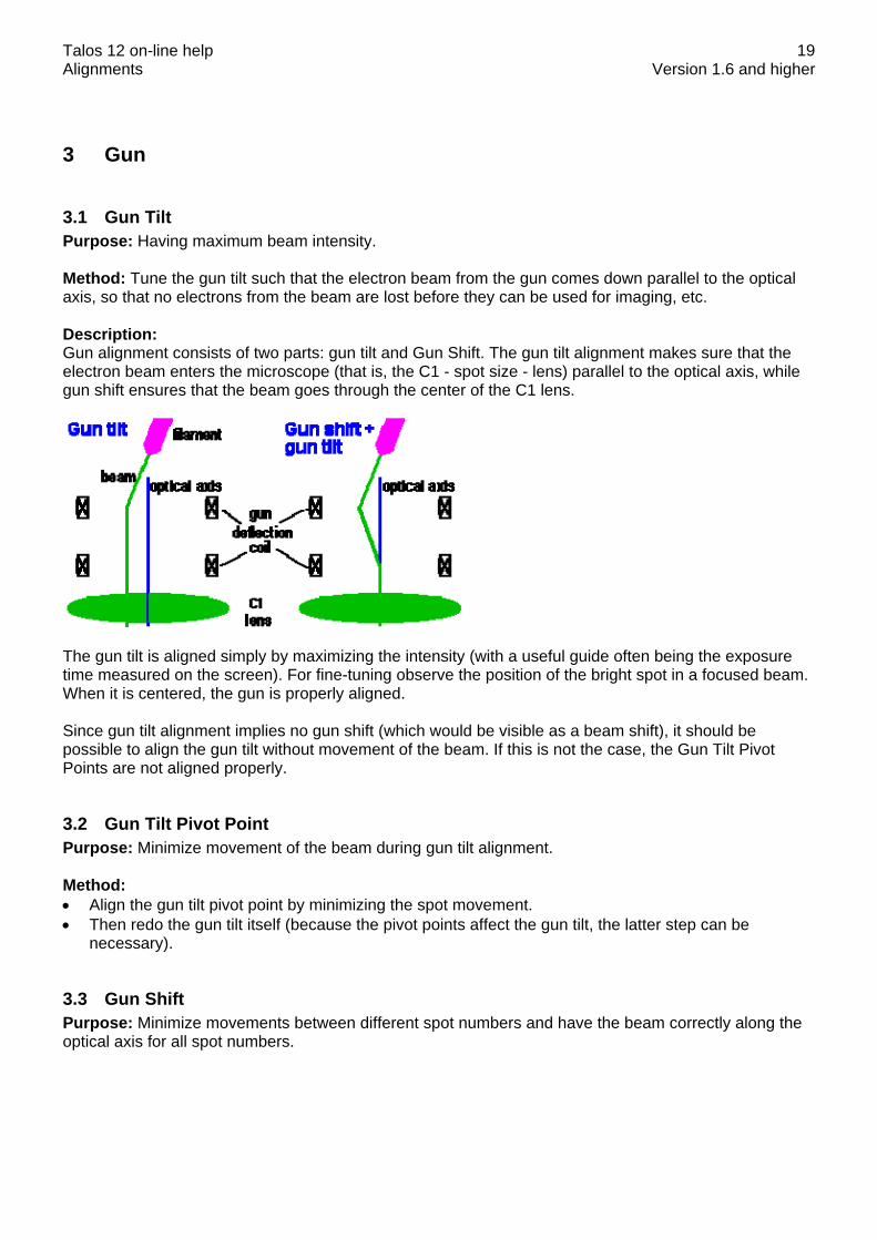
3.1 Gun Tilt Purpose: Having maximum beam intensity. Method: Tune the gun tilt such that the electron beam from the gun comes down parallel to the optical axis, so that no electrons from the beam are lost before they can be used for imaging, etc. Description: Gun alignment consists of two parts: gun tilt and Gun Shift. The gun tilt alignment makes sure that the electron beam enters the microscope (that is, the C1 - spot size - lens) parallel to the optical axis, while gun shift ensures that the beam goes through the center of the C1 lens.
The gun tilt is aligned simply by maximizing the intensity (with a useful guide often being the exposure time measured on the screen). For fine-tuning observe the position of the bright spot in a focused beam. When it is centered, the gun is properly aligned. Since gun tilt alignment implies no gun shift (which would be visible as a beam shift), it should be possible to align the gun tilt without movement of the beam. If this is not the case, the Gun Tilt Pivot Points are not aligned properly.
3.2 Gun Tilt Pivot Point Purpose: Minimize movement of the beam during gun tilt alignment. Method: • Align the gun tilt pivot point by minimizing the spot movement. • Then redo the gun tilt itself (because the pivot points affect the gun tilt, the latter step can be
necessary).
3.3 Gun Shift Purpose: Minimize movements between different spot numbers and have the beam correctly along the optical axis for all spot numbers.

Talos 12 on-line help Alignments Version 1.6 and higher
20
Method: • Center spot 9 with the beam deflection coils. • Center spot 3 with the gun deflection coils. • Repeat the two steps until the change in gun shift is very small. Note: In the gun shift procedure the spot-size dependent gun shift values for spots 3 and 9 are reset to zero (for proper alignment the spot-size dependent gun shift should therefore be done after the gun shift procedure). Description: Gun alignment consists of two parts: Gun Tilt and gun shift. The gun tilt alignment makes sure that the electron beam enters the microscope (that is, the C1 - spot size - lens) parallel to the optical axis, while gun shift ensures that the beam goes through the center of the C1 lens.
When spot size 9 is used (or any spot size above that), the C1 lens is strong. Under these conditions all aberrations of the microscope system above it are demagnified by the lens (C1 works in the opposite way of the magnification system; instead of magnifying the image, it makes the image of the source - the electron gun - smaller). Thus the demagnification of the misalignment of the gun shift is much smaller for spot 9 than for spot 3, so spot 9 gives the reference ('no' gun shift) and spot 3 defines the gun shift itself. The remaining deviations are corrected by the Spot-size dependent Gun Shift.
3.4 Spot size-dependent Gun Shift Purpose: Minimize movements between different spot numbers and have the beam correctly along the optical axis for all spot numbers. Method: Set the exact Gun Shift by aligning all spots relative to spot 9. • Center spot 5 with the beam deflection coils. • Center spot 9 is centered with the beam deflection coils (spot 5 is done first because spot 9 may be
difficult to find, especially if the beam is defocused). • Center all spots (setting the spot-dependent gun shift).
Talos 12 on-line help Alignments Version 1.6 and higher
21
4 Align NanoProbe
4.1 Basic SA Purpose: Perform all basic alignments in NanoProbe mode for a fixed SA magnification (imaging) and a fixed camera length (diffraction). Method: • Bring specimen to eucentric height:
- Switch on the Alpha wobbler [L3]. - Minimize image movement by changing the sample height [Z axis].
• Center C2 aperture: - Focus spot and center it on the screen. - Turn [INTENSITY] overfocus (clockwise). - Center aperture until illuminated area is symmetrical around the screen center.
• Remove astigmatism: Tune condenser stigmator and if necessary the objective stigmator.
• Preset focus: - First tune rotation center (see "Tune rotation center" below). - Preset focus by minimizing image contrast.
• Align all pivot points in the following order: Beam shift > Beam tilt.
• Tune rotation center: Make the sideways movement of the beam as small as possible.
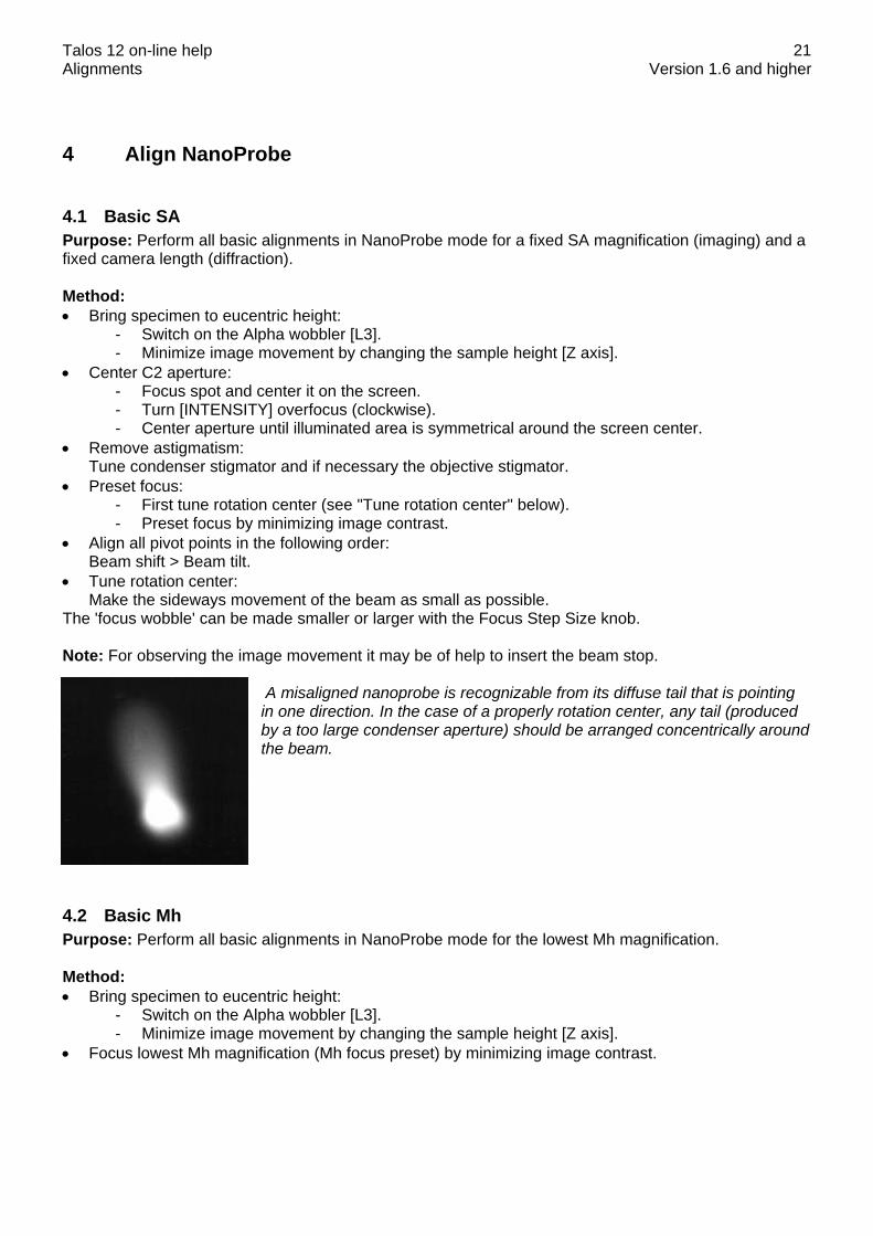
The 'focus wobble' can be made smaller or larger with the Focus Step Size knob. Note: For observing the image movement it may be of help to insert the beam stop.
A misaligned nanoprobe is recognizable from its diffuse tail that is pointing in one direction. In the case of a properly rotation center, any tail (produced by a too large condenser aperture) should be arranged concentrically around the beam.
4.2 Basic Mh Purpose: Perform all basic alignments in NanoProbe mode for the lowest Mh magnification. Method: • Bring specimen to eucentric height:
- Switch on the Alpha wobbler [L3]. - Minimize image movement by changing the sample height [Z axis].
• Focus lowest Mh magnification (Mh focus preset) by minimizing image contrast.

Talos 12 on-line help Alignments Version 1.6 and higher
22
Note: Explanation on using the P1 lens Because of the high magnifications used (and the resulting small field of view), it can be difficult to align the Mh magnifications (no light visible). The alignment procedure therefore provides a trick. It is possible to change the P1 lens (increase its current) by toggling the MF-X control to it (press the R2 button). When the P1 lens is made stronger, it reduces the effective magnification but has very little effect on image position and focus. This makes it possible to spread the beam (and actually see it more easily because of the lower magnification) and center it. Use the following procedure if the beam is not visible at the normal Mh magnification: • Toggle the MF-X control to the P1 lens (press R2). • Turn the MF-X knob a bit clock-wise. • Change the Intensity setting and see if the beam can be found. • Repeat the previous two steps until the beam is seen. Note that at very much changed P1 setting,
the image is partly blocked by an aperture (the differential pumping aperture between the column and the projection chamber) so not the whole screen can be illuminated.
• If the image is out of focus, focus it. • Toggle back to MF-X,Y control to the image shift [called Magn corr on the MF knobs] and center the
beam (and image). • Turn the magnification once up and down (this resets the P1 lens to its proper value). • Focus and center the image.
4.3 Basic Ml Purpose: Perform all basic alignments in NanoProbe mode for the highest Ml magnification. Method: • Bring specimen to eucentric height:
- Switch on the Alpha wobbler [L3]. - Minimize image movement by changing the sample height [Z axis].
• Focus highest Ml magnification (Ml focus preset) by minimizing image contrast. You can also start the DF-wobbler (press button on hand panel) and minimize the image movement.
4.4 Focus & Stigmate Beam nP Purpose: Make sure that a focused beam remains focused when spot size is changed. Importance: CONVENIENCE for keeping spot focus the same for all spot sizes, ESSENTIAL for proper operation of Intensity Zoom and Intensity Limit. Method: After focusing spot 3, all spots are focused in turn. The deviations in intensity setting from spot focus are stored for all spots. Procedure The alignment procedure consists of two steps : • One preparation step in which the beam is focused for spot size 3. • A step in which all spot sizes are focused. Note: The condenser system (C1 and C2 lenses) is normalized when the spot size is changed to make the spot setting better reproducible. Description The Intensity (C2 lens) and spot size (C1 lens) settings are not independent. In order to give the same effect for all spot sizes, the Intensity is changed whenever spot size is changed. In addition to the

Talos 12 on-line help Alignments Version 1.6 and higher
23
preprogrammed changes, individual instruments differ slightly in their relation between C1 and C2. The spot size-intensity calibration allows adjustment for this individual behaviour. For the Intensity Zoom and Intensity Limit functions this procedure defines the Intensity settings at which the beam is focused, which is essential for proper operation of these functions.

Talos 12 on-line help Alignments Version 1.6 and higher
24
5 Align HM-TEM
5.1 Basic SA Purpose: Perform all basic alignments in HM-TEM mode for a fixed SA magnification (imaging) and a fixed camera length (diffraction). Method: • Bring specimen to eucentric height:
- Switch on the Alpha wobbler [L3]. - Minimize image movement by changing the sample height [Z axis].
• Center C2 aperture: - Focus spot and center it on the screen. - Turn [INTENSITY] overfocus (clockwise). - Center aperture until illuminated area is symmetrical around the screen center.
• Remove astigmatism: Tune condenser stigmator and if necessary the objective stigmator.
• Preset focus: - First tune rotation center (see "Tune rotation center" below). - Preset focus in imaging mode by minimizing image contrast. - Preset focus in diffraction mode by focusing the objective aperture:
The focus is judged by looking at the edge of the objective aperture under the central beam.
• Align all pivot points in the following order: Beam shift > Image shift > Beam tilt > Diffraction shift.
• Tune rotation center: Make the sideways movement of the image as small as possible. The 'focus wobble' can be made smaller or larger with the Focus Step Size knob. Note: For observing the image movement it may be of help to insert the beam stop.
5.2 All SA magnifications Purpose: Align the image for each SA magnification. Method: Align all SA magnifications relative to the highest SA magnification.
Talos 12 on-line help Alignments Version 1.6 and higher
25
Notes: • The magnification system (projector lenses) is normalized when the magnification is changed to
make the image position better reproducible. • In case of thermionic emitters the spot can be larger than the screen size. In that case the spot can
be centered by finding the edges on either side of the spot and placing them symmetrical on both sides of the screen.
Description: The alignment uses a list of values that determine the shift between each SA magnification and the highest SA magnification.
5.3 Basic Mh Purpose: Perform all basic alignments in HM-TEM mode for the lowest Mh magnification. Method: • Bring specimen to eucentric height:
- Switch on the Alpha wobbler [L3]. - Minimize image movement by changing the sample height [Z axis].
• Focus lowest Mh magnification (Mh focus preset) by minimizing image contrast. • Align the Diffraction shift pivot point. Note: Explanation for using the P1 lens Because of the high magnifications used (and the resulting small field of view), it can be difficult to align the Mh magnifications (no light visible). The alignment procedure therefore provides a trick. It is possible to change the P1 lens (increase its current) by toggling the MF-X control to it (press the R2 button). When the P1 lens is made stronger, it reduces the effective magnification but has very little effect on image position and focus. This makes it possible to spread the beam (and actually see it more easily because of the lower magnification) and center it. Use the following procedure if the beam is not visible at the normal Mh magnification: • Toggle the MF-X control to the P1 lens (press R2). • Turn the MF-X knob a bit clock-wise. • Change the Intensity setting and see if the beam can be found. • Repeat the previous two steps until the beam is seen. Note that at very much changed P1 setting,
the image is partly blocked by an aperture (the differential pumping aperture between the column and the projection chamber) so not the whole screen can be illuminated.
• If the image is out of focus, focus it. • Toggle back to MF-X,Y control to the image shift [called Magn corr on the MF knobs] and center the
beam (and image). • Turn the magnification once up and down (this resets the P1 lens to its proper value). • Focus and center the image. In case of thermionic emitters the spot can be larger than the screen size. In that case the spot can be centered by finding the edges on either side of the spot and placing them symmetrical on both sides of the screen.

Talos 12 on-line help Alignments Version 1.6 and higher
26
5.4 Basic Ml Purpose: Perform all basic alignments in HM-TEM mode for the highest Ml magnification. Method: • Bring specimen to eucentric height:
- Switch on the Alpha wobbler [L3]. - Minimize image movement by changing the sample height [Z axis].
• Focus highest Ml magnification (Ml focus preset) by minimizing image contrast. You can also start the DF-wobbler (press button on hand panel) and minimize the image movement.
• Align the Diffraction shift pivot point.
5.5 All Mh magnifications Purpose: Align the Mh-magnification images with SA. Method: • Focus the image with the specimen stage in SA mode. • Focus and center the beam, still in SA mode. • Align the whole Mh range with the highest SA magnification. Notes: • The magnification system (projector lenses) is normalized when the magnification is changed to
make the image position better reproducible. • In the preparation step the P1 lens is maximized (with MF-X) to reduce the effective magnification.
Still, the beam (when wobbling in the next two steps) may be difficult to find. • In case of thermionic emitters the spot can be larger than the screen size. In that case the spot can
be centered by finding the edges on either side of the spot and placing them symmetrical on both sides of the screen.
Description: The alignment uses a list of values that determine the shift between each Mh magnification and the highest SA magnification.
5.6 All Ml magnifications Purpose: Align the Ml-magnification images with SA. Method: • Focus the image with the specimen stage in SA mode. • Focus and center the beam, still in SA mode. • Align the whole Ml range with the lowest SA magnification. Notes: The magnification system (projector lenses) is normalized when the magnification is changed to make the image position better reproducible. Description: The alignment uses a list of values that determine the shift between each Mh magnification and the highest SA magnification.
Talos 12 on-line help Alignments Version 1.6 and higher
27
5.7 All camera lengths Purpose: Align and focus the diffraction pattern for each camera length. Method: • Center and focus the diffraction pattern for the reference camera length. • Center and focus the diffraction pattern for all other camera lengths. Notes: • The reference camera length is the one used in the previous alignment procedure: "Basic HM-TEM
SA". • The magnification system (projector lenses) is normalized when the magnification is changed to
make the image position better reproducible. Description: The alignment uses two lists of values: • The first list of values determines the shift between each camera length and the reference camera
length. • A second list of values determines the focus difference between each camera length and the
reference camera length.
5.8 All SA magnifications - fine Note: The alignment All SA Magnifications - fine is only needed when ultimate focus accuracy is acquired. For normal use the alignment All SA Magnifications is sufficient. Purpose: Align and focus the image for each SA magnification. Method: Align and focus all SA magnifications relative to the highest SA magnification. Note: The magnification system (projector lenses) is normalized when the magnification is changed to make the image position better reproducible. Description: The alignment uses two lists of values: • A first list of values determines the shift between each SA magnification and the highest SA
magnification. • A second list of values determines the focus difference between each SA magnification and the
reference SA magnification. • In case of thermionic emitters the spot can be larger than the screen size. In that case the spot can
be centered by finding the edges on either side of the spot and placing them symmetrical on both sides of the screen.
5.9 All Mh magnifications - fine Note : The alignment All Mh Magnifications - fine is only needed when ultimate focus accuracy is acquired. For normal use the alignment All Mh Magnifications is sufficient. Purpose: Align the Mh-magnification images and find the difference in focus with the lowest Mh magnification. Method: • Focus and center image feature with the specimen stage in the highest SA magnification. • Align (relative to the highest SA magnification) and focus all Mh magnifications.

Talos 12 on-line help Alignments Version 1.6 and higher
28
Notes: • The magnification system (projector lenses) is normalized when the magnification is changed to
make the image position better reproducible. • In case of thermionic emitters the spot can be larger than the screen size. In that case the spot can
be centered by finding the edges on either side of the spot and placing them symmetrical on both sides of the screen.
Description: The alignment aligns the focus preset for Mh-mode and two lists of values: • A first list of values determines the shift between each Mh magnification and the lowest Mh
magnification. • A second list of values determines the focus difference between each Mh magnification and the
lowest Mh magnification.
5.10 All Ml magnifications - fine Note : The alignment All Ml Magnifications - fine is only needed when ultimate focus accuracy is acquired. For normal use the alignment All Ml Magnifications is sufficient. Purpose: Align the Ml-magnification images and find the difference in focus with the highest Ml magnification. Method: • Focus and center image feature with the specimen stage in the lowest SA magnification. • Align (relative to the lowest SA magnification) and focus all other Ml magnifications. Note: The magnification system (projector lenses) is normalized when the magnification is changed to make the image position better reproducible. Description: The alignment aligns the focus preset for Ml-mode and two lists of values: • A first list of values determines the shift between each Ml magnification and the highest Ml
magnification. • A second list of values determines the focus difference between each Ml magnification and the
highest Ml magnification.
5.11 Focus & Stigmate Beam uP Purpose: Make sure that a focused beam remains focused when spot size is changed. Importance: CONVENIENCE for keeping spot focus the same for all spot sizes, ESSENTIAL for proper operation of Intensity Zoom and Intensity Limit. Method: After focusing spot 3, all spots are focused in turn. The deviations in intensity setting from spot focus are stored for all spots. Procedure The alignment procedure consists of two steps : • One preparation step in which the beam is focused for spot size 3. • A step in which all spot sizes are focused. Note: The condenser system (C1 and C2 lenses) is normalized when the spot size is changed to make the spot setting better reproducible.

Talos 12 on-line help Alignments Version 1.6 and higher
29
Description The Intensity (C2 lens) and spot size (C1 lens) settings are not independent. In order to give the same effect for all spot sizes, the Intensity is changed whenever spot size is changed. In addition to the preprogrammed changes, individual instruments differ slightly in their relation between C1 and C2. The spot size-intensity calibration allows adjustment for this individual behavior. For the Intensity Zoom and Intensity Limit functions this procedure defines the Intensity settings at which the beam is focused, which is essential for proper operation of these functions.

Talos 12 on-line help Alignments Version 1.6 and higher
30
6 Align LM
6.1 Basic LM Purpose: Perform all basic alignments in LM mode for a fixed magnification (imaging) and a fixed camera length (diffraction). Method: • Bring specimen to eucentric height:
- Switch on the Alpha wobbler [L3]. - Minimize image movement by changing the sample height [Z axis].
• Center C2 aperture: - Focus spot and center it on the screen. - Turn [INTENSITY] overfocus (clockwise). - Center aperture until illuminated area is symmetrical around the screen center.
• Remove astigmatism: - Tune condenser stigmator by focusing the beam to a point. - Tune diffraction stigmator by making the halo symmetrical around the spot.
• Preset focus: - First tune rotation center (see "Tune rotation center" below). - Preset focus by minimizing image contrast.
• Align all pivot points in the following order: Beam shift > Image shift > Beam tilt > Diffraction shift.
• Tune rotation center: Make the sideways movement of the image as small as possible. The 'focus wobble' can be made smaller or larger with the Focus Step Size knob. Note: For observing the image movement it may be of help to insert the beam stop.
6.2 All LM magnifications Purpose: First align the LM image at the highest LM magnification with the SA image. Second align the image for each other LM magnification. Method: • Center image feature with the specimen stage in SA mode. • Align the whole LM range with the SA magnification. • Align (relative to the highest LM magnification) all LM magnifications. Notes: • Choose a proper image feature. A good example is the "tip of the A" in the center of a cross grating
(picture below).

Talos 12 on-line help Alignments Version 1.6 and higher
31
• The magnification system (projector lenses) is normalized when the magnification is changed to
make the image position better reproducible. Description: The alignment uses two types of values: • One single value determines the shift of the whole LM range relative to the smallest SA
magnification. • A list of values determines the shift between each LM magnification and the highest LM
magnification.
6.3 All LAD camera lengths Purpose: Align and focus the diffraction pattern for each LAD camera length. Method: • Center and focus the diffraction pattern for the reference camera length. • Center and focus the diffraction pattern for all other camera lengths. Notes: • The reference camera length is the one used in the previous alignment procedure: "Basic LM". • The magnification system (projector lenses) is normalized when the magnification is changed to
make the image position better reproducible. Description: The alignment uses two lists of values: • The first list of values determines the shift between each LAD camera length and the reference
camera length. • A second list of values determines the focus difference between each LAD camera length and the
reference camera length.
6.4 All LM magnifications - fine Note : The alignment All LM Magnifications - fine is only needed when ultimate focus accuracy is acquired. For normal use the alignment All LM Magnifications is sufficient. Purpose: First align and focus the LM image for the highest LM magnification. Second align and focus the image for all other LM magnifications.

Talos 12 on-line help Alignments Version 1.6 and higher
32
Method: • Center image feature with the specimen stage in LM mode at the highest magnification. • Align (relative to the highest LM magnification) and focus all LM magnifications. Notes: • Choose a proper image feature. A good example is the "tip of the A" in the center of a cross grating
(picture below).
• Focusing all LM magnifications by minimizing the image contrast is difficult. Here we use an
alternative: the beam tilt is wobbled and the image is focused by minimizing its movement. • The magnification system (projector lenses) is normalized when the magnification is changed to
make the image position better reproducible. Description: The alignment uses two types of values: • A first list of values determines the shift between each LM magnification and the highest LM
magnification. • A second list of values determines the focus difference between each LM magnification and the
highest LM magnification.
6.5 Focus & Stigmate Beam LM Purpose: Make sure that a focused beam remains focused when spot size is changed. Importance: CONVENIENCE for keeping spot focus the same for all spot sizes, ESSENTIAL for proper operation of Intensity Zoom and Intensity Limit. Method: After focusing spot 3, all spots are focused in turn. The deviations in intensity setting from spot focus are stored for all spots. Procedure The alignment procedure consists of two steps : • One preparation step in which the beam is focused for spot size 3. • A step in which all spot sizes are focused. Note: The condenser system (C1 and C2 lenses) is normalized when the spot size is changed to make the spot setting better reproducible.

Talos 12 on-line help Alignments Version 1.6 and higher
33
Description The Intensity (C2 lens) and spot size (C1 lens) settings are not independent. In order to give the same effect for all spot sizes, the Intensity is changed whenever spot size is changed. In addition to the preprogrammed changes, individual instruments differ slightly in their relation between C1 and C2. The spot size-intensity calibration allows adjustment for this individual behavior. For the Intensity Zoom and Intensity Limit functions this procedure defines the Intensity settings at which the beam is focused, which is essential for proper operation of these functions.

Talos 12 on-line help Alignments Version 1.6 and higher
34
7 Stigmators
7.1 Condenser (uP) / Condenser (nP) Purpose: Have no apparent beam shift when using the condenser stigmator. Method: The microscope contains a condenser stigmator to correct for beam astigmatism. When this stigmator is misaligned, adjustment of the stigmator setting will lead to an apparent beam shift. When the stigmator is aligned correctly, these shifts are compensated by an identical but opposite beam shift - this time using the beam deflection coils. In order to align the stigmator, it is necessary to determine the relation between a change in stigmator setting and the beam shift. This relation is determined in the procedure for aligning the stigmator. • Focus the image (TEM) or the beam (Probe). • Some current is set through the stigmator in the X direction. Recenter the beam. • Repeat the procedure for the Y direction. • Finally, stigmate the beam. No apparent beam shift should be visible anymore. Note: In TEM mode, it is not allowed to change the beam size. This makes sure that the alignment is performed in parallel mode. At low magnifications, it is better to move the specimen so a grid bar crossing is at the center and most of the beam perimeter is visible.
Grid bar crossing at the center.
7.2 Objective Purpose: Have no apparent image shift in HM mode nor apparent diffraction shift in LM mode when using the objective stigmator. Method: The microscope contains an objective stigmator to correct for astigmatism in HM image and LM diffraction. When this stigmator is misaligned, adjustment of the stigmator setting will lead to an apparent HM image shift (or LM diffraction shift). When the stigmator is aligned correctly, these shifts are compensated by an identical but opposite shift - this time using the image deflection coils. In order to align the stigmator, it is necessary to determine the relation between a change in stigmator setting and the HM image shift. This relation is determined in the procedure for aligning the stigmator. • Focus the image in HM mode. • Some current is set through the stigmator in the X direction. Recenter the image. • Repeat the procedure for the Y direction. • Finally, stigmate the image. No apparent image shift should be visible anymore.

Talos 12 on-line help Alignments Version 1.6 and higher
35
7.3 Diffraction Purpose: Have no apparent diffraction shift in HM mode nor apparent image shift in LM mode when using the diffraction stigmator. Method: The microscope contains a diffraction stigmator to correct for astigmatism in HM diffraction and LM image. When this stigmator is misaligned, adjustment of the stigmator setting will lead to an apparent HM diffraction shift / LM image shift. When the stigmator is aligned correctly, these shifts are compensated by an identical but opposite shift - this time using the image deflection coils. In order to align the stigmator, it is necessary to determine the relation between a change in stigmator setting and the LM image shift. This relation is determined in the procedure for aligning the stigmator. • Focus the image in LM mode. • Some current is set through the stigmator in the X direction. Recenter the image. • Repeat the procedure for the Y direction. • Finally, stigmate the image. No apparent image shift should be visible anymore. Note: In TEM mode, it is not allowed to change the beam size. This makes sure that the alignment is performed in parallel mode. At low magnifications, it is better to move the specimen so a grid bar crossing is at the center and most of the beam perimeter is visible.
Grid bar crossing at the center.
7.4 Condenser 3 fold The correction of astigmatism is a combination of a (normal) two-fold and a three-fold correction for both the condenser system and the imaging system. The latter must be aligned as well (as the two-fold stigmator) before performing this step for both three-fold condenser and objective astigmatism correction.
Talos 12 on-line help Alignments Version 1.6 and higher
36
8 Calibrate NanoProbe
8.1 Calibrate Trackball Purpose: Have the beam shift move in the same direction as the trackball. Method: • Shift the beam to the center of the screen. For this purpose the alignment value is used while the
user value is reset to zero. • Align the direction of the beam shift with respect to the movement by the trackball. When the
trackball is moved from left to right, the beam should also move from left to right on the screen. If the beam moves in a different direction, adjust the direction with the Multifunction Y knob.
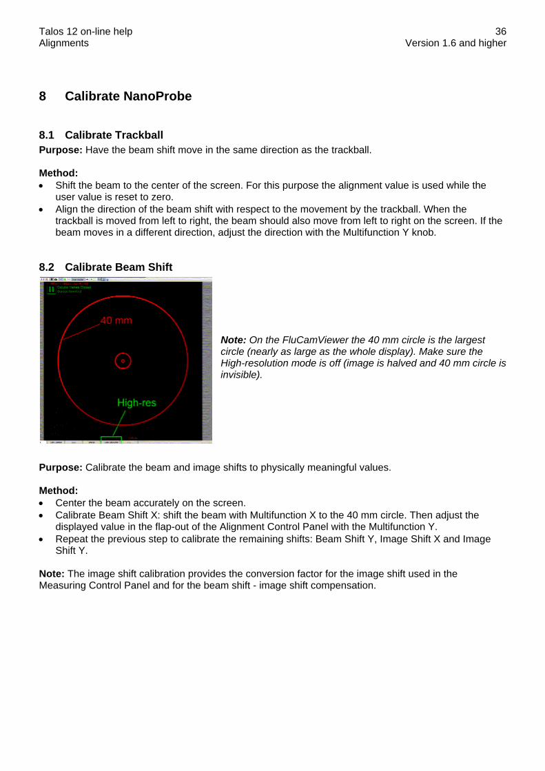
8.2 Calibrate Beam Shift Note: On the FluCamViewer the 40 mm circle is the largest circle (nearly as large as the whole display). Make sure the High-resolution mode is off (image is halved and 40 mm circle is invisible).
Purpose: Calibrate the beam and image shifts to physically meaningful values. Method: • Center the beam accurately on the screen. • Calibrate Beam Shift X: shift the beam with Multifunction X to the 40 mm circle. Then adjust the
displayed value in the flap-out of the Alignment Control Panel with the Multifunction Y. • Repeat the previous step to calibrate the remaining shifts: Beam Shift Y, Image Shift X and Image
Shift Y. Note: The image shift calibration provides the conversion factor for the image shift used in the Measuring Control Panel and for the beam shift - image shift compensation.

Talos 12 on-line help Alignments Version 1.6 and higher
37
8.3 Calibrate Beam Tilt Note: On the FluCamViewer the 40 mm circle is the largest circle (nearly as large as the whole display). Make sure the High-resolution mode is off (image is halved and 40 mm circle is invisible).
Purpose: Calibrate the beam tilts and image tilts (= diffraction shifts) to physically meaningful values. Method: Because few specimens provide the (large) d spacings appropriate for the small beam tilts obtained in LAD, it may not be possible to use a d spacing as calibration. The software therefore suggests to use the camera length value as a reference and simply calculate the angle corresponding to the shift to the 4 cm circle of the viewing screen. • Center the diffraction pattern accurately on the screen. • Calibrate Beam Tilt X: shift the center of the diffraction pattern with Multifunction X to the 40 mm
circle. Then adjust the displayed value in the flap-out of the Alignment Control Panel with the Multifunction Y.
• Repeat the previous step to calibrate the remaining shifts: Beam Tilt Y, Diffraction Shift X (Image Tilt X) and Diffraction Shift Y (Image Tilt Y).
Note: The diffraction shift calibration provides the conversion factor for the diffraction shift used in the Measuring Control Panel.
8.4 Image/Beam calibration Note: The microscope will sound a beep when the beam shift-image shift or one of the coils reaches its limit. The control above which is directly linked to the microscope displays the situation. Purpose: Keep the beam on the screen when the image is shifted. Method: • Shift the beam to the center of the screen. For this purpose the alignment value is used while the
user value is reset to zero. At the same time the image shift is set to zero. • Change the Image Shift X until the above control indicates a suitable shift, the microscope beeps (at
the limit of the image shift) or the beam moves off the screen (the latter typically happens when the calibration has not been done yet).
• Recenter the beam using the Multifunction X,Y. If the microscope beeped during the second step, continue, otherwise step back and repeat the second and third steps (so the final calibration is done with the image shift at its limit).
• Repeat the same procedure for the Image Shift Y. Note: The beam shift - image shift is used in the Image Settings Control Panel and in Low Dose.
Talos 12 on-line help Alignments Version 1.6 and higher
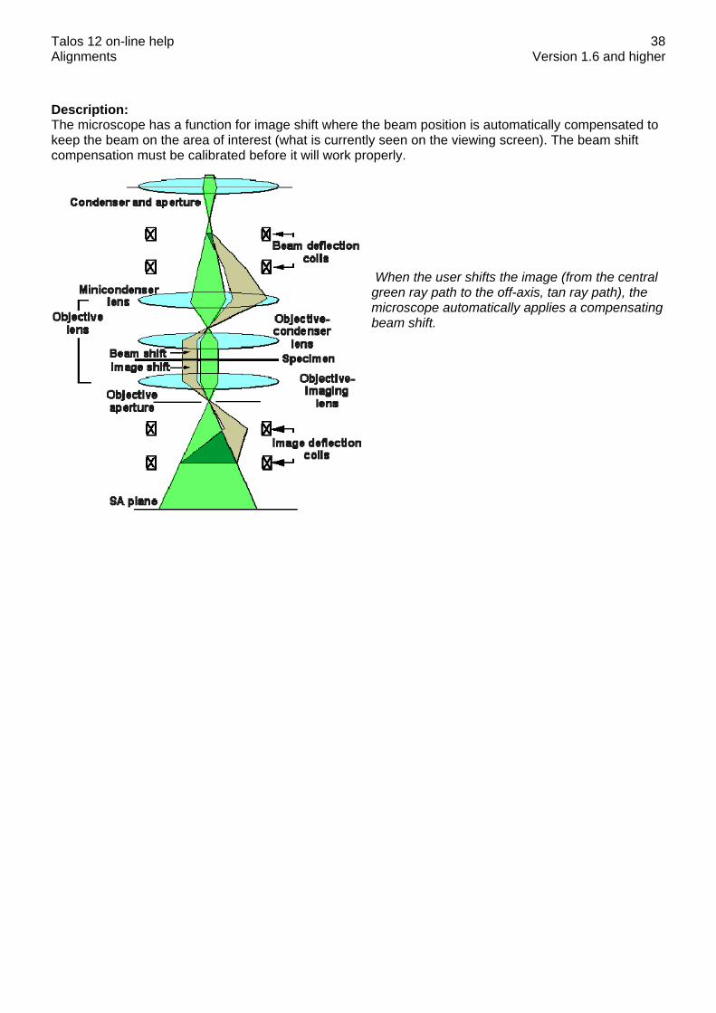
38
Description: The microscope has a function for image shift where the beam position is automatically compensated to keep the beam on the area of interest (what is currently seen on the viewing screen). The beam shift compensation must be calibrated before it will work properly.
When the user shifts the image (from the central green ray path to the off-axis, tan ray path), the microscope automatically applies a compensating beam shift.

Talos 12 on-line help Alignments Version 1.6 and higher
39
9 Calibrate HM-TEM
9.1 Calibrate Trackball Purpose: Have the beam shift move in the same direction as the trackball. Method: • Shift the beam to the center of the screen. For this purpose the alignment value is used while the
user value is reset to zero. • Align the direction of the beam shift with respect to the movement by the trackball. When the
trackball is moved from left to right, the beam should also move from left to right on the screen. If the beam moves in a different direction, adjust the direction with the Multifunction Y knob.
9.2 Calibrate Shifts Note: On the FluCamViewer the 40 mm circle is the largest circle (nearly as large as the whole display). Make sure the High-resolution mode is off (image is halved and 40 mm circle is invisible).
Purpose: Calibrate the beam and image shifts to physically meaningful values. Method: • Center the beam accurately on the screen. • Calibrate Beam Shift X: shift the beam with Multifunction X to the 40 mm circle. Then adjust the
displayed value in the flap-out of the Alignment Control Panel with the Multifunction Y. • Repeat the previous step to calibrate the remaining shifts: Beam Shift Y, Image Shift X and Image
Shift Y. Note: The image shift calibration provides the conversion factor for the image shift used in the Measuring Control Panel and for the beam shift - image shift compensation.

Talos 12 on-line help Alignments Version 1.6 and higher
40
9.3 Calibrate Tilts Note: On the FluCamViewer the 40 mm circle is the largest circle (nearly as large as the whole display). Make sure the High-resolution mode is off (image is halved and 40 mm circle is invisible).
Purpose: Calibrate the beam tilts and image tilts (= diffraction shifts) to physically meaningful values. Method: Because few specimens provide the (large) d spacings appropriate for the small beam tilts obtained in LAD, it may not be possible to use a d spacing as calibration. The software therefore suggests to use the camera length value as a reference and simply calculate the angle corresponding to the shift to the 4 cm circle of the viewing screen. • Center the diffraction pattern accurately on the screen. • Calibrate Beam Tilt X: shift the center of the diffraction pattern with Multifunction X to the 40 mm
circle. Then adjust the displayed value in the flap-out of the Alignment Control Panel with the Multifunction Y.
• Repeat the previous step to calibrate the remaining shifts: Beam Tilt Y, Diffraction Shift X (Image Tilt X) and Diffraction Shift Y (Image Tilt Y).
Note: The diffraction shift calibration provides the conversion factor for the diffraction shift used in the Measuring Control Panel.
9.4 Image/Beam calibration Note: The microscope will sound a beep when the beam shift-image shift or one of the coils reaches its limit. The control above which is directly linked to the microscope displays the situation. Purpose: Keep the beam on the screen when the image is shifted. Method: • Shift the beam to the center of the screen. For this purpose the alignment value is used while the
user value is reset to zero. At the same time the image shift is set to zero. • Change the Image Shift X until the above control indicates a suitable shift, the microscope beeps (at
the limit of the image shift) or the beam moves off the screen (the latter typically happens when the calibration has not been done yet).
• Recenter the beam using the Multifunction X,Y. If the microscope beeped during the second step, continue, otherwise step back and repeat the second and third steps (so the final calibration is done with the image shift at its limit).
• Repeat the same procedure for the Image Shift Y. Note: The beam shift - image shift is used in the Image Settings Control Panel and in Low Dose.

Talos 12 on-line help Alignments Version 1.6 and higher
41
Description: The microscope has a function for image shift where the beam position is automatically compensated to keep the beam on the area of interest (what is currently seen on the viewing screen). The beam shift compensation must be calibrated before it will work properly.
When the user shifts the image (from the central green ray path to the off-axis, tan ray path), the microscope automatically applies a compensating beam shift.

Talos 12 on-line help Alignments Version 1.6 and higher
42
10 Calibrate LM
10.1 Calibrate Trackball Purpose: Have the beam shift move in the same direction as the trackball. Method: • Shift the beam to the center of the screen. For this purpose the alignment value is used while the
user value is reset to zero. • Align the direction of the beam shift with respect to the movement by the trackball. When the
trackball is moved from left to right, the beam should also move from left to right on the screen. If the beam moves in a different direction, adjust the direction with the Multifunction Y knob.
10.2 Calibrate Shifts Note: On the FluCamViewer the 40 mm circle is the largest circle (nearly as large as the whole display). Make sure the High-resolution mode is off (image is halved and 40 mm circle is invisible).
Purpose: Calibrate the beam and image shifts to physically meaningful values. Method: • Center the beam accurately on the screen. • Calibrate Beam Shift X: shift the beam with Multifunction X to the 40 mm circle. Then adjust the
displayed value in the flap-out of the Alignment Control Panel with the Multifunction Y. • Repeat the previous step to calibrate the remaining shifts: Beam Shift Y, Image Shift X and Image
Shift Y. Note: The image shift calibration provides the conversion factor for the image shift used in the Measuring Control Panel and for the beam shift - image shift compensation.

Talos 12 on-line help Alignments Version 1.6 and higher
43
10.3 Calibrate Tilts Note: On the FluCamViewer the 40 mm circle is the largest circle (nearly as large as the whole display). Make sure the High-resolution mode is off (image is halved and 40 mm circle is invisible).
Purpose: Calibrate the beam tilts and image tilts (= diffraction shifts) to physically meaningful values. Method: Because few specimens provide the (large) d spacings appropriate for the small beam tilts obtained in LAD, it may not be possible to use a d spacing as calibration. The software therefore suggests to use the camera length value as a reference and simply calculate the angle corresponding to the shift to the 4 cm circle of the viewing screen. • Center the diffraction pattern accurately on the screen. • Calibrate Beam Tilt X: shift the center of the diffraction pattern with Multifunction X to the 40 mm
circle. Then adjust the displayed value in the flap-out of the Alignment Control Panel with the Multifunction Y.
• Repeat the previous step to calibrate the remaining shifts: Beam Tilt Y, Diffraction Shift X (Image Tilt X) and Diffraction Shift Y (Image Tilt Y).
Note: The diffraction shift calibration provides the conversion factor for the diffraction shift used in the Measuring Control Panel.
10.4 Image/beam calibration Note: The microscope will sound a beep when the beam shift-image shift or one of the coils reaches its limit. The control above which is directly linked to the microscope displays the situation. Purpose: Keep the beam on the screen when the image is shifted. Method: • Shift the beam to the center of the screen. For this purpose the alignment value is used while the
user value is reset to zero. At the same time the image shift is set to zero. • Change the Image Shift X until the above control indicates a suitable shift, the microscope beeps (at
the limit of the image shift) or the beam moves off the screen (the latter typically happens when the calibration has not been done yet).
• Recenter the beam using the Multifunction X,Y. If the microscope beeped during the second step, continue, otherwise step back and repeat the second and third steps (so the final calibration is done with the image shift at its limit).
• Repeat the same procedure for the Image Shift Y. Note: The beam shift - image shift is used in the Image Settings Control Panel and in Low Dose.

Talos 12 on-line help Alignments Version 1.6 and higher
44
Description: The microscope has a function for image shift where the beam position is automatically compensated to keep the beam on the area of interest (what is currently seen on the viewing screen). The beam shift compensation must be calibrated before it will work properly.
When the user shifts the image (from the central green ray path to the off-axis, tan ray path), the microscope automatically applies a compensating beam shift.

Talos 12 on-line help Alignments Version 1.6 and higher
45
11 Dyn. Conical DF Microprobe
11.1 Pivot point Purpose: Align beam tilt pivot point = make sure that the beam does not shift when it is tilted during dynamic conical dark-field imaging. Method: A tilting beam must remain centered on the specimen (so the tilt pivot point coincides with the specimen). The tilt wobble done by the microscope should give no beam shift, so only one spot should be visible in the image. Note: The AC beam tilt pivot point is sensitive to objective-lens focus.
11.2 Distortion Purpose: Make sure that the beam tilt describes a circle as seen in diffraction for proper dynamic conical dark-field imaging. Method: • Center the diffraction pattern. • Adjust the static beam tilt on the AC coils until the beam is at the 40 mm circle. • Remove the distortions in order to obtain a circular movement of the beam scanning around. Remark: At high tensions below 200 kV it is possible that the 40 mm circle cannot be reached. In that case one can either draw a smaller concentric circle on the FluCamViewer or increase the camera length with the magnification knob.
Note: On the FluCamViewer the 40 mm circle is the largest circle (nearly as large as the whole display). Make sure the High-resolution mode is off (image is halved and 40 mm circle is invisible).
11.3 Calibrate Tilt Purpose: Calibrate the AC beam tilt to physically meaningful values in dynamic conical dark field and ensure a match between static and dynamic conical dark field.
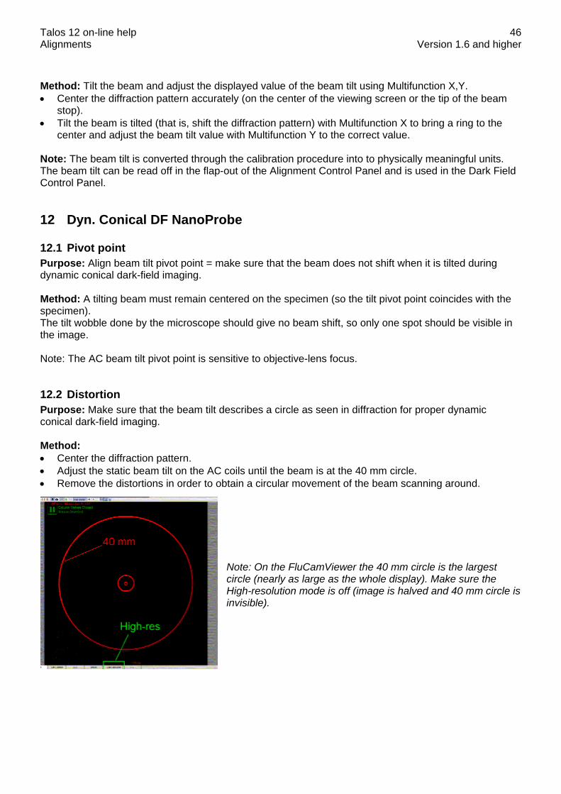
Talos 12 on-line help Alignments Version 1.6 and higher
46
Method: Tilt the beam and adjust the displayed value of the beam tilt using Multifunction X,Y. • Center the diffraction pattern accurately (on the center of the viewing screen or the tip of the beam
stop). • Tilt the beam is tilted (that is, shift the diffraction pattern) with Multifunction X to bring a ring to the
center and adjust the beam tilt value with Multifunction Y to the correct value. Note: The beam tilt is converted through the calibration procedure into to physically meaningful units. The beam tilt can be read off in the flap-out of the Alignment Control Panel and is used in the Dark Field Control Panel.
12 Dyn. Conical DF NanoProbe
12.1 Pivot point Purpose: Align beam tilt pivot point = make sure that the beam does not shift when it is tilted during dynamic conical dark-field imaging. Method: A tilting beam must remain centered on the specimen (so the tilt pivot point coincides with the specimen). The tilt wobble done by the microscope should give no beam shift, so only one spot should be visible in the image. Note: The AC beam tilt pivot point is sensitive to objective-lens focus.
12.2 Distortion Purpose: Make sure that the beam tilt describes a circle as seen in diffraction for proper dynamic conical dark-field imaging. Method: • Center the diffraction pattern. • Adjust the static beam tilt on the AC coils until the beam is at the 40 mm circle. • Remove the distortions in order to obtain a circular movement of the beam scanning around.
Note: On the FluCamViewer the 40 mm circle is the largest circle (nearly as large as the whole display). Make sure the High-resolution mode is off (image is halved and 40 mm circle is invisible).

Talos 12 on-line help Alignments Version 1.6 and higher
47
12.3 Calibrate Tilt Purpose: Calibrate the AC beam tilt to physically meaningful values in dynamic conical dark field and ensure a match between static and dynamic conical dark field. Method: Tilt the beam and adjust the displayed value of the beam tilt using Multifunction X,Y. • Center the diffraction pattern accurately (on the center of the viewing screen or the tip of the beam
stop). • Tilt the beam is tilted (that is, shift the diffraction pattern) with Multifunction X to bring a ring to the
center and adjust the beam tilt value with Multifunction Y to the correct value. Note: The beam tilt is converted through the calibration procedure into to physically meaningful units. The beam tilt can be read off in the flap-out of the Alignment Control Panel and is used in the Dark Field Control Panel.
Talos 12 on-line help Alignments Version 1.6 and higher
48
13 HM-STEM Note: TEM Imaging & Analysis (TIA) must be running for STEM alignment.
13.1 Preparation Purpose: Set up microscope for aligning the column in STEM. For STEM alignment a number of pre-conditions must be met, otherwise no proper alignment can be done : • STEM alignment can only be done once the Basic alignments (Gun -> Stigmators) have been
executed in full, following a top-down approach. • The specimen must be at the eucentric height. To do this properly, bring the specimen into focus with
the Z height of the specimen stage. (By doing it this way, you will attain a more reproducible setting than by using the alpha wobbler.)
• TEM Imaging & Analysis (TIA) must be running for STEM alignment. • The settings for the Preview view mode must be set so as to give an image size of 512 pixels and a
frame time of 5 seconds and the Search view mode to an image size of 256 and a frame time of approximately 3 seconds.
• Finally a STEM detector must be selected (and all other detectors deselected) in the STEM Detector Control Panel.
13.2 Intensity preset Purpose: Set up Intensity settings for focused beam in STEM. Method: • Bring the specimen to focus by adjusting the Z height. • Focus and stigmate the beam accurately for the default spot size (setting the intensity preset). • The microscope is switched to diffraction. Center the diffraction pattern. • Refocus and stigmate the beam for the default spot size with the aid of the shadow image. When the
magnification in the shadow image is infinite (no image information visible), the beam is properly focused.
• Repeat this procedure for all other spot sizes. • Several additional steps to set the condenser stigmator correction for beam-shift induced
astigmatism.
13.3 PP_BT Purpose: Align beam tilt pivot point = make sure that the beam does not shift when it is tilted. Method: A tilting beam must remain centered on the specimen (so the tilt pivot point coincides with the specimen). The tilt wobble done by the microscope should give no beam shift, so only one spot should be visible in the image. Important : • The specimen must be at the eucentric height. To do this properly, go to the Nanoprobe mode and
press the Eucentric Focus button. The objective lens current is now set to the proper value for Nanoprobe (provided Basic Nanoprobe SA has been aligned properly). Then bring the specimen into focus with the Z height of the specimen stage. (By doing it this way you will attain a more reproducible setting than by using the alpha wobbler.)
Talos 12 on-line help Alignments Version 1.6 and higher
49
Procedure The alignment procedure consists of three steps : • One preparation step for setting up the image. • Two steps in which the X and Y pivot points are aligned. Note: The tilt pivot point has already been set in Basic Nanoprobe SA. The alignment is repeated here to ensure that the rotation center alignment in STEM can be done properly.
13.4 Rotation center Purpose: Make sure that the beam is along the optical axis of the objective lens (to minimize lens aberrations and image movement during focusing). Method: • Bring the specimen to focus by adjusting the Z height. Focus and center the beam. • Check the beam tilt pivot point in x-direction. • Check the beam tilt pivot point in y-direction. • Align the rotation center: focus the beam and minimize sideways movement of the beam. The 'focus
wobble' can be made smaller or larger with the FOCUS STEP SIZE knob. • The beam defocus is reset. Center the beam. • Spread the beam and center the condenser aperture. Notes: • If the aperture required considerable re-alignment, one should step back through the procedure and
repeat from step 2 onwards.
13.5 Scan Pivot Point Warning: THIS ALIGNMENT WILL MAKE THE CURRENT STEM MAGNIFICATION INVALID. Only proceed if really needed. Purpose: Align scan pivot point = make sure that the beam does not tilt when it is shifted in STEM. Method: Shifting a beam parallel to itself means that it must always go through the front-focal point (= shift pivot point). This plane is conjugate to the back-focal (diffraction) plane and the alignment of the pivot point can thus be seen in diffraction. The shift 'wobble' done by the microscope should give no beam tilt, so the two central disks in the diffraction pattern should overlap.
13.6 Scan distortion adjustment Note: If you have access to Magnification Calibration, do not do the manual scan distortion adjustment but run the HM-STEM calibration procedure instead. Magnification Calibration will adjust the distortion if it finds the distortion exceeds 1% on the x-y ratio or 0.2° on the angle. It will do so far more accurately than can ever be done manually. It will also set the default rotation correctly. Purpose: Adjust the AC deflection coils settings so that the resulting STEM image has no distortions.

Talos 12 on-line help Alignments Version 1.6 and higher
50
Method: • First try to execute this alignment automatically by running the program 'Stem Distortion' that can be
found in the Startup menu. If not successful, proceed with the manual alignment. • Center and focus the beam. • Make a STEM image of a cross-grating specimen. • Set the scan rotation so that the horizontal lines of the cross-grating are horizontal in the STEM
image. The required rotation should be less than ~15 (see note below). • Remove the distortions. Multifunction knob X controls the trapezoid distortion (the vertical lines of the
grating are not perpendicular to the horizontal lines), while the Multifunction knob Y adjusts the relative strengths of the horizontal and vertical scans (rectangular distortion).
• Check the previous alignment with the image rotated by 90. Notes: • It is essential that the pivot point alignment has been done properly before the distortion adjustment
is done. • The cross-grating used must be inserted into the microscope in such a way that the horizontal and
vertical lines in the grating are roughly parallel to the horizontal and vertical in the image when the scan rotation (and the default scan rotation) is close to 0 (within ~15), otherwise the alignment is very difficult (requires many iterations). Judge whether the orientation of the cross-grating is suitable in the second or third step of the procedure. If the orientation is further away from 0, remove the specimen holder from the microscope and rotate the specimen until its orientation is suitable for this alignment.
• The distortions of the image may be judged more easily by drawing a square in the image. Click on the Image Selection Tool toolbar button in TIA , click in the top left quadrant of the image and drag the cursor to bottom right while keeping the Shift key on the keyboard pressed down (the latter forces the image selection drawn to remain square). It is then easy to count the number of cross-grating squares in the horizontal and vertical dimensions and making sure that the numbers are the same.
Description: The deflection coils used in the microscope are not all equal and exactly the same from one microscope to another. There are therefore alignment procedures that will result in adjustments that compensate for the variation in the coils. For the deflection coils used in TEM operation, the two adjustable parameters are the pivot points and the perpendicular correction. The pivot adjusts for the difference in strength between upper and lower coil (e.g. the X coil). The perpendicular correction adjusts for a rotation between the upper and lower coils (e.g. the upper and lower X coils) by adding a small deflection to the other lower coil (in that case the lower Y coil). For use in TEM this is sufficient. In STEM, however, additional adjustments are necessary, otherwise image distortions (stretch of one direction relative to the other and angular distortion) appear. These adjustments correct for the difference in strength between the X and Y coils and for any deviation from 90 between the X and Y coils. In principle this can be done both for the upper and lower coils separately but in practice this is too difficult to align and a single adjustment is sufficient.
13.7 Scan default rotation Note: If you have access to Magnification Calibration, do not do the scan default rotation adjustment but run the HM-STEM calibration procedure instead. Magnification Calibration will adjust the default rotation. It will do so far more accurately than can ever be done manually. Purpose: Have the STEM image (at 0 scan rotation) in the same orientation as the TEM image (on the viewing screen). Method: • Center and focus the beam on the viewing screen.

Talos 12 on-line help Alignments Version 1.6 and higher
51
• The beam is scanned so the scan frame is visible on the viewing screen. Change the rotation correction setting until the scan line (the fast scan direction) goes from left to right (W to E) on the screen and the scan frame (the slow scan direction) goes from top to bottom.
Notes: • TEM Imaging & Analysis (TIA) must be running for STEM alignment. • Increase the dwell time in the STEM imaging scan control panel if the scanning is too fast to
determine the scan direction.

Talos 12 on-line help Alignments Version 1.6 and higher
52
14 STEM MicroProbe Note: TEM Imaging & Analysis (TIA) must be running for STEM alignment.
14.1 Preparation Purpose: Set up microscope for aligning the column in STEM. For STEM alignment a number of pre-conditions must be met, otherwise no proper alignment can be done : • STEM alignment can only be done once the Basic alignments (Gun -> Stigmators) have been
executed in full, following a top-down approach. • The specimen must be at the eucentric height. To do this properly, bring the specimen into focus with
the Z height of the specimen stage. (By doing it this way, you will attain a more reproducible setting than by using the alpha wobbler.)
• TEM Imaging & Analysis (TIA) must be running for STEM alignment. • The settings for the Preview view mode must be set so as to give an image size of 512 pixels and a
frame time of 5 seconds and the Search view mode to an image size of 256 and a frame time of approximately 3 seconds.
• Finally a STEM detector must be selected (and all other detectors deselected) in the STEM Detector Control Panel.
14.2 Intensity preset Purpose: Set up Intensity settings for focused beam in STEM. Method: • Bring the specimen to focus by adjusting the Z height. • Focus and stigmate the beam accurately for the default spot size (setting the intensity preset). • The microscope is switched to diffraction. Center the diffraction pattern. • Refocus and stigmate the beam for the default spot size with the aid of the shadow image. When the
magnification in the shadow image is infinite (no image information visible), the beam is properly focused.
• Repeat this procedure for all other spot sizes.
14.3 PP_BT Purpose: Align beam tilt pivot point = make sure that the beam does not shift when it is tilted. Method: A tilting beam must remain centered on the specimen (so the tilt pivot point coincides with the specimen). The tilt wobble done by the microscope should give no beam shift, so only one spot should be visible in the image. Important : • The specimen must be at the eucentric height. To do this properly, go to the Microprobe mode and
press the Eucentric Focus button. The objective lens current is now set to the proper value for Microprobe (provided Basic Microprobe SA has been aligned properly). Then bring the specimen into focus with the Z height of the specimen stage. (By doing it this way you will attain a more reproducible setting than by using the alpha wobbler.)

Talos 12 on-line help Alignments Version 1.6 and higher
53
Procedure The alignment procedure consists of three steps : • One preparation step for setting up the image. • Two steps in which the X and Y pivot points are aligned. Note: The tilt pivot point has already been set in Basic Microprobe SA. The alignment is repeated here to ensure that the rotation center alignment in STEM can be done properly.
14.4 Rotation center Purpose: Make sure that the beam is along the optical axis of the objective lens (to minimize lens aberrations and image movement during focusing). Method: • Bring the specimen to focus by adjusting the Z height. Focus and center the beam. • Check the beam tilt pivot point in x-direction. • Check the beam tilt pivot point in y-direction. • Align the rotation center: spread the beam and minimize the image movement. The 'focus wobble'
can be made smaller or larger with the FOCUS STEP SIZE knob. • The beam defocus is reset. Center the beam. • Spread the beam and center the condenser aperture. Notes: • If the aperture required considerable re-alignment, one should step back through the procedure and
repeat from step 2 onwards.
14.5 Scan Pivot Point Warning: THIS ALIGNMENT WILL MAKE THE CURRENT STEM MAGNIFICATION INVALID. Only proceed if really needed. Purpose: Align scan pivot point = make sure that the beam does not tilt when it is shifted in STEM. Method: Shifting a beam parallel to itself means that it must always go through the front-focal point (= shift pivot point). This plane is conjugate to the back-focal (diffraction) plane and the alignment of the pivot point can thus be seen in diffraction. The shift 'wobble' done by the microscope should give no beam tilt, so the two central disks in the diffraction pattern should overlap.
14.6 Scan distortion adjustment Note: If you have access to Magnification Calibration, do not do the manual scan distortion adjustment but run the HM-STEM calibration procedure instead. Magnification Calibration will adjust the distortion if it finds the distortion exceeds 1% on the x-y ratio or 0.2° on the angle. It will do so far more accurately than can ever be done manually. It will also set the default rotation correctly. Purpose: Adjust the AC deflection coils settings so that the resulting STEM image has no distortions. Method: • First try to execute this alignment automatically by running the program 'Stem Distortion' that can be
found in the Startup menu. If not successful, proceed with the manual alignment.

Talos 12 on-line help Alignments Version 1.6 and higher
54
• Center and focus the beam. • Make a STEM image of a cross-grating specimen. • Set the scan rotation so that the horizontal lines of the cross-grating are horizontal in the STEM
image. The required rotation should be less than ~15 (see note below). • Remove the distortions. Multifunction knob X controls the trapezoid distortion (the vertical lines of the
grating are not perpendicular to the horizontal lines), while the Multifunction knob Y adjusts the relative strengths of the horizontal and vertical scans (rectangular distortion).
• Check the previous alignment with the image rotated by 90. Notes: • It is essential that the pivot point alignment has been done properly before the distortion adjustment
is done. • The cross-grating used must be inserted into the microscope in such a way that the horizontal and
vertical lines in the grating are roughly parallel to the horizontal and vertical in the image when the scan rotation (and the default scan rotation) is close to 0 (within ~15), otherwise the alignment is very difficult (requires many iterations). Judge whether the orientation of the cross-grating is suitable in the second or third step of the procedure. If the orientation is further away from 0, remove the specimen holder from the microscope and rotate the specimen until its orientation is suitable for this alignment.
• The distortions of the image may be judged more easily by drawing a square in the image. Click on the Image Selection Tool toolbar button in TIA , click in the top left quadrant of the image and drag the cursor to bottom right while keeping the Shift key on the keyboard pressed down (the latter forces the image selection drawn to remain square). It is then easy to count the number of cross-grating squares in the horizontal and vertical dimensions and making sure that the numbers are the same.
Description: The deflection coils used in the microscope are not all equal and exactly the same from one microscope to another. There are therefore alignment procedures that will result in adjustments that compensate for the variation in the coils. For the deflection coils used in TEM operation, the two adjustable parameters are the pivot points and the perpendicular correction. The pivot adjusts for the difference in strength between upper and lower coil (e.g. the X coil). The perpendicular correction adjusts for a rotation between the upper and lower coils (e.g. the upper and lower X coils) by adding a small deflection to the other lower coil (in that case the lower Y coil). For use in TEM this is sufficient. In STEM, however, additional adjustments are necessary, otherwise image distortions (stretch of one direction relative to the other and angular distortion) appear. These adjustments correct for the difference in strength between the X and Y coils and for any deviation from 90 between the X and Y coils. In principle this can be done both for the upper and lower coils separately but in practice this is too difficult to align and a single adjustment is sufficient.
14.7 Scan default rotation Note: If you have access to Magnification Calibration, do not do the scan default rotation adjustment but run the Microprobe-STEM calibration procedure instead. Magnification Calibration will adjust the default rotation. It will do so far more accurately than can ever be done manually. Purpose: Have the STEM image (at 0 scan rotation) in the same orientation as the TEM image (on the viewing screen). Method: • Center and focus the beam on the viewing screen. • The beam is scanned so the scan frame is visible on the viewing screen. Change the rotation
correction setting until the scan line (the fast scan direction) goes from left to right (W to E) on the screen and the scan frame (the slow scan direction) goes from top to bottom.

Talos 12 on-line help Alignments Version 1.6 and higher
55
Notes: • TEM Imaging & Analysis (TIA) must be running for STEM alignment. • Increase the dwell time in the STEM imaging scan control panel if the scanning is too fast to
determine the scan direction.

Talos 12 on-line help Alignments Version 1.6 and higher
56
15 LM-STEM Note: TEM Imaging & Analysis (TIA) must be running for STEM alignment.
15.1 Preparation Purpose: Set up microscope for aligning the column in LM-STEM. For STEM alignment a number of pre-conditions must be met, otherwise no proper alignment can be done : • STEM alignment can only be done once the Basic alignments (Gun -> Stigmators) have been
executed in full, following a top-down approach. • The settings for the Preview view mode must be set so as to give an image size of 512 pixels and a
frame time of 5 seconds and the Search view mode to an image size of 256 and a frame time of approximately 3 seconds.
• Finally a STEM detector must be selected (and all other detectors deselected) in the STEM Detector Control Panel.
15.2 Intensity preset Purpose: Set up Intensity settings for focused beam in LM-STEM. Method: • Bring the specimen to eucentric height and center the beam. • Focus the beam for all spot sizes.
15.3 Scan Pivot Point Warning: THIS ALIGNMENT WILL MAKE THE CURRENT STEM MAGNIFICATION INVALID. Only proceed if really needed. Purpose: Align scan pivot point = make sure that the beam does not tilt when it is shifted in LM-STEM Method: Shifting a beam parallel to itself means that it must always go through the front-focal point (= shift pivot point). This plane is conjugate to the back-focal (diffraction) plane and the alignment of the pivot point can thus be seen in diffraction. The shift 'wobble' done by the microscope should give no beam tilt, so the two central disks in the diffraction pattern should overlap. Note: Because of the large shifts of the beam (in LM-STEM) it is possible that one of the wobble directions (or even both) is blocked by the specimen (grid). If this is the case, either move the specimen around a bit or retract the holder slightly (about 1 cm) or to the parking position (retract it out until you can turn it somewhat so it stays out). Retracting slightly is preferred because there is less risk of a vacuum leak when re-inserting the holder again.
15.4 Align Diffraction Pattern Purpose: Make sure the diffraction pattern is centered properly on the viewing screen.

Talos 12 on-line help Alignments Version 1.6 and higher
57
Method: Center the diffraction pattern on the screen. Since the position of the pattern is affected by a number of factors such as condenser-aperture position and rotation center, while the shift to the detector is reproducible (not affected by hysteresis), the only requirement later is to make sure the diffraction pattern is centered at the screen center (with the off-axis shift not active) and then switch the off-axis shift on in order to have the pattern properly centered on the BF-DF detector. Procedure The alignment procedure consists of one step in which the LAD diffraction pattern is centered on the screen. Note: In LM-STEM only one camera length is used.
15.5 Scan distortion adjustment Note: If you have access to Magnification Calibration, do not do the manual scan distortion adjustment but run the LM-STEM calibration procedure instead. Magnification Calibration will adjust the distortion if it finds the distortion exceeds 1% on the x-y ratio or 0.2° on the angle. It will do so far more accurately than can ever be done manually. It will also set the default rotation correctly. Purpose: Adjust the AC deflection coils settings so that the resulting STEM image has no distortions. Method: • First try to execute this alignment automatically by running the program 'Stem Distortion' that can be
found in the Startup menu. If not successful, proceed with the manual alignment. • Center and focus the beam. • Make a STEM image of a cross-grating specimen. • Set the scan rotation so that the horizontal lines of the cross-grating are horizontal in the STEM
image. The required rotation should be less than ~15 (see note below). • Remove the distortions. Multifunction knob X controls the trapezoid distortion (the vertical lines of the
grating are not perpendicular to the horizontal lines), while the Multifunction knob Y adjusts the relative strengths of the horizontal and vertical scans (rectangular distortion).
• Check the previous alignment with the image rotated by 90. Notes: • It is essential that the pivot point alignment has been done properly before the distortion adjustment
is done. • The cross-grating used must be inserted into the microscope in such a way that the horizontal and
vertical lines in the grating are roughly parallel to the horizontal and vertical in the image when the scan rotation (and the default scan rotation) is close to 0 (within ~15), otherwise the alignment is very difficult (requires many iterations). Judge whether the orientation of the cross-grating is suitable in the second or third step of the procedure. If the orientation is further away from 0, remove the specimen holder from the microscope and rotate the specimen until its orientation is suitable for this alignment.
• The distortions of the image may be judged more easily by drawing a square in the image. Click on the Image Selection Tool toolbar button in TIA , click in the top left quadrant of the image and drag the cursor to bottom right while keeping the Shift key on the keyboard pressed down (the latter forces the image selection drawn to remain square). It is then easy to count the number of cross-grating squares in the horizontal and vertical dimensions and making sure that the numbers are the same.
Description: The deflection coils used in the microscope are not all equal and exactly the same from one microscope to another. There are therefore alignment procedures that will result in adjustments that compensate for the variation in the coils. For the deflection coils used in TEM operation, the two adjustable parameters
Talos 12 on-line help Alignments Version 1.6 and higher
58
are the pivot points and the perpendicular correction. The pivot adjusts for the difference in strength between upper and lower coil (e.g. the X coil). The perpendicular correction adjusts for a rotation between the upper and lower coils (e.g. the upper and lower X coils) by adding a small deflection to the other lower coil (in that case the lower Y coil). For use in TEM this is sufficient. In STEM, however, additional adjustments are necessary, otherwise image distortions (stretch of one direction relative to the other and angular distortion) appear. These adjustments correct for the difference in strength between the X and Y coils and for any deviation from 90 between the X and Y coils. In principle this can be done both for the upper and lower coils separately but in practice this is too difficult to align and a single adjustment is sufficient.
15.6 Scan default rotation Note: If you have access to Magnification Calibration, do not do the manual scan default rotation adjustment but run the LM-STEM calibration procedure instead. Magnification Calibration will adjust the default rotation. It will do so far more accurately than can ever be done manually. Purpose: Define the rotation correction for LM-STEM imaging so that the LM-STEM image is displayed with the same orientation as the HM-STEM image. Method: • Center the diffraction pattern. • Make an LM-STEM image of the specimen. • Move the specimen from left to right with the stage track ball. Adjust the rotation correction until the
features in the image also move from left to right. Notes: • TEM Imaging & Analysis (TIA) must be running for STEM alignment. • Increase the dwell time in the STEM imaging scan control panel if the scanning is too fast to
determine the scan direction.

Talos 12 on-line help Alignments Version 1.6 and higher
59
16 Phase plate
16.1 Phase plate alignment with the halo method Purpose: Basic alignments for phase plate usage in HM-TEM mode (nanoprobe). • Fine tune diffraction lens at highest camera length to focus accurately on phase plate plane. • Fine tune beam shift pivot points, such that pivot points accurately coincide with phase plate plane. Method: Starting position is in low magnification SA mode (nanoprobe) with the objective lens at eucentric focus. Preparation step: • Remove the specimen from the beam and remove the SA aperture. • Center C2 aperture:
o Focus spot and center it on the screen. o Turn [INTENSITY] overfocus (clockwise). o Center aperture until the illuminated area is symmetrical around the screen center.
• Remove astigmatism by tuning condenser stigmator to make illuminating beam round. • Insert the phase plate. Set on-plane condition: The on-plane condition can be recognized in diffraction mode by observing the scattering of the electron beam by the phase plate. This scattering is observed as a halo surrounding the electron beam (diffraction lens in underfocus). First this halo is searched for at intermediate camera length. Once it is observed, this halo must be confined to a small disk (1cm on flu screen) by tuning the diffraction lens. At the same time the central beam must be focused to a small spot using the condenser system.
Example of the scattering seen as a halo around the electron beam at intermediate camera lengths.
Fine focus phase plate: Go to the largest camera length to observe the halo.

Talos 12 on-line help Alignments Version 1.6 and higher
60
Example of the scattering seen as a halo around the electron beam at the largest camera length.
Tune the diffraction lens such that the halo just disappears. Meanwhile tune the condenser system such to keep the central beam focused. Astigmatism of the halo can be removed with the diffraction stigmator.
The shape of the halo around the spot can be tuned with the diffraction stigmator.
Astigmatism of the central beam can be removed with the condenser stigmator. In the on-plane condition, a correction value can be determined for the diffraction lens (at the largest camera length). To this aim, the diffraction lens is focused such that the smallest beam spot is observed. This spot coincides with the phase plate plane. Set beam shift pivot points: The beam shift pivot points are aligned with respect to the phase plate plane (largest camera length). They should be aligned for minimum movement of the halo. The spot movement should be ignored.
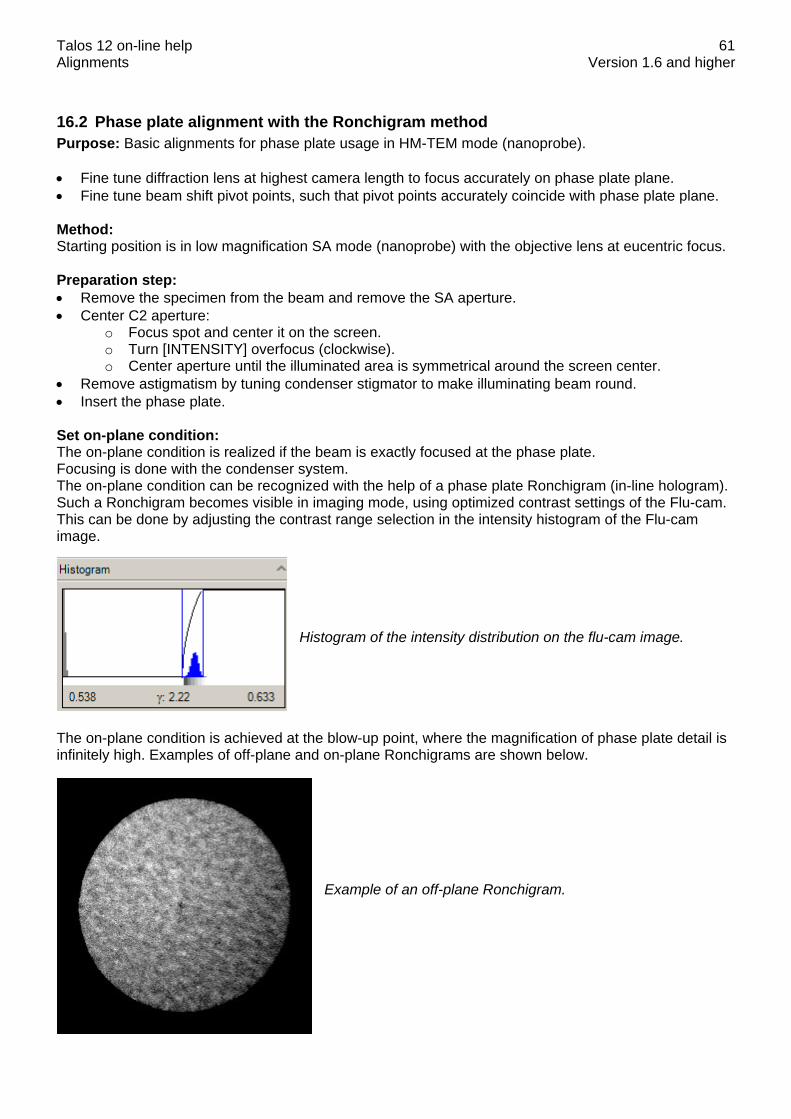
Talos 12 on-line help Alignments Version 1.6 and higher
61
16.2 Phase plate alignment with the Ronchigram method Purpose: Basic alignments for phase plate usage in HM-TEM mode (nanoprobe). • Fine tune diffraction lens at highest camera length to focus accurately on phase plate plane. • Fine tune beam shift pivot points, such that pivot points accurately coincide with phase plate plane. Method: Starting position is in low magnification SA mode (nanoprobe) with the objective lens at eucentric focus. Preparation step: • Remove the specimen from the beam and remove the SA aperture. • Center C2 aperture:
o Focus spot and center it on the screen. o Turn [INTENSITY] overfocus (clockwise). o Center aperture until the illuminated area is symmetrical around the screen center.
• Remove astigmatism by tuning condenser stigmator to make illuminating beam round. • Insert the phase plate. Set on-plane condition: The on-plane condition is realized if the beam is exactly focused at the phase plate. Focusing is done with the condenser system. The on-plane condition can be recognized with the help of a phase plate Ronchigram (in-line hologram). Such a Ronchigram becomes visible in imaging mode, using optimized contrast settings of the Flu-cam. This can be done by adjusting the contrast range selection in the intensity histogram of the Flu-cam image.
Histogram of the intensity distribution on the flu-cam image.
The on-plane condition is achieved at the blow-up point, where the magnification of phase plate detail is infinitely high. Examples of off-plane and on-plane Ronchigrams are shown below.
Example of an off-plane Ronchigram.

Talos 12 on-line help Alignments Version 1.6 and higher
62
Example of an on-plane Ronchigram.
Fine focus phase plate: In the on-plane condition, a correction value can be determined for the diffraction lens (at the largest camera length). To this aim, the diffraction lens is focused such that the smallest beam spot is observed. This spot coincides with the phase plate plane. Set beam shift pivot points: The beam shift pivot points are aligned with respect to the phase plate plane (largest camera length). A coarse pivot point alignment is done in diffraction mode. For better visibility of the beam spots, set the flu-cam at 'High Contrast' setting. A precise pivot point alignment is done in imaging mode, using a phase plate Ronchigram.