standard operating procedure (sop) - sample documentation ... · standard operating procedure (sop)...
TRANSCRIPT

SDMSDocID 2030061
2030061
STANDARD OPERATINGPROCEDURE
SAMPLE DOCUMENTATION ANDTRACKING
SUNRISE MOUNTAIN LANDFILLCLARK COUNTY, NEVADA
Prepared for:
Republic DUMPCo770 East Sahara Avenue
Las Vegas, Nevada 89104(702) 644-4594
Prepared by:
SCS ENGINEERS2702 North 44th Street
Suite 105BPhoenix, Arizona 85008
(602) 840-2596
March 31,2000File No. 10.99007.01
Standard Operating Procedure (SOP)
Introduction
This SOP has been developed in accordance with the United States EnvironmentalProtection Agency (EPA) approved Sampling and Analysis Plan (SAP) and the approvedLandfill Assessment Work Plan both dated February 29, 2000 for the current and on-going activities at the Sunrise Mountain Landfill in Las Vegas, Nevada. The purpose andscope of this SOP is to develop a standard for the documentation, labeling. Chain ofCustody1QOC), packaging, an^storageofsaninles^obtained from sampling events at theSunrise Mountain Landfill. This SO"P coversthe Assessment of the Existing Final CoverSoils, Hydrogeological Exploratory Drilling, Lagoon Exploratory Drilling, GroundwaterSampling, Waste Sampling, and Landfill Gas Characterization. The standards set forth inthis document are to be adhered to at all times and for all sampling events. Allcontractors operating on the Sunrise Mountain Landfill who must perform sampling willbe required to fulfill all requirements of this SOP.
Assessment of the Existing Final Cover Soils
Procedure
The existing final cover soils will be assessed by using the test pit/trenching and shallowboring methods as discussed in subtask 3.4.3.3 of the Final Landfill Assessment WorkPlan and Sections 1.5 and 1.6.2 of the SAP. Fourteen test pit/trenches will be excavatedprior to drilling the shallow borings.
Test Pit/Trench
Test pit/trench numbers will be assigned by the Responsible Person (RP) and will benumbered sequentially starting at the next available number from previous test pit/trenchactivities. The test pit/trenches will be located by coordinates using the globalpositioning system (GPS). Coordinates will be recorded on the attached Test Pit/TrenchLog.
The test pit/trenches will provide data on the interface between the cover and the wasteon a larger scale than the shallow borings are capable of providing. Specifically,observations will be made of the following:
• Variation in depth to the cover/waste interface,• The degree of trash embedded in the cover material,• The construction practices used to place the cover,• The identification of any oversized material (i.e., large stones), and• Documentation shall include the above observations and the requirements in
Section 1.5.3 of the SAP.
Sunrise Mountain Landfill ISample DocumentationMarch 31, 2000
The test pit/trench will be logged on the attached Test Pit/Trench Log. Landfill gasmonitoring will be conducted in accordance with Section 4.5.3 of the SAP and recordedon the attached Field Log for Landfill Gas Monitoring. The locations of the testpit/trenches will be distributed such that four pits will be excavated on the upper deck ofthe Top Deck Area, four on the side-slopes (sidewalls) of the Top Deck Area, four on theLower Southern Flats Area, and two in the Eastern Perimeter Area. Two of the locationson the Top Deck Area will coincide with areas where cracking has been observed in thecover, as defined by the BLM's GIS coordinate data.
Shallow Boring
Undisturbed core archive samples representing the entire depth of the final cover soilswill be collected through shallow boring and will be identified with a unique samplingnumber (this includes the location and borehole number, see below), coordinates fromGPS unit, represented sample depth, date and time, sample collector (Refer to Section1.6.2.2 of the SAP). Each one of the undisturbed core samples will be stored asprescribed below. The shallow boring will be logged on the attached Shallow BoringLog. Cover soil depths will be observed from the core sample collected and verified witha measurement from the borehole. Landfill gas monitoring will be conducted at eachshallow boring in accordance with Section 4.5.3 of the SAP and recorded on the attachedField Log for Landfill Gas Monitoring.
Visual observation and logging will consist of the following:
• Identifying and marking the core with a unique sample number• Date and time of core sample, sample collector• Visual observation of soil,• Percent recovery of the core,• Type of soil,• Color variation,• Moisture content,• Type of waste material encountered,• Cover soil depths, measured from the core (represented sample depth),• Cover soil depth, measured from the borehole,• Survey coordinates from GPS unit, and• All other documentation required in Section 1.6.2.2 of the SAP will be recorded
on the attached Field Log for Geotechnical Sampling and Shallow BoringObservation and/or the Shallow Boring Log.
Samples for geotechnical testing will be taken at ten percent of the shallow boringlocations. Special considerations are to be noted on the upper deck of the top deck areaand western side of the of the lower southern flats areas as noted in Section 1.6.2.2 of theSAP. Waste samples will also be taken at prescribed locations as described in subtask3.4.4.5 of the Landfill Assessment Work Plan (see Waste Sampling in this SOP).Shallow borings will be terminated at six inches into waste unless a landfill gas sampleprobe is to be installed in that location. All abandoned borings will be filled with drill
Sunrise Mountain Landfill 2Sample DocumentationMarch 31, 2000
cuttings to within three feet of the ground surface. A three-foot continuous bentonitecolumn will be placed in the upper three feet to seal the boring. The attached Soil TestTracking Log will be completed each day to identify the sampling activities. Theattached Soil Sample Request Record will be used as the COC for the geotechnicalsamples sent for laboratory testing. The RP or Assistant Responsible Person (ARP) willcheck these forms for accuracy and consistency and initial each form. After review andapproval, the RP or the ARP will enter the geotechnical sample numbers on the MasterSampling Log, prior to shipping the samples to the laboratory.
A laboratory as specified in Section 7.2 of the SAP will perform the geotechnical testsidentified below in Groups 1, 2, 3, and 4. The Sand Cone (ASTM D1556) and SoilMoisture Test (ASTM D2216) will be performed on-site by qualified personnel. Dataduring the performance of the geotechnical tests conducted on-site (sand cone and soilmoisture) will be recorded on the attached Sand Cone/Soil Moisture Record. Finalresults from the sand cone and soil moisture tests will be recorded on the Soil TestTracking Record. As the geotechnical testing results come back from the laboratory, theresults will be recorded or attached as appropriate to the Soil Test Tracking Log. Afterthe Soil Test Tracking Log is complete (all test data received for each soil sample listedon the Log), the completion date will be entered on the Master Sampling Log.
Multiple shallow borings within a 10-foot diameter of the original shallow boring at eachlocation may have to be sampled to obtain adequate sample volume (weight) forgeotechnical testing. Samples collected from these multiple shallow borings within thedepths and diameter specified in subtask 3.4.3.3 of the Landfill Assessment Work Planmay be composited to obtain the required sample volume (weight) for geotechnicaltesting. The composited samples may be placed in 5-gallon plastic containers with lids.The geotechnical testing to be performed is as follows:
Group 1 Testing: Soil Classification, consists of 10% of the shallow borings:
• Classifications of Soil for Engineering Purposes (ASTM D2487)• Particle Size Distribution (ASTM D422-63)• Atterberg Limits (ASTM D4318)• Calcium Carbonate Content (ASTM D4373-90)
A minimum of 33 Ibs of soil should be obtained for Group 1 laboratory testing.
Group 2 Testing: Compaction, consists of 50% of the Group 1 Tests:
• Standard Proctor (ASTM D698)• Modified Proctor (ASTM D1557)• Sand Cone (ASTM D1556) (on-site test)• Moisture Content (ASTM D2216) (on-site test)
A minimum of 97 Ibs of soil should be obtained for Group 2 laboratory testing (includesadequate sample for Group 1 and 2 Testing).
Sunrise Mountain Landfill 3Sample DocumentationMarch 31 , 2000
Group 3 Testing: Hydraulic Properties, consists of 50% of the Group 2 Tests:
• Specific Gravity (ASTM D854)• Min./Max Density (ASTM D4253)• Saturated Hydraulic Conductivity (ASTM D2434)• Saturated Hydraulic Conductivity (ASTM D5084)• Moisture Retention Curve (Klute 1986)
A minimum of 172 Ibs of soil should be obtained for Group 3 laboratory testing (includesadequate sample for Group 1, 2, 3, and 4 Testing, except Moisture Retention Curve). Aminimum of 64 Ibs of soil should be obtained for Moisture Retention Curve analysis.
Group 4 Testing: Soil Strength, consists of 50% of the Group 2 Tests:
• Consolidated Drained Triaxial Compression (ASTM D4767)
A minimum of 172 Ibs of soil should be obtained for Group 4 laboratory testing (includesadequate sample for Group 1,2, 3, and 4 Testing).
The weights listed above are based on samples being predominately fine-grained soilswith minor aggregate content up to 1-inch in diameter. If the soil is gravelly and/orcontains significant quantities of larger aggregate, then the sample collector shouldconsult with the RP to possibly increase the weight of sample collected.
Duplicate samples will also be obtained and tested for the lesser often percent of eachtest grouping or one per day per Section 6.8 of the SAP.
In addition, each shallow boring will be observed by a qualified geologist or engineer andobservations will be recorded on the attached Shallow Boring Log and/or Field Log forGeotechnical Sampling and Shallow Boring Observation. At a minimum theseobservations will include the following:
• Color, type and odor or smell of waste encountered• Discolored soils• Depth of soil cover• Percent recovery of the core• Type of soil in accordance with USCS• Moisture conditions• Oversize and type of rock encountered
Sampling device-cleaning procedures to be performed after each sampling event areoutlined in Section 6.2.4 of the SAP.
Sunrise Mountain LandfillSample DocumentationMarch 31 , 2000
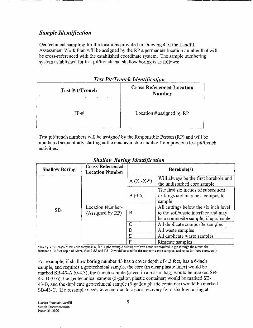
Sample Identification
Geotechnical sampling for the locations provided in Drawing 4 of the LandfillAssessment Work Plan will be assigned by the RP a permanent location number that willbe cross-referenced with the established coordinate system. The sample numberingsystem established for test pit/trench and shallow boring is as follows:
Test Pit/Trench Identification
Test Pit/Trench
TP-#
Cross Referenced LocationNumber
Location # assigned by RP
Test pit/trench numbers will be assigned by the Responsible Person (RP) and will benumbered sequentially starting at the next available number from previous test pit/trenchactivities.
Shallow Boring Identification
Shallow Boring
SB-
Cross-ReferencedLocation Number
Location Number-Assigned by RP)
Borehole(s)
A(X,-X2*)
B (0-6)
B
CDEF
Will always be the first borehole andthe undisturbed core sampleThe first six inches of subsequentdrillings and may be a compositesampleAll cuttings below the six inch levelto the soil/waste interface and maybe a composite sample, if applicableAll duplicate composite samplesAll waste samplesAll duplicate waste samplesRinseate samples
*Xi-X2 is the length of the core sample (i.e., 0-4.3 (for example below) or if two cores are required to get through the cover, forinstance a 10-foot depth of cover, then 0-5.5 and 5.5-10 would be used for the respective core samples, and so on for three cores, etc.).
For example, if shallow boring number 43 has a cover depth of 4.3 feet, has a 6-inchsample, and requires a geotechnical sample, the core (in clear plastic liner) would bemarked SB-43-A (0-4.3), the 6-inch sample (saved in a plastic bag) would be marked SB-43- B (0-6), the geotechnical sample (5-gallon plastic container) would be marked SB-43-B, and the duplicate geotechnical sample (5-gallon plastic container) would be markedSB-43-C. If a resample needs to occur due to a poor recovery for a shallow boring at
Sunrise Mountain LandfillSample DocumentationMarch 31,2000
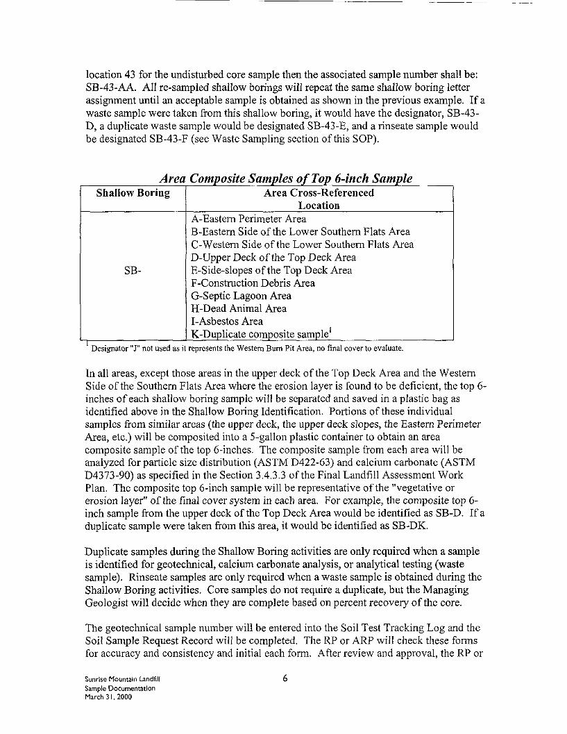
location 43 for the undisturbed core sample then the associated sample number shall be:SB-43-AA. All re-sampled shallow borings will repeat the same shallow boring letterassignment until an acceptable sample is obtained as shown in the previous example. If awaste sample were taken from this shallow boring, it would have the designator, SB-43-D, a duplicate waste sample would be designated SB-43-E, and a rinseate sample wouldbe designated SB-43-F (see Waste Sampling section of this SOP).
Area Composite Samples of Top 6-inch SampleShallow Boring Area Cross-Referenced
Location
SB-
A-Eastern Perimeter AreaB-Eastern Side of the Lower Southern Flats AreaC-Western Side of the Lower Southern Flats AreaD-Upper Deck of the Top Deck AreaE-Side-slopes of the Top Deck AreaF-Construction Debris AreaG-Septic Lagoon AreaH-Dead Animal AreaI-Asbestos AreaK-Duplicate composite sample
Designator "J" not used as it represents the Western Bum Pit Area, no final cover to evaluate.
In all areas, except those areas in the upper deck of the Top Deck Area and the WesternSide of the Southern Flats Area where the erosion layer is found to be deficient, the top 6-inches of each shallow boring sample will be separated and saved in a plastic bag asidentified above in the Shallow Boring Identification. Portions of these individualsamples from similar areas (the upper deck, the upper deck slopes, the Eastern PerimeterArea, etc.) will be composited into a 5-gallon plastic container to obtain an areacomposite sample of the top 6-inches. The composite sample from each area will beanalyzed for particle size distribution (ASTM D422-63) and calcium carbonate (ASTMD4373-90) as specified in the Section 3.4.3.3 of the Final Landfill Assessment WorkPlan. The composite top 6-inch sample will be representative of the "vegetative orerosion layer" of the final cover system in each area. For example, the composite top 6-inch sample from the upper deck of the Top Deck Area would be identified as SB-D. If aduplicate sample were taken from this area, it would be identified as SB-DK.
Duplicate samples during the Shallow Boring activities are only required when a sampleis identified for geotechnical, calcium carbonate analysis, or analytical testing (wastesample). Rinseate samples are only required when a waste sample is obtained during theShallow Boring activities. Core samples do not require a duplicate, but the ManagingGeologist will decide when they are complete based on percent recovery of the core.
The geotechnical sample number will be entered into the Soil Test Tracking Log and theSoil Sample Request Record will be completed. The RP or ARP will check these formsfor accuracy and consistency and initial each form. After review and approval, the RP or
Sunrise Mountain Landfill 6Sample DocumentationMarch 31 , 2000
ARP will enter the geotechnical sample number on the Master Sampling Log, prior toshipping the samples to the laboratory. The laboratory as specified in Section 7.2 of theSAP will archive in the sample container the amount of sample remaining after thegeotechnical testing is completed
The core sample will be placed in a core sample box, labeled as discussed below, and thecore sample will be recorded on the attached Core Storage Record. The 6-inch sample(saved in a plastic bag) will be placed in the plastic bag in a core sample box, labeled asdiscussed below, and the 6-inch sample will be recorded on the attached Core StorageRecord. All core storage boxes will be stored on-site in provided storage units.
Sample labels may be written on the core storage box or sample container or may consistof gummed paper or tags. The sample label shall contain the following informationwritten with a permanent ink marker:
• Sample number and identification• Name of collector• Date and time of collection• Place of collection• Type of Sample• Analysis to be performed• Preservatives (if applicable) ^
Sample Handling
Sampling equipment, container requirements, storage, and sample transportation are alloutlined in Section 3.3 of the SAP. Also, refer to Section 6.7 of the SAP for shippingprocedures. Sample handling requirements for analytical samples and gas probe samplesare discussed in their appropriate sections of this SOP.
Hydrogeological Exploratory Drilling
Ten exploratory borehole locations are identified in subtask 3.4.5.4 of the Final LandfillAssessment Work Plan to obtain data for the geologic and hydrogeologic characterizationof the Site. Ten-inch diameter conductor casings have been installed to a depth of 20 to40 feet beneath ground surface for boreholes No. 1 through No. 6 (Refer to Drawing 5 inthe Work Plan). Additional well locations (four, for a total often) will be required inaddition to these initial exploratory wells following initial characterization. Groundwatersamples will be obtained from these wells.
Procedure
A qualified, experienced field geologist will monitor all boreholes and drill-operatingprocedures as outlined in subtask 3.4.5.5 of the Landfill Assessment Work Plan. Each
Sunrise Mountain LandfillSample DocumentationMarch 31, 2000
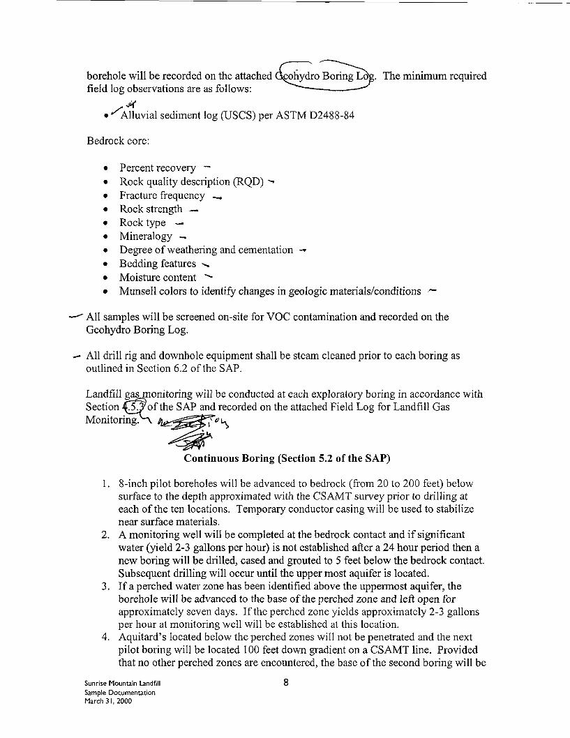
borehole will be recorded on the attached G^phydro Boring Log. The minimum requiredfield log observations are as follows:
S*• "'Alluvial sediment log (USCS) per ASTM D2488-84
Bedrock core:
• Percent recovery —• Rock quality description (RQD) *•*• Fracture frequency —.• Rock strength —.• Rock type —• Mineralogy —• Degree of weathering and cementation -*• Bedding features ->.• Moisture content "-• Munsell colors to identify changes in geologic materials/conditions /~"
" All samples will be screened on-site for VOC contamination and recorded on theGeohydro Boring Log.
All drill rig and downhole equipment shall be steam cleaned prior to each boring asoutlined in Section 6.2 of the SAP.
Landfill gas monitoring will be conducted at each exploratory boring in accordance withSection 5^ of the SAP and recorded on the attached Field Log for Landfill GasMonitoring>\
Continuous Boring (Section 5.2 of the SAP)
1. 8-inch pilot boreholes will be advanced to bedrock (from 20 to 200 feet) belowsurface to the depth approximated with the CSAMT survey prior to drilling ateach of the ten locations. Temporary conductor casing will be used to stabilizenear surface materials.
2. A monitoring well will be completed at the bedrock contact and if significantwater (yield 2-3 gallons per hour) is not established after a 24 hour period then anew boring will be drilled, cased and grouted to 5 feet below the bedrock contact.Subsequent drilling will occur until the upper most aquifer is located.
3. If a perched water zone has been identified above the uppermost aquifer, theborehole will be advanced to the base of the perched zone and left open forapproximately seven days. If the perched zone yields approximately 2-3 gallonsper hour at monitoring well will be established at this location.
4. Aquitard's located below the perched zones will not be penetrated and the nextpilot boring will be located 100 feet down gradient on a CSAMT line. Providedthat no other perched zones are encountered, the base of the second boring will be
Sunrise Mountain Landfill 8Sample DocumentationMarch 31, 2000
advanced to the uppermost aquifer. If another perched zone is encountered thenStep 3 is repeated .
Refusals will be recorded when drilling and sampling through alluvial sediment (utilizingthe split spoon), if rock or highly cemented formations are encountered. If poor recoveryis noted then sampling approaches will be modified to suit the conditions (i.e.conventional coring techniques).
Geophysical tools (prescribed in Section 5.2.3.3,of the SAP) will be utilized to determinethe basic physical characteristics of the alluvium and bedrock. The geophysical tools willbe used in accordance with the manufacturer's recommendations and a record of thefollowing will be logged (based on the lithologic sample logs and downhole conditions):
• Degree of moisture• Clay content• Lithology• Bedding thickness• Diameter of the borehole annulus
A 10 to a maximum 14-inch reaming of the 8-inch pilot hole will be initiated after thegeophysical logging is completed for installation of the well.
Sample Identification
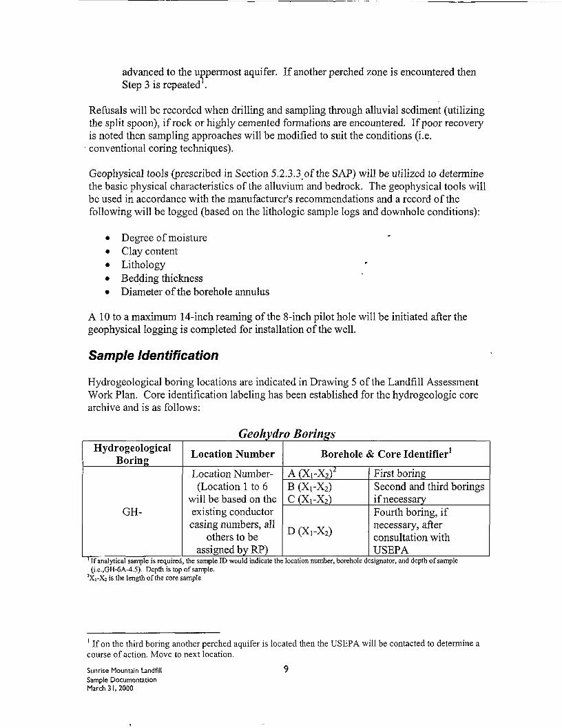
Hydrogeological boring locations are indicated in Drawing 5 of the Landfill AssessmentWork Plan. Core identification labeling has been established for the hydrogeologic corearchive and is as follows:
Geohydro BoringsHydrogeological
Boring
GH-
Location Number
Location Number-(Location 1 to 6
will be based on theexisting conductorcasing numbers, all
others to beassigned by RP)
Borehole & Core Identifier1
A(XrX2)2
B (XrX2)C (X,-X2)
D (X!-X2)
First boringSecond and third boringsif necessaryFourth boring, ifnecessary, afterconsultation withUSEPA
If analytical sample is required, the sample ID would indicate the location number, borehole designator, and depth of sample(i.e.,GH-6A-4.5). Depth is top of sample.
2Xi-X2 is the length of the core sample
1 If on the third boring another perched aquifer is located then the USEPA will be contacted to determine acourse of action. Move to next location.
Sunrise Mountain Landfill 9Sample DocumentationMarch 31, 2000
For example, GH-5A (10-12) represents the core sample from the first boring nearexisting conductor casing 5, from 10 to 12 feet. There are no duplicate samplerequirements for the Geohydro Borings.
The core sample will be placed in a core sample box, labeled as discussed below, and thecore sample will be recorded on the attached Core Storage Record. All core storageboxes will be stored on-site in provided storage units.
Sample labels may be written on the core storage box or may consist of gummed paper ortags. Sample labels for the core boxes used to store the continuous core samples (2-footintervals) shall contain the following information written with a permanent ink marker:
• Sample number and identification• Name of collector• Date and time of collection• Type of Sampler used and percent recovery• Reading from VOC field screening
Sample Handling
Sampling equipment, container requirements, and storage are all outlined in Section 3.3of the SAP. Also, refer to Section 6.7 of the SAP for shipping procedures.
Lagoon Exploratory Drilling
Four lagoons which BLM identified in their CCJM Reconnaissance Investigation Reportof March 18, 1998 will be preliminarily characterized to determine the vertical extent ofcontamination.
Procedure
A qualified, experienced field geologist will monitor all boreholes and drill-operatingprocedures as outlined in subtask 3.4.3.4.2 of the Landfill Assessment Work Plan. Eachborehole will be recorded on the attached Lagoon Boring Log. All samples will bescreened on-site for VOC contamination and recorded on the attached Lagoon BoringLog.
Within each lagoon, two 8-inch boreholes will be drilled. The depths will be based onthe geophysical results that will show the depth to the Tertiary contact. If the geophysicalsurvey results indicate that the Tertiary contact is located at a depth of less than 25 feetbelow ground surface, the boreholes will be completed to the Tertiary contact; otherwise,the boreholes will be completed to a minimum depth of 20 feet below ground surface.
The boreholes will be continuously sampled through the alluvial sediment using a splitspoon sampler. The core from each 2-foot split spoon sampling interval will be logged
Sunrise Mountain Landfill I 0Sample DocumentationMarch 31 , 2000
by the supervising geologist and screened on-site for VOC contamination. The followingwill be recorded on the Lagoon Boring Log:
• Results of the VOC field screening,• Description of the sediment lithologics,• Thickness,• Percentage of recovered core, and• Any observed staining.
The core will be stored in core boxes as discussed below for future reference.
A sample will be selected from every other 2-foot split spoon sampling interval forlaboratory testing (one sample per 4-foot interval). See additional information in WasteSampling of this SOP. If the laboratory test results indicate contamination is present inthe last 4-foot interval of the boring, an additional 10-feet of drilling and sampling will berequired following the same testing procedures. If contamination is found in the last 4-feet of this boring, the process will be repeated until a depth is reached whereby thelaboratory testing results indicate that the sediment is clean or until Tertiary contact isreached. Logging, VOC screening, core sampling and storage as discussed above will beperformed on any additional drilling.
Sample Identification
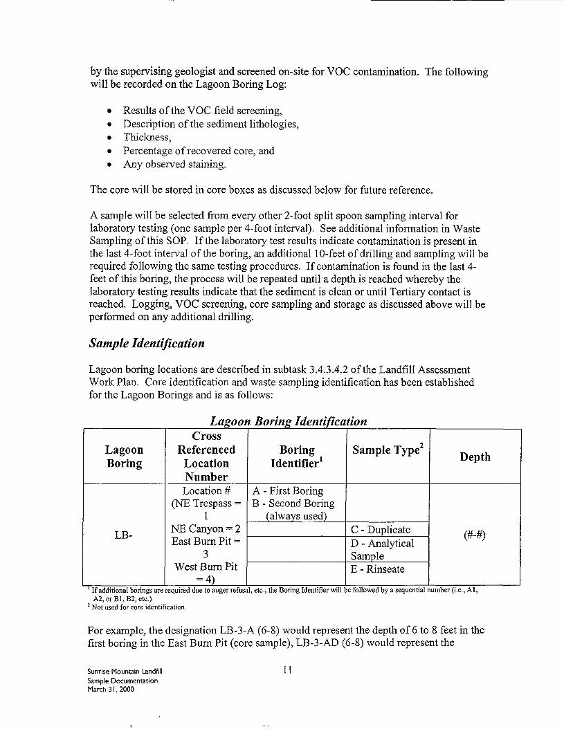
Lagoon boring locations are described in subtask 3.4.3.4.2 of the Landfill AssessmentWork Plan. Core identification and waste sampling identification has been establishedfor the Lagoon Borings and is as follows:
Lagoon Boring Identification
LagoonBoring
LB-
CrossReferenced
LocationNumberLocation #
(NE Trespass =1
NE Canyon = 2East Burn Pit =
3West Bum Pit
= 4)
BoringIdentifier1
A - First BoringB - Second Boring
(always used)
Sample Type2
C - DuplicateD - AnalyticalSampleE - Rinseate
Depth
(#-#)
If additional borings are required due to auger refusal, etc., the Boring Identifier will be followed by a sequential number (i.e., Al,A2,orBl,B2, etc.)
2 Not used for core identification.
For example, the designation LB-3-A (6-8) would represent the depth of 6 to 8 feet in thefirst boring in the East Burn Pit (core sample), LB-3-AD (6-8) would represent the
Sunrise Mountain LandfillSample DocumentationMarch 31, 2000
analytical sample from the same, LB-3-AC (6-8) would represent the duplicate samplefor analytical testing from the same, and LB-3-AE would represent the rinseate samplefor analytical testing from the same (see Waste Sampling section of this SOP). Duplicatesampling for analytical testing and rinseate samples will be done the lesser of once everyten samples or once per day. Duplicate samples and rinseate samples during the LagoonBoring activities are only required when a sample is identified for analytical testing.Core samples do not require a duplicate.
The core sample will be placed in a core sample box, labeled as discussed below, and thecore sample will be recorded on the attached Core Storage Record. All core storageboxes will be stored on-site in provided storage units.
Sample labels may be written on the core storage box or may consist of gummed paper ortags. Sample labels for the core boxes used to store the continuous core samples (2-footintervals) shall contain the following information written with a permanent ink marker:
• Sample number and identification• Name of collector• Date and time of collection• Type of Sampler used and percent recovery• Reading from VOC field screening
See the Waste Sampling section of this SOP for document tracking and labelingrequirements for analytical testing.
Sample Handling
Sampling equipment, container requirements, storage, and sample transportation are alloutlined in Section 3.3 of the SAP. Also, refer to Section 6.7 of the SAP for shippingprocedures. Sample handling requirements for analytical samples are discussed in theWaste Sampling section of this SOP.
Groundwater Sampling
Groundwater sampling requirements are specified in subtask 3.4.5.5.5 of the LandfillAssessment Work Plan.
Procedure
Samples will be collected for laboratory analysis utilizing either a disposable bailer or adecontaminated bladder pump. Samples will be collected in the following order; VOC's,metals, cations and anions general minerals. All bottles for VOC analysis will be filledwith zero headspace. Samples will be collected in laboratory-prepared, pre-cleaned andcertified bottles, containing appropriate preservatives for the specified analysis, following
Sunrise Mountain Landfill 12Sample DocumentationMarch 31, 2000
the procedures outlined in EPA SW-846. Refer to the Landfill Assessment Work Planfor bottle requirements and sample preservatives.
Sample IdentificationEach sample will be designated with a unique number following the table below.
Sunrise Mountain Landfill I 3Sample DocumentationMarch 31, 2000
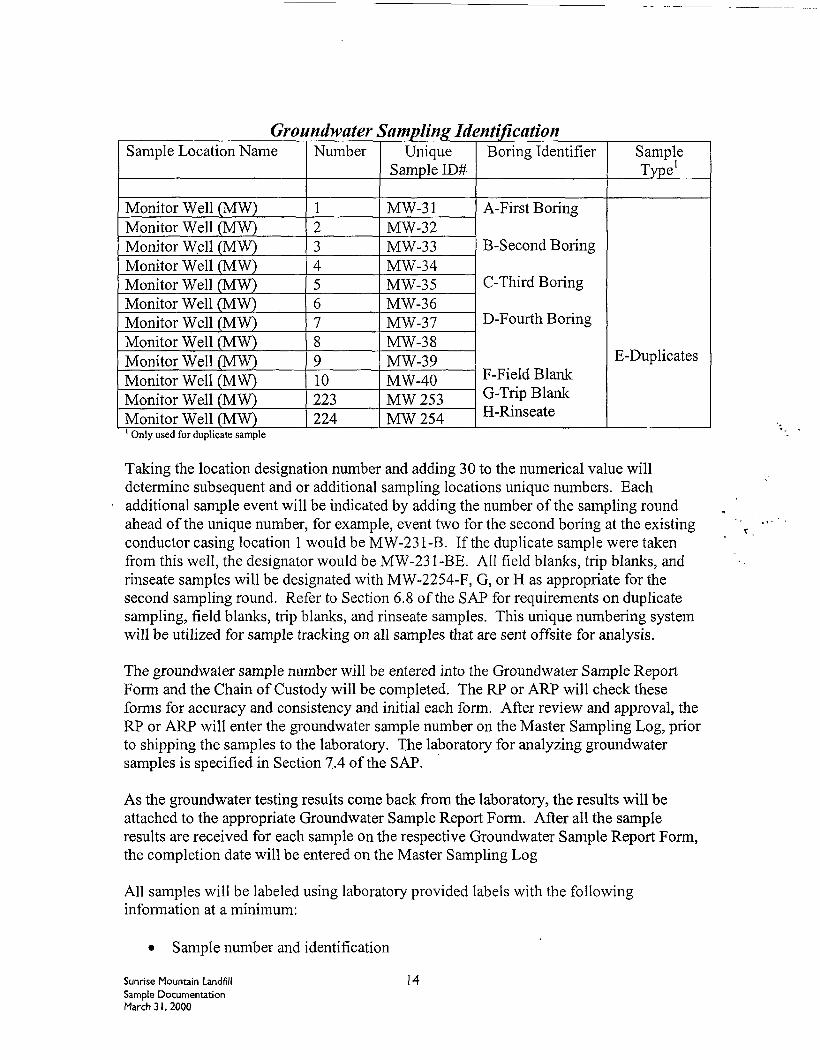
Groundwater Sampling IdentificationSample Location Name
Monitor Well (MW)Monitor Well (MW)Monitor Well (MW)Monitor Well (MW)Monitor Well (MW)Monitor Well (MW)Monitor Well (MW)Monitor Well (MW)Monitor Well (MW)Monitor Well (MW)Monitor Well (MW)Monitor Well (MW)
Number
12345678910223224
UniqueSample ID#
MW-31MW-32MW-33MW-34MW-35MW-36MW-37MW-38MW-39MW-40MW253MW254
Boring Identifier
A-First Boring
B-Second Boring
C-Third Boring
D-Fourth Boring
F-Field BlankG-Trip BlankH-Rinseate
SampleType1
E-Duplicates
1 Only used for duplicate sample
Taking the location designation number and adding 30 to the numerical value willdetermine subsequent and or additional sampling locations unique numbers. Eachadditional sample event will be indicated by adding the number of the sampling roundahead of the unique number, for example, event two for the second boring at the existingconductor casing location 1 would be MW-231-B. If the duplicate sample were takenfrom this well, the designator would be MW-231-BE. All field blanks, trip blanks, andrinseate samples will be designated with MW-2254-F, G, or H as appropriate for thesecond sampling round. Refer to Section 6.8 of the SAP for requirements on duplicatesampling, field blanks, trip blanks, and rinseate samples. This unique numbering systemwill be utilized for sample tracking on all samples that are sent offsite for analysis.
The groundwater sample number will be entered into the Groundwater Sample ReportForm and the Chain of Custody will be completed. The RP or ARP will check theseforms for accuracy and consistency and initial each form. After review and approval, theRP or ARP will enter the groundwater sample number on the Master Sampling Log, priorto shipping the samples to the laboratory. The laboratory for analyzing groundwatersamples is specified in Section 7.4 of the SAP.
As the groundwater testing results come back from the laboratory, the results will beattached to the appropriate Groundwater Sample Report Form. After all the sampleresults are received for each sample on the respective Groundwater Sample Report Form,the completion date will be entered on the Master Sampling Log
All samples will be labeled using laboratory provided labels with the followinginformation at a minimum:
Sample number and identification
Sunrise Mountain LandfillSample DocumentationMarch 31, 2000
14
• Name of collector• Date and time of collection• Place of collection• Type of Sample• Analysis to be performed• Preservatives (if applicable)
Groundwater Sampling Report Form
A groundwater sampling report form will be completed for each well that is sampled.This form will include the following information:
• Date and time of sampling• Site name and project number• Name of sampler
\ • Well number• Total depth of well• Depth to groundwater• Purge volume calculation. PH
\ .V \_ • Conductivity\ * • Temperature
M*' x: • Purge rateV • Purge start/stop time
• Purge equipment• Type of sampling equipment• Analysis required• Number and size of sample containers• Sample attributes• Unique sample number• Actual sample number• Duplicate sample information
Sample Handling
Sampling equipment, container requirements, chain of custody procedures, preservationand storage, and sample transportation are all outlined in Section 3.3 of the SAP. Also,refer to Section 6.7 of the SAP for shipping procedures.
Potable Water Sampling
A water sample will be collected from the initial source of potable water used fordecontamination of sampling devices. The analysis required is the same as required forgroundwater samples. If the source changes, another sample will be obtained.
Sunrise Mountain Landfill I 5Sample DocumentationMarch 3 1, 2000
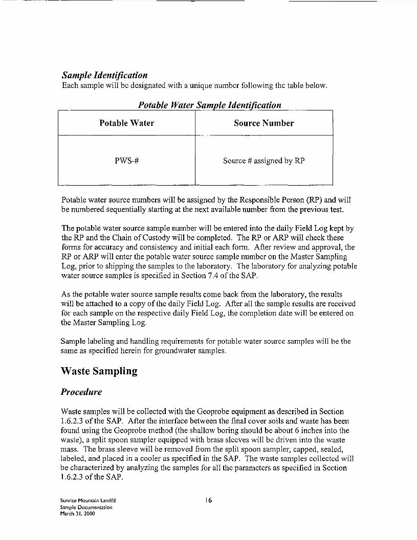
Sample IdentificationEach sample will be designated with a unique number following the table below.
Potable Water Sample Identification
Potable Water Source Number
PWS-# Source # assigned by RP
Potable water source numbers will be assigned by the Responsible Person (RP) and willbe numbered sequentially starting at the next available number from the previous test.
The potable water source sample number will be entered into the daily Field Log kept bythe RP and the Chain of Custody will be completed. The RP or ARP will check theseforms for accuracy and consistency and initial each form. After review and approval, theRP or ARP will enter the potable water source sample number on the Master SamplingLog, prior to shipping the samples to the laboratory. The laboratory for analyzing potablewater source samples is specified in Section 7.4 of the SAP.
As the potable water source sample results come back from the laboratory, the resultswill be attached to a copy of the daily Field Log. After all the sample results are receivedfor each sample on the respective daily Field Log, the completion date will be entered onthe Master Sampling Log.
Sample labeling and handling requirements for potable water source samples will be thesame as specified herein for groundwater samples.
Waste Sampling
Procedure
Waste samples will be collected with the Geoprobe equipment as described in Section1.6.2.3 of the SAP. After the interface between the final cover soils and waste has beenfound using the Geoprobe method (the shallow boring should be about 6 inches into thewaste), a split spoon sampler equipped with brass sleeves will be driven into the wastemass. The brass sleeve will be removed from the split spoon sampler, capped, sealed,labeled, and placed in a cooler as specified in the SAP. The waste samples collected willbe characterized by analyzing the samples for all the parameters as specified in Section1.6.2.3 of the SAP.
Sunrise Mountain Landfill I 6Sample DocumentationMarch 31, 2000
The waste samples will be collected at the same locations that are designated to have alandfill gas sampling probe installed. An additional two shallow borings within each areaspecified below will be taken for the purpose of obtaining a waste sample (no landfill gasprobe installed). Therefore, there will be a total of seven waste samples collected fromthe following areas:
• Area A - Eastern Perimeter Area• Area B - Eastern side of the Lower Southern Flats Area• Area C - Western side of the Lower Southern Flats Area• Area D - Upper deck of the Top Deck Area• Area E - Side-slopes of the Top Deck Area
For Lagoon Borings, a sample will be selected from every other 2-foot split spoonsampling interval for laboratory testing (one sample per 4-foot interval). All samples willbe selected from the finer-grained sediment intervals, and if applicable, from intervalswhere VOCs have been detected and/or staining is present. All selected samples will belaboratory tested for the analytical parameters as specified in Section 1.6.2.3 of the SAP.
Sample Identification
The sample identification system is presented in the Assessment of the Existing FinalCover Soils in this SOP for all waste samples collected from shallow borings. Thesample identification system is presented in the Lagoon Exploratory Drilling section ofthis SOP for all waste samples collected from the Lagoon Borings. Duplicate samplingand rinseate sampling will be done the lesser of every ten samples or once per day.
Duplicate samples during the Shallow Boring activities are only required when a sampleis identified for geotechnical, calcium carbonate analysis, or analytical testing (wastesample). Rinseate samples are only required when a waste sample is obtained during theShallow Boring activities. Core samples do not require a duplicate, but the ManagingGeologist will decide when they are complete based on percent recovery of the core.
Duplicate samples and rinseate samples during the Lagoon Boring activities are onlyrequired when a sample is identified for analytical testing. Core samples do not require aduplicate.
The unique number from the respective sample identification systems referenced abovewill be utilized for sample tracking on all samples that are sent to a laboratory foranalysis. For the shallow boring waste samples, the waste sample number will be enteredinto the Field Log for Geotechnical Sampling and Shallow Boring Observation and theChain of Custody will be completed. For the Lagoon Boring waste samples, the wastesample number will be entered into the Lagoon Boring Log and the Chain of Custodywill be completed. The two waste sample types require separate Chain of Custodies.The RP or ARP will check these forms for accuracy and consistency and initial eachform. After review and approval, the RP or ARP will enter the waste sample number on
Sunrise Mountain Landfill I 7Sample DocumentationMarch 31, 2000
the Master Sampling Log, prior to shipping the samples to the laboratory. The laboratoryfor chemically analyzing soil and waste is specified in Section 7.1 of the SAP.
As the waste sample testing results come back from the laboratory, the results will beattached to the appropriate Field Log for Geotechnical Sampling and Shallow BoringObservation or the Lagoon Boring Log. After all the sample results are received for eachsample on the respective Field Log for Geotechnical Sampling and Shallow BoringObservation or Lagoon Boring Log, the completion date will be entered on the MasterSampling Log
Labels (gummed paper or tags) shall contain the following information:
• Sample number and identification• Name of collector• Date and time of collection• Place of collection• Type of Sample• Analysis to be performed• Preservatives (if applicable)
Sample Handling
Sampling equipment, container requirements, chain of custody procedures, preservation,storage, and sample transportation are all outlined in Section 3.3 of the SAP. Also, referto Section 6.7 of the SAP for shipping procedures.
Landfill Gas Characterization
Procedure
The purpose of this subtask is to characterize the landfill gas. This characterization willconsist of obtaining landfill gas samples from landfill gas sampling probes installed inaccordance with methods described in Section 4.6.1 of the SAP. The landfill gas probeswill be installed concurrently with the work being performed for the shallow borings withsubtask 3.4.3.3 of the Landfill Assessment Work Plan. Landfill gas sampling probes willbe installed in groups of five spaced within an area as follows:
• Area A - Eastern Perimeter Area• Area B - Eastern side of the Lower Southern Flats Area• Area C - Western side of the Lower Southern Flats Area• Area D - Upper deck of the Top Deck Area• Area E - Side-slopes of the Top Deck Area
Sample Identification
Sunrise Mountain Landfill 18Sample DocumentationMarch 31, 2000
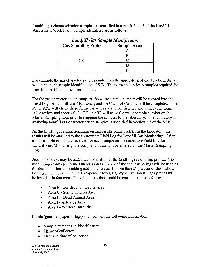
Landfill gas characterization samples are specified in subtask 3.4.4.5 of the LandfillAssessment Work Plan. Sample identifiers are as follows:
Landfill Gas Sample IdentificationGas Sampling Probe
GS-
Sample AreaABCDE
For example the gas characterization sample from the upper deck of the Top Deck Areawould have the sample identification, GS-D. There are no duplicate samples required forLandfill Gas Characterization samples.
For the gas characterization samples, the waste sample number will be entered into theField Log for Landfill Gas Monitoring and the Chain of Custody will be completed. TheRP or ARP will check these forms for accuracy and consistency and initial each form.After review and approval, the RP or ARP will enter the waste sample number on theMaster Sampling Log, prior to shipping the samples to the laboratory. The laboratory foranalyzing landfill gas characterization samples is specified in Section 7.3 of the SAP.
As the landfill gas characterization testing results come back from the laboratory, theresults will be attached to the appropriate Field Log for Landfill Gas Monitoring. Afterall the sample results are received for each sample on the respective Field Log forLandfill Gas Monitoring, the completion date will be entered on the Master SamplingLog.
Additional areas may be added for installation of the landfill gas sampling probes. Gasmonitoring results performed under subtask 3.4.4.4 of the shallow borings will be used asthe decision criteria for adding additional areas. If more than 25-percent of the shallowborings in an area exceed the 1.25-percent level, a group of five landfill gas probes willbe installed in that area. The other areas that would be considered are as follows:
• Area F - Construction Debris Area• Area G - Septic Lagoon Area• Area H - Dead Animal Area• Area I - Asbestos Area• Area J - Western Burn Pits
Labels (gummed paper or tags) shall contain the following information:
• Sample number and identification• Name of collector• Date and time of collection
Sunrise Mountain LandfillSample DocumentationMarch 31, 2000
19
• Place of collection• Type of Sample• Analysis to be performed• Preservatives (if applicable)
Gas samples will be collected using the procedures in Section 4.6.1 of the SAP.
Sample Handling
Sampling equipment, container requirements, chain of custody procedures, preservationand storage, and sample transportation are all outlined in Section 4.6 of the SAP. Also,refer to Section 6.7 of the SAP for shipping procedures.
Field Quality Assurance Samples
For the purpose of this SOP field QA samples shall include: field blanks, trip blanks,duplicate samples, and rinseate samples.
For groundwater sampling, one field blank shall be collected per sampling round. Fieldblanks will be obtained by using distilled water that will be transferred into appropriatecontainers in the field. Field blanks will be handled, labeled, documented and transportedin the same manner as the other groundwater samples. The unique sample number forfield blanks will be as specified in the Groundwater Sampling section of this SOP.
For groundwater sampling, one set of trip blanks will accompany and will be analyzedfor each round of VOC analysis. Trip blanks will consist of VOC sampling containersand should be labeled as specified in the Groundwater Sampling section of this SOP.
For at least one out of every ten samples or once per day, whichever is less; a duplicatesample will be collected. Samples will be obtained, handled, documented andtransported in the same manner as the other like samples. The unique sample number forduplicate samples will be as discussed in the appropriate section of this SOP.
For groundwater sampling, a duplicate sample will be obtained during each day ofsampling groundwater. The duplicate will be obtained at one of the downgradientgroundwater sampling locations to be selected in the field at the time of sampling.
For soil and waste samples, duplicate samples will be collected using the same equipmentand type of containers as is used for original sample collection, utilizing the standardprocedures already provided herein. Care will be taken to keep the composition of boththe original and duplicate samples as similar as possible (i.e., from the same stratigraphiclayer, moisture content, appearance, etc.). The duplicate samples will be identified asspecified herein and will be submitted to the laboratory to be analyzed for the sameparameters and by the same methods, as are the original samples.
Sunrise Mountain Landfill 20Sample DocumentationMarch 31, 2000
If a disposable bailer is used for groundwater sampling, a rinseate sample (consisting ofdeionized water poured into a new (clean) sample bailer and then into sample containers,will be collected during each daily sampling event and analyzed for VOC's. If a bladderpump is used, a rinseate sample will be collected as specified in Section 5.6.2 of the SAP,during each daily sampling event and analyzed for VOC's. The unique sample numberfor a rinseate sample will be as discussed in the Groundwater Sampling section of thisSOP.
For waste samples including Shallow Boring and Lagoon Boring activities, a rinseatesample (consisting of deionized or distilled water poured over the sampling tool after ithas undergone decontamination and been allowed to dry) will be collected in a cleansample jar. A rinseate sample will be collected during each daily sampling event fromeach type of sampling event (i.e., Lagoon Boring or waste sample from Shallow Boring)and analyzed for VOC's at a minimum. The unique sample number for a rinseate samplewill be as discussed in the appropriate section of this SOP.
In addition, at each sample location, one collocated (duplicate) sample may be collected,packaged, labeled, and archived on-site until testing is satisfactorily completed and theEngineering Manager or designee releases the sample(s) for disposal. This shall be doneat the option of the Engineering Manager.
Chain of Custody
Sample numbers on all correspondence and documentation including COC's will beconsistent with the unique numbering system utilized on the individual samplecontainers.
COC's must be initialed by the RP prior to departure from the job site. One copy of theCOC along with the sample report will be maintained by the RP on the jobsite. A sampleis considered within custody if it meets the following criteria:
• If the samples are in a person's actual possession• In view after being in physical possession• Sealed so that no one can tamper with the samples after being in physical
possession• In a controlled area with authorized personnel only• In transit with an approved carrier
The COC form should, at a minimum include:
• Project name and number• Unique sample number• Sample location• Sample matrix• Sampling date and time
Sunrise Mountain Landfill 2 ISample DocumentationMarch 31, 2000
• Preservative• Analysis method• Total number of containers• RP initials• Signatures and date of the sampler and recipient of the samples
Any errors on the COC should be struck through with a single line and initialed by theperson making the correction
Sample Shipment
Samples will be delivered to the laboratory within the specified holding times for therequired analysis as outlined in the SAP. Samples will be accompanied by the COC andreleased to a qualified individual at the laboratory. Samples will be delivered to thelaboratory by field sampling personnel or by laboratory personnel only.
Samples will be packaged according to the following guidelines:
• Labeled and sealed samples will be placed in the cooler with ice or equivalent• A completed COC will be placed inside of the cooler• Cooler will be closed and latched
Custody seals will be placed on the cooler lid to prevent tampering.
Sunrise Mountain Landfill 22Sample DocumentationMarch 31, 2000
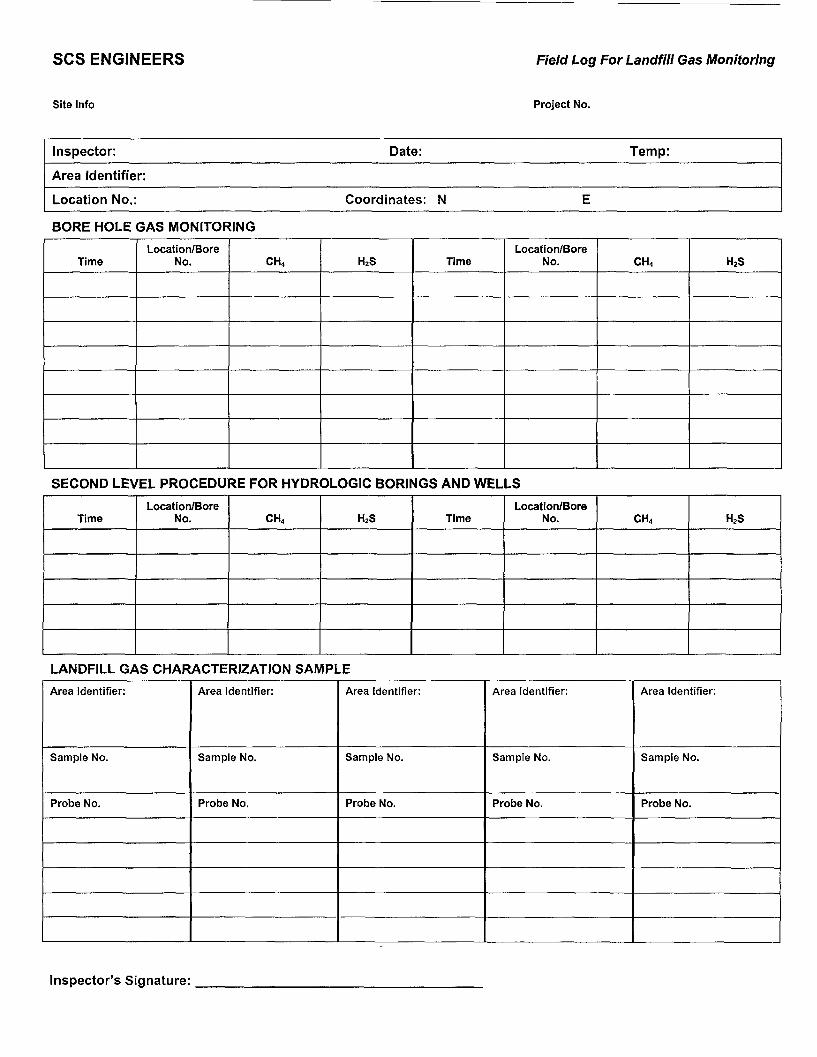
SCS ENGINEERS Field Log For Landfill Gas Monitoring
Site Info Project No.
Inspector: Date: Temp:
Area Identifier:
Location No.: Coordinates: N E
BORE HOLE GAS MONITORING
TimeLocation/Bore
No. CH4 H2S TimeLocation/Bore
No. CH4 HZS
SECOND LEVEL PROCEDURE FOR HYDROLOGIC BORINGS AND WELLS
TimeLocation/Bore
No. CH4 H2S TimeLocation/Bore
No. CH4 H2S
LANDFILL GAS CHARACTERIZATION SAMPLE
Area Identifier:
Sample No.
Probe No.
Area Identifier:
Sample No.
Probe No.
Area Identifier:
Sample No.
Probe No.
Area Identifier:
Sample No.
Probe No.
Area Identifier:
Sample No.
Probe No.
Inspector's Signature:
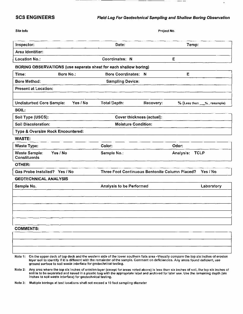
SCS ENGINEERS Field Log For Geotechnical Sampling and Shallow Boring Observation
Site Info Project No.
Inspector: Date: Temp:
Area Identifier:
Location No.: Coordinates: N
BORING OBSERVATIONS (use separate sheet for each shallow boring)
Time: Bore No.:
Bore Method:
Bore Coordinates: N
Sampling Device:
E
Present at Location:
Undisturbed Core Sample: Yes / No Total Depth: Recovery: % (Less than % , resample)
SOIL:
Soil Type (USCS): Cover thickness (actual):
Soil Discoloration: Moisture Condition:
Type & Oversize Rock Encountered:
WASTE:
Waste Type:
Waste Sample: Yes / NoConstituents
Color:
Sample No.:
Odor:
Analysis: TCLP
OTHER:
Gas Probe Installed? Yes / No Three Foot Continuous Bentonite Column Placed? Yes / No
GEOTECHNICAL ANALYSIS
Sample No. Analysis to be Performed Laboratory
COMMENTS:
Note 1: On the upper deck of top deck and the western side of the lower southern flats area -Visually com pare the top six inches of erosionlayer soil to identify if it is different with the remainder of the sample. Comment on deficiencies. Any areas found deficient, useground surface to soil waste interface for geotechnical testing.
Note 2: Any area where the top six inches of erosion layer (except for areas noted above) is less than six inches of soil, the top six inches ofsoil is to be separated and saved in a plastic bag with the appropriate label and archived for later use. Use the remaining depth (sixinches to soil waste interface) for geotechnical testing.
Note 3: Multiple borings at test locations shall not exceed a 10 foot sampling diameter

SCS ENGINEERS Field Log For Geotechnical Sampling and Shallow Boring Observation
Inspector's Signature:
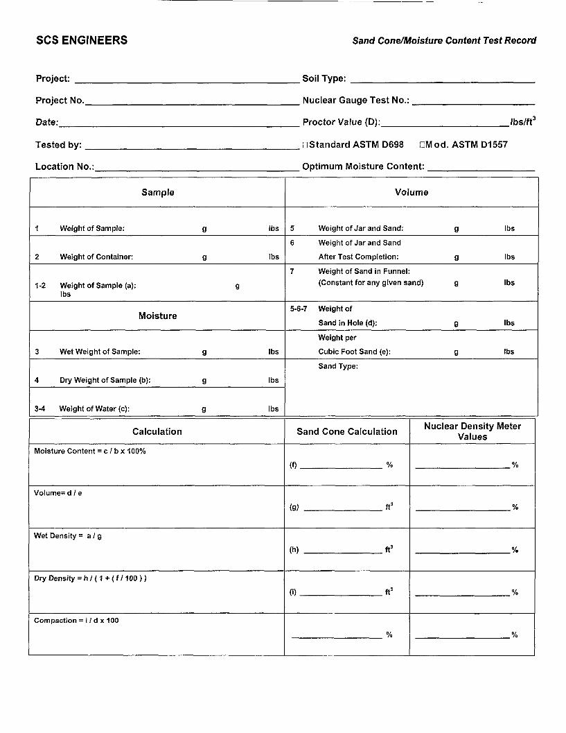
SCS ENGINEERS Sand Cone/Moisture Content Test Record
Project: Soil Type:
Project No..
Date:
Nuclear Gauge Test No.:
Proctor Value (D): Ibs/ft3
Tested by:
Location No.:
.DStandard ASTMD698 DMod. ASTM D1557
Optimum Moisture Content:
Sample
1 Weight of Sample: g Ibs
2 Weight of Container: g Ibs
1-2 Weight of Sample (a): gIbs
Moisture
3 Wet Weight of Sample: g Ibs
4 Dry Weight of Sample (b): g Ibs
3-4 Weight of Water (c): g Ibs
Calculation
Moisture Content = c / b x 100%
Volume=d/e
Wet Density = at g
Dry Density = h / { 1 + ( f / 100 ) )
Compaction = i / d x 100
Volume
5 Weight of Jar and Sand: g Ibs
6 Weight of Jar and Sand
After Test Completion: g Ibs
7 Weight of Sand in Funnel:
(Constant for any given sand) g Ibs
5-6-7 Weight of
Sand in Hole (d): g Ibs
Weight per
Cubic Foot Sand (e): g Ibs
Sand Type:
Sand Cone Calculation
(f) %
(a) ft3
(h) ft3
(i) ft3
%
Nuclear Density MeterValues
%
%
%
%
%

SCS ENGINEERS Sand Cone/Moisture Content Test Record
Reviewed by: Pass/Fail: Date:
Inspector's Signature:
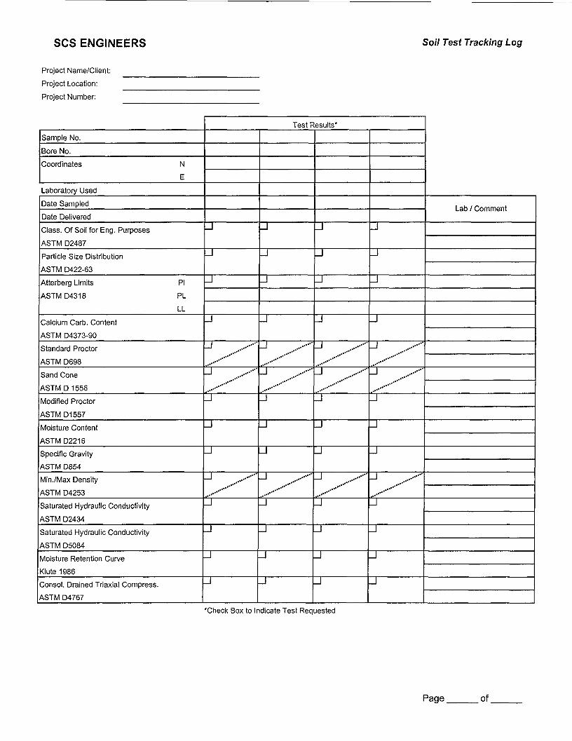
SCS ENGINEERS So/7 Test Tracking Log
Project Name/Client:
Project Location:
Project Number:
Sample No.
Bore No.
Coordinates N
E
Laboratory Used
Date Sampled
Date Delivered
Class. Of Soil for Eng. Purposes
ASTM D2487
Particle Size Distribution
ASTM D422-63
Atterberg Limits PI
ASTMD4318 PL
LL
Calcium Carb. Content
ASTM D4373-90
Standard Proctor
ASTM D698
Sand Cone
ASTM D 1556
Modified Proctor
ASTM D1557
Moisture Content
ASTMD2216
Specific Gravity
ASTM D854
Min./Max Density
ASTM D4253
Saturated Hydraulic Conductivity
ASTM D2434
Saturated Hydraulic Conductivity
ASTM D5084
Moisture Retention Curve
Klute 1986
Consol. Drained Triaxial Compress.
ASTM D4767
Test Results*
J
J
J
J
J ,»•
,.•'*
J
,.*•**"..»•
_J
LJ
LJ
-1
....--•"J
_J
J
J
J
J
J
J
— ' .•••''"''.»•*..»•
J
»•**"*
J
_l
_l
-1...-•••"
,»••
J
J
J
J
J
J
J
J
J .....-•-f,.»"*
J ....•••••'
IJ
LJ
LJ
....•••'J
J
J
J
J
J
J
J
-1 -
,.-•**
-1 i..'"
LJ
U
J
»•»*..•*
J
J
J
J
Lab / Comment
'Check Box to Indicate Test Requested
Page. of
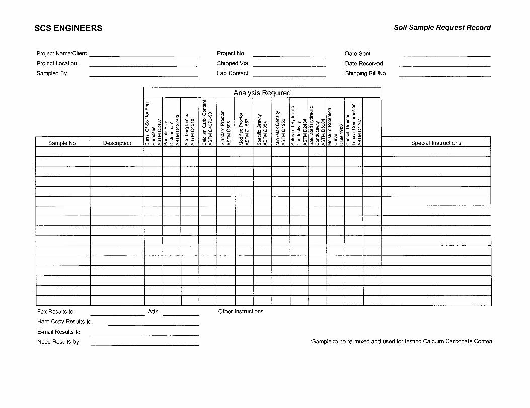
SCS ENGINEERS So/7 Sample Request Record
Project Name/Client
Project Location
Sampled By
Project No
Shipped Via
Lab Contact
Date Sent
Date Received
Shipping Bill No
Sample No Description
Analysis Required
Cla
ss
Of S
oil f
or E
ngP
urpo
ses
AS
TM D
2487
Par
ticle
Siz
eD
istri
butio
n*A
STM
D42
2-63
Atte
rber
g Li
mits
AS
TM D
4318
um C
arb
Con
tent
M D
4373
-90
ra COO < S
tand
ard
Pro
ctor
AS
TM
D69
8
Mod
ified
Pro
ctor
AS
TM
D1
557
Spe
cific
Gra
vity
AS
TM
D85
4
Mm
/M
ax D
ensi
tyA
ST
M D
4253
Sat
urat
ed H
ydra
ulic
Con
duct
ivity
AS
TM D
2434
Sat
urat
ed H
ydra
ulic
Con
duct
ivity
AS
TM D
5084
Moi
stur
e R
eten
tion
Cur
veK
lute
198
6C
onso
l D
rain
edT
naxi
al C
ompr
essi
onA
STM
D47
67
Special Instructions
Fax Results to Attn Other Instructions
Hard Copy Results to.
E-mail Results to
Need Results by 'Sample to be re-mixed and used for testing Calcuim Carbonate Conten