spacewire standard revision draft d issue 1spacewire.esa.int/wg/spacewire/spw-wg-mtg22...spacewire...
TRANSCRIPT

ECSS-E-ST-50-12CRev1 Draft D: November 2014
SpaceWire Standard Revision Draft D Issue 1.0
LIKELY TO CHANGE!

ECSS-E-ST-50-12CRev1 Draft D: November 2014
ECSS-E-ST-50-12C-Rev1 Working Group
Convenor: David Jameux, ESA/ESTEC Editor: Steve Parkes, U. of Dundee Member: Roger Peel, 4Links Ltd Member: Jonas Ekergarn, Aeroflex Gaisler Member: Brice Dellandrea, TAS France Member: Torbjorn Hult, RUAG Sweden Member: Olivier Notebaert, ASD France Member: Ahmed Bouabdallah, U of Rennes (Telecom Bretagne) Member: Fabien Vigeant, CNES Member: Paul Rastetter, ASD Germany
2

ECSS-E-ST-50-12CRev1 Draft D: November 2014
[draft d of revision 1 of the spacewire standard] SpaceWire- Links, nodes, routers and networks
ECSS Secretariat ESA-ESTEC
Requirements & Standards Division Noordwijk, The Netherlands
3

ECSS-E-ST-50-12CRev1 Draft D: November 2014
Foreword
This Standard is one of the series of ECSS Standards intended to be applied together for the management, engineering and product assurance in space projects and applications. ECSS is a cooperative effort of the European Space Agency, national space agencies and European industry associations for the purpose of developing and maintaining common standards. Requirements in this Standard are defined in terms of what shall be accomplished, rather than in terms of how to organize and perform the necessary work. This allows existing organizational structures and methods to be applied where they are effective, and for the structures and methods to evolve as necessary without rewriting the standards.
This Standard has been prepared by the ECSS-E-ST-50-12C-Rev1 Working Group, reviewed by the ECSS Executive Secretariat and approved by the ECSS Technical Authority.
Disclaimer
ECSS does not provide any warranty whatsoever, whether expressed, implied, or statutory, including, but not limited to, any warranty of merchantability or fitness for a particular purpose or any warranty that the contents of the item are error-free. In no respect shall ECSS incur any liability for any damages, including, but not limited to, direct, indirect, special, or consequential damages arising out of, resulting from, or in any way connected to the use of this Standard, whether or not based upon warranty, business agreement, tort, or otherwise; whether or not injury was sustained by persons or property or otherwise; and whether or not loss was sustained from, or arose out of, the results of, the item, or any services that may be provided by ECSS.
Published by: ESA Requirements and Standards Division ESTEC, P.O. Box 299, 2200 AG Noordwijk The Netherlands Copyright: 2014 © by the European Space Agency for the members of ECSS
4

ECSS-E-ST-50-12CRev1 Draft D: November 2014
Change log
Issue Date Details
ECSS‐E‐50‐12A 24 January 2003 First issue.
ECSS‐E‐50‐12B Never issued.
ECSS‐E‐ST‐50‐12C 31 July 2008 Second issue.
Editorial changes to conform with the new ECSS template and reorganization of information in clause 10.
ECSS-E-ST-50-12C Rev1
[expected Q3 2015 after ECSS public review]
Third issue.
Complete rewriting of the standard that aims to be compliant to the previous issues, while making essential improvements and required additions.
General improvement of terms and clauses in line with ECSS rules.
Removal of errors and ambiguities throughout document.
Clarifications of terms and inclusion of more terms in the list of terms.
Improvement to the protocol layering and inclusion of a protocol stack diagram.
Improvement to SpaceWire port architecture diagram.
Improvements to physical level to allow other cable and connector solutions.
Addition of recovery state diagram making the recovery operation clear.
Detailing of multicast operation.
Addition of distributed interrupts.
Addition of UML diagrams and detailed descriptions of node, router, network, broadcast code, unit and device.
Addition of service interface specifications for all layers.
5

ECSS-E-ST-50-12CRev1 Draft D: November 2014
Table of contents
Change log ................................................................................................................. 5
1 Scope ..................................................................................................................... 10
2 Normative references ........................................................................................... 11
3 Terms, definitions and abbreviated terms .......................................................... 13
3.1 Terms from other standards ..................................................................................... 13
3.2 Terms specific to the present standard .................................................................... 13
3.3 Abbreviated terms .................................................................................................... 22
3.4 Conventions ............................................................................................................. 23
4 Principles .............................................................................................................. 24
4.1 SpaceWire purpose .................................................................................................. 24
5 Requirements ........................................................................................................ 25
5.1 Overview .................................................................................................................. 25
5.2 Protocol stack and interface architecture ................................................................. 25
5.2.1 Protocol stack ............................................................................................. 25
5.2.2 Network layer .............................................................................................. 27
5.2.3 Data link layer ............................................................................................. 27
5.2.4 Encoding layer ............................................................................................ 27
5.2.5 Physical layer ............................................................................................. 28
5.2.6 Service interfaces ....................................................................................... 28
5.2.7 SpaceWire port architecture ....................................................................... 28
5.3 Physical layer ........................................................................................................... 29
5.3.1 Cables ........................................................................................................ 30
5.3.2 Connectors ................................................................................................. 32
5.3.3 Cable assemblies ....................................................................................... 34
5.3.4 LVDS PCB tracks ....................................................................................... 38
5.3.5 Line drivers and receivers .......................................................................... 38
5.3.6 Data Strobe skew ....................................................................................... 42
5.4 Encoding layer .......................................................................................................... 43
6

ECSS-E-ST-50-12CRev1 Draft D: November 2014
5.4.1 Serialisation and de-serialisation ................................................................ 43
5.4.2 Character and control code encoding ......................................................... 43
5.4.3 Data signalling rate ..................................................................................... 46
5.4.4 Null detection .............................................................................................. 48
5.4.5 Parity error .................................................................................................. 48
5.4.6 Data strobe encoding and decoding ........................................................... 48
5.4.7 First Null ..................................................................................................... 50
5.4.8 Disconnect .................................................................................................. 50
5.5 Data link layer ........................................................................................................... 50
5.5.1 Data link layer interfaces ............................................................................ 50
5.5.2 Data link layer management parameters .................................................... 51
5.5.3 Sending priority ........................................................................................... 52
5.5.4 Link errors ................................................................................................... 52
5.5.5 Flow control ................................................................................................ 53
5.5.6 Flow control errors ...................................................................................... 54
5.5.7 Link state machine ...................................................................................... 54
5.5.8 Link error recovery ...................................................................................... 60
5.5.9 Accepting broadcast codes for sending ...................................................... 63
5.6 SpaceWire Network .................................................................................................. 63
5.6.1 SpaceWire packets ..................................................................................... 63
5.6.2 Broadcast codes ......................................................................................... 64
5.6.3 SpaceWire nodes ....................................................................................... 75
5.6.4 SpaceWire routers ...................................................................................... 77
5.6.5 SpaceWire network .................................................................................... 83
5.6.6 SpaceWire units and devices ..................................................................... 84
6 Service Interfaces ................................................................................................. 86
6.1 Network layer service interface ................................................................................ 86
6.1.1 Packet service interface ............................................................................. 86
6.1.2 Time-code service interface ....................................................................... 87
6.1.3 Distributed interrupt service interface ......................................................... 88
6.2 Data link layer service interface ............................................................................... 90
6.2.1 N-Char service interface ............................................................................. 90
6.2.2 Broadcast code service interface ............................................................... 91
6.3 Encoding layer service interface .............................................................................. 92
6.3.1 Encoding service interface ......................................................................... 92
6.3.1 Decoding service interface ......................................................................... 93
6.4 Physical layer service interface ................................................................................ 95
7
ECSS-E-ST-50-12CRev1 Draft D: November 2014
6.4.1 Line transmit service interface .................................................................... 95
6.4.1 Line receive service interface ..................................................................... 96
Bibliography ............................................................................................................. 97
Figures Figure 5-1: SpaceWire protocol stack .................................................................................... 26
Figure 5-2: Comparison of SpaceWire layers to ECSS-E-ST-50-12C levels ......................... 26
Figure 5-3: SpaceWire port architecture ................................................................................ 29
Figure 5-4: SpaceWire connector contact identification ......................................................... 34
Figure 5-5: SpaceWire cable assembly type A ...................................................................... 36
Figure 5-6: SpaceWire cable assembly type AL .................................................................... 37
Figure 5-7: LVDS transmitter output signals .......................................................................... 39
Figure 5-8: LVDS transmitter differential output signal ........................................................... 40
Figure 5-9: LVDS receive signal eye pattern mask ................................................................ 41
Figure 5-10: Data character encoding .................................................................................... 44
Figure 5-11: Control character encoding ................................................................................ 45
Figure 5-12: Null control code encoding ................................................................................. 45
Figure 5-13: Broadcast code encoding .................................................................................. 46
Figure 5-14: Parity coverage .................................................................................................. 46
Figure 5-15: Null detection sequence ..................................................................................... 48
Figure 5-16: Data-Strobe (DS) encoding ................................................................................ 49
Figure 5-17: Data and strobe signals for first Null .................................................................. 50
Figure 5-18: Link state machine ............................................................................................. 55
Figure 5-19: Link error recovery state machine ...................................................................... 61
Figure 5-20: Link error recovery process ............................................................................... 63
Figure 5-21: SpaceWire packet format ................................................................................... 64
Figure 5-22: Specialisations and relationships of a SpaceWire broadcast code .................... 65
Figure 5-23 Network layer time-code ..................................................................................... 66
Figure 5-24: Network layer interrupt code .............................................................................. 67
Figure 5-25: Network layer interrupt code and interrupt acknowledge code .......................... 71
Figure 5-26: Network layer extended interrupt code .............................................................. 74
Figure 5-27: Components and specialisations of a SpaceWire node ..................................... 76
Figure 5-28: Components of a SpaceWire routing switch ...................................................... 78
Figure 5-29: Components of a SpaceWire network ............................................................... 84
Figure 5-30: Components and specialisations of a SpaceWire unit ....................................... 85
Figure 5-31: Specialisations of a SpaceWire device .............................................................. 85
8

ECSS-E-ST-50-12CRev1 Draft D: November 2014
Tables Table 5-1: Insertion loss values to be respected for a cable .................................................. 30
Table 5-2: Return loss values to be respected for a cable ..................................................... 31
Table 5-3: Cable PSNEXT specification ................................................................................. 31
Table 5-4: Cable PSELFEXT specification ............................................................................. 31
Table 5-5: Connector contact identification ............................................................................ 33
Table 5-6: Cable assembly type A signal wire connections ................................................... 36
Table 5-7: Cable assembly type AL signal wire connections ................................................. 38
Table 5-8: Address function ................................................................................................... 80
9

ECSS-E-ST-50-12CRev1 Draft D: November 2014
1 Scope
SpaceWire technology has grown from the needs of spacecraft on-board data handling applications. This Standard provides a formal basis for the exploitation of SpaceWire in a wide range of future on-board processing systems.
One of the principal aims of SpaceWire is the support of equipment compatibility and reuse at both the component and subsystem levels. In principle a data-handling system developed for an optical instrument, for example, can be used for a radar instrument by unplugging the optical sensor and plugging in the radar one. Processing units, mass-memory units and down-link telemetry systems developed for one mission can be readily used on another mission, reducing the cost of development, improving reliability and most importantly increasing the amount of scientific work that can be achieved within a limited budget.
Integration and test of complex on-board systems is also supported by SpaceWire with ground support equipment plugging directly into the on-board data-handling system. Monitoring and testing can be carried out with a seamless interface into the on-board system.
SpaceWire is the result of the efforts of many individuals within the European Space Agency, European Space Industry and Academia.
This standard may be tailored for the specific characteristic and constraints of a space project in conformance with ECSS-S-ST-00.
10

ECSS-E-ST-50-12CRev1 Draft D: November 2014
2 Normative references
The following normative documents contain provisions which, through reference in this text, constitute provisions of this ECSS Standard. For dated references, subsequent amendments to, or revision of any of these publications do not apply. However, parties to agreements based on this ECSS Standard are encouraged to investigate the possibility of applying the more recent editions of the normative documents indicated below. For undated references, the latest edition of the publication referred to applies.
ANSI/TIA/EIA-644-A-2001 Electrical Characteristics of Low Voltage Differential Signalling (LVDS) Interface Circuits, Telecommunications Industry Association, January 2001.
ECSS-S-ST-00-01 ECSS system - Glossary of terms
ECSS-E-ST-50-12C Space engineering - SpaceWire - Links, nodes, routers and networks
ECSS-E-ST-50-51C Space engineering - SpaceWire protocol identification
ECSS-E-ST-50-52C Space engineering – Remote Memory Access Protocol
ECSS-Q-ST-70-08 xxx
ECSS-Q-ST-70-26 Xxx
ESCC 3401/029 Connectors, Electrical, Rectangular, Microminiature, based on type MDM, ECSS Detail Specification no. 3401/029, Issue 6, February 2010.
ESCC 3401/071 Connectors, Electrical, Rectangular, Microminiature, Solder Bucket Contacts, with EMI Backshell based on type MDM, ECSS Detail Specification no. 3401/071, Issue 2, March 2010.
ESCC 3401-119 Connectors, Electrical, Rectangular, Nanominiature, Non-Removable Crimp Contacts and Uninsulated Solid Wire Contacts Based On Type Nano-D, Issue TBA.
ESCC 3902 Cables, Coaxial, Radio Frequency, Flexible, ECSS Generic Specification No. 3902, Issue 1 October 2002.
11

ECSS-E-ST-50-12CRev1 Draft D: November 2014
ESCC 3902/003 Cable, “Spacewire”, Round, Quad using Symmetric Cables, Flexible, –200 to +180 °C, Detail Specification no. 3902/003, Issue 3, August 2011.
MIL-DTL-17J Military Specification: Cables, Radio, Frequency, Flexible and Semirigid, General Specification for, 10th February 2014.
12

ECSS-E-ST-50-12CRev1 Draft D: November 2014
3 Terms, definitions and abbreviated terms
3.1 Terms from other standards For the purpose of this Standard, the terms and definitions from ECSS-S-ST-00-01 apply.
3.2 Terms specific to the present standard The UML diagrams of Figure 5-22, Figure 5-27, Figure 5-28, Figure 5-29, Figure 5-30 and Figure 5-31 in clause 5.6 illustrate the relationships between various terms used within this standard.
3.2.1 allocated output port output port that a packet is to be routed through
3.2.2 after 6.4 μs delay of 6.4 μs (nominal) measured from when a state is entered
3.2.3 after 12.8 μs delay of 12.8 μs (nominal) measured from when a state is entered
3.2.4 AutoStart management parameter set by hardware or software which when asserted causes an enabled SpaceWire port to start the SpaceWire link as soon as a Null is received
3.2.5 bit error rate ratio of the number of bits received in error to the total number of bits sent across a link
3.2.6 broadcast code time-code or distributed interrupt code
3.2.7 broadcast code identifier two bit code that identifies the type of broadcast code: 0b00 identifies a time-code and 0b10 identifies a distributed interrupt code
3.2.8 byte eight bits
13

ECSS-E-ST-50-12CRev1 Draft D: November 2014
3.2.9 cargo some information that is to be transferred from a source to a destination which is encapsulated in a packet
3.2.10 character control character or data character
3.2.11 clearing on acknowledgement router router that supports distributed interrupts and clears the bit in the interrupt relay register when an interrupt acknowledgement is received
3.2.12 coding act of translating a set of bits into another set of bits which are more appropriate for transmitting across a medium
3.2.13 configuration port port in a router or node that gives access to a configuration node
3.2.14 configuration node a type of node whose purpose is to configure the router or node that it is part of
3.2.15 control character character that is used to pass control information across a link, i.e. an ESC, FCT, EOP or EEP
3.2.16 control code sequence of an ESC followed by an FCT forming a Null which is used to keep a link active, or a sequence of an ESC character followed by a data character forming a broadcast code which is used to broadcast time-codes and distributed interrupts over a SpaceWire network
3.2.17 control symbol control character encoded in 4-bits for transfer across a link
3.2.18 data character data byte encoded in 10-bits for transfer across a link
3.2.19 data link layer protocol layer which is responsible for the initialisation of a SpaceWire link, for transferring packets and broadcast codes over the link and for recovery from errors on the link
3.2.20 data rate rate at which the application data is transferred across a link
3.2.21 data signalling rate rate at which the bits constituting control and data symbols are transferred across a link
3.2.22 data-strobe sequence of data bits and bit clock encoded into two signals, one containing the data bit sequence (data) and the other changing state whenever the data bit sequence does not (strobe)
14

ECSS-E-ST-50-12CRev1 Draft D: November 2014
3.2.23 data symbol data character encoded in 10-bits
3.2.24 decoding act of translating an encoded set of bits into the original set of bits prior to encoding
3.2.25 de-serialisation transformation of a serial bit stream into a sequence of control or data symbols
3.2.26 destination end point that a packet is being sent to
3.2.27 destination address route to be taken by a packet in moving from source to destination (path address) or an identifier specifying the destination (logical address)
3.2.28 destination node node that is the destination of one or more SpaceWire packets
3.2.29 Disabled management parameter which when asserted prevents a SpaceWire port from operating and which is the inverse of the Enabled condition
3.2.30 disconnect indication from a receiver that there has been no edge on the data or strobe signals for the past 850 ns (nominal) indicating that the link is disconnected
3.2.31 distributed interrupt broadcast code used to distribute interrupts over a SpaceWire network which is either an interrupt code, interrupt acknowledge code, or extended interrupt code
3.2.32 driver electronic circuit that transmits signals across a particular transmission medium
3.2.33 Enabled condition set by hardware or software which when asserted allows a SpaceWire port to operate
3.2.34 encoding layer protocol layer which is responsible for the encoding of characters into symbols, symbol serialisation, data-strobe encoding of the serial bit stream, data-strobe decoding, symbol de-serialisation and decoding of symbols into characters
3.2.35 end of packet marker control character which indicates the end of a packet
3.2.36 end point interface between the network and a host system providing a single port into the network
15

ECSS-E-ST-50-12CRev1 Draft D: November 2014
3.2.37 error recovery scheme method for handling errors detected within a SpaceWire link
3.2.38 ESC control character which is followed by another control character or data character to form a control code
3.2.39 ESC error an invalid ESC sequence, formed from an ESC followed immediately by an EOP, EEP, or ESC
3.2.1 extended interrupt distributed interrupt code used to distribute an interrupt over a SpaceWire network which carries a 6-bit interrupt identifier and is therefore able to support 64 separate interrupts
3.2.2 FIFO port port that has a FIFO interface rather than a SpaceWire interface
3.2.3 first Null initial Null received without a parity error when the link state machine is not in the ErrorReset state
3.2.4 flow control token (FCT) control character used to manage the flow of data across a link, each flow control token being exchanged for eight N-Chars
3.2.5 gotBC sometime after the first Null was received (i.e. when gotNull is asserted) a broadcast code has been received without a parity error
3.2.6 gotFCT sometime after the first Null was received (i.e. when gotNull is asserted) an FCT has been received without a parity error
3.2.7 gotNchar sometime after the first Null was received (i.e. when gotNull is asserted) an N-Char has been received without a parity error
3.2.8 gotNull Null has been received without a parity error
3.2.9 group adaptive routing the assignment of a set of several ports to a logical or path address so that when a packet arrives with that address it is switched to one of the set of several ports that is currently available to accept the packet or that becomes available first
3.2.10 host interface interface to a host system
3.2.11 host system system that is connected to a SpaceWire network via an end point and which uses the services of that SpaceWire network
16

ECSS-E-ST-50-12CRev1 Draft D: November 2014
3.2.12 input port receive side of a port
3.2.13 interrupt acknowledgement code distributed interrupt code used to confirm that an interrupt has reached the appropriate interrupt handler and which carries a 5-bit interrupt identifier
interrupt code with bit 5 set to 1, which is used to confirm that a distributed interrupt has reached the appropriate interrupt handler
3.2.14 interrupt code distributed interrupt code used to distribute an interrupt over a SpaceWire network and which carries a 5-bit interrupt identifier
3.2.15 interrupt destination node that a distributed interrupt is to be received and handled by
3.2.16 interrupt handler node that is responsible for handling an interrupt code with a specific value interrupt identifier
3.2.17 interrupt identifier value which is held in the value field of an distributed interrupt code and which identifies the particular interrupt being carried by the distributed interrupt code and which has a 5-bit value for interrupt codes and interrupt acknowledge codes and a 6-bit value for extended interrupt codes
5-bit value representing one of 32 possible interrupts or in extended interrupt mode a 6-bit value representing one of 64 interrupts, which is held in the value field of an interrupt code and which identifies the particular interrupt being carried by the interrupt code
3.2.18 interrupt register register in a node or router that holds the current state of the distributed interrupt where the ith bit of the register relates to the interrupt identifier of value i
3.2.19 interrupt relay register interrupt register in a router used to prevent repeated circular propagation of interrupt codes
3.2.20 interrupt flag interrupt flag in an end point which is set to Active when a corresponding interrupt arrives and cleared to Ready when the host system has serviced the interrupt
3.2.21 interrupt source node that generates a distributed interrupt
3.2.22 jitter random errors in the timing of a signal
3.2.23 L-Char link character
17

ECSS-E-ST-50-12CRev1 Draft D: November 2014
3.2.24 leading data character very first data character sent over a link after initialisation or the first data character following the EOP or EEP that terminated the previous packet
3.2.25 line driver electronic circuit that drives signals across a particular transmission medium
3.2.26 line receiver electronic circuit that receives signals sent across a particular transmission medium
3.2.27 link bi-directional connection between two ports used to transfer packets and broadcast codes between the two ports
3.2.28 link character a control character or control code which appears on the link only and is not passed between the data link and network layers, i.e. an FCT or Null
3.2.29 link error a disconnect error, parity error, ESC error or credit error
3.2.30 link interface port
3.2.31 link receiver receiver at an end of a SpaceWire link
3.2.32 LinkStart management parameter set by hardware or software which when asserted causes an enabled SpaceWire port to attempt to start the SpaceWire link by sending Nulls
3.2.33 link transmitter transmitter at an end of a SpaceWire link
3.2.34 logical address data character which identifies the destination for the packet
3.2.35 low voltage differential signalling particular form of differential signalling using low voltage signals
3.2.36 management parameter configuration parameter, control variable or status variable of a SpaceWire node or router used to manage its operation
3.2.37 multicast the sending of the same packet from a source to two or more destinations or the sending of the same packet through two or more output ports of a router concurrently
18

ECSS-E-ST-50-12CRev1 Draft D: November 2014
3.2.38 multicast set set of output ports assigned to a logical address through which a packet with that logical address will be forwarded concurrently
3.2.39 N-Char normal character
3.2.40 network two or more nodes connected together via one or more links and zero or more routing switches
NOTE A point-to-point link between two nodes is therefore regarded as a network.
3.2.41 network level protocol level responsible for transferring packets across a SpaceWire network from source node to destination node via links and routers
3.2.42 node source or destination of SpaceWire packets comprising one or more endpoints each providing an interface between a port and a host system
3.2.43 normal character data character, EOP or EEP
3.2.44 Null control code made up of an ESC followed by an FCT which is sent to keep the data link active when there are no data or control characters to send, thus preventing a disconnect
3.2.45 output port transmit side of a port
3.2.46 packet sequence of normal-characters comprising a destination address, cargo and an end of packet marker
3.2.47 path address series of one or more data characters at the start of a packet which define the route to be taken across a SpaceWire network from source to destination
3.2.48 physical layer protocol layer which specifies the cables, connectors, cable assemblies, line drivers and line receivers
3.2.49 port SpaceWire interface or FIFO interface comprising an input port and an output port
3.2.50 PSSELFEXT xxx
3.2.51 PSNEXT xxx
19

ECSS-E-ST-50-12CRev1 Draft D: November 2014
3.2.52 receive error error detected when receiving a symbol, i.e. a parity error
3.2.53 receive FIFO FIFO memory which stores received N-Chars until they can be read by the application via the SpaceWire port interface
3.2.54 receiver circuit that receives signals from the line receiver and decodes those signals into a stream of characters
3.2.55 reset power on reset, other hardware reset or software commanded reset
3.2.56 router routing switch
NOTE The term “router” is used because of the heritage of SpaceWire which is based on IEEE1355-1995 which is in turn based on earlier work on Transputer technology. This work predated the Internet and the use of the term “router” to mean a device that determines the route to a required destination as opposed to a “switch” that switches a packet to an output port based on an address. In SpaceWire the term “router” is used to mean a routing switch or switch that directs a packet to an output port based on a destination address and a routing table. This is widely understood terminology in the SpaceWire community.
3.2.57 routing switch switch with one or more ports, a switch matrix, a configuration port and a local broadcast code register, which optionally broadcasts broadcast codes and which switches packets from one port to another where the destination address of each packet is used by the switch to determine which port the packet is forwarded through
3.2.58 routing table table in a router that is used to look-up the output port a packet is to be sent through using the leading data character of the packet as an index into that table
3.2.59 serialisation transformation of a sequence of control or data symbols into a serial bit stream
3.2.60 signal measurable quantity that varies with time and propagates along a transmission medium to transfer information across that medium
3.2.61 skew difference in time between the expected position of the rising or falling edge of a signal and the actual position of that signal
20

ECSS-E-ST-50-12CRev1 Draft D: November 2014
3.2.62 source originator of a packet, signal or other form of information
3.2.63 source node node that is the source of one or more SpaceWire packets
3.2.64 SpaceWire interface interface comprising a transmitter for sending information across a SpaceWire link, and a receiver for receiving information from that SpaceWire link
3.2.65 SpaceWire port port which has a SpaceWire interface
3.2.66 switch matrix non-blocking, worm-hole routing switch that switches a packet arriving at an input port of a router to the appropriate output port
3.2.67 symbol encoded data character, encoded control character or encoded control code
3.2.68 time-code control-code comprising ESC followed by a single data character holding six bits of information and two broadcast code identification bits set to 0b00, which is used to distribute synchronisation information over a SpaceWire network
3.2.69 time-code master node that is responsible for periodically sending out time-codes which are broadcast across the SpaceWire network
3.2.70 time-code register register in a node or router that holds the value of the last time-code received
3.2.71 time-code value six-bits of information contained in a time-code
3.2.72 transmission medium medium over which data is transferred e.g. screened twisted-pair wires
3.2.73 transmit FIFO a FIFO memory which stores N-Chars until they can be sent across the link.
3.2.74 transmitter circuit that encodes the characters that are to be sent across a link, serialises them, data-strobe encodes them and passes the resulting data and strobe signals to line drivers for transmission across the physical medium
3.2.75 unit an entity, like an instrument, processor or mass memory, which contains zero or more nodes and zero or more routing switches and which contains at least one node or one routing switch
21

ECSS-E-ST-50-12CRev1 Draft D: November 2014
3.3 Abbreviated terms The following abbreviations are defined and used within this standard:
Abbreviation Meaning
AWG American wire gauge
BC broadcast code
BER bit error rate
D data
DC direct current
DS Data-Strobe
ECSS European Cooperation for Space Standardization
EEP error end of packet
EOP end of packet
ESA European Space Agency
ESC escape character
ESCC European Space Components Coordination
FCT flow control token
FIFO first in first out
ID identifier
IID Interrupt identifier
L-Char link character
LS least-significant
LSB least significant bit
LVDS low voltage differential signalling
LVTTL low voltage transistor-transistor logic
Mb/s Megabits per second
Mbps Megabits per second
MS most-significant
MSB most-significant bit
N-Char normal-character
PCB printed circuit board
PSELFEXT xxx
PSNEXT xxx
RX receive
S strobe
SerDes serialiser/de-serialiser
22

ECSS-E-ST-50-12CRev1 Draft D: November 2014
SpW SpaceWire
TDR time domain reflectometer
TX transmit
UML Unified Modelling Language
3.4 Conventions In this document hexadecimal numbers are written with the prefix 0x, for example 0x34 and 0xDF15.
Binary numbers are written with the prefix 0b, for example 0b01001100 and 0b01.
Decimal numbers have no prefix.
23

ECSS-E-ST-50-12CRev1 Draft D: November 2014
4 Principles
4.1 SpaceWire purpose To be written…
24

ECSS-E-ST-50-12CRev1 Draft D: November 2014
5 Requirements
5.1 Overview This section provides the normative requirements for SpaceWire. It is separated into several functional layers.
• Section 5.1 is a short overview of the following sub-sections.
• Section 5.2 describes the SpaceWire protocol stack and architecture of a SpaceWire port.
• Section 5.3 specifies the physical layer of SpaceWire which covers the specification of the cables, connectors, cable assemblies, line drivers and line receivers.
• Section 5.4 specifies the encoding layer which covers the encoding of characters into symbols, symbol serialisation, data-strobe encoding of the serial bit stream, data-strobe decoding, symbol de-serialisation and decoding of symbols into characters.
• Section 5.5 specifies the data link layer of SpaceWire which is responsible for transferring packets and broadcast codes over a link, initialising the SpaceWire link, and managing the recovery from errors on the link.
• Section 5.6 describes the network layer which covers SpaceWire packets, nodes, routing switches, networks, time-code broadcasting and distributed interrupt operation.
5.2 Protocol stack and interface architecture In this section the SpaceWire protocol stack is specified along with the service access points of the various layers and the architecture of a SpaceWire interface.
5.2.1 Protocol stack a. The SpaceWire protocol stack shall be layered as illustrated in Figure 5-1.
25

ECSS-E-ST-50-12CRev1 Draft D: November 2014
Physical Layer
User Application
Encoding Layer
Data Link Layer
Network Layer
N-Chars BroadcastCodes
Data-Strobe TX
Driver/ReceiverCablesConnectors
Link state machineLink error recovery
NodesRouters and routingTime-codesInterruptsPacket definition
Packets Time-codes Interrupts
TXChars
Encoding of charactersSerDesData-Strobe Encoding
Data-Strobe RX
RXChars
TXEnable
gotNull ParityError Disconnect
Figure 5-1: SpaceWire protocol stack
NOTE A comparison of the levels in the ECSS-E-ST-50-12C to the layers of this current standard is provided in Figure 5-2.
PhysicalLayer
Data LinkLayer
NetworkLayer
Physical Level
User ApplicationUser Application
Signal Level
Character Level
Exchange Level
Packet Level
Network Level
N-Chars BroadcastCodes
Symbols
Driver/Receiver
CablesConnectors
Link state machineLink error recovery
NodesRouters and routingTime-codes
Packet definition
Packets Time-codes Interrupts
Characters
EncodingLayer
Encoding of characters
SerDesData-Strobe Encoding
Figure 5-2: Comparison of SpaceWire layers to ECSS-E-ST-50-12C levels
26

ECSS-E-ST-50-12CRev1 Draft D: November 2014
5.2.2 Network layer a. The SpaceWire network layer shall provide three principal services:
1. A packet service which shall send and receive packets over a SpaceWire network.
2. A time-code service which shall send and receive time-codes over a SpaceWire network.
3. A distributed interrupt service which shall send and receive distributed interrupts over a SpaceWire network.
b. A SpaceWire implementation shall support the packet service, optionally support the time-code service and optionally support the distributed interrupt service.
c. The SpaceWire network layer shall accept service requests from user applications.
d. The SpaceWire network layer shall be responsible for transferring SpaceWire packets, time-codes and distributed interrupts over a SpaceWire network.
e. The SpaceWire network layer shall use the services of the SpaceWire data link layer.
5.2.3 Data link layer a. The SpaceWire data link layer shall provide two services:
1. An N-Char service which shall send and receive N-Chars (the components of packets) over a SpaceWire link.
2. A broadcast code service which shall send and receive broadcast codes (time-codes and distributed interrupt codes) over a SpaceWire link.
b. The data link layer shall accept service requests from the network layer.
c. The data link layer shall be responsible for establishing communications across the SpaceWire link, for managing the flow of information over the link, for sending and receiving N-Chars, for sending and receiving broadcast codes and for re-establishing communications across the link after errors that occur over the link.
d. The data link layer shall use the services of the SpaceWire encoding layer.
5.2.4 Encoding layer a. The SpaceWire encoding layer shall provide two services:
1. A character encoding service which shall encode characters into symbols, serialise those symbols and data-strobe encode them ready for transmission over the SpaceWire physical layer.
2. A character decoding service which shall recover the data bit stream from the data-strobe signals received from the physical
27

ECSS-E-ST-50-12CRev1 Draft D: November 2014
layer, de-serialise that bit-stream, and decode the resulting symbols into characters.
b. The encoding layer shall accept service requests from the SpaceWire data link layer.
c. The encoding layer shall be responsible for encoding and decoding of characters into a form suitable for sending over the SpaceWire physical layer.
d. The encoding layer shall use the services of the SpaceWire physical layer.
5.2.5 Physical layer a. The SpaceWire physical layer shall provide two services:
1. A transmit service which transmits the data and strobe signals from the encoding layer over the physical medium.
2. A receive service which receives the data and strobe signals from the physical medium and passes them to the encoding layer.
b. The SpaceWire physical layer shall accept service requests from the encoding layer.
c. The SpaceWire physical layer shall be responsible for transmitting and receiving the data and strobe signals over PCB tracks, connectors and cable assemblies.
5.2.6 Service interfaces The service interfaces for each layer of the SpaceWire protocol stack are detailed in section 6.
5.2.7 SpaceWire port architecture a. A SpaceWire port shall comprise:
1. A SpaceWire port interface which shall include a packet transmit interface, a packet receive interface, a broadcast code transmit interface and a broadcast code receive interface.
2. A transmit FIFO (TX FIFO) which shall store N-Chars provided by the application via the SpaceWire port interface until they can be sent across the link.
3. A receive FIFO (RX FIFO) which shall store received N-Chars until they can be read by the application via the SpaceWire port interface.
4. A flow control manager which shall manage the flow of data over the link preventing data from being sent when there is no space for it in the receive FIFO.
5. A link state machine which shall be responsible for controlling the starting of a link and its recovery from errors.
28

ECSS-E-ST-50-12CRev1 Draft D: November 2014
6. A transmitter which shall be responsible for encoding the characters to be sent over the link into symbols, serialising those symbols into a bit stream and encoding the bit stream into a data and strobe pair of signals.
7. A receiver which shall be responsible for decoding the received data and strobe pair of signals into a data bit stream, de-serialising that bit stream into symbols and decoding the received symbols into characters.
8. A pair of line drivers which shall convert the data and strobe signals into LVDS signals for driving across the link.
9. A pair of line receivers which shall receive the LVDS signals and recover the data and strobe signals that were driven across the link.
NOTE The SpaceWire port architecture is illustrated in Figure 5-3.
Flow ControlManager
TX FIFO
RX FIFO
Link StateMachine
TX RX
N-CharTX
N-CharRX
Broadcast-codeRX
Broadcast-codeTX
Data Link Layer
Encoding Layer
Physical LayerLine Drivers Line Receivers
Connnector
Figure 5-3: SpaceWire port architecture
5.3 Physical layer The physical layer specifies the line drivers and receivers for transmitting and receiving the SpaceWire data and strobe signals over the physical medium, and specifies the cables, connectors, cable assemblies and PCB tracks that make up that physical medium.
29

ECSS-E-ST-50-12CRev1 Draft D: November 2014
5.3.1 Cables
5.3.1.1 Cable construction a. The SpaceWire cable shall carry four differential signals.
b. The SpaceWire cable shall comprise four screened twisted-pairs with an overall shield constructed according to ESCC 3902/003.
NOTE ECSS 3902/003 describes several variants of the SpaceWire cable to suit a range of spacecraft on-board applications.
c. Other forms of cable construction may be used provided that the cable characteristics fulfil the requirements in clauses 5.3.1.2 to 5.3.1.7.
NOTE This is to permit special forms of cable construction for specific applications.
5.3.1.2 Differential characteristic impedance a. The characteristic impedance of each differential signal pair shall be
100 ± 6 Ω.
b. The characteristic impedance of each differential signal pair shall be verified according to MIL-DTL-17J, Para. 4.8.7, using a time domain reflectometer (TDR) with a rise time of 150 ps or less.
5.3.1.3 Skew a. The intra-pair skew of each differential signal pair shall be less than 0.05
ns/m.
b. The inter-pairs skew for the complete cable shall be less than 0.1 ns/m.
5.3.1.4 Insertion loss a. The sinusoidal signal loss through the unloaded balanced cable shall be
according to the values provided in Table 5-1.
Table 5-1: Insertion loss values to be respected for a cable
Data rate Frequency
(3rd harmonic)
Insertion loss
10 Mbps 15 MHz ≤ 0.27 dB/m
100 Mbps 150 MHz ≤ 0.45 dB/m
200 Mbps 300 MHz ≤ 0.65 dB/m
400 Mbps 600 MHz ≤ 0.94 dB/m
NOTE The attenuation values in the table concern the cable only and do not take into account the additional losses due to the connectors of a SpaceWire cable assembly.
30

ECSS-E-ST-50-12CRev1 Draft D: November 2014
5.3.1.5 Return loss a. The cable return loss through the unloaded balanced cable shall be
according to the values provided in Table 5-2.
Table 5-2: Return loss values to be respected for a cable
Data rate Frequency
(3rd harmonic)
Return loss
10 Mbps 15 MHz ≤ 2 dB/m
100 Mbps 150 MHz ≤ 1.9 dB/m
200 Mbps 300 MHz ≤ 1.5 dB/m
400 Mbps 600 MHz ≤ 1.2 dB/m
NOTE The attenuation values in the table concern the cable only and do not take into account the additional losses due to the connectors of a SpaceWire cable assembly.
5.3.1.6 PSNEXT and PSELFEXT a. The spacewire cable shall conform to the PSNEXT and PSELFEXT values
in Table 5-3 and Table 5-4 respectively.
Table 5-3: Cable PSNEXT specification
Frequency (MHz) PSNEXT (dB)
100 73.0
500 63.5
1000 39.0
Table 5-4: Cable PSELFEXT specification
Frequency (MHz) PSELFEXT (dB)
100 65.0
500 50.5
1000 41.5
NOTE The length of cable from which values have been derived is 5.18m
5.3.1.7 Inter-pair crosstalk a. The differential crosstalk between any two pairs in the SpaceWire cable
shall be less than -50 dB/m up to 1 GHz. the minimum delay between any two edges (being data -> strobe, strobe -> data, data -> data or strobe -> strobe) measured at the zero crossing point. This delay is 3 ns in the SpW-10X, it is 2,5 ns in the draft GR718 data sheet I have and we have achieved just below 2 ns in the Atmel ATC18 process.the minimum delay between any two edges (being data -> strobe, strobe -> data, data -> data or strobe -> strobe) measured at the
31

ECSS-E-ST-50-12CRev1 Draft D: November 2014
zero crossing point. This delay is 3 ns in the SpW-10X, it is 2,5 ns in the draft GR718 data sheet I have and we have achieved just below 2 ns in the Atmel ATC18 process.
5.3.2 Connectors
5.3.2.1 General a. The connectors for the SpaceWire cable assembly shall be either Type A,
or Type B.
b. The Type A SpaceWire connector shall be a micro-miniature D-type connector with nine crimp or solder contacts, as defined in ESCC 3401/029 and ESCC 3401/071.
c. The Type B SpaceWire connector shall be any type connector with the following characteristics:
1. Contacts pairs with differential impedance of 100 ± 6 Ω.
2. Compatible with ESCC 3902/003 cables or ESCC 3902/002.
3. Compatible with the space environment as defined in ESCC 3401.
5.3.2.2 Receptacles a. Receptacles shall be used on circuit boards and unit assemblies to which
SpaceWire cables are to be attached.
b. Receptacles shall be equipped with female contacts.
c. The SpaceWire conductors shall be directly soldered or crimped to the contacts.
d. Soldering of conductors to contacts shall conform to ECSS-Q-ST-70-08.
e. Crimping of conductors to contacts shall conform to ECSS-Q-ST-70-26.
f. The signal transfer impedance between a mated plug and receptacle shall be:
1. Less than 10 mΩ at DC.
2. Less than TBD Ω at 200 MHz.
g. The body of the receptacle shall be connected to the board or unit chassis with a low broadband impedance connection.
h. The signal transfer impedance between the body of the receptacle and unit ground should be:
1. Less than 10 mΩ at DC.
2. Less than TBD Ω at 200 MHz.
i. The receptacle should include a conductive gasket for EMI improvement.
j. Receptacles with flying leads should be used for connection to a PCB.
32
ECSS-E-ST-50-12CRev1 Draft D: November 2014
NOTE This is to improve robustness against mechanical shock and vibration compared to PCB mounting connectors.
5.3.2.3 Plugs a. Plugs shall be used on cable assemblies.
b. Plugs shall be equipped with male contacts.
c. The SpaceWire conductors shall be directly soldered or crimped to the contacts.
d. Soldering shall conform to ECSS-Q-ST-70-08.
e. Crimping shall conform to ECSS-Q-ST-70-26.
f. The shield of the SpaceWire cable shall be circularly terminated to the connector body via an EMI backshell.
g. The signal transfer impedance between the shield of the SpaceWire cable and the body of the plug shall be:
1. Less than 10 mΩ at DC.
5.3.2.4 Connector contact identification
5.3.2.4.1 Type A connector
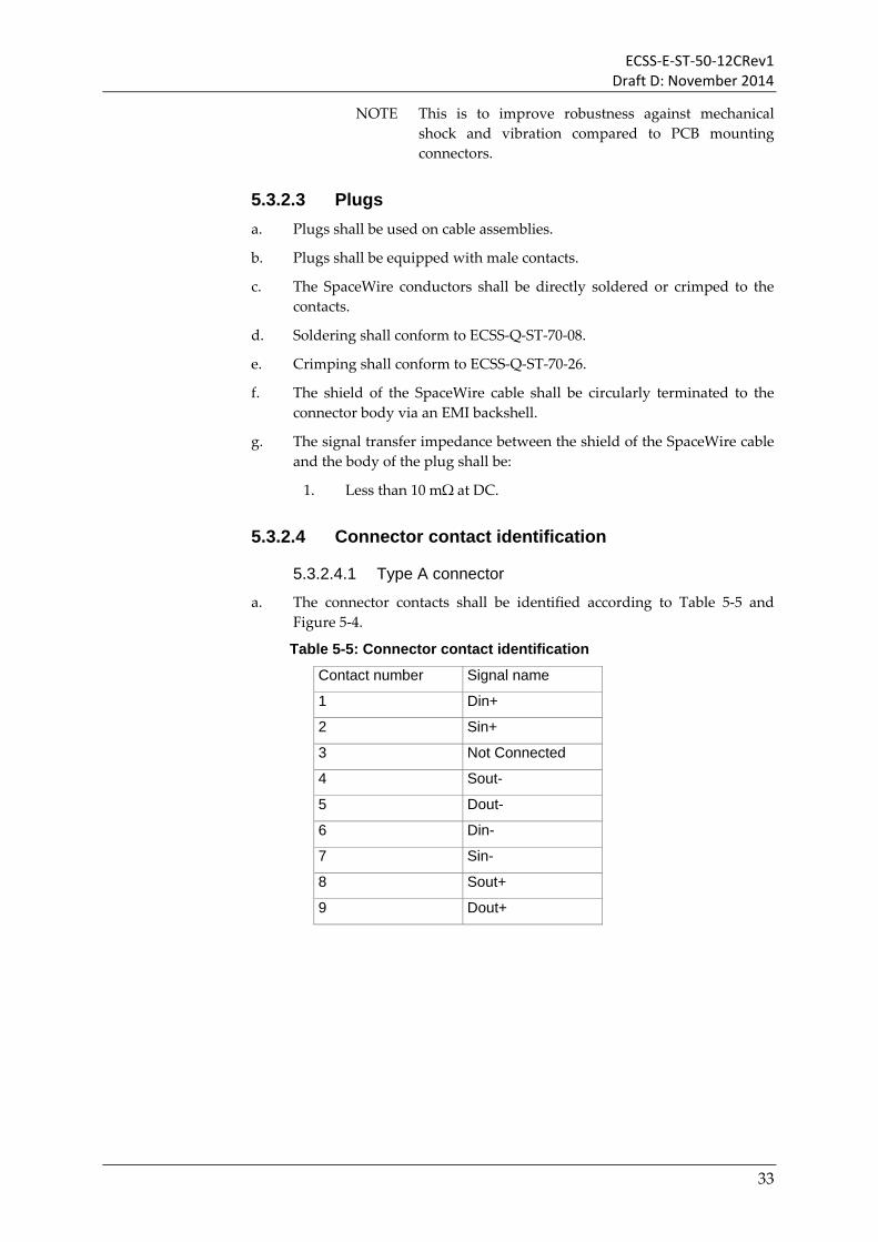
a. The connector contacts shall be identified according to Table 5-5 and Figure 5-4.
Table 5-5: Connector contact identification
Contact number Signal name
1 Din+
2 Sin+
3 Not Connected
4 Sout-
5 Dout-
6 Din-
7 Sin-
8 Sout+
9 Dout+
33

ECSS-E-ST-50-12CRev1 Draft D: November 2014
Dout+
Dout-Sin+
Sin- Sout+
Sout-Din+
Din-
NotConnected
1 52 43
6 87 9
Viewed from rear of receptacle or front of plug
Figure 5-4: SpaceWire connector contact identification
5.3.2.5 PCB mounting connector a. Flying lead connectors should be used for connection to a PCB.
b. Flying lead connectors used for connection to a PCB should have all the leads cropped to the same short length (less than 25 mm) and the wires comprising the differential signal pairs be twisted together.
NOTE This helps to minimize the discontinuity in impedance caused by the connector.
c. PCB mounting right-angled connectors should not be used.
d. If a PCB mounting is used where one of the differential signal paths (e.g. D+) in the connector is longer than that of the related differential signal path (e.g. D-), track length compensation shall be performed at the connector end of the PCB tracks to maintain the differential signal across the PCB.
NOTE The reason for this is that in a right angle connector the topmost row of pins on the right-angled connector has longer leads than the bottom row.
5.3.3 Cable assemblies
5.3.3.1 Overview a. Cable assemblies shall consist of two identical plug connectors, joined by
a length of cable.
5.3.3.2 Cable length and electrical performance a. The maximum length of the cable assembly shall be determined by data
to strobe skew, jitter, and signal attenuation.
NOTE The maximum length depends on the choice of the cable. For shorter length and when small bend radii are required, flexible cable can be used as long as the
34

ECSS-E-ST-50-12CRev1 Draft D: November 2014
signal quality is according to the receive eye pattern requirements defined in clause 5.3.5.1.2.
NOTE Longer length cables can be used at slow data signalling rates provided that the receive eye pattern limits are not violated at the operating data signalling rate.
b. The maximum permitted inter-pair skew of a cable assembly shall be less than 0.1 ns/m.
NOTE The inter-pair skew corresponds directly to the data to strobe skew.
c. The maximum intra-pair skew permitted on a cable assembly shall be less than ±0.05 ns/m.
NOTE The intra-pair skew corresponds directly to the contribution to differential to common mode conversion of the LVDS signal.
d. The sinusoidal insertion loss through an unloaded balanced cable assembly shall be less than 6 dB.
NOTE 6 dB insertion loss corresponds to a signal of 250 mV dropping to 125 mV when travelling one direction along the cable assembly.
5.3.3.3 Cable assemblies for type A connectors a. Two types of standard cable assembly shall be permitted using type A
connectors: type A and type AL.
5.3.3.3.1 Cable assembly type A
a. Cable assembly A shall use type A connectors and cable with an outer shield as defined in clause 5.3.1.1.
b. The connector contacts for cable assembly type A shall be terminated as shown in Figure 5-5 and Table 5-6.
NOTE The cable signal wires cross over to achieve the necessary transmit to receive interconnection, e.g. Dout+ is connected to Din+.
35

ECSS-E-ST-50-12CRev1 Draft D: November 2014
Din+
Din -
Sin +
Sin -
Sout +
Dout+
Sout -
Dout -
1
2
4
5
3
6
7
8
9
Low impedance bond from outer braid to connector shell
Din+
Din-
Dout+
Dout -
1
2
4
5
3
6
7
8
9
Inner shields connected to outer shield
Sout +
Sout -
Sin +
Sin -
Figure 5-5: SpaceWire cable assembly type A
Table 5-6: Cable assembly type A signal wire connections
Signal at A end Pin at A end Pin at B end Signal at B end
A-Din+ 1 - Connection - 9 B-Dout+
A-Din- 6 - Connection - 5 B-Dout-
A-Sin+ 2 - Connection - 8 B-Sout+
A-Sin- 7 - Connection - 4 B-Sout-
Not connected 3 3 Not connected
A-Sout+ 8 - Connection - 2 B-Sin+
A-Sout- 4 - Connection - 7 B-Sin-
A-Dout+ 9 - Connection - 1 B-Din+
A-Dout- 5 - Connection - 6 B-Din-
A-Outer Shield Shell - Connection - Shell B-Outer Shield
A-braids of the 4 pairs Shell - Connection - Shell B braids of the 4 pairs
c. Pin 3 of the connector shall be left unconnected.
d. The individual shields of each of the four differential signal pairs shall be bonded to the connector shell via a low impedance connection of less than 10 mΩ.
e. A metal backshell shall be used for each connector to provide electro-magnetic shielding of the signal wires and connections.
36

ECSS-E-ST-50-12CRev1 Draft D: November 2014
f. The outer shield of the cable shall be 360° terminated to the connector backshell via a low impedance connection.
g. The connection impedance between the main body of the connector and the backshell shall be less than 10 mΩ.
5.3.3.3.2 Cable assembly type AL
a. Cable assembly type AL is a legacy cable assembly and should not be used for new designs.
b. Cable assembly AL shall use type A connectors and cable with an outer shield as defined in clause 5.3.1.1.
c. The connector contacts for cable assembly type AL shall be terminated as shown in Figure 5-6 and Table 5-7.
NOTE The cable signal wires cross over to achieve the necessary transmit to receive interconnection, e.g. Dout+ is connected to Din+.
1
2
7
6
5
4
3
8
9
9
8
4
5
6
7
3
2
1
Low impedance bond from outer braid to connector shel l
Din+
Din-
Sin+
Sin-
GROUND
Sout+
Sout -
Dout+
Dout-
Dout+
Dout-
Sout+
Sout-
GROUND
Sin+
Sin-
Din+
Din-
Inner shields are isolated from one another. Inner shields around Sout and Dout pairs are connected together and to pin 3 of connector.
Figure 5-6: SpaceWire cable assembly type AL
37

ECSS-E-ST-50-12CRev1 Draft D: November 2014
Table 5-7: Cable assembly type AL signal wire connections
Signal at A end Pin at A end Pin at B end Signal at B end
A-Din+ 1 - Connection - 9 B-Dout+
A-Din- 6 - Connection - 5 B-Dout-
A-Sin+ 2 - Connection - 8 B-Sout+
A-Sin- 7 - Connection - 4 B-Sout-
A- (Drains of pairs 5,9
and 4,8)
3 - No Connection - 3 B-(Drains of pairs 5,9
and 4,8)
A-Sout+ 8 - Connection - 2 B-Sin+
A-Sout- 4 - Connection - 7 B-Sin-
A-Dout+ 9 - Connection - 1 B-Din+
A-Dout- 5 - Connection - 6 B-Din-
A-Shield Shell - Connection - Shell B-Shield
d. The individual shields of the differential signal pairs carrying the output signals Dout+, Dout- and Sout+ and Sout- shall be connected together and to pin 3 of the connector.
e. A metal shell shall be used for each connector to provide necessary shielding of the connector.
f. The outer shield of the cable shall be bonded to the connector shell via a low impedance connection (less than 10 mΩ).
g. The metal shell shall be bonded to the main body of the connector via a low impedance connection (less than 10 mΩ).
5.3.4 LVDS PCB tracks a. When using LVDS signals, the PCB tracks shall be differential tracks with
a differential impedance of 100 ±6 Ω.
b. The difference in length between the two tracks forming a differential pair shall be less than 3 mm.
c. The difference in length between the pair of tracks used for data and the pair of tracks used for strobe shall be less than 5 mm.
d. The use of vias for LVDS PCB tracks should be minimised.
5.3.5 Line drivers and receivers a. SpaceWire shall use LVDS or LVTTL signals for transferring data.
b. SpaceWire may use other forms of line driver and line receiver, provided that such equipment uses a different form of connector and is clearly marked with the type of line driver/receiver being used.
38

ECSS-E-ST-50-12CRev1 Draft D: November 2014
5.3.5.1 LVDS a. Low voltage differential signalling or LVDS as specified in the
ANSI/TIA/EIA-644-A-2001 standard shall be used for driving SpaceWire data and strobe signals over SpaceWire cable assemblies.
NOTE LVDS uses balanced signals to provide very high-speed interconnection using a low voltage swing (350 mV typical). The balanced or differential signalling provides adequate noise margin to enable the use of low voltages in practical systems. Low voltage swing means low power consumption at high speed. LVDS is appropriate for connections between boards in a unit, and unit to unit interconnections over distances of 10 m or more depending on the data signalling rate.
NOTE The ANSI/TIA/EIA-644-A-2001 has been discontinued.
b. SpaceWire using LVDS line drivers and line receivers shall be referred to as SpW-LVDS.
5.3.5.1.1 LVDS transmit signals
a. When terminated by a 100 ± 1 Ω termination resistor, the two outputs of the LVDS transmitter (Out+ and Out-) shall have a common mode voltage, Vcm, of 1.125 V to 1.45 V, as illustrated in Figure 5-7.
NOTE This is to permit use of drivers which have slightly higher Vcm than the ANSI/TIA/EIA-644-A-2001 specification permits (1.375 V).
b. When terminated by a 100 ± 1 Ω termination resistor, the two outputs of the LVDS transmitter (Out+ and Out-) shall have amplitude, Vtx, of +250 mV to +450 mV, as illustrated in Figure 5-7.
Vcm = 1.125 to 1.45 V
T
0V
+Vtx= +250 to +450 mV
Out+
Out- Out+
Out-
-Vtx= -250 to -450 mV
Figure 5-7: LVDS transmitter output signals
c. The differential output of the transmitter, Out+ - Out-, shall have amplitude of 2Vtx, as illustrated in Figure 5-8.
39

ECSS-E-ST-50-12CRev1 Draft D: November 2014
d. The differential output of the transmitter, Out+ - Out-, shall have a rise time (Tr) and fall time (Tf) of at least 260 ps and less than the smaller of 2ns or 0.3 times the bit period (T), as illustrated in Figure 5-8.
e. Ringing on the differential output of the transmitter, Out+ - Out-, shall not be greater than ±0.4Vtx, as illustrated in Figure 5-8.
Vtx = 250 to 450 mV
Vtx= 250 to 450 mV0.6Vtx
0.6Vtx
0.4Vtx
0.4Vtx
0.3TRisetime
0.3TFalltime
0.7T
0V differential
+0.6Vtx
-0.6Vtx
2Vtx
(Out+) – (Out-)
Figure 5-8: LVDS transmitter differential output signal
5.3.5.1.2 LVDS receive signals
a. The receive signals shall be terminated by a 100 ± 4 Ω termination resistor.
NOTE With the cable impedance of 100 ± 6 Ω the maximum impedance difference between the cable and termination resistor is then 10% as recommended in ANSI/TIA/EIA-644-A-2001
b. When the signals from the transmitter have passed through the SpaceWire connectors and cable assembly, the receive eye pattern of the SpaceWire signal at the receiver termination resistor shall be outside the mask shown in Figure 5-9.
c. The receive eye pattern shall be measured across the receiver termination resistor using an oscilloscope and differential probes with a bandwidth of at least 3.5 times the maximum data rate that the SpaceWire link is to be operated at.
d. Where the termination resistors are internal to an integrated circuit, the receive eye pattern may be measured within 3 cm of the receiver pins on the integrated circuit.
e. When access to the termination resistors is not possible, for example in a closed unit, the receive eye pattern may be measured at the connector adjusting for the transfer impedance between the connector and the termination resistor or other equivalent method.
40

ECSS-E-ST-50-12CRev1 Draft D: November 2014
0.25T0.1T 0.25T0.3T
0V differential
+100mV
(In+) – (In-)
-100mV
0.1T
Figure 5-9: LVDS receive signal eye pattern mask
f. The eye pattern measured at the receiver termination resistor shall not be permitted to enter the mask region shaded in Figure 5-9.
g. The voltage on either receiver input shall be in the range 0 V to +2.4 V relative to the receiver ground.
h. The maximum differential voltage across the receiver inputs shall be less than or equal to 600 mV.
i. A differential signal greater than +100 mV shall result in logic 1 at the receiver output.
j. A differential signal less than -100 mV shall result in logic 0 at the receiver output.
k. The maximum attenuation permitted from transmitter to receiver through a cable assembly or other medium shall be ≤ 4dB at the maximum operating data signalling frequency.
NOTE At 200 Mbits/s data-signalling rate the Nyquist signalling frequency is 100 MHz.
NOTE 4 dB corresponds to a signal of 150 mV (0.6 x 250 mV) dropping to 100 mV.
5.3.5.1.3 Fail safe operation of LVDS
a. When any of the following fault conditions occur, the receiver outputs shall not oscillate and shall be locked to high logic level provided that a noise threshold of 10 mV is not exceeded at the receiver input.
1. Driver not powered.
2. Driver disabled (i.e. driver outputs are high impedance).
3. Receiver inputs open circuit (i.e. cable or wire in cable disconnected).
b. When the driver is not powered its output should be high impedance with a leakage current of less than 10 μA (TBC).
c. When the receiver is not powered its input should be high impedance with a leakage current of less than 10 μA (TBC).
41
ECSS-E-ST-50-12CRev1 Draft D: November 2014
d. When external biasing resistors are used to provide fail safe operation or to increase immunity to noise on the receiver input, the bias current provided by the external biasing resistors should be less than 0.25 mA.
NOTE This is 10% of the expected minimum current through the termination resistor.
e. A single fault shall not lead to a driver emitting a voltage outside the range 0 V to +3.6 V relative to the driver ground reference.
f. A single fault shall not lead to a receiver emitting a voltage outside the range 0 V to +3.6 V relative to the receiver ground reference.
g. A driver output shall withstand without failing a direct connection to a voltage between -0.3 V and +3.9 V relative to the driver ground reference.
h. A receiver input shall withstand without failing a direct connection to a voltage between -0.3 V and +3.9 V relative to the driver ground reference.
5.3.5.2 LVTTL a. Low Voltage Transistor-Transistor Logic or LVTTL may be used for
driving SpaceWire data and strobe signals over short distances (less than 30 cm) over PCB tracks and cables
b. SpaceWire using LVTTL line drivers and line receivers shall be referred to as SpW-LVTTL.
5.3.5.2.1 LVTTL PCB tracks
a. When using LVTTL signals, the PCB track shall have an impedance of 50 ±5 Ω.
b. When running over longer lengths of PCB track (over 5 cm) the source impedance of the LVTTL driver shall be matched to the line impedance by adding a series resistor close to the source.
c. The difference in length between the pair of PCB tracks used for data and the pair of tracks used for strobe shall be less than 5 mm.
5.3.6 Data Strobe skew a. The minimum delay between any two edges of the data and strobe
signals at the transmitter (data to strobe, strobe to data, data to data and strobe to strobe) measured driving a 100 ohm termination resistor shall be less than 75% of a bit interval.
b. The minimum delay between any two edges of the data and strobe signals at the receiver (data to strobe, strobe to data, data to data and strobe to strobe) shall be less than 65% of a bit interval.
c. The position of the data and strobe signal edges shall be measured at the zero crossing point of the differential signal.
42
ECSS-E-ST-50-12CRev1 Draft D: November 2014
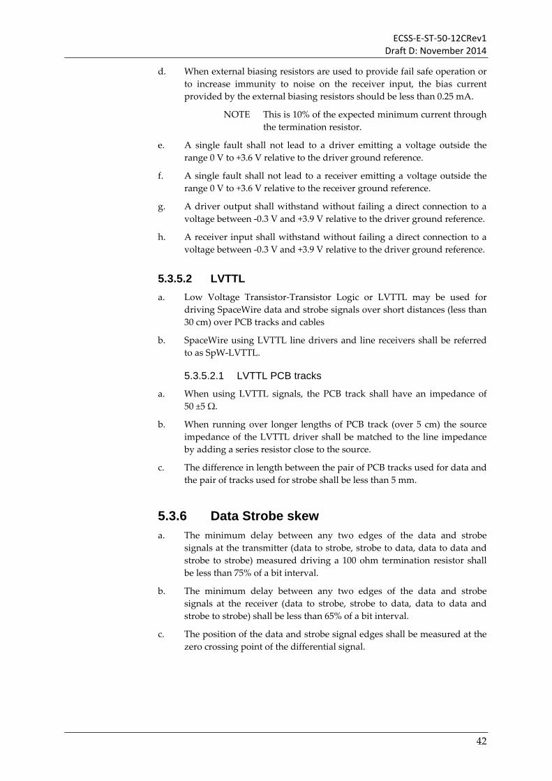
5.4 Encoding layer The encoding layer specifies the encoding/decoding of characters into symbols, the serialisation/de-serialisation of the encoded symbols into a bit stream, and the data-strobe encoding/decoding of the serial bit stream.
5.4.1 Serialisation and de-serialisation a. Characters and control codes shall be encoded, serialised, data-strobe
encoded and transmitted in the order in which they are received from the data link layer.
b. Received characters and control codes shall be passed to the data link layer in the order in which they are received.
c. Only received characters and control codes that do not contain a parity error shall be passed to the data link layer.
d. Received characters and control codes shall be passed to the data link layer only after a Null has been received without error, i.e. gotNull is asserted (see section 5.4.4).
e. The operation of the encoding layer shall be controlled by the data link layer using the following control flags:
1. Transmit enable, which shall enable the transmitter (character encoder, serialiser, data-strobe encoder and line driver) when asserted and reset it when de-asserted.
2. Receive enable, which shall enable the receiver (line receiver, data-strobe decoder, de-serialiser and character decoder) when asserted and reset it when de-asserted.
f. The encoding layer shall inform the data link layer of changes in the encoding layer indicated by the following status flags:
1. Disconnect, which shall indicate that the link has been disconnected.
2. Receive error, which shall indicate that an error has been detected in a received symbol, e.g. a parity error.
3. gotNull, which indicates that a Null character has been received without any parity errors.
5.4.2 Character and control code encoding In this section the encoding of SpaceWire characters and control codes is specified.
5.4.2.1 Data characters a. A data character shall be encoded in 10-bits with the resulting data
symbol containing a parity bit, a data-control flag and eight bits of data as illustrated in Figure 5-10.
43

ECSS-E-ST-50-12CRev1 Draft D: November 2014
b. The data-control flag shall be set to zero to indicate that the current symbol holds a data character.
c. The eight-bit data value shall be transmitted least significant bit first.
P 0 D0 D1 D2 D3 D4 D5 D6 D7
LSB MSB
Data-control flag
Parity bit
Data
Figure 5-10: Data character encoding
5.4.2.2 Control characters a. A control character shall be encoded in four bits with the resulting
control symbol containing a parity bit, a data-control flag and a two-bit control type as illustrated in Figure 5-11.
b. The data-control flag shall be set to one to indicate that the current symbol holds a control character.
c. A flow control token (FCT) shall be encoded as a control symbol with the two-bit control type set to 0b00.
NOTE The FCT is used in the data link layer to manage the flow of N-Chars over a SpaceWire link.
d. An end of packer marker (EOP) shall be encoded as a control symbol with the two-bit control type set to 0b01.
NOTE The EOP is used in the data link layer to mark the end of a packet indicating that the packet was transferred with no parity error being detected.
e. An error end of packet marker (EEP) shall be encoded as a control symbol with the two-bit control type set to 0b10.
NOTE The EEP is used in the data link layer to terminate a packet prematurely at the point where the error occurred; indicating that an error occurred while the packet was being transferred.
f. An escape character (ESC) shall be encoded as a control symbol with the two-bit control type set to 0b11.
44

ECSS-E-ST-50-12CRev1 Draft D: November 2014
P 1 0 0 FCT Flow Control Token
P 1 0 1 EOP Normal End of Packet
P 1 1 0 EEP Error End of Packet
P 1 1 1 ESC Escape
LSB MSB
Data-control flag
Parity bit
Type
Figure 5-11: Control character encoding
5.4.2.3 Control codes a. The ESC shall be used as the first character in a control code.
b. The Null control code shall be encoded as an ESC followed by a flow control token (FCT) as illustrated in Figure 5-12.
NOTE The parity bit (P) in the middle of the control code is zero, in accordance with clause 5.4.2.4).
NOTE Null is passed to the encoding layer by the data link layer whenever a link is not sending data or control symbols, to keep the link active and to support link disconnect detection (see clause 5.4.8).
P 1 1 1
Null
0 1 0 0
ESC FCT
Figure 5-12: Null control code encoding
c. The broadcast code (BC) shall be encoded as an ESC followed by a single data character as illustrated in Figure 5-13.
NOTE The parity bit (P) in the middle of the broadcast code is one, in accordance with clause 5.4.2.4).
NOTE The broadcast code is used for time-codes and distributed interrupt codes.
d. The eight bits of data in the data character of a broadcast code shall be separated into two fields:
1. The most significant two bits (B7:6) form the type field.
2. The least significant six bits (B5:0) form the value field.
45

ECSS-E-ST-50-12CRev1 Draft D: November 2014
e. The type field shall be set to 0b00 for a time-code.
f. The type field shall be set to 0b10 for a distributed interrupt code.
LSB MSB0 B0 B1 B2 B3 B4 B5 B6 B71
Broadcast code
ESC Data Character
1 1 1P
Value Type
Figure 5-13: Broadcast code encoding
5.4.2.4 Parity a. A parity bit shall be assigned to each encoded data or control character to
support the detection of transmission errors.
b. The parity bit shall cover the previous eight bits of an encoded data character or two bits of an encoded control character, the current parity bit, and the current data-control flag, as illustrated in Figure 5-14.
c. The parity bit shall be set to produce odd parity so that the total number of 1’s in the field covered is an odd number.
P 0 X X XXXX XX P 01 1 P 01 0
Data Character EOP FCT
ParityCoverage
ParityCoverage
Figure 5-14: Parity coverage
5.4.3 Data signalling rate
5.4.3.1 Initial operating data signalling rate a. After a reset or disconnect (see clause 5.4.8) an output port shall start
operating at a data signalling rate of 10 ±1 Mb/s.
b. The SpaceWire output port shall operate at 10 ±1 Mb/s until set to operate at a different data signalling rate.
NOTE The aim is to provide all systems with a common, slow, initial data signalling rate so that system operation can be validated before switching to higher and possibly widely different data signalling rates.
46

ECSS-E-ST-50-12CRev1 Draft D: November 2014
NOTE This initial slow data signalling rate is applicable to all SpaceWire output ports, but they need not be capable of higher data signalling rates.
c. The SpaceWire output port operating rate shall only be changed when the link connection has been made and the link state machine has entered the Run state (see clause 5.5.7.6).
5.4.3.2 Minimum data signalling rate a. The minimum data signalling rate at which an output port shall operate
is 2 Mbps.
NOTE The minimum data signalling rate is the lowest data signalling rate at which a SpaceWire link can operate which is determined by the disconnect timeout (clause 5.4.7) to be greater than 1.18 Mbps, i.e. 1/850 ns.
b. An output port may have a minimum data signalling rate of more than 2 Mbps but at most 10 Mbps + 10%.
5.4.3.3 Maximum data signalling rate a. The maximum data signal rate shall be the highest data signalling rate at
which a SpaceWire link can operate taking into account signal attenuation, skew and jitter.
b. The maximum data signalling rate shall be specified for each implementation.
c. The maximum signalling data rate shall be the fastest data signalling rate that a SpaceWire link can operate whilst maintaining an open eye pattern as detailed in clause 5.3.5.1.2.
5.4.3.4 Operational data signalling rates a. Once in the Run state (see clause 5.5.7.6) it shall be possible to change the
output port data signalling rate from the initial data signalling rate to the required operating data signalling rate.
b. The output port at one end of a link shall be able to operate at a different data signalling rate to the output port at the other end of the link.
NOTE The link is able to run at different speeds in each direction. Normally it is beneficial to have both directions of the link running at the same speed because a wide variation in speed would slow the FCTs being returned on the slower direction of the link and thus throttle the data rate in the faster direction.
c. Output ports within a network shall be able to operate at different data signalling rates.
NOTE Overall system performance is improved if all links in a network run at the same or similar speed, since a
47

ECSS-E-ST-50-12CRev1 Draft D: November 2014
packet will be held up on a fast link if it is elsewhere being routed over a slower link (see clause 5.6.4.7).
5.4.4 Null detection a. Null detection shall be enabled whenever the receiver is enabled.
b. The gotNull condition shall be asserted when a Null is received to indicate that a Null has been received.
c. The gotNull condition shall only be cleared when the link state machine enters the ErrorReset state (see clause 5.5.7.1).
d. Null detection shall include all three parity bits related to the Null, i.e. the parity bit that covers the data-control flag of the ESC character, the parity bit that covers the ESC character, and the parity bit that covers the FCT character, so gotNull is asserted when the 011101000 sequence of bits is received as illustrated in Figure 5-15.
NOTE During initialization the character following a Null is a control character (either another Null or an FCT) so the last parity bit of the Null is zero. See clause 5.4.7 for the format of first Null transmitted by a SpaceWire interface.
0 1 1 1 0 1 0 0
ESC FCT
Null
P C 1 1 P C 0 0
1 0 1 1 0 1
Required Null Detection Sequence
Data bit stream
P C
Figure 5-15: Null detection sequence
e. If a parity error occurs within the Null detection sequence, the gotNull condition shall not be asserted.
5.4.5 Parity error a. Parity errors shall be detected by the input port.
b. Parity detection shall be enabled whenever the receiver is enabled and after the first Null has been received.
c. A parity error shall be detected when the parity of a received data character or control character is not odd, i.e. when there is an even number of bits set to one in the character including the parity bit.
5.4.6 Data strobe encoding and decoding a. The data bit stream resulting from the serialisation of the symbols to be
transmitted shall be encoded using two signals, Data and Strobe, as follows:
48

ECSS-E-ST-50-12CRev1 Draft D: November 2014
1. The Data signal shall follow the data bit stream, i.e. be high when the data bit is 1 and low when the data bit is 0.
2. The Strobe signal shall change state whenever the Data does not change from one bit to the next.
NOTE The Data-Strobe encoding is illustrated in Figure 5-16.
0 0 1 1 0 1 1 00 1DataDS
CLK
Figure 5-16: Data-Strobe (DS) encoding
b. The Data and Strobe signals shall be set to zero on power up reset.
c. When the SpaceWire output port is reset it shall be a controlled reset avoiding simultaneous transitions of Data and Strobe signals.
NOTE For example, after stopping transmission the Strobe signal can be reset first, followed by the Data signal. This prevents a simultaneous transition on the data and strobe signals which can cause some IEEE 1355-1995 devices to enter an unrecoverable fault state.
d. When a SpaceWire output port has been transmitting characters and the link state machine enters the ErrorReset state (see clause 5.5.7.1) the data and strobe signals shall be reset with a delay between the reset of the strobe followed by data signal or reset of the data followed by strobe signal.
e. The delay between the reset of the Strobe signal and the Data signal shall be between 500 ns (the period of slowest permitted transmit bit rate, 2 Mbps) and the period of the fastest transmit time for the particular transmitter which is dependent upon implementation.
f. The SpaceWire receiver shall be tolerant of simultaneous transitions on the Data and Strobe lines, i.e. the receiver shall not lock up when a simultaneous transition occurs.
NOTE Simultaneous transitions on the Data and Strobe lines are not part of the normal operation of SpaceWire. They can occur, however, either when a SpaceWire cable is plugged in while the transmitter is trying to make a connection, or when the LVDS driver or receiver circuits are enabled while the transmitter is trying to make a connection.
49
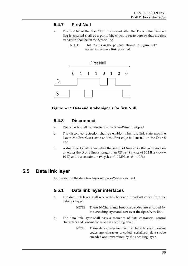
ECSS-E-ST-50-12CRev1 Draft D: November 2014
5.4.7 First Null a. The first bit of the first NULL to be sent after the Transmitter Enabled
flag is asserted shall be a parity bit, which is set to zero so that the first transition shall be on the Strobe line.
NOTE This results in the patterns shown in Figure 5-17 appearing when a link is started.
0 1 1 1 0 1 0 0
First Null
D
S
Figure 5-17: Data and strobe signals for first Null
5.4.8 Disconnect a. Disconnects shall be detected by the SpaceWire input port.
b. The disconnect detection shall be enabled when the link state machine leaves the ErrorReset state and the first edge is detected on the D or S line.
c. A disconnect shall occur when the length of time since the last transition on either the D or S line is longer than 727 ns (8 cycles of 10 MHz clock + 10 %) and 1 μs maximum (9 cycles of 10 MHz clock - 10 %).
5.5 Data link layer In this section the data link layer of SpaceWire is specified.
5.5.1 Data link layer interfaces a. The data link layer shall receive N-Chars and broadcast codes from the
network layer.
NOTE These N-Chars and broadcast codes are encoded by the encoding layer and sent over the SpaceWire link.
b. The data link layer shall pass a sequence of data characters, control characters and control codes to the encoding layer.
NOTE These data characters, control characters and control codes are character encoded, serialised, data-strobe encoded and transmitted by the encoding layer.
50

ECSS-E-ST-50-12CRev1 Draft D: November 2014
c. The data link layer shall receive data characters, control characters and control codes from the encoding layer in the order they are received.
d. The data link layer shall pass N-Chars and broadcast codes that are received without parity error to the network layer.
e. The data link layer shall indicate to the Network layer when it is able to accept another N-Char for sending.
f. The data link layer shall indicate to the Network layer when it has an N-Char ready for passing to the Network layer.
g. The data link layer shall indicate to the Network layer when it has a broadcast code ready for passing to the Network layer.
h. The data link layer shall control the operation of the encoding layer using the following control flags:
1. Transmit enable, which shall enable the transmitter (character encoder, serialiser, data-strobe encoder and line driver) when asserted and reset it when de-asserted.
2. Receive enable, which shall enable the receiver (line receiver, data-strobe decoder, de-serialiser and character decoder) when asserted and reset it when de-asserted.
i. The data link layer shall respond to changes in the encoding layer indicated by the following status flags:
1. Disconnect, which shall indicate that the link has been disconnected.
2. Receive error, which shall indicate that an error has been detected in a received symbol, e.g. a parity error.
3. gotNull, which indicates that a Null character has been received without any parity errors.
5.5.2 Data link layer management parameters a. The data link layer shall be controlled using the following management
parameters:
1. Enable, which when asserted allows a SpaceWire port to operate.
NOTE Disable is the inverse of Enable.
2. LinkStart, which when asserted causes an enabled SpaceWire port to attempt to start the SpaceWire link by sending Nulls.
3. AutoStart, which when asserted causes an enabled SpaceWire port to start the SpaceWire link as soon as a Null is received.
NOTE This is the minimum set of management parameters to allow operation of the SpaceWire link.
b. The data link layer should provide the following status information:
1. Current state of data link layer state machine;
2. Error flags:
51

ECSS-E-ST-50-12CRev1 Draft D: November 2014
(a) Disconnect;
(b) Parity Error;
(c) ESC Error;
(d) Credit Error;
3. Values of the transmit and receive credit counters.
5.5.3 Sending priority a. The order of priority for sending of characters and control codes shall be
as follows:
1. Broadcast codes, highest priority;
2. FCTs;
3. N-Chars;
4. Nulls, lowest priority.
b. When the link state machine is in the Run state and sending of a broadcast code is requested, it shall be sent as soon as the SpaceWire output port has finished sending the current character or control code.
c. When sending of an FCT is requested, it shall be sent as soon the current character or control code has been sent provided that:
1. No broadcast code is waiting to be sent.
d. When the link state machine is in the Run state and an N-Char is available in the transmit buffer, it shall be sent as soon the current character or control code has been sent provided that:
1. No broadcast code is waiting to be sent.
2. No FCT is waiting to be sent.
3. The transmit control credit count is above zero.
e. When no broadcast code, FCT or N-Char is ready to be sent, a Null shall be sent to indicate that the link is still active.
NOTE This prevents the disconnect detection mechanism from being triggered at the far end of the link.
5.5.4 Link errors
5.5.4.1 ESC error a. An escape character (ESC) followed by ESC, EOP or EEP is an invalid
sequence and when received shall produce an ESC error.
NOTE ESC followed by FCT is a Null and ESC followed by a data character is a broadcast code.
b. ESC errors shall be detected by the input port.
52

ECSS-E-ST-50-12CRev1 Draft D: November 2014
c. ESC error detection shall be enabled after the first Null has been received (gotNull asserted).
5.5.5 Flow control a. The flow of N-Chars across a link shall be controlled using flow control
tokens sent from one end of the link (end A) to the other end (end B) to signify that end A is ready to receive some more data.
b. Each flow control token shall be exchanged for eight N-Chars.
c. An FCT shall be sent out by a SpaceWire port when that port is ready to receive a further eight N-Chars.
d. A port shall not transmit any N-Chars until it has received one or more FCTs to indicate that the port at the other end of the link is ready to receive N-Chars.
e. The port shall keep a credit count of the number of N-Chars it has been authorized to send (transmit credit count), as follows:
1. Each time a port receives an FCT it shall increment its transmit credit count by eight.
2. Whenever a port sends an N-Char it shall decrement its transmit credit count by one.
NOTE EOP and EEP are N-Chars and thus must be credit counted even when empty packets are discarded.
f. If the transmit credit count reaches zero the port shall cease sending N-Chars until it receives another FCT which will increase the transmit credit count to eight.
g. When the transmit credit count is zero the port shall continue to send L-Chars.
h. The transmit credit count shall be set to zero whenever the link state machine enters the ErrorReset state.
i. The transmit credit count shall have a maximum value of 56 which corresponds to seven FCTs.
j. A maximum of seven FCTs shall be outstanding at any time.
k. If an FCT is received which would make the transmit credit counter exceed its maximum value:
1. The transmit counter shall not be incremented.
2. A credit error shall be raised (see clause 5.5.6).
l. When the link is initialised or re-initialised, one FCT shall be sent for every eight N-Chars that can be held in the receive FIFO up to the maximum of seven FCTs.
m. The port shall keep a credit count of the number of N-Chars it has asked for by sending FCTs and has yet to receive (receive credit count) as follows:
53

ECSS-E-ST-50-12CRev1 Draft D: November 2014
1. Increment the receive credit count by eight each time an FCT is transmitted
2. Decrement the receive credit count by one each time an N-Char is received.
n. The receive credit count shall be set to zero whenever the link state machine enters the ErrorReset state.
o. The receive credit count shall have a maximum value of 56, corresponding to seven FCTs.
p. A receive credit count may have a maximum value of less than 56 if the port can hold fewer than 56 received N-Chars.
q. A port may hold more received N-Chars than the maximum receive credit count value.
r. An FCT shall only be sent when there is room in the port to receive another eight more N-Chars and when the receive credit count has a value of eight or more less than its maximum value.
5.5.6 Flow control errors a. A credit error shall be detected when either of the following conditions
occur:
1. An N-Char is received when the receive credit counter is zero.
2. An FCT is received which would cause the transmit counter to exceed its maximum permitted value.
NOTE A credit error indicates that some otherwise undetected error has occurred on the link, which has caused the corruption of the credit count.
5.5.7 Link state machine a. The link state machine shall control the initialisation of the SpaceWire
link, establishing the connection and responding to control requests.
b. When an error occurs on the link, the link state machine shall recover from those errors allowing normal link operation to resume when possible.
NOTE The state diagram for the link initialisation state machine is illustrated in Figure 5-18.
54

ECSS-E-ST-50-12CRev1 Draft D: November 2014
Error events and resulting transitions shown in red.Necessary conditions not specified in the original standard are shown in blue.
PortReset
ReadyReset Tx
Enable Rx
StartedSend NullsEnable Rx
ErrorResetReset TxReset Rx
ErrorWaitReset Tx
Enable Rx
Enabled AND LinkStart OREnabled AND AutoStart AND gotNull
Enabled AND After 6.4 µs
Enabled ANDAfter 12.8 µs
Enabled ANDgotNull AND
Sent Null
Disconnect ORParity Error ORESC Error ORCredit Error ORDisabled Run
Enable sending Time-Codes/
FCTs/N-Chars/NullsEnable Rx
Disconnect ORParity Error ORESC Error ORgotFCT ORgotN-Char OR
gotBC ORDisabled
Enabled ANDgotFCT AND
Sent FCT
ConnectingEnable sending
FCTs/NullsEnable Rx
Disconnect OR Parity Error OR
ESC Error OR gotFCT OR
gotN-Char ORgotBC OR
Disabled
Disconnect ORParity Error ORESC Error ORgotFCT ORgotN-Char ORgotBC ORafter 12.8 µs ORDisabled
Disconnect ORParity Error OR
ESC Error ORgotN-Char OR
gotBC OR after 12.8 µs OR
Disabled
Figure 5-18: Link state machine
NOTE Disconnect Error is only enabled after the first transition on the data or strobe line.
NOTE Parity Error, ESC Error, gotFCT, gotN-Char and got-BC are only enabled after the first Null has been received (i.e. gotNull asserted).
NOTE The transition from the Started to ErrorReset has “after 12.8 μs” in black (dark text) which is intentional as this transition is normal operation and not an error condition. It occurs when this end of the line is trying to start and the other end is disabled. The transition from Connecting to ErrorReset has “after 12.8 μs” in red (lighter text) because it is an error: although a Null has been received indicating that the other end of the link is active, no FCT is received within 12.8 μs so it is a fault.
c. The after 6.4 µs condition represents a 6.4 µs (nominal) timing delay which shall have a duration of between 5.82 µs (i.e. 64 cycles of 10 MHz + 10% clock) to 7.22 µs (i.e. 65 cycles of 10 MHz - 10% clock).
d. The after 12.8 µs condition represents a 12.8 µs (nominal) timing delay which shall have a duration of between 11.64 µs (i.e. 128 cycles of 10 MHz + 10% clock) to 14.33 µs (i.e. 129 cycles of 10 MHz - 10% clock).
e. When Port Reset is asserted the TX FIFO and RX FIFO shall be cleared.
55

ECSS-E-ST-50-12CRev1 Draft D: November 2014
5.5.7.1 ErrorReset state a. The link state machine shall enter the ErrorReset state on one of the
following conditions:
1. Port Reset is asserted.
2. The port is disabled or a disconnect, parity error, ESC error, gotFCT, gotN-Char or gotBC event occurs while in the ErrorWait state.
3. The port is disabled or a disconnect, parity error, ESC error, gotFCT, gotN-Char or gotBC event occurs while in the Ready state.
4. The port is disabled or a disconnect, parity error, ESC error, gotFCT, gotN-Char or gotBC event occurs while in the Started state.
5. The link state machine has been in the Started state for more than 12.8 μs.
6. The port is disabled or a disconnect, parity error, ESC error, gotN-Char or gotBC event occurs while in the Connecting state.
7. The link state machine has been in the Connecting state for more than 12.8 μs.
8. The port is disabled (enable de-asserted) or a disconnect, parity error, ESC error or credit error occurs while in the Run state.
b. When in the ErrorReset state the link state machine shall initiate the following actions:
1. Start a 6.4 μs timer on entering the ErrorReset state after Port Reset is disabled.
2. De-assert the Transmit Enable control flag.
3. De-assert the Receive Enable control flag.
NOTE This will cause the Encoding layer to clear the gotNull condition.
4. Set the transmit credit counter to zero.
5. Set the receive credit counter to zero.
6. Clear the gotFCT condition.
c. When in the ErrorReset state the link state machine should initiate the following actions:
1. Discard any broadcast code pending to be sent.
d. The Link state machine shall leave the ErrorReset state on the following condition:
1. When Port Reset is de-asserted and enable is asserted and 6.4 μs (at least) has elapsed since entering the ErrorReset state, move to the ErrorWait state.
56

ECSS-E-ST-50-12CRev1 Draft D: November 2014
5.5.7.2 ErrorWait state a. The Link state machine shall enter the ErrorWait state on the following
condition:
1. From the ErrorReset state, when the Port Reset is de-asserted and enable is asserted and 6.4 μs (at least) has elapsed since entering the ErrorReset state.
b. When in the ErrorWait state the Link state machine shall initiate the following actions:
1. Start a 12.8 μs timer on entering the ErrorWait state.
2. De-assert the Transmit Enable control flag.
3. Assert the Receive Enable control flag, but do not pass any N-Chars to the Encoding Layer and do not register any received broadcast codes.
c. The Link state machine shall leave the ErrorWait state on one of the following conditions which are to be evaluated in the order given:
1. When Port Reset is asserted, move to the ErrorReset state.
2. When the port is disabled (enable de-asserted), move to the ErrorReset state.
3. When a disconnect occurs, move to the ErrorReset state.
4. When a parity error occurs move to the ErrorReset state.
5. When an ESC error occurs), move to the ErrorReset state.
6. When an FCT, N-Char or broadcast code is received move to the ErrorReset state.
7. If enabled, 12.8 μs after entering the ErrorWait state, move to the Ready state.
5.5.7.3 Ready state a. The Link state machine shall enter the Ready state on the following
condition:
1. From the ErrorWait state, when enable is asserted and 12.8 μs after entering the ErrorWait state.
b. When in the Ready state the Link state machine shall initiate the following actions:
1. De-assert the Transmit Enable control flag.
2. Assert the Receive Enable control flag, but do not pass any N-Chars to the Encoding Layer and do not register any received broadcast codes.
c. The Link state machine shall leave the Ready state on one of the following conditions:
1. When Port Reset is asserted, move to the ErrorReset state.
57

ECSS-E-ST-50-12CRev1 Draft D: November 2014
2. When the port is disabled (enable de-asserted), move to the ErrorReset state.
3. When a disconnect occurs, move to the ErrorReset state.
4. When a parity error occurs, move to the ErrorReset state.
5. When an ESC error occurs, move to the ErrorReset state.
6. When an FCT, N-Char or broadcast code is received, move to the ErrorReset state.
7. When enable is asserted and LinkStart is asserted, move to the Started state.
8. When enable is asserted and AutoStart is asserted and a Null has been received (gotNull asserted), move to the Started state.
5.5.7.4 Started state a. The Link state machine shall enter the Started state on one of the
following conditions:
1. From the Ready state, when enable is asserted and LinkStart is asserted.
2. From the Ready state, when enable is asserted and AutoStart is asserted and a Null has been received (gotNull asserted).
b. When in the Started state the Link state machine shall initiate the following actions:
1. Start a 12.8 μs timer on entering the Started state.
2. Send Nulls.
3. Assert the Receive Enable control flag, but do not pass any N-Chars to the Encoding Layer and do not register any received broadcast codes.
c. The Link state machine shall leave the Started state on one of the following conditions:
1. When Port Reset is asserted, move to the ErrorReset state.
2. When the port is disabled (enable de-asserted), move to the ErrorReset state.
3. When a disconnect occurs, move to the ErrorReset state.
4. When a parity error occurs, move to the ErrorReset state.
5. When an ESC error, move to the ErrorReset state.
6. When an FCT, N-Char or broadcast code is received, move to the ErrorReset state.
7. When enable is asserted, at least one Null has been sent and a Null has been received (gotNull asserted), move to the Connecting state.
58

ECSS-E-ST-50-12CRev1 Draft D: November 2014
NOTE The Null that is received causing the gotNull condition to be asserted could have occurred in the ErrorWait, Ready or Started state.
8. 12.8 μs after entering the Started state, move to the ErrorReset state.
5.5.7.5 Connecting state a. The Link state machine shall enter the Connecting state on the following
condition:
1. From the Started state, when enable is asserted and a Null has been received (gotNull asserted).
b. When in the Connecting state the Link state machine shall initiate the following actions:
1. Start a 12.8 μs timer on entering the Connecting state.
2. Enable sending of FCTs.
3. Send Nulls when there is nothing else to send.
4. Send FCTs and Nulls.
5. Assert the Receive Enable control flag.
6. When gotFCT has been asserted, pass any received N-Chars to the Encoding Layer and register any received broadcast codes.
NOTE It is necessary to write the N-Chars into the FIFO and register any broadcast codes in this state once gotFCT has been asserted because it is possible that the far end of the link has initialized and is running at 200 Mbits/s, for example, so that in the time the state machine is in the Connecting state one or more N-Chars or broadcast codes are received after the FCT.
c. The Link state machine shall leave the Connecting state on one of the following conditions:
1. When Port Reset is asserted, move to the ErrorReset state.
2. When the port is disabled (enable de-asserted), move to the ErrorReset state.
3. When a disconnect occurs, move to the ErrorReset state.
4. When a parity error occurs, move to the ErrorReset state.
5. When an ESC error occurs, move to the ErrorReset state.
6. When enable is asserted, at least one FCT has been sent and an FCT has been received (gotFCT asserted), move to the Run state.
7. When an N-Char or broadcast code is received and no FCT has been received, move to the ErrorReset state.
8. 12.8 μs after entering the Connecting state, move to the ErrorReset state.
59

ECSS-E-ST-50-12CRev1 Draft D: November 2014
5.5.7.6 Run state a. The Link state machine shall enter the Run state on the following
condition:
1. From the Connecting state, when enable is asserted, at least one FCT has been sent and an FCT is received.
b. When in the Run state the Link state machine shall initiate the following actions:
1. Enable sending of FCTs, N-Chars and broadcast codes.
2. Pass Nulls to the Encoding Layer when there is nothing to send.
3. Assert the Receive Enable control flag.
4. Pass received N-Chars and broadcast codes to the Encoding Layer.
5. Pass any received broadcast codes to the Network Layer.
c. The Link state machine shall leave the Run state on one of the following conditions:
1. When Port Reset is asserted, move to the ErrorReset state.
2. When the port is disabled (enable de-asserted), move to the ErrorReset state.
3. When a disconnect occurs, move to the ErrorReset state.
4. When a parity error occurs, move to the ErrorReset state.
5. When an ESC error occurs, move to the ErrorReset state.
6. When a credit error occurs, move to the ErrorReset state.
5.5.8 Link error recovery a. A link error recovery state machine shall control the recovery of the link
from errors.
NOTE The link error recovery state machine is illustrated in Figure 5-19.
60

ECSS-E-ST-50-12CRev1 Draft D: November 2014
PortReset
Recovery
Normal
Disconnect ORParity Error ORESC Error ORCredit Error ORDisabled while in Run state
Error recovery complete
Figure 5-19: Link error recovery state machine
5.5.8.1 Normal state a. The Link Error Recovery state machine shall enter the Normal state on
one of the following conditions:
1. Port Reset is asserted.
2. Error recovery is completed in the Recovery state.
b. When in the Normal state the Link Error Recovery state machine shall do nothing.
c. The Link Error Recovery state machine shall leave the Normal state on the following conditions:
1. When the Link state machine is in the Run state and the port is disabled (enable de-asserted), the Link Error Recovery state machine shall move to the Recovery state.
2. When the Link state machine is in the Run state and a Disconnect, Parity Error, ESC Error, or Credit Error occurs, the Link Error Recovery state machine shall move to the Recovery state.
5.5.8.2 Recovery state a. The Link state machine shall enter the Recovery state on one of the
following conditions:
1. Port is disabled (enable de-asserted) in the Normal state.
2. A disconnect occurs in the Normal state.
3. A parity error occurs in the Normal state.
4. An ESC error occurs in the Normal state.
5. A credit error occurs in the Normal state.
b. When in the Recovery state the Link state machine shall initiate the following actions:
61

ECSS-E-ST-50-12CRev1 Draft D: November 2014
1. If currently sending a packet, discard the remainder of the packet that has not yet been sent, i.e. if one or more N-Chars have been sent since the link reached the Run state AND the last character sent was not an EOP or EEP, read the transmit FIFO and discard the characters read until an EOP or EEP has been read and discarded.
NOTE Because the remainder of a packet is discarded after an error, very large packets can cause the link to halt for a long period of time while the packet is spilt. It is important to bear this in mind when determining the size of packets to use in a particular application.
2. If the last character written to the receive FIFO was a data character, write an EEP to the receive FIFO.
3. An EEP may be added to the receive FIFO when the last character written was an EOP or EEP.
4. If an EEP is to be written to the receive FIFO and that FIFO is full preventing an EEP being written, wait until there is space in the receive FIFO and then write the EEP.
5. Record the cause of the error in a status register.
NOTE The error recovery process is illustrated in Figure 5-20
NOTE If the receive FIFO is full, it will not be possible for the transmitter to send an FCT, which means link initialisation cannot take place successfully. The Link state machine cycles through ErrorReset, ErrorWait, Ready and Connected states until space is made in the receive FIFO. When there is room for at least eight N-Chars, at least one FCT can be sent so the link initialisation process is then able to complete successfully.
NOTE If the remainder of a large packet has to be spilt it can take significant time, the link will initialize but not be able to send a packet until the remainder of the packet being spilt has been discarded.
c. The Link state machine shall leave the Recovery state on the following conditions:
1. When Port Reset is asserted, move to the Normal state.
2. When error recovery is complete, move to the Normal state.
62

ECSS-E-ST-50-12CRev1 Draft D: November 2014
FIFOsBUFFERS FIFOs BUFFERSLINK
EOP
EOPTX
RX TX
RX
1. Detect Error
EOP
EOPTX
RX TX
RX
2. Disconnect
EOPTX
RX TX
RX
3. Add EEP to RX FIFO
EOP
EOPTX
RX TX
RX
4. Delete Data in TX until next EOP
EOPTX
RX TX
RX
5. Reconnect
EOP
EOPTX
RX TX
RX
6. Continue Operation
ERROR
EEP
EEP
EOP EEP
EEP
EOP
EOP
EOP
EOP
EOP EOP
EOP
EEP
EEP
EEP
EEP
Figure 5-20: Link error recovery process
5.5.9 Accepting broadcast codes for sending a. Broadcast codes should only be accepted for sending when the link state
machine is in the Run state.
b. Broadcast codes passed to the data link layer by the network layer should be discarded unless the link state machine is in the Run state.
NOTE This prevents a broadcast code from being passed to the data link layer and sent some significant time later when the link is started.
5.6 SpaceWire Network
5.6.1 SpaceWire packets
5.6.1.1 SpaceWire packet a. A SpaceWire packet shall comprise one or more data characters followed
by an end of packet marker (EOP) or error end of packet marker (EEP).
b. The start of a packet shall be either:
63

ECSS-E-ST-50-12CRev1 Draft D: November 2014
1. The first data character sent after a link is initialised or re-initialised following a disconnect.
2. The data character that immediately follows an EOP or EEP i.e. the first data character after the end of the previous packet.
c. The end of a packet shall be indicated by an EOP or EEP.
d. The packet shall contain one or more data characters.
e. A packet may contain zero data characters.
NOTE In this case the packet will be discarded by the first router that it encounters.
f. Zero or more data characters at the front of a packet shall form a destination address.
g. The remaining data characters, following the destination address and up to the EOP or EEP, shall form the cargo.
NOTE The format of a SpaceWire packet is illustrated in Figure 5-21.
Destination Address Cargo EOP/EEP
Figure 5-21: SpaceWire packet format
5.6.1.2 N-Char interleaving a. N-Chars from one packet shall not be interleaved with N-Chars from
another packet. NOTE N-Chars can be interleaved with FCTs, Nulls and
broadcast codes as explained in clause 5.5.3.
5.6.2 Broadcast codes a. A time-code shall be a broadcast code with the broadcast code type set to
0b00.
b. A distributed interrupt code shall be a broadcast code with the broadcast code type set to 0b10.
c. A broadcast code that has a broadcast code type set to 0b01 or 0b11 shall be reserved and not used.
NOTE The specialisations of broadcast codes are illustrated in the UML diagram of Figure 5-22.
64

ECSS-E-ST-50-12CRev1 Draft D: November 2014
Broadcast Code
Interrupt Code
Broadcast Code Type = 0b10Interrupt Identifier
Holds last received
Interrupt Register
Active Interrupts
0..1
Time-Code
Broadcast Code Type = 0b00Time-Code Value
Holds last received
Time-Code Register
Last Time-Code
0..1
1..M
KEY
Association
1 or more
Made up of (aggregation)
Type of (specialisation)
EntityAttributes
Entity Name
Figure 5-22: Specialisations and relationships of a SpaceWire broadcast code
d. There shall be three types of distributed interrupt codes: interrupt code, interrupt acknowledgment code and extended interrupt code.
e. The order of priority with which the network layer shall pass different types of broadcast codes to the data link layer shall be as follows:
1. Time-code, highest priority;
2. Interrupt acknowledge code;
3. Interrupt code and extended interrupt code, lowest priority.
5.6.2.1 SpaceWire time-codes
5.6.2.1.1 Time-code master
a. At any time a network supporting time-code broadcasting shall have a single end point which is the time-code master and responsible for sending time-codes over the network.
b. The host system attached to the current time-code master end point shall pass time-codes to the end point for sending across the network.
c. When an end point receives a time-code from its host system it shall load the value of the time-code into its time-code register and request the output port to send the time-code.
NOTE The host system does not have to send time-codes with sequential values, but only those with sequential values will propagate across the network.
65

ECSS-E-ST-50-12CRev1 Draft D: November 2014
5.6.2.1.2 Valid time-code
a. The value field of a time-code shall contain a 6-bit time-code value, which is an unsigned binary integer.
NOTE The network layer time-code is illustrated in Figure 5-23.
LSB MSBID0 ID1 ID2 ID3 ID4 ID5 0 0
Time-Code
TypeValue
Figure 5-23 Network layer time-code
b. Each end point or router that has a time-code register shall use it to hold the value of the last received time-code.
c. After reset the time-code register shall be set to have a time-code value of zero.
d. When a time-code is received by an end point or router that has a time-code register its value shall be compared to the value contained in the time-code register.
e. If the received time-code has a value which is one more, modulo 64, than the value in the time-code register the received time-code shall be valid.
f. When a time-code is received by an end point or router that does not have a time-code register, the time-code shall be discarded.
5.6.2.1.3 Valid time-code in router
a. When a valid time-code is received by a router with a time-code register, it shall:
1. Request to send time-codes with the same value as the received valid time-code out through each of its output ports, except for the output port on which the valid time-code arrived.
2. Update the time-code register in the router to the value of the valid time-code.
5.6.2.1.4 Valid time-code in an end point
a. When a valid time-code is received by an end point with a time-code register it shall:
1. Indicate to the host system that a valid time-code has arrived and make the value of the time-code available to the host system.
2. Update the time-code register in the end point to the value of the valid time-code.
66

ECSS-E-ST-50-12CRev1 Draft D: November 2014
5.6.2.1.5 Invalid time-code in router
a. When an invalid time-code is received by a router with a time-code register, it shall update the time-code register in the router to the value of the received time-code.
5.6.2.1.6 Invalid time-code in an end point
a. When an invalid time-code is received by an end point with a time-code register, it shall update the time-code register in the end point to the value of the received time-code.
5.6.2.2 SpaceWire distributed interrupts
5.6.2.2.1 Interrupt codes
a. An interrupt code shall be used to broadcast an interrupt across the network.
NOTE The network layer interrupt code is illustrated in Figure 5-24.
LSB MSBIID0 IID1 IID2 IID3 IID4 0 0 1
Interrupt Code
Interrupt Identifier
TypeValue
Figure 5-24: Network layer interrupt code
b. Bits 0 to 4 of the value field of an interrupt code shall contain an interrupt identifier, which has a value between 0 and 31.
c. Bit 5 of the value field of an interrupt code shall be 0.
d. An interrupt code shall be associated with one of 32 possible interrupts as determined by the value of the interrupt identifier in the interrupt code.
NOTE If more interrupts are required it is possible to use the extended distributed interrupts, see clause 5.6.2.4.
5.6.2.2.2 Distributed interrupts in an end point
a. It shall be optional whether an end point supports distributed interrupts.
b. If an end point does not support distributed interrupts it shall discard any interrupt codes that it receives.
c. An end point supporting distributed interrupts shall:
1. Support between 1 and 32 separate interrupts;
2. Assign interrupt numbers to each of its interrupts.
5.6.2.2.3 End point sending interrupts
a. An end point shall indicate to the host system when it is ready to accept an interrupt code from the host for sending.
67

ECSS-E-ST-50-12CRev1 Draft D: November 2014
b. When an end point is ready to accept an interrupt code and receives a request from the host system to send an interrupt code, the interrupt code shall be passed to the output port of the end point for transmission over the SpaceWire network.
NOTE If several interrupt codes are rapidly produced with the same value, a router discards all but the first one, depending on the timing, see clause 5.6.2.2.5.
c. Once an interrupt code has been sent an end point shall only accept another interrupt code with the same interrupt identifier (IID) after a period of time longer than a configurable time-out period.
NOTE The configurable time-out period is set to be greater than the maximum interrupt time-out (TR) in the routers in the network for the distributed interrupt mechanism to function correctly, see clause 5.6.2.2.5.
5.6.2.2.4 End point receiving interrupts
a. An end point that is to receive distributed interrupts shall have an interrupt flag associated with each interrupt it is allowed to receive.
b. The interrupt flag associated with an interrupt number N shall be referred to as interrupt flag N.
c. The interrupt flag shall have two possible values:
1. Ready which means that the end point is ready to accept an interrupt code with an interrupt identifier corresponding to the number of the flag (N).
2. Active which means that the end point has received and is servicing an interrupt code with an interrupt identifier corresponding to the number of the flag (N).
d. When an end point receives an interrupt code from its port, the following actions shall be performed:
1. If the corresponding interrupt flag is set to Ready:
(a) The interrupt flag is set to active;
(b) The host system is informed that an interrupt has occurred with a specific interrupt identifier value.
2. If the corresponding interrupt flag is set to Active:
(a) The interrupt code is discarded and the interrupt flag remains unchanged.
e. The interrupt flags shall be readable by the host system so that it can determine which interrupt codes have arrived.
f. The Network Layer shall allow the host to set one or more specified Active interrupt flags back to the Ready state, to clear the interrupts that it has just serviced.
NOTE There is no time-out timer for the interrupt flags as this could result in received interrupts being cleared before they are read by the host system.
68

ECSS-E-ST-50-12CRev1 Draft D: November 2014
NOTE Routers in the network will prevent several interrupt codes with the same value arriving at a node, see clause 5.6.2.2.5.
5.6.2.2.5 Relaying interrupts in a router
a. It shall be optional whether a router supports distributed interrupts.
NOTE SpaceWire routers are detailed in clause 5.6.4.
b. If a router does not support distributed interrupts it shall discard any interrupt codes that it receives.
c. Each port of the router that support distributed interrupts shall be configurable to enable or disable the relaying of interrupt codes, i.e. the sending of a received interrupt code out of a port.
d. When a port of a router is disabled from sending and receiving interrupt codes it shall discard any received interrupt codes.
e. A router that supports distributed interrupts shall contain one 32-bit interrupt relay register that has one bit for each possible interrupt identifier with bit 0 of the register relating to interrupt identifier 0, bit 1 to interrupt identifier 1, and so on, to bit 31 relating to interrupt identifier 31.
f. The interrupt relay register may be less than 32-bits, in which case the interrupt identifiers supported will be interrupt identifier 0 (bit 0) to interrupt identifier N-1 (bit N-1) where N is the number of bits in the interrupt relay register.
g. On reset the interrupt relay register shall be cleared to zero.
h. Each bit of the interrupt relay register shall have its own interrupt time-out timer.
i. The interrupt time-out timers shall have a configurable time-out value, TR.
NOTE TR is configured to be more than the worst case propagation time of the interrupt code in the network, plus the maximum delay in an interrupt handler. If it is set to a lower value the distributed interrupts will not work properly.
j. When a port of a router is configured to accept interrupt codes and an interrupt code is received by a port of a router, the following actions shall be performed:
1. The bit in the interrupt relay register specified by the interrupt identifier value of the received interrupt code is checked.
2. If the specified bit is 0,
(a) That bit is set to 1.
(b) The received interrupt code is passed to all ports of the router for onward transmission except for the port on which the received interrupt code arrived and those that are disabled from forwarding interrupt codes.
69

ECSS-E-ST-50-12CRev1 Draft D: November 2014
(c) The interrupt time-out timer associated with the specified bit in the interrupt relay register is started.
3. If the specified bit is 1, the received interrupt code is discarded.
NOTE This prevents repeated propagation of interrupt codes in networks with circular connections.
k. When an interrupt time-out timer expires, the corresponding bit in the interrupt relay register shall be reset to 0.
5.6.2.3 Interrupts acknowledgement code a. Distributed interrupts may be acknowledged as detailed in the following
sub-clauses.
NOTE The use of interrupt acknowledgement codes are compatible with the use of interrupt codes as specified in clause 5.6.2.2 but not with the extended interrupt codes described in section 5.6.2.4.
5.6.2.3.1 Acknowledged interrupts
a. When it is required to send an acknowledgement to an interrupt back to the source of the interrupt two distributed interrupt codes shall be used: one interrupt code for the interrupt and one interrupt acknowledgement code for the interrupt acknowledgement.
b. The interrupt code for the interrupt that is to be acknowledged shall have an interrupt identifier in the range 0 to 31, with bit-5 of the value set to 0.
c. An interrupt acknowledgement code corresponding to an interrupt code with an interrupt identifier of value N (0 ≤ N ≤ 31) shall have an interrupt identifier of value N and have bit 5 of the value set to 1.
NOTE The interrupt code and interrupt acknowledgement code are illustrated in Figure 5-25.
70

ECSS-E-ST-50-12CRev1 Draft D: November 2014
LSB MSBIID0 IID1 IID2 IID3 IID4 0 0 1
Interrupt code
TypeValue
0 for interrupt
LSB MSBIID0 IID1 IID2 IID3 IID4 1 0 1
Interrupt acknowledgement code
TypeValue
1 for acknowledgement
Interrupt Identifier
Interrupt Identifier
Figure 5-25: Network layer interrupt code and interrupt acknowledge code
5.6.2.3.2 End point sending interrupt acknowledgements
a. When an interrupt flag is changed from Active to Ready by the host system, the Network Layer shall send an Interrupt Acknowledge code with same interrupt identifier value as the corresponding interrupt flag, i.e. with bit 5 set to one indicating that it is an interrupt acknowledgement code.
b. The interrupt flag for each interrupt supported by an end point shall be set to Active to indicate to the host system when an interrupt has arrived and that end point is consequently ready to accept an interrupt acknowledgement from the host for sending across the SpaceWire network.
c. When the interrupt flag is Active and the end point receives a request from the host system to acknowledge that interrupt, the end point shall:
1. After a time of at least TR since the interrupt being acknowledged was received, set the interrupt flag to Ready;
NOTE This period of time is necessary to prevent a copy of the interrupt that has taken a different, longer path through the network from triggering a second inadvertent interrupt when the first interrupt is acknowledged quickly by the host system.
2. Pass an interrupt acknowledgement to the output port of the end point for transmission over the SpaceWire network.
71

ECSS-E-ST-50-12CRev1 Draft D: November 2014
d. When the interrupt flag is Ready and the end point receives a request from the host system to acknowledge that interrupt, the end point shall:
1. Ignore the request to acknowledge that interrupt.
5.6.2.3.3 End point receiving interrupt acknowledgement
a. An end point that is to receive interrupt acknowledgements shall have an interrupt acknowledgement flag associated with each interrupt acknowledgement it is allowed to receive.
b. The interrupt acknowledgement flag associated with an interrupt acknowledgement number N shall be referred to as interrupt acknowledgement flag N.
c. The interrupt acknowledgement flag shall have two possible values:
1. Ready which means that the end point is ready to accept an interrupt acknowledgement code with an interrupt identifier corresponding to the number of the flag (N).
2. Active which means that the end point has received and is servicing an interrupt acknowledgement code with an interrupt identifier corresponding to the number of the flag (N).
d. When an end point receives an interrupt acknowledgment code from its port, the following actions shall be performed:
1. If the corresponding interrupt acknowledgement flag is set to Ready:
(a) The interrupt acknowledgement flag is set to Active;
(b) Start a timeout timer with an interval of at least TR.
NOTE This is used to prevent a copy of the interrupt that has taken a different, longer path through the network from triggering a second inadvertent interrupt when the first interrupt is acknowledged quickly by the host system.
(c) The host system is informed that an interrupt has occurred with a specific interrupt identifier value.
2. If the corresponding interrupt acknowledgement flag is set to Active:
(a) The interrupt acknowledgment code is discarded and the interrupt acknowledgement flag remains unchanged.
e. The interrupt acknowledgment flags shall be readable by the host system so that it can determine which interrupts have been acknowledged.
f. The Network Layer shall allow the host to change one or more specified Active interrupt acknowledgement flags back to the Ready state, to clear the interrupt acknowledgments that it has just serviced.
NOTE There is no time-out timer for the interrupt acknowledgment flags as this could result in received interrupt acknowledgments being cleared before they are read by the host system.
72

ECSS-E-ST-50-12CRev1 Draft D: November 2014
NOTE Routers in the network will prevent several interrupt acknowledgments with the same value arriving at a node, see clause 5.6.2.2.5.
NOTE Multiple sources and handlers of specific interrupts are permitted. One interrupt source in a network normally generates interrupts with a specific interrupt identifier value. It is, however, possible for more than one end point in a network to generate interrupts with the same interrupt identifier value, although this feature is to be used with care. It is possible for more than one end point in a network to handle interrupts with the same interrupt identifier value.
5.6.2.3.4 Acknowledged interrupts in a router
a. Routers supporting acknowledged interrupts shall use an interrupt acknowledgement to clear the corresponding interrupt in the interrupt relay register.
b. A router supporting acknowledged interrupts shall support a maximum of 32 interrupts.
c. Each port of a router that supports acknowledged interrupts shall be configurable to enable or disable the relaying of distributed interrupt codes, i.e. the sending of a received interrupt code out of a port.
d. The interrupt time-out timers shall have a configurable time-out value, TR.
NOTE TR is configured to be more than the worst case propagation time of the interrupt code in the network, plus the maximum delay in an interrupt handler, plus the worst case propagation time of the interrupt acknowledgement code in the network. If it is set to a lower value the distributed interrupts will not work properly.
e. A router supporting acknowledged interrupts shall respond to interrupt codes as detailed in clause 5.6.2.3.1.
f. When a router supporting acknowledged interrupts is configured to accept interrupt codes and an interrupt acknowledgement code is received, the following actions shall be performed:
1. The bit in the interrupt relay register specified by bits 0 to 4 of the interrupt identifier value of the received interrupt acknowledge code is checked.
2. If the specified bit is 1,
(a) That bit is reset to 0.
(b) The received interrupt acknowledgement code is passed to all ports of the router for onward transmission except for the port on which it arrived and those ports that are disabled from forwarding interrupt acknowledgement codes.
73

ECSS-E-ST-50-12CRev1 Draft D: November 2014
(c) The interrupt time-out timer associated with the specified bit in the interrupt relay register is stopped and set to its time-out value.
3. If the specified bit is 0, the received interrupt acknowledgement code is ignored.
NOTE This prevents repeated propagation of the interrupt acknowledgement codes in networks with circular connections.
g. When an interrupt time-out timer expires, the corresponding bit in the interrupt relay register shall be reset to 0.
NOTE This recovers from the situation when an interrupt acknowledgement is lost for some reason.
5.6.2.4 Extended interrupts a. The number of distributed interrupts may be increased to 64 as detailed
in the following sub-clauses.
NOTE Extended interrupts are compatible with distributed interrupts as specified in clause 5.6.2.2 but not with acknowledged interrupts as described in clause 5.6.2.3.
NOTE When it is required to indicate to an interrupt source that an interrupt has been received by the intended destination, that destination can emit a second interrupt to signal that the first interrupt was successfully received.
5.6.2.4.1 Extended interrupt codes
a. A distributed interrupt code shall be used to broadcast an extended interrupt across the network.
NOTE The network layer extended interrupt code is illustrated in Figure 5-26.
LSB MSBIID0 IID1 IID2 IID3 IID4 IID5 0 1
Extended Interrupt Code
Interrupt Identifier
TypeValue
Figure 5-26: Network layer extended interrupt code
b. Bits 0 to 5 of the value field of an interrupt code shall contain an interrupt identifier, which has a value between 0 and 63.
c. An extended interrupt code shall be associated with one of 64 possible interrupts as determined by the value of the interrupt identifier in the interrupt code.
74

ECSS-E-ST-50-12CRev1 Draft D: November 2014
5.6.2.4.2 Extended interrupts in an end point
a. It shall be optional whether an end point supports extended interrupts.
b. If an end point does not support distributed interrupts it shall discard any extended interrupt codes that it receives.
c. An end point supporting extended interrupts shall:
1. Support between 1 and 64 separate interrupts;
2. Assign interrupt numbers to each of its interrupts.
5.6.2.4.3 End point sending extended interrupts
a. An end point shall send extended interrupts in the same way as distributed interrupts, detailed in clause 5.6.2.2.3.
5.6.2.4.4 End point receiving interrupts
a. An end point that is to receive extended interrupts shall operate in the same way as an end point receiving distributed interrupts detailed in clause 5.6.2.2.4.
5.6.2.4.5 Relaying extended interrupts in a router
a. A router that is to relay extended interrupts shall operate in the same way as a router relaying distributed interrupts detailed in clause 5.6.2.2.5.
b. Routers supporting extended interrupts shall support a maximum of 64 interrupts instead of 32 for distributed interrupts.
c. A router that supports extended interrupts shall contain one 64-bit interrupt relay register.
NOTE A router that supports extended interrupts is not permitted to have an interrupt relay register of less than 64-bits.
5.6.3 SpaceWire nodes a. A SpaceWire node shall act as:
1. A source of packets sent over a SpaceWire network,
2. A destination for packets received over a SpaceWire network, or
3. Both a source and destination of packets.
b. A SpaceWire node shall comprise one or more end points each of which provides an interface between one port and the host system.
NOTE The UML diagram in Figure 5-27 illustrates the components and specialisations of a SpaceWire node.
75

ECSS-E-ST-50-12CRev1 Draft D: November 2014
Node
Destination Node Source NodeEnd Point
Port
Port Number
1..M
1
Input Port Output Port SpaceWire Port FIFO Port
1 1
Configuration Port
Configuration Node
Host Interface
1
Time-Code Reg.
Last Time-Code
0..1
Interrupt Reg.
Interrupt Value
0..1
1..M
KEY
Association
1 or more
Made up of (aggregation)
Type of (specialisation)
EntityAttributes
Entity Name
Figure 5-27: Components and specialisations of a SpaceWire node
c. An end point shall comprise:
1. One host interface.
2. One port, which can be a SpaceWire port, FIFO port or configuration port.
3. Zero or one time-code register.
4. Zero or one interrupt register.
d. An end point shall accept packets from the host system for sending through the port and across the SpaceWire network it is attached to.
e. An end point shall pass packets received from the SpaceWire network through its port to the host system.
f. SpaceWire packets terminated by an EOP or EEP shall be transferred to the host system.
76

ECSS-E-ST-50-12CRev1 Draft D: November 2014
g. An end point that is acting as a time-code master shall accept time-codes from the host system for broadcasting over the SpaceWire network via the port.
h. An end point that supports distributed interrupts shall accept distributed interrupt codes from the host system for broadcasting over the SpaceWire network via the port.
i. An end point that supports time-codes shall pass time-codes, received over the SpaceWire network via the port, to the host system.
j. An end point that supports distributed interrupts shall pass distributed interrupts, received over the SpaceWire network via the port, to the host system.
k. When a node has a configuration port, it shall be connected via a host interface to a configuration application on the host system which is responsible for configuring the node.
5.6.4 SpaceWire routers
5.6.4.1 Routing switch a. A SpaceWire routing switch shall forward a packet, arriving at one port,
towards its required destination, through another port as determined by the first data character of the packet and the contents of the routing table.
b. A SpaceWire routing switch shall comprise:
1. One or more ports, which include SpaceWire ports that interface to the SpaceWire network and FIFO ports that provide a parallel interface into the routing switch.
2. A switch matrix which connects an input port to an output port.
3. A routing table which together with the leading byte of a packet (the destination address) determines which port a packet is to be forwarded through.
4. A configuration node which is accessible through the routing switch using port address 0 and which is used to configure the routing switch including the routing table and parameters for each SpaceWire port.
5. Zero or one time-code register which holds the value of the last time-code received.
6. Zero or one interrupt relay register which indicates which interrupts are currently active, i.e. being sent across the network.
NOTE The UML diagram in Figure 5-28 illustrates the components of a SpaceWire routing switch.
c. A SpaceWire routing switch that has a time-code register shall broadcast valid time codes as detailed in clause 5.6.2.
d. A SpaceWire routing switch that has a interrupt relay register shall broadcast valid interrupt codes as detailed in clause 5.6.2.2.
77

ECSS-E-ST-50-12CRev1 Draft D: November 2014
e. A configuration node in a routing switch shall be accessed via a configuration port connected to the switch matrix.
Routing Switch
1..M
Switch Matrix
1
Routing TableConfigured by
Port
Port Number
Config. Node
0..1
Time-Code Reg.
Last Time-Code
0..1
Interrupt Relay Reg.
Active interrupts
0..1
SpaceWire Port FIFO Port Configuration Port
1..M
KEY
Association
1 or more
Made up of (aggregation)
Type of (specialisation)
EntityAttributes
Entity Name
Figure 5-28: Components of a SpaceWire routing switch
5.6.4.2 Port addressing a. A configuration port shall be assigned port address 0.
b. SpaceWire and FIFO ports shall be assigned port addresses 1-31, so that there is a maximum of 31 external ports on a routing switch.
c. A routing switch shall use the leading data character of a packet to determine the output port of the routing switch that the packet is to be forwarded through.
5.6.4.3 Path addressing a. A leading data character in the range 0 to 31 shall be all or part of a path
address which is used to determine the route the packet will take through the network.
NOTE Table 5-8 summarises the function of each address.
b. When the leading data character of a packet has a value of 0, the packet shall be routed to the routing switch configuration port.
c. When the leading data character of a packet has a value between 1 and 31, the packet shall be routed to the output port with the corresponding number.
NOTE For example, a leading data character with a value of 6 results in the packet being routed to port 6.
78

ECSS-E-ST-50-12CRev1 Draft D: November 2014
d. A path address shall comprise one or more data characters at the front of a packet; the first data character specifying the output port of the first router encountered by the packet, the second data character the output port of the second router, and so on for all the routers on the path through the network from source to destination.
e. When the leading data character is a path address (i.e. is in the range 0 to 31), that data character shall be discarded once is has been used by the router, thus exposing the next data character as the leading data character of the packet ready for use by the next routing switch encountered by the packet.
f. A router configuration port shall be accessed using path addressing only.
5.6.4.4 Logical addressing a. A leading data character in the range 32 to 255 shall be a logical address
which is used to identify the destination of the packet and in conjunction with the routing table in the routing switch determine which port of the router the packet is to be forwarded through.
NOTE Table 5-8 summarises the function of each address.
b. The routing table in the routing switch shall hold the logical address to physical port mapping and determine whether leading data character deletion is applied.
c. When the leading data character of a packet has a value of between 32 and 255, that packet shall be routed to the output port that is referred to in the corresponding location of the routing table within the routing switch.
NOTE For example, a leading data character with a value of 49 results in entry 49 of the routing table specifying the output port that the packet is to be forwarded through. If entry 49 contains the value 7, the packet is forwarded through port 7.
d. The logical address 255 is reserved and shall not be used.
e. A logical address shall comprise a single data character at the front of a packet which is used by all routers on the path from source to destination to look up the required output port numbers in their routing tables.
NOTE If logical address deletion is being used (see section 5.6.4.6) it is possible to have more than one logical address at the start of a packet.
f. When the leading data character is a logical address (i.e. is in the range 32 to 255), that data character shall be retained as the leading data character of the packet once is has been used by the router, so that the same logical address is used by all routers encountered by the packet, unless logical address deletion is being used (see clause 5.6.4.6).
79
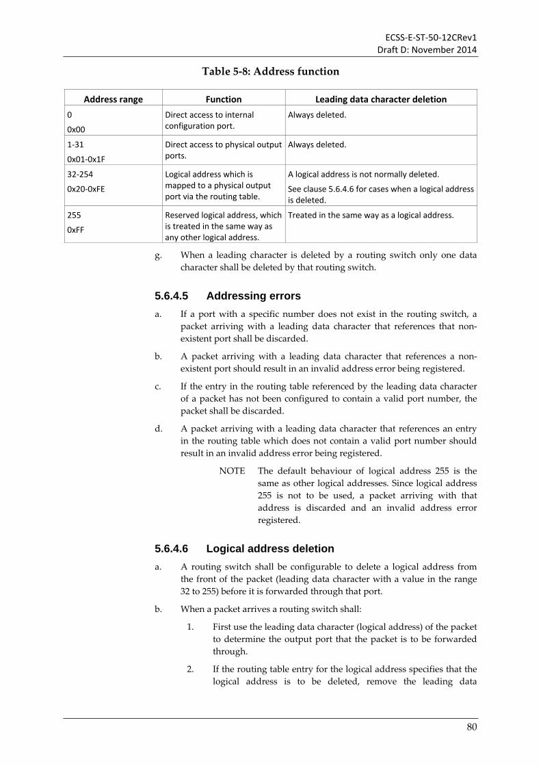
ECSS-E-ST-50-12CRev1 Draft D: November 2014
Table 5-8: Address function
Address range Function Leading data character deletion 0
0x00
Direct access to internal configuration port.
Always deleted.
1-31
0x01-0x1F
Direct access to physical output ports.
Always deleted.
32-254
0x20-0xFE
Logical address which is mapped to a physical output port via the routing table.
A logical address is not normally deleted.
See clause 5.6.4.6 for cases when a logical address is deleted.
255
0xFF
Reserved logical address, which is treated in the same way as any other logical address.
Treated in the same way as a logical address.
g. When a leading character is deleted by a routing switch only one data character shall be deleted by that routing switch.
5.6.4.5 Addressing errors a. If a port with a specific number does not exist in the routing switch, a
packet arriving with a leading data character that references that non-existent port shall be discarded.
b. A packet arriving with a leading data character that references a non-existent port should result in an invalid address error being registered.
c. If the entry in the routing table referenced by the leading data character of a packet has not been configured to contain a valid port number, the packet shall be discarded.
d. A packet arriving with a leading data character that references an entry in the routing table which does not contain a valid port number should result in an invalid address error being registered.
NOTE The default behaviour of logical address 255 is the same as other logical addresses. Since logical address 255 is not to be used, a packet arriving with that address is discarded and an invalid address error registered.
5.6.4.6 Logical address deletion a. A routing switch shall be configurable to delete a logical address from
the front of the packet (leading data character with a value in the range 32 to 255) before it is forwarded through that port.
b. When a packet arrives a routing switch shall:
1. First use the leading data character (logical address) of the packet to determine the output port that the packet is to be forwarded through.
2. If the routing table entry for the logical address specifies that the logical address is to be deleted, remove the leading data
80

ECSS-E-ST-50-12CRev1 Draft D: November 2014
character, exposing another logical address or path address at the front of the packet.
3. Forward the packet through the allocated port.
NOTE The deletion of a logical address is used to expand the number of nodes that can be accessed using logical addressing. A large network is divided into regions where a logical address applies. When crossing a region the logical address is deleted exposing a new logical address that applies to the next region. Regions using logical addressing can be connected to regions using path addressing.
5.6.4.7 Wormhole routing a. When a packet arrives at a routing switch the output port that it is to be
routed through shall be determined and allocated to that input port.
b. If the allocated output port is able to accept the start of another packet, the input port shall be connected to the output port so that the packet arriving at the input port is forwarded through the output port.
c. As each N-Char of the packet arrives at the input port it shall be transferred to the output port it is connected to for transmission.
d. An output port shall not transmit any other packet until the packet that it is currently transmitting has finished being sent or terminated following an error.
e. If an input port is waiting for packet characters to arrive, the output port that it is connected to shall also wait.
f. If an output port is waiting to transmit packet characters, i.e. waiting for FCTs to arrive to indicate that there is space in the input port at the far end of the link, the input port it is connected to shall also wait.
g. If the allocated output port is busy, the newly arrived packet shall wait at the input port until the allocated output port is free to transmit the new packet.
h. When the output port finishes transmission of a packet, it shall be available to accept a packet from another input port.
5.6.4.8 Arbitration a. When two or more input ports have been allocated to the same output
port and that output port has just finished sending a packet, the two or more input ports shall compete for connection to the output port.
b. The routing switch shall arbitrate between the two or more input ports competing for access to an output port and decide which input port is to be connected to the output port and send the next packet through it.
c. When the allocated output port becomes free, the input port connected to it after arbitration shall transfer one packet to the output port and then free the output port for subsequent arbitration and use by the same or another input port.
81

ECSS-E-ST-50-12CRev1 Draft D: November 2014
5.6.4.9 Group adaptive routing a. Group adaptive routing shall be optional in a routing switch.
b. A routing switch that supports group adaptive routing shall be able to route a packet with a logical address to one of several ports which is known as group adaptive routing.
c. A routing switch that supports group adaptive routing shall:
1. Have entries for each logical address in the routing table which specify one or more output ports that a packet with that logical address is able to be routed to.
2. Route a packet arriving with a leading data character that is a logical address to the lowest number port from the set of ports specified in the routing table that is currently free, i.e. not currently being used to send a packet.
3. When all of the set of output ports specified for a logical address are currently sending packets, arbitrate between all the input ports waiting to use the specified output ports as each of these output ports becomes free.
4. When an input port wins the arbitration, connect it to the output port that it competed for.
5.6.4.10 Packet multicast a. Packet multicast (sending of a particular packet to several destinations)
shall be optional in a source node, i.e. it is not necessary for a source node to implement packet multicast.
NOTE Packet multicasting is to be used with extreme care as it introduces many new ways to block or deadlock sections of the network.
b. Packet multicast in a routing switch shall be optional, i.e. it is not necessary for a routing switch to implement packet multicast.
c. A routing switch that supports packet multicast shall provide that support as follows:
1. The routing table in the routing switch shall be configurable to specify the set of ports (multicast set) that a packet with a particular logical address is to be concurrently sent through.
2. When a packet arrives with a logical address that is configured for multicast, the packet is sent to each of the output ports in the multicast set.
3. The packet to be multicast is sent to the designated output ports only when all of them are ready to accept a new packet.
4. If one or more of the output ports in the multicast set is not ready, all the output ports wait and the packet is not sent to any of the multicast output ports until they are all ready.
82
ECSS-E-ST-50-12CRev1 Draft D: November 2014
5.6.4.11 Router reset a. On reset of a routing switch the following shall occur:
1. All ports are reset.
2. Entries in the routing table for all logical addresses are set to not valid, so that a packet arriving with that logical address will be discarded, until the corresponding entry in the routing table is configured.
3. Group adaptive routing is disabled.
4. Packet multicast is disabled.
5.6.4.12 Port time-out a. A configurable port time-out shall be provided in the routing switch
which is used by all ports to detect a packet that has become stuck.
b. A separate configurable port time-out may be used for each port.
c. A packet shall be regarded by a port as being stuck when the following conditions are all fulfilled:
1. It has started, i.e. the first data character of the packet has been passed to the output port.
2. It has not yet ended, i.e. the EOP or EEP for that packet has not yet been passed to the output port.
3. The time since the last data character was sent from the input port to the output port is longer than the port time-out period.
d. When a packet is stuck the following actions shall be taken to clear the stuck packet:
1. The packet currently being sent is discarded.
2. An EEP is sent to the Encoding Layer.
NOTE i.e. the EEP is sent to the output port.
3. A stuck packet error condition should be registered so that the fact that it has occurred can be read via the router configuration port.
e. It shall be possible to disable the port time-out so that it does not time-out when a packet is stuck.
5.6.5 SpaceWire network a. A SpaceWire network shall comprise two or more nodes and zero or
more routing switches interconnected with SpaceWire links.
NOTE The UML diagram in Figure 5-29 illustrates the components of a SpaceWire network.
83

ECSS-E-ST-50-12CRev1 Draft D: November 2014
Node
Network
Routing SwitchLink
1..M 2..M 0..M
End Point
1..M
1..M
Switch Matrix
1
Routing Table
Port
Port Number
1
Connects
1
2
Config. Node
0..1
1..M
KEY
Association
1 or more
Made up of (aggregation)
Type of (specialisation)
EntityAttributes
Configures
Entity Name
SpaceWire Port
Figure 5-29: Components of a SpaceWire network
b. A SpaceWire network shall send packets from each source node to one or more destination nodes.
c. Packets from a source node shall travel across a SpaceWire link to a routing switch or the destination node.
d. Packets from a routing switch shall travel across SpaceWire links to other routing switches and to the destination node.
e. A SpaceWire network shall support broadcast of time-codes and distributed interrupt codes as an option, i.e. it is not necessary for a SpaceWire network to support time-codes and distributed interrupt codes.
f. For test purposes it should be possible to loop a port back on itself.
5.6.6 SpaceWire units and devices
5.6.6.1 SpaceWire units a. A SpaceWire unit shall comprise zero or more nodes and zero or more
routing switches.
b. A SpaceWire unit shall comprise at least one node or routing switch.
NOTE The components of a SpaceWire unit are illustrated in the UML diagram of Figure 5-30.
84

ECSS-E-ST-50-12CRev1 Draft D: November 2014
Unit
Instrument Processor
…0..M 0..M
Node Routing Switch Mass Memory
Figure 5-30: Components and specialisations of a SpaceWire unit
c. A SpaceWire unit shall contain an application which uses the services of a SpaceWire network.
NOTE Examples of a SpaceWire unit include a routing switch, an instrument with a SpaceWire interface, a processor with a SpaceWire interface and a mass memory with either an internal SpaceWire network connecting memory modules or external SpaceWire interfaces.
5.6.6.2 SpaceWire devices a. A SpaceWire device is a node or router with a device identifier.
b. The device identifier shall be configurable to uniquely identify the device on a network.
NOTE The specialisations of a SpaceWire device are illustrated in the UML diagram of Figure 5-31.
Device
Device ID
Node Routing Switch
Figure 5-31: Specialisations of a SpaceWire device
85

ECSS-E-ST-50-12CRev1 Draft D: November 2014
6 Service Interfaces
In this section the service interfaces for the services provided by each of the SpaceWire protocol layers are specified.
6.1 Network layer service interface a. The Network layer shall be responsible for the transfer of application
information over a SpaceWire network using three services: a Packet Transfer Service, a Time-Code Service and a Distributed Interrupt Service.
b. The Packet Transfer Service shall be used to send and receive SpaceWire packets over the SpaceWire network.
c. The Time-Code Service shall be used to broadcast time-codes across the network and to receive time-codes.
d. The Distributed Interrupt Service shall be used to broadcast interrupts across the network and to receive interrupts.
6.1.1 Packet service interface The service primitives that shall be associated with the SpaceWire packet service are:
SEND_PACKET.request; READ_PACKET.indication;
6.1.1.1 SEND_PACKET.request
6.1.1.1.1 Function The SEND_PACKET.request primitive shall be used to send a SpaceWire packet across a SpaceWire network.
6.1.1.1.2 Semantics The SEND_PACKET.request primitive shall provide the following parameters:
SEND_PACKET.request (End Point, SpaceWire Packet)
6.1.1.1.3 When Generated When the user has a packet to send over the SpaceWire network, it shall generate a SEND_PACKET.request primitive to request to send the SpaceWire packet over the network.
86

ECSS-E-ST-50-12CRev1 Draft D: November 2014
6.1.1.1.4 Effect On Receipt On receipt of the SEND_PACKET.request primitive the SpaceWire end point receiving the request shall send the SpaceWire packet though its port.
6.1.1.2 READ_PACKET.indication
6.1.1.2.1 Function A SpaceWire end point receiving a SpaceWire packet shall pass a READ_PACKET.indication primitive to the Read SpaceWire Packet service user to indicate that a SpaceWire packet has arrived at the end point and is waiting to be read.
6.1.1.2.2 Semantics The READ_PACKET.indication primitive provides parameters as follows:
READ_PACKET.indication (End Point, SpaceWire Packet).
6.1.1.2.3 When Generated The READ_PACKET.indication primitive shall be passed to the Read Packet service user when a SpaceWire packet is received.
6.1.1.2.4 Effect On Receipt The effect on receipt of the RX_PACKET.indication primitive by the Read Packet service user shall be that the service user reads the received SpaceWire packet.
6.1.2 Time-code service interface The service primitives that shall be associated with the time-code service are:
TIME-CODE.request; TIME-CODE.indication;
6.1.2.1 TIME-CODE.request
6.1.2.1.1 Function The TIME-CODE.request primitive shall be used by the SpaceWire user to request a SpaceWire end point to broadcast a time-code over the SpaceWire network.
6.1.2.1.2 Semantics The TIME-CODE.request primitive shall provide the following parameters:
TIME-CODE.request (End Point, Time-code value).
6.1.2.1.3 When Generated When the SpaceWire user wants to broadcast a time-code it shall generate a TIME-CODE.request primitive to request a SpaceWire end point to send the time-code through its SpaceWire port.
6.1.2.1.4 Effect On Receipt On receipt of the TIME-CODE.request primitive the SpaceWire end point shall immediately send the time-code through its port.
87

ECSS-E-ST-50-12CRev1 Draft D: November 2014
6.1.2.2 TIME-CODE.indication
6.1.2.2.1 Function The function of the TIME-CODE.indication primitive shall be to indicate to the SpaceWire user that a valid time-code has arrived at an end point.
6.1.2.2.2 Semantics The TIME-CODE.indication primitive provides parameters as follows:
TIME-CODE.indication (End Point, Time-code value)
6.1.2.2.3 When Generated The TIME-CODE.indication primitive shall be passed to the SpaceWire user, when a valid time-code is received.
6.1.2.2.4 Effect On Receipt The effect on receipt of the TIME-CODE.indication primitive by the SpaceWire user shall depend upon the application.
6.1.3 Distributed interrupt service interface The service primitives that shall be associated with the distributed interrupt service are:
DISTRIBUTED_INTERRUPT_READY.indication; DISTRIBUTED_INTERRUPT.request; DISTRIBUTED_INTERRUPT.indication; DISTRIBUTED_INTERRUPT_CLR.indication.
6.1.3.1 DISTRIBUTED_INTERRUPT_READY.indication
6.1.3.1.1 Function The function of the DISTRIBUTED_INTERRUPT_READY.indication primitive shall be to indicate to the SpaceWire user that the SpaceWire Network layer is ready to accept another distributed interrupt for broadcasting.
6.1.3.1.2 Semantics The DISTRIBUTED_INTERRUPT_READY.indication primitive provides parameters as follows:
DISTRIBUTED_INTERRUPT_READY.indication (End Point, Interrupt Identifier)
6.1.3.1.3 When Generated The DISTRIBUTED_INTERRUPT_READY.indication primitive shall be passed to the SpaceWire user, when the end point is ready to send a particular interrupt.
6.1.3.1.4 Effect On Receipt The effect on receipt of the DISTRIBUTED_INTERRUPT_READY.indication primitive by the SpaceWire user shall be for the SpaceWire user to generate a DISTRIBUTED_INTERRUPT.request for a specific interrupt (specific interrupt identifier value) when it wants to broadcast one.
88

ECSS-E-ST-50-12CRev1 Draft D: November 2014
6.1.3.2 DISTRIBUTED_INTERRUPT.request
6.1.3.2.1 Function The DISTRIBUTED_INTERRUPT.request primitive shall be used by the SpaceWire user to request a SpaceWire end point to send a distributed interrupt over the SpaceWire network.
6.1.3.2.2 Semantics The DISTRIBUTED_INTERRUPT.request primitive shall provide the following parameters:
DISTRIBUTED_INTERRUPT.request (End Point, Interrupt Identifier).
6.1.3.2.3 When Generated When the SpaceWire user has a distributed interrupt to send it shall generate a DISTRIBUTED_INTERRUPT.request primitive to request a SpaceWire end point to send the distributed interrupt.
6.1.3.2.4 Effect On Receipt On receipt of the DISTRIBUTED_INTERRUPT.request primitive the SpaceWire end point shall immediately send the distributed interrupt through its port.
6.1.3.3 DISTRIBUTED_INTERRUPT.indication
6.1.3.3.1 Function The function of the DISTRIBUTED_INTERRUPT.indication primitive shall be to indicate to the SpaceWire user that a distributed interrupt has arrived at an end point.
6.1.3.3.2 Semantics The DISTRIBUTED_INTERRUPT.indication primitive provides parameters as follows:
DISTRIBUTED_INTERRUPT.indication (End Point, Interrupt Identifier)
6.1.3.3.3 When Generated The DISTRIBUTED_INTERRUPT.indication primitive shall be passed to the SpaceWire user, when a valid distributed interrupt is received.
6.1.3.3.4 Effect On Receipt The effect on receipt of the DISTRIBUTED_INTERRUPT.indication primitive by the SpaceWire user shall depend upon the application.
6.1.3.4 DISTRIBUTED_INTERRUPT_CLR.indication
6.1.3.4.1 Function The function of the DISTRIBUTED_INTERRUPT_CLR.indication primitive shall indicate to the SpaceWire user that a distributed interrupt has been acknowledged.
6.1.3.4.2 Semantics The DISTRIBUTED_INTERRUPT_CLR.indication primitive provides parameters as follows:
DISTRIBUTED_INTERRUPT_CLR.indication (End Point, Interrupt Identifier)
89
ECSS-E-ST-50-12CRev1 Draft D: November 2014
6.1.3.4.3 When Generated The DISTRIBUTED_INTERRUPT_CLR.indication primitive shall be passed to the SpaceWire user, when a valid distributed interrupt acknowledgement is received.
6.1.3.4.4 Effect On Receipt The effect on receipt of the DISTRIBUTED_INTERRUPT_CLR.indication primitive by the SpaceWire user shall depend upon the application.
6.2 Data link layer service interface In this section the services provided by the SpaceWire data link layer to the SpaceWire network layer are specified.
6.2.1 N-Char service interface The service primitives that shall be associated with the N-Char service are:
SEND_READY.indication; SEND_NCHAR.request; READ_READY.indication; READ_NCHAR.request;
6.2.1.1 SEND_READY.indication
6.2.1.1.1 Function The SEND_READY.indication primitive shall be used to indicate that the data link layer has a port that is ready to accept another N-Char for sending across its link.
6.2.1.1.2 Semantics The SEND_READY.indication primitive shall provide the following parameters:
SEND_READY.indication (Port)
6.2.1.1.3 When Generated When the SpaceWire data link layer has a port that has room to accept another N-Char for sending over a SpaceWire link, it shall generate a SEND_READY.indication.
6.2.1.1.4 Effect On Receipt On receipt of the SEND_READY.indication primitive the SpaceWire port receiving the request shall make a SEND_NCHAR.request when it has an N-Char to send over the port that is ready to accept another N-Char.
6.2.1.2 SEND_NCHAR.request
6.2.1.2.1 Function The SEND_NCHAR.request primitive shall be used to send an N-Char through a port across a link.
6.2.1.2.2 Semantics The SEND_NCHAR.request primitive shall provide the following parameters:
SEND_NCHAR.request (Port, N-Char)
90

ECSS-E-ST-50-12CRev1 Draft D: November 2014
6.2.1.2.3 When Generated When the SpaceWire network layer has an N-Char to send over through a particular port and the data link layer has indicated that the port is ready to accept another N-Char, it shall generate a SEND_NCHAR.request primitive to request to load the N-Char into the port for sending over the link.
6.2.1.2.4 Effect On Receipt On receipt of the SEND_NCHAR.request primitive the SpaceWire port receiving the request shall send the N-Char provided that the link is in the Run state.
6.2.1.3 READ_READY.indication
6.2.1.3.1 Function A port that has received an N-Char shall generate a READ_READY.indication primitive to indicate to the network layer that an N-Char has arrived at the port and is waiting to be read.
6.2.1.3.2 Semantics The READ_READY.indication primitive provides parameters as follows:
READ_READY.indication (Port).
6.2.1.3.3 When Generated The READ_READY.indication primitive shall be passed to the network layer when an N-Char is in a port waiting to be read.
6.2.1.3.4 Effect On Receipt The effect on receipt of the RX_PACKET.indication primitive by the Network layer is that the Network layer shall read the received N-Char from the specified port.
6.2.1.4 READ_NCHAR.request
6.2.1.4.1 Function The READ_NCHAR.request primitive shall be used to read an N-Char received by a port.
6.2.1.4.2 Semantics The READ_NCHAR.request primitive provides parameters as follows:
READ_NCHAR.request (N-Char).
6.2.1.4.3 When Generated When the data link layer has indicated that a port has an N-Char ready to read and the network layer is ready to read an N-Char from that port, it shall generate a READ_NCHAR.request primitive to request to read the received N-Char from the port.
6.2.1.4.4 Effect On Receipt The effect on receipt of the READ_NCHAR.request primitive by the data link layer shall be that an N-Char from the specified port shall be read by the network layer.
6.2.2 Broadcast code service interface The service primitives that shall be associated with the BROADCAST_CODE service are:
91

ECSS-E-ST-50-12CRev1 Draft D: November 2014
BROADCAST_CODE.request; BROADCAST_CODE.indication;
6.2.2.1 BROADCAST_CODE.request
6.2.2.1.1 Function The BROADCAST_CODE.request primitive shall be used by the network layer to request a port to broadcast a broadcast code over the SpaceWire network.
6.2.2.1.2 Semantics The BROADCAST_CODE.request primitive shall provide the following parameters:
BROADCAST_CODE.request (Port, Broadcast code value).
6.2.2.1.3 When Generated When the network layer wants to send a broadcast code through a port it shall generate a BROADCAST_CODE.request primitive to request the port to send the broadcast code.
6.2.2.1.4 Effect On Receipt On receipt of the BROADCAST_CODE.request primitive the port shall send the broadcast code immediately after the character current has finished being sent.
6.2.2.2 BROADCAST_CODE.indication
6.2.2.2.1 Function The function of the BROADCAST_CODE.indication primitive shall be to indicate to the network layer that a broadcast code has arrived at a port.
6.2.2.2.2 Semantics The BROADCAST_CODE.indication primitive provides parameters as follows:
BROADCAST_CODE.indication (Port, Broadcast code value)
6.2.2.2.3 When Generated The BROADCAST_CODE.indication primitive shall be passed to the network layer, when the broadcast code is received.
6.2.2.2.4 Effect On Receipt The effect on receipt of the BROADCAST_CODE.indication primitive by the network layer shall be for the network layer to validate the broadcast code and forward it to the host system attached to an end point or broadcast it through all other ports of a routing switch.
6.3 Encoding layer service interface In this section the services provided by the encoding layer to the data link layer are specified.
6.3.1 Encoding service interface The service primitives that shall be associated with the encoding service are:
TX_CHAR.request;
92

ECSS-E-ST-50-12CRev1 Draft D: November 2014
TX_ENABLE.request.
6.3.1.1 TX_CHAR.request
6.3.1.1.1 Function The TX_CHAR.request primitive shall be used by the data link layer to send a character through its output port.
6.3.1.1.2 Semantics The TX_CHAR.request primitive shall provide the following parameters:
TX_CHAR.request (Character).
6.3.1.1.3 When Generated When the data link layer wants to send a character through its output port it shall generate a TX_CHAR.request primitive to encode the character, serialise it and send it through its output port.
6.3.1.1.4 Effect On Receipt On receipt of the TX_CHAR.request primitive the encoding layer shall encode the character, serialise it, data-strobe encode it, and pass it to the physical layer for driving across the physical medium to the receiver at the far end of the link.
6.3.1.2 TX_ENABLE.request
6.3.1.2.1 Function The TX_ENABLE.request primitive shall be used by the data link layer to request that the output port is enabled.
6.3.1.2.2 Semantics The TX_ENABLE.request primitive shall no paramenters:
TX_ ENABLE.request ().
6.3.1.2.3 When Generated When the data link layer wants to enable the output port so that it can make a connection and send data it shall generate a TX_ENABLE.request primitive.
6.3.1.2.4 Effect On Receipt On receipt of the TX_ENABLE.request primitive the encoding layer shall enable its output port.
6.3.1 Decoding service interface The service primitives that shall be associated with the decoding service are:
RX_CHAR.request; RX_ENABLE.request; DISCONNECT.indication RECEIVE_ERROR.indication; gotNULL.indication.
93

ECSS-E-ST-50-12CRev1 Draft D: November 2014
6.3.1.1 RX_CHAR.request
6.3.1.1.1 Function The RX_CHAR.request primitive shall be used by the data link layer to receive a character through its input port.
6.3.1.1.2 Semantics The RX_CHAR.request primitive shall provide the following parameters:
RX_CHAR.request.
6.3.1.1.3 When Generated When the data link layer wants to read a character from its input port it shall generate a RX_CHAR.request primitive to read the next character received by the input port.
6.3.1.1.4 Effect On Receipt On receipt of the RX_CHAR.request primitive the encoding layer shall pass a received, de-serialised and decoded character to the data link layer.
6.3.1.2 RX_ENABLE.request
6.3.1.2.1 Function The RX_ENABLE.request primitive shall be used by the data link layer to enable the input port to receive characters and control codes.
6.3.1.2.2 Semantics The RX_ENABLE.request primitive shall not have any parameters:
RX_ENABLE.request ().
6.3.1.2.3 When Generated When the data link layer wants to enable its input port it shall generate a RX_ENABLE.request primitive.
6.3.1.2.4 Effect On Receipt On receipt of the RX_ENABLE.request primitive the encoding layer shall enable its input port.
6.3.1.3 DISCONNECT.indication
6.3.1.3.1 Function The function of the DISCONNECT.indication primitive shall be to indicate to the data link layer that the SpaceWire link is disconnected.
6.3.1.3.2 Semantics The DISCONNECT.indication primitive provides no parameters:
DISCONNECT.indication ()
6.3.1.3.3 When Generated The DISCONNECT.indication primitive shall be passed to the data link layer, when the SpaceWire link becomes disconnected.
6.3.1.3.4 Effect On Receipt The effect on receipt of the DISCONNECT.indication primitive by the data link layer shall be for data link layer to move to the ErrorReset state.
94
ECSS-E-ST-50-12CRev1 Draft D: November 2014
6.3.1.4 RECEIVE_ERROR.indication
6.3.1.4.1 Function The function of the RECEIVE_ERROR.indication primitive shall be to indicate to the data link layer that an error has occurred in the receiver.
6.3.1.4.2 Semantics The RECEIVE_ERROR.indication primitive shall provide the following parameters:
RECEIVE_ERROR.indication (RX_Error_Flags)
Where the RX_Error_Flags indicate the type of error: parity error or ESC error.
6.3.1.4.3 When Generated The RECEIVE_ERROR.indication primitive shall be passed to the data link layer, when a receive error occurs.
6.3.1.4.4 Effect On Receipt The effect on receipt of the RECEIVE_ERROR.indication primitive by the data link layer shall be for data link layer to move to the ErrorReset state.
6.3.1.5 gotNULL.indication
6.3.1.5.1 Function The function of the gotNULL.indication primitive shall be to indicate to the data link layer that a Null has been received.
6.3.1.5.2 Semantics The gotNULL.indication primitive shall not provide any parameters:
gotNULL.indication ()
6.3.1.5.3 When Generated The gotNULL.indication primitive shall be passed to the data link layer, when the first Null is received after reset without any errors.
6.3.1.5.4 Effect On Receipt The effect on receipt of the gotNULL.indication primitive by the data link layer shall be according to the state machine of clause 5.5.7.
6.4 Physical layer service interface In this section the services provided by the physical layer to the encoding layer are specified.
6.4.1 Line transmit service interface The service primitives that shall be associated with the line transmit service are:
DS_TX.request.
95
ECSS-E-ST-50-12CRev1 Draft D: November 2014
6.4.1.1 DS_TX.request
6.4.1.1.1 Function The DS_TX.request primitive shall be used by the encoding layer to drive the data and strobe signals on to the physical medium.
6.4.1.1.2 Semantics The DS_TX.request primitive shall provide the following parameters:
DS_TX.request (Data, Strobe).
6.4.1.1.3 When Generated When the encoding layer wants to drive the data and strobe signals over the physical medium, it shall generate a DS_TX.request primitive.
6.4.1.1.4 Effect On Receipt On receipt of the DS_TX.request primitive the physical layer shall drive the data and strobe signals over the physical medium to the line receiver at the far end of the link.
6.4.1 Line receive service interface The service primitives that shall be associated with the line receive service are:
DS_RX.request.
6.4.1.1 DS_RX.request
6.4.1.1.1 Function The DS_RX.request primitive shall be used by the encoding layer to receive data and strobe signals from the line receiver.
6.4.1.1.2 Semantics The DS_RX.request primitive shall provide the following parameters:
DS_RX.request.
6.4.1.1.3 When Generated When the encoding layer wants to read the data and strobe signals received over the physical medium by the line receiver, it shall generate a DS_RX.request primitive.
6.4.1.1.4 Effect On Receipt On receipt of the DS_RX.request primitive the physical layer shall pass the data and strobe signals received over the physical medium to the encoding layer.
96

ECSS-E-ST-50-12CRev1 Draft D: November 2014
Bibliography
ECSS-ST-S-00 ECSS system - Description, implementation and general requirements
ECSS-E-ST-50 Space engineering - Communications
ECSS-E-HB-50 Space engineering - Communications guidelines
ECSS-E-ST-40 Space engineering - Software
http://www.spacewire.esa.int SpaceWire website
97