future focus: spacefibre -...
TRANSCRIPT

Martin Suess Slide : 1
Future Focus: SpaceFibre
� SpaceWire 101
Future Focus: SpaceFibre
Martin Suess - European Space Agency
Steve Parkes - University of Dundee
Jaakko Toivonen – Patria Systems Oy
Martin Suess Slide : 2
Future Focus: SpaceFibre
� SpaceWire 101
Overview
• SpaceFibre Requirements
• Mixed SpaceWire – SpaceFibre networks
• Demonstrator Development
• SpaceFibre Codec
• SpaceFibre Optical Link Technology
• Conclusion
Martin Suess Slide : 3
Future Focus: SpaceFibre
� SpaceWire 101
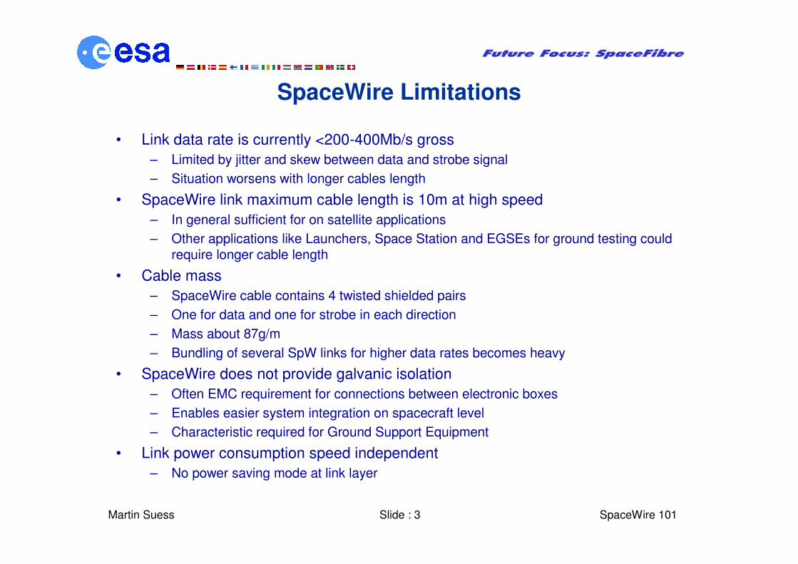
SpaceWire Limitations
• Link data rate is currently <200-400Mb/s gross
– Limited by jitter and skew between data and strobe signal
– Situation worsens with longer cables length
• SpaceWire link maximum cable length is 10m at high speed
– In general sufficient for on satellite applications
– Other applications like Launchers, Space Station and EGSEs for ground testing could require longer cable length
• Cable mass
– SpaceWire cable contains 4 twisted shielded pairs
– One for data and one for strobe in each direction
– Mass about 87g/m
– Bundling of several SpW links for higher data rates becomes heavy
• SpaceWire does not provide galvanic isolation
– Often EMC requirement for connections between electronic boxes
– Enables easier system integration on spacecraft level
– Characteristic required for Ground Support Equipment
• Link power consumption speed independent
– No power saving mode at link layer
Martin Suess Slide : 4
Future Focus: SpaceFibre
� SpaceWire 101
SpaceWire Features to be maintained
• Simplicity
• Low gate count and memory implementation
• Worm hole routing
• Bi-directional, full-duplex
• Group adaptive routing
• Bandwidth sharing
• Fault detection
• Time code distribution
Martin Suess Slide : 5
Future Focus: SpaceFibre
� SpaceWire 101
SpaceFibre Requirements
• Provide symmetrical, bi-directional, point to point link connection
• Handle data rates 1-10Gb/s and support variable signalling rates
• Bridge distances up to 100m at maximum data rate
• Be based on fibre optic link technology which provides galvanic isolation
• Copper version with AC coupling for shorter distances
• Allow for mixed SpaceWire – SpaceFibre networks via special SpaceWire-
SpaceFibre Routers
• Transmit a scalable number of virtual SpaceWire links over one SpaceFibre
• Compliant to the protocols and routing mechanisms defined in the SpaceWire
standard
• Similar bit error rates as specified for SpaceWire
• Fast start up and fine grained power management
• Intrinsic support to quality of service

Martin Suess Slide : 6
Future Focus: SpaceFibre
� SpaceWire 101
Mixed SpaceWire – SpaceFibre Router & Networks
• Transfer speed in network is determined by slowest link on the path
• SpaceFibre must not be slowed down by SpaceWire Link in network
• Concept: Several virtual SpaceWire Links over one SpaceFibre
– Multiplexing of data streams is required
– This can be performed on character or frame level
– Frame level multiplexing is preferred for a higher level of flexibility
SpaceWire - SpaceFibre Router BSpaceWire - SpaceFibre Router A
SpaceFibre
Port 1
Deserializ
er
SpW
Port 1
SpW
Port 2
SpWPort 3
SpW
Port 4
Non-blockingCrossbarSwitch
8B
10B
En
co
der
8B
10
B D
ec
od
er
Serializer
SpaceFibre
Port 2
SpaceFibre
Port 1
Deserializ
er
SpW
Port 1
SpW
Port 2
SpWPort 3
SpW
Port 4
Non-blockingCrossbarSwitch
8B
10B
En
co
der
8B
10
B D
eco
de
r
Serializer
SpaceFibre
Port 2
Co
din
g &
L
ink
Co
ntr
ol C
od
ing
& L
ink C
on
trol
Config.
Port
/
/Parallel
Port
Config.
Port
//Parallel
Port
Martin Suess Slide : 7
Future Focus: SpaceFibre
� SpaceWire 101
SpaceFibre Prototyping Activities
• Prototyping performed by two teams
• Covering complementary areas:
– SpaceFibre physical layer
– SpaceFibre Codec
• Two parallel development contracts
– “Optical Links for the Space Wire Intra Satellite Network Standard“
Objective: The development of a high speed point to point fibre optic link for space applications.
Contractors: Patria (Prime), VTT, INO, Fibre Pulse, W.L. Gore
– “Space Fibre” The TOPNET Call Off No. 2
Objective: Codec development and SpaceFibre integration into the Space Wire network through the development of a high speed router.
Contractor: University of Dundee
Martin Suess Slide : 8
Future Focus: SpaceFibre
� SpaceWire 101
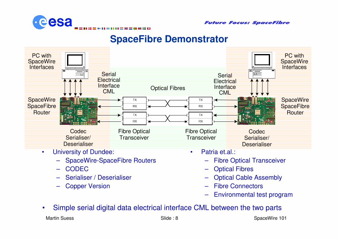
SpaceFibre Demonstrator
• University of Dundee:
– SpaceWire-SpaceFibre Routers
– CODEC
– Serialiser / Deserialiser
– Copper Version
Optical Fibres
PC withSpaceWireInterfaces
SerialElectricalInterface
CML
SerialElectricalInterface
CML
SpaceWireSpaceFibre
Router
SpaceWireSpaceFibre
Router
PC withSpaceWireInterfaces
Fibre OpticalTransceiver
Fibre OpticalTransceiver
CodecSerialiser/
Deserialiser
CodecSerialiser/
Deserialiser
• Patria et.al.:
– Fibre Optical Transceiver
– Optical Fibres
– Optical Cable Assembly
– Fibre Connectors
– Environmental test program
• Simple serial digital data electrical interface CML between the two parts
Martin Suess Slide : 9
Future Focus: SpaceFibre
� SpaceWire 101
SpaceFibre CODEC
• A number of high speed serial link standards have been reviewed
– Fibre Channel,
– Serial ATA,
– PCI Express,
– Infiniband,
– Gigabit Ethernet,
– Hypertransport
• Proposed solution must ensure compliance with SpaceWire protocols and routing mechanisms
Martin Suess Slide : 10
Future Focus: SpaceFibre
� SpaceWire 101
SpaceFibre CODEC Trade-off 1/5
• 8B/10B Encoding
– Gigabit Ethernet, Fibre Channel, PCI Express, Serial ATA and
Infiniband all use 8B/10B encoding
– Zero DC bias: same number of ones and zeros
– 1024 possibilities to encode 8-bit data characters + 16 control
characters
– Uses only codes with: 5 ones + 5 zeros, 4 ones + 6 zeros, 6 ones + 4 zeros
– Characters with uneven number of ones and zeros have two possible
encodings to preserve DC bias
– Running disparity determines which of two possible codes is used
– Control codes with unique seven bit comma sequence are used for
character alignment
– Ensures sufficient bit transitions – enabling for clock recovery with PLL
– No more than 5 consecutive ones or zeros
– Constant bit and character rate is simplifying decoding
Martin Suess Slide : 11
Future Focus: SpaceFibre
� SpaceWire 101
SpaceFibre CODEC Trade-off 2/5
• Ordered Sets
– Ordered Set concept of Fibre Channel, PCI Express, and Serial ATA
– Ordered Set is Comma Control Code followed by 3 bytes information
– Very attractive and powerful concept
– Enables transfer of link control information and other e.g. time-codes
• Scrambler
– Use of data scrambler to provide a spread spectrum signal
– Within PCI Express and Serial ATA
– To reduce the EM emissions from the copper version of SpaceFibre.
• Receive Elastic Buffer
– Required to compensate slight clock differences between transmitter and receiver
– Skip characters are inserted or removed to avoid congestion
– Reduces size of receive clock domain
– Simplifies circuitry and improves speed
Martin Suess Slide : 12
Future Focus: SpaceFibre
� SpaceWire 101
SpaceFibre CODEC Trade-off 3/5
• Byte Striping and Lanes
– PCI Express and Infiniband use byte striping across one or more lanes
– Extra lanes are added to increase the available bandwidth
– The group adaptive routing approach of SpaceWire is preferred
• Link Control
– Link initialisation
– Flow control
– Error detection and recovery
• Speed Negotiation Philosophy
– Link speed negotiation philosophy used by Serial ATA,
– Starting with the highest link speed first avoiding limitations with legacy
systems
– Is worth adopting for SpaceFibre
Martin Suess Slide : 13
Future Focus: SpaceFibre
� SpaceWire 101
SpaceFibre CODEC Trade-off 4/5
• Fine Grained Power Management
– Serial ATA provides for fine control of the power state of the
interface
– Two standby power states
– Specified in terms of the time that they take to recover
– Should be adopted for SpaceFibre.
• Soft Reset
– Serial ATA uses unexpected arrival of the SYNC character to reset
the interface.
– Effective mechanism for signalling severe error conditions
– A similar mechanism should be included in SpaceFibre
Martin Suess Slide : 14
Future Focus: SpaceFibre
� SpaceWire 101
SpaceFibre CODEC Trade-off 5/5
• Frames
– Nearly all of the standards examined use some sort of frame to
transfer data across a link
– Important if several channels are to be multiplexed over a single
link
– Especially when different quality of service provided
– Frames should be used in SpaceFibre
• Virtual Channels and Traffic Classes
– Virtual channels and traffic classes are powerful concepts defined
in the PCI Express standard
– Can be used to introduce quality of service at link layer
– The use of these concepts should be explored for SpaceFibre.
Martin Suess Slide : 15
Future Focus: SpaceFibre
� SpaceWire 101
SpaceFibre CODEC Trade Summary
• Use the lower level of Fibre Channel as the basis for SpaceFibre
– Bit and word synchronisation,
– 8B/10B encoding
– Ordered Sets.
• Elastic receive buffering compensates slight differences in clock speed
between units
• Scrambling of data and control codes should be included
• Link speed negotiation protocol should follow the highest-speed first
approach of Serial ATA
• Frame concept used in Fibre Channel, PCI Express and Serial ATA
should be adopted
• Fine grained power management of the link interfaces should be
supported
• Virtual channel and traffic class concepts similar to PCI Express should
be adopted.
Martin Suess Slide : 16
Future Focus: SpaceFibre
� SpaceWire 101
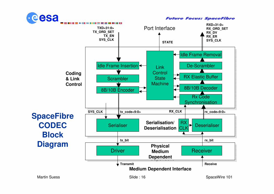
SpaceFibreCODECBlock
Diagram
LinkControlState
Machine8B/10B Decoder
Rx CodeSynchronisation
8B/10B Encoder
Serialisation/Deserialisation
Serialisation/Deserialisation
DeserialiserSerialiser
PhysicalMedium
Dependent
PhysicalMedium
Dependent
Coding& LinkControl
TXD<31:0>
TX_ORD_SET
TX_EN
SYS_CLK
tx_code<9:0> rx_code<9:0>
tx_bit rx_bit
RXD<31:0>
RX_ORD_SET
RX_DV
RX_ER
SYS_CLKSTATE
Transmit Receive
Medium Dependent Interface
RX Elastic Buffer
Driver Receiver
RXCLK
RX_CLKSYS_CLK
Port Interface
Idle Frame Insertion De-Scrambler
Idle Frame Removal
Scrambler
Martin Suess Slide : 17
Future Focus: SpaceFibre
� SpaceWire 101
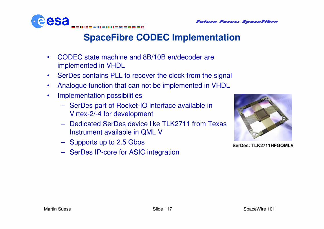
SpaceFibre CODEC Implementation
• CODEC state machine and 8B/10B en/decoder are
implemented in VHDL
• SerDes contains PLL to recover the clock from the signal
• Analogue function that can not be implemented in VHDL
• Implementation possibilities
– SerDes part of Rocket-IO interface available in
Virtex-2/-4 for development
– Dedicated SerDes device like TLK2711 from Texas
Instrument available in QML V
– Supports up to 2.5 Gbps
– SerDes IP-core for ASIC integrationSerDes: TLK2711HFGQMLV
Martin Suess Slide : 18
Future Focus: SpaceFibre
� SpaceWire 101
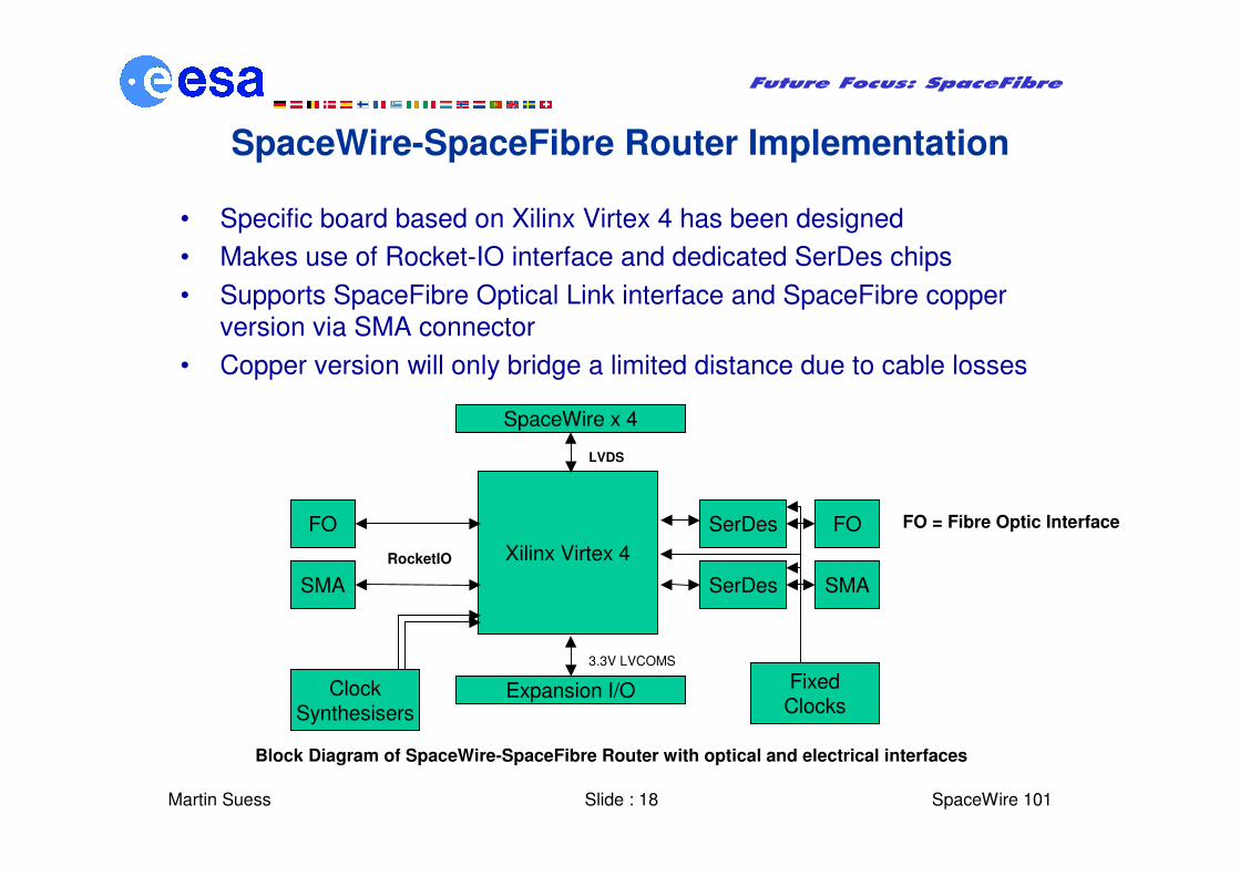
SpaceWire-SpaceFibre Router Implementation
• Specific board based on Xilinx Virtex 4 has been designed
• Makes use of Rocket-IO interface and dedicated SerDes chips
• Supports SpaceFibre Optical Link interface and SpaceFibre copper
version via SMA connector
• Copper version will only bridge a limited distance due to cable losses
Xilinx Virtex 4
SpaceWire x 4
Expansion I/O
SMA
FO
SMA
FO
SerDes
SerDes
LVDS
3.3V LVCOMS
RocketIO
ClockSynthesisers
FixedClocks
FO = Fibre Optic Interface
Block Diagram of SpaceWire-SpaceFibre Router with optical and electrical interfaces
Martin Suess Slide : 19
Future Focus: SpaceFibre
� SpaceWire 101
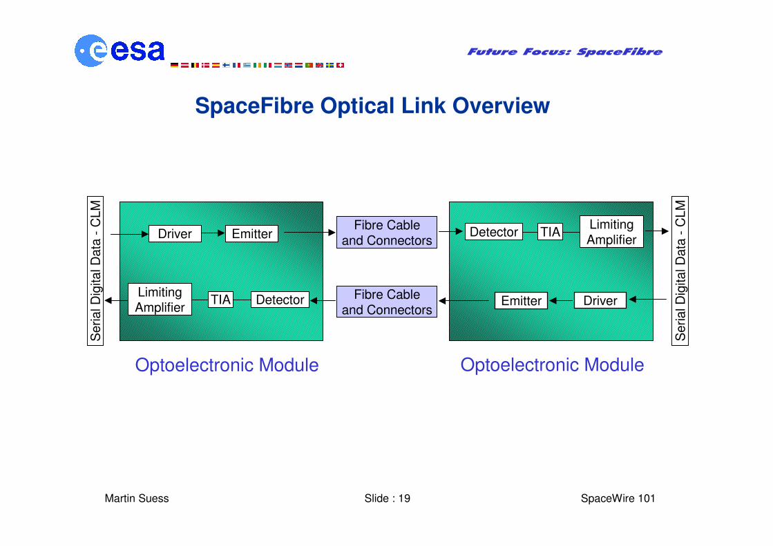
SpaceFibre Optical Link Overview
Driver Emitter
Emitter Driver
Fibre Cable and Connectors
Fibre Cable and Connectors
TIA
TIA
Detector
DetectorLimiting Amplifier
Limiting Amplifier
Serial D
igital D
ata
-C
LM
Serial D
igital D
ata
-C
LM
Optoelectronic Module Optoelectronic Module
Martin Suess Slide : 20
Future Focus: SpaceFibre
� SpaceWire 101
Transceiver Module Design 1/4
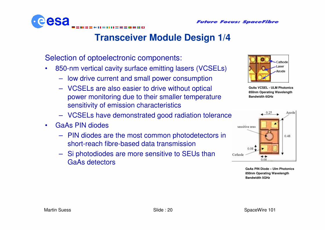
Selection of optoelectronic components:
• 850-nm vertical cavity surface emitting lasers (VCSELs)
– low drive current and small power consumption
– VCSELs are also easier to drive without optical
power monitoring due to their smaller temperature
sensitivity of emission characteristics
– VCSELs have demonstrated good radiation tolerance
• GaAs PIN diodes
– PIN diodes are the most common photodetectors in
short-reach fibre-based data transmission
– Si photodiodes are more sensitive to SEUs than
GaAs detectors
GsAs VCSEL - ULM Photonics
850nm Operating Wavelength
Bandwidth 6GHz
GaAs PIN Diode – Ulm Photonics
850nm Operating Wavelength
Bandwidth 5GHz
Martin Suess Slide : 21
Future Focus: SpaceFibre
� SpaceWire 101
Transceiver Module Design 2/4
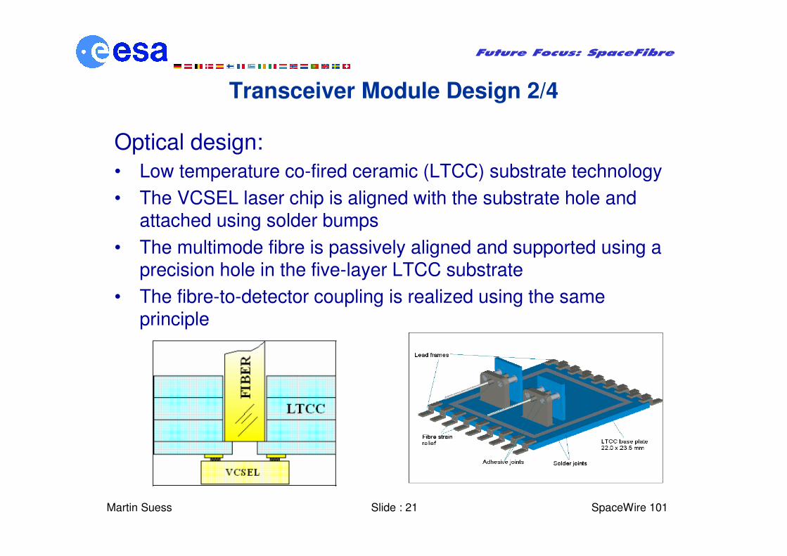
Optical design:
• Low temperature co-fired ceramic (LTCC) substrate technology
• The VCSEL laser chip is aligned with the substrate hole and attached using solder bumps
• The multimode fibre is passively aligned and supported using a precision hole in the five-layer LTCC substrate
• The fibre-to-detector coupling is realized using the same principle
Martin Suess Slide : 22
Future Focus: SpaceFibre
� SpaceWire 101
Transceiver Module Design 3/4
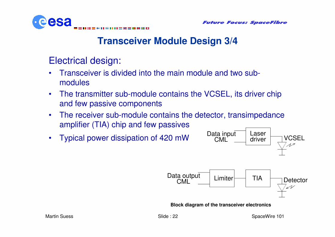
Electrical design:
• Transceiver is divided into the main module and two sub-modules
• The transmitter sub-module contains the VCSEL, its driver chip and few passive components
• The receiver sub-module contains the detector, transimpedanceamplifier (TIA) chip and few passives
• Typical power dissipation of 420 mWLaserdriver
Data inputCML VCSEL
TIAData outputCML DetectorLimiter
Block diagram of the transceiver electronics
Martin Suess Slide : 23
Future Focus: SpaceFibre
� SpaceWire 101
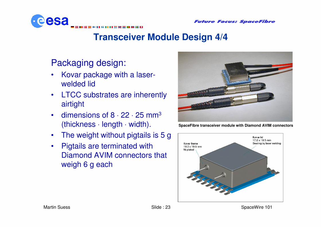
Transceiver Module Design 4/4
Packaging design:
• Kovar package with a laser-welded lid
• LTCC substrates are inherently airtight
• dimensions of 8 ⋅ 22 ⋅ 25 mm3
(thickness ⋅ length ⋅ width).
• The weight without pigtails is 5 g
• Pigtails are terminated with Diamond AVIM connectors that weigh 6 g each
SpaceFibre transceiver module with Diamond AVIM connectors
Martin Suess Slide : 24
Future Focus: SpaceFibre
� SpaceWire 101
SpaceFibre Environmental Requirements
• Several different missions were reviewed for identifying typicalrequirements to be used as the baseline for the SpaceFibre link specifications:
– Random vibration ≤ 25 grms
– Mechanical shock ≤ 3000 g @ 10 kHz
– Total radiation dose ≤ 100 krad
– Operational temperature −40 ... + 85 °C
– Storage temperature −50 ... + 95 °C
– Mission lifetime up to 15 years
– Non-outgassing materials
Martin Suess Slide : 25
Future Focus: SpaceFibre
� SpaceWire 101
Transceiver Module Testing 1/3
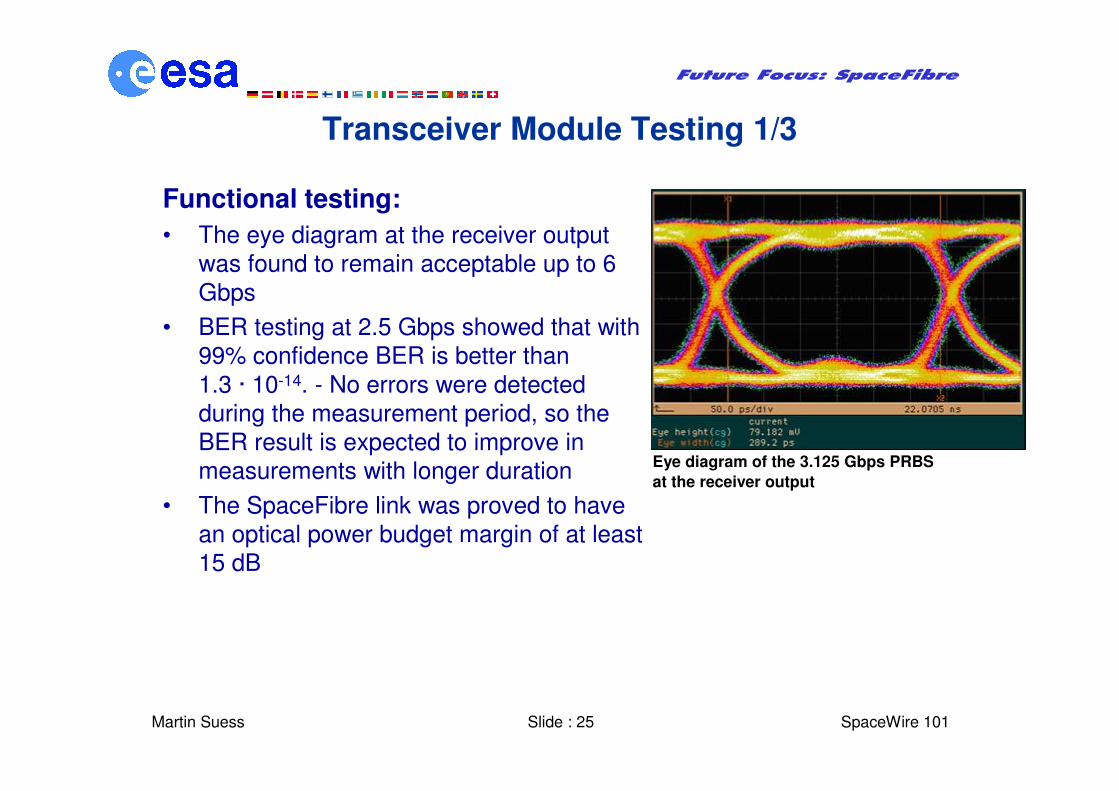
Functional testing:
• The eye diagram at the receiver output
was found to remain acceptable up to 6
Gbps
• BER testing at 2.5 Gbps showed that with
99% confidence BER is better than
1.3 · 10-14. - No errors were detected
during the measurement period, so the
BER result is expected to improve in
measurements with longer duration
• The SpaceFibre link was proved to have
an optical power budget margin of at least
15 dB
Eye diagram of the 3.125 Gbps PRBS
at the receiver output
Martin Suess Slide : 26
Future Focus: SpaceFibre
� SpaceWire 101
Transceiver Module Testing 2/3
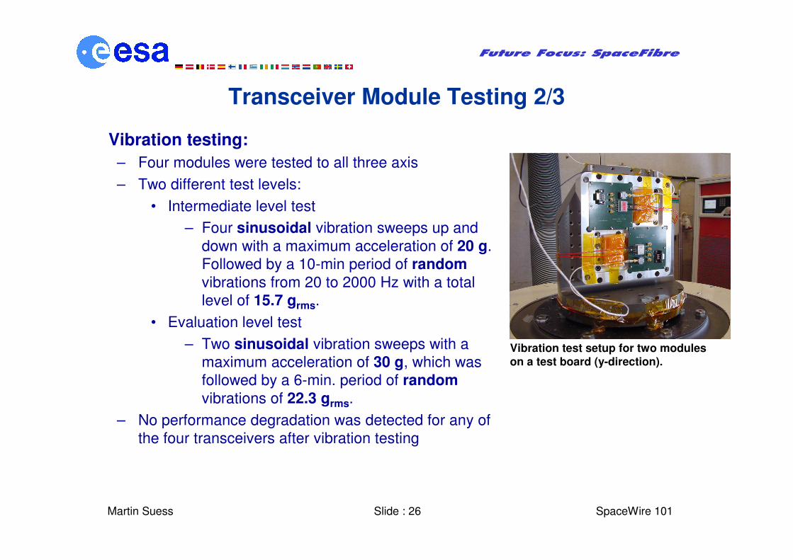
Vibration testing:
– Four modules were tested to all three axis
– Two different test levels:
• Intermediate level test
– Four sinusoidal vibration sweeps up and
down with a maximum acceleration of 20 g.
Followed by a 10-min period of random
vibrations from 20 to 2000 Hz with a total
level of 15.7 grms.
• Evaluation level test
– Two sinusoidal vibration sweeps with a
maximum acceleration of 30 g, which was
followed by a 6-min. period of random
vibrations of 22.3 grms.
– No performance degradation was detected for any of
the four transceivers after vibration testing
Vibration test setup for two moduleson a test board (y-direction).
Martin Suess Slide : 27
Future Focus: SpaceFibre
� SpaceWire 101
Transceiver Module Testing 3/3
Thermal cycling:
– Two modules were subjected to a test campaign of 2 x 40 cycles in
air circulating chamber from -40°C to +85°C.
– The average duration of min. and max. temperature levels for each
cycle was 15 minutes
– Modules were operational throughout the testing, transmitting BER
test data at 2.0 Gbps to both directions
– The maximum degradation of module power budget was in the
order of -4 dB at + 85°C.
– At -40°C the performance degradation was negligible
Radiation testing is ongoing but looks very promising
Shock testing:
– Three modules were tested to all three axis
– Impacts with peaks from 2900 to 3900 g were used
– All modules were found to be operational after the shock impacts.
– One module showed slight degradation in performance
Martin Suess Slide : 28
Future Focus: SpaceFibre
� SpaceWire 101
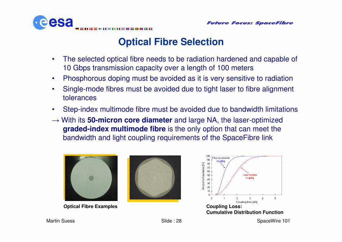
Optical Fibre Selection
• The selected optical fibre needs to be radiation hardened and capable of
10 Gbps transmission capacity over a length of 100 meters
• Phosphorous doping must be avoided as it is very sensitive to radiation
• Single-mode fibres must be avoided due to tight laser to fibre alignment
tolerances
• Step-index multimode fibre must be avoided due to bandwidth limitations
→ With its 50-micron core diameter and large NA, the laser-optimized
graded-index multimode fibre is the only option that can meet the
bandwidth and light coupling requirements of the SpaceFibre link
Optical Fibre Examples Coupling Loss:Cumulative Distribution Function
Martin Suess Slide : 29
Future Focus: SpaceFibre
� SpaceWire 101
Optical Fibre Testing
• Radiation can introduce darkening of the fibre
• Radiation hardness of several COTS laser-optimized graded-index multimode fibres were determined
• Measurements of the radiation-induced attenuation show losses varying from 7 to 16 dB when the 100 m long fibres are exposed to a dose rate of 45 krad/h and for a total irradiation dose of 100 krad
• When considering the typical dose rates in space, radiation-induced attenuation losses can be as low as 0.05 to 1 dB
• Draka MaxCap 300 radhard-optimized fibre, the best performing fibre was selected for the SpaceFibre link
Martin Suess Slide : 30
Future Focus: SpaceFibre
� SpaceWire 101
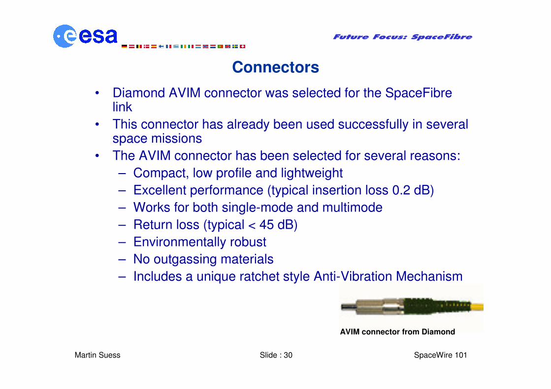
Connectors
• Diamond AVIM connector was selected for the SpaceFibre link
• This connector has already been used successfully in several space missions
• The AVIM connector has been selected for several reasons:
– Compact, low profile and lightweight
– Excellent performance (typical insertion loss 0.2 dB)
– Works for both single-mode and multimode
– Return loss (typical < 45 dB)
– Environmentally robust
– No outgassing materials
– Includes a unique ratchet style Anti-Vibration Mechanism
AVIM connector from Diamond
Martin Suess Slide : 31
Future Focus: SpaceFibre
� SpaceWire 101
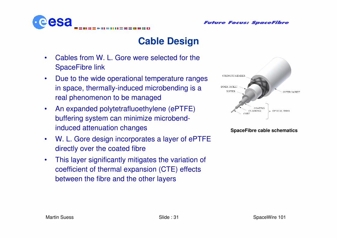
Cable Design
• Cables from W. L. Gore were selected for the
SpaceFibre link
• Due to the wide operational temperature ranges
in space, thermally-induced microbending is a
real phenomenon to be managed
• An expanded polytetrafluoethylene (ePTFE)
buffering system can minimize microbend-
induced attenuation changes
• W. L. Gore design incorporates a layer of ePTFE
directly over the coated fibre
• This layer significantly mitigates the variation of
coefficient of thermal expansion (CTE) effects
between the fibre and the other layers
SpaceFibre cable schematics
Martin Suess Slide : 32
Future Focus: SpaceFibre
� SpaceWire 101
Conclusions
• SpaceFibre was investigated as the fibre optical extension to the SpaceWire
standard
• SpaceFibre will be able to cover the very high data rate applications while being
in line with the SpaceWire developments
• The copper version of SpaceFibre is intended to cover shorter distances in
particular application areas
• System requirements together with CODEC and optical technology trades-offs
were presented
• CODEC and optical transceiver design where shown
• Environmental testing results for the optical technology where reported
• A demonstrator has been developed within the SpaceFibre activity to show a
mixed SpaceWire – SpaceFibre network
• The demonstrator can serve as test bed for a standardisation to be initiated in the
SpaceWire Working Group