spacewire handbookspacewire.esa.int/wg/spacewire/spw-wg-mtg19... · cooperation for space...
TRANSCRIPT
SpaceWire Handbook
DRAFT - SVN version 45 - September 24, 2012
4Links LimitedSuite E U 2
Bletchley ParkMilton Keynes, MK3 6EB
United Kingdom
Copyright © 2012 4Links Limited.
SpaceWire Handbook DRAFT - SVN version 45 - September 24, 2012
Foreword
This Draft Handbook is 4Links Limited’s initial contribution to the forthcoming ECSSSpaceWire Handbook.
Change Log
Date Version2012/06/29 Firstdraft issue2012/09/24 Seconddraft issue
Copyright © 2012 4Links Limited. 2
SpaceWire Handbook DRAFT - SVN version 45 - September 24, 2012
Table of Contents
Title Page . . . . . . . . . . . . . . . . . . . . . . . . . 1Foreword . . . . . . . . . . . . . . . . . . . . . . . . . 2Change Log . . . . . . . . . . . . . . . . . . . . . . . . 2
1. Intr oduction . . . . . . . . . . . . . . . . . . . . . . . 61.1. Purpose . . . . . . . . . . . . . . . . . . . . . . . 61.2. Scope . . . . . . . . . . . . . . . . . . . . . . . . 61.3. Acknowledgements . . . . . . . . . . . . . . . . . . . . 61.4. Documentstructure . . . . . . . . . . . . . . . . . . . . 7
2. Terms, definitions and abbreviations . . . . . . . . . . . . . . . 82.1. Terms and definitions from other documents. . . . . . . . . . . . 82.2. Terms specific to the present handbook. . . . . . . . . . . . . 8
2.2.1. SpaceWire End-Point. . . . . . . . . . . . . . . . . . 82.2.2. SpaceWire Node . . . . . . . . . . . . . . . . . . . 82.2.3. SpaceWire Unit . . . . . . . . . . . . . . . . . . . 8
2.3. Abbreviated terms . . . . . . . . . . . . . . . . . . . . 8
3. References. . . . . . . . . . . . . . . . . . . . . . . . 9
4. Intr oduction to SpaceWire . . . . . . . . . . . . . . . . . . 104.1. Backgroundand History . . . . . . . . . . . . . . . . . . 10
4.1.1. 1960- A Modular Computer . . . . . . . . . . . . . . . 104.1.2. 1980- System on Chip, Serial Interfaces . . . . . . . . . . . . 114.1.3. Transputer serial links in space. . . . . . . . . . . . . . . 114.1.4. Modularity . . . . . . . . . . . . . . . . . . . . . 124.1.5. 1990+Transputer links to IEEE-1355 . . . . . . . . . . . . 124.1.6. IEEE-1355and early SpaceWire in Space. . . . . . . . . . . 13
4.2. Thecurrent SpaceWire Standard. . . . . . . . . . . . . . . . 134.2.1. Data-Strobeencoding . . . . . . . . . . . . . . . . . . 144.2.2. Low-level flow-control . . . . . . . . . . . . . . . . . 154.2.3. Packets . . . . . . . . . . . . . . . . . . . . . . 154.2.4. Packet Routing. . . . . . . . . . . . . . . . . . . . 154.2.5. Time Codes and their distribution . . . . . . . . . . . . . . 164.2.6. SpaceWire in comparison with other communication techniques. . . . 16
4.2.6.1. Asynchronousand Synchronous Serial Communications. . . . . 164.2.6.2. MIL-STD-1553B . . . . . . . . . . . . . . . . . 174.2.6.3. CANbus . . . . . . . . . . . . . . . . . . . . 174.2.6.4. Ethernet . . . . . . . . . . . . . . . . . . . . 184.2.6.5. OpticalFibre . . . . . . . . . . . . . . . . . . . 19
4.2.7. WhereSpaceWire is being used. . . . . . . . . . . . . . 194.3. TheFuture of SpaceWire . . . . . . . . . . . . . . . . . . 19
4.3.1. How the SpaceWire Standards will Develop . . . . . . . . . . 19
Copyright © 2012 4Links Limited. 3
SpaceWire Handbook DRAFT - SVN version 45 - September 24, 2012
4.3.2. How the use of SpaceWire will evolve . . . . . . . . . . . . 204.4. Summary. . . . . . . . . . . . . . . . . . . . . . . 21
5. ECSS-E-ST-50-12C and related standards . . . . . . . . . . . . . 225.1. ECSS-E-ST-50-12C : SpaceWire - Links, nodes, routers and networks . . . . 22
5.1.1. Commentaryon the SpaceWire Standard. . . . . . . . . . . 225.1.1.1. TheSpaceWire Physical Layer . . . . . . . . . . . . . 225.1.1.2. TheSpaceWire Signal Layer. . . . . . . . . . . . . . 235.1.1.3. TheSpaceWire Character Level . . . . . . . . . . . . . 245.1.1.4. TheSpaceWire Exchange Level . . . . . . . . . . . . . 255.1.1.5. TheSpaceWire Packet Level . . . . . . . . . . . . . . 275.1.1.6. TheSpaceWire Network Level . . . . . . . . . . . . . 27
5.1.2. SpaceWire Performance. . . . . . . . . . . . . . . . . 285.2. ECSS-E-ST-50-51C : SpaceWire Protocol Identification. . . . . . . . 295.3. ECSS-E-ST-50-52C : the Remote Memory Access Protocol. . . . . . . 29
5.3.1. Commentaryon the SpaceWire RMAP Standard. . . . . . . . . 295.4. ECSS-E-ST-50-53C : the CCSDS Packet Transfer Protocol. . . . . . . 30
6. SpecificImplementation Topics . . . . . . . . . . . . . . . . . 316.1. Physical Layer Interconnections. . . . . . . . . . . . . . . . 31
6.1.1. SpaceWire Binary Encoding . . . . . . . . . . . . . . . 316.1.2. LVDS Signals and Levels . . . . . . . . . . . . . . . . 316.1.3. SpaceWire codec implementation. . . . . . . . . . . . . . 32
6.1.3.1. Asynchronousissues at the logic level . . . . . . . . . . . 326.1.4. SpaceWire Cabling . . . . . . . . . . . . . . . . . . 326.1.5. Grounding . . . . . . . . . . . . . . . . . . . . . 336.1.6. PrintedCircuit Board layout . . . . . . . . . . . . . . . 336.1.7. OtherEMC Issues. . . . . . . . . . . . . . . . . . . 33
6.1.7.1. EMCMitigation through Token Randomisation. . . . . . . . 336.1.7.2. EMCMitigation through Bit Rate Randomisation. . . . . . . 34
6.2. ReducingJitter in Time Codes / other places. . . . . . . . . . . . 346.3. SpaceWire Routing Issues. . . . . . . . . . . . . . . . . . 34
6.3.1. Wormhole Routing . . . . . . . . . . . . . . . . . . 346.3.2. Corruptionof the Routing Tables . . . . . . . . . . . . . . 35
6.4. SpaceWire network architectures . . . . . . . . . . . . . . . 366.4.1. Point-to-PointSerial Cable Replacement . . . . . . . . . . . 366.4.2. Chainedand Cyclic Configurations . . . . . . . . . . . . . 376.4.3. Mesh-ConnectedNetworks . . . . . . . . . . . . . . . . 386.4.4. Fully-ConnectedNetworks . . . . . . . . . . . . . . . . 386.4.5. RoutedNetworks . . . . . . . . . . . . . . . . . . . 39
6.4.5.1. SingleRouter Configurations. . . . . . . . . . . . . . 396.4.5.2. MultipleRouter Configurations - Making larger routers. . . . . 406.4.5.3. MultipleRouter Configurations - to increase routed bandwidth. . . 406.4.5.4. MultipleRouter Configurations - to provide redundancy . . . . . 406.4.5.5. MultipleRouter Configurations - Hybrid Networks . . . . . . . 416.4.5.6. Cube-connectedCycles [Hypercubes] . . . . . . . . . . . 42
Copyright © 2012 4Links Limited. 4
SpaceWire Handbook DRAFT - SVN version 45 - September 24, 2012
6.5. FDIR(Failure Detection, Isolation and Recovery) . . . . . . . . . . 426.5.1. Failure Detection . . . . . . . . . . . . . . . . . . . 436.5.2. Fault Isolation . . . . . . . . . . . . . . . . . . . . 446.5.3. Fault Recovery . . . . . . . . . . . . . . . . . . . . 44
6.6. Plug-and-Playconfiguration . . . . . . . . . . . . . . . . . 446.7. Backplanes . . . . . . . . . . . . . . . . . . . . . . 456.8. SpaceWire D vs Timed Ethernet. . . . . . . . . . . . . . . . 456.9. SpaceWire Verification and Validation . . . . . . . . . . . . . . 45
6.9.1. Testing the Physical and Signal Layers. . . . . . . . . . . . 466.9.2. Testing the Higher SpaceWire Protocol Layers. . . . . . . . . . 466.9.3. Testing Higher-level SpaceWire Protocols . . . . . . . . . . . 476.9.4. System-Level Testing . . . . . . . . . . . . . . . . . . 48
6.10. SpaceWire Limitations . . . . . . . . . . . . . . . . . . 486.11. LessonsLearned . . . . . . . . . . . . . . . . . . . . 48
7. SupportingComponents . . . . . . . . . . . . . . . . . . . 497.1. SpaceWire Circuits . . . . . . . . . . . . . . . . . . . . 49
7.1.1. Integrated Circuits. . . . . . . . . . . . . . . . . . . 497.1.2. IP(Intellectual Property) Cores . . . . . . . . . . . . . . 497.1.3. Boardsand spacecraft processors. . . . . . . . . . . . . . 49
7.2. SpaceWire Prototyping products. . . . . . . . . . . . . . . . 497.2.1. Bridgesand Gateways . . . . . . . . . . . . . . . . . 497.2.2. Routers . . . . . . . . . . . . . . . . . . . . . . 49
7.3. Test Equipment . . . . . . . . . . . . . . . . . . . . . 497.3.1. Electricalconformance / physical-layer compliance testers. . . . . . 497.3.2. Low-level protocol analysers . . . . . . . . . . . . . . . 497.3.3. Traffic Recorders . . . . . . . . . . . . . . . . . . . 49
8. Bibliography . . . . . . . . . . . . . . . . . . . . . . . 50
Copyright © 2012 4Links Limited. 5
SpaceWire Handbook DRAFT - SVN version 45 - September 24, 2012
1. Introduction
1.1. PurposeThis ECSS handbook is intended to help implementers and users of data handling systemswho are basing designs on the ECSS E-50 series of standards. The handbook provides anoverview of the E-50 standards and related CCSDS Recommended Standards and describeshow the individual standards may be used together to form a coherent set of communicationsprotocols. It also evaluates issues which could not be discussed in the Standards documentsthemselves, and provides guidance on option selection and implementation choices.
1.2. ScopeThis handbook provides guidance to the ECSS E-50 series of standards including relatedCCSDS Recommendations. The information provided is informative and is a guide to bestpractice; it is not binding on implementers.The information contained in this handbook is notpart of the ECSS Standards.
1.3. AcknowledgementsThis Handbook has been authored and agreed upon by the following persons:
A.N. Person, Organisation (physical layer)
A.N. Other, Second Organisation (routing switches)
This Handbook has been prepared based on volunteer contributions of the authors.
Copyright © 2012 4Links Limited. 6
SpaceWire Handbook DRAFT - SVN version 45 - September 24, 2012
1.4. Document structureThis document is divided into sections and annexes as follows:
• Section 1, “Introduction”, (this section) provides intentional and administrativeinformation.
• Section 2, “Terms, definitions and abbreviations”, provides the definition andabbreviations of the terms used in the present document.
• Section 3, “References”, provides a list of the E-50 series of ESA SpaceWire standards.
• Section 4, “Introduction to SpaceWire”, provides an introduction to SpaceWire itself.
• Section5, “ECSS-E-ST-50-12C and related standards”, provides detailed information oneach of the individual ECSS and CCSDS standards covered by the handbook.
• Section 6, “Specific Implementation Topics”, addresses individual technical topicsrelated to the ECSS E-50 standards.
• Section7, “Supporting Components”, provides a summary of supporting componentsand products.
• Section 8, “Bibliography”, lists the other references included in this Handbook.
Copyright © 2012 4Links Limited. 7
SpaceWire Handbook DRAFT - SVN version 45 - September 24, 2012
2. Terms, definitions and abbreviations
2.1. Terms and definitions from other documentsFor the purpose of this document, the terms and definitions from ECSS-E-ST-50-12C apply.
2.2. Terms specific to the present handbook
2.2.1. SpaceWire End-Point
A SpaceWire End-Point is a hardware or software process that connects to one or moreSpaceWire packet-level processes; a SpaceWire packet producer or consumer.
2.2.2. SpaceWire Node
A SpaceWire Node is the source or destination of a SpaceWire packet stream (i.e.a stream ofbytes or time-codes), which comprises one or more end-points.A node can therefore be aprocessor, a memory unit, a sensor, an EGSE, or some other unit connected to a SpaceWirenetwork.
2.2.3. SpaceWire Unit
A SpaceWire Unit is a box, board or subsystem, that can contain one or more SpaceWirenodes.
2.3. Abbreviated termsThe following abbreviated terms are used within this document:
Abbr eviation MeaningEX exampleEX exampleEX example
Copyright © 2012 4Links Limited. 8
SpaceWire Handbook DRAFT - SVN version 45 - September 24, 2012
3. ReferencesThis document is the handbook corresponding to the SpaceWire standard ECSS-E-ST-50-12Cand the subsidiary SpaceWire standards listed below.
The following normative documents are referenced in this text or provide additionalinformation useful for the reader.
ECSS-E-ST-50-12C SpaceWire - Links, nodes, routers and networks
ECSS-E-ST-50-51C SpaceWire protocol identification
ECSS-E-ST-50-52C SpaceWire - Remote memory access protocol
ECSS-E-ST-50-53C SpaceWire - CCSDS packet transfer protocol
These standards documents are available athttp://www.spacewire.esa.int.
Also, the following normative non-ESA documents are referenced:
ANSI / TIA / EIA-644 1995 Telecommunications Industry Association,“Electrical Characteristics of Low VoltageDifferential Signaling (LVDS) Interface Circuits”,March 1996
IEEE Standard for “(Low-Cost, Low-Latency ScalableHeterogeneous Interconnect Serial Interconnect for Parallel System
Construction)”,IEEE Standard 1355-1995,IEEE Computer Society,June 1996.
Copyright © 2012 4Links Limited. 9
SpaceWire Handbook DRAFT - SVN version 45 - September 24, 2012
4. Introduction to SpaceWireThis section outlines the background to the topics that are covered in greater depth later in thisHandbook. Muchof this material is drawn from [Walker 2003].
4.1. Background and HistorySpaceWire is a data communication technology that was standardised by ECSS (the EuropeanCooperation for Space Standardization) in January 2003 and re-issued as ECSS-E-ST-50-12Con 31 July 2008 [see section3, “References”, for information about the ESA SpaceWirestandards documents]. Early versions of SpaceWire are flying on several missions, and it isplanned for use on many missions worldwide. Asa simple interface that can be used for awide variety of different purposes, SpaceWire appears to offer an enabling technology for a“Building Block Architecture” such as described in NASA’s Vision for Space Exploration[NASA 2004], for rapid deployment, such as DoD’s PnPSat [McNutt 2009], and for costreduction as a result of architecture and subsystem re-use as practised by ESA.Whilestandardised in the 21st century, SpaceWire has evolved over many years, following a few keyprinciples and concepts that are the foundation of its wide application and use.
The following sections describe the evolution of SpaceWire and draw from it several keyprinciples and concepts.
4.1.1. 1960 - A Modular Computer
In the 1960s, a computer would be built from several different boxes, such as processor,memory, disc controller and communications controller. One way to connect the boxestogether was to use a simple standard interface between any of these boxes, so that they couldeach access the others independently of each other.
An example of this was the interface of the CTL Modular One computer. The key concepts ofthis standard interface were:
• Keep the bus inside each box, so that the whole system did not share a single bus;
• Use an asynchronous interface, so that each box could run at its optimum speed andthere was no need for global synchronisation;
• Use a symmetrical interface, so that any box could be connected to any box;
• Have flow-control across the interface so that data was not lost even if buffers were full(but this may have resulted in reduced performance if a communication was blocked).
These key principles resulted in a number of benefits:
• The system was scalable, so that systems could be built with any number of processors,memories, and peripherals;
• There were few constraints on the topology of the system, so that systems could be builtwith any shape as well as any size;
• Multiple units could be configured for redundancy and fault-tolerance;
Copyright © 2012 4Links Limited. 10
SpaceWire Handbook DRAFT - SVN version 45 - September 24, 2012
• The system was truly modular, in that a huge variety of systems could be built fromcomparatively small number of building blocks.
While the Modular One computer systems built with these interfaces were never used inspace, they were used by the European Space Agency for Ground Support and Operations.
4.1.2. 1980 - System on Chip, Serial Interfaces
During the 1980s, it became clear that it would be possible to put a complete computer on asingle silicon chip, including processor, memory, and interfaces. Oneof the first examples ofthis was the INMOS transputer [INMOS 1985]. This had a conventional external memorybus, similar to other microprocessors, but it also had four serial interfaces or “links” thatinherited the key principles of the Modular One interfaces.
Overall, the four links, including the physical layer interface, all the serialising and de-serialising (SERDES) and DMA logic for each direction for each link, took up about the samespace as the fixed-point processor. By comparison the on-chip RAM, the floating-pointprocessor and the memory interface (including all its pins) each took up significantly morechip area.
At the time the transputer was introduced, a 10Mb/s Ethernet interface needed a chip-set ofthree chips, whereas a serial link needed around 2% of a single chip on the transputer and itsDMA engine another 2%.
Performance of the early transputer links was modest, but at 20 Mbits/s in each direction (full-duplex) a single link was well over twice the performance of an Ethernet connection.Withthe four links per transputer running full-duplex at 20 Mbits/s, total serial throughput was160 Mbits/sper transputer.
As well as keeping the key principles of the Modular One interfaces, the transputer linksadded the following:
• They were serial interfaces, to reduce pin count and to simplify connections betweenchips;
• They used DMA to access the transputer’s memory, with very low processor overheadper packet.
4.1.3. Tr ansputer serial links in space
The space industry recognised the potential of the transputer and its links for building fault-tolerant networks on-board spacecraft. Missions included the Cluster group from ESA, manysatellites from SSTL and from CNES, and the SOHO collaboration between ESA and NASA.In fact, the transputers used in these missions were not specifically designed as Rad-Hard, butthey were from batches selected for radiation tolerance and designed into fault-tolerantnetworks.
The SOHO satellite continues to send back images of solar corona discharges.
Copyright © 2012 4Links Limited. 11
SpaceWire Handbook DRAFT - SVN version 45 - September 24, 2012
4.1.4. Modularity
In the early days of the development of the transputer, it was found that a useful way toexplain the ideas was to compare the transputer with toy building blocks such as Lego™ andK’Nex™. Theseuse a very simple standard interface that can be used to connect a widevariety of different building blocks, in order to build an even wider variety of constructions.The serial links of the transputer were such a simple and easily usable interface, and theyencourage modularity.
The opportunity was taken to propose a standard Transputer Module, or TRAM, which usedthe serial links as their interface. Thesewere printed circuit boards about half the size of acredit card, with just sixteen pins. In effect they were 16-pin Dual-Inline-Packages (DIPs)with 3.3 inches between the pins instead of the conventional 0.3 inches between pins.Thesemodules were very popular and were made by INMOS and by other companies in Europe andthe USA.
4.1.5. 1990+ Transputer links to IEEE-1355
To wards the end of the 1980s, a new generation of the transputer was planned, taking the linksto 200 Mbits/s and adding some important new principles:
• Adding a minimalist packet protocol, consistent with the general move tow ards packetcommunication and switching;
• Adding a network protocol so that the packets could be routed through a network ofrouting switches;
• Adding virtual channels, so that a variety of different communications can share thesame physical links.
The TRAM standard had been popular as a way to construct systems inside a box. The new200 Mb/slinks provided the opportunity to create a standard for connections between boxes,and an internal standard was proposed in the late 1980s. Colleagues at INMOS, together withother contributors in Europe, took this forward to create the IEEE-1355 standard.To keep thestandard simple, the network and virtual channel protocols were left out, but all the previousprinciples that have been outlined were included in IEEE-1355.
Notable among the contributors was CERN, who built a large test system with 1024 links,over which they ran a soak test for three months, logging 1017 bits transferred without a dataerror on a link [At one point during the test, a thunderstorm upset the computer and networkthat were controlling the test, but there was no failure on the links] [Haas 1998].
Also among the contributors, even in the early 1990s, were Dornier SatellitenSysteme (DSS,subsequently EADS-Astrium, in Munich).
The IEEE-1355 standard was confirmed in 1995, after which the European Space Agency anda number of other organisations in the space industry joined the activity.
For what at the time were probably correct commercial and political decisions, the newtransputer and the IEEE-1355 standard were abandoned by the company that had taken overINMOS. Thestandard was used by Canon, who needed to adapt some aspects of the standardfor a networking application.A number of small adaptations were also required for Spaceand so a new standardisation activity was launched by the European Space Agency. This
Copyright © 2012 4Links Limited. 12
SpaceWire Handbook DRAFT - SVN version 45 - September 24, 2012
activity became SpaceWire.
4.1.6. IEEE-1355 and early SpaceWire in Space
During the development of the SpaceWire standard, there was clearly an interest in using theIEEE-1355 standard and in drafts of the SpaceWire standard for space applications.EADS-Astrium Munich commissioned a couple of chips that were available in a RAD-Hard version,and these chips are flying on Rosetta, on Mars Express and on Venus Express from Europe, onSolar Dynamics Observatory and STEREO for NASA, and on the commercial BroadbandGlobal Area Network satellites for Inmarsat. As well as the Data-Strobe (DS) version ofIEEE-1355 that has carried through to SpaceWire, Rosetta is also carrying the “Three of Six”(TS) version of IEEE-1355, which has the benefit of galvanic isolation at a slight penalty inavailable bandwidth. Early versions of SpaceWire are also flying on SWIFT and on othermissions classified for commercial or other reasons.
4.2. The current SpaceWire StandardCompared with IEEE-1355, the SpaceWire standard:
• Evolves the DS (Data/Strobe) Physical alternative of IEEE-1355
• Corrects an initialisation bug in IEEE-1355
• Removes some ambiguities in IEEE-1355
• Removes the End of Message token (used in IEEE-1355 to implement virtual channels),using it instead as an Error End of Packet token
• Removes the TS (galvanically isolated, flying in Rosetta) physical alternative
• Removes the HS (Gbit/s) physical alternative
• Removes the SE (single-ended, chip-to-chip) physical alternative
• Uses LVDS rather than PECL, for lower power
• Uses space qualified connectors and cable
• Includes a simple Network Layer protocol
• Adds Time Code distribution
Apart from these changes, the SpaceWire standard embodies the key principles that have beenoutlined:
• Bus kept inside each unit, not over entire system;
• Serial interface;
• Asynchronous interface;
• Symmetrical interface;
• Flow-control across the interface;
Copyright © 2012 4Links Limited. 13
SpaceWire Handbook DRAFT - SVN version 45 - September 24, 2012
• Minimalist packet protocol;
These qualities, as before, bring the benefits of scalability, topological flexibility , fault-tolerance and modularity
The standard is cleanly layered, with minimal overlap or interaction between the levels.
The levels that are defined are:
• the Physical level: two signal pairs in each direction, PCB traces, connector and cable;
• the Signal level: LVDS including failsafe, terminations, Data-Strobe signal encoding onthe two pairs, signalling rate, skew and jitter;
• the Character level: Data characters, Control characters, Time Codes, parity, character(s)to be sent at initialisation or after error, host interface encoding;
• the Exchange level: Normal Characters (that are passed through the network) and LinkCharacters (that are local to a single physical connection), flow control, clock recovery,initialisation state machine, errors and error recovery, Time Code distribution;
• the Packet level: destination address, cargo, end-of-packet markers; and
• the Network level: Wormhole routing, path addressing, logical addressing, headerdeletion, group adaptive routing, how to do broadcast or multicast, network errors andrecovery
It is useful to summarise a few of the main characteristics, particularly those that are differentfrom some other networking standards:
• Data-Strobe encoding
• Low-level flow-control
• Packets
• Packet routing
• Time Codes and their distribution
The following sections highlight some of the main features of SpaceWire. Clause5, “ECSS-E-ST-50-12C and related standards”, discusses each of these topics in greater depth.
4.2.1. Data-Strobe encoding
There is a need in any communication system for a means of recovering the clock from thereceived signals. Inlong-distance communication, this tends to be with a phase- locked loopper channel, which would be possible for space but which needs analog circuitry that isundesirable in space electronics. An alternative is to send a clock signal on a separate wire,but this has tight demands on skew between the signals.SpaceWire uses a Strobe signal on aseparate wire, which is Gray-coded with the signal wire so that for each bit transmitted, thereis a transition on either the Data or the Strobe signal. This still needs the skew to becontrolled, but is more relaxed in this respect than separate clock and data. The technique wasoriginated in the INMOS transputer’s DS-Links, then standardised in IEEE-1355, and wassubsequently adopted by IEEE 1394/FireWire.
Copyright © 2012 4Links Limited. 14
SpaceWire Handbook DRAFT - SVN version 45 - September 24, 2012
4.2.2. Low-level flow-control
Flow-control is often seen as a high-level protocol, and indeed for long-distancecommunication needs to be so. The lack of flow-control at a low lev el, however, requiresbuffers large enough that they (almost) never overflow. SpaceWire permits low-cost circuitswith small buffers, and the flow-control ensures that data is preserved and that the buffersnever overflow. Having larger buffers than the minimum permitted improves overall networkperformance, but the flow-control allows implementations of SpaceWire that can have lesslogic and less buffering than conventional RS232/422 UARTs, even though SpaceWire runsorders of magnitude faster than these UARTs.
4.2.3. Packets
SpaceWire uses a minimalist packet format, with data bytes and a packet terminator. Often,the first data byte(s) are interpreted as a routing header. For a point-to-point connection(i.e. notvia a routing switch), the header can be zero length; for a routed packet, the header isa destination address that can be as long as necessary. The cargo can similarly be as long asnecessary, and no limit is defined in the standard.In practice, most systems will benefit fromimposing a form of Maximum Transfer Unit (MTU) to prevent a long packet blocking othertraffic in the network. Thepacket termination is a single control character, either End-of-Packet (EoP) or Error- End-of-Packet (EEP).
After the standard was issued, it was agreed to include a protocol identifier (PID) as part ofthe header, between the destination address and the cargo. As in other standards such asEthernet and Internet Protocol, the PID allows a variety of different higher-level protocols tointer-operate on the SpaceWire network without interfering with each other.
The minimalist packet protocol of SpaceWire provides what is absolutely necessary and nomore. If extra information is required in a header, such as the source of the packet, achecksum, or a protocol to be encapsulated on SpaceWire, these can all be added at a higherlevel. All that is added, however, needs to be generated and checked for each packet, whichcan impose substantial delays in processing each packet. Thesimple raw SpaceWire packetsprovide a very efficient communication system with very low processing overheads as well aslow overheads on packets.
4.2.4. Packet Routing
SpaceWire can be used with or without routing switches, and satellites can include point-to-point connections as well as a network (or networks) with routing-switches.
When using routing switches, SpaceWire packet switching uses “Wormhole Routing” so thatthe front of a packet can have left the routing switch before the end of the packet has arrived.
The SpaceWire standardrequiresthat routing switches to provide what the standard calls PathAddressing, andpermitsthem to provide what it calls Logical Addressing.In each case, thefirst data character of a packet seen by the routing switch is used as a routing header todetermine which output port of the routing switch the packet is routed to.
In Path Addressing, values of the first data character from 1 to 31 result in the packet beingoutput to port 1 to 31 respectively. The special value of zero results in the packet being usedinternally by the configuration/management port of the routing switch. After the character has
Copyright © 2012 4Links Limited. 15
SpaceWire Handbook DRAFT - SVN version 45 - September 24, 2012
been used to address a particular output port, the character is no longer required and so isdeleted.
In Logical Addressing, values of the first data character of a packet are used to index a look-up table to determine the output port. In this case the character is not normally deleted, as thesame character can be used in several routing switches to steer a route through the network.For small networks such as tend to be used on satellites, logical addressing can provide anexceptionally low overhead for routing the packets.
The use of routing tables makes the router design considerably more complex and adds acritical requirement to protect the table contents against corruption by radiation effects.
4.2.5. Time Codes and their distribution
It is useful for all the subsystems on a satellite to have a reasonably consistent view of time,and SpaceWire provides a means of distributing such a consistent view. Time Codes arespecial sequences of characters which take priority over the normal data in a packet and aredistributed to all nodes in the SpaceWire network. A small amount of jitter is normallyintroduced, both in the generation and distribution of Time Codes, resulting in a fewmicroseconds variation in the view of time from different nodes in the network. A schemehas been proposed that is completely compatible and interoperable with the standard, wherethe jitter in Time Code generation and distribution can be reduced to a few tens ofnanoseconds [Cook 2003].
4.2.6. SpaceWire in comparison with other communication techniques
SpaceWire is a recent newcomer to the world of computer networks and avionics data bussystems. Thissection of the Handbook introduces several competitors of SpaceWire.
The Onboard Computer and Data Handling Section at ESA provides a good comparison ofcomputer and interconnect techniques on its website athttp://www.esa.int/TEC/OBCDH/index.html.
4.2.6.1. Asynchronous and Synchronous Serial Communications
Asynchronous UART connections require the clocks at each end to be controlled to within afew percent. Typically, oversampling of the received signal is performed at sixteen times theexpected bit rate. After detecting a start bit transition, the remaining eight data bits aresampled using the predetermined clock frequency. Thus 8.5 bit-times elapse from the initialtransition until the middle of the last bit period, and thus the receive clock must be accurate tojust under 5% of the clock rate, even before allowing for jitter on the received signal edges.RS-422 differential signalling can provide data rates of 115,200 baud.
Using RS-422 with synchronous clocking, speeds of up to 10 Mbps are possible.
In contrast, each bit of a SpaceWire data stream is self-clocked, and a SpaceWire receiverdoes not directly rely on a clock in the receiver. Asynchronous UARTs can be implementedusing a small number of logic gates, but SpaceWire codecs are not much larger.
Copyright © 2012 4Links Limited. 16
SpaceWire Handbook DRAFT - SVN version 45 - September 24, 2012
4.2.6.2. MIL-STD-1553B
The MIL-STD-1553B standard was published in 1978. It provides a serial bus for avionicsapplications, and it has also found favour for spacecraft onboard data handling.
MIL-STD-1553B specifies a shared bus that comprises a number of redundant twin-ax coaxialcables. OneBus Controller and 31 Remote Terminals may be connected to each of thesecables using transformer coupling. If the bus master fails, another device can take over itsrole. Thesignals on each cable are Manchester-encoded, half-duplex and clocked at a rate of1 Mbps. Thevoltage swings at the Remote Terminals are in the range 1.4 to 20.0V.
Data words on the MIL-STD-1553B bus are 16-bits in length, and groups of words may betransmitted without gaps to make messages. Betweenmessages, there is a minimum gap of4 µs. Thereis a rich command word structure for use by the Bus Controller. The BusController initiates each transmission by a Remote Terminal, so it manages all of thescheduling on the bus.
Store-and-forward repeaters can be used between separate MIL-STD-1553B buses to buildlarger hierarchies of nodes.
Compared with SpaceWire, the data rate of MIL-STD-1553B is very slow. Also, the commonbus nature of the architecture forces all of the Remote Terminals to share the same busbandwidth, rather than using separate point-to-point links in parallel. The use of store-and-forward repeaters to increase the number of active notes beyond 31 adds considerable extralatency.
Despite MIL-STD-1553B having a shared bus topology, its transformer-coupling and resistivecurrent limiting limits the effects of faults. SpaceWire, on the other hand, provides point-to-point paths between nodes and routers that cannot pick up interference from other nodes.Providing redundant routers, redundant links and the ability to re-route messages through thenetwork makes fault isolation in SpaceWire more effective.
For further details on MIL-STD-1553B, see [MIL-STD-1553B], [Klar 2008] and [Larsen2011].
4.2.6.3. CAN bus
The CAN bus was originally proposed for the automotive industry, although it has sincespread into lower-cost space applications. The ISO 11898 CAN standard provides aspecification for 125 kbps and 1 Mbps physical and link-layer implementations (ISO 11898-3and 11898-2, respectively). Thereis also a time-triggered CAN specification (ISO 11898-4).There is no Network Layer or Transport Layer in the CAN protocol stack.An application-layer protocol (“CANopen”) and several specialist higher-level protocols have been proposedby the ECSS for space use.
Like MIL-STD-1553B, CAN uses differential signalling on a bus. Unlike MIL-STD-1553B,CAN solely uses resistive interconnections to the bus, and a differential swing of just 2V.Onto this bus, the CAN protocol introduces a small number of fixed-format data frames.Asubstantial part of these data frames is set aside for the Arbitration & Control Field whichallows nodes on the bus to compete for the right to transmit.Unlike the collision-basedbackoff mechanism of Ethernet, the CAN scheme is non-destructive, with the higher-priorityframe continuing to be sent while the lower-priority one gives way.
Copyright © 2012 4Links Limited. 17
SpaceWire Handbook DRAFT - SVN version 45 - September 24, 2012
The CAN standard is even less rich than SpaceWire, having no Network layer in itsarchitecture. Itsphysical layer is very simple, but one node’s non-adherence to the arbitrationscheme could be very damaging to the whole bus, so reliability is not its strong point.Galvanic isolation is not possible, unlike MIL-STD-1553B. Redundancy management hasalso been proposed for CAN by the ECSS-E-ST-50-15 Working Group.
For details of the use of CAN within ESA, see [Furano 2011].
4.2.6.4. Ethernet
Ethernet is only specified for four common speeds - 10Mbps, 100 Mbps, 1 Gbps and 10Gbps,each with a different cabling requirement and signal coding arrangement. Each has a dataextraction scheme that requires considerably more signal processing effort than SpaceWire,consuming more logic and consequently more power in operation.
The Ethernet network layer has a minimum packet size of 60 bytes [check this] and is thusless suitable for rapid-fire small command and response activities than SpaceWire. Inaddition, its 48-bit hardware addresses are overkill for use on a spacecraft. Ethernet doesprovide a packet-wide cyclic redundancy check (CRC) that can signal errors once the wholeof a packet has been received. Themaximum packet size is 1518 bytes, which requires longerdata streams to be segmented.
As a switched broadcast network, Ethernet has similarities to a SpaceWire network thatcontains routers.However, Ethernet only supports logical addressing, and there is only asource route-setting scheme at the transport layer. Ethernet routers are usually store-and-forward in nature, which cause higher latencies to transmitted packets than SpaceWire, whichuses wormhole routing.
By allowing broadcast communications, Ethernet will circulate a packet forever in a networkthat contains cycles, (subject to the time-to-live controls in higher-level protocols, of course).SpaceWire networks, on the other hand, may contain cyclic connections, which avoids theneed to reason about the whole network topology when the routing structure is being changedduring failure recovery operations.In Ethernet, re-analysing the network using a spanning-tree algorithm typically causes the whole of the network to become idle before re-configuration.
Ethernet allows multiple links between two routers to be used in parallel - ‘link aggregation’.This is equivalent to the group-adaptive-routing facility of SpaceWire, although the latterprovides more control over non-nominal paths which will aid fault investigations.
Finally, Ethernet only provides a ‘best effort’ packet delivery mechanism, which can destroypackets if there is congestion in the network. In contrast, SpaceWire has a built-in flowcontrol mechanism that blocks paths through the network if traffic is not consumed, which iseasier to reason about, but can impact performance on other links.
Copyright © 2012 4Links Limited. 18
SpaceWire Handbook DRAFT - SVN version 45 - September 24, 2012
4.2.6.5. Optical Fibre
ECSS-E-ST-50-12C SpaceWire is not specified for optical fibre connections. There are manyreasons why this was not possible:
• flow-control uses up to 64 bytes of credit - insufficient for high-speed line.
• bit-error rate of optical fibre likely to be too high for single-bit parity scheme ofconventional SpaceWire and probably too high for applications to deal with bythemselves.
• SpaceWire signalling not DC-balanced; different coding scheme required.
The forthcoming SpaceFibre standard addresses many of these issues, such as providing anerror-detecting and retry layer.
4.2.7. Where SpaceWire is being used
SpaceWire is planned for use on a wide variety of different missions, throughout the world.The European Space Agency plans to use SpaceWire for most, if not all, of its future missions[Parkes 2011]. A number of national missions, such as Taiwan’s Argos satellite, are usingSpaceWire. Key US missions are the James Webb Space Telescope, the LunarReconnaissance Orbiter, and GOES-R.
4.3. The Future of SpaceWire
4.3.1. How the SpaceWire Standards will Develop
The SpaceWire Working Group has already defined the Protocol Identifier so that multipleprotocols can inter-operate on a SpaceWire network, and has defined a Remote MemoryAccess Protocol (RMAP).A number of other protocols are being defined, particularly toencapsulate CCSDS and IP packets in SpaceWire, and more such encapsulation can beexpected. Anew protocol for SpaceWire has been developed in the US that is similar to a cut-down TCP.
There are several examples of SpaceWire running at 400 Mbits/s or faster, whereas mostcurrent uses are between 10 Mbits/s and 200Mbits/s. Thecurrent RAD-Hard silicon imposeslimits on the speeds that can be used, but new ASIC chips and PHY chips which handle justthe high-speed front end will make it easier to use SpaceWire at higher speeds.
A current ESA project is SpaceFibre, which aims to take the SpaceWire protocols up tobetween 1Gb/s and 10 Gb/s, using a different physical layer that might include versions forboth fibre and copper.
In 2002, a Plug and Play system over SpaceWire [Cook 2007b], was demonstrated thatextended to modularity to system configuration.The demonstration was shown many timesaround the world and undoubtedly contributed to the wide adoption of SpaceWire. It wasargued at the time that satellites are fixed configurations with no need for Plug and Play. Oncesuch a plug-and-play capability is used, however, it can be used for the unexpected changes insystem configuration and hence can assist Fault Detection Isolation and Recovery (FDIR).There may also be benefits from plug-and-play for the manned space program, where
Copyright © 2012 4Links Limited. 19
SpaceWire Handbook DRAFT - SVN version 45 - September 24, 2012
configurations are expected to change over time. And for Responsive Space, launching asatellite in a few days from mission definition means there is no time for system configurationor software development. Thesystem must just plug together and work, so plug and play isnecessary and DoD’s Air Force Research Laboratory (AFRL) have designed a plug-and-playsystem for SpaceWire [McNutt 2009].
In 2012, an ECSS SpaceWire Working Group is developing changes to the SpaceWireStandard to refine the specification of time-code distribution, to introduce distributedinterrupts, and to separate the normative definitions from the descriptive text.
There are also community efforts to develop several physical layer variations, such as lower-mass cabling, short-distance single-ended cabling, and galvanically-isolated cabling.
4.3.2. How the use of SpaceWire will evolve
Most of the early uses of SpaceWire have been as medium- to high-speed replacements ofpoint-to-point links such as RS422.A typical configuration would be to connect an imaginginstrument to a DSP processor, or to cross-connect a pair of instruments to a pair ofprocessors.
To some extent, this use of point-to-point links without routing switches took place becausethere were no Rad-Hard routing switches available. Suchswitches have now been developed,however, by ESA, by NASA, and by a number of companies, and they are being used toconstruct increasingly-complex networks.
NASA’s James Webb Space Telescope is using routing switches to build a large but simplenetwork. TheSpaceWire network on JAXA’s ASTRO-H spacecraft is extensive.
Routing switches can be used to build in the appropriate level of fault-tolerance, allowingdifferent parts of the system to tolerate different numbers of faults. For example a daisy-chain(without the ends joined together or any cross-connections) does not tolerate some singlefaults. Connectingthe two ends of the daisy-chain so that there is a ring is a simple way toprovide tolerance of a single failure, whether the failure is in a node or a link.With threelinks per node, networks can be constructed which tolerate two failures, and in general, fornlinks per node, networks can be constructed to toleraten − 1 failures.
Many of the SpaceWire systems being built are modelling earlier systems based on a bus anda global memory access model. Hence the first protocol to be defined is the remote memoryaccess protocol, RMAP. For many applications. thismodel is appropriate and provides aminimal cost. For other applications, a network model such as Ethernet or the Internet isappropriate. Thesedifferent models and their protocols can happily co-exist over aSpaceWire network, just as private Microsoft and other protocols co-exist with TCP/IP overEthernet.
There is a growing consensus that SpaceWire is the one interface standard that comes closestto meeting the widest variety of application needs for the space industry, and so it must beseen as a prime candidate as the interface of choice for modular systems and responsive lead-times.
Copyright © 2012 4Links Limited. 20
SpaceWire Handbook DRAFT - SVN version 45 - September 24, 2012
4.4. SummarySpaceWire has been an outstanding success in international collaboration, which has resultedin its use worldwide.
While apparently new technology, SpaceWire has a legacy going back to the CTL ModularOne unit interface of 1965, and a significant element of that legacy has proved itself in spacemissions that have been flying for many years.
The legacy of a simple interface that can be used for almost anything has been retained bypreserving a number of key principles. Thesekey principles provide modularity, scalability,and reconfigurability, and are far more important than the implementation details.
Early uses of SpaceWire have been evolutionary and have not therefore exploited the fullbenefits that might be available from using SpaceWire. Asmore experience and confidence isgained, more of the benefits will be realised.
Benefits should also be realised from the evolution of SpaceWire itself.However, if the keyprinciples and concepts which underpin the SpaceWire standard are lost in that evolution, thenmany of the benefits of SpaceWire will also be lost.
Copyright © 2012 4Links Limited. 21
SpaceWire Handbook DRAFT - SVN version 45 - September 24, 2012
5. ECSS-E-ST-50-12C and related standardsThis section describes how SpaceWire functions, as it routes packets between nodes andbroadcasts time synchronisation packets.
5.1. ECSS-E-ST-50-12C : SpaceWir e - Links, nodes, routers andnetworksECSS-E-ST-50-12C is the primary standards document for SpaceWire. It provides a fullspecification of SpaceWire systems and all implementations must comply with itsrequirements.
The ECSS-E-ST-50-12C Standard covers:
• The Physical Layer of the protocol - cabling and connectors.
• The Signal Layer - the use of LVDS voltage levels, differential data-strobe encoding,clocking, skew and jitter; and signalling rates.
• The Character Level outlines the characters and control tokens used on the SpaceWire bus.
• The Exchange Level defines the interconnection of the two ends of the link, in terms of thestate machine used at start-up, the flow control mechanism, error detection, exceptionconditions and low-level error recovery.
• The Packet Level briefly indicates the SpaceWire packet structure.
• The Network Level introduces the concepts of packet addressing schemes, wormholerouting switches, and error detection and recovery at the router level.
• The Standard defines conformance criteria for SpaceWire itself, as well as for a number ofsubsets that might be used separately.
The SpaceWire Standard does not provide much guidance on high-level system design, or onhow many of the concepts - such as error recovery - might be incorporated in animplementation. Thepurpose of this SpaceWire Handbook is to provide extra guidance onthe application of the Standard.
5.1.1. Commentary on the SpaceWire Standard
This section looks at each of the protocol levels of the SpaceWire Standard.
Presumably it will have to be expanded to cover all of the non-normative materialthat will be removed from the next revision of the SpaceWire Standard?
5.1.1.1. The SpaceWire Physical Layer
The physical level specification in the SpaceWire Standard is concerned with the constructionat the hardware level of components with SpaceWire interfaces.
The physical layer comprises:
Copyright © 2012 4Links Limited. 22
SpaceWire Handbook DRAFT - SVN version 45 - September 24, 2012
• the SpaceWire cabling;
• the SpaceWire connectors; and
• how SpaceWire is transmitted across printed circuit boards and back-planes.
The standard SpaceWire cable is a relatively heavy and inflexible cable made up of fourbraided inner conductor pairs, together with fillers, an outer braid and outer coatings.TheStandard specifies the dimensional characteristics, the shielding characteristics, and theelectrical impedance and skew characteristics of the cable.
The standard connectors for SpaceWire are relatively fragile 9-pin Micro-D connectors.Plugsare used on all SpaceWire cables, and sockets (or receptacles) are used on boards and otherunits. Thepin-out groups the transmit and receive D and S signal pairs together, which isconvenient. TheSpaceWire connectors do not provide impedance-matched connections andcare must be taken to equalise the lengths of the wires to the positive and negative conductorsin each differential pair.
The Micro D connector headshells are used as connections to the outer braid of the SpaceWirecable. Theground pin on a connector is joined to the braids of the two conductor pairs thatare used for transmissions from that connector. As a consequence, the grounded braids forthese inner connector pairs should be isolated from one another for the whole length of theSpaceWire cable and there is no termination of these inner braids at the receiver end.
As would be expected for a point-to-point communications standard, all SpaceWire links on aprinted circuit board are point to point connections. Where SpaceWire signal cables connectto a printed circuit board, those signals should be wired as differential pairs, with care taken tomeet the skew distance requirements of the Standard. Where SpaceWire signals are rundifferentially across a printed circuit board, the Standard specifies that the difference in theirlength should be less than 5% of the track length and also no more than 5mm in total.Similarly, the difference in track length for the data and strobe (D and S) pairs of differentialsignals should also be less than 5% of the track length and no more than 5 mm in total.Theserequirements are consistent with the recommendations for high-speed differential dataconnections in textbooks such as [Johnson 1993].
5.1.1.2. The SpaceWire Signal Layer
The signal level specification in the SpaceWire Standard states that SpaceWire shall use lowvoltage differential signalling (LVDS) that accords to ANSI/TIA/EIA-644.
A SpaceWire link comprises two pairs of differential signals data and strobe (D and S) in onedirection and a corresponding data and strobe (D and S) in the opposite direction.
The encoding used is the data/strobe (DS) encoding scheme.This is defined by the IEEEstandard 1355-1995.For any giv en transmit data rate, the data signal follows the databitstream and the strobe signal changes state whenever the data does not change from one bitto the next.
The D and S signals can be exclusive-or-ed together to extract the data and the associatedclock signal. As a consequence, the signalling rate can be changed on-the-fly at any time.The Standard specifies that the D and S signals will not change at the same time, but thereceiver should be tolerant of such simultaneous transitions and not hang up.
Copyright © 2012 4Links Limited. 23
SpaceWire Handbook DRAFT - SVN version 45 - September 24, 2012
The minimum data signalling rate is specified in the Standard as 2 Mb/s second which iscomfortably above the reciprocal of the disconnect timeout of 850ns. Themaximum datasignalling rate is determined by the signal skew and jitter specifications which determine howclose to each other the D data and strobe signal transact that transitions can occur.
Supply example here.
To provide a common start-up mechanism, each SpaceWire link transmitter initially attemptsto connect at a data rate of 10Mb/s ± 10%. Onceconnected, the link transmit speed can bevaried between the minimum and maximum data signalling rate for that particular connection.A SpaceWire link receiver will be able to receive data at any allowable speed [up to theimplementation limits], and track the transmit speed of the attached transmitter at all times.
Some example jitter and skew budgets are given in the SpaceWire specification.
The Standard ensures that a receiver reports a high level logic signal when it is disconnectedfrom a transmitter or if its inputs are shorted together. Similarly the Standard specifies that aSpaceWire line driver should present a high impedance when it is not powered. Theseconditions ensure that the receiver does not generate a stream of arbitrary data should it bedisconnected. Thisis particularly important in a space application where redundant units arelikely to be powered off.
5.1.1.3. The SpaceWire Character Level
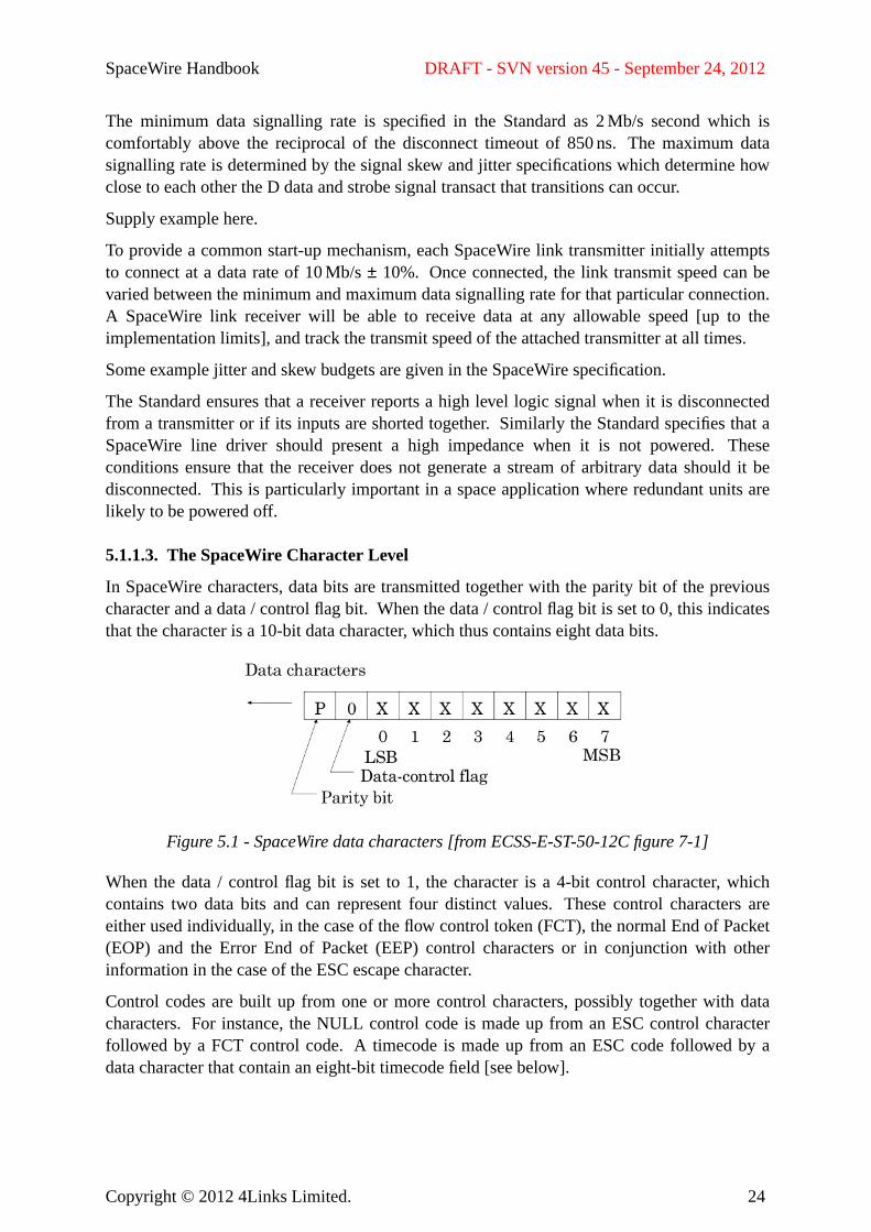
In SpaceWire characters, data bits are transmitted together with the parity bit of the previouscharacter and a data / control flag bit.When the data / control flag bit is set to 0, this indicatesthat the character is a 10-bit data character, which thus contains eight data bits.
Figure 5.1 - SpaceWire data characters [from ECSS-E-ST-50-12C figure 7-1]
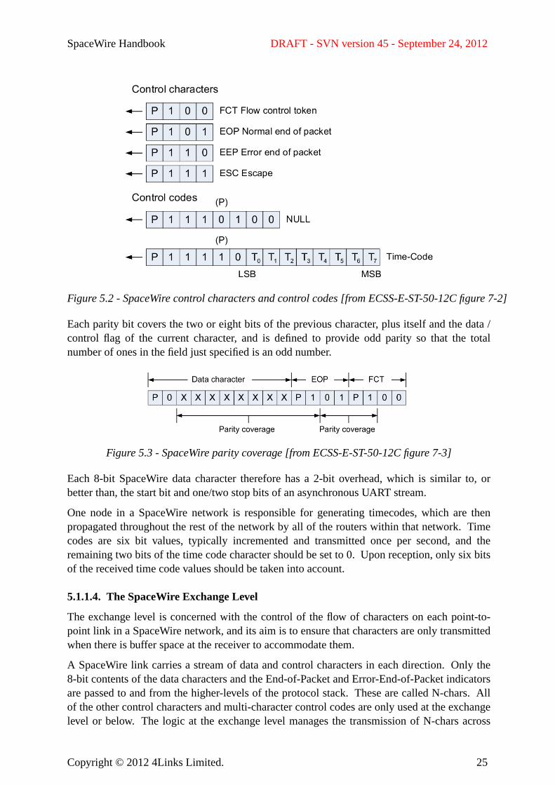
When the data / control flag bit is set to 1, the character is a 4-bit control character, whichcontains two data bits and can represent four distinct values. Thesecontrol characters areeither used individually, in the case of the flow control token (FCT), the normal End of Packet(EOP) and the Error End of Packet (EEP) control characters or in conjunction with otherinformation in the case of the ESC escape character.
Control codes are built up from one or more control characters, possibly together with datacharacters. For instance, the NULL control code is made up from an ESC control characterfollowed by a FCT control code.A timecode is made up from an ESC code followed by adata character that contain an eight-bit timecode field [see below].
Copyright © 2012 4Links Limited. 24
SpaceWire Handbook DRAFT - SVN version 45 - September 24, 2012
Figure 5.2 - SpaceWire control characters and control codes [from ECSS-E-ST-50-12C figure 7-2]
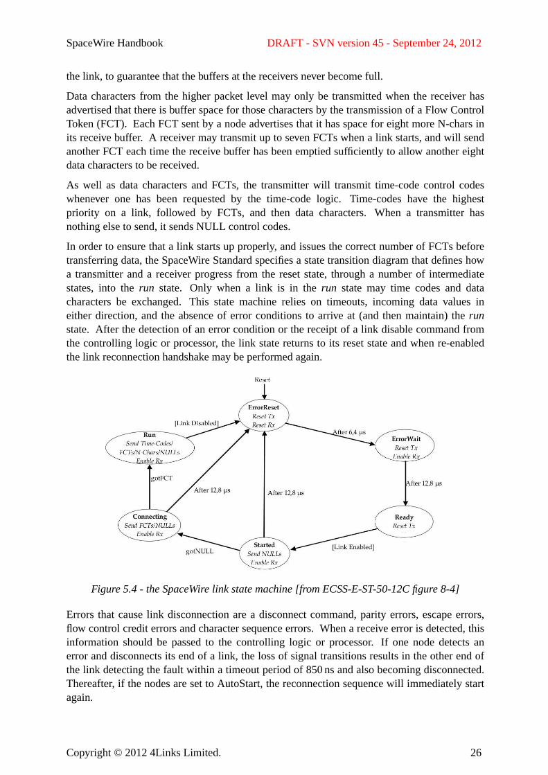
Each parity bit covers the two or eight bits of the previous character, plus itself and the data /control flag of the current character, and is defined to provide odd parity so that the totalnumber of ones in the field just specified is an odd number.
Figure 5.3 - SpaceWire parity coverage [from ECSS-E-ST-50-12C figure 7-3]
Each 8-bit SpaceWire data character therefore has a 2-bit overhead, which is similar to, orbetter than, the start bit and one/two stop bits of an asynchronous UART stream.
One node in a SpaceWire network is responsible for generating timecodes, which are thenpropagated throughout the rest of the network by all of the routers within that network. Timecodes are six bit values, typically incremented and transmitted once per second, and theremaining two bits of the time code character should be set to 0. Upon reception, only six bitsof the received time code values should be taken into account.
5.1.1.4. The SpaceWire Exchange Level
The exchange level is concerned with the control of the flow of characters on each point-to-point link in a SpaceWire network, and its aim is to ensure that characters are only transmittedwhen there is buffer space at the receiver to accommodate them.
A SpaceWire link carries a stream of data and control characters in each direction.Only the8-bit contents of the data characters and the End-of-Packet and Error-End-of-Packet indicatorsare passed to and from the higher-levels of the protocol stack. These are called N-chars.Allof the other control characters and multi-character control codes are only used at the exchangelevel or below. The logic at the exchange level manages the transmission of N-chars across
Copyright © 2012 4Links Limited. 25
SpaceWire Handbook DRAFT - SVN version 45 - September 24, 2012
the link, to guarantee that the buffers at the receivers never become full.
Data characters from the higher packet level may only be transmitted when the receiver hasadvertised that there is buffer space for those characters by the transmission of a Flow ControlToken (FCT). EachFCT sent by a node advertises that it has space for eight more N-chars inits receive buffer. A receiver may transmit up to seven FCTs when a link starts, and will sendanother FCT each time the receive buffer has been emptied sufficiently to allow another eightdata characters to be received.
As well as data characters and FCTs, the transmitter will transmit time-code control codeswhenever one has been requested by the time-code logic.Time-codes have the highestpriority on a link, followed by FCTs, and then data characters. When a transmitter hasnothing else to send, it sends NULL control codes.
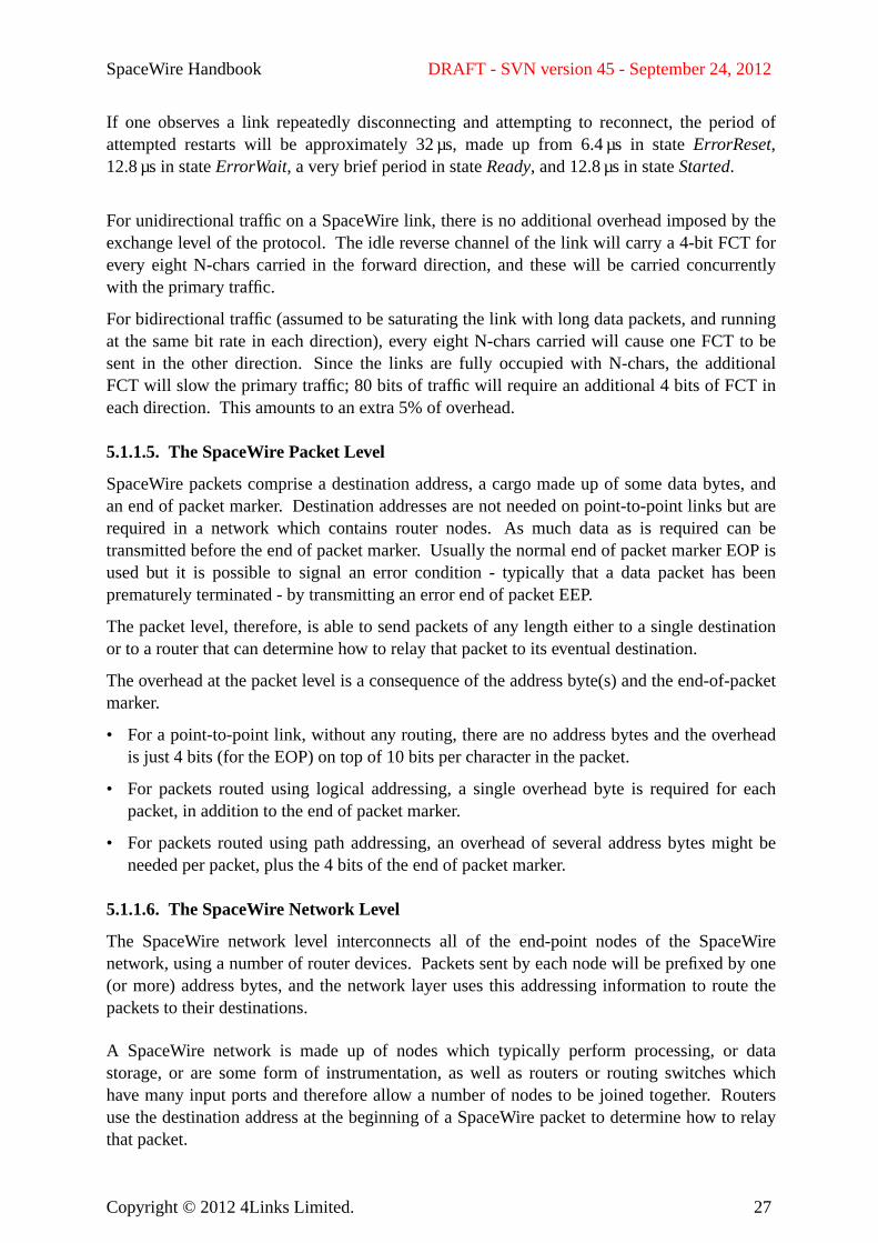
In order to ensure that a link starts up properly, and issues the correct number of FCTs beforetransferring data, the SpaceWire Standard specifies a state transition diagram that defines howa transmitter and a receiver progress from the reset state, through a number of intermediatestates, into therun state. Onlywhen a link is in therun state may time codes and datacharacters be exchanged. Thisstate machine relies on timeouts, incoming data values ineither direction, and the absence of error conditions to arrive at (and then maintain) therunstate. Afterthe detection of an error condition or the receipt of a link disable command fromthe controlling logic or processor, the link state returns to its reset state and when re-enabledthe link reconnection handshake may be performed again.
Figure 5.4 - the SpaceWire link state machine [from ECSS-E-ST-50-12C figure 8-4]
Errors that cause link disconnection are a disconnect command, parity errors, escape errors,flow control credit errors and character sequence errors.When a receive error is detected, thisinformation should be passed to the controlling logic or processor. If one node detects anerror and disconnects its end of a link, the loss of signal transitions results in the other end ofthe link detecting the fault within a timeout period of 850ns and also becoming disconnected.Thereafter, if the nodes are set to AutoStart, the reconnection sequence will immediately startagain.
Copyright © 2012 4Links Limited. 26
SpaceWire Handbook DRAFT - SVN version 45 - September 24, 2012
If one observes a link repeatedly disconnecting and attempting to reconnect, the period ofattempted restarts will be approximately 32µs, made up from 6.4 µs in stateErrorReset,12.8 µsin stateErrorWait, a very brief period in stateReady, and 12.8 µs in stateStarted.
For unidirectional traffic on a SpaceWire link, there is no additional overhead imposed by theexchange level of the protocol. The idle reverse channel of the link will carry a 4-bit FCT forev ery eight N-chars carried in the forward direction, and these will be carried concurrentlywith the primary traffic.
For bidirectional traffic (assumed to be saturating the link with long data packets, and runningat the same bit rate in each direction), every eight N-chars carried will cause one FCT to besent in the other direction.Since the links are fully occupied with N-chars, the additionalFCT will slow the primary traffic; 80 bits of traffic will require an additional 4 bits of FCT ineach direction. This amounts to an extra 5% of overhead.
5.1.1.5. The SpaceWire Packet Level
SpaceWire packets comprise a destination address, a cargo made up of some data bytes, andan end of packet marker. Destination addresses are not needed on point-to-point links but arerequired in a network which contains router nodes.As much data as is required can betransmitted before the end of packet marker. Usually the normal end of packet marker EOP isused but it is possible to signal an error condition - typically that a data packet has beenprematurely terminated - by transmitting an error end of packet EEP.
The packet level, therefore, is able to send packets of any length either to a single destinationor to a router that can determine how to relay that packet to its eventual destination.
The overhead at the packet level is a consequence of the address byte(s) and the end-of-packetmarker.
• For a point-to-point link, without any routing, there are no address bytes and the overheadis just 4 bits (for the EOP) on top of 10 bits per character in the packet.
• For packets routed using logical addressing, a single overhead byte is required for eachpacket, in addition to the end of packet marker.
• For packets routed using path addressing, an overhead of several address bytes might beneeded per packet, plus the 4 bits of the end of packet marker.
5.1.1.6. The SpaceWire Network Level
The SpaceWire network level interconnects all of the end-point nodes of the SpaceWirenetwork, using a number of router devices. Packets sent by each node will be prefixed by one(or more) address bytes, and the network layer uses this addressing information to route thepackets to their destinations.
A SpaceWire network is made up of nodes which typically perform processing, or datastorage, or are some form of instrumentation, as well as routers or routing switches whichhave many input ports and therefore allow a number of nodes to be joined together. Routersuse the destination address at the beginning of a SpaceWire packet to determine how to relaythat packet.
Copyright © 2012 4Links Limited. 27
SpaceWire Handbook DRAFT - SVN version 45 - September 24, 2012
A router only accepts data for any particular link connection when there is buffer spaceavailable at the receiving node. It uses the flow control credit advertised by the receiver of amessage to ensure that its output links are never flooded with data that cannot be successfullyreceived. This flow control blocking propagates right across a SpaceWire network andtherefore ensures that no data can be lost in transmission.Within each router, data bytespropagate from input port to output port just as soon as they are received; this is wormholerouting rather than store-and-forward routing. Wormhole routing considerably reduces thelatency of transmissions, especially when multiple routers are cascaded together in a largenetwork.
The first form of addressing within a SpaceWire network is the path addressing schemewhich uses header deletion. An address byte of zero results in the packet being routed to thecontrol logic within this particular switch; an address of 1 up to 32 is treated as a path address;and the other values are used as logical addresses.
In path addressing, each router receives the header address bytes at the start of a packet anduses the first one to determine the output port to which that message should be transmitted.Upon transmission, that header byte is deleted. Therefore a message with a number of headeraddress bytes will have them successively removed as the message propagates through anetwork of routers, and when it arrives at its destination there will be no header address bytesremaining. Allrouters must implement path addressing.
A second form of addressing within a SpaceWire network is logical addressing. If a routeuses logical addressing, it employs a routing table to translate the logical address number ineach packet to the physical output port that it will use to relay that packet. Eachrouter,therefore, needs to store a routing table that specifies how to relay a message from each of itsinput ports to any possible final destination within the network. It also stores a flag to indicatewhether the leading address byte should be removed when the packet is delivered to eachoutput port.
Group adaptive routing allows a routing switch with two or more SpaceWire links to anotherrouting switch to route incoming packets across any of those links, depending upon whichones are available at any instant. Thisprovides load balancing and ensures that the combinedlink bandwidth is used with maximum efficiency.
Alternatively, path addressing and logical addressing may be used together in a scheme calledregional logical addressing.In this case, it is possible to operate a group of routers usinglogical addressing within a wider environment that uses path addressing.Each addressingbyte is used to route the packet through groups of one or more routers before it is deleted,exposing the next byte for further steps.
5.1.2. SpaceWire Performance
• Maximum throughput - unidirectional and bidirectional
• Link / network latency and effect on throughput
• Time code accuracy (limited due to NULL/Data skew)
Copyright © 2012 4Links Limited. 28
SpaceWire Handbook DRAFT - SVN version 45 - September 24, 2012
5.2. ECSS-E-ST-50-51C : SpaceWire Protocol IdentificationECSS-E-ST-50-51C specifies a SpaceWire packet format that provides:
• a one-byte logical address, as the packet arrives at the receiving node. Note that thislogical address might have been prefixed by other logical or path address bytes that mighthave been deleted as they passed through the routers in the SpaceWire network;
• a one-byte protocol identification value.
• further packet bytes corresponding to the packet format identified by the protocolidentification value byte.
As an alternative to the one-byte protocol identification value, a three-byte extended protocolidentifier may be used; the first byte of this is zero and the two that follow provide a 16-bitprotocol identification value in big-endian byte order.
Four protocol identifier values have currently been standardised. The Remote MemoryAccess Protocol and the CCSDS Packet Transfer Protocol are specified in ECSS-E-ST-50-52and ECSS-E-ST-50-53 respectively and these are discussed in the next two sections of thisHandbook. TheGOES-R Reliable Data Delivery Protocol [NASA 2005] and Serial TransferUniversal Protocol [EADS 2009] are not specified by the ECSS.
There is a reserved range of project-specific protocol identifier values that may be used withinindividual programmes.
5.3. ECSS-E-ST-50-52C : the Remote Memory Access ProtocolThe SpaceWire Remote Memory Access Protocol (RMAP) defined in ECSS-E-ST-50-52C isa client-server protocol that provides a mechanism to read and write memory at a node in aSpaceWire network. It has gained popularity because it models the way that people are usedto using a physical bus and thus helps them to map a model of that bus onto their SpaceWirenetwork.
The RMAP protocol achieves these goals in a general fashion, which provides flexibility , butwith high overheads for small transfers. All of the SpaceWire addressing schemes areaccommodated - path addressing, logical addressing and regional addressing.
5.3.1. Commentary on the SpaceWire RMAP Standard
The Remote Memory Access Protocol (RMAP) provides a general register-setting andmemory access service.Particular applications include:
• Controlling SpaceWire nodes by setting and reading their memory-mapped registers;
• Configuring routing switches, where a special configuration port is provided for thepurpose;
• Transferring data to and from nodes, either in addressed blocks from memory or as acontinuous stream at a non-incrementing port address.
Copyright © 2012 4Links Limited. 29
SpaceWire Handbook DRAFT - SVN version 45 - September 24, 2012
The protocol provides commands for read, write, and read-modify-write.The commandheader is quite large (16 bytes plus a return path address, if needed for the SpaceWireaddressing scheme in use).As a consequence, reading or writing a single 32-bit wordrequires more than four extra words of overhead. Thisoverhead decreases as the data sizeincreases.
A CRC is provided to protect the RMAP protocol header, since it is important not to accessthe wrong memory address, to issue the wrong command, or to return the acknowledgementpacket to the wrong SpaceWire node address.The CRC is only eight bits in length, which isnot particularly secure, but this is in addition to the parity bits within each SpaceWirecharacter, and so overall this mechanism is fairly robust. ACRC is also provided for the datathat is written by an RMAP command, and for that which is read. This CRC is also only eightbits in length. The CRC algorithm used for both checks returns a value of zero if all of thebytes checked are themselves zero, so be aware that the CRC check of a buffer containing allzeroes will be successful.
Monitoring RMAP commands and responses for correct checksums is a good test of thewhole SpaceWire network, especially if incrementing Transaction IDs can be used to identifyany packet loss.
The ECSS-E-ST-50-52C RMAP protocol specification contains many configurable andoptional features. Care must be taken to check the implementation details to determinewhether two nodes will interoperate successfully. The basic RMAP read/write operationsmay be assumed to exist.
The RMAP Standard does not provide much guidance on:
• How the protocol (and higher-level applications in the affected nodes) operate in thepresence of link errors;
• How to handle concurrency issues safely - such as synchronising exchanged data andmanaging semaphores.
5.4. ECSS-E-ST-50-53C : the CCSDS Packet Transfer ProtocolThe ECSS-E-ST-50-53C CCSDS Packet Transfer Protocol transfers CCSDS Space Packetsacross a SpaceWire network. It encapsulates each CCSDS packet in a SpaceWire packet,routes it to its destination, and then removes the encapsulation to reveal the original CCSDSpacket. In addition to the CCSDS packet itself, the protocol carries an ECSS-E-ST-50-51CProtocol Identifier field, a packet length value, a Target SpaceWire Address (of arbitrarylength) and a one-byte Target Logical Address, a single-byte User Application Value, and areserved 8-bit field that is always set to 0x00.The length of the CCSDS Space Packet isdetermined by the length of the encapsulating SpaceWire packet, i.e. by the receipt of theSpaceWire EOP character.
The CCSDS Packet Transfer Protocol provides unidirectional data transfers across point-to-point links with no guarantees for successful delivery. The protocol is asynchronous and anyresponse message would have to be conveyed by a separate mechanism, such as a secondCCSDS Packet Transfer Protocol channel.
Copyright © 2012 4Links Limited. 30
SpaceWire Handbook DRAFT - SVN version 45 - September 24, 2012
6. Specific Implementation TopicsThis section provides guidance on topics that are important for a successful SpaceWireimplementation.
6.1. Physical Layer InterconnectionsThis section deals with the physical layer electrical interconnection issues such as LVDSsignals, grounding and PCB layouts.
6.1.1. SpaceWire Binary Encoding
SpaceWire communication is pure digital, using Low Voltage Differential Signaling (LVDS).These two-level binary signals are recovered by a simple line-receiver with no signalprocessing requirement. The line code is a Gray-code which allows bit-boundaries to berecovered from the data stream - the transmit clock is recovered at the receiver. As a result avery wide range of speeds is automatically supported by SpaceWire (currently from <2Mb/sto over 600 Mb/s). Bit-to-bit speed change capability is a useful by- product that allowsspread-spectrum clocking to reduce electromagnetic interference and also allows reducedpower consumption by throttling back the transmit speed when there is no active data totransmit.
6.1.2. LV DS Signals and Levels
The SpaceWire physical layer is required to use Low Voltage Differential Signalling (LVDS)as defined in the document ANSI/TIA/EIA-644 (A). There are other LVDS specifications,including M-LVDS, B-LVDS and the IEEE 1596 signal specification that are sometimes alsodiscussed in the context of SpaceWire.
LVDS specifies a low differential output voltage, nominally 350mV, sitting at a definedcommon mode level, nominally 1.25V. The nominal output terminal voltages are thusbetween 1.075V and 1.425V. This allows an end-to-end voltage difference between groundwires (the common mode voltage range) of±1 V whilst keeping the receiver input terminalvoltages between 0.075V and 2.425V.
It is often believed (and implied in the ECSS-E-ST-50-12C SpaceWire Standard [section4.3.2]) that LVDS drivers must be current sources. In fact, the circuit shown completely failsto achieve the common-mode voltage requirement and must be understood as a simplifiedillustration, not an actual implementation. True current sources cannot control the outputcommon mode level and are always used within a feedback loop which has the effect ofmaking them behave more as voltage sources, as the LVDS standard requires (the Standardspecifies output voltages, not currents).
Devices such as the Actel RTAX use voltage outputs and a resistor network to produce correctLVDS levels. A lower supply voltage (2.5 V) is used than dedicated LVDS drivers (3.3V or5 V) and the off-chip series resistors limit fault currents.[Silicon commonly fails lowimpedance (short-circuit or avalanche conduction) which can deliver large fault currents.]Actel specifies these LVDS circuits for operation up to 350 Mb/s (Xilinx achieves >1 Gb/s).The suggested resistor network has the further benefit of providing a matched impedance at
Copyright © 2012 4Links Limited. 31
SpaceWire Handbook DRAFT - SVN version 45 - September 24, 2012
the source which absorbs any signal reflections or noise; perfect current mode (or perfectvoltage mode) sources would totally reflect such interference to degrade data.
The reasons why the LVDS outputs must be controlled include:
• the control of signal rise-times to reduce the EMC spectrum;
• the control of link outputs when switching nominal and redundant modules;
• the control of over-voltage outputs under fault conditions;
It is difficult to find slow LVDS buffers. A typical rise/fall time of 1 ns is quite slow for suchdevices; 300 ps is more typical. The LVDS standard allow the rise/fall times to be as long as30% of the bit period.For SpaceWire data rates of up to 50 Mb/s, the bit-period is 20 ns ormore and typical LVDS buffers are an order of magnitude faster than is necessary. Such over-specification produces a greatly extended emission spectrum and requires much tightermatching of wire lengths and produces greater reflections from impedance mismatches suchas occur in the micro-D connectors.If the rise and fall times were matched to the data rate,we would limit the highest frequencies produced and greatly ease construction.
More information about LVDS signalling for SpaceWire can be found in [Cook 2008a] andthe effect of edge times on emissions in [Cook 2007c].
6.1.3. SpaceWire codec implementation
To be supplied. Shouldalso add references to works on metastability. [Ginosar 2003,Ginosar 2011]
To be supplied - information on clock recovery circuits.
6.1.3.1. Asynchronous issues at the logic level
In most cases, the processors or I/O hardware at either end of a SpaceWire link will haveindependent hardware clocks. The challenge for the hardware designer is how to transitionfrom the transmit clock domain into the receive clock domain at each end of each link.Theprimary issue facing the CODEC designer, therefore, is that of metastability avoidance[Ginosar 2003, Ginosar 2011].
More information about asynchronous issues for SpaceWire can be found in [Cook 2008b].
6.1.4. SpaceWire Cabling
SpaceWire takes considerable trouble to specify cable and its use to reduce electromagneticemissions. Cables,by virtue of their length, can form effective electromagnetic radiators.Shielded cable is specified for SpaceWire to reduce radiation from the signal conductorswhich are, in turn, differential pairs to balance flow and return currents and limit emissions.
Unfortunately, the specified SpaceWire connector is not designed for balanced signals andintroduces noticeable imbalance between wires of a pair. This reduces the effectiveness ofbalanced transmission, getting progressively worse at higher frequencies, resulting inincreased emissions.
Copyright © 2012 4Links Limited. 32
SpaceWire Handbook DRAFT - SVN version 45 - September 24, 2012
There is material on the shielding out there, including figures for what makes a goodconnection (in the EMC literature).
6.1.5. Grounding
To be supplied.
6.1.6. Printed Circuit Board layout
The design of printed circuit boards for SpaceWire units should follow best practice for thepropagation of high-speed differential signals. These include:
• Ensure that the impedance of each SpaceWire differential track pair is 100Ω bycalculating the appropriate track widths and spacing between tracks using the relevantmicrostrip/stripline equations.
• Minimise skew within each differential track pair and between Din/Sin and Dout/Soutpairs by ensuring that their lengths are the same.
• Minimise discontinuities on the signal paths, i.e. reduce the number of vias, and use arcsor 45 degree bevels rather than 90-degree bends in the PCB tracks.
• Isolate the link signals, as far as possible, from any single ended neighboring signals.This should preferably be done by routing them on separate PCB layers.
• Stub lengths on the link tracks should be kept as short as possible.
• The LVDS drivers and receivers should be kept as close as possible to the relevantconnector, to minimise opportunities for noise pick-up.
6.1.7. Other EMC Issues
To be supplied.
6.1.7.1. EMC Mitigation through Token Randomisation
The only frequent individual control token used in SpaceWire is the Flow Control Token(FCT). Data may fully occupy the stream resulting in a periodicity of 10-bits. When no dataor flow control is sent the link sends NULL characters (so that a disconnection can bedetected), each of which consists of a pair of control tokens, giving periodicities of 4- and8-bits. NULLs, because they are regular and unchanging, concentrate energy into a smallnumber of narrow-band signals.
Some communication schemes randomise data, including idle sequences, in order to spreadnarrow concentrations of energy over a wider frequency range. Although data randomisationis possible with SpaceWire, it adds considerable complexity to an otherwise simple design -and cannot include NULL tokens, thus seriously limiting the benefit.
Copyright © 2012 4Links Limited. 33
SpaceWire Handbook DRAFT - SVN version 45 - September 24, 2012
6.1.7.2. EMC Mitigation through Bit Rate Randomisation
Although the SpaceWire Standard refers to jitter in the D and S signals, this is not actually alimiting factor. It is necessary to recover the transmit clock and to use this to latch (on bothedges) D to recover the data stream. The real limiting factor is determined by the quality ofthe recovered clock and this is determined by the edge-to-edge spacing in the DS signals (D toD, D to S, etc.). The actual frequency of the clock is unimportant so long as it exceeds aminimum value, determined by the timeout detector (˜2Mb/s), and is below a maximum valuedetermined by the receiver implementation.
It is perfectly allowable for the data rate to change from one extreme to the other (or anylesser range) from one bit to the next (incidentally, providing a potentially useful powersaving facility). In fact, it is required to do so since a link must start at 10Mb/s and thenchange, mid-bit-stream, to the working rate.
Thus it is possible to alter the edge-to-edge spacing (bit period) in a random sequence - atechnique used elsewhere and known as spread-spectrum-clocking.This spreads the energy insingle-frequency spikes over a range of nearby frequencies and reduces the peak levelssignificantly. It can easily be applied to SpaceWire, without rendering the implementationnon-conformant to the Standard.
6.2. Reducing Jitter in Time Codes / other placesMore information about time-code jitter reduction for SpaceWire can be found in [Cook2003].
6.3. SpaceWire Routing IssuesThe SpaceWire Standard requires that routing switches should provide path addressing, andpermits them also to provide logical addressing and its variant, regional addressing.Seesection 4.2.4, “Packet Routing”, for details of these schemes.
Specific issues regarding routing are those of router latency, and the potential for corruption ofthe logical addressing routing tables.
6.3.1. Wormhole Routing
SpaceWire routers are required to use wormhole routing, in which the head of a packet ‘pulls’the rest of the packet through the router.
Copyright © 2012 4Links Limited. 34
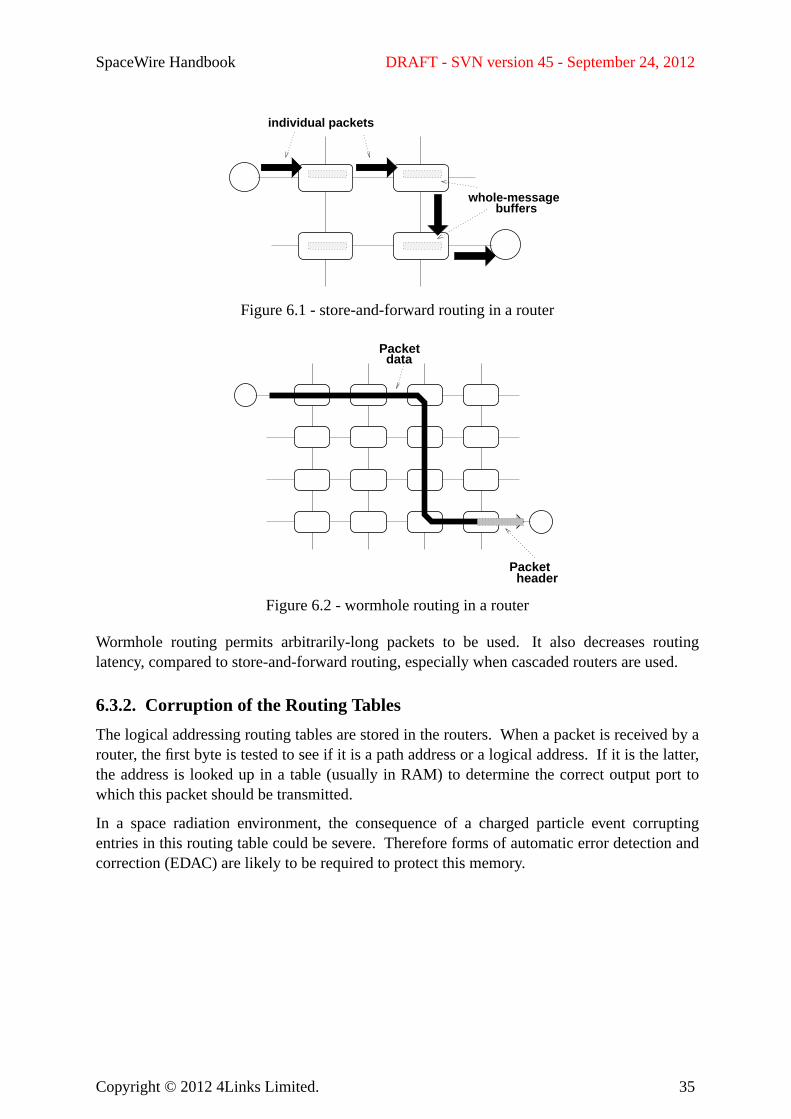
SpaceWire Handbook DRAFT - SVN version 45 - September 24, 2012
whole-messagebuffers
individual packets
Figure 6.1 - store-and-forward routing in a router
headerPacket
Packetdata
Figure 6.2 - wormhole routing in a router
Wormhole routing permits arbitrarily-long packets to be used. It also decreases routinglatency, compared to store-and-forward routing, especially when cascaded routers are used.
6.3.2. Corruption of the Routing Tables
The logical addressing routing tables are stored in the routers. When a packet is received by arouter, the first byte is tested to see if it is a path address or a logical address.If it is the latter,the address is looked up in a table (usually in RAM) to determine the correct output port towhich this packet should be transmitted.
In a space radiation environment, the consequence of a charged particle event corruptingentries in this routing table could be severe. Thereforeforms of automatic error detection andcorrection (EDAC) are likely to be required to protect this memory.
Copyright © 2012 4Links Limited. 35
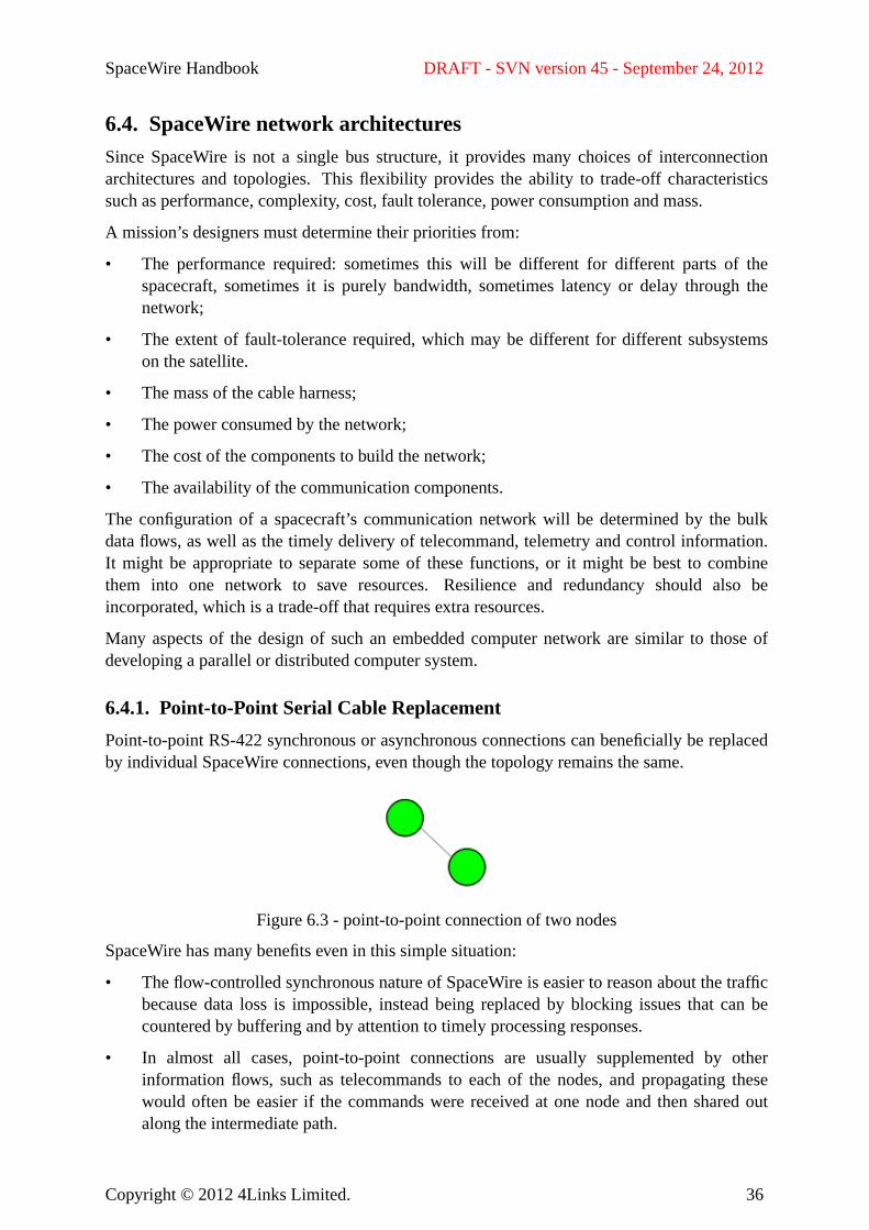
SpaceWire Handbook DRAFT - SVN version 45 - September 24, 2012
6.4. SpaceWire network architecturesSince SpaceWire is not a single bus structure, it provides many choices of interconnectionarchitectures and topologies. This flexibility provides the ability to trade-off characteristicssuch as performance, complexity, cost, fault tolerance, power consumption and mass.
A mission’s designers must determine their priorities from:
• The performance required: sometimes this will be different for different parts of thespacecraft, sometimes it is purely bandwidth, sometimes latency or delay through thenetwork;
• The extent of fault-tolerance required, which may be different for different subsystemson the satellite.
• The mass of the cable harness;
• The power consumed by the network;
• The cost of the components to build the network;
• The availability of the communication components.
The configuration of a spacecraft’s communication network will be determined by the bulkdata flows, as well as the timely delivery of telecommand, telemetry and control information.It might be appropriate to separate some of these functions, or it might be best to combinethem into one network to save resources. Resilienceand redundancy should also beincorporated, which is a trade-off that requires extra resources.
Many aspects of the design of such an embedded computer network are similar to those ofdeveloping a parallel or distributed computer system.
6.4.1. Point-to-Point Serial Cable Replacement
Point-to-point RS-422 synchronous or asynchronous connections can beneficially be replacedby individual SpaceWire connections, even though the topology remains the same.
Figure 6.3 - point-to-point connection of two nodes
SpaceWire has many benefits even in this simple situation:
• The flow-controlled synchronous nature of SpaceWire is easier to reason about the trafficbecause data loss is impossible, instead being replaced by blocking issues that can becountered by buffering and by attention to timely processing responses.
• In almost all cases, point-to-point connections are usually supplemented by otherinformation flows, such as telecommands to each of the nodes, and propagating thesewould often be easier if the commands were received at one node and then shared outalong the intermediate path.
Copyright © 2012 4Links Limited. 36
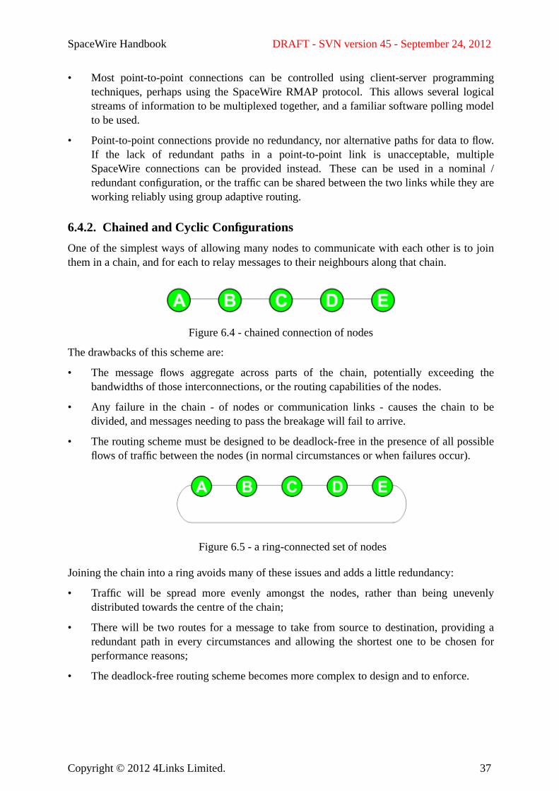
SpaceWire Handbook DRAFT - SVN version 45 - September 24, 2012
• Most point-to-point connections can be controlled using client-server programmingtechniques, perhaps using the SpaceWire RMAP protocol. This allows several logicalstreams of information to be multiplexed together, and a familiar software polling modelto be used.
• Point-to-point connections provide no redundancy, nor alternative paths for data to flow.If the lack of redundant paths in a point-to-point link is unacceptable, multipleSpaceWire connections can be provided instead. These can be used in a nominal /redundant configuration, or the traffic can be shared between the two links while they areworking reliably using group adaptive routing.
6.4.2. Chained and Cyclic Configurations
One of the simplest ways of allowing many nodes to communicate with each other is to jointhem in a chain, and for each to relay messages to their neighbours along that chain.
Figure 6.4 - chained connection of nodes
The drawbacks of this scheme are:
• The message flows aggregate across parts of the chain, potentially exceeding thebandwidths of those interconnections, or the routing capabilities of the nodes.
• Any failure in the chain - of nodes or communication links - causes the chain to bedivided, and messages needing to pass the breakage will fail to arrive.
• The routing scheme must be designed to be deadlock-free in the presence of all possibleflows of traffic between the nodes (in normal circumstances or when failures occur).
Figure 6.5 - a ring-connected set of nodes
Joining the chain into a ring avoids many of these issues and adds a little redundancy:
• Traffic will be spread more evenly amongst the nodes, rather than being unevenlydistributed towards the centre of the chain;
• There will be two routes for a message to take from source to destination, providing aredundant path in every circumstances and allowing the shortest one to be chosen forperformance reasons;
• The deadlock-free routing scheme becomes more complex to design and to enforce.
Copyright © 2012 4Links Limited. 37
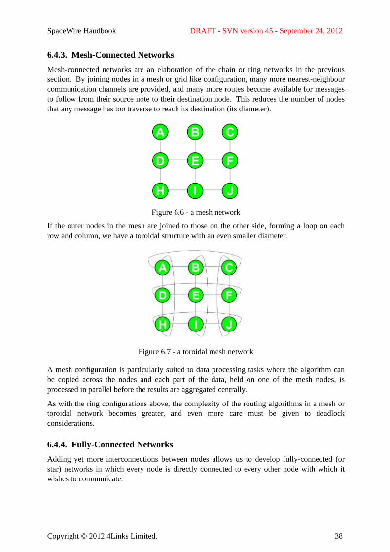
SpaceWire Handbook DRAFT - SVN version 45 - September 24, 2012
6.4.3. Mesh-Connected Networks
Mesh-connected networks are an elaboration of the chain or ring networks in the previoussection. Byjoining nodes in a mesh or grid like configuration, many more nearest-neighbourcommunication channels are provided, and many more routes become available for messagesto follow from their source note to their destination node.This reduces the number of nodesthat any message has too traverse to reach its destination (its diameter).
Figure 6.6 - a mesh network
If the outer nodes in the mesh are joined to those on the other side, forming a loop on eachrow and column, we have a toroidal structure with an even smaller diameter.
Figure 6.7 - a toroidal mesh network
A mesh configuration is particularly suited to data processing tasks where the algorithm canbe copied across the nodes and each part of the data, held on one of the mesh nodes, isprocessed in parallel before the results are aggregated centrally.
As with the ring configurations above, the complexity of the routing algorithms in a mesh ortoroidal network becomes greater, and even more care must be given to deadlockconsiderations.
6.4.4. Fully-Connected Networks
Adding yet more interconnections between nodes allows us to develop fully-connected (orstar) networks in which every node is directly connected to every other node with which itwishes to communicate.
Copyright © 2012 4Links Limited. 38
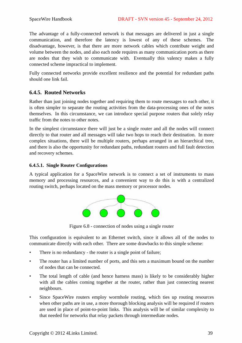
SpaceWire Handbook DRAFT - SVN version 45 - September 24, 2012
The advantage of a fully-connected network is that messages are delivered in just a singlecommunication, and therefore the latency is lowest of any of these schemes.Thedisadvantage, however, is that there are more network cables which contribute weight andvolume between the nodes, and also each node requires as many communication ports as thereare nodes that they wish to communicate with.Eventually this valency makes a fullyconnected scheme impractical to implement.
Fully connected networks provide excellent resilience and the potential for redundant pathsshould one link fail.
6.4.5. Routed Networks
Rather than just joining nodes together and requiring them to route messages to each other, itis often simpler to separate the routing activities from the data-processing ones of the notesthemselves. Inthis circumstance, we can introduce special purpose routers that solely relaytraffic from the notes to other notes.
In the simplest circumstance there will just be a single router and all the nodes will connectdirectly to that router and all messages will take two hops to reach their destination. In morecomplex situations, there will be multiple routers, perhaps arranged in an hierarchical tree,and there is also the opportunity for redundant paths, redundant routers and full fault detectionand recovery schemes.
6.4.5.1. Single Router Configurations
A typical application for a SpaceWire network is to connect a set of instruments to massmemory and processing resources, and a convenient way to do this is with a centralizedrouting switch, perhaps located on the mass memory or processor nodes.
Figure 6.8 - connection of nodes using a single router
This configuration is equivalent to an Ethernet switch, since it allows all of the nodes tocommunicate directly with each other. There are some drawbacks to this simple scheme:
• There is no redundancy - the router is a single point of failure;
• The router has a limited number of ports, and this sets a maximum bound on the numberof nodes that can be connected.
• The total length of cable (and hence harness mass) is likely to be considerably higherwith all the cables coming together at the router, rather than just connecting nearestneighbours.
• Since SpaceWire routers employ wormhole routing, which ties up routing resourceswhen other paths are in use, a more thorough blocking analysis will be required if routersare used in place of point-to-point links. This analysis will be of similar complexity tothat needed for networks that relay packets through intermediate nodes.
Copyright © 2012 4Links Limited. 39
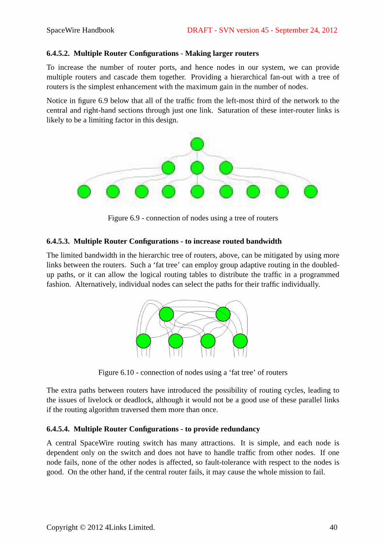
SpaceWire Handbook DRAFT - SVN version 45 - September 24, 2012
6.4.5.2. Multiple Router Configurations - Making larger routers
To increase the number of router ports, and hence nodes in our system, we can providemultiple routers and cascade them together. Providing a hierarchical fan-out with a tree ofrouters is the simplest enhancement with the maximum gain in the number of nodes.
Notice in figure 6.9 below that all of the traffic from the left-most third of the network to thecentral and right-hand sections through just one link. Saturation of these inter-router links islikely to be a limiting factor in this design.
Figure 6.9 - connection of nodes using a tree of routers
6.4.5.3. Multiple Router Configurations - to increase routed bandwidth
The limited bandwidth in the hierarchic tree of routers, above, can be mitigated by using morelinks between the routers. Such a ‘fat tree’ can employ group adaptive routing in the doubled-up paths, or it can allow the logical routing tables to distribute the traffic in a programmedfashion. Alternatively, individual nodes can select the paths for their traffic individually.
Figure 6.10 - connection of nodes using a ‘fat tree’ of routers
The extra paths between routers have introduced the possibility of routing cycles, leading tothe issues of livelock or deadlock, although it would not be a good use of these parallel linksif the routing algorithm traversed them more than once.
6.4.5.4. Multiple Router Configurations - to provide redundancy
A central SpaceWire routing switch has many attractions. It is simple, and each node isdependent only on the switch and does not have to handle traffic from other nodes. If onenode fails, none of the other nodes is affected, so fault-tolerance with respect to the nodes isgood. Onthe other hand, if the central router fails, it may cause the whole mission to fail.
Copyright © 2012 4Links Limited. 40
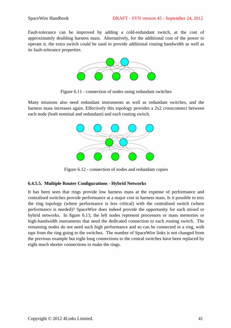
SpaceWire Handbook DRAFT - SVN version 45 - September 24, 2012
Fault-tolerance can be improved by adding a cold-redundant switch, at the cost ofapproximately doubling harness mass.Alternatively, for the additional cost of the power tooperate it, the extra switch could be used to provide additional routing bandwidth as well asits fault-tolerance properties.
Figure 6.11 - connection of nodes using redundant switches
Many missions also need redundant instruments as well as redundant switches, and theharness mass increases again. Effectively this topology provides a 2x2 crossconnect betweeneach node (both nominal and redundant) and each routing switch.
Figure 6.12 - connection of nodes and redundant copies
6.4.5.5. Multiple Router Configurations - Hybrid Networks
It has been seen that rings provide low harness mass at the expense of performance andcentralised switches provide performance at a major cost in harness mass. Is it possible to mixthe ring topology (where performance is less critical) with the centralised switch (whereperformance is needed)? SpaceWire does indeed provide the opportunity for such mixed orhybrid networks. In figure 6.13, the left nodes represent processors or mass memories orhigh-bandwidth instruments that need the dedicated connection to each routing switch.Theremaining nodes do not need such high performance and so can be connected in a ring, withtaps from the ring going to the switches.The number of SpaceWire links is not changed fromthe previous example but eight long connections to the central switches have been replaced byeight much shorter connections to make the rings.
Copyright © 2012 4Links Limited. 41
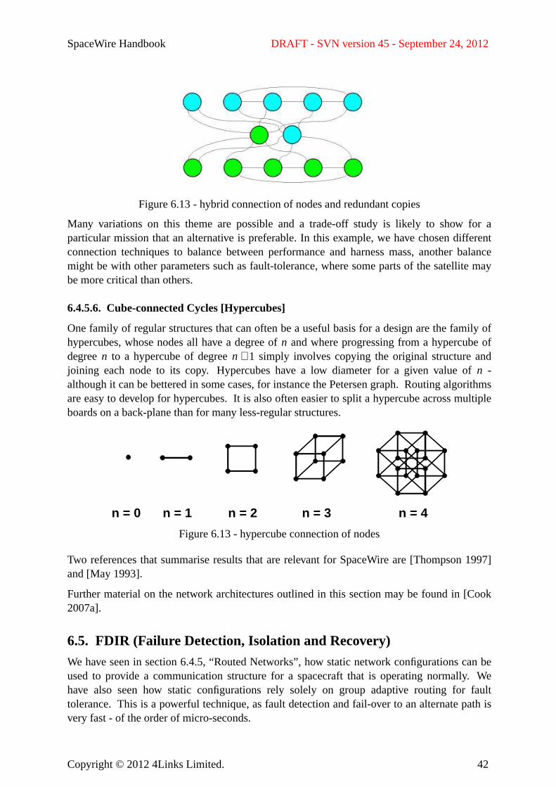
SpaceWire Handbook DRAFT - SVN version 45 - September 24, 2012
Figure 6.13 - hybrid connection of nodes and redundant copies
Many variations on this theme are possible and a trade-off study is likely to show for aparticular mission that an alternative is preferable. In this example, we have chosen differentconnection techniques to balance between performance and harness mass, another balancemight be with other parameters such as fault-tolerance, where some parts of the satellite maybe more critical than others.
6.4.5.6. Cube-connected Cycles [Hypercubes]
One family of regular structures that can often be a useful basis for a design are the family ofhypercubes, whose nodes all have a degree ofn and where progressing from a hypercube ofdegreen to a hypercube of degreen + 1 simply involves copying the original structure andjoining each node to its copy. Hypercubes have a low diameter for a given value of n -although it can be bettered in some cases, for instance the Petersen graph. Routing algorithmsare easy to develop for hypercubes. Itis also often easier to split a hypercube across multipleboards on a back-plane than for many less-regular structures.
n = 0 n = 1 n = 2 n = 3 n = 4
Figure 6.13 - hypercube connection of nodes
Tw o references that summarise results that are relevant for SpaceWire are [Thompson 1997]and [May 1993].
Further material on the network architectures outlined in this section may be found in [Cook2007a].
6.5. FDIR (Failure Detection, Isolation and Recovery)We hav eseen in section 6.4.5, “Routed Networks”, how static network configurations can beused to provide a communication structure for a spacecraft that is operating normally. Wehave also seen how static configurations rely solely on group adaptive routing for faulttolerance. Thisis a powerful technique, as fault detection and fail-over to an alternate path isvery fast - of the order of micro-seconds.
Copyright © 2012 4Links Limited. 42
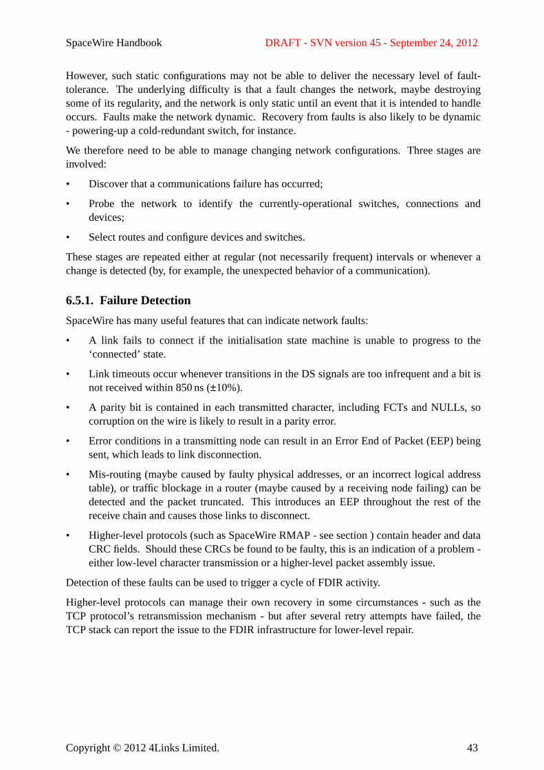
SpaceWire Handbook DRAFT - SVN version 45 - September 24, 2012
However, such static configurations may not be able to deliver the necessary level of fault-tolerance. Theunderlying difficulty is that a fault changes the network, maybe destroyingsome of its regularity, and the network is only static until an event that it is intended to handleoccurs. Faults make the network dynamic.Recovery from faults is also likely to be dynamic- powering-up a cold-redundant switch, for instance.
We therefore need to be able to manage changing network configurations. Three stages areinvolved:
• Discover that a communications failure has occurred;
• Probe the network to identify the currently-operational switches, connections anddevices;
• Select routes and configure devices and switches.
These stages are repeated either at regular (not necessarily frequent) intervals or whenever achange is detected (by, for example, the unexpected behavior of a communication).
6.5.1. Failur e Detection
SpaceWire has many useful features that can indicate network faults:
• A l ink fails to connect if the initialisation state machine is unable to progress to the‘connected’ state.
• Link timeouts occur whenever transitions in the DS signals are too infrequent and a bit isnot received within 850 ns (±10%).
• A parity bit is contained in each transmitted character, including FCTs and NULLs, socorruption on the wire is likely to result in a parity error.
• Error conditions in a transmitting node can result in an Error End of Packet (EEP) beingsent, which leads to link disconnection.
• Mis-routing (maybe caused by faulty physical addresses, or an incorrect logical addresstable), or traffic blockage in a router (maybe caused by a receiving node failing) can bedetected and the packet truncated.This introduces an EEP throughout the rest of thereceive chain and causes those links to disconnect.
• Higher-level protocols (such as SpaceWire RMAP - see section) contain header and dataCRC fields. Should these CRCs be found to be faulty, this is an indication of a problem -either low-level character transmission or a higher-level packet assembly issue.
Detection of these faults can be used to trigger a cycle of FDIR activity.
Higher-level protocols can manage their own recovery in some circumstances - such as theTCP protocol’s retransmission mechanism - but after several retry attempts have failed, theTCP stack can report the issue to the FDIR infrastructure for lower-level repair.
Copyright © 2012 4Links Limited. 43
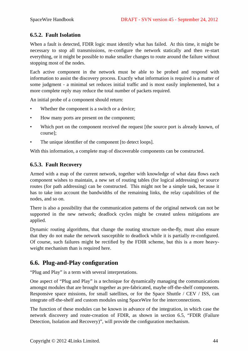
SpaceWire Handbook DRAFT - SVN version 45 - September 24, 2012
6.5.2. Fault Isolation
When a fault is detected, FDIR logic must identify what has failed. At this time, it might benecessary to stop all transmissions, re-configure the network statically and then re-startev erything, or it might be possible to make smaller changes to route around the failure withoutstopping most of the nodes.
Each active component in the network must be able to be probed and respond withinformation to assist the discovery process. Exactly what information is required is a matter ofsome judgment - a minimal set reduces initial traffic and is most easily implemented, but amore complete reply may reduce the total number of packets required.
An initial probe of a component should return:
• Whether the component is a switch or a device;
• How many ports are present on the component;
• Which port on the component received the request [the source port is already known, ofcourse];
• The unique identifier of the component [to detect loops].
With this information, a complete map of discoverable components can be constructed.
6.5.3. Fault Recovery
Armed with a map of the current network, together with knowledge of what data flows eachcomponent wishes to maintain, a new set of routing tables (for logical addressing) or sourceroutes (for path addressing) can be constructed.This might not be a simple task, because ithas to take into account the bandwidths of the remaining links, the relay capabilities of thenodes, and so on.
There is also a possibility that the communication patterns of the original network can not besupported in the new network; deadlock cycles might be created unless mitigations areapplied.
Dynamic routing algorithms, that change the routing structure on-the-fly, must also ensurethat they do not make the network susceptible to deadlock while it is partially re-configured.Of course, such failures might be rectified by the FDIR scheme, but this is a more heavy-weight mechanism than is required here.
6.6. Plug-and-Play configuration“Plug and Play” is a term with several interpretations.
One aspect of “Plug and Play” is a technique for dynamically managing the communicationsamongst modules that are brought together as pre-fabricated, maybe off-the-shelf components.Responsive space missions, for small satellites, or for the Space Shuttle / CEV / ISS, canintegrate off-the-shelf and custom modules using SpaceWire for the interconnections.
The function of these modules can be known in advance of the integration, in which case thenetwork discovery and route-creation of FDIR, as shown in section 6.5, “FDIR (FailureDetection, Isolation and Recovery)”, will provide the configuration mechanism.
Copyright © 2012 4Links Limited. 44
SpaceWire Handbook DRAFT - SVN version 45 - September 24, 2012
An enhanced form of “Plug and Play” provides an electronic datasheet function to themodules, so that their precise specification can be determined by the integration tools. In thiscase, the software interfaces, module communications, calibration and QA functions could allbe handled automatically.
6.7. BackplanesTo be supplied.
For further reading, see [Senior 2010a and Senior 2010b].
6.8. SpaceWire D vs Timed EthernetBoth the draft SpaceWire D and Timed Ethernet are effectively shared bus technologies.SpaceWire can implement each point-to-point link in a network as a bus, but this hides thesystem-wide benefits of timed comms.
6.9. SpaceWire Verification and ValidationBearing in mind the stringent quality requirements of the space industry, many users haverequested validation equipment to certify their SpaceWire designs, to certify that these designsmeet the detailed specifications of the SpaceWire Standard, and to state that their systems are“correct”.
There are several dangers in attempting to validate a SpaceWire design, to certify that thedesigns meets the detailed specifications of the SpaceWire Standard, or to state that a systemis “correct”.
The first is that it is impossible to test most systems that contain internal state just from theexterior (black box testing), because it is impossible to step those designs through all of theirinternal states in order to check them completely. In addition, even if it were possible toexplore every single state of such a system, the number of states might be so large as to makethis task impossible.Even a system with ann-bit integer variable contains 2n possible binarystates when each of its values is considered separately. Any realistic system is therefore goingto be impossible to test exhaustively.
The best that one can therefore achieve when testing a SpaceWire device or system istherefore :
• to explore all of the expected states of the system that can be reached through normaloperation by exercising it using a range of values that are allowed in the SpaceWirespecifications;
• to perform boundary testing by exploring ranges of situations that fall just outside ofthose allowed by the SpaceWire standards;
• to undertake stress testing by transmitting and receiving vast quantities of traffic andchecking for errors;
• to explore the timing relationships between events, such as the near-simultaneousstarting and ending of packets at each port of a SpaceWire router;
Copyright © 2012 4Links Limited. 45
SpaceWire Handbook DRAFT - SVN version 45 - September 24, 2012
• to fuzz-test the system by subjecting it to a range of seemingly random values that oughtnot to cause it to fail;
• to run experiments that exercise the system under test within the electrical envelope ofthe SpaceWire standards, as well as some that use electrical conditions just outside of theSpaceWire Standard that one could hopefully expect the system to handle gracefully;
• ... but bear in mind that it is impossible to build an exhaustive set of these circumstancesand that test coverage can therefore never reach 100%.
Testing therefore attempts to provide counterexamples of when a system does not successfullymeet the standards. Whilst it is possible to do this very successfully, it is impossible toguarantee to find all embedded failures.
Obviously, in white box testing, when one has access to the internal design and state of asystem, it is possible to perform much more exhaustive testing of those internal states thanblack-box testing can achieve.
Whilst it might be possible to build an excellent "Conformance Tester" unit, this could neverbe guaranteed to identify all the faults of a system-under-test and therefore should never claimthat it has validated that system to the SpaceWire Standard - or to any other standard, for thatmatter.
A thorough design review, including input from an engineer with a thorough understanding ofmetastability issues, should be considered essential.
6.9.1. Testing the Physical and Signal Layers
Assuming that the SpaceWire network being tested has been constructed using cabling andconnectors that meet the SpaceWire Standard, testing the physical layer mainly involvestesting for continuity in all the conductors and ensuring that the network is complete. It mightbe possible to use techniques such as time domain reflectometry to ensure that all of thecabling and printed circuit tracking meets impedance specifications.
Many tests are possible to qualify the signal layer. These include:
• injecting signals of known quantity quality and of known degradation into a SpaceWirenode and checking that all of the signal layer properties behave as expected.
• undertaking a margins analysis in conjunction with transmission of traffic at higherlevels of the SpaceWire protocol.
Sections 12.2.4 and 12.2.5 of the ECSS-E-ST-50-12C SpaceWire Standard provide asummary of all of the conformance items in the signal layer.
6.9.2. Testing the Higher SpaceWire Protocol Layers
There are many aspects of the network layer that can be exercised:
• Addressing from each input port of the route to each output port
• Writing logical addresses to all locations in the logical addressing table and thenpropagating data through a route under control of all of these routing table entries
Copyright © 2012 4Links Limited. 46
SpaceWire Handbook DRAFT - SVN version 45 - September 24, 2012
• Testing header deletion on the output of the router;
• Testing the optional header deletion in a router;
• Testing the buffering and blocking properties of the router when operating in thewormhole mode;
• Testing the behaviour when a router times out a packet because traffic has been blockedon one of its output ports [is this a 10X router function or a SpaceWire-specifiedfunction?]
• Testing how the router spills packets that block or are otherwise incorrect;
• Checking the router arbitration mechanisms that ensure that some operations areperformed in preference to others.
6.9.3. Testing Higher-level SpaceWire Protocols
Passing RMAP protocol traffic across the SpaceWire network under test is particularlyconvenient because all RMAP headers contain a CRC error check. All of the RMAP datafields (in RMAP memory read responses and in RMAP memory write commands) are alsoCRC-protected. Asa consequence, most low-level SpaceWire communication issues will bedetected as wrongly checksummed RMAP packets or as incomplete RMAP client-serverresponses. Beaw are that the RMAP CRC algorithm returns a value of zero for the CRC byteif all of the bytes included in the CRC are themselves zero - so a block of zeroed memoryincluded in an RMAP data field CRCs correctly.
If the RMAP responder is being used as a remote memory device, it will be necessary toprovide a good memory testing program to access this memory using the RMAP protocol,with the primary intention of testing the memory itself rather just than the SpaceWire RMAPprotocol. Sucha memory test should be designed to :
• test the integrity of all signals on the data bus, ensuring that each is capable oftransmitting and receiving correctly with no shorts or crosstalk-coupled interactionsbetween those lines.Crosstalk might be observed if any of the data wires aredisconnected but just capacitatively coupled to their neighbours.
• test the address bus of the RMAP-controlled memory by writing to addresses thatincrease by powers of two to determine the size of the memory area before wrap-aroundoccurs.
• run soak tests on the memory by writing blocks of data to the memory, filling up the areato be tested completely, and then reading back the values stored and checking themagainst the values that were initially written.This mechanism ensures that any wordsthat are stored in the same location as other words due to addressing faults are detected.
This memory test can be used throughout the integration, testing and flight phases of themission and is also a good test of the RMAP protocol and of the remainder of the SpaceWirecommunications path.
Copyright © 2012 4Links Limited. 47
SpaceWire Handbook DRAFT - SVN version 45 - September 24, 2012
6.9.4. System-Level Testing
Most tests on the overall system will involve passing large amounts of traffic - actual orsynthetic - through paths from one node to another through all of the intermediate routers.Since these tests are primarily tests of the communication infrastructure, it is not necessary toemulate the data traffic of the applications completely. Clearly, howev er, testing the systemwith traffic that closely emulates in-service traffic is likely to identify more faults or exposemore weaknesses than testing with data of a very different structure.
Sometimes it is convenient to perform long term soak-tests of the SpaceWire network byusing synthesised traffic made up from pseudorandom sequences or the output of linearfeedback shift register sequences.Selection of synthetic traffic that can be generatedidentically at the transmitter and at the receiver nodes simplifies the checking for corruption.
Being able to record and subsequently reconstruct the link traffic across a number ofSpaceWire links is an important diagnostic tool.This requires time-tags to be collected witheach packet in order to correlate them together. Detailed time-tagging of traffic passingthrough a router is particularly effective at detecting a range of buffering, timeout andarbitration behaviours.
6.10. SpaceWire Limitations
6.11. Lessons Learned
Copyright © 2012 4Links Limited. 48
SpaceWire Handbook DRAFT - SVN version 45 - September 24, 2012
7. Supporting ComponentsIs this section just for ESA-sponsored products, or will the Working Group request all of therelevant companies to submit ‘advertisements’ for their products? The latter contributionswill be far more bulky than the rest of the Handbook, will become out-of-date fast, and areprobably best accommodated on ESA’s SpaceWire website?
7.1. SpaceWire Circuits
7.1.1. Integrated Circuits
7.1.2. IP (Intellectual Property) Cores
7.1.3. Boards and spacecraft processors
7.2. SpaceWire Prototyping products
7.2.1. Bridges and Gateways
7.2.2. Routers
7.3. Test Equipment
7.3.1. Electrical conformance / physical-layer compliance testers
7.3.2. Low-level protocol analysers
7.3.3. Tr affic Recorders
Copyright © 2012 4Links Limited. 49
SpaceWire Handbook DRAFT - SVN version 45 - September 24, 2012
8. Bibliography
The normative documents relating to the SpaceWire protocols are listed in section3,“References”.
Other documents referenced in this Handbook include:
[Cook 2003]B.M. Cook : “Reducing SpaceWire Time-code Jitter”, Presented at the InternationalSpaceWire Symposium ESTEC, Noordwijk, November 2003.
[Cook 2007a]B.M. Cook & C.P.H. Walker: “SpaceWire Network Topologies”, InternationalSpaceWire Conference, 2007.
[Cook 2007b]B.M. Cook& C.P.H. Walker: “SpaceWire Plug-and-Play: An Early Implementation andLessons Learned”, Proceedings of the AIAA Infotech Conference, 7-9 May 2007,Rohnert Park, CA
[Cook 2007c]B.M. Cook & C.P.H. Walker: “Reducing Electromagnetic Emissions from SpaceWire”,DASIA, 2007
[Cook 2008a]B.M. Cook, W. Gasti & S. Landstroem : “SpaceWire Physical Layer Fault Isolation”,International SpaceWire Conference 2008.
[Cook 2008b]B.M. Cook & C.P.H. Walker : “SpaceWire on FPGA - Challenges and Solutions”,Presented at DASIA conference, Palma, Majorca, Spain, 2008.
[EADS 2009]EADS Astrium GmbH: “STUP SpaceWire Protocol”, EADS Astrium GmbH, July 2009.
[Furano 2011]G. Furano: “Command & Control Buses as enabler for modular, reconfigurablespacecrafts: present & future” Presented at NASA/ESA Conference on AdaptiveHardware and Systems, San Diego. Available athttp://www.see.ed.ac.uk/ahs2011/Tutorial_Presentations/tutorial_AHS11_Furano.pdf
[Ginosar 2003]R. Ginosar: “Fourteen Ways to Fool Your Synchronizer”, in the Proceedings of the NinthInternational Symposium on Asynchronous Circuits and Systems (ASYNC’03), IEEE,2003.
[Ginosar 2011]R. Ginosar: “Metastability and Synchronizers : A Tutorial”, IEEE Design & Test,Sept/Oct 2011.
[Haas 1998]S. Haas, D.A Thornly, M. Zhu, R.W. Dobinson and B. Martin: “The Macramé1024-Node Switching Network”, Microprocessors and Microsystems, IEEE 1355
Copyright © 2012 4Links Limited. 50
SpaceWire Handbook DRAFT - SVN version 45 - September 24, 2012
Special Issue, V21, Nos 7,8, 30 March 1998.
[INMOS 1985]INMOS Limited: “IMS T424 Transputer Reference Manual”, Bristol, England, 1985
[Johnson 1993]H. Johnson & M . Graham : “High-Speed Digital Design”, Prentice Hall, ISBN0-13-395724-1, 1993.
[Klar 2008]R. Klar et al: “Design Considerations for Adapting Legacy System Architectures toSpaceWire”, International SpaceWire Conference, 2008.
[Larsen 2011]J. Larsen: “A 1553 to SpaceWire Bridge”, International SpaceWire Conference, 2011.
[May 1993]M.D. May, P.W. Thompson & P.H. Welch (eds) : “Networks, Routers & Transputers :Function, Performance & Application”, IOS Press, Amsterdam (ISBN 90-5199-129-0),1993.
[McNutt 2009]C.J. McNuttet al: “Modular Nanosatellites - Plug-and-Play (PnP) CubeSat”, 7th AIAAResponsive Space Conference, 2009.
[MIL-STD-1553B]MIL-STD-1553b: “Military Standard Aircraft Internal Time DivisionCommand/Response Multiplex Data Bus”, United States Department of Defense, 21September 1978.
[NASA 2004]NASA: “The Vision for Space Exploration”, 2004.Av ailable athttp://www.nasa.gov/pdf/55583main_vision_space_exploration2.pdf
[NASA 2005]NASA: “GOES-R Reliable Data Delivery Protocol (GRDDP)”, July 2005.Av ailable athttp://spacewire.esa.int/content/Standard/documents/
417-R-RPT-0050_GRDDP_Rev2.1.pdf
[Parkes 2011]S. Parkes, P. Armbruster & M. Suess: “The SpaceWire on-board data-handling network”,ESA-Bulletin, v45, pp 35-45, February 2011.
[Senior 2010a]A. Senior, P. Worsfold & W. Gasti: “Evolution of the MARC SpaceWire and PowerDistribution Architecture from Concept to Tested Hardware”, International SpaceWireConference 2010.
[Senior 2010b]A. Senior, P. Worsfold & W. Gasti: “A SpaceWire Active Backplane Specification forSpace Systems”, International SpaceWire Conference 2010.
Copyright © 2012 4Links Limited. 51
SpaceWire Handbook DRAFT - SVN version 45 - September 24, 2012
[Thompson 1997]P. Thompson, A.M. Jones, N.J. Davies, M.A. Firth & C.J. Wright (Eds.) “The NetworkDesigner’s Handbook”, Volume 51: Concurrent Systems Engineering Series, IOS Press,ISBN: 978-90-5199-380-6, 1997.
[Walker 2003]C.P.H. Walker : “The Origins of SpaceWire”, Presented at the International SpaceWireSymposium, ESTEC, Noordwijk, November 2003.
Publications from the International SpaceWire Conferences and the SpaceWire WorkingGroup meetings are available from the ESA SpaceWire website athttp://www.spacewire.esa.int.
Copyright © 2012 4Links Limited. 52