spacefibre spw wg april 2012 -...
TRANSCRIPT
SpaceFibre
Steve Parkes1, Chris McClements1, Martin Dunstan1
Albert Ferrer2, Alberto Gonzalez2
1Space Technology Centre, University of Dundee. UK
2STAR-Dundee Ltd, UK1
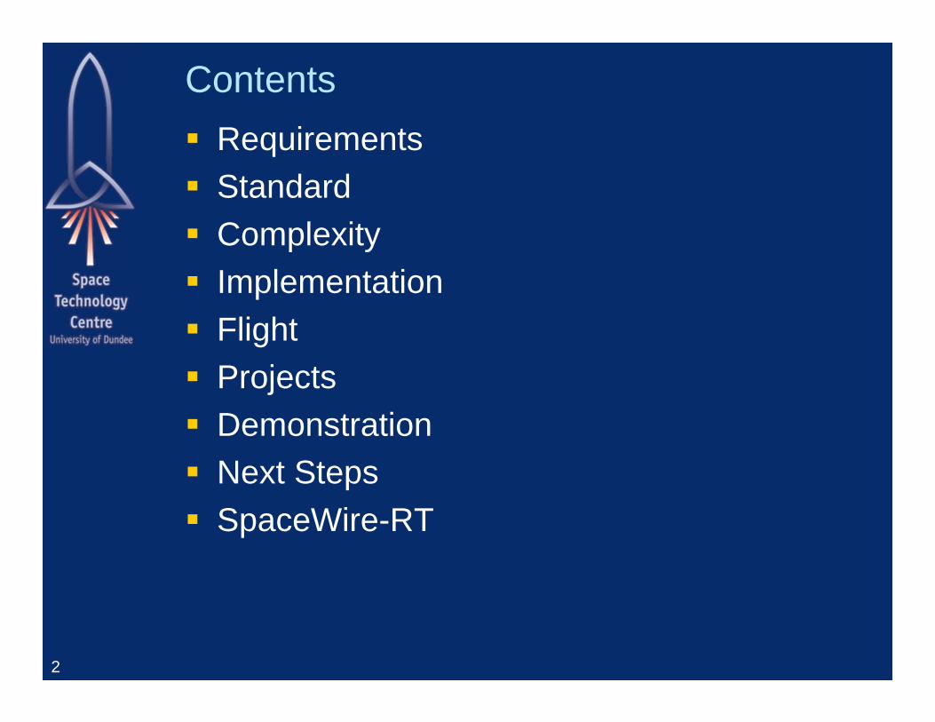
Contents Requirements Standard Complexity Implementation Flight Projects Demonstration Next Steps SpaceWire-RT
2
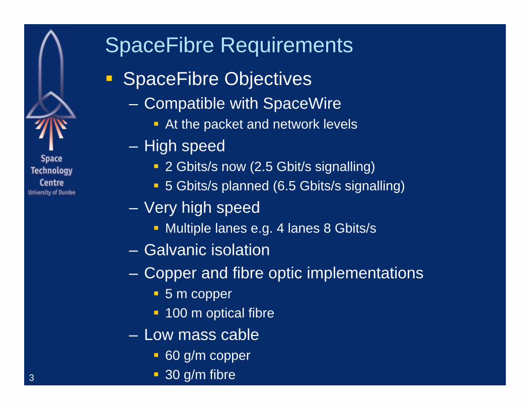
SpaceFibre Requirements SpaceFibre Objectives
– Compatible with SpaceWire At the packet and network levels
– High speed 2 Gbits/s now (2.5 Gbit/s signalling) 5 Gbits/s planned (6.5 Gbits/s signalling)
– Very high speed Multiple lanes e.g. 4 lanes 8 Gbits/s
– Galvanic isolation– Copper and fibre optic implementations
5 m copper 100 m optical fibre
– Low mass cable 60 g/m copper 30 g/m fibre3
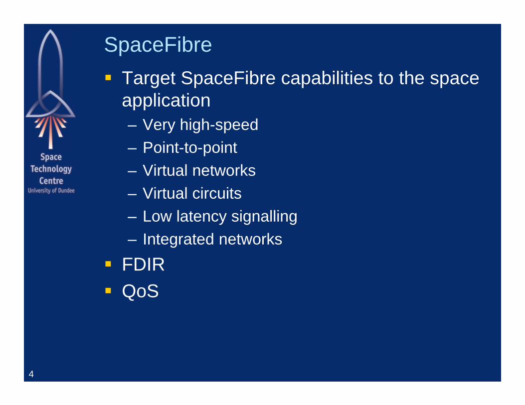
SpaceFibre Target SpaceFibre capabilities to the space
application– Very high-speed – Point-to-point– Virtual networks– Virtual circuits– Low latency signalling– Integrated networks
FDIR QoS
4
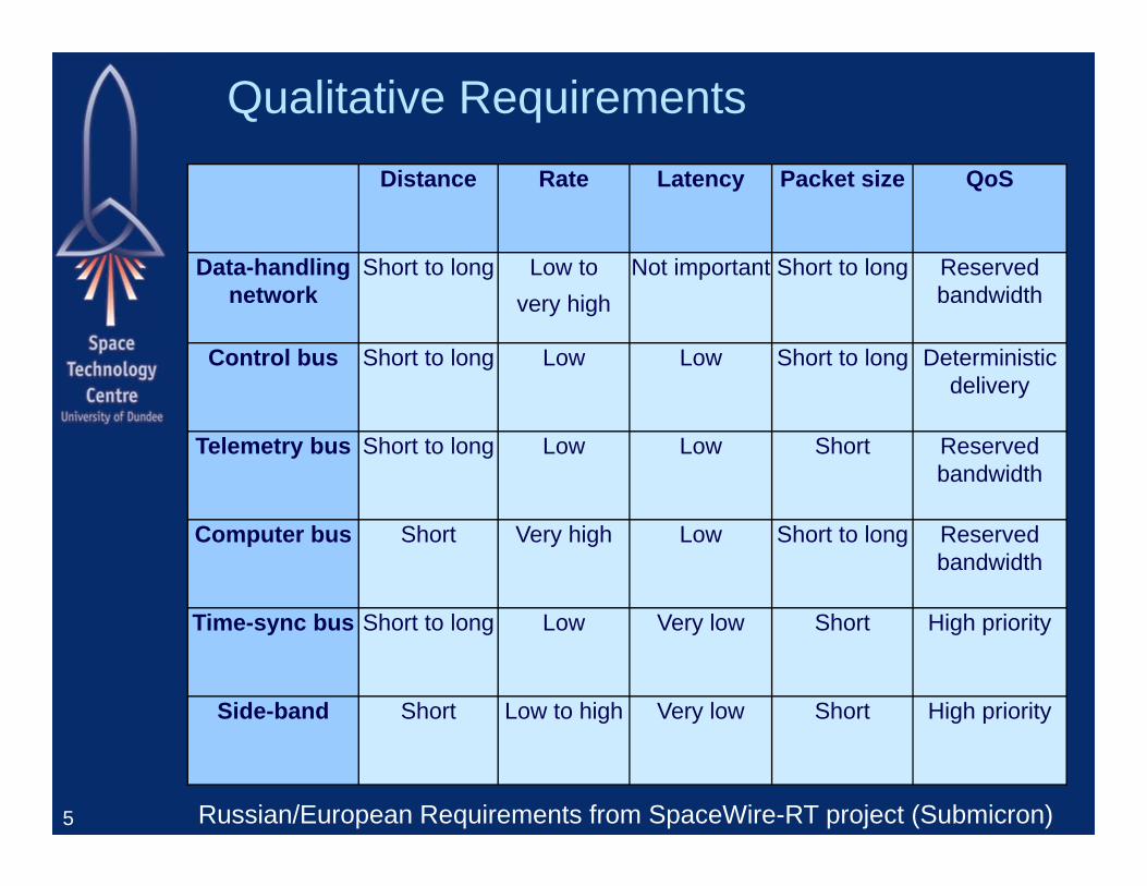
Qualitative RequirementsDistance Rate Latency Packet size QoS
Data-handling network
Short to long Low to very high
Not important Short to long Reserved bandwidth
Control bus Short to long Low Low Short to long Deterministic delivery
Telemetry bus Short to long Low Low Short Reserved bandwidth
Computer bus Short Very high Low Short to long Reserved bandwidth
Time-sync bus Short to long Low Very low Short High priority
Side-band Short Low to high Very low Short High priority
5 Russian/European Requirements from SpaceWire-RT project (Submicron)
VHiSSI(Very High Speed Serial Interfaces)
Set of Requirements for SpaceFibre-HSSI
6

The VHiSSI project has received funding from the European Union Seventh Framework Programme (FP7/2007-2013) under Grant Agreement no. 284389
VHiSSI
7
The Consortium University of Dundee STAR-Dundee ACE-IC RAMON chips IHP ASTRIUM EIT
The VHiSSI project has received funding from the European Union Seventh Framework Programme (FP7/2007-2013) under Grant Agreement no. 284389
VHiSSI
8
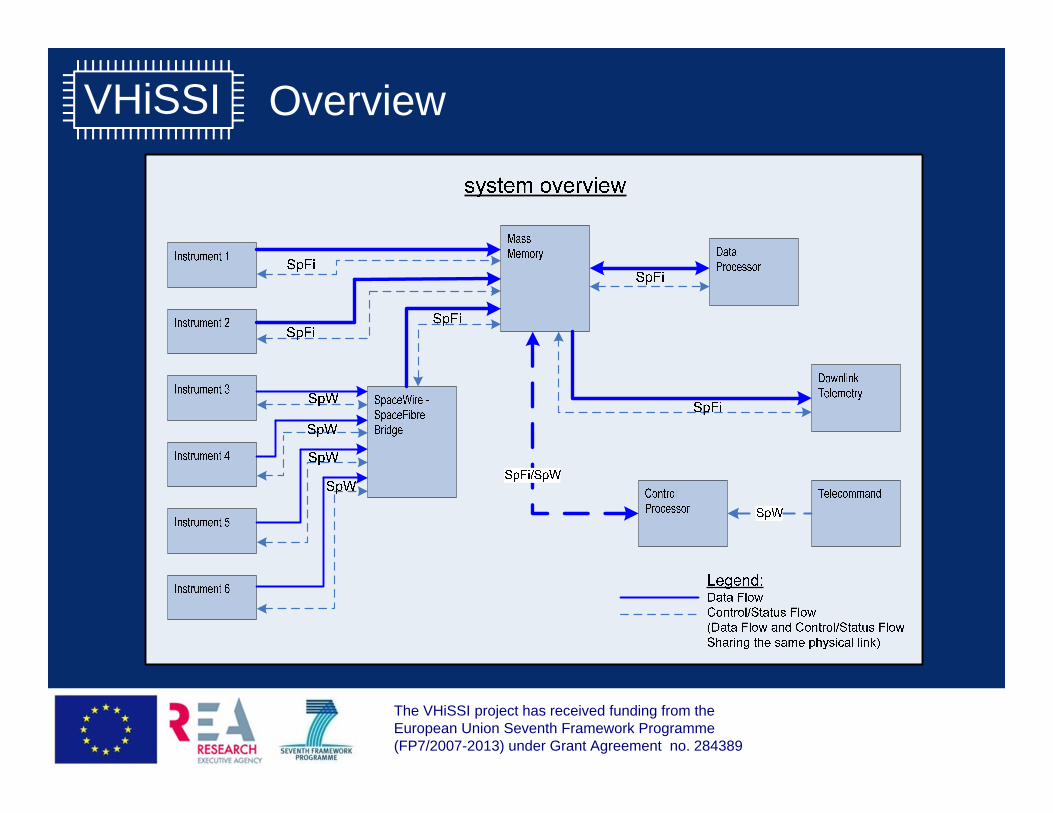
Overview
The VHiSSI project has received funding from the European Union Seventh Framework Programme (FP7/2007-2013) under Grant Agreement no. 284389
VHiSSI
9
Primary Applications SpaceWire to SpaceFibre Bridge Instrument to Mass Memory or Processor Mass Memory from Instruments Mass Memory to Downlink Telemetry Downlink Telemetry from Mass Memory Control Processor controlling instruments and other units Data Processor Array Integrated Avionics Network Long distance control connection for launcher using Fibre
Optics
The VHiSSI project has received funding from the European Union Seventh Framework Programme (FP7/2007-2013) under Grant Agreement no. 284389
VHiSSI
10
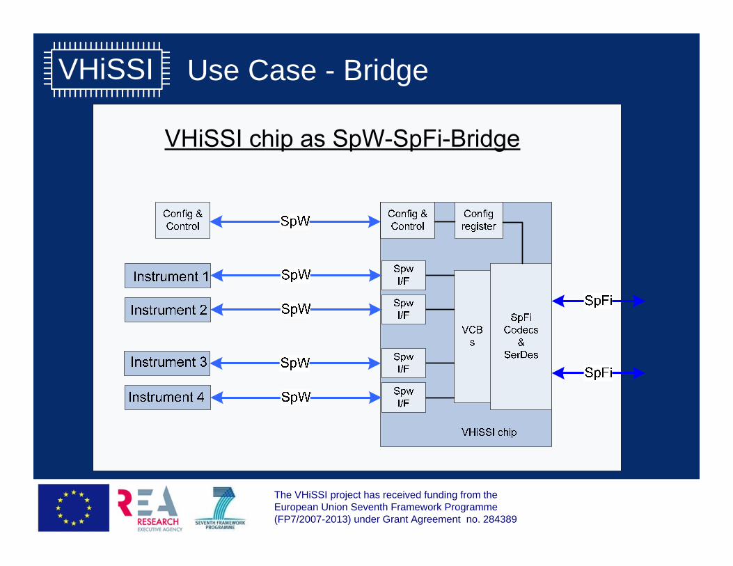
Use Case - Bridge
The VHiSSI project has received funding from the European Union Seventh Framework Programme (FP7/2007-2013) under Grant Agreement no. 284389
VHiSSI
11
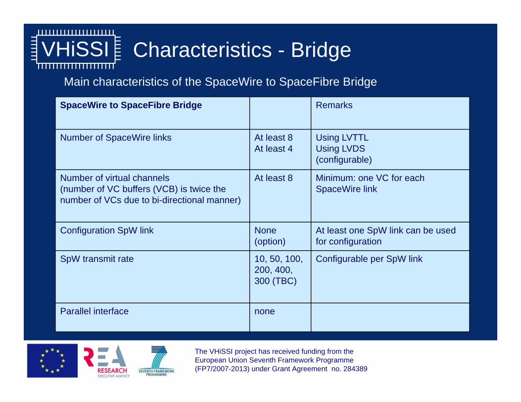
Main characteristics of the SpaceWire to SpaceFibre Bridge
SpaceWire to SpaceFibre Bridge Remarks
Number of SpaceWire links At least 8At least 4
Using LVTTLUsing LVDS(configurable)
Number of virtual channels (number of VC buffers (VCB) is twice the number of VCs due to bi-directional manner)
At least 8 Minimum: one VC for each SpaceWire link
Configuration SpW link None(option)
At least one SpW link can be used for configuration
SpW transmit rate 10, 50, 100, 200, 400, 300 (TBC)
Configurable per SpW link
Parallel interface none
Characteristics - Bridge
The VHiSSI project has received funding from the European Union Seventh Framework Programme (FP7/2007-2013) under Grant Agreement no. 284389
VHiSSI
12
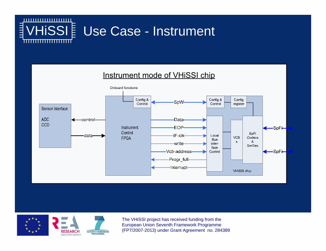
Use Case - Instrument
The VHiSSI project has received funding from the European Union Seventh Framework Programme (FP7/2007-2013) under Grant Agreement no. 284389
VHiSSI
13
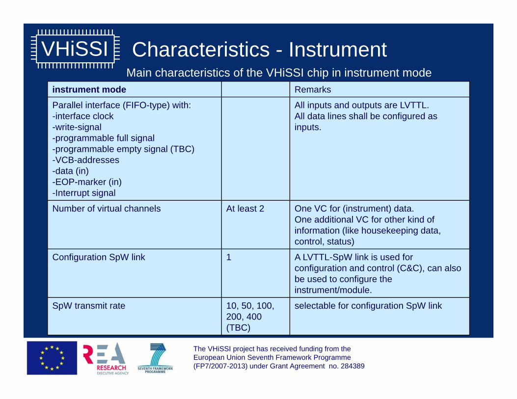
Main characteristics of the VHiSSI chip in instrument modeinstrument mode Remarks
Parallel interface (FIFO-type) with:-interface clock-write-signal-programmable full signal-programmable empty signal (TBC)-VCB-addresses-data (in)-EOP-marker (in)-Interrupt signal
All inputs and outputs are LVTTL.All data lines shall be configured as inputs.
Number of virtual channels At least 2 One VC for (instrument) data. One additional VC for other kind of information (like housekeeping data, control, status)
Configuration SpW link 1 A LVTTL-SpW link is used for configuration and control (C&C), can also be used to configure the instrument/module.
SpW transmit rate 10, 50, 100, 200, 400 (TBC)
selectable for configuration SpW link
Characteristics - Instrument
The VHiSSI project has received funding from the European Union Seventh Framework Programme (FP7/2007-2013) under Grant Agreement no. 284389
VHiSSI
14
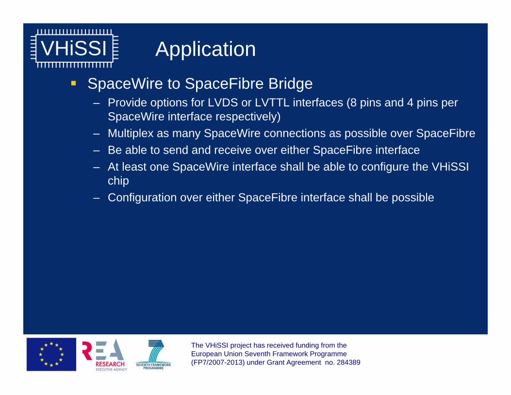
Application SpaceWire to SpaceFibre Bridge
– Provide options for LVDS or LVTTL interfaces (8 pins and 4 pins per SpaceWire interface respectively)
– Multiplex as many SpaceWire connections as possible over SpaceFibre– Be able to send and receive over either SpaceFibre interface– At least one SpaceWire interface shall be able to configure the VHiSSI
chip– Configuration over either SpaceFibre interface shall be possible
The VHiSSI project has received funding from the European Union Seventh Framework Programme (FP7/2007-2013) under Grant Agreement no. 284389
VHiSSI
15
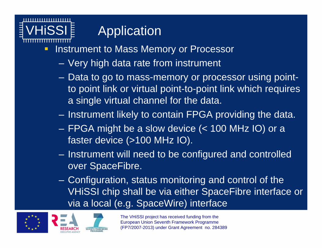
Application Instrument to Mass Memory or Processor
– Very high data rate from instrument– Data to go to mass-memory or processor using point-
to point link or virtual point-to-point link which requires a single virtual channel for the data.
– Instrument likely to contain FPGA providing the data.– FPGA might be a slow device (< 100 MHz IO) or a
faster device (>100 MHz IO).– Instrument will need to be configured and controlled
over SpaceFibre.– Configuration, status monitoring and control of the
VHiSSI chip shall be via either SpaceFibre interface or via a local (e.g. SpaceWire) interface
The VHiSSI project has received funding from the European Union Seventh Framework Programme (FP7/2007-2013) under Grant Agreement no. 284389
VHiSSI
16
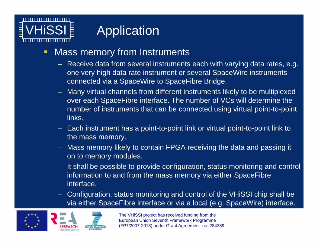
Application Mass memory from Instruments
– Receive data from several instruments each with varying data rates, e.g. one very high data rate instrument or several SpaceWire instruments connected via a SpaceWire to SpaceFibre Bridge.
– Many virtual channels from different instruments likely to be multiplexed over each SpaceFibre interface. The number of VCs will determine the number of instruments that can be connected using virtual point-to-point links.
– Each instrument has a point-to-point link or virtual point-to-point link to the mass memory.
– Mass memory likely to contain FPGA receiving the data and passing it on to memory modules.
– It shall be possible to provide configuration, status monitoring and control information to and from the mass memory via either SpaceFibre interface.
– Configuration, status monitoring and control of the VHiSSI chip shall be via either SpaceFibre interface or via a local (e.g. SpaceWire) interface.
SpaceFibre Standard
17
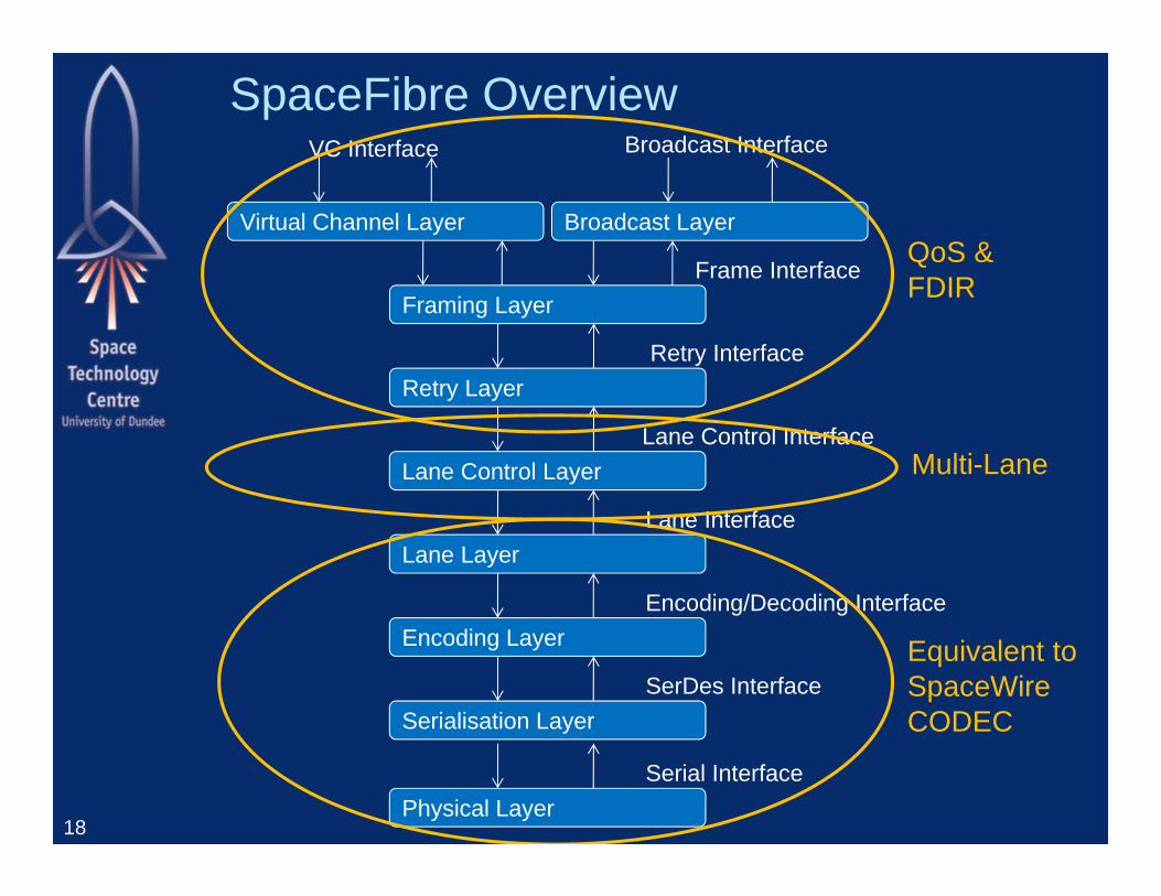
SpaceFibre Overview
18
Retry InterfaceRetry Layer
Encoding/Decoding InterfaceEncoding Layer
SerDes InterfaceSerialisation Layer
Virtual Channel Layer
VC Interface
Serial InterfacePhysical Layer
Lane Control InterfaceLane Control Layer
Lane InterfaceLane Layer
Broadcast Interface
Broadcast Layer
Framing LayerFrame Interface
Equivalent toSpaceWireCODEC
QoS &FDIR
Multi-Lane
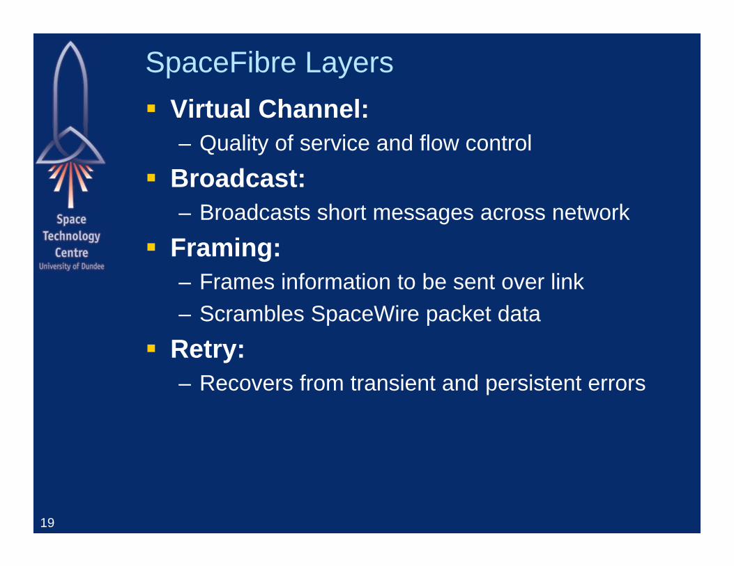
SpaceFibre Layers Virtual Channel:
– Quality of service and flow control Broadcast:
– Broadcasts short messages across network Framing:
– Frames information to be sent over link– Scrambles SpaceWire packet data
Retry:– Recovers from transient and persistent errors
19
SpaceFibre Layers
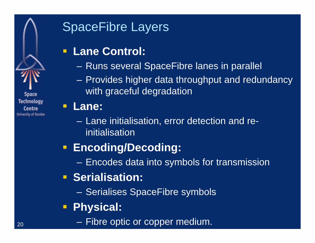
Lane Control:– Runs several SpaceFibre lanes in parallel– Provides higher data throughput and redundancy
with graceful degradation Lane:
– Lane initialisation, error detection and re-initialisation
Encoding/Decoding:– Encodes data into symbols for transmission
Serialisation:– Serialises SpaceFibre symbols
Physical:– Fibre optic or copper medium.20
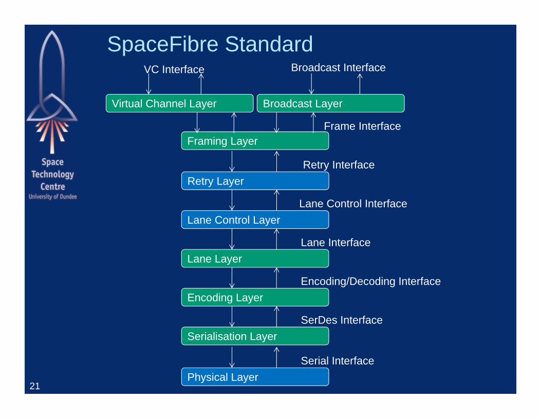
SpaceFibre Standard
21
Retry InterfaceRetry Layer
Encoding/Decoding InterfaceEncoding Layer
SerDes InterfaceSerialisation Layer
Virtual Channel Layer
VC Interface
Serial InterfacePhysical Layer
Lane Control InterfaceLane Control Layer
Lane InterfaceLane Layer
Broadcast Interface
Broadcast Layer
Framing LayerFrame Interface
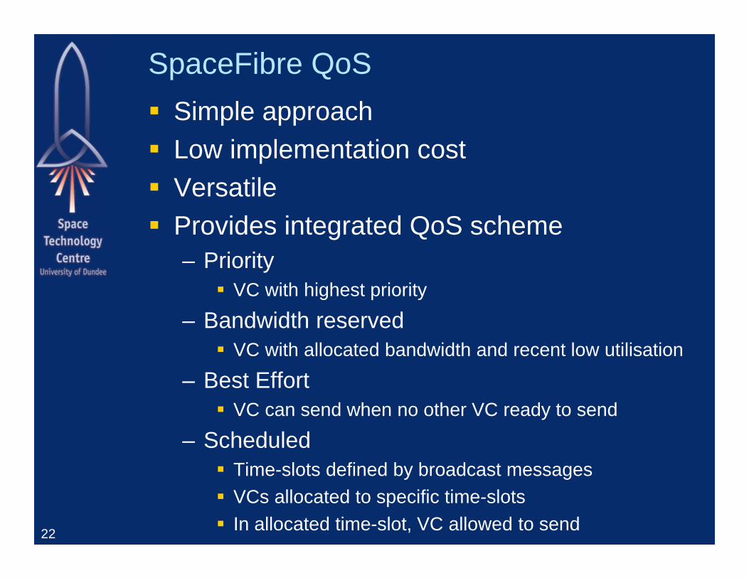
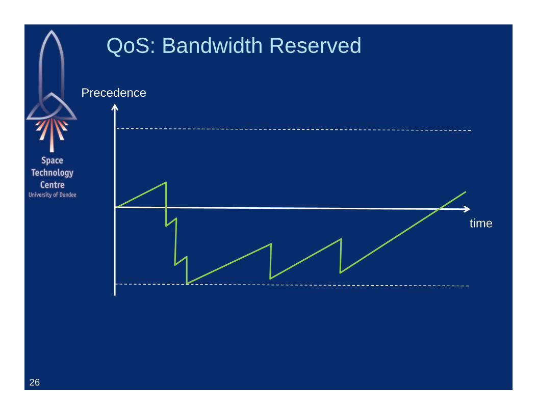
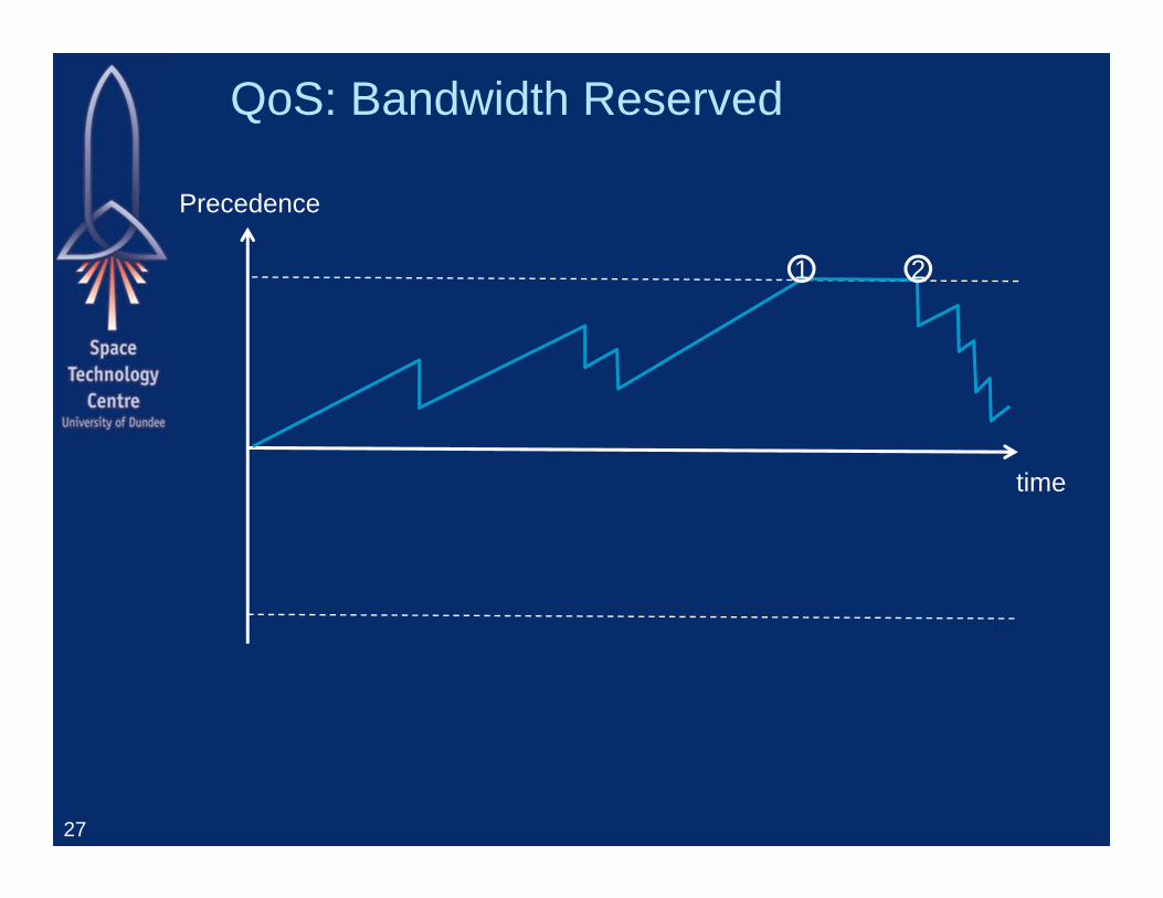
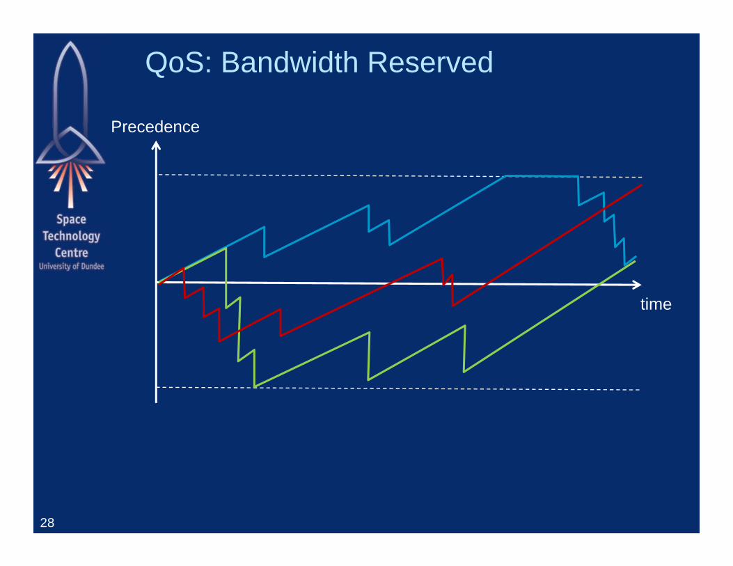
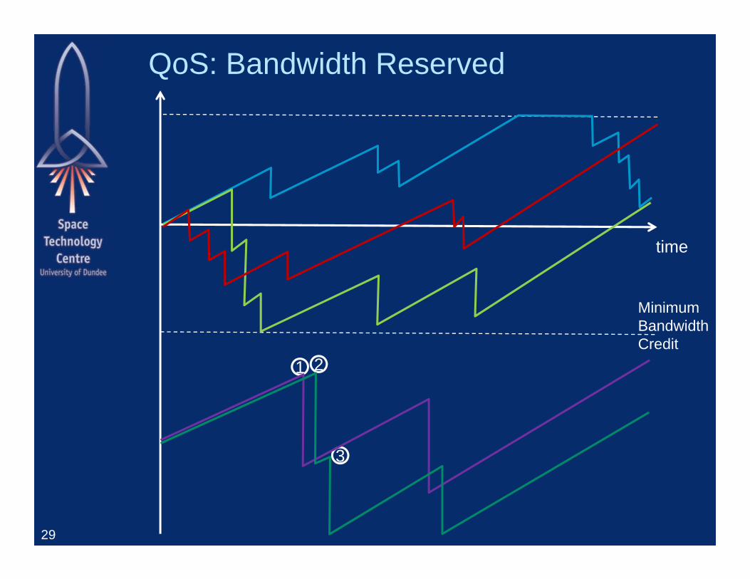
SpaceFibre QoS Simple approach Low implementation cost Versatile Provides integrated QoS scheme
– Priority VC with highest priority
– Bandwidth reserved VC with allocated bandwidth and recent low utilisation
– Best Effort VC can send when no other VC ready to send
– Scheduled Time-slots defined by broadcast messages VCs allocated to specific time-slots In allocated time-slot, VC allowed to send22
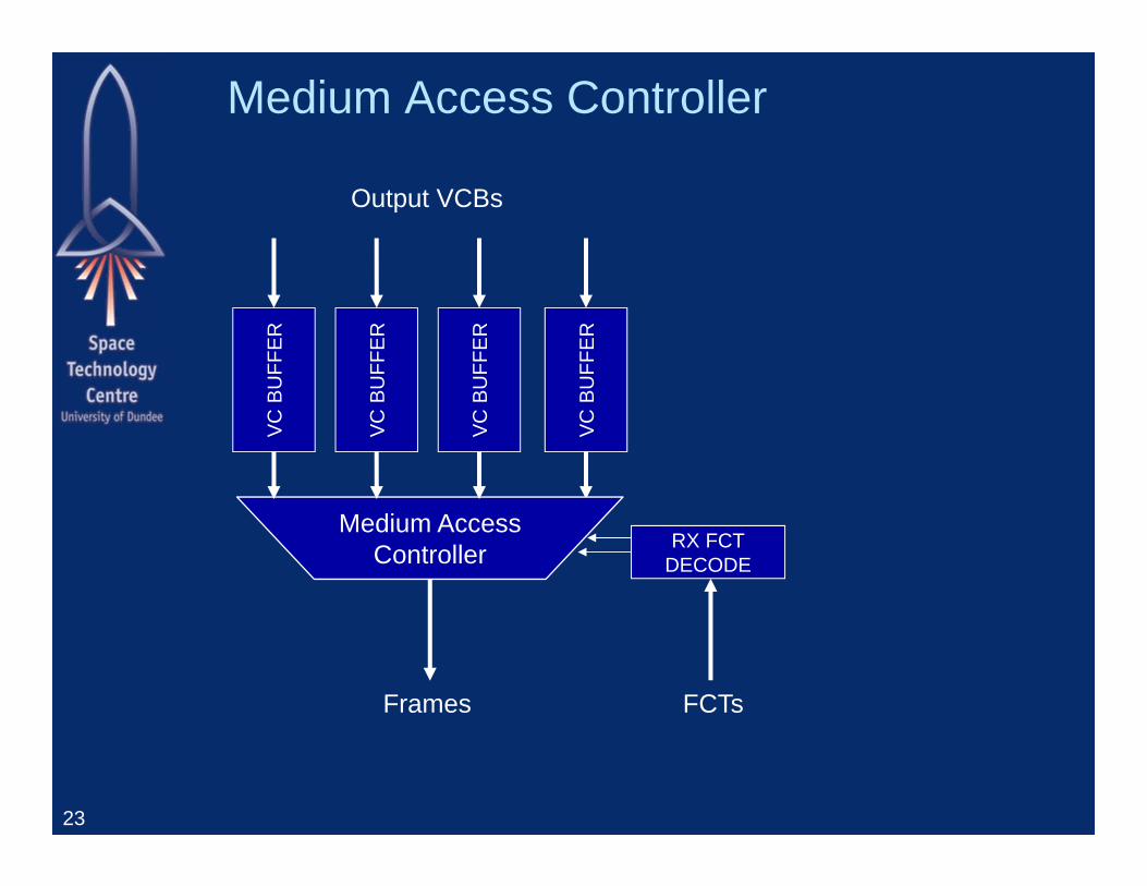
Medium Access Controller
23
Frames FCTs
VC B
UFF
ER
RX FCTDECODE
Output VCBs
Medium AccessController
VC B
UFF
ER
VC B
UFF
ER
VC B
UFF
ER
Medium Access Controller Determines
– Output VCB permitted to send next frame Depends on:
– Which output VCBs have data to send– Which input VCBs at other end of link have room – Arbitration or QoS policy in force for each virtual
channel
24
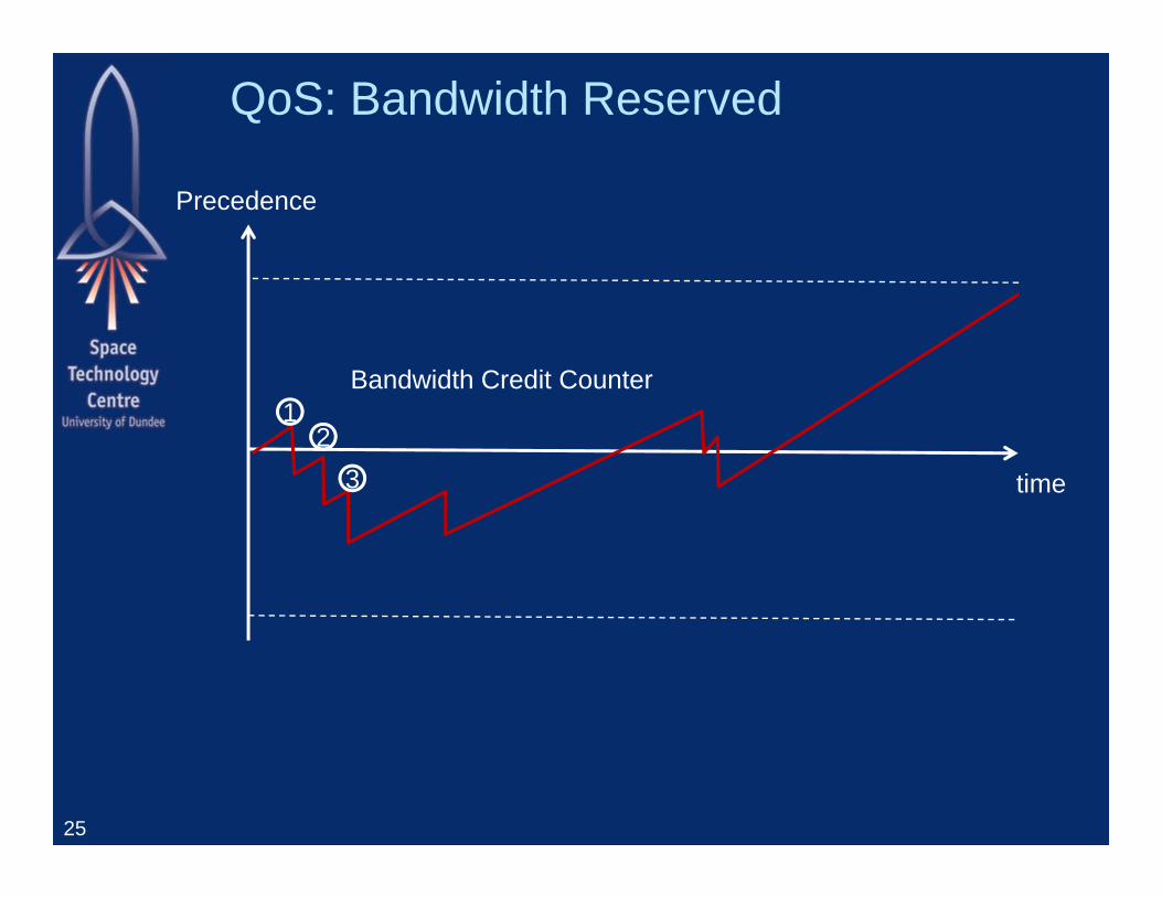
QoS: Bandwidth Reserved
25
time
12
3
Precedence
Bandwidth Credit Counter
QoS: Bandwidth Reserved
26
time
Precedence
QoS: Bandwidth Reserved
27
time
1 2
Precedence
QoS: Bandwidth Reserved
28
time
Precedence
QoS: Bandwidth Reserved
29
time
1 2
3
MinimumBandwidthCredit
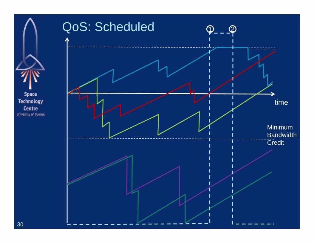
QoS: Scheduled
30
time
1 2
MinimumBandwidthCredit
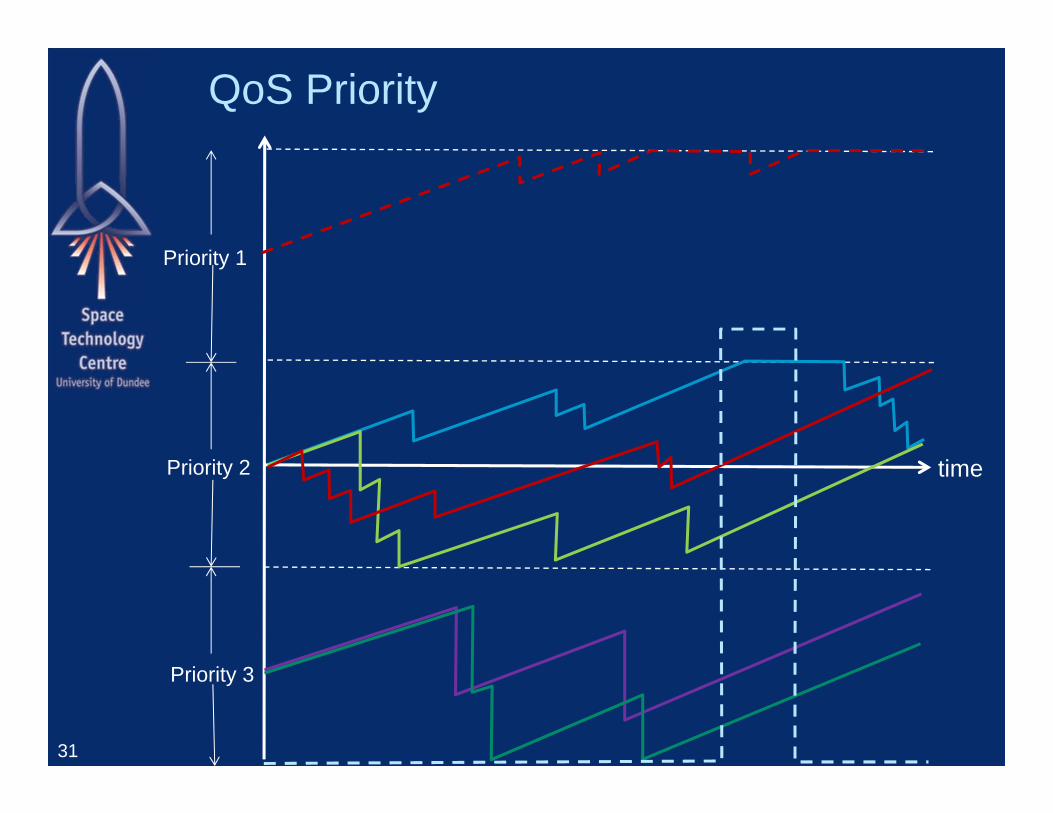
QoS Priority
31
time
Priority 1
Priority 2
Priority 3
FDIR Support in QoS Bandwidth credit counter also supports fault
detection:– Excessive bandwidth utilisation
When BW credit counter reaches negative limit
– Under utilisation of allocated bandwidth When BW credit counter stays at maximum limit for long
period of time
Can be used to detect– Babbling idiots– Faulty units
All provided with simple, low cost, mechanism
32
SpaceFibre Complexity
33
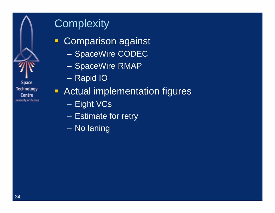
Complexity Comparison against
– SpaceWire CODEC– SpaceWire RMAP– Rapid IO
Actual implementation figures– Eight VCs– Estimate for retry– No laning
34
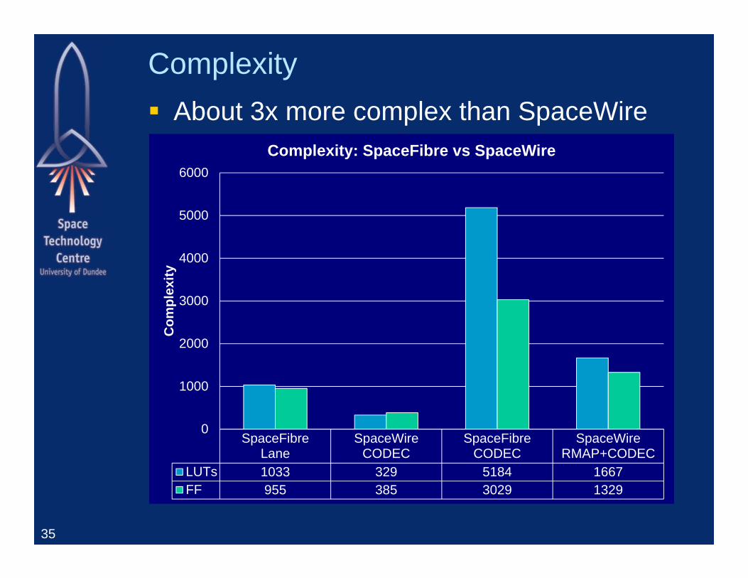
Complexity About 3x more complex than SpaceWire
35
SpaceFibreLane
SpaceWireCODEC
SpaceFibreCODEC
SpaceWireRMAP+CODEC
LUTs 1033 329 5184 1667FF 955 385 3029 1329
0
1000
2000
3000
4000
5000
6000C
ompl
exity
Complexity: SpaceFibre vs SpaceWire
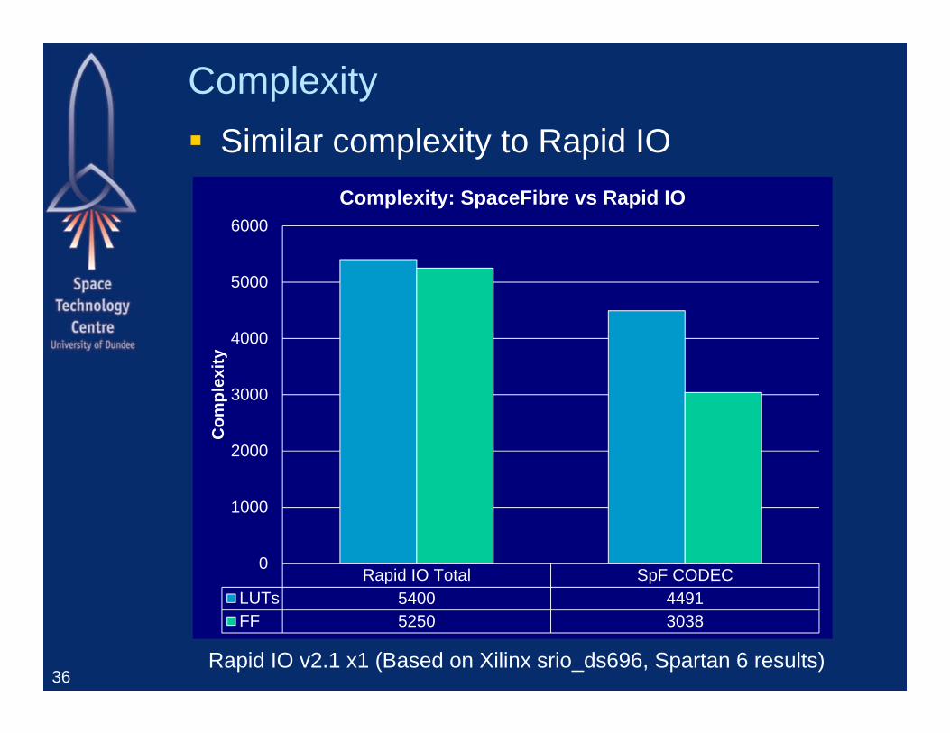
Complexity Similar complexity to Rapid IO
36
Rapid IO Total SpF CODECLUTs 5400 4491FF 5250 3038
0
1000
2000
3000
4000
5000
6000C
ompl
exity
Complexity: SpaceFibre vs Rapid IO
Rapid IO v2.1 x1 (Based on Xilinx srio_ds696, Spartan 6 results)
Implementing SpaceFibre
37
Implementation Physical Layer
– Examples– Copper cable/connectors– Fibre Optics
CODEC IP Core Test and development equipment
38
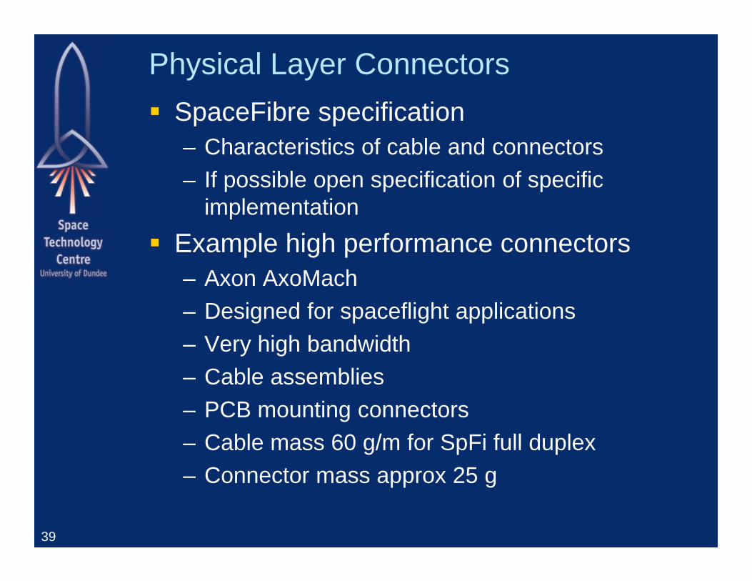
Physical Layer Connectors SpaceFibre specification
– Characteristics of cable and connectors– If possible open specification of specific
implementation Example high performance connectors
– Axon AxoMach– Designed for spaceflight applications– Very high bandwidth– Cable assemblies– PCB mounting connectors– Cable mass 60 g/m for SpFi full duplex– Connector mass approx 25 g
39
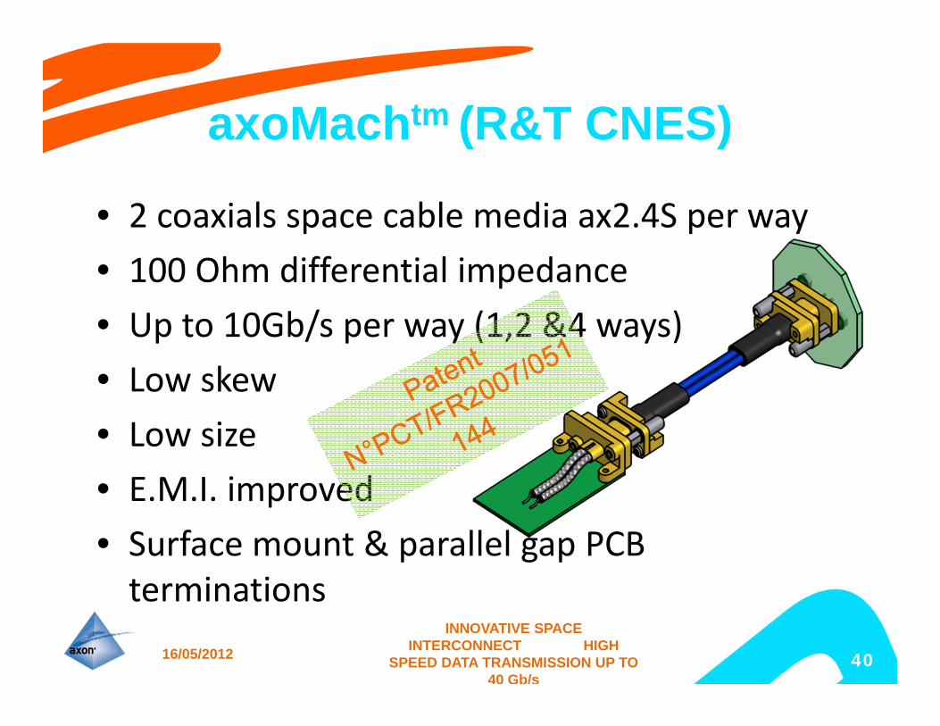
axoMachtm (R&T CNES)
• 2 coaxials space cable media ax2.4S per way• 100 Ohm differential impedance• Up to 10Gb/s per way (1,2 &4 ways)• Low skew• Low size• E.M.I. improved• Surface mount & parallel gap PCB terminations
16/05/2012
INNOVATIVE SPACE INTERCONNECT HIGH
SPEED DATA TRANSMISSION UP TO 40 Gb/s
40
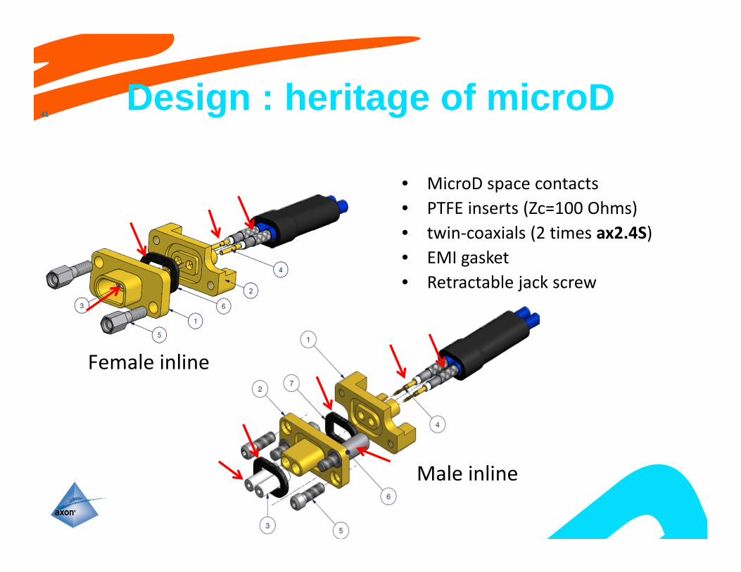
Design : heritage of microD
• MicroD space contacts• PTFE inserts (Zc=100 Ohms)• twin‐coaxials (2 times ax2.4S)• EMI gasket• Retractable jack screw
41
INNOVATIVE SPACE INTERCONNECT HIGH
SPEED DATA TRANSMISSION UP TO 40 Gb/s
Female inline
Male inline
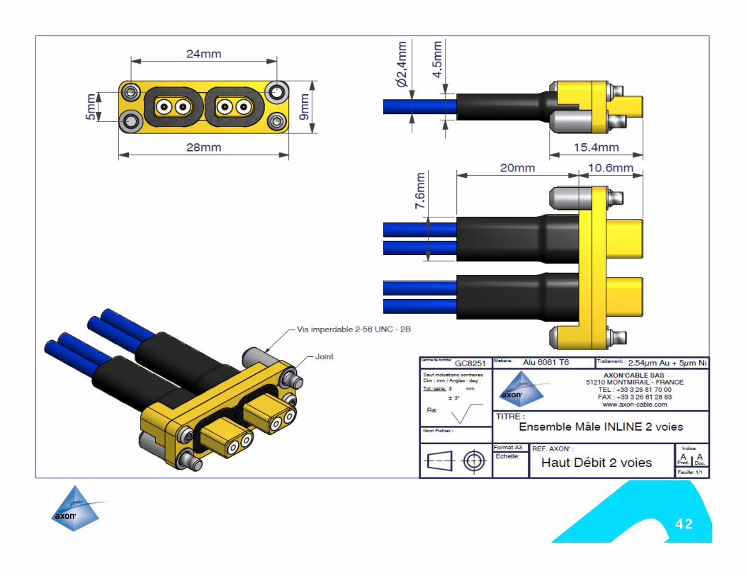
42
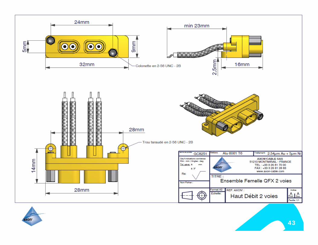
43
ESA Presentation | DD/MM/YYYY | Slide 44
ESA UNCLASSIFIED – For Official Use
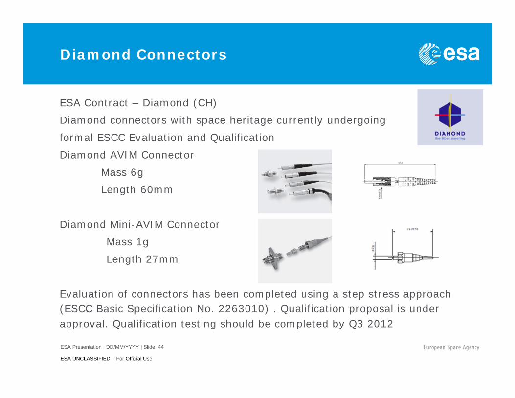
Diamond Connectors
ESA Contract – Diamond (CH)Diamond connectors with space heritage currently undergoing formal ESCC Evaluation and Qualification Diamond AVIM Connector
Mass 6gLength 60mm
Diamond Mini-AVIM ConnectorMass 1gLength 27mm
Evaluation of connectors has been completed using a step stress approach (ESCC Basic Specification No. 2263010) . Qualification proposal is under approval. Qualification testing should be completed by Q3 2012
ESA Presentation | DD/MM/YYYY | Slide 45
ESA UNCLASSIFIED – For Official Use
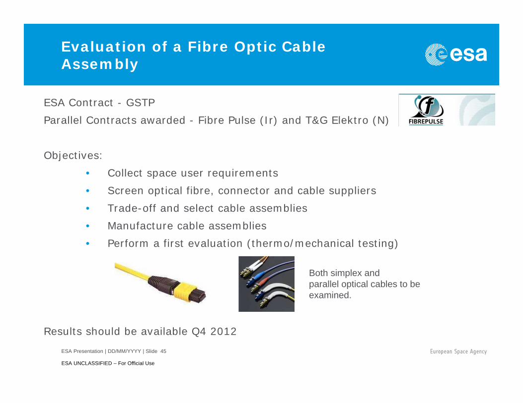
Evaluation of a Fibre Optic Cable Assembly
ESA Contract - GSTP Parallel Contracts awarded - Fibre Pulse (Ir) and T&G Elektro (N)
Objectives:• Collect space user requirements• Screen optical fibre, connector and cable suppliers• Trade-off and select cable assemblies• Manufacture cable assemblies• Perform a first evaluation (thermo/mechanical testing)
Results should be available Q4 2012
Both simplex and parallel optical cables to be examined.
ESA Presentation | DD/MM/YYYY | Slide 46
ESA UNCLASSIFIED – For Official Use
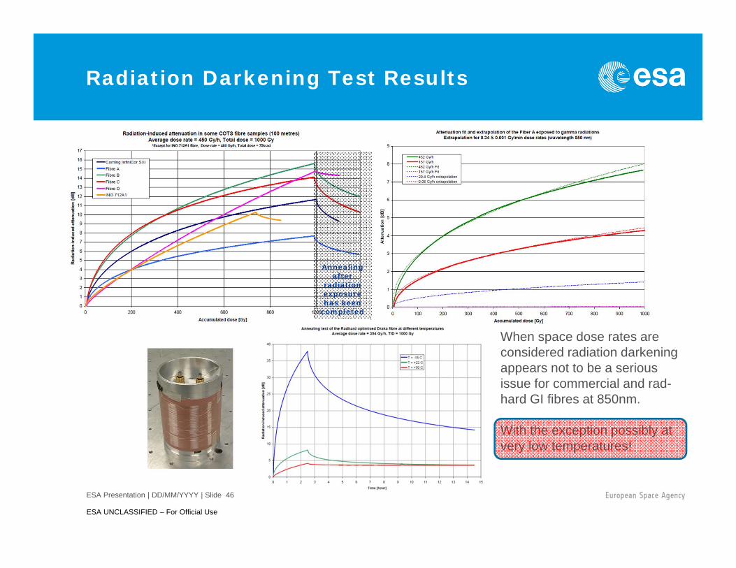
Radiation Darkening Test Results
Annealingafter
radiation exposure has been
completed
When space dose rates are considered radiation darkening appears not to be a serious issue for commercial and rad-hard GI fibres at 850nm.
With the exception possibly at very low temperatures!
ESA Presentation | DD/MM/YYYY | Slide 47
ESA UNCLASSIFIED – For Official Use
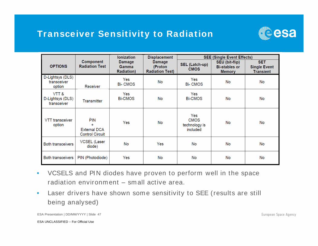
Transceiver Sensitivity to Radiation
• VCSELS and PIN diodes have proven to perform well in the space radiation environment – small active area.
• Laser drivers have shown some sensitivity to SEE (results are still being analysed)
ESA Presentation | DD/MM/YYYY | Slide 48
ESA UNCLASSIFIED – For Official Use
Space Fibre 2
ESA Contract - ARTES 5.1Prime: Patria Aviation Oy Systems (Fin)Subcontractors: VTT (Fin) and Dlightsys (F) - transceiver manufacture
Alter (E) – optical component test houseThales Alenia Space (F) - end user
Objective:To develop an Engineering Model (EM) of a high speed fibre-optic transceiver (>6.25Gbps) for use onboard telecom satellites consolidated through testing.
Test Readiness Review held 20.04.2012Mechanical, thermal, life test, outgassing, TID, end-user and SpaceWire network tests to be performed on Dlightsys and VTT modules.
Test results should be available by Q4(Patria to provide further details of progress)
ESA Presentation | DD/MM/YYYY | Slide 49
ESA UNCLASSIFIED – For Official Use
Planned Space Environment Testing on Space Fibre 2 Modules
• Random Vibration: 50 g rms (100-2000Hz)• Shock Testing: 3000g at 10kHz (5 shocks per axis)• Life Test: 2000 hours at Max. Case temperature• Thermal Cycling: -55°C … +125°C (operational at least 500 cycles)• Radiation Testing
• Gamma TID 100 krads• Single Event Effects - Heavy Ion Testing (different energy levels
up to 15, 35 and 70MeV)• Proton 1012 Fluence
• Material Outgassing• Leak Test• Moisture Resistance Test• ESD
ESA Presentation | DD/MM/YYYY | Slide 50
ESA UNCLASSIFIED – For Official Use
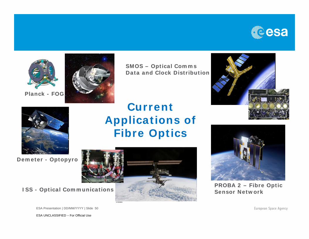
Current Applications of
Fibre Optics
SMOS – Optical CommsData and Clock Distribution
PROBA 2 – Fibre Optic Sensor NetworkISS - Optical Communications
Demeter - Optopyro
Planck - FOG
SpaceFibre CODEC SpaceFibre CODEC IP
– Generic number of virtual channels– Broadcast channels– Full QoS support– FDIR– Designed to operate with several SerDes
Developed by UoD and STAR-Dundee Will be available from ESA
– For use on ESA missions Will be available from STAR-Dundee
– For other missions Alpha customer testing in summer 2012
51
SpaceFibre Test and Development Kit SpaceFibre to USB interface SpaceFibre to PCIe interface SpaceFibre Link Analyser
– USB or PCIe versions SpaceFibre EGSE
– USB or PCIe versions
52
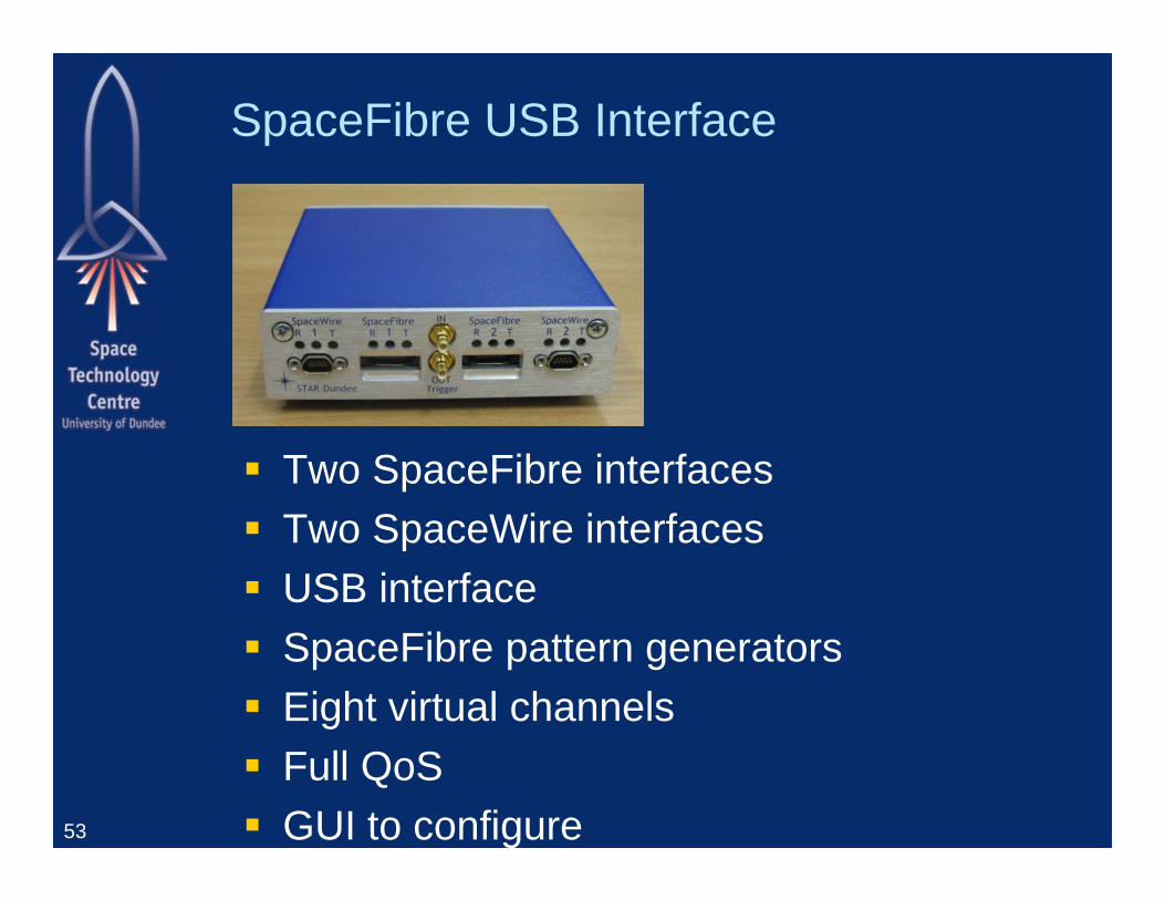
SpaceFibre USB Interface
Two SpaceFibre interfaces Two SpaceWire interfaces USB interface SpaceFibre pattern generators Eight virtual channels Full QoS GUI to configure53
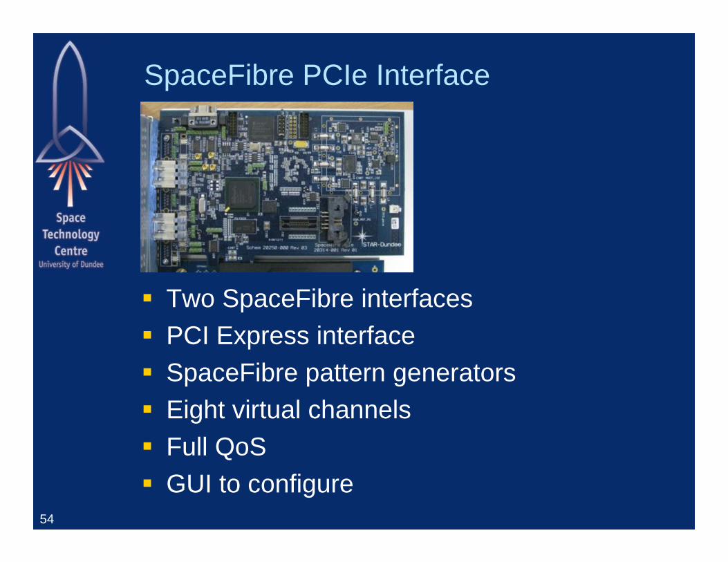
SpaceFibre PCIe Interface
Two SpaceFibre interfaces PCI Express interface SpaceFibre pattern generators Eight virtual channels Full QoS GUI to configure
54
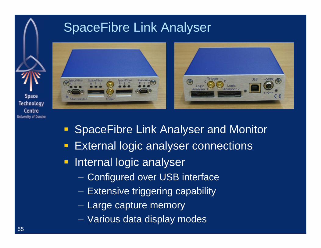
SpaceFibre Link Analyser
SpaceFibre Link Analyser and Monitor External logic analyser connections Internal logic analyser
– Configured over USB interface– Extensive triggering capability– Large capture memory– Various data display modes
55
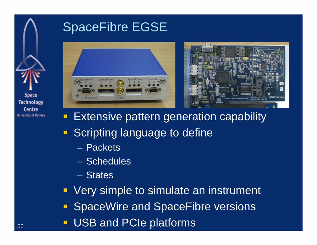
SpaceFibre EGSE
Extensive pattern generation capability Scripting language to define
– Packets– Schedules– States
Very simple to simulate an instrument SpaceWire and SpaceFibre versions USB and PCIe platforms56
Spaceflight Capable Designs
57
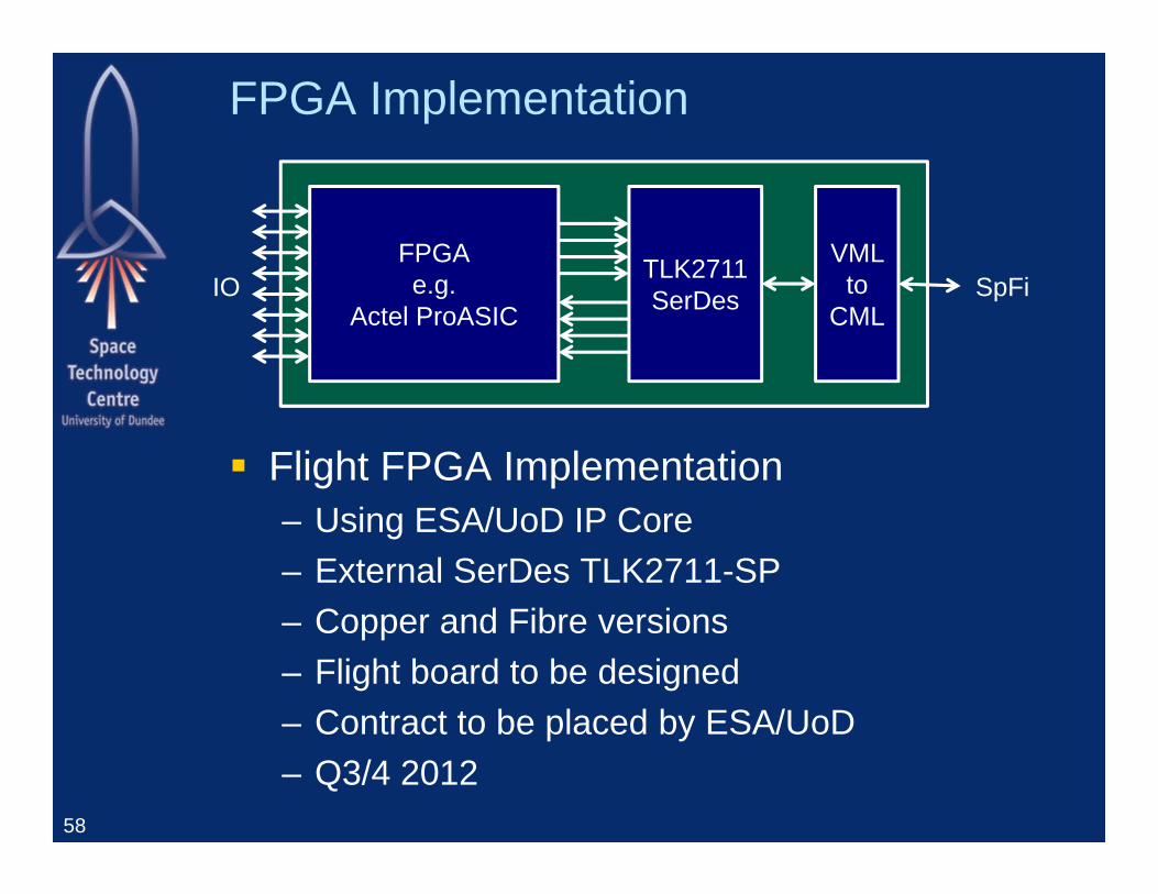
FPGA Implementation
Flight FPGA Implementation– Using ESA/UoD IP Core– External SerDes TLK2711-SP– Copper and Fibre versions– Flight board to be designed– Contract to be placed by ESA/UoD– Q3/4 2012
58
FPGAe.g.
Actel ProASIC
TLK2711SerDes
VML to
CMLSpFiIO
The VHiSSI project has received funding from the European Union Seventh Framework Programme (FP7/2007-2013) under Grant Agreement no. 284389
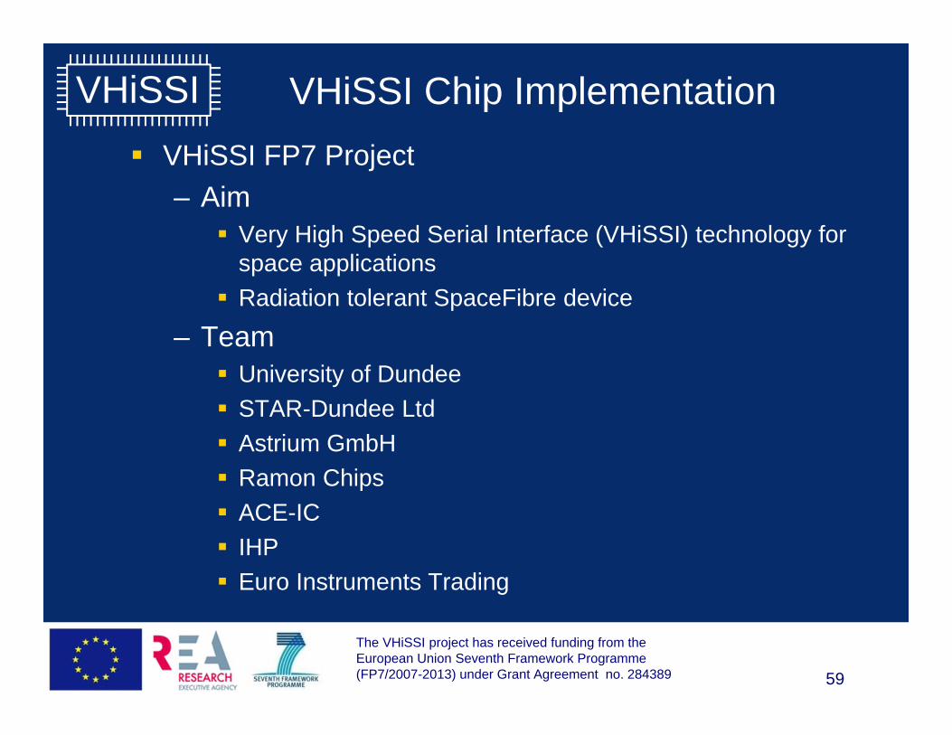
VHiSSI VHiSSI Chip Implementation VHiSSI FP7 Project
– Aim Very High Speed Serial Interface (VHiSSI) technology for
space applications Radiation tolerant SpaceFibre device
– Team University of Dundee STAR-Dundee Ltd Astrium GmbH Ramon Chips ACE-IC IHP Euro Instruments Trading
59
The VHiSSI project has received funding from the European Union Seventh Framework Programme (FP7/2007-2013) under Grant Agreement no. 284389
VHiSSI VHiSSI Chip Implementation VHiSSI chip specification
– High speed serial interface 2.5 Gbits/s (at least)
– Fully integrated SpaceFibre interface Including QoS and FDIR
– Two SpaceFibre ports– Low power– Small size
20 x 14 mm
– Radiation tolerant– ITAR free technology
60
The VHiSSI project has received funding from the European Union Seventh Framework Programme (FP7/2007-2013) under Grant Agreement no. 284389
VHiSSI VHiSSI Chip Implementation VHiSSI chip modes
– SpaceWire to SpaceFibre Several SpaceWire interfaces Connected to SpaceFibre virtual channels Mix of LVDS and LVTTL interfaces
– Various other interface modes Designed for simple interfacing to
– FPGA– Memory– Processors
61
The VHiSSI project has received funding from the European Union Seventh Framework Programme (FP7/2007-2013) under Grant Agreement no. 284389
VHiSSI VHiSSI Chip Implementation VHiSSI Chip Implementation
62
ESA Projects Using SpaceFibre
63
This
doc
umen
t is
the
prop
erty
of A
striu
m. I
t sha
ll no
t be
com
mun
icat
ed to
third
par
ties
with
out p
rior w
ritte
n ag
reem
ent.
Its c
onte
nt s
hall
not b
e di
sclo
sed.
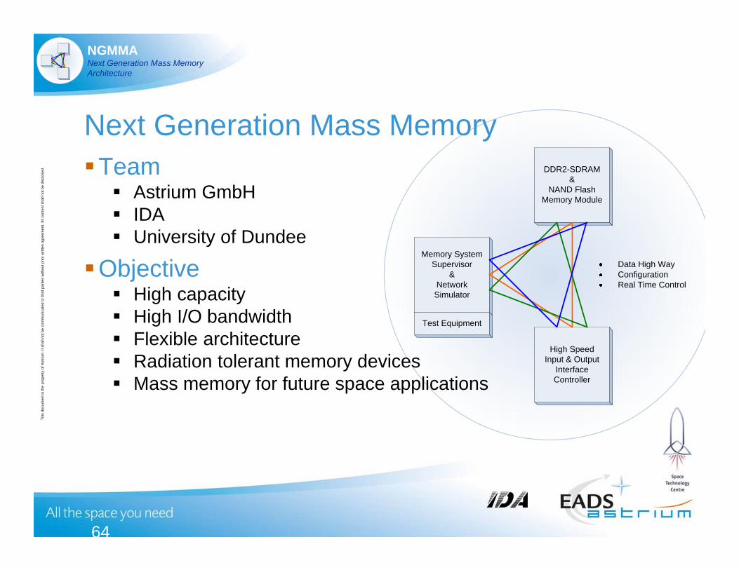
NGMMANext Generation Mass MemoryArchitecture
DDR2-SDRAM&
NAND FlashMemory Module
High SpeedInput & Output
Interface Controller
Memory System Supervisor
&Network
Simulator
Data High WayConfigurationReal Time Control
Test Equipment
Next Generation Mass MemoryTeam Astrium GmbH IDA University of Dundee
Objective High capacity High I/O bandwidth Flexible architecture Radiation tolerant memory devices Mass memory for future space applications
64
This
doc
umen
t is
the
prop
erty
of A
striu
m. I
t sha
ll no
t be
com
mun
icat
ed to
third
par
ties
with
out p
rior w
ritte
n ag
reem
ent.
Its c
onte
nt s
hall
not b
e di
sclo
sed.
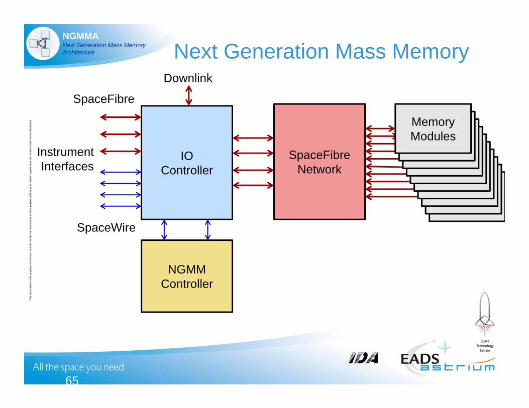
NGMMANext Generation Mass MemoryArchitecture Next Generation Mass Memory
65
SpaceFibreNetwork
IOController
SpaceFibre
SpaceWire
NGMMController
MemoryModules
MemoryModules
MemoryModules
MemoryModules
MemoryModules
MemoryModules
MemoryModules
MemoryModules
MemoryModules
MemoryModules
InstrumentInterfaces
Downlink
High Performance COTS based Computer step II ESA led activity (GSTP funded)
Aims to build a demonstrator of a COTS based payload data processor
Planned end of study : December 2013
Aims at defining a framework that can accommodate a range of COTS processors
Date - 66
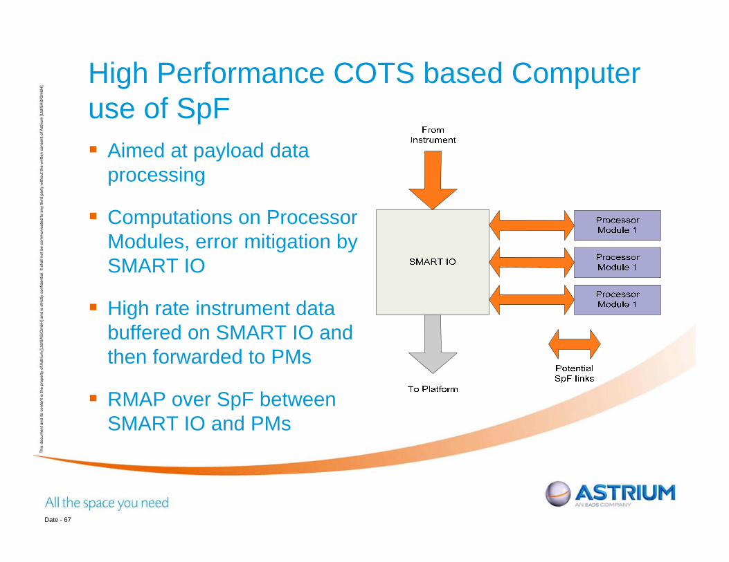
High Performance COTS based Computer use of SpF Aimed at payload data
processing
Computations on Processor Modules, error mitigation by SMART IO
High rate instrument data buffered on SMART IO and then forwarded to PMs
RMAP over SpF between SMART IO and PMs
Date - 67
High Processing Power DSP Team
– Astrium Ltd– STAR-Dundee Ltd– CG Space
Objective– DSP system for space applications– High performance– Wide bandwidth interfaces– Flexible interfaces
SpaceFibre SpaceWire GPIO
68
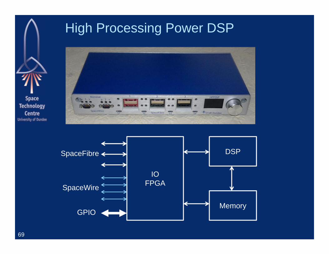
High Processing Power DSP
69
DSP
IOFPGA
Memory
SpaceFibre
SpaceWire
GPIO
Japanese SpaceFibre projects NEC and Melco are both developing
SpaceFibre interfaces Will be tested for interoperability with UoD
– in November 2012
70
Demonstration
71
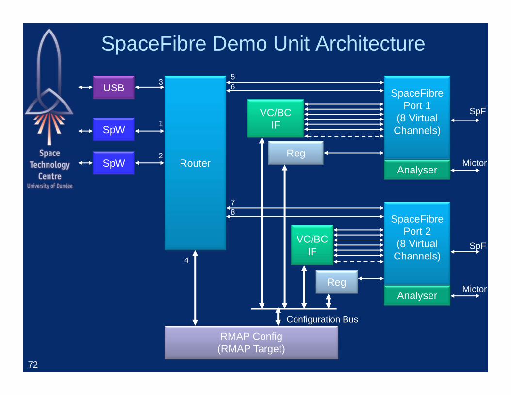
SpaceFibre Demo Unit Architecture
72
VC/BCIF
Reg
USB 3
Router
SpW
SpW
1
2
56
SpaceFibrePort 1
(8 Virtual Channels)
SpF
AnalyserMictor
VC/BCIF
SpaceFibrePort 2
(8 Virtual Channels)
Reg
78
Analyser
SpF
Mictor
RMAP Config(RMAP Target)
4
Configuration Bus
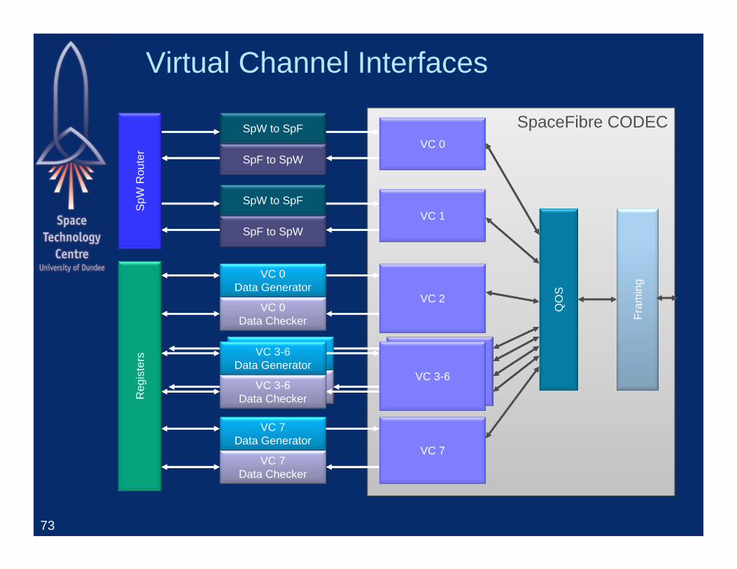
Virtual Channel Interfaces
73
SpaceFibre CODEC
VC 3-6Data Generator
VC 3-6Data Checker
VC 3-6
VC 7Data Generator
VC 7Data Checker
VC 7
Reg
iste
rs
QO
S
Fram
ing
SpW to SpF
SpF to SpWVC 0
SpW to SpF
SpF to SpWVC 1
VC 0Data Generator
VC 0Data Checker
VC 2
SpW
Rou
ter
VC 3-6Data Generator
VC 3-6Data Checker
VC 3-6
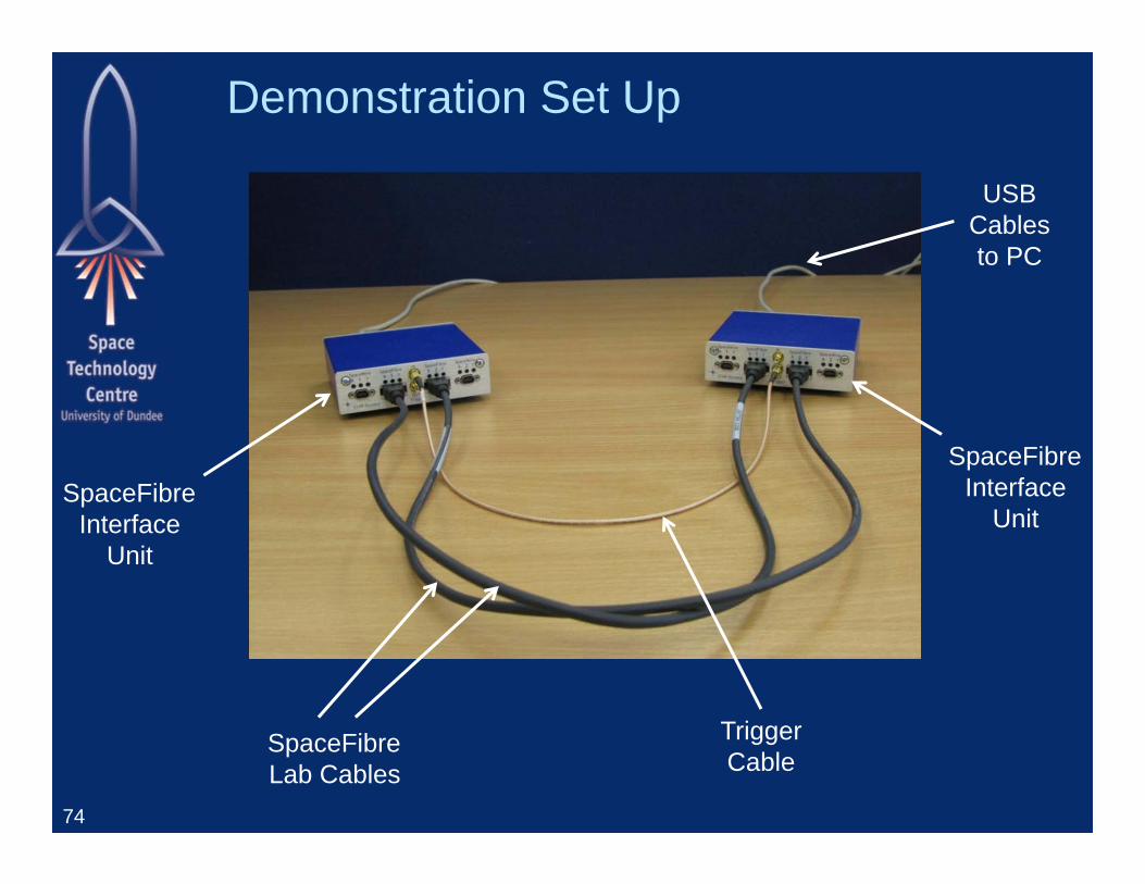
Demonstration Set Up
74
SpaceFibreInterface
Unit
SpaceFibreInterface
Unit
SpaceFibreLab Cables
TriggerCable
USBCablesto PC
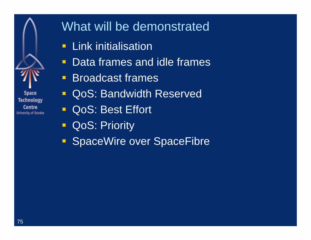
What will be demonstrated Link initialisation Data frames and idle frames Broadcast frames QoS: Bandwidth Reserved QoS: Best Effort QoS: Priority SpaceWire over SpaceFibre
75
76
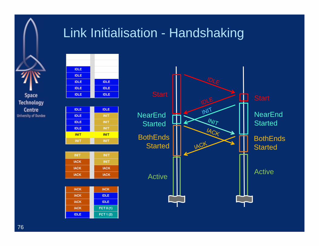
Active Active
Start
NearEndStarted
Start
NearEndStarted
BothEndsStarted
BothEndsStarted
Link Initialisation - Handshaking
Link Initialisation - Handshaking
77
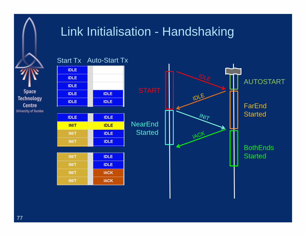
AUTOSTARTSTART
NearEndStarted
FarEndStarted
BothEndsStarted
Start Tx Auto-Start Tx
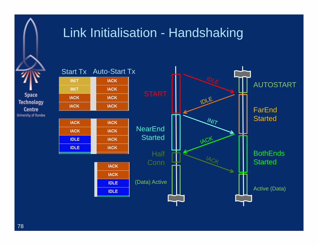
Link Initialisation - Handshaking
78
AUTOSTART
(Data) ActiveActive (Data)
START
NearEndStarted
FarEndStarted
BothEndsStarted
HalfConn
Start Tx Auto-Start Tx
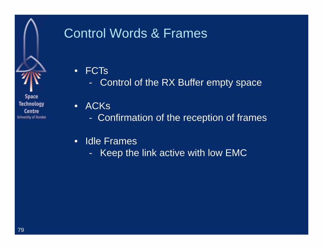
Control Words & Frames
79
• FCTs- Control of the RX Buffer empty space
• ACKs- Confirmation of the reception of frames
• Idle Frames- Keep the link active with low EMC
Control Words & Frames
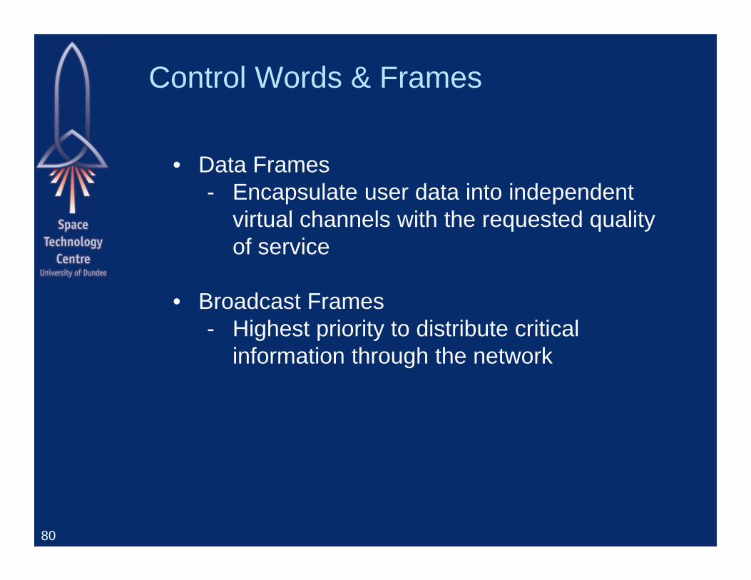
80
• Data Frames- Encapsulate user data into independent
virtual channels with the requested quality of service
• Broadcast Frames- Highest priority to distribute critical
information through the network

Quality of Service - Bandwidth Reservation
81
Virtualchannel
Sourcedata rate
BwAllocated
BwMeasured
2 45 % 50 % 45 %3 45 % 50 % 45 %
Virtualchannel
Sourcedata rate
BwAllocated
BwMeasured
2 45 % 50 % 45 %3 100 % 50 % 55 %
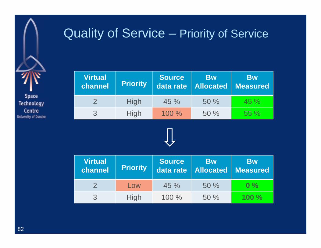
Quality of Service – Priority of Service
82
Virtualchannel Priority
Sourcedata rate
BwAllocated
BwMeasured
2 High 45 % 50 % 45 %3 High 100 % 50 % 55 %
Virtualchannel Priority
Sourcedata rate
BwAllocated
BwMeasured
2 Low 45 % 50 % 0 %3 High 100 % 50 % 100 %
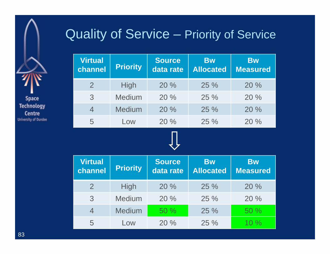
Quality of Service – Priority of Service
83
Virtualchannel Priority
Sourcedata rate
BwAllocated
BwMeasured
2 High 20 % 25 % 20 %3 Medium 20 % 25 % 20 %4 Medium 20 % 25 % 20 %5 Low 20 % 25 % 20 %
Virtualchannel Priority
Sourcedata rate
BwAllocated
BwMeasured
2 High 20 % 25 % 20 %3 Medium 20 % 25 % 20 %4 Medium 50 % 25 % 50 %5 Low 20 % 25 % 10 %
Complex configuration
84
Virtualchannel Priority
Sourcedata rate
BwAllocated
BwMeasured
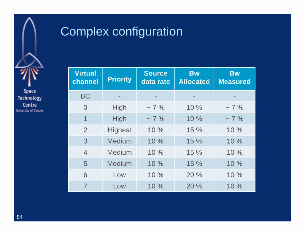
BC - - - -0 High ~ 7 % 10 % ~ 7 %1 High ~ 7 % 10 % ~ 7 %2 Highest 10 % 15 % 10 %3 Medium 10 % 15 % 10 %4 Medium 10 % 15 % 10 %5 Medium 10 % 15 % 10 %6 Low 10 % 20 % 10 %7 Low 10 % 20 % 10 %
SpaceFibre Next Steps
85
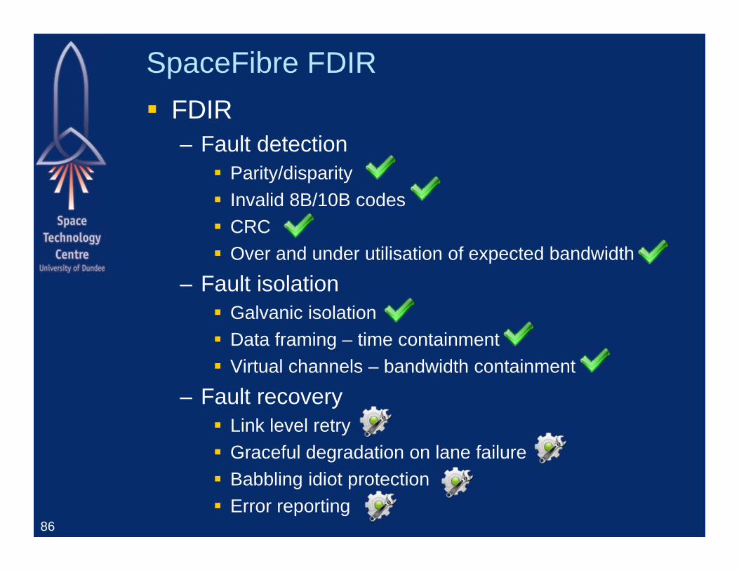
SpaceFibre FDIR FDIR
– Fault detection Parity/disparity Invalid 8B/10B codes CRC Over and under utilisation of expected bandwidth
– Fault isolation Galvanic isolation Data framing – time containment Virtual channels – bandwidth containment
– Fault recovery Link level retry Graceful degradation on lane failure Babbling idiot protection Error reporting
86
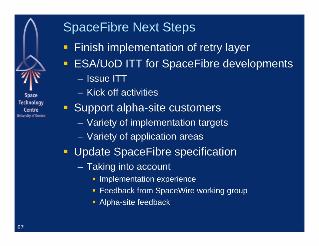
SpaceFibre Next Steps Finish implementation of retry layer ESA/UoD ITT for SpaceFibre developments
– Issue ITT– Kick off activities
Support alpha-site customers– Variety of implementation targets– Variety of application areas
Update SpaceFibre specification– Taking into account
Implementation experience Feedback from SpaceWire working group Alpha-site feedback
87
SpaceWire-RT
EU FP7 ProjectRussian and European Partners
SUAI, SubMicron, ELVEESUniversity of Dundee, Astrium GmbH
88
The SPACEWIRE-RT project has received funding from the European Union Seventh Framework Programme (FP7/2007-2013) under Grant Agreement no. 263148
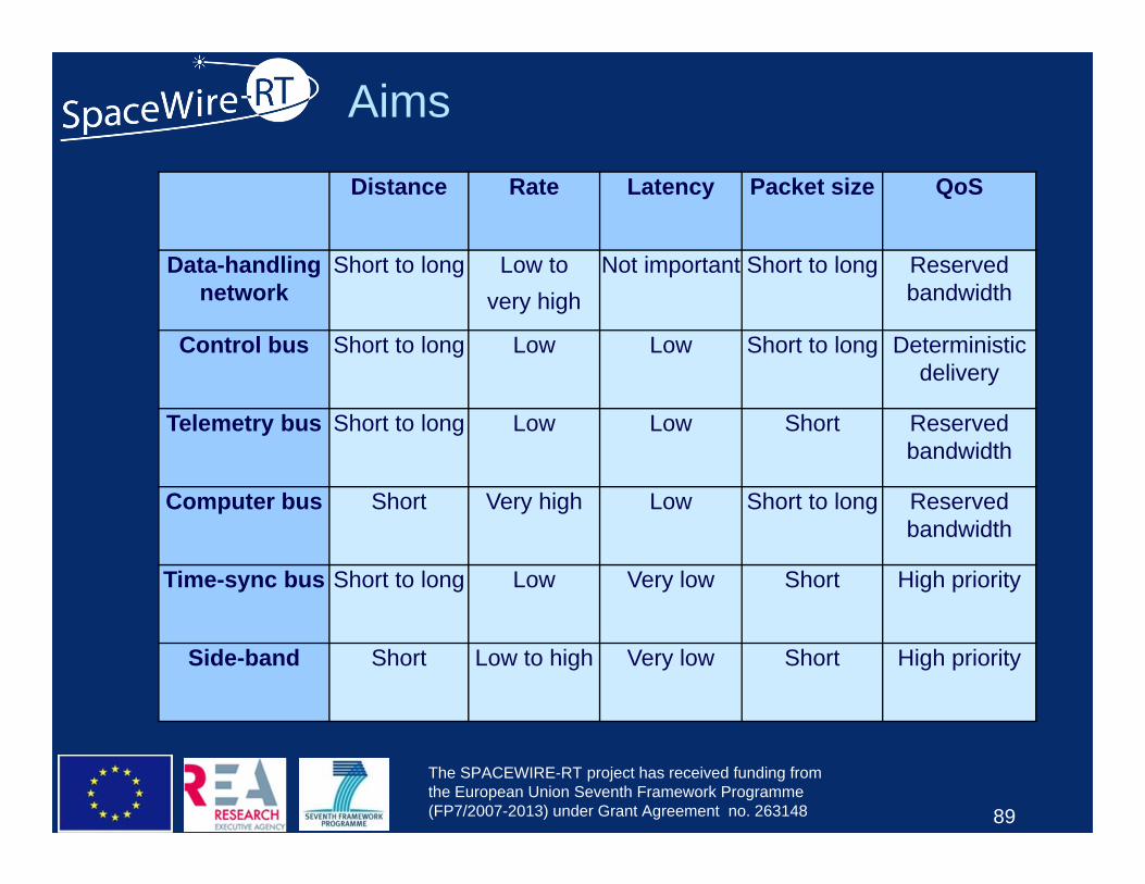
Aims
89
Distance Rate Latency Packet size QoS
Data-handling network
Short to long Low to very high
Not important Short to long Reserved bandwidth
Control bus Short to long Low Low Short to long Deterministic delivery
Telemetry bus Short to long Low Low Short Reserved bandwidth
Computer bus Short Very high Low Short to long Reserved bandwidth
Time-sync bus Short to long Low Very low Short High priority
Side-band Short Low to high Very low Short High priority
The SPACEWIRE-RT project has received funding from the European Union Seventh Framework Programme (FP7/2007-2013) under Grant Agreement no. 263148
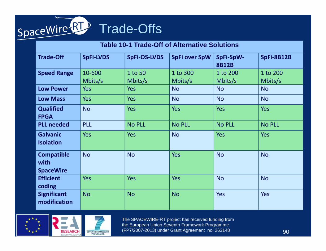
Trade-OffsTable 10-1 Trade-Off of Alternative Solutions
Trade‐Off SpFi‐LVDS SpFi‐OS‐LVDS SpFi over SpW SpFi‐SpW‐8B12B
SpFi‐8B12B
Speed Range 10‐600 Mbits/s
1 to 50 Mbits/s
1 to 300 Mbits/s
1 to 200 Mbits/s
1 to 200 Mbits/s
Low Power Yes Yes No No NoLow Mass Yes Yes No No NoQualified FPGA
No Yes Yes Yes Yes
PLL needed PLL No PLL No PLL No PLL No PLLGalvanic Isolation
Yes Yes No Yes Yes
Compatible with SpaceWire
No No Yes No No
Efficient coding
Yes Yes Yes No No
Significant modification
No No No Yes Yes
90
The SPACEWIRE-RT project has received funding from the European Union Seventh Framework Programme (FP7/2007-2013) under Grant Agreement no. 263148
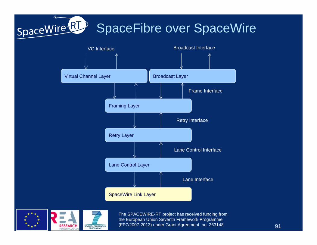
SpaceFibre over SpaceWire
91
Lane Interface
Retry Interface
Virtual Channel Layer
Retry Layer
SpaceWire Link Layer
VC Interface
Frame Interface
Framing Layer
Lane Control Interface
Lane Control Layer
Broadcast Interface
Broadcast Layer
The SPACEWIRE-RT project has received funding from the European Union Seventh Framework Programme (FP7/2007-2013) under Grant Agreement no. 263148
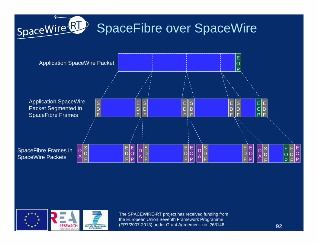
SpaceFibre over SpaceWire
92
EDF
SDF
EOP
EOP
DA
EDF
SDF
EDF
SDF
SDF
EOP
EDF
EDF
SDF
EDF
SDF
EOP
DA
EDF
SDF
EOP
DA
SDF
EOP
EDF
EOP
DA
Application SpaceWire Packet
Application SpaceWirePacket Segmented inSpaceFibre Frames
SpaceFibre Frames in SpaceWire Packets
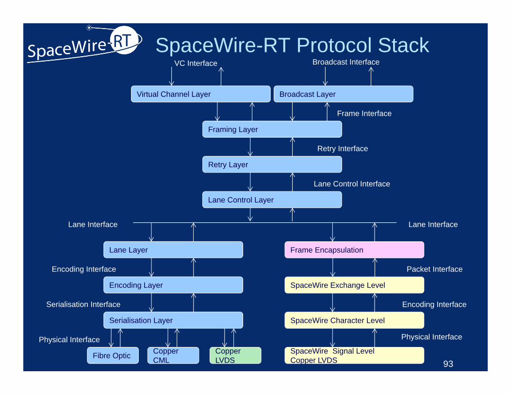
SpaceWire-RT Protocol Stack
93
Lane Interface
Retry Interface
Virtual Channel Layer
Retry Layer
Lane Layer
VC Interface
Frame Interface
Framing Layer
Lane Control Interface
Lane Control Layer
Broadcast Interface
Broadcast Layer
Encoding Interface
Encoding Layer
Serialisation Interface
Serialisation Layer
Physical InterfaceCopper CMLFibre Optic Copper
LVDS
Lane Interface
Packet Interface
SpaceWire Exchange Level
Encoding Interface
SpaceWire Character Level
SpaceWire Signal LevelCopper LVDS
Physical Interface
Frame Encapsulation
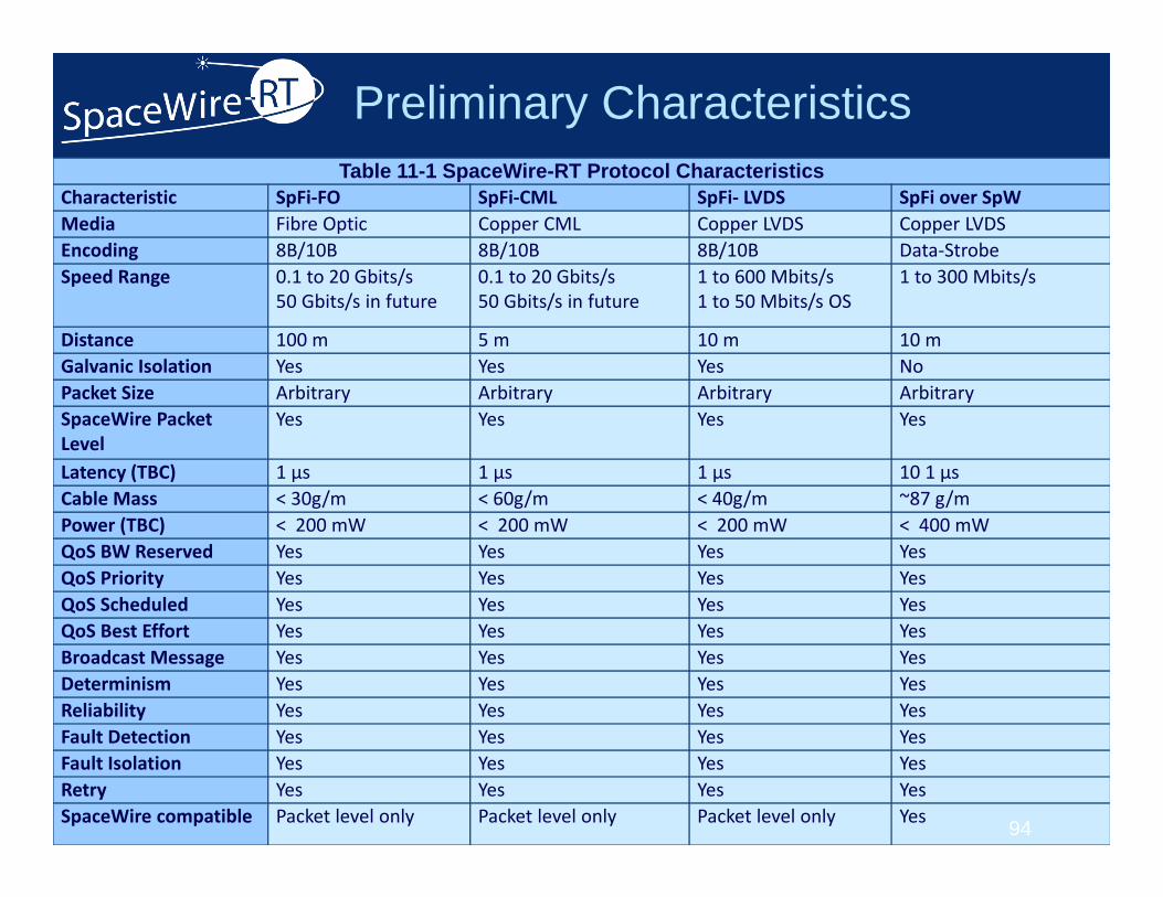
Preliminary CharacteristicsTable 11-1 SpaceWire-RT Protocol Characteristics
Characteristic SpFi‐FO SpFi‐CML SpFi‐ LVDS SpFi over SpWMedia Fibre Optic Copper CML Copper LVDS Copper LVDSEncoding 8B/10B 8B/10B 8B/10B Data‐StrobeSpeed Range 0.1 to 20 Gbits/s
50 Gbits/s in future0.1 to 20 Gbits/s50 Gbits/s in future
1 to 600 Mbits/s1 to 50 Mbits/s OS
1 to 300 Mbits/s
Distance 100 m 5 m 10 m 10 mGalvanic Isolation Yes Yes Yes NoPacket Size Arbitrary Arbitrary Arbitrary ArbitrarySpaceWire Packet Level
Yes Yes Yes Yes
Latency (TBC) 1 µs 1 µs 1 µs 10 1 µsCable Mass < 30g/m < 60g/m < 40g/m ~87 g/mPower (TBC) < 200 mW < 200 mW < 200 mW < 400 mWQoS BW Reserved Yes Yes Yes YesQoS Priority Yes Yes Yes YesQoS Scheduled Yes Yes Yes YesQoS Best Effort Yes Yes Yes YesBroadcast Message Yes Yes Yes YesDeterminism Yes Yes Yes YesReliability Yes Yes Yes YesFault Detection Yes Yes Yes YesFault Isolation Yes Yes Yes YesRetry Yes Yes Yes YesSpaceWire compatible Packet level only Packet level only Packet level only Yes 94
Summary SpaceFibre designed for spacecraft
– SpaceWire packets– Very high speed– QoS and FDIR
Specification– Initial draft under review– CODEC implemented and under test– Retry function to be added– Specification to be updated by end 2012
Radiation tolerant implementations– FPGA with external SerDes– VHiSSI ASIC– Physical layer components available
95
Summary SpaceWire-RT aims to
– Extend SpaceFibre to cover– Broad range of space applications– Including mixed data-handling and avionics
96