slot cutter products - coneqtec-universal · 2017-07-04 · 6 3. i n t r o d u c t i o n the ssg...
TRANSCRIPT

SG SERIES
SLOT CUTTER PRODUCTS
Operating and Maintenance Manual
1
TABLE OF CONTENTS 1. PRODUCT WARRANTY…………………………………………………………. 3 2. CHECKLIST Dealer’s File Copy…………………………………………………. 4 Customer’s File Copy……………………………………………….. 5 3. INTRODUCTION…………………………………………………………………… 6 4. SPECIFICATIONS………………………………………………………………….. 7 5. SAFETY……………………………………………………………………………... 8 5.1 Mandatory Safety shutdown Procedure……………………………………... 9-10 6. OPERATION………………………………………………………………………... 11 6.1 Forward……………………………………………………………………… 11 6.2 Attaching to and Detaching from a Host Machine….………………………. 11 6.2.1 Skidsteer Loader…………………………………………………… 12 6.2.2. Loader Backhoe & Compact Excavator…………………………... 12 6.3 Preparing to Cut ………..…………………………………………………… 12 6.4 Starting the Cut……………………………………………………………… 13 6.5 Advancing the Cut…………………………………………………………… 13 6.6 Ending the Cut………………………………………………………………. 13 7. DAILY MAINTENANCE………………………………………………………….. 14 7.1 Pic Removal and Replacement…………..………………………………….. 15 7.2 Removal……………………………………………………………………… 15 7.3 Replacement………………………………………………………………… 16 7.4 Changing a Wheel…………………………………………………………… 17 8. PARTS SSG Drawing & Parts List……………………………………………………….. 18-19 SSL 4-Line Hyd. Drawing & Parts List…………………………………………..... 20-21 SSL 2-Line Hyd. Drawing & Parts List……………………………………………. 22-23 Host Kits………………………………………………………………………….. 24-25 BSG Drawing & Parts List……………………………………………………….. 26-27 Danfoss Motor Drawing & Parts List……………………………………………. 28 Eaton 6K Motor Drawing & Parts List…………………………………………… 29
Revised 05/25/05

2

3
1. PRODUCT WARRANTY

4
After the Slot Cutter has been completely setup and attached to the host machine, inspect the following. Check off each item after the prescribed action is taken.
Check that: ♦ No parts of the unit have been damaged
in shipment. Check for things such as dents and loose or missing parts; correct or replace components as required.
♦ All bolts and fasteners are in place and tightly secured.
♦ All grease fittings have been properly lubricated; see lubrication information in this manual.
♦ All decals are in place and securely attached.
♦ The serial number of your unit is recorded in the space provided on this page.
♦ Then, test run the unit while checking that all components are operating correctly.
I acknowledge that the procedures were performed on this unit as outlined above —————————————————
DEALERSHIP NAME
—————————————————- DEALER REPRESENTATIVE’S NAME
————————————————
DATE CHECKLIST FILLED OUT
—————————————————
2. CHECKLIST DEALER’S FILE COPY 2.1 PRE-DELIVERY
The following checklist is an important reminder of the valuable information that MUST be passed on to the Customer at the time the unit is delivered. Check off each item as you explain it to the Customer. ♦ Give the customer his operators manual. Instruct him to be sure to read and
completely understand its contents BEFORE operating the unit.
♦ Explain and review with him the SAFETY information in this manual.
♦ Explain that regular cleaning and lubrication are required for proper operation and long life. Review with him the lubrication information in this manual.
♦ Explain and review with him the service & maintenance information in this manual.
♦ Completely fill out the owner’s registra-tion, including the customer’s signature and return it to the manufacturer.
I acknowledge that the above points were reviewed with me at the time of delivery. ———————————————————
CUSTOMER’S SIGNATURE
——————————————————— DATE DELIVERED
2.2 DELIVERY

5
After the Slot Cutter has been completely setup and attached to the host machine, inspect the following. Check off each item after the prescribed action is taken.
Check that: ♦ No parts of the unit have been damaged
in shipment. Check for things such as dents and loose or missing parts; correct or replace components as required.
♦ All bolts and fasteners are in place and tightly secured.
♦ All grease fittings have been properly lubricated; see lubrication information in this manual.
♦ All decals are in place and securely attached.
♦ The serial number of your unit is recorded in the space provided on this page.
♦ Then, test run the unit while checking that all components are operating correctly.
I acknowledge that the procedures were performed on this unit as outlined above —————————————————
DEALERSHIP NAME
—————————————————- DEALER REPRESENTATIVE’S NAME
————————————————
DATE CHECKLIST FILLED OUT
————————————————— SERIAL NUMBER
2. CHECKLIST CUSTOMER’S FILE COPY 2.1 PRE-DELIVERY
The following checklist is an important reminder of the valuable information that MUST be passed on to the Customer at the time the unit is delivered. Check off each item as you explain it to the Customer. ♦ Give the customer his operators manual. Instruct him to be sure to read and
completely understand its contents BEFORE operating the unit.
♦ Explain and review with him the SAFETY information in this manual.
♦ Explain that regular cleaning and lubrication are required for proper operation and long life. Review with him the lubrication information in this manual.
♦ Explain and review with him the service & maintenance information in this manual.
♦ Completely fill out the owner’s registration, including the customer’s signature and return it to the manufacturer.
I acknowledge that the above points were reviewed with me at the time of delivery. ———————————————————
CUSTOMER’S SIGNATURE
——————————————————— DATE DELIVERED
2.2 DELIVERY

6
3. I N T R O D U C T I O N
The SSG & BSG SERIES SLOT CUTTER was designed as an attachment machine for use on host machines such as skid steer loaders, loader backhoes, and compact excavators. The information contained in this manual refers only to the Slot Cutter Machine. Information regarding the valve used to control oil flow to the Slot Cutter attachment can be found in the host machine’s manual or the power pack installation manual if the host machine is so equipped. The information contained within is provided to assist you in preparing, adjusting, maintaining and servicing your machine. More importantly, this manual provides an operating plan for safe and proper use of your machine. Major points of safe operation are detailed in the safety chapter of this manual. Refer to the table of contents for an outline of this manual. Modern machinery has become more sophisticated and, with that in mind, you must read and understand the contents of the manual COMPLETELY and become familiar with your new machine before attempting to operate it. Terms such as “right” and “left” as used in the manual, are as though the reader is sitting in the host machine’s operator seat and facing the slot cutter. Throughout this manual, information is provided which is set in bold type and introduced by the word NOTE: Be sure to read carefully and comply with the message or directive given. Following this information will improve your operating or maintenance efficiency, help you to avoid costly breakdowns or unnecessary damage, and extend the life of your machine. The Manufacturer and Society of Automotive Engineers have adopted this SAFETY ALERT SYMBOL to pinpoint characteristics that, if not properly followed, can create a safety hazard. When you see this symbol in this manual or on the unit itself, you are reminded to BE ALERT! YOUR SAFETY IS INVOLVED!
The manufacturer reserves the right to make changes or improvements in the design or construction of any part without the obligation to install such changes on any unit previously delivered.

7
4. S P E C I F I C A T I O N S
AP300...................................................................................................12 INCHES (300mm)
SG SERIES
MAXIMUM CUTTING DEPTH 7 inches (178 mm) OPTIONAL SIDE-SHIFT TRAVEL (SSG-7 only) 24 inches (610 mm) WEIGHT* SG-7 (base head unit) 500 lbs. (227 kg) CROSSLIDE PLATE (S.S. loader hitch) 400 lbs. (182 kg) MOUNTING CRADLE (loader backhoe, or excavator) 85 lbs. (39 kg) * Weights are for hydraulic slot cutters equipped for use on skidsteer loaders, backhoe loaders, and compact excavators, and are approximate due to optional equipment.
MODEL STANDARD CUTTING WIDTH
SSG-7…………………………………………………………….3 INCHES (76 mm) SSG-7 (Optional)………………………………………………. .5 INCHES (127 mm) SSG-9 ……………………………………………………………3 INCHES (76 mm) SSG-9 (Optional) ………………………………………………..5 INCHES (127 mm) BSG-7……………………………………………………………3 INCHES (76 mm) BSG-7 (Optional)………………………………………………...5 INCHES (127 mm) BSG-9 ……………………………………………………………3 INCHES (76mm) BSG-9 (Optional) ………………………………………………..3 INCHES (127 mm)

8
BEFORE YOU ATTEMPT TO OPERATE THIS EQUIPMENT, READ AND STUDY THE FOLLOWING SAFETY INFORMATION. IN ADDITION, MAKE SURE THAT EVERY IN-DIVIDUAL WHO OPERATES OR WORKS WITH THIS EQUIPMENT IS FAMILIAR WITH THESE SAFETY PRECAUTIONS. The Manufacturer always takes the operator and their safety into consideration when designing machinery. Guards are provided on exposed moving parts for the operator’s protection, however, some areas cannot be guarded or shielded in order to assure proper operation. In addition, the operator’s manual and decals on the machine itself warn you of further danger and should be read and observed closely. The SAFETY ALERT SYMBOL above means ATTENTION! BECOME ALERT! YOUR SAFETY IS INVOLVED! It stresses an attitude of “HEADS UP” for safety and can be found throughout this operator’s manual and on the unit itself. REMEMBER: The careful operator is the best operator. Most accidents are caused by human error. Certain precautions must be observed to prevent the possibility of injury or damage. Please read the rules listed below for safe operation BEFORE you operate this equipment. Use of the words CAUTION, WARNING, or DANGER herein and on the machine itself signal three degrees of hazard: CAUTION is used for general reminders of good safety practices or to direct attention to unsafe practices. WARNING is used to denote a specific potential hazard. DANGER is used to denote the most serious specific potential hazard.
5. SAFETY

9
5.1 MANDATORY SAFETY SHUTDOWN PROCEDURE Work of any type on machinery is always more dangerous when the machine is operating. BEFORE cleaning, lubricating, or servicing this unit, the following MANDATORY SAFETY SHUTDOWN PROCEDURE should ALWAYS be followed: 1 Move host machine’s propulsion control to the neutral position and idle engine down. 2. Shut off Slot Cutter.
3. Position Cutter so that it is completely resting on the ground or floor.
4. Engage the host machine’s hand brake, or parking brake. 5. With the host machine’s throttle to the slow idle position, shut the Engine off and remove the Ignition Key. 6. Relieve hydraulic pressure by moving the Hi-flow and cylinder control levers in both directions
REMEMBER ALWAYS IDLE ENGINE DOWN BEFORE SHUTTING OFF OIL FLOW.
ONLY when you have taken these precautions can you be sure it is safe to proceed. Failure to follow the above procedures could lead to death or serious bodily injury! Some diagrams used herein may show Door(s), Guard(s), or Shield(s) open or removed for illustration purposes ONLY! BE SURE that all Door(s), Guard(s), and Shield(s) are in their proper position(s) and securely attached BEFORE operating the Cutter! Read and observe ALL Safety information and decals on the host machine and Cutter BEFORE operating the unit! In addition, familiarize yourself with ALL of the safety devices and periodically check that they are functioning properly! Refer to the SAFETY chapter of the host machine’s operator manual and observe ALL Safety recommendations set forth in that manual! CAREFULLY inspect ALL hydraulic hoses and connections on a routine basis; NEVER use your hand, escaping fluid under pressure can cause serious injury!

10
BE SURE to exercise the MANDATORY SAFETY SHUT DOWN PROCEDURE BEFORE proceeding to do any work on the Cutter! BE SURE the Cutter is properly placed in the “service position” and resting on the ground BE-FORE attempting to work on the machine. BEFORE transporting the Cutter, BE SURE to raise the unit completely clear of the ground and turn it off. When replacing pics, BE SURE to use only a soft or lead headed hammer when inserting the pics into the holders. ALWAYS wear safety glasses with side shields when striking metal against metal! In addition, it is recommended that a softer (non-chippable) material be used to cushion the blow. Failure to heed could result in serious injury to the eye (s) or other part (s) of the body! ALWAYS wear proper clothing and covering when working with or on the Cutter. DO NOT attempt to move the cutter sideways while it is on the ground! DO NOT attempt to work on the cutter or host machine with the hydraulics live! BE SURE to re-lieve the hydraulic pressure by shutting down the engine and moving all control levers BEFORE attempting to disconnect any hoses or BEFORE proceeding to remove the cutter from the host machine. DO NOT treat the cutter like a bucket. It can be damaged by contact with solid objects as well as upset the stability of the host machine! DO NOT hit the pics with a steel hammer as this could cause steel chips to fly, causing injury to the eyes or face. REMEMBER! It is the owner’s responsibility to communicate information regarding the safe use and proper operation and maintenance to any user of this machine!

11
6. O P E R A T I O N 6.1 FOREWORD The Cutter must be attached to a host machine equipped to provide the necessary hydraulics and operational controls. As there are many different host machines available, this manual will only deal with the generic operation of the Cutter. Anyone attempting to attach and operate the Cutter must first have the knowledge and skill of operating the host machine’s controls. Information regarding the host machine’s controls and attaching procedure is found in the host machine’s Operators Manual or from its Authorized Dealer.
6.2 ATTACHING TO AND DETACHING FROM A HOST MACHINE Drive the skidsteer up to the quick attach of the slot cutter and connect up. Exercise the MANDATORY SAFETY SHUTDOWN PROCEDURE before proceeding. After installing hydraulic quick couplers compatible with your skidsteer to the hydraulic hoses of the slot cutter, connect them to the hydraulic outlet as follows: 1. If your skidsteer has five lines i.e. (2 high flow , 2 auxiliary, and 1 case drain): The 3/4” hose attached to the # “2” port of the overrunning valve must be connected to the pressure outlet of the skidsteer’s high flow. The 3/4” hose attached to the # “1” port must be connected to the return outlet. The two 1/4” hoses must be connected to the skidsteer’s auxiliary outlets. The 3/8” case drain line must be connected to the skidsteer’s case drain outlet. 2. If your skidsteer has 3 lines i.e. (2 high flow lines, and 1 case drain): The 3/4” hose attached to the “C” port of the selector valve must be connected to the pressure outlet of the skidsteer, and the 3/4” hose attached to the “D” port of the selector valve to the re- turn outlet. The 3/8” case drain line must be attached to the skidsteer’s case drain outlet. 3. On slot cutters on standard flow skidsteer’s without a case drain, connect as per “2” but omit the case drain connection.

12
6.2.1 SKIDSTEER LOADER Drive the skidsteer up to the quick attach of the Cutter and connect up. Exercise the MANDATORY SAFETY SHUTDOWN PROCEDURE before proceeding. After installing hydraulic quick couplers compatible with those on the skid steer to the two main motor hoses, connect them to the hydraulic outlets, assuring that the hose connected to the #2 or “C” port of the valve goes to the pressure outlet. 6.2.2 LOADER BACKHOE & COMPACT EXCAVATOR After checking to make sure your slot cutter has the proper coupler assembly, position the backhoe/excavator to pick up the cutter with the quick coupler, if the unit is so equipped, or to pin to the boom. Exercise the MANDATORY SAFETY SHUTDOWN PROCEDURE before proceeding. After installing the hydraulic quick couplers and hoses compatible with your loader backhoe/excavator hydraulic couplers, connect them to the hydraulic outlets, assuring that the hose connected to the #2 port of the motor goes to the pressure outlet of the host machine. The BSG-7 cutter is intended for use on loader backhoe’s and small to medium sized excavators up to 30,000 gvw (13.608 kg), and auxiliary hydraulic flows from 16 through 26 gpm (60.6-98.4 1/m). It is recommended that the Coneqtec auxiliary hydraulic wet kit be used on your loader backhoe and adjust the hydraulic flow to the motor’s recommended flow.
6.3 PREPARING TO CUT Determine the required depth of cut and left to right position of the cutter in regards to the host machine. When it is safe to do so, start the host machine’s engine, and ensure that the cutter wheel is not touching the ground. Turn on the cutter, and check the cutter rotation. The teeth at the bottom of the wheel must be moving in the same direction that the cutter travels over the material to be cut. If the wheel rotates incorrectly, correct the cutter installation before attempting to cut. In skidsteer operation, only forward travel should be used. In backhoe/excavator operation, only pulling cutter to host machine direction should be used. Increase engine rpm, with the wheel turning. You can now make necessary adjustments to the left and right position of the cutter. A hydraulic cylinder holds the cutter in position on the mounting plate slide. Actuate the cylinder to adjust the desired left/right position. Note: Backhoe installations do not include a left/right slide function.

13
6.4 STARTING THE CUT Position the cutter over the desired starting place. With the cutter turned on, the depth shoe at “0” or resting on the starting area and the host machine’s engine at full rpm, slowly rotate the cutter into the surface to be cut. Continue to increase cutting depth by rolling the dump forward cylinder (on a skidsteer or front end loader), or by rolling up the bucket cylinder (on backhoe/excavator). For example, the front wheels of the skidsteer may be raised 2-3 inches (50-75 mm) off the cutting surface. Maximum depth of each cut is determined by the type of material being cut, the weight and hydraulic horsepower of the host machine, and the width of cutter being used.
6.5 ADVANCING THE CUT Advance the cutter in the direction the wheel pics are traveling in the cut. If the cutter wheel stalls, you have been feeding the cutter into the cut too fast or cutting too deep. Back out of the cut until the wheel restarts, and then advance again. If the cutter tends to ride up out of the cut, use the procedure outlined in the above to keep the cutter skid on the surface to be cut. DO NOT side shift the cutter while the wheel is in the cut. The wheel will not cut in a side to side direction. Depth controls may be actuated while the wheel is in the cut.
6.6 ENDING THE CUT Stop advancing the cutter and raise wheel out of the cut. If you do not wish to start a new cut, idle host machine engine, and turn the cutter off. DO NOT transport the cutter while it is running.
CAUTION: When using slot cutters, periodic observa-tion must be made of the hydraulic oil temperature indicator on the host machine. Hydraulic oil may over-heat, depending on ambient temperature and duty cycle of the machine. If indicator comes on, shut off slot cutter, and allow skidsteer loader to idle until the hy-draulic temperature falls below 180°F (82°C). Damage to machine may occur if these instructions are not followed.

14
7. DAILY MAINTENANCE NOTE: Careful attention to the daily maintenance routines will go a long way toward ensuring efficient operation. 1. At the start of each day, lubricate the bearing grease fittings at the end of the axle shaft on the right hand side of the cutter housing. Standard shop gun grease will suffice. 2. Check crosslide rods (only on S.S. hitch) for lubrication. Clean away any dust or dirt, and apply
oil to these areas. 3. Using the correct size wrenches, retighten any loose hardware. BE SURE to check motor and
bearing mounting bolts regularly. 4. Inspect for any loose hydraulic fittings of damaged hoses; retighten or replace as required. 5. At least twice a day, check all pics for freedom of rotation and wear. Replace all pics that are not rotating freely or are badly worn. Follow the procedure outlined under pic removal and replacement.
CAUTION: NEVER attempt to do any maintenance to the Cut-ter while it is running. Exercise the MANDATORY SAFETY SHUTDOWN PROCEDURE BEFORE proceeding.
WARNING: NEVER use your hands to check for hydraulic leaks. Escaping fluid under pressure can cause serious injury! If injured by escaping fluid, see a doctor at once. If proper Medical treatment is NOT administered IMMEDIATELY Serious infection or reaction can develop!

15
7.1 PIC REMOVAL AND REPLACEMENT To achieve maximum pic life and optimum performance, the pics will require replacement for the following reasons: 1. They are broken or worn. 2. They are seized in the pic holder and do not rotate freely.
7.2 REMOVAL WARNING: ALWAYS wear safety glasses with side shields when striking metal. Failure to heed could result in serious injury to the eyes or other parts of the body! To remove pic (s): 1. Rotate the wheel until the pic to be removed is conveniently accessible. 2. Hold the pic removal tool in one hand and place the jaws in the groove of the pic with the offset handle pointing away from the pic holder. 3. Using a lead hammer or rubber-headed mallet, hit the raised pad on the tool until the pic starts to move, and continue to tap it out. NOTE: If the pic does not have a groove, use a pic punch and a lead hammer or rubber-headed mallet to drive the pic out of the holder from the backside.
Exercise the MANDATORY SAFETY SHUT-DOWN PROCEDURE but find an elevated sur-face to set the cutter on, or have a second person block the cutter in place before shutting off the host machine.

16
7.3 REPLACEMENT To replace a pic proceed as follows: 1. With the pic removal tool in one hand, position the new pic in the jaws of the tool so that the raised pad of the tool is pointing in the same direction as the pic point. 2. Position the stem of the pic in the hole of the pic holder. 3. With a lead hammer or rubber-headed mallet, hit the raised pad of the tool to start the pic into the holder. 4. With one strong blow, strike the tool pad to pop the pic into the hole of the holder. The pic is properly seated when it’s shoulder is against the face of the pic holder. BE SURE to test that the pic rotates freely. NOTE: If the pic does not have a groove, position the stem of the pic in the hold in the holder, and using a lead hammer or rubber-headed mallet, lightly hammer the point of the pic until the pic is seated in the holder.
WARNING: ALWAYS wear safety glasses with side shields when striking metal. Failure to heed could result in serious injury to the eyes or other parts of the body!

17
7.4 CHANGING A WHEEL 1. Place the cutter in a convenient position. 2. Remove the four socket head cutter motor bolts, and pull the motor out of the wheel. Some mo-
tors are difficult to remove and may require a pulling device. 3. After the motor has been removed, remove the four bolts from the axle shaft bearing, and pull
the axle shaft and wheel straight out of the slot. 4. Check all hardware removed, and replace if damaged. 5. Reverse instructions 1 and 2 to complete the wheel change. Upon installing the motor, clean the shaft bore and motor shaft, and coat with an anti-seize.

18
19
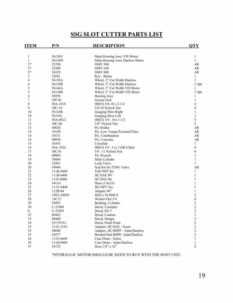
SSG SLOT CUTTER PARTS LIST
ITEM P/N DESCRIPTION QTY 1 56136V Main Housing Assy VIS Motor 1 1 56136D Main Housing Assy Danfoss Motor 1 2* 52708 OMV 500 AR 2* 52588 OMV 630 AR 2* 54329 OMV 800 AR 3 52681 Key - Motor 1 4 56158A Wheel, 3” Cut Width Danfoss 1 4 56158B Wheel, 5” Cut Width Danfoss 1 Opt 5 56144A Wheel, 3” Cut Width VIS Motor 1 5 56144B Wheel, 5” Cut Width VIS Motor 1 Opt 6 54958 Bearing Assy 1 7 29F-01 Grease Zerk 1 8 50A-1018 HHCS 5/8-18 x 2-1/4 4 9 30C-10 5/8-18 Nylock Nut 4 10 56143R Gauging Shoe Right 1 10 56143L Gauging Shoe Left 1 11 50A-0612 HHCS 3/8 –16x 1-1/2 5 12 30C-06 3/8” Nylock Nut 5 13 40028 Pic Holder AR 14 10150 Pic, Low Torque Pyramid Flare AR 14 10151 Pic, Combination AR 14 40030 Pic, Concrete AR 15 54343 Crosslide 1 16 50A-1024 HHCS 5/8 –11x 3 GR 8 Bolt 4 17 30C10 5/8 –11 Nylock Nut 4 18 40069 Pic Wrench 1 19 54064 Slide Cylinder 1 20 52981 Lock Valve 1 20 54946 Seal Kit for 52981 Valve AR 21 111K-0604 SAE/NPT Str 1 22 111B-0406 JIC/SAE 90° 1 23 111E-0406 JIC/SAE Str 1 24 54114 Hose (1/4x25) 1 25 111Y-0404 JIC/NPT Tee 1 26 112B-04 Adapter 90° 1 27 350A-20050 M20 x 50 HHCS 2 28 14C12 Washer Flat 3/4 4 29 54991 Bushing, Cylinder 2 30 C-21088 Decal, Coneqtec 2 31 C-21093 Decal, SG-7 2 32 80443 Decal, Caution 1 33 80440 Decal, Danger 2 34 251747A1 Decal, Pinch Point 2 35 111E-1216 Adapter, JIC/SAE - Eaton 2 35 40040 Adapter, JIC/BSPP - Adan/Danfoss 2 35 42077 Bonded Seal BSPP- Adan/Danfoss 2 36 111E-0604 Case Drain - Eaton 1 36 111Q-0604 Case Drain - Adan/Danfoss 1 37 54723 Hose 3/4” x 52” 2
*HYDRAULIC MOTOR SHOULD BE SIZED TO RUN WITH THE HOST UNIT.
20

21
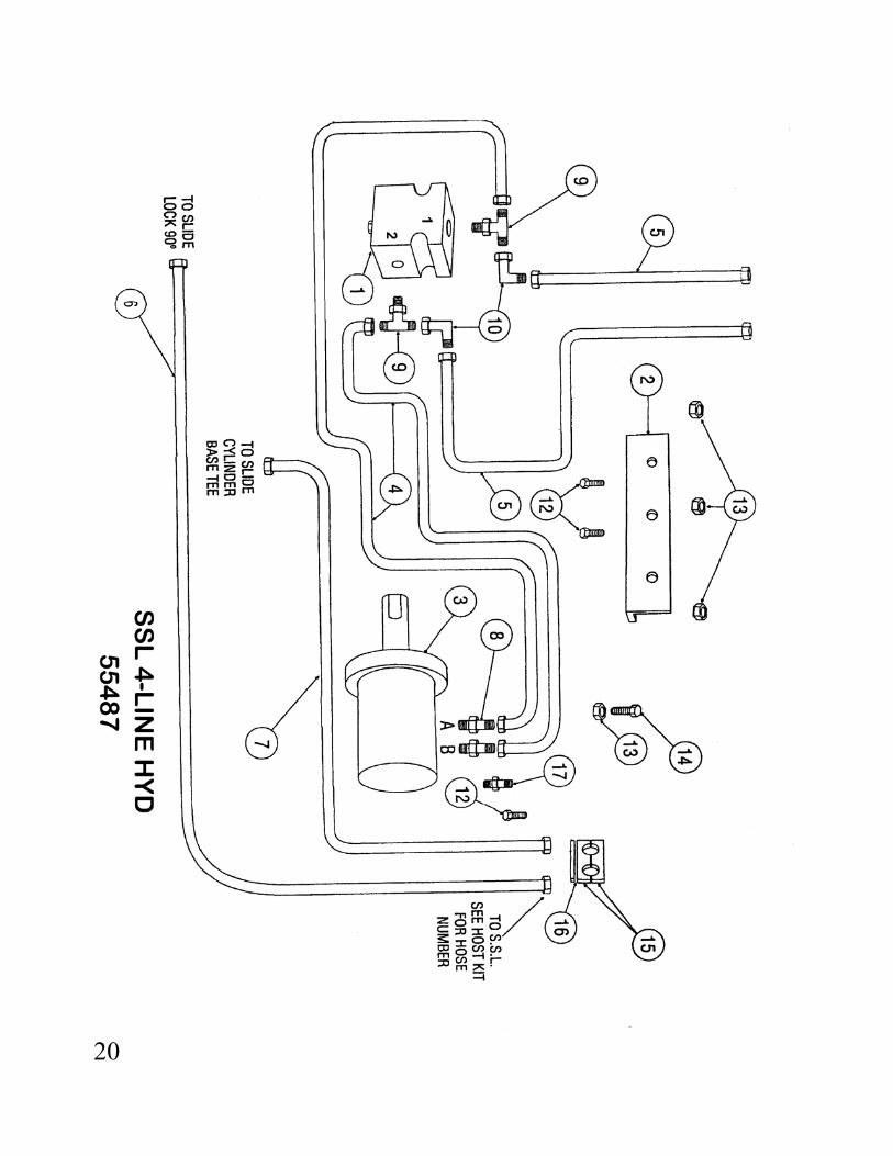
4-LINE HYD PARTS LIST
55487
ITEM P/N DESCRIPTION QTY 1 55344 Overruning Valve 1 1 56049 Seal Kit for O.R. Valve AR 2 55463 O.R. Valve Bracket 1 3 Motor - (See Motor Size Table) 1 4 54723 Hose 3/4” x 52” Motor Pressure 2 5* Hose 3/4” To S.S.L. 2* 6* Hose 1/4” Slide Cylinder 1* 7* Hose 1/4” Slide Cylinder 1* 8 40040 Adapater Motor - Adan/Danfoss SAEM / BSPP 2 8A 42077 Bonded Seal - Adan/Danfoss 2 8 111E-1216 Adapter Motor - Eaton JICM / SAEM 2 9 111C-12 Adapter Tee JICM / SAEM 2 10 112B-12 Adapter 90° HHCF / JICM 2 11 50A-0516 5/16-18 x 2 HHCS 1 12 50A-0522 5/16-18 x 2-3/4 HHCS 2 13 30C-05 5/16-18 Nylock Nut 4 14 50A-0510 5/16-18 x 1-1/4 HHCS 2 15 54047 Hose Clamp 1/4 (Pair) 1 16 54048 Hose Clamp Plate 1 17 111E-0604 Adapter Case Drain Eaton 1 17 111Q-0604 Adapter Case Drain Adan/Danfoss 1
* HOSES WILL DEPEND ON WHICH S.S.L. THE PLANER IS ON. SEE HOST KIT FOR THAT LOADER.

22

23
2-LINE HYD PARTS LIST 55488
ITEM P/N DESCRIPTION QTY 1 55472 Selector Valve Inc Lever 1 1 56050 Seal Kit Selector Valve AR 2 55483 Lever only 1 2 55621 Lever Link Kit AR 2 55622 Lever Link Bkt AR 3 55344 Overrunning Valve 1 3 56049 Seal Kit for O.R. Valve AR 4 55481 O.R. Valve Bracket 1 5 55480 Selector Valve Bracket 1 6 54026 Hose 1/4 x 15” 1 7 55482 Hose 1/4 x 35” 1 8 54723 Hose 3/4 x 52” Motor Pressure / Return 2 9 110G-1216 Adapter Str JICM / NPTM 2 10 115B-1608 Adapter Reducer NPTF / NPTM 2 11 110R-0408 Adapter 90° JICM / NPTM 2 12 115B-1612 Adapter Reducer NPTF / NPTM 1 13 110AH-1212 Adapter Tee JICM / NPTM 1 14 111V-12 Adapter Str SAEM / NPTF 1 15 111B-1212 Adapter 90° JICM / SAEM 1 16 110Y-1216 Adapter Tee JICM / NPTM 1 17 112B-12 Adapter 90° JICM / JICF 1 18 55479 Tube Assy 3/4” x 180° 1 19 50A-0522 5/16-18 x 2-3/4 HHCS 4 20 50A-0510 5/16-18 x 1-1/4 HHCS 4 21 30C-05 5/16-18 Nylock Nut 8 22 14C-05 5/16 Flatwasher 2 23* Hose 3/4” TO SSL 2
* HOSES WILL DEPEND ON WHICH S.S.L. PLANER IS ON. SEE HOST KIT FOR THAT LOADER.
* WATER KIT –WG55/SSG77 SPRAY BAR KIT ONLY 56148

24
HOST KITS
55465X BOBCAT HI FLO HOST KIT
Part # Description Qty
55900 3/4 x 72” Hose 2 55174 1/4 x 105” Hose 1 55476 1/4 x 125” Hose 1 54136 3/8 x 106” Case Drain Hose 1 111E-0608 Case Drain QC Adapter 1 111E-1212 Adapter 2 111E-0408 Adapter 2 55466X CASE-GEHL-MUSTANG-TRAK-THOMAS WITH UNIVERSAL Q.A. & HI FLO HOST KIT Part # Description Qty 55524 3/4 x 100” Hose 2 55477 1/4 x 62” Hose 1 55478 1/4 x 80” Hose 1 54822 3/8 x 157” Case Drain Hose 1 111E-1212 Adapter 2 111E-0408 Adapter 2 111E-0610 (Case) 1 111E-0608 (Gehl, Mustang) 1 11OG-0608 (Thomas) 1 55469XH JCB HI FLO HOST KIT Part # Description Qty 55524 3/4 x 100” Hose 2 55475 1/4 x 105” Hose 1 55476 1/4 x 125” Hose 1 54822 3/8 x 157” Case Drain Hose 1 40040 Adapter 2
111Q-0406 Adapter 2 111Q-0608 Case Drain QC Adapter 1

25
HOST KITS (Cont.) 55470 NEW HOLLAND-JOHN DEERE, HOST KIT Part # Description Qty 55900 3/4 x 72” Hose 2 54822 3/8 x 157” Case Drain Hose 1 111E-1212 Adapter 2 111E-0608 Case Drain QC Adapter 1
55665X CAT 248 HOST KIT-APX & SSG7 Part # Description Qty 55902 3/4 x 72" Hose 2 55486 1/4 x 90" Hose 1 55174 1/4 x 106" Hose 1 54170 3/8 x 125" Case Drain Hose 1 111E-1212 Adapter 2 111E-0608 Adapter 1
111E-0408 Adapter 2
55704X CASE APX & SSG 5000 PSI Part # Description Qty 55538 3/4 X 100" Hose 2 55486 1/4 x 90" Hose 1 55174 1/4 x 106" Hose 1 54822 3/8 x 157 Case Drain Hose 1 111E-1212 Adapter 2 111E-0610 Adapter 1 111E-0410 Adapter 2

26

27
BSG SLOT CUTTER PARTS LIST
ITEM P/N DESCRIPTION QTY 1 C-21001 Main Housing Assy 1 2* 52708 OMV 500 AR 2* 52588 OMV 630 AR 2* 54329 OMV 800 AR 3 52681 Key-Motor 1 4 C-21015 Wheel, 3” Cut Width 1 5 C-21096 Wheel, 5” Cut Width OPT 6 54958 Bearing Assy 1 7 29F-01 Grease Zerk 1 8 50A-1018 HHCS 5/8-18 x 2-1/4 4 9 30C-10 5/8-18 Nylock Nut 4 10 C-21003 Gauging Shoe 1 11 50A-0612 HHCS 3/8 –16x 1-1/2 5 12 30C-06 3/8” Nylock Nut 5 13 40028 Pic Holder AR 14 10150 Pic, Low Torque Pyramid Flare AR 14 10151 Pic, Combination AR 14 40030 Pic, Concrete AR 15 C-21020 Coupler Assy for B.H. 1 15 C-21097 Coupler Assy for Mini Excavator 1 16 50A-1024 HHCS 5/8 –11x 3 GR 8 4 17 30C10 5/8-11 Nylock Nut 4 18 C-21097 Pin 1-1/2 x 10 1 19 C-21098 Pin 1-3/4 x 14-3/4 1 20 C-21099 Click Pin 2 21 55344 Overrunning Valve 1 21 56049 Seal Kit O.R. Valve AR 22 50A-0522 HHCS 5/16-18 x 2-3/4 2 23 30C-05 5/16-18 Nylock Nut 2 24 111B-1212 Adapter 90° JIC/SAE 1 25 111C-1212 Tee JIC/SAE 1 26 111C-1212 Tee JIC/SAE 1 27 C-21100 Hose (24”) 2 28 111E-0604 Case Drain - Eaton 1 28 111Q-0604 Case Drain - Adan/Danfoss 1 29 111E-1216 Adapter JIC/SAE - Eaton 2 29 40040 Bonded Seal BSPP - Adan/Danfoss 2 30 C21088 Decal, Coneqtec 2 31 C21093 Decal, BSG-7 2 32 80443 Decal, Caution 1 33 80440 Decal, Danger 2 35 40069 Pic Wrench 1 36 C-21083 35mm Pin (REF: C-21097) 2 36 C-21084 40mm Pin (REF: C-21097) 2 36 C-21085 45mm Pin (REF: C-21097) 2

28
DANFOSS MOTOR OMV PARTS LIST
ITEM P/N DESCRIPTION QTY ITEM P/N DESCRIPTION QTY 1 52676 Screw M8x1x20mm 6 26 52694 Channel Plate 1 2 52677 Dust Deal Ring 1 28 52695 Disc Valve 1 3 52678 Front Cover 1 29 52969 Balance Plate 1 4 52679 Shaft Seal 1 30 52697 Guide Pin 1 5 52680 O Ring 1 31 52698 O Ring 1 6 52681 Parallel Key 1 32 52699 O Ring 1 7 52682 Shaft Including Bearing 1 33 52700 Spacer 1 8 52683 Conical Seal Ring 1 34 52701 Spring Washer 1 9 52684 Bearing Housing 1 36 52702 Valve Housing 1 10 52685 Drain Plug Including O Ring 1 37 52703 Ball 2 13 52687 Cardan Shaft for 52708 500 mtr 1 38 52704 Springs 2 13 55333 Cardan Shaft for 52588 630 mtr 1 39 52705 Washers 2 13 55334 Cardan Shaft for 54329 800 mtr 1 40 52706 Plugs 2 22 52689 O Ring 1 41 52707 Cap Screw OMV500 & 630 4 23 52690 Gearwheel set for 52588 630mtr 1 41 55335 Cap Screw for 54329 800mtr 4 23 52691 Gearwheel set for 52708 500mtr 1 42 55254 Name Plate OMV 1 23 55332 Gearwheel set for 54329 800mtr 1 43 54930 Drive Screw 4 24 52692 Guide Pin 1 44 52829 Seal Kit OMV Includes items 1 25 52693 Valve Drive 1 2,4,5,8,22,31,32

29
EATON 6K MOTOR PARTS LIST
ITEM P/N DESCRIPTION QTY ITEM P/N DESCRIPTION QTY 1 55560 50MM Shaft & Bearing 1 15 55581 Seal 1 2 55561 Housing Bearing 1 16 55582 Seal 2 3 55562 Retainer Front 1 17 55583 Seal 2 4 50A-0508 Screw Cap 6 18 55584 Seal Dust 1 5 55563 Drive Main 390 1 19 55585 Seal Shaft 1 5 55564 Drive Main 490 1 20 55586 Seal Shaft Face 1 5 55565 Drive Main 625 1 21 55587 Screw Cap 390 2 5 55566 Drive Main 800 1 21 55588 Screw Cap 490 2 5 55567 Drive Main 985 1 21 55589 Screw Cap 625 2 6 55568 Geroler 390 1 21 55590 Screw Cap 800 2 6 55569 Geroler 490 1 21 55591 Screw Cap 985 2 6 55570 Geroler 625 1 22 55592 Screw Cap 390 2 6 55571 Geroler 800 1 22 55593 Screw Cap 490 2 6 55572 Geroler 985 1 22 55594 Screw Cap 625 2 7 55573 Plate Valve 1 22 55595 Screw Cap 800 2 8 55574 Drive Valve 1 22 55596 Screw Cap 985 2 9 55575 Valve 1 23 55599 Plug Assy 1 10 55576 Seal Face Outer 1 24 55600 Check Plug Assy 2 11 55577 Seal Face Inner 1 25 52681 Key 1 12 55578 Spring 3 26 55597 Seal 1 13 55579 Balance Ring w/Pins 1 27 55598 Seal 1 14 55580 Housing Valve 1

30
EATON VIS 45 FRONT SECTION ITEM P/N DESCRIPTION QTY 1 * 55649 Ring Retaining 1 2 55895 Housing Bearing 1 3 55650 Bearing 1 4 * SEE KIT Seal 1 5 55651 Bearing 1 6 55652 Retainer Front 1 7 * SEE KIT Seal Protector 1 8 55653 Shaft 1 9 55542 Key .625 x .625 (not shown) 1 9 55896 Key .625 x .500 (not shown) 1 10 * SEE KIT O Ring 1 11 55324 Seal Kit Inc’d * AR

31
ITEM P/N DESCRIPTION QTY 1 55770 Cap End NSS 1 2* 55771 Seal Square 4 4* 55772 Ring Backup 1 5* 55773 O' Ring 1 7 55774 Balance Plate NSS 1 7 55775 Balance Plate NSS 1 8 55776 Plug/O’ Ring NSS 1 9 55777 Shim NSS AR 10 55778 Spring NSS 1 11 55779 Poppet NSS 1 12 55780 Geroler Assy 800CC NSS 1 12 55781 Geroler Assy 991CC NSS 1 12 55782 Geroler Assy 1245CC NSS 1 12 55783 Geroler Assy 1557CC NSS 1 13 55784 Ball NSS 2 14 55785 Flange Mounting 8 Bo NSS 1 15* 55786 Seal Face 1 16 55787 Drive Shaft 800CC NSS 1 16 55788 Drive Shaft 991CC NSS 1
ITEM P/N DESCRIPTION QTY 16 55789 Drive Shaft 1245CC 1-NSS 16 55790 Drive Shaft 1557CC 1-NSS 17 55791 Screw Cap 800CC 9-NSS 17 55792 Screw Cap 991CC 9-NSS 17 55793 Screw Cap 1245CC 9-NSS 17 55794 Screw Cap 1557 9-NSS 18 55795 Spring 2-NSS 19 55796 Piston Shuttle 1-NSS 20 55797 Poppet 2-NSS 21 55798 Sleeve Dashpot 2-NSS 22 55799 Plug/ O Ring 1-NSS 23 55800 Plug/ O Ring 1-NSS 27 55801 Ball 1-NSS 29 55802 Valve Plate 1-NSS 30* 55803 O Ring 1 31* 55804 Seal 1 32* 55805 Ring Backup 1 33 55654 Seal Kit Mtr Sect Inc * AR 34 56540 Ball 1-NSS

3348 S. Hoover • Wichita, KS 67215 • 316-946-5885
P/N 55702