senior advanced design project - welcome...
TRANSCRIPT

ECE-492SENIOR ADVANCED DESIGN PROJECT
Summary of the Design Process
1

2
1. Identification of Need
2. Operational Scenario &
Requirements Specification
3. Conceptual Design
4. Functional
Decomposition
5. System Architecture
6. Behavioral Modeling
7. Background Foundations
8. Early Prototyping
10. Testing Plan
11. Project Management
9. Detailed Design Doc
Design Process
STEP 1:
IDENTIFICATION OF NEED
Once you determine a candidate topic, do your research!
Write an “Identification of a need”
o Briefly and clearly state the need being addressed
o Refer to Heilmeier’s questions (next slide!)
o Do not talk about a solution
o You can provide supporting information, statistics, etc.
o Describe current limitations
Having this step done in writing will test your
understanding of each preselected topic
If you propose your own topic, you need to do it very
carefully to attract other students 3
Heilmeier’s Questions
1) What are you trying to do? Articulate your goals.
2) How is it done today, and what are the limitations of
current practice?
3) What is new in your approach, and why do you think
it will be successful?
4) Who cares? If you are successful, what difference will
it make?
5) What are the risks and payoffs?
6) How much will it cost? How long will it take?
7) What are midterm and final milestones to check for
success? 4

CASE STUDY:Pendulum Clock Timer
< Step1: Identification of Need >
(Separate set of slides distributed through email)
5

Summary: “Identification of Need”
in ECE492/3 Projects
Specify a “Need” in writing for a chosen topic (in a
bulleted format)
Answer all Heilmeier’s questions in writing (!)
Be sure that all team members participate in this
process and understand the “Need”
6

STEP 2:
REQUIREMENTS SPECIFICATION
This step:
Includes one or more interviews,
Follows through the development of operational
scenarios (Use Cases),
Defines External System Diagram, and
Ends on Requirements Specification
It is very important at this stage to work closely with your
stakeholder(s)
Take it seriously so you can avoid problems and
misunderstandings later on 7

Requirements Specification
Development Process
Develop System
Operational Scenarios
And Requirements
Sketch of system operations and
raw requirements
Customer
Feedback
Customer Representation
EnvironmentConstraints and
Standards
Technical
Community
Technical
Representation
Feedback
8

An Interview with Stakeholders
The goals for the first interview are:
o To understand system operational coexistence with the environment,
other systems, and the user
o To define basic system operations
o To define the first version of requirements
The team must carefully prepare questions for the interview
o This usually is done after a brainstorming session at a team meeting
o Have the questions in writing (!)
o Do not show up for the interview unprepared – remember – you are
asking questions
9
Operational Concept
Question: How to define requirements?
Answer: From Operational Concept !
The system design process must start with an Operational
Scenario(s)
Operational Concept: This is a user’s perspective of how
the system is going to operate, step by step
This results in Use Cases; they express mission requirements (of
what the system is supposed to do)
10

It describes a typical scenario and other scenarios to
handle by the system
It describes the interactions between the system, its
environment, external systems, and the user
Scenarios do not include internal decomposition (!)
o Again, you need to focus on relations with users and external
systems (not on internals)
Scenarios are developed around a specific goal (output
of a system)
Formulated using a graphical representation
Scenarios should be developed along time lines
Each scenario is represented by a Use Case11
Operational Concept

Elevator System Design: Sample CasesFrom: “The Engineering Design of Systems: Models and Methods,” D.B. Buede
12
External System Diagram
Composite of scenarios from Operational Concept
Shows your system interactions with external systems and
user(s)
If your system is defined as more than one subsystem, you
can distinguish them separately
o For example; a communication tower and a cell phone can be
considered as separate systems
o However, you should not overuse this options
Can be used very effectively during your presentations to
explain of what your project is about (!!!)
o Use pictures and graphics to define external systems and users
o Sketch interactions using lines
o Annotate sequence of interactions if they improve understanding13

Sample External Systems’ Diagram
14
Elevator
System
Structural Support
Passengers
Maintenance
System
Power
System
Requests
Alerts
Alerts+Info
Feedback Info
Communication+
Service+Test

Requirements Specification
Identifies those requirements that the design must satisfy
Drives all subsequent stages of development
Requirements describe the “whats” (not “hows”)
Must be measurable and demonstrable
Obtained through an interview with a user(s)
Requirements analysis deals with tradeoffs and priorities
in defining the final set of requirements15

Requirements Categories
Mission Requirements
– Developed in the context of system relation within
external systems and focused on the boundary of
the system
– They should be as design independent as possible
Operational Requirements
– Reflect a translation of the mission requirements
into engineering terminology
– Define a desired direction of performance
– Specify minimum acceptable performance
constraints
– Define specific functions that the system must
perform while transforming inputs into outputs
In language
of
stakeholders
In language
of
engineers
16

Operational Requirements
1) Input/Output Requirements
o Sets of acceptable inputs and outputs
o Interface constraints imposed by external systems
o Eligible functions that match system inputs with system
outputs
2) External Interface Requirements
3) Functional Requirements
4) Technology and System-Wide Requirements
o Performance index thresholds, Technology, Suitability and
quality issues, Costs, Schedule, Regulations and safety
’Wish List’ Requirements17

Writing Requirements
Use proper language:
o ‘Shall’ - Indication of limiting nature of a requirement
o ‘Will’ - Statement of fact
o ‘Should’- Indication of goals
18

Example requirements:
“The robot shall navigate autonomously with the aid of
landmarks in the specified environment”
“The robot will operate for 1 hour on a single battery
charge”
“The cost of parts and material should be below $600”
“The robot will have an average speed of 0.5m/s, and top
speed at least 1m/s”
“The system shall use the PIC microcontroller
technology”
“Peak power consumption should be below 3W”
“The system shall be operated by an untrained adult”
“The robot shall have a remote safety OFF-switch”
“The system shall fit within 2x3x2in space”19
CASE STUDY:
Clock Timer
< Step 2: Requirements Specification >
(Separate set of slides distributed through email)
20

Summary:
Requirements in ECE492/3 Projects
Mission Requirements
o Identify primary mission (and alternative missions)
Input/Output Requirements
o Define the basic operational input-output characteristic
o Define system interfaces
o List primary functions performed by the system
Functional Requirements
o Quantitative measures (objectives/parameters) the system must
behave accordingly
Technology and System-Wide Requirements
o Restrictions on system components and geographical distribution
o Regulatory and safety requirements
o Technological restriction, etc. 21

STEP 3:
CONCEPTUAL DESIGN
A top-level design
Exploration of many potential solutions and selection of
one from them
Use creativity and judgment
o Creativity involves the generation of novel concepts
o Judgment is applied to evaluate and select the best solution
This step looks really simple but this is a false perception.
Contrary, it can be very difficult.
o It is based on previous experience – but you have to start
somewhere 22

Concept Sketching
It’s a simple first-step to jump-start your conceptual design
1. Start from taking three blank pages.
2. Use a single page to briefly sketch your solution/system, interaction with the user/environment, a way it functions. Look from a user perspective and operational functionality (!)
3. Use each page for totally different concept. Use imagination. Don’t be afraid of risky and innovative ideas. Refine them later – just sketch freely.
4. During refinement, redraw your concepts closer to the technical reality, available parts, main requirements, time frame, budget.
23

Conceptual Design in ECE492
Based on a notion that Concept Sketching is best done
individually
Each team member should prepare three design sketches at
refined level
During a team meeting, all members show and explain their
sketches
Best sketches should be selected and discussed providing
the feedback for further refinement
Follow with the second refinement of best design sketches;
this follow-up relies on smaller teams of 2 people
Final team meeting is devoted to selecting the final design
and alternatives24

Strategies to Enhance Creativity
Have a questioning attitude
o WHY? HOW? WHERE?
o IS THERE A BETTER WAY….?
Practice being creative
o Improve creativity by conscious effort
o Keep thinking about your design throughout the entire day
Suspend judgment
o Early criticizing immediately dismisses ideas
o Creative concepts can be developed by taking a concept and modifying it or combining it with other seemingly related concepts
Allow time
o The human mind needs time to work on problems
Think like a beginner
o New solutions often come from novices
o Use knowledge during refining only25

SCAMPER
Novel combinations and adaptations of existing techniques:
Substitute – Can elements be substituted?
Combine – Can existing entities be combined in a novel way?
Adapt – Can this be adapted to operate differently?
Modify – What can be modified to provide a benefit?
Put to other use – Are there any other applications of this system?
Eliminate – Can a part(s) be eliminated?
Rearrange or Reverse – Can elements of the system be rearranged differently?
26
Concept Evaluation
Exercise engineering judgment, requirements and
technical factors to derive the decision
Initial Evaluation
o Reject based on reasons a design may be deemed infeasible; i.e.,
Far too costly
Will take too long to develop/implement
Involves too much risk
Will not meet requirements
Final Evaluation
o Do it as a group
o Carefully analyze strengths and weaknesses
o Vote 27

CASE STUDY:Clock Timer
< Step 3: Conceptual Design >
28

Summary:
Conceptual Design in ECE492
Execute conceptual sketching individually
Develop a final sketch
Extract a list of innovative/interesting design aspects
that:
o Make your project/approach interesting
o Differentiate your project in a marketplace
29

STEP 4:
FUNCTIONAL ARCHITECTURE
A logical model that defines what the system must do
Achieved through an iterative process of top-down
functional decomposition
You take what you have done for Concept Sketching and
refine into greater detail, in a more systematic way
o Look at Concept Sketching as ‘a proposition’
o Now refine your ‘proposition’ into: Functional Architecture,
and later into Physical Architecture, and System Architecture
o Later follow deeper into a blueprint in order to build/implement your system
30

Black-Box Design
This is your first design step
System as a box, without knowing what is inside
o Refer to requirements specification all the time
o This step helps to:
Define interfacing methods with people, environment, other systems
Define protocols of operating your system
Refine top-level functions /operations for the system
Environment,
Other Influences
Inputs OutputsList of
Top-Level
Functions
31
ControlsUser

White-Box Design
This your second design step
Applied only after Black-box design
You design a system with an understanding what theinternal functions are and the connections between them
Functional decomposition is the most pervasive design technique at this stage
32

Functional Decomposition
Functional Decomposition Process
o Identify top level functions the system must perform
o Functions may ultimately be accomplished through the actions of the equipment, software, people
o Specify “whats” (not “hows”)
o Iteratively keep decomposing functions onto lower-level functions
o Include system response to unexpected inputs and to failures
Functional Flow Block Diagram
o End product of functional decomposition
o Used to illustrate organizational breakdown and major interfaces
33
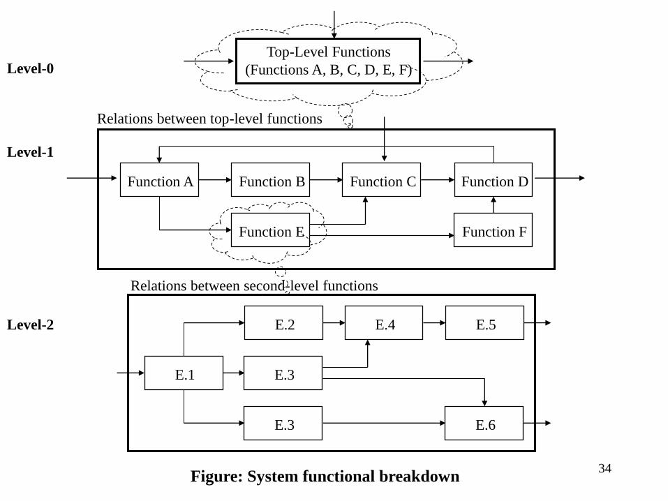
Top-Level Functions
(Functions A, B, C, D, E, F)
Relations between top-level functions
Function A Function B Function C Function D
Function E Function F
E.1
E.2 E.4 E.5
E.3
E.6E.3
Relations between second-level functions
Figure: System functional breakdown
Level-1
Level-2
Level-0
34

CASE STUDY:Clock Timer
< Step 4: Functional Decomposition >
35

Functional Architecture in ECE492
Develop:
o System Functional Breakdown at Level-0 and Level-1
o System Functional Breakdown at Level-2 (you will modify it
after proposal presentation)
Your functional breakdown must be at a such level so
that you can explain the process with greater detail
Advice:
o Pick up 2-3 operational scenarios and trace them through your
functional architecture
o Can you describe these scenarios within your functional
architecture?
o Can you describe what happens when a failure occurs?
36
STEP 5:
SYSTEM ARCHITECTURE
Step 1: Physical Architecture
Step 2: Component selection
Step 3: System Architecture diagram
37

Physical Architecture:Hierarchical Model
The Physical Architecture includes a description of the
resources that comprise the system
Hierarchy begins with the system block, system top-level
components/modules, and progresses down to the
Configuration Items (CI)
CI can be:
• Hardware or software element
• Combination of hardware and software
• People , Facilities
• Procedures, Documents
38

Physical Architecture
Ask yourself a question:
“What are physical resources needed to perform
system functions defined in functional architecture”
o Start from the top and define main modules
o Modules/components are responsible for handling specific
functionality at higher level
o Add supporting modules; such as power supply, enclosure, etc.
(Refer to requirements specification)
o Follow down by decomposing these modules into a hierarchical
tree
o Do not link these modules/components into an operational system
(not yet !)
o Do not think in terms of specific parts (!) 39
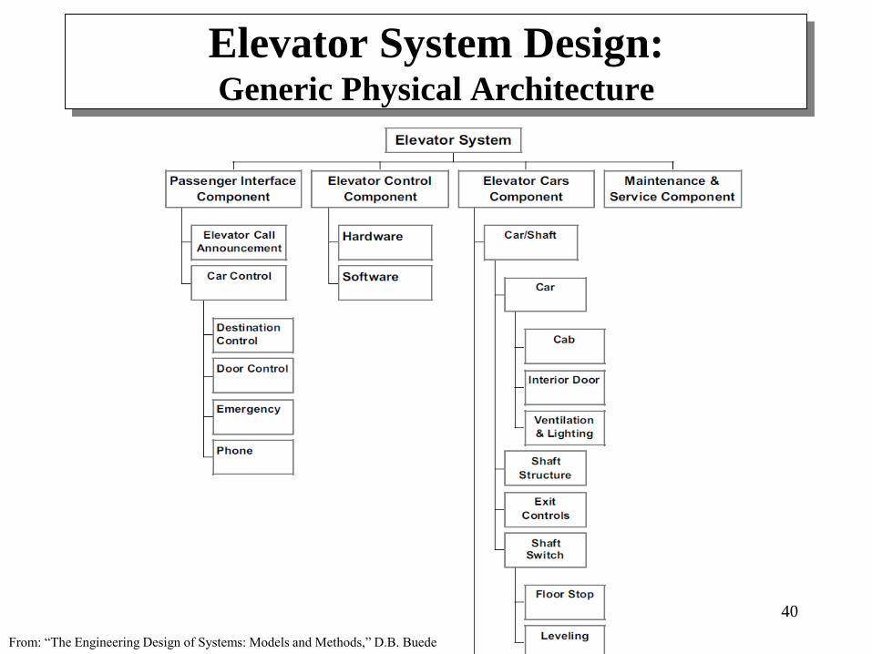
Elevator System Design:Generic Physical Architecture
40
From: “The Engineering Design of Systems: Models and Methods,” D.B. Buede

Component Selection
Search through COTS products, components, parts,
software components/modules, etc.
Select these which are needed to develop your system
o Meaning; needed to implement system functions
Identify primary components and alternatives
This selection is also guided by requirements
specification
Technology, Power, Safety and regulations, Cost
Allocate selected components to the blocks of physical
architecture
Resulting in Specific Physical Architecture
41

System Architecture
When someone says “system architecture” then it means:
This is where the final design comes together
Final product of integrating Functional Architecture, Physical
Architecture, and Requirements
o Process of Functional Allocation to subsystems
The most descriptive diagram for illustration of system
operations
Use it in your presentations and work planning
42

Functional Allocation
Group similar functions into logical subdivisions
Conversion of the “whats” into ‘hows”
Allocation to physical components – probably the most
crucial design decisions to be made
Note:
o The same functionality can be performed through different
means; for example:
• Function of signal filtering can be implemented by a
hardware or a software component
o Therefore, your system architecture will be a product of a
search through many alternatives
43

Function A Function B Function C Function D
Function E Function F
Figure: Functional allocation
Component-1 Component-2 Component-3
Component-4
44
CASE STUDY:Clock Timer
< Step 5: System Architecture >
45

Summary:
Physical Architecture in ECE492
For your Proposal:
o Physical Architecture – brief hierarchical model
o System Architecture – diagram w/ main components
For your Proposal Presentation:
o System Architecture – diagram w/ main components
Be able to illustrate a mapping of Functional Architecture
onto System Architecture
If specific parts are already known then annotate them on
the system architecture diagram46

STEP 6:
BEHAVIORAL MODELING
A system model is needed for describing system behavior,
with an emphasis on computing resources and other
resources influencing system functionality
Models are needed to describe:
o Interactivity of a system with the environment
o Man-machine interactions – how to operate a system
o Interactivity between modules – signal/data exchange, actions, etc.
Models can be used to describe system behavior at any level
– Read Chapter 6

Refer to functional decomposition and system
architecture during this modeling phase
‘Model’ – we mean a hard copy so you and your team can
see, discuss, and annotate it
o Models in your mind. . . leave for your hobbies. . .
A hard copy is a must:
To have a blueprint of system behavior
To transfer your mathematical model into its implementation
To coordinate your implementation activities around these
behaviors, and
To be able to trace them if problems occur --- and they will !

State Diagram Models
Describe the behavior of systems with memory
Intuitively, a state corresponds to an operating mode of a
system and inputs are associated with transitions between
states
Almost all systems are systems with memory – consider
startup phase, work phase, turn-off phase, sleep phase, etc.
Emphasize transition conditions between states
Excellent tool to visualize influences for systems controlled
by a microcontroller
Used at the upper abstraction level
You must have a state diagram when working with MCUs
o Helps in defining tasks and task switching mechanisms
o Manages software granularity and supports easier system integration

State Diagram for a toaster
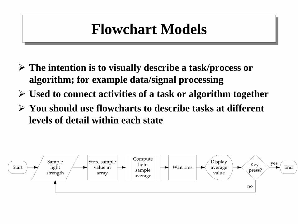
Flowchart Models
The intention is to visually describe a task/process or
algorithm; for example data/signal processing
Used to connect activities of a task or algorithm together
You should use flowcharts to describe tasks at different
levels of detail within each state
Samplelight
strengthStart
Computelight
sampleaverage
Store samplevalue in
array
Displayaverage
value
Key-press?
Wait 1ms End
no
yes
Data Flow Diagrams
Used to model the processing and flow of data inside a
system
A function oriented modeling approach
o The processes inside a DFD accept data inputs, transform
them in some way, and produce output data
Differs from Flowcharts – it does not encapsulate
control and sequencing information, but allows
multiple processes running concurrently
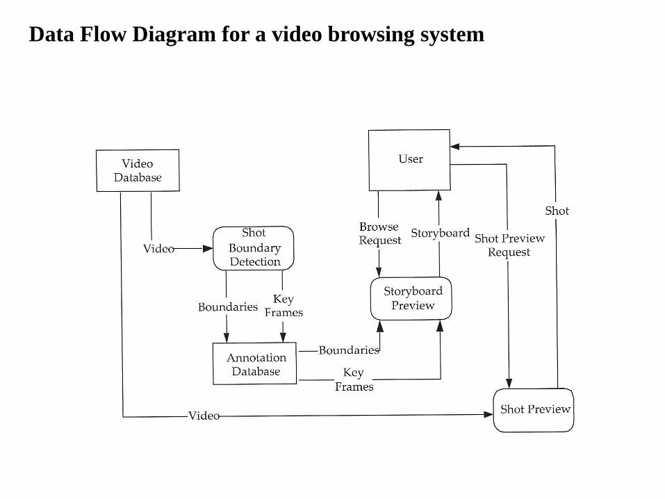
Data Flow Diagram for a video browsing system

CASE STUDY:Clock Timer
< Step 6: System Modeling >
Summary:
Behavioral Models in ECE492
Selection of a modeling method highly depends on project
type
o Most projects will require at least two modeling methods (e.g.,
state diagram, and flowcharts)
Virtually all projects involving microcontrollers require a
state diagram as a top level model
Systems with even a primitive multi-tasking require
models for:
o Task switching (task diagram)
o Resources utilization (memory map)
Do not procrastinate and design a system in the right way

STEP 7:
BACKGROUND FOUNDATIONS
Just having a design is not enough to carry out a professional
engineering project
Professional approach
System design
+
Mathematical modeling System implementation
+
Simulation
You need to avoid a ‘hobby shop’ approach
Design, Modeling, and Simulation
Goals:
o Theoretically verify your approach
o Verify equations you use
o Determine behavioral functionality and parameter ranges
o Remove uncertainty of a project failure
This applies to many components of your system; for
example:
o Filter component
o Control component
o Power supply component
o Signal processing component
o etc.

Example: Control Component
Use functional/physical decomposition to determine system
structure
Assign simple mathematical equations to each
physical/functional element
(this helps to handle complexity and allows for easier
simulation, implementation, and debugging)
DC Motor
Kv, KT
K
B
J
θ
Tl
Gears
rPotentiometer
Kp
Power Amp.
KTa
VmVaVr
-

Why Simulation?
There is no better method for verifying your approach
o You can be spectacularly wrong in your assumptions
o System behavior can be completely different than your ‘gut feeling’
o How many times you made a mistake in math equations?
There is no better method for finding parameter
combinations
Running multiple real-time experiments with your product is not an
answer – it is a ‘hobby shop’ approach
Break from the notion that it is time consuming
o Use professional modeling/simulation software suites
o Start with Matlab !
Distinguish RIGHT approach from WRONG one
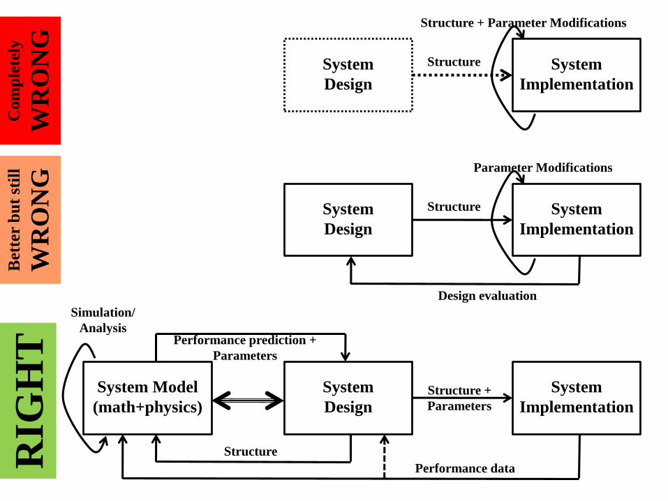
System Model
(math+physics)
System
Design
System
Implementation
Performance prediction +
Parameters
Structure
Performance data
Structure +
Parameters
Com
ple
tely
WR
ON
GR
IGH
TB
ette
r b
ut
stil
l
WR
ON
GSystem
Design
System
Implementation
Structure
Structure + Parameter Modifications
System
Design
System
Implementation
Structure
Parameter Modifications
Design evaluation
Simulation/
Analysis

CASE STUDY:Clock Timer
< Step 7: Project Background Foundations >
Summary:
Background Foundations in ECE492
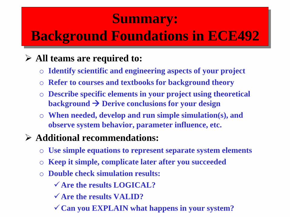
All teams are required to:
o Identify scientific and engineering aspects of your project
o Refer to courses and textbooks for background theory
o Describe specific elements in your project using theoretical
background Derive conclusions for your design
o When needed, develop and run simple simulation(s), and
observe system behavior, parameter influence, etc.
Additional recommendations:
o Use simple equations to represent separate system elements
o Keep it simple, complicate later after you succeeded
o Double check simulation results:
Are the results LOGICAL?
Are the results VALID?
Can you EXPLAIN what happens in your system?

STEP 8:
EARLY PROTOTYPING
Early prototyping report is due at your Design Review
Presentation
Extensive report must be included in your Detail Design
Report
You will eventually need to extend early prototyping
activity into the first 1-2 weeks of ECE-493
o But no longer than that
o After that you should have no more questions regarding your
design and components
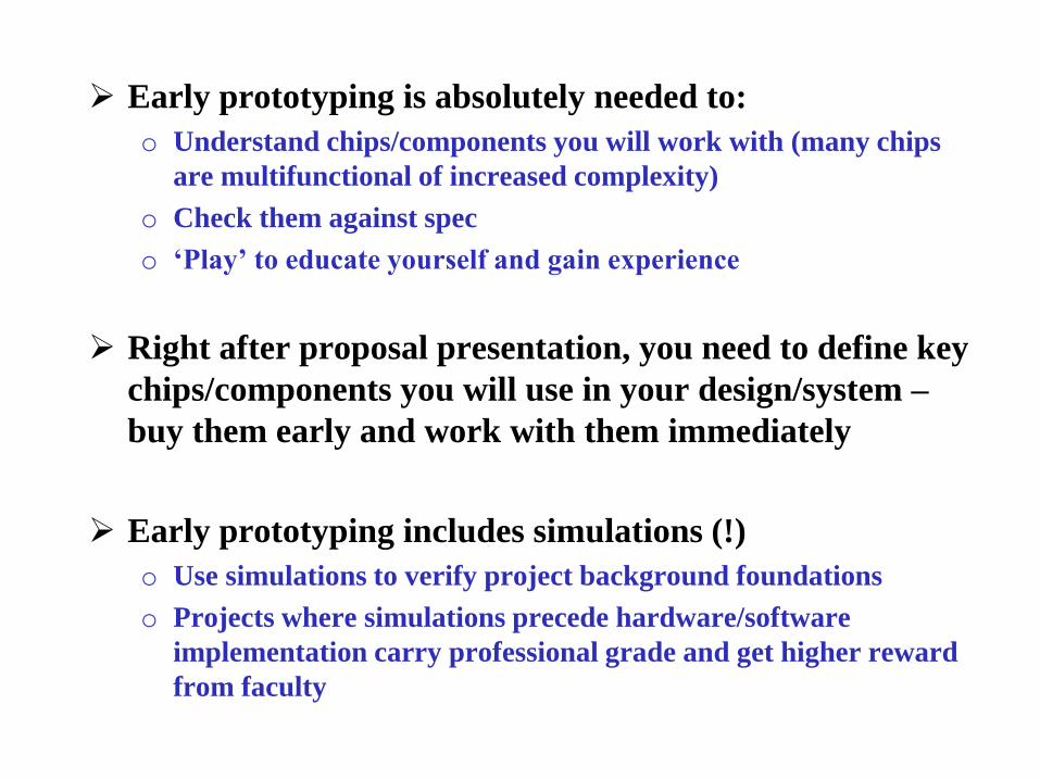
Early prototyping is absolutely needed to:
o Understand chips/components you will work with (many chips
are multifunctional of increased complexity)
o Check them against spec
o ‘Play’ to educate yourself and gain experience
Right after proposal presentation, you need to define key
chips/components you will use in your design/system –
buy them early and work with them immediately
Early prototyping includes simulations (!)
o Use simulations to verify project background foundations
o Projects where simulations precede hardware/software
implementation carry professional grade and get higher reward
from faculty
CASE STUDY:Clock Timer
< Step 8: Early Prototyping >

STEP 9:
DESIGN DOCUMENT
There is not much time left – so hurry up
The focus is on detailed design
o Emphasize the top-down design
o Get to the bottom – circuit-level, algorithm-level, etc. (!!!)
Technical part and administrative part
o Administrative issues depend on technical design
o Again, you must have technical issues resolved before addressing administrative issues
Look back at your proposal
You must report your early prototyping activity

REMINDER (!)
For successful completion of ECE492 you must have
all four issues resolved in your Design Document:
1) Detailed design of your system
Schematics down to the component/resistor/capacitor value
Algorithms
2) Model of your system operations
Functional model
System architecture
3) Prototyping effort progress
Simulations
Experimentation with selected components
4) Implementation plan
Gantt chart for the next semester effort
List or tasks and team member allocation/responsibilities

Design Document Format
Cover page
Short introduction (Problem Statement)
Requirements specification
System design/architecture - system decomposition
Background knowledge/phenomenology (math, physics, EE,
etc.) used to derive a solution/design
Detailed design
1) All levels of your design down to circuit schematics, state diagrams,
and algorithm flowcharts – even if you are not sure about the design
2) Detailed description of components and interfaces
3) Include flow diagrams with identification of subroutines and main
parameters for simulation projects
4) Detailed description of software structure
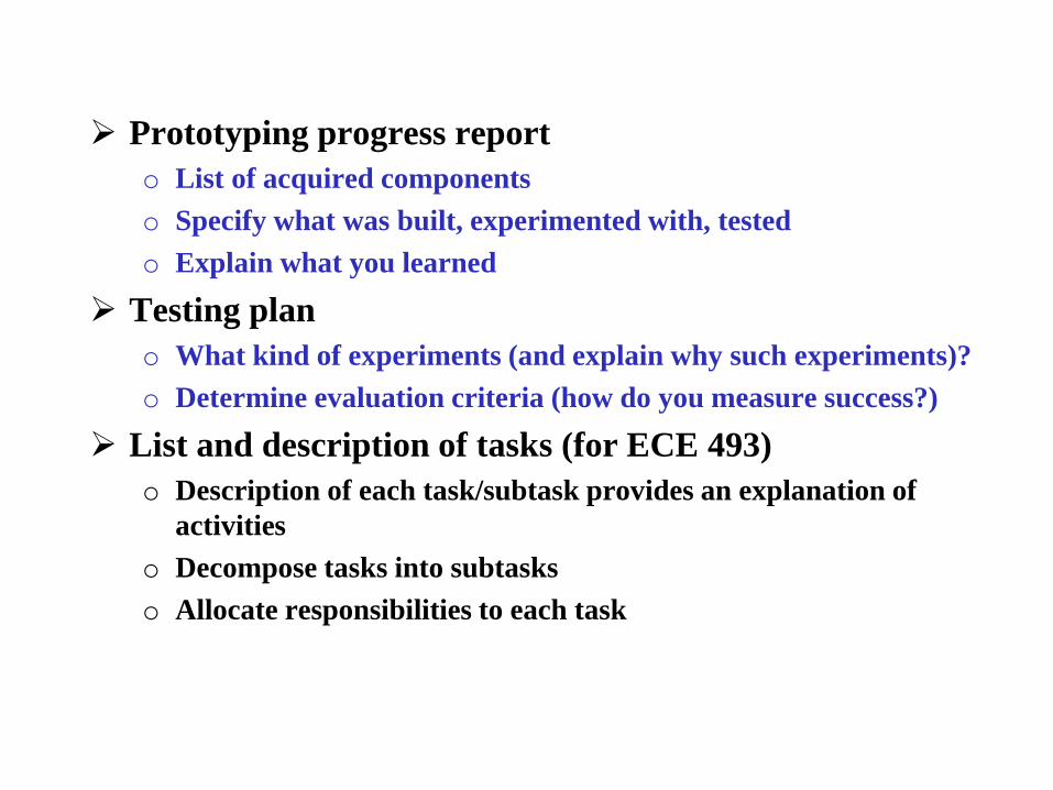
Prototyping progress report
o List of acquired components
o Specify what was built, experimented with, tested
o Explain what you learned
Testing plan
o What kind of experiments (and explain why such experiments)?
o Determine evaluation criteria (how do you measure success?)
List and description of tasks (for ECE 493)
o Description of each task/subtask provides an explanation of
activities
o Decompose tasks into subtasks
o Allocate responsibilities to each task

Schedule and milestones
o Cover the next semester time (+ summer/winter break if you
plan to work)
o Be realistic
o Make a significant push at the beginning of the next semester
Begin working during Wekk#0
Exploit the first few weeks of very light class schedule
Remember, most projects are delayed
o Include demos – mention functionalities to be presented by a
sequence of demos/experiments
o See sample schedule on the web page

CASE STUDY:Clock Timer
< Step 9: Detailed Design >

STEP 10: TESTING PLAN
Systems must be tested to ensure that they meet the engineering requirements
Testing is used to:
o Verify system functions and performance against requirements
o Uncover design flows
o Find implementation errors (and bugs)
o Understand system’s reliability
Testing frequently requires building a separate system dedicated to the execution of tests and collection of test data

Systems are tested for a variety of conditions and many combinations of conditions
o But, for complex systems, it’s almost impossible to test against all combinations of conditions
Testing can be time consuming and costly, but at the end, testing saves money – (e.g., Hubble Telescope)
The costs of corrections is lower before systems are deployed
Testing must be considered throughout system implementation and integration – such testing can save your project !

Testing Principles
Testing begins at a
design process
o Write test cases to check
requirements spec
o Write test plan while
designing modules
o Write test plan for
module integration
o Perform
testing/debugging while
implementing modules
The Test-Vee illustrates
this process
RequirementsSpecification
SystemDesign
Construct
Debugging
UnitTest
IntegrationTest
AcceptanceTest
Development Testing
Tes
t p
lan
an
d T
est
case
s

Every level of design has a corresponding level of testing
Notice added arrows – they emphasize that
o The left side develops a plan at a given level, while
o The right side executes the test plan accordingly
An acceptance test must be written to test against
requirements specification
You will need to develop test cases early next semester

Influence of Test Planning on
System Design
Test cases define exactly what the system/module must do
Testing prevents “feature creep”
Test cases motivate developers by providing immediate
feedback
Test cases force designers to think about extreme
situations
Test cases force the designer to re-consider the design of
the module before building it
Test cases are a form of documentation and an integral
part of contract obligations (!)

Dos and Don’ts for ECE-492/3
Too many ECE-492/3 projects are finished with
o Very limited testing (NOT GOOD)
o A demo of “See, it works” attitude – THIS IS NOT ACCEPTABLE !
o Ad hoc testing plan implemented at the end (NOT GOOD)
o No data diagrams, statistical analysis, etc. (NOT GOOD)
Advice
o Spend a lot of time on testing – to develop a powerful statement “We
succeeded” rather than “It works”
o Collect data. Process data using statistical analysis. Show diagrams.
Derive conclusions and discuss performance and problems.
o Answer to: “Tell me when your system fails” - but use quantitative
data, diagram of process test data, or similar. Don’t use intuitive
explanations.

Types of Test
Black box tests
o No knowledge of internal organization
o These tests can be more challenging
o Only access to inputs and outputs
o Change inputs and observe outputs
White box tests
o Knowledge of internal organization
o Tests target specific internal nodes of the system to check that
they are operating as expected
o Create test instances which reveal physical or logical errors

Constructing Tests
Four different types of tests shown in the Test-Vee figure
o Debugging
o Unit testing
o Integration testing
o Acceptance testing
Additional motivation
Testing reduces the number of bugs
Tests reduce the cost of change
Tests improve design
Tests allow you to change and optimize components
Testing forces you to slow down and think more (!)
Testing makes development faster
Tests reduce fear

Experimentation Plan
You need to include a short experimentation plan in your
Design Document – it’s required (!!!)
In the discussion, focus on:
o Which top-level functionalities you want to test
o Method of testing leading to an answer “we succeeded”, “we are
close”, or “not so”
o Designing experiments which will give you quantitative data; so
you can process and derive conclusions
o Type of graphs demonstrating your test/processed data

CASE STUDYClock Timer
< Step 9: Testing >

Summary:
Testing Plan in ECE492
Start with the development of an acceptance test
o A test which will verify two or three system requirements
o Focus on performance requirements (easiest to demonstrate; will
give you the most powerful justification of a success)
Define a simple test case; next move on to a more
challenging test case
Think immediately what data you need to collect and how
to collect them
Do not write too ambitious plan (too many tests)
Instead focus on few tests but explain them in greater
detail (sometimes, less is more)
Keep data from debugging and integration (just in case)

STEP 11:
PROJECT MANAGEMENT
Motivation
o Engineers are regularly engaged in projects in their careers
o Middle management continues to shrink
o Industry now organizes more around projects than functions
o Engineers have led the way on project management, it is now
“hot and trendy”
o According to a survey: #1 required skill for new engineers =
Project Management Skills
o This has more to do with all team members understanding
project management aspects rather than being a manager (!)

Project Management Objectives (!)
To complete the project:
On-time
Within budget
So that it meets the requirements
Work Breakdown Structure
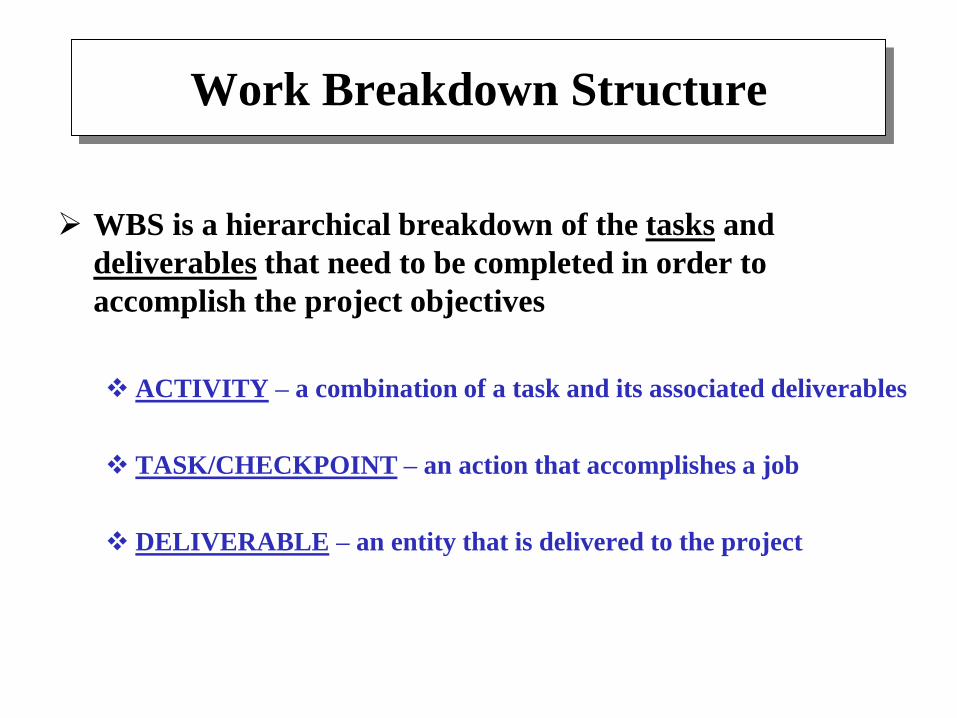
WBS is a hierarchical breakdown of the tasks and
deliverables that need to be completed in order to
accomplish the project objectives
ACTIVITY – a combination of a task and its associated deliverables
TASK/CHECKPOINT – an action that accomplishes a job
DELIVERABLE – an entity that is delivered to the project

ACTIVITY
An ACTIVITY must have:
Definition of the work to be done
Timeframe for completion of the activity
Resources needed
Person responsible for the activity
Predecessors – other activities to be completed before
Checkpoints for monitoring the progress

Graphical Visualization of the Project
Gantt chart
Preferred method for project visualization
Developed by Henry Gantt (1861-1919) – a bar graph
representation of activities on a timeline
Frequently, each activity must be complemented by a
numeric Task Completion Rate (in percentages)
Include “Milestones” – major in-progress demos given
to your FS
See Figure 10.3

ID
Task Name Start Finish DurationJan 2005 Feb 2005
1/16 1/23 1/30 2/6 2/13 2/20 2/27
1 32d2/22/20051/10/20051: Interface Circuitry
2 14d1/27/20051/10/20051.1: Design Circuitry
3 10d2/10/20051/28/20051.2: Purchase Components
4 8d2/22/20052/11/20051.3: Construct & Test Circuits
5 2d2/14/20052/11/20051.3.1: Current Driver Circuitry
6 3d2/15/20052/11/20051.3.2: Level Offset & Gain Circuitry
7 5d2/22/20052/16/20051.3.3: Integrate Components
8 23d2/9/20051/10/20052: LED & Driver Circuitry
9 1d1/10/20051/10/20052.1 Research A/D Converters
10
7d1/19/20051/11/20052.2 Complete Hardware Design
11
10d2/2/20051/20/20052.3 Purchase LED & Driver Components
12
5d2/9/20052/3/20052.4: Construct & Test
13
7d3/3/20052/23/20053: System Integration & Test

You can use the following simplified version of Gantt charts
1. Robot hardware development
Task NameWeeks
1
1.1 Platform construction
2 3 4 5 6 7 8 9 10 11 12 13 14
Completion
Rate
100%
100%
100%
100%
0%
65%
75%
0%
Reporting Period
Project Planning Chart
1.2 Motion system development
1.3 Short-range sensor system development
2. Motion control system development
2.1 Micro-processor system integration
2.2 Motion control software programming
2.3 Motion control system integration
3. Experimentation and testing
3.1 Testing robotic platform
3.2 Experiment #1
3.3 Experiment #2
4. Uprade #1 implementation
4.1 Long-range sensor system development
4.2 Long-range sensor integration
4.3 Testing and Experiment #3
5. Commercial applications analysis
6. Demonstration (milestones)
7. Reporting
100%
100%
100%
0%
0%
CASE STUDY:Clock Timer
< Step 10: Work Breakdown Structure>

Summary:
Project Management in ECE492
Build the plan after your design is almost complete
Take the initial time estimates for activities and extend
them almost by ~30%
Assign a lot of time for testing and integration
Factor in lead times for part ordering
Do not assign all team members to all tasks
Experience counts
Next semester – you need to resubmit your revised WBS