ringmaster nov07 se6251
DESCRIPTION
electricalTRANSCRIPT
Ringmaster rangeindoor/outdoor switchgearInstallation, operation and maintenance instructions
07November


1SCHNEIDER ELECTRIC
page
Contents
Version 11 - Issue date November 2007Note: This manual covers ring main units produced from June 1999. Designation RN2c/RN6c/RE2c. For ring main units designated RN2/RN6 see earlier manual.Ref: Version 005/December 98.
Commissioning
Checks and tests
Tests
Commissioning Ringmaster
with VIP 300
Ringmaster operation
RN2c, RE2c, RN6c essential checks
Features
Switch and circuit breaker
Earth switch
Cable testing
Circuit breaker reset
Motorpack
Motorpack operation
Neon indication
Ringmaster range operation
Main features
Switch and circuit breaker
Earth switch
Cable testing and actuator control
Actuator control
Maintenance
Recommendations and conditions
Housing
Circuit breaker
54
54
55
65
69
69
70
71
72
73
75
76
77
78
79
80
81
82
83
84
85
85
86
87
General
Symbols and meanings
Schneider Electric at your service
General description
Handling, transportation and storage
Storage
Goods receiving
Characteristics
Civil engineering
Floor preparation
Internal arc
Cable trench
Installation
Transformer mounting
Connecting the HV cables
Erection / connection
Installation of pilot cables
Removal of VIP relay
Accessing VT’s
Earth fault flow indicator
Actuators
Accessories
Fitting REC2 to Ringmaster range
Protection
Time fuse link
Operation
VIP300
VAP6
2
2
3
4
5
6
7
8
9
9
10
12
13
14
15
20
22
23
24
25
26
27
28
43
43
44
46
52
page

2 SCHNEIDER ELECTRIC
GeneralSymbols and meanings
! DANGER
WARNING
CAUTION
The following symbols appear in this document to indicate the degree of hazard according to the situation.
Danger: Failure to follow this instruction will result in death, seriousinjury or equipment damage
Warning: Failure to follow this instruction can result in death, seriousinjury or equipment damage
Caution: Failure to follow this instruction can result in equipment damage
Information: We draw your attention to this particular point

3SCHNEIDER ELECTRIC
GeneralSchneider Electric at your service
Customer service and aftersales support
Services and projects
Document guidelines
Safety requirements
All operations described hereafter must be carried out by respecting the safetyrequirements in full, under the responsibility an authorised person.
Personnel undertaking installation and commissioning must be competent and understand local regulations and standards.
If the installation and operational team is unsure or not familiar with Ringmaster orRingmaster Range switchgear please contact Schneider Electric.
CAUTION
CAUTION
! DANGER
For technical support or advice current products please contact our customer service department:Tel: +44 (0) 113 290 3651Fax: +44 (0) 113 290 3710Email: [email protected]
For the following services please contact Services & Projects:
■ Spares and managed spares contracts■ Maintenance and service contracts■ Retrofit■ Installation■ Testing and commissioning■ System design■ Training
Tel: +44 (0) 113 290 3634Fax: +44 (0) 113 290 3777Email: [email protected]
This document is not a commercial document, but a technical document prepared bySchneider Electric.
The objective of this publication is to assist with the correct installation and operationof Ringmaster and Ringmaster Range.
Reproduction either in full or partial of this document is prohibited and can only beundertaken with permission of Schneider Electric.

4 SCHNEIDER ELECTRIC
GeneralGeneral description
These instructions cover all operations concerning handling, installation, operation
and maintenance of the Ringmaster Range of equipment.
Introduction
RN2c/RE2cRN6c
CN2 SN6 CE6 SE6 CE2 MU6+CE6/CE2/SE6
MU2 MU6
1510 1610hWI
average dimensions(mm) (packed)
unit(s)
approx. weight (kg)
771842350
1750520960280
1750520960280
1750520960280
1750520960280
1750520960280
175011001100520
1650520960240
1750520960240
When fully installed the equipment is suitable for outdoor use. It may therefore be necessary to protect the equipment from the environment duringerection/commissioning. Please check equipment specification for clarification ofindoor/outdoor use. Should the busbar chamber or cable box become exposed tothe elements, they should be thoroughly cleaned prior to energising.
The range comprises:-■ RN2c 630/200A non extensible compact ring main unit■ RN6c 630/630A non extensible compact ring main unit■ RE2c 630/200A extensible compact ring main unit■ CN2 200A non extensible circuit breaker ■ SN6 630A non extensible switch■ CE2 200A extensible circuit breaker ■ CE6 630A extensible circuit breaker ■ SE6 630A extensible switch■ MU2 200A feeder metering unit non-extensible units■ CE2/CE6/SE6 with metering unit
Compact non extensible composite ringmain unit ■ RN2c 630/200A■ RN6c 630/630A
Weights and dimensions
Extensible circuit breakers and switches ■ CE2 200A■ CE6 630A■ SE6 630A
Please refer to the appropriate pages in the Ringmaster selection guide Ref:MGMV5337 available from Schneider Electric or on line at www.schneider.co.uk

5SCHNEIDER ELECTRIC
GeneralHandling, transportation and storage instructions
Transport & handling
Storage
CAUTION
CAUTION
Ringmaster is only suitable for outdoor storage when packaged correctly or fullycommissioned.The type of gland supplied will vary in accordance with specific contract requirements.The style of packaging will vary in accordance with the method of transportationand specific contract requirements.Please consult your commercial documentation to see how this equipment ispacked.
Highcentre ofgravity
Use lifting lugsONLY to liftRingmaster
Use all four lifting points
Do not stand on Ringmaster
Do not put anything on Ringmaster
All units can be off loaded by fork lift truck using the transport pallet. They can also be off loaded using the lifting lugs fitted at the top of the unit.
Units can be carried on open topped trucks or stored outside for short periods provided that all apertures are covered. Units should not be considered weatherproof until the paint work has been inspected and, if necessary any damage should be re-touched. Please refer to paintwork on page 7 for repairingdamaged paintwork.If units are to be stored for long periods of time they should be stored in a warm,dry location and protected against dust and debris.

6 SCHNEIDER ELECTRIC
GeneralStorage
All units are delivered on pallets (secured by 4 x M8 screws and nuts) and fitted
with lifting eyes, suitable for off loading by forklift truck or overhead crane.
Ancillary kits containing busbar, dyscon boots, glands, screws etc. are supplied
loose with each unit or fastened to the panel leg or secured in the cable boxes.
Following transportation ensure circuit breaker mechanism is reset prior to
operation.
It is recommended that prior to energising the unit all protection device are
checked to ensure they are set correctly. For TFL units ensure fuses are fitted.
VIP units must be set in accordance with the results of a protection co-ordination
study.
Off loading
Ancillary kits
Prior to operation
Prior to energising

7SCHNEIDER ELECTRIC
GeneralGoods receiving
In the event of an anomaly, please contact the transport/shipping company.
The functional unit must remain on its base, in its original packing, during storage, and until installation.
In the event of any anomaly or apparent damage, do not install, please contact SCHNEIDER ELECTRIC.
Contact details: are detailed on page 3.
Check for any damaged paintwork. Damaged areas should be cleaned and re-coated as follows:
Rub down the area around the damage with medium glass paper. Clean the damaged area with emery paper ensuring the surface is clean and free of any corrosion. Apply one coat of zinc-rich epoxy primer (a two-pack system is recommended), the coating to be 35-45 microns thick. The recommended paintsystem is International Paints “Interzinc EPA 072 and EPA 073”.
Leave to cure for 24 hours, then apply two, 35-45 micron coats (ie 70-80 microns in total) of two-pack polyurethane, Interphane PFR 764 is recommended.
The standard colour employed is Dark Grey Code 632 to BS 381C:1996.
CAUTION
Goods receiving ■ Before any equipment is accepted it should be inspected carefully for damage or loss incurred during transit
■ Where possible check the presence of accessories against the packaging list
■ Where possible check the information on the nameplate(s) and compare against the order confirmation
■ The packing must be in place and in good condition at the time of receipt. Wherever possible, damage should be recorded, photographed and witnessed.It may be necessary to unpack the equipment to establish the full extent of the problem.
Paintwork
8 SCHNEIDER ELECTRIC
GeneralCharacteristics
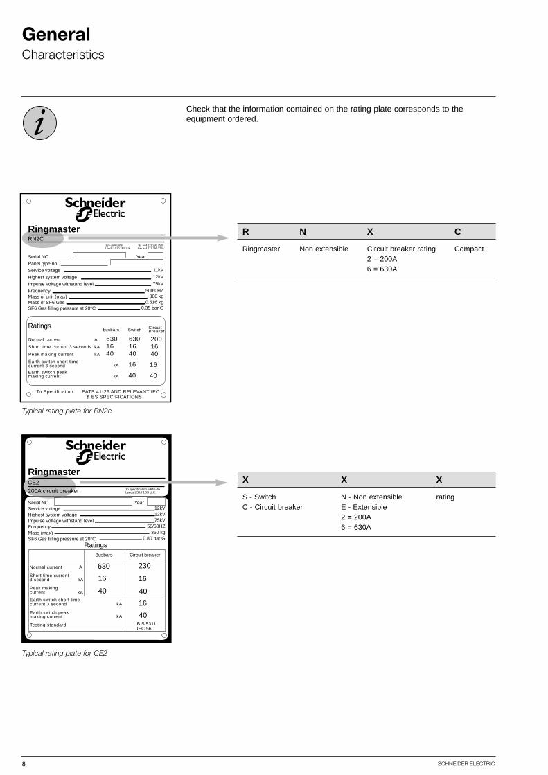
Check that the information contained on the rating plate corresponds to the equipment ordered.
Typical rating plate for RN2c
Serial NO.Panel type no.Service voltageHighest system voltageImpulse voltage withstand levelFrequencyMass of unit (max)Mass of SF6 GasSF6 Gas filling pressure at 20°C
11kV12kV75kV
50/60HZ300 kg
0.516 kg0.35 bar G
Year
Normal current
Short time current 3 seconds
Peak making current
Earth switch short timecurrent 3 second
Ratings
RingmasterRN2C
123 Jack LaneLeeds LS10 1BS U.K.
A
kA
kA
6301640
kA
kA
6301640
2001640
16
40
16
40
busbars Switch CircuitBreaker
To Specification EATS 41-26 AND RELEVANT IEC & BS SPECIFICATIONS
Tel +44 113 290 3500Fax +44 113 290 3710
Earth switch peakmaking current
R N X C
Ringmaster Non extensible Circuit breaker rating Compact2 = 200A6 = 630A
Typical rating plate for CE2
Serial NO.Service voltageHighest system voltageImpulse voltage withstand levelFrequencyMass (max)SF6 Gas filling pressure at 20°C
12kV12kV75kV
50/60HZ350 kg
0.80 bar G
Year
Normal current
Short time current3 second
Peak makingcurrent
Earth switch short timecurrent 3 second
Earth switch peakmaking current
Testing standard
A
kA
kA
kA
kA
630
16
40
230
16
40
16
40B.S.5311IEC 56
Busbars Circuit breaker
Ratings
RingmasterCE2
200A circuit breaker To specification EA41-26Leeds LS10 1BS U.K.
X X X
S - Switch N - Non extensible ratingC - Circuit breaker E - Extensible
2 = 200A6 = 630A

9SCHNEIDER ELECTRIC
Civil engineeringFloor preparation
Floor preparation, equipment fixing dimensions and main cable position can befound in the Ringmaster selection guide reference MGMV5337. Or, if supplied the arrangement drawing for the switchboard or unit.
Where it is not possible to guarantee that the floor is within the specified tolerance,we strongly recommend the use of foundation channels, i.e. Unistrut P3270 or similar.
Note: The floor must be 1mm below the top of the Unistrut.
jigs supplied
channels grouted in
4170
position using setting
41
foot of unit
m10 channel fixing
in subfloorchannels made
channel nut
to + - 1mm with
spring loaded
foundation channel
note: floor level flush
Both non extensible units and switchboards can be directly bolted to the concretefloor by use of 4 x 10mm (supplied) UNI-FIX or similar rag bolt fixings - see diagram. The floor tolerance for extensible switchboards is ±1mm over 1metre.

10 SCHNEIDER ELECTRIC
Civil engineeringInternal arc
Ringmaster
Modular Ringmaster range
Internal arc
Kits to safely divert the flow of gassesoutside the substation are not part ofthe supply of equipment. If required,kits will need to be adapted to eachsituation.
Internal arc withstand
12.5kA, 16kA and 21kA for 1 second
Arrows indicate direction of exhaustgases
CAUTION
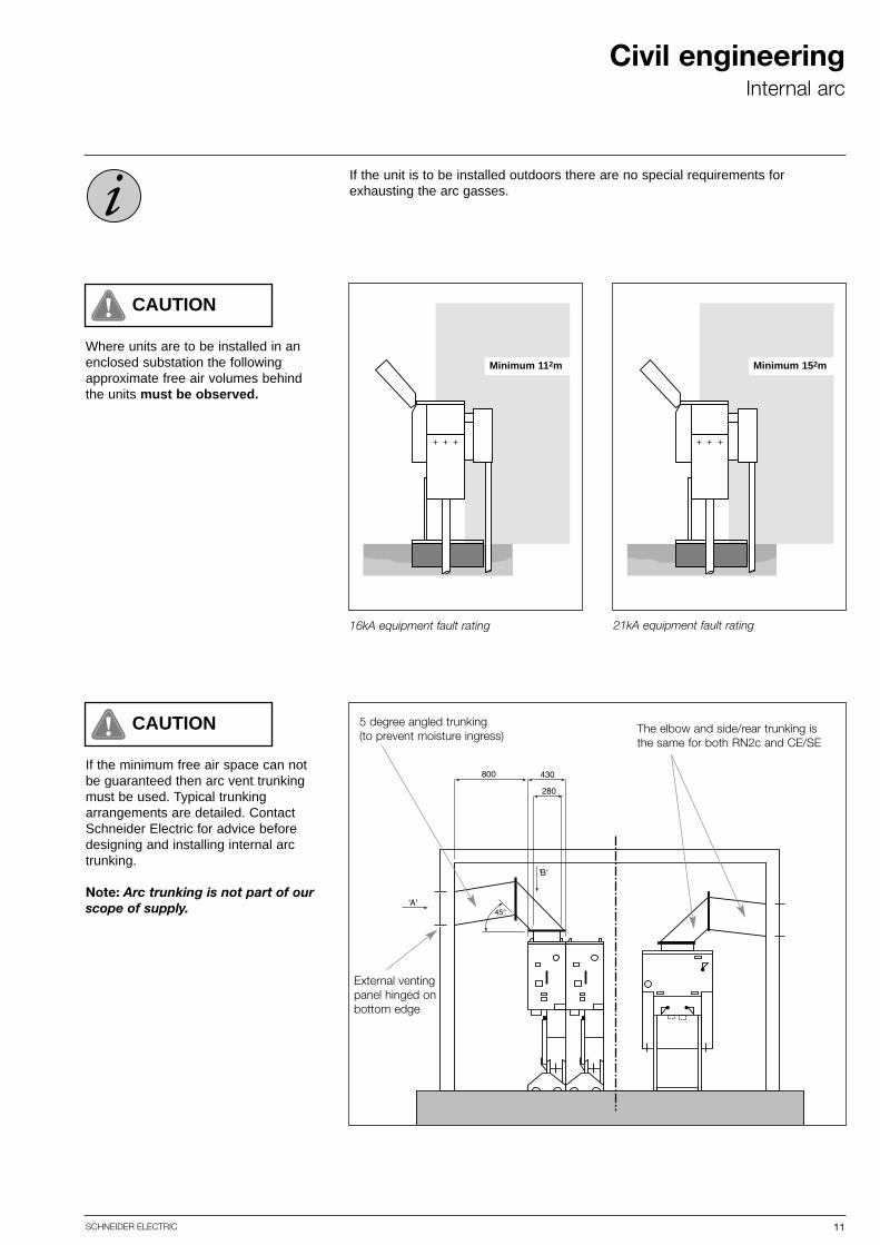
Where units are to be installed in anenclosed substation the following approximate free air volumes behindthe units must be observed.
11SCHNEIDER ELECTRIC
Civil engineeringInternal arc
CAUTION
If the unit is to be installed outdoors there are no special requirements for exhausting the arc gasses.
If the minimum free air space can notbe guaranteed then arc vent trunkingmust be used. Typical trunkingarrangements are detailed. ContactSchneider Electric for advice beforedesigning and installing internal arctrunking.
Note: Arc trunking is not part of ourscope of supply.
CAUTION
16kA equipment fault rating 21kA equipment fault rating
Minimum 112m Minimum 152m
5 degree angled trunking (to prevent moisture ingress)
External ventingpanel hinged onbottom edge
The elbow and side/rear trunking isthe same for both RN2c and CE/SE
12 SCHNEIDER ELECTRIC
Civil engineeringCable trench
16675
7
1320
trenchmaincable
45
16675
7
1320
trench maincable
45O
front entry rear entry
53313
20
max. trench width
56097 97
1630 20
42
223.
5
cabl
e bo
x ta
ll le
ngth
54.5
928 735
695
door
operatinghandle
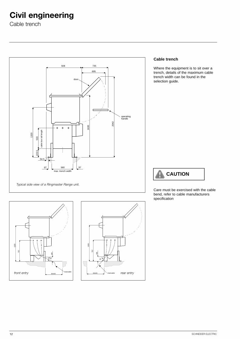
Cable trench
Where the equipment is to sit over atrench, details of the maximum cabletrench width can be found in the selection guide.
Care must be exercised with the cablebend, refer to cable manufacturersspecification
CAUTION
Typical side view of a Ringmaster Range unit.

13SCHNEIDER ELECTRIC
Installation
CAUTION
Standard units can be installed in environments which meet ‘normalservice conditions’ as defined by IEC 60694 section 2.1:-
Ambient temperature: -25°C to +45°CAltitude: up to 1,000 meters above sea level
If the location is outside the certified parameters please refer to the selection guide,alternatively contact Schneider Electric for advice. Where the units are to beinstalled in environments where the above parameters are exceeded, this must bedeclared to Schneider Electric so the appropriate de-rating factors can be applied.
Failure to rate the equipment to the location may result in equipment failure.
CAUTIONUnits may be installed indoors or outdoors but must not be subjected to regularextremes of weather e.g. heavy rain storms, heavy snow and ice, flooding, temperature cycles not greater than 55°C and less than -25°C, dense coastal fogor acid rain.

14 SCHNEIDER ELECTRIC
InstallationTransformer mounting
771
30
771
600
973
537
510
40
1510
4 OFF M10*115RAWL THROUGHBOLTS
213 213
267
263
105
385.5
569
1955
516
1320
936
385.5
105
ES
I35-
1 tr
ansf
orm
er
470
86 86 86 86 86
89
89216370 116
Dimensions of the EA transformer flange
General arrangement of a transformer mounted RN2c.
14 x M12 clearance holes
Adjust RMU stand height to suit. Under workshop conditions remove transformer lidscrews. Pump oil out to below HV pocket height. (Pump into clean, dry drum).Remove blanking plate. Push units together. Insert bushing gasket and make firm connections on flanges and support brackets. Make off the 3 phase connectionschecking that these are tight and in the correct phase sequence, onto the M12 copper studs in the bushings. Pump clean oil back to the cold oil fill levelmarked on the transformer oil gauge. Re-fit tank cover ensuring that there is nodamage to the gasket. Touch up paint as necessary.
Perform primary winding resistance test in insulation resistance test.
WARNINGImportant when coupling transformerM12 transformer termination lug tightening torque - 25Nm

15SCHNEIDER ELECTRIC
InstallationConnecting the HV cables
The RN2c/RE2c/RN6c is suitable foraccepting 1 x 3 core or 3 x 1 corecable up to 240mm2 copper or aluminium approaching from below -top entry available on request. Fit the gland plate and accessories inaccordance with the instructions supplied with the ancillary kit.
Standard RN2c/RE2c/RN6c cable box
Angled gland plates can be provided on all units to the front or rear, in orderto simplify civil works.
Please refer to accessory kit instructionsfor details.
Standard CE, CN, SE & SN cable boxStandard cable entry directly from below
WARNING
Connecting the HV cablesForeward
Before connecting the cables, ensure that each unit is in the earthed switch position.
The cables MUST be connected with the equipment securely fixed to the ground.The operations described below apply to apply to all types.
The connections used should be made and used according to the manufacturersinstructions.
Connecting Ringmaster frame to the substation earthBefore connecting the HV cables you must connect the Ringmaster frame to themain earth bar.
Access to the HV connection bushingsCable box venting fixings arrangementEnsure cable box cover screws are configured correctly as detailed on cable boxcover label.

16 SCHNEIDER ELECTRIC
InstallationConnecting the HV cables
CE2, CE6, SE6, CN2, SN6 top cable entry
CE2, CE6, SE6, CN2, SN6 angled cable entry
16675
7
1320
trenchmaincable
45
16675
7
1320
trench maincable
45O
CE2, CE6, SE6, CN2, SN6 with top entry cable box.
front entry rear entry
Top entry cable boxes can be fitted forbasement substation applications.
17SCHNEIDER ELECTRIC
InstallationConnecting the HV cables
WARNING
! DANGER
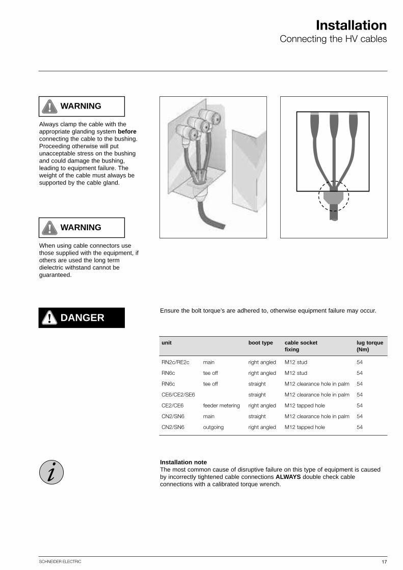
Always clamp the cable with theappropriate glanding system beforeconnecting the cable to the bushing.Proceeding otherwise will put unacceptable stress on the bushingand could damage the bushing, leading to equipment failure. Theweight of the cable must always besupported by the cable gland.
WARNING
When using cable connectors usethose supplied with the equipment, ifothers are used the long term dielectric withstand cannot be guaranteed.
Ensure the bolt torque’s are adhered to, otherwise equipment failure may occur.
unit boot type cable socket lug torquefixing (Nm)
RN2c/RE2c main right angled M12 stud 54
RN6c tee off right angled M12 stud 54
RN6c tee off straight M12 clearance hole in palm 54
CE6/CE2/SE6 straight M12 clearance hole in palm 54
CE2/CE6 feeder metering right angled M12 tapped hole 54
CN2/SN6 main straight M12 clearance hole in palm 54
CN2/SN6 outgoing right angled M12 tapped hole 54
Installation noteThe most common cause of disruptive failure on this type of equipment is causedby incorrectly tightened cable connections ALWAYS double check cable connections with a calibrated torque wrench.

18 SCHNEIDER ELECTRIC
InstallationConnecting the HV cables
WARNINGWhen cabling please ensure that the correct phase rotation is followed for all medium voltage cable boxes.
When connecting two cables per phase on RN2c and RN6c on a single bushinguse the termination kit supplied by Schneider Electric. For all other units contactSchneider Electric for advice before proceeding.
CAUTION
✔✕
There are phase identification stickers in all accessible points throughout the equipment.
Double cable arrangement using the ECONcable termination kit
19SCHNEIDER ELECTRIC
InstallationConnecting the HV cables
✕ ✕ ✕
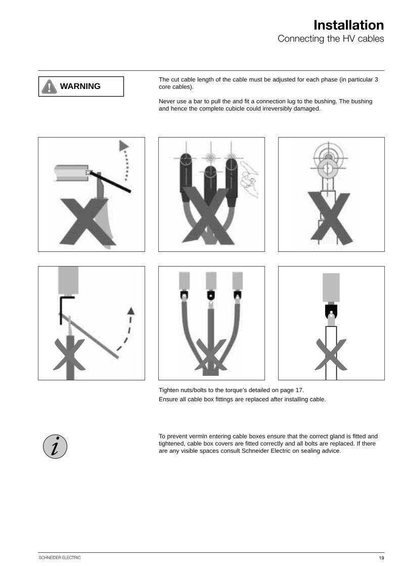
WARNINGThe cut cable length of the cable must be adjusted for each phase (in particular 3core cables).
Never use a bar to pull the and fit a connection lug to the bushing. The bushingand hence the complete cubicle could irreversibly damaged.
To prevent vermin entering cable boxes ensure that the correct gland is fitted andtightened, cable box covers are fitted correctly and all bolts are replaced. If thereare any visible spaces consult Schneider Electric on sealing advice.
Tighten nuts/bolts to the torque’s detailed on page 17.
Ensure all cable box fittings are replaced after installing cable.

20 SCHNEIDER ELECTRIC
InstallationErection/connection
Erection/connection CE6, CE2, SE6.
Remove the top cover on each unitand bolt each panel to the adjacentone. Use the 16 x M6 screws aroundthe busbar aperture and the 2 x M8screws by the cable test access/auxiliary compartment.
The busbar end cap is secured with 16screws. Before fitting the end cap apply a line of silicon compoundaround the busbar aperture.
Please refer to accessory kit instructionsfor full details.
Connect the busbars as shown below.Connect the earth bars at the back ofthe units. Connect the main substationearth to the equipment main earth bar.Fit the main gland plates (see ancillaryinstructions). Erect the first unit underclean, dry conditions either directly tothe floor, or on to the foundation channels.
Connection of busbars CE6, CE2, SE6.Refer to accessory kit instructions for full details
430 430
rain shieldpanel lid
sealing strip
rain shield
busb
ar e
nd c
ap
typical busbar run
Ensure that the environment is cleanand dry. Remove busbar chamber covers.
refer to accessory kit for full detailsRemove dyscon boots and clean bushings. Apply DC4 silicon grease toboots. Fit busbars into boots as shownabove.

21SCHNEIDER ELECTRIC
InstallationErection/connection
Feeder meteringEnsure that the environment is cleanand dry. Remove busbar covers asshown above. Remove dyscon boots and clean bushings. Apply DC4, Dow Corning silicon grease to boots. Fit busbarsinto boots as shown above.
Busbar meteringEnsure that the environment is cleanand dry. Remove busbar covers asshown above. Remove dyscon boots and clean bushings. Apply DC4, Dow Corning silicon grease to boots. Fit busbarsinto boots as shown above.
Connection of busbars metering
busbar collarbusbar busbar
Torque busbar screw to 54 Nm. Fitdyscon dust caps. Degrease and cleanusing a lint free cloth. Replace busbarchamber covers taking care not todamage nylon inserts. Ensure sealingstrip is correctly fitted.
Connection of busbars RE2cWhen supplied pre-assembled the RE2c to CE6/CE2/SE6 busbars require a final torque during on site commissioningPlease refer to the accessory kit instructions supplied with the product (ref: RMR-A369 "on site" busbar re-torquing procedure)
Note: It is recommended prior to refitting busbar chamber covers that the busbars are tested - see pages 39, 42 and54 for typical tests
busbarbusbar
CAUTION
22 SCHNEIDER ELECTRIC
InstallationInstallation of pilot cables
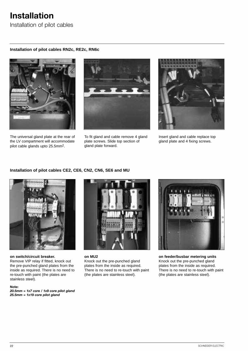
Installation of pilot cables RN2c, RE2c, RN6c
The universal gland plate at the rear ofthe LV compartment will accommodatepilot cable glands upto 25.5mm2.
To fit gland and cable remove 4 glandplate screws. Slide top section ofgland plate forward.
Insert gland and cable replace topgland plate and 4 fixing screws.
Installation of pilot cables CE2, CE6, CN2, CN6, SE6 and MU
on switch/circuit breaker.Remove VIP relay if fitted, knock outthe pre-punched gland plates from theinside as required. There is no need tore-touch with paint (the plates arestainless steel).
Note:20.5mm = 1x7 core / 1x9 core pilot gland25.5mm = 1x19 core pilot gland
on MU2Knock out the pre-punched glandplates from the inside as required.There is no need to re-touch with paint(the plates are stainless steel).
on feeder/busbar metering unitsKnock out the pre-punched glandplates from the inside as required.There is no need to re-touch with paint(the plates are stainless steel).
23SCHNEIDER ELECTRIC
InstallationRemoval of VIP relay
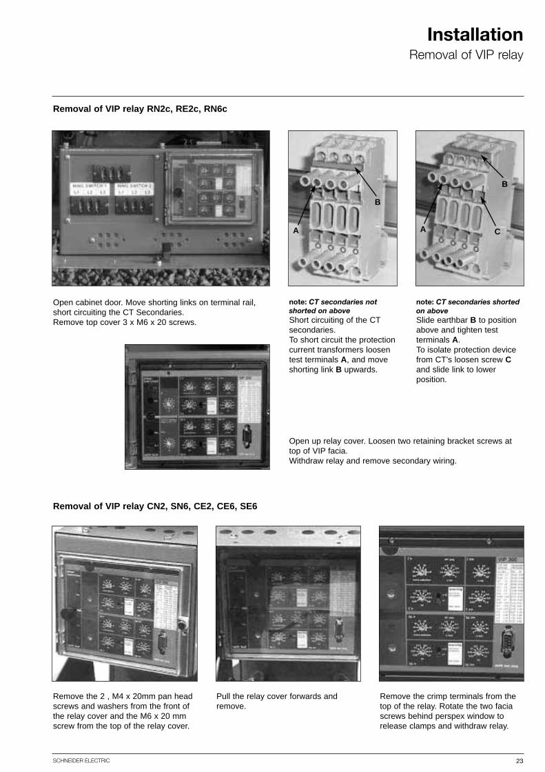
Removal of VIP relay RN2c, RE2c, RN6c
Open cabinet door. Move shorting links on terminal rail,short circuiting the CT Secondaries.Remove top cover 3 x M6 x 20 screws.
note: CT secondaries notshorted on aboveShort circuiting of the CTsecondaries.To short circuit the protectioncurrent transformers loosentest terminals A, and moveshorting link B upwards.
note: CT secondaries shortedon aboveSlide earthbar B to positionabove and tighten test terminals A.To isolate protection devicefrom CT’s loosen screw Cand slide link to lower position.
Open up relay cover. Loosen two retaining bracket screws attop of VIP facia.Withdraw relay and remove secondary wiring.
A
B
B
A C
Removal of VIP relay CN2, SN6, CE2, CE6, SE6
Remove the crimp terminals from thetop of the relay. Rotate the two faciascrews behind perspex window torelease clamps and withdraw relay.
Pull the relay cover forwards andremove.
Remove the 2 , M4 x 20mm pan headscrews and washers from the front ofthe relay cover and the M6 x 20 mmscrew from the top of the relay cover.
24 SCHNEIDER ELECTRIC
Accessing VT’s
Disconnection of solid link VT
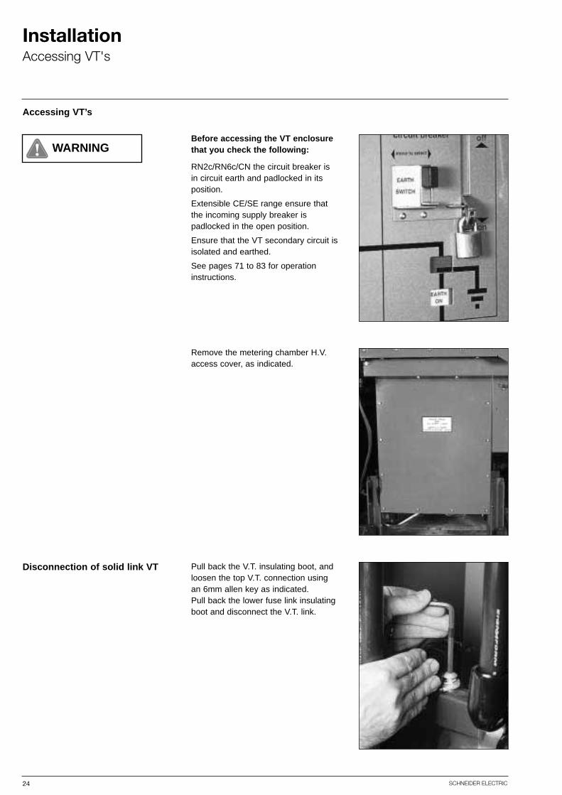
Before accessing the VT enclosurethat you check the following:
RN2c/RN6c/CN the circuit breaker isin circuit earth and padlocked in itsposition.
Extensible CE/SE range ensure thatthe incoming supply breaker is padlocked in the open position.
Ensure that the VT secondary circuit isisolated and earthed.
See pages 71 to 83 for operationinstructions.
Remove the metering chamber H.V.access cover, as indicated.
Pull back the V.T. insulating boot, andloosen the top V.T. connection usingan 6mm allen key as indicated.Pull back the lower fuse link insulatingboot and disconnect the V.T. link.
InstallationAccessing VT's
WARNING

25SCHNEIDER ELECTRIC
InstallationEarth fault flow indicator
Earth fault flow indicator
Hand or self reset earth fault flow indicators can be fitted.Please refer to manufacturers instructions.
For C.T.'s mounted inside the cablebox, gland insulation is not required.For C.T.'s fitted outside the cable boxgland insulation must be fitted.
Split core C.T.'s can be installed afterthe main cable has been made off outside the cable box. Howeverplease note gland insulation must befitted if mounted outside the cable box.Installation instructions for the unitsare supplied with the ancillary kits.
26 SCHNEIDER ELECTRIC
InstallationActuators
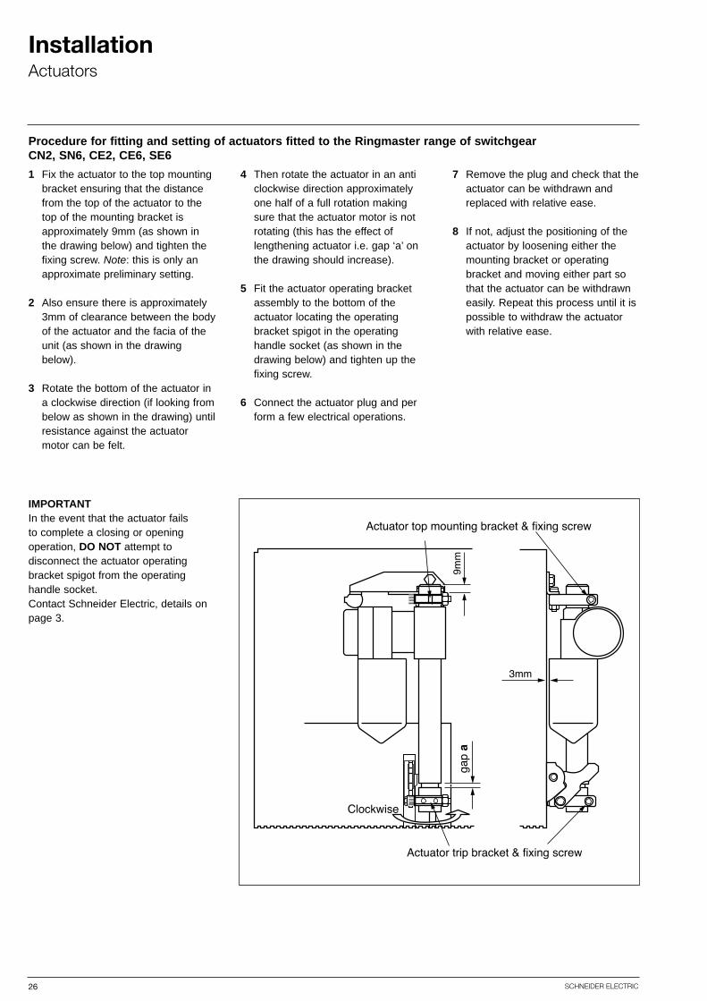
Procedure for fitting and setting of actuators fitted to the Ringmaster range of switchgearCN2, SN6, CE2, CE6, SE6
1 Fix the actuator to the top mounting bracket ensuring that the distance from the top of the actuator to the top of the mounting bracket is approximately 9mm (as shown in the drawing below) and tighten the fixing screw. Note: this is only an approximate preliminary setting.
2 Also ensure there is approximately 3mm of clearance between the body of the actuator and the facia of the unit (as shown in the drawing below).
3 Rotate the bottom of the actuator in a clockwise direction (if looking from below as shown in the drawing) until resistance against the actuator motor can be felt.
4 Then rotate the actuator in an anticlockwise direction approximately one half of a full rotation making sure that the actuator motor is not rotating (this has the effect of lengthening actuator i.e. gap ‘a’ on the drawing should increase).
5 Fit the actuator operating bracket assembly to the bottom of the actuator locating the operating bracket spigot in the operating handle socket (as shown in the drawing below) and tighten up the fixing screw.
6 Connect the actuator plug and perform a few electrical operations.
7 Remove the plug and check that the actuator can be withdrawn and replaced with relative ease.
8 If not, adjust the positioning of the actuator by loosening either the mounting bracket or operating bracket and moving either part so that the actuator can be withdrawn easily. Repeat this process until it is possible to withdraw the actuator with relative ease.
IMPORTANTIn the event that the actuator failsto complete a closing or openingoperation, DO NOT attempt todisconnect the actuator operatingbracket spigot from the operatinghandle socket.Contact Schneider Electric, details onpage 3.

27SCHNEIDER ELECTRIC
InstallationAccessories
Accessories
Accessories will be despatched either:■ Fitted to the unit within the works, i.e. too bulky or need testing prior to despatch■ Loose boxed for assembly on site
Anti-vandal measuresPadlock points are provided to prevent un-authorised access to the unit, padlockscan be supplied with the unit if required at the time of enquiry or order.
Available accessories are detailed in the Ringmaster selection guide Ref: MGMV 5337.Accessories will be detailed with individual confirmation orders.
28 SCHNEIDER ELECTRIC
InstallationFitting RE2c to Ringmaster range
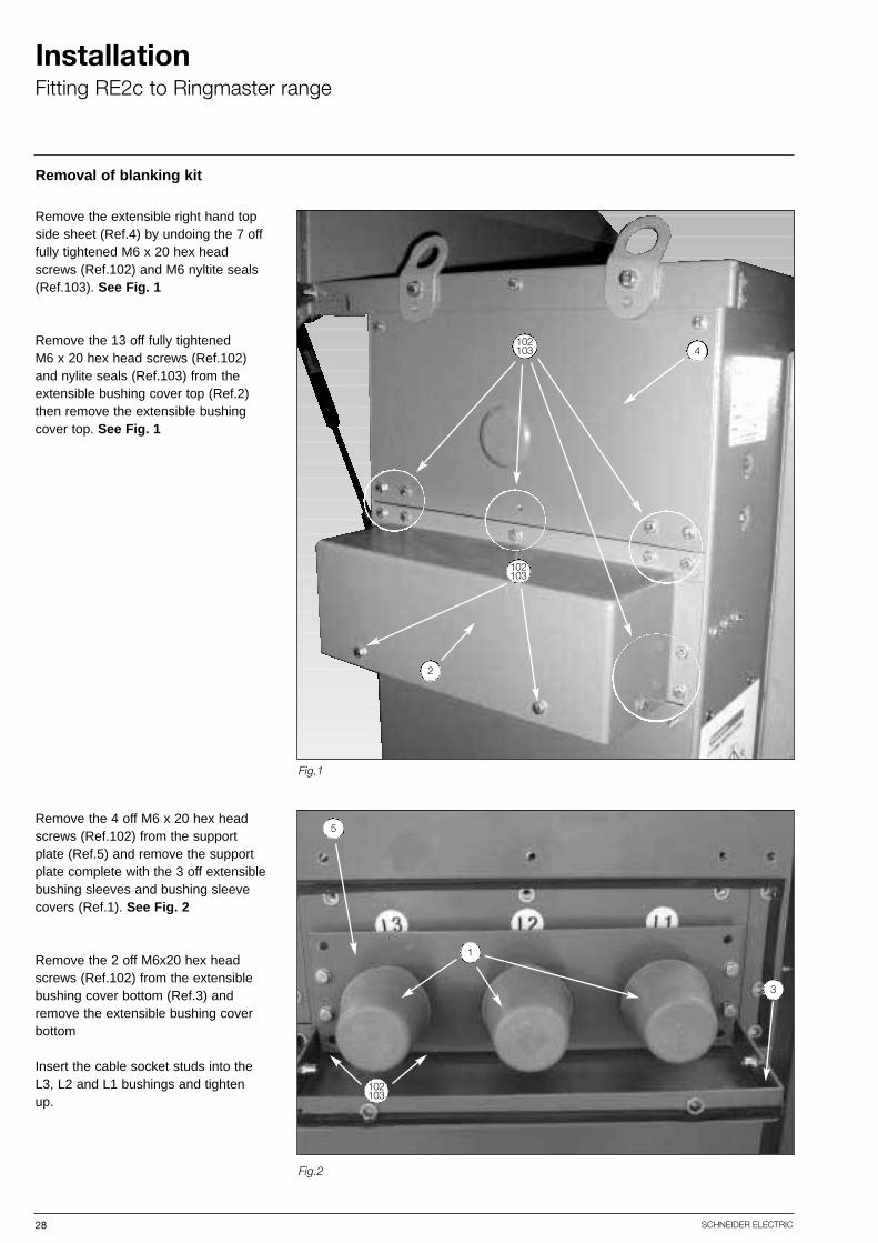
Removal of blanking kit
Fig.1
Fig.2
Remove the extensible right hand topside sheet (Ref.4) by undoing the 7 offfully tightened M6 x 20 hex headscrews (Ref.102) and M6 nyltite seals(Ref.103). See Fig. 1
Remove the 13 off fully tightened M6 x 20 hex head screws (Ref.102)and nylite seals (Ref.103) from theextensible bushing cover top (Ref.2)then remove the extensible bushingcover top. See Fig. 1
Remove the 4 off M6 x 20 hex headscrews (Ref.102) from the supportplate (Ref.5) and remove the supportplate complete with the 3 off extensiblebushing sleeves and bushing sleevecovers (Ref.1). See Fig. 2
Remove the 2 off M6x20 hex headscrews (Ref.102) from the extensiblebushing cover bottom (Ref.3) andremove the extensible bushing coverbottom
Insert the cable socket studs into theL3, L2 and L1 bushings and tightenup.
5
3
1
102103
102103
4
2
102103

29SCHNEIDER ELECTRIC
InstallationFitting RE2c to Ringmaster range
Transition plate to RE2c unit
Disconnect circlip and pivot pinassembly (Ref.A) retaining 2 off gasstrut (Ref.B) to fascia. See Fig. 3
Loosen off hardware at the main doorhinge (Ref.C) and slide out the 2 offmain door hinge pivots (Ref.D) whichretain the main door. See Fig. 4
NOTE: This door is heavy! Caremust be taken when removing it.
Remove the M8 & M6 (Ref.E) hardware retaining the lid in positionand place lid to one side. See Fig. 5
Fig.3
Fig.4
Fig.5
A
B
C
D
E
CAUTION
30 SCHNEIDER ELECTRIC
InstallationFitting RE2c to Ringmaster range
Transition plate to RE2c unit
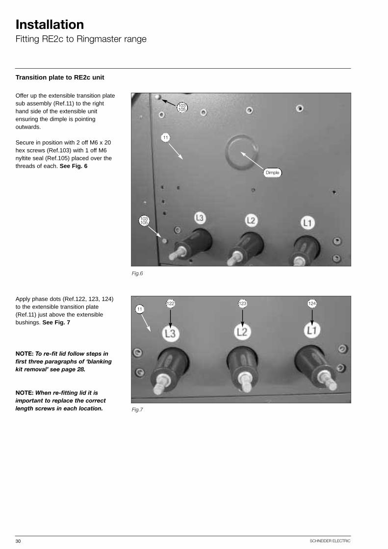
Offer up the extensible transition platesub assembly (Ref.11) to the righthand side of the extensible unit ensuring the dimple is pointing outwards.
Secure in position with 2 off M6 x 20hex screws (Ref.103) with 1 off M6nyltite seal (Ref.105) placed over thethreads of each. See Fig. 6
Apply phase dots (Ref.122, 123, 124)to the extensible transition plate(Ref.11) just above the extensiblebushings. See Fig. 7
NOTE: To re-fit lid follow steps infirst three paragraphs of ‘blankingkit removal’ see page 28.
NOTE: When re-fitting lid it isimportant to replace the correctlength screws in each location.
Fig.6
Fig.7
122 123 12411
103105
11
Dimple
103105
31SCHNEIDER ELECTRIC
InstallationFitting RE2c to Ringmaster range
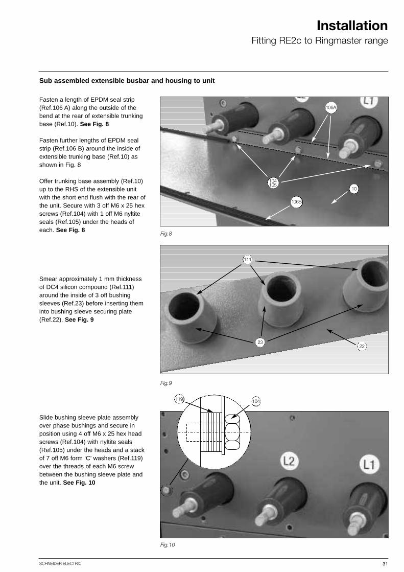
Sub assembled extensible busbar and housing to unit
Fasten a length of EPDM seal strip(Ref.106 A) along the outside of thebend at the rear of extensible trunkingbase (Ref.10). See Fig. 8
Fasten further lengths of EPDM sealstrip (Ref.106 B) around the inside ofextensible trunking base (Ref.10) asshown in Fig. 8
Offer trunking base assembly (Ref.10)up to the RHS of the extensible unitwith the short end flush with the rear ofthe unit. Secure with 3 off M6 x 25 hexscrews (Ref.104) with 1 off M6 nyltiteseals (Ref.105) under the heads ofeach. See Fig. 8
Smear approximately 1 mm thicknessof DC4 silicon compound (Ref.111)around the inside of 3 off bushing sleeves (Ref.23) before inserting theminto bushing sleeve securing plate(Ref.22). See Fig. 9
Slide bushing sleeve plate assemblyover phase bushings and secure inposition using 4 off M6 x 25 hex headscrews (Ref.104) with nyltite seals(Ref.105) under the heads and a stackof 7 off M6 form ‘C’ washers (Ref.119)over the threads of each M6 screwbetween the bushing sleeve plate andthe unit. See Fig. 10
Fig.8
Fig.9
Fig.10
104119
104105
10
106A
106B
111
2322

32 SCHNEIDER ELECTRIC
InstallationFitting RE2c to Ringmaster range
Transition plate and lid sub assembly
Push 17 off M6 hexagonal inserts(Ref.101) through the hexagonal holesaround the outside edge of the extensible left hand side sheet(Ref.14) ensuring all Inserts are facinginwards.
Secure all inserts in position using thecorrect insert tool. See Fig. 11
Fasten lengths of EPDM seal strip(Ref.106) around extensible left handside Sheet (Ref.14) as shown in Fig. 11.
Fasten lengths of EPDM seal strip(Ref.106) around the bend of theextensible trunking lid (Ref.12) asshown in Fig.12
Lay sub assembled extensible lefthand side sheet (Ref.14) on one side.Offer sub assembled extensible trunking lid (Ref.12) so the bend isflush with the side sheet. See Fig.12
Secure using 7 off M6 x 20 hex Hdscrews (Ref.103) together with 1 offM6 nyltite seal (Ref.105) under theheads of each.
Fig.11
Fig.12
101
101
14
106
106
14
12
103105
106

33SCHNEIDER ELECTRIC
InstallationFitting RE2c to Ringmaster range
Transition plate and lid sub assembly
Offer up trunking light hand side sheetand trunking lid sub assembly to theside of the extensible unit with theshort side flush with the rear of theunit. See Fig. 13
Secure trunking left hand side sheet(Ref.14) and lid (Ref.12) sub assemblyto the transition plate (Ref.11) using 9off M6 x 25 hex screws (Ref.104)together with 1 off M6 nyltite seal(Ref.105) under the heads of each,fully tighten these screws. Fit theextensible trunking lid (Ref.12) usingthe "flanged" end, this is fitted with; 5 off M6 x 20 hex screws (Ref.103.)with a nylite seal (Ref.105) under thehead of each. Fully tighten thesescrews after fitting.
Secure trunking left hand side sheet(Ref.14) to the trunking base (Ref.10)using 2 off M6 x 20 hex screws(Ref.103) together with 1 off M6 nyltiteseal (Ref.105) under the heads ofeach, fully tighten these screws.
Extensible busbar sub assembly
Place 1 off M10 form ‘A’ washer (Ref.121) over the threads of 1 off M10 x 30 hex screw (Ref.108) followed by 1 off RE2c conductoradapter (Ref.3).
Screw the above assembly into thethreaded end of the extensible L3 busbar (Ref.4)
Follow steps 6.1 and 6.2 for extensibleL2 busbar (Ref.5) and for extensibleL1 busbar (Ref.6).
See Fig 14 for the assembled components – each busbar shouldlook like this.
NOTE: Leave these assembliesloose and tighten up before starting‘sub assembled housing to unit’ seepage 35.
Fig.13
Fig.14
10
103105
103105
12
3
4
121
108
103105
34 SCHNEIDER ELECTRIC
InstallationFitting RE2c to Ringmaster range
Extensible busbar sub assembly
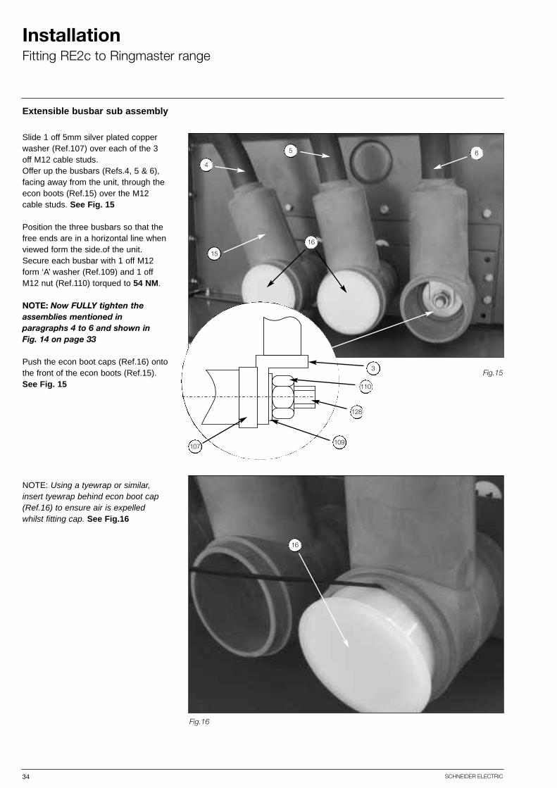
Slide 1 off 5mm silver plated copperwasher (Ref.107) over each of the 3off M12 cable studs. Offer up the busbars (Refs.4, 5 & 6),facing away from the unit, through theecon boots (Ref.15) over the M12cable studs. See Fig. 15
Position the three busbars so that thefree ends are in a horizontal line whenviewed form the side.of the unit.Secure each busbar with 1 off M12form ‘A’ washer (Ref.109) and 1 offM12 nut (Ref.110) torqued to 54 NM.
NOTE: Now FULLY tighten theassemblies mentioned in paragraphs 4 to 6 and shown in Fig. 14 on page 33
Push the econ boot caps (Ref.16) ontothe front of the econ boots (Ref.15).See Fig. 15
NOTE: Using a tyewrap or similar,insert tyewrap behind econ boot cap(Ref.16) to ensure air is expelled whilst fitting cap. See Fig.16
Fig.15
Fig.16
16
5
4
6
15
16
109
128
110
3
107
35SCHNEIDER ELECTRIC
InstallationFitting RE2c to Ringmaster range
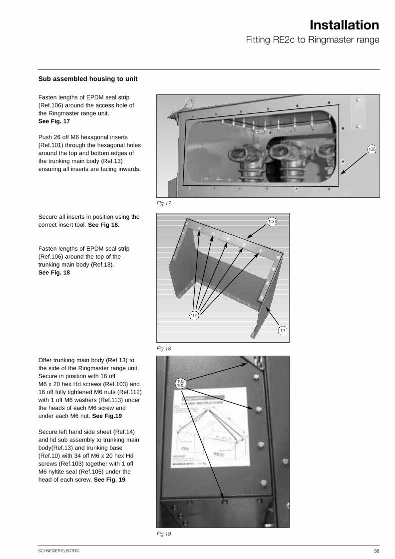
Sub assembled housing to unit
Fasten lengths of EPDM seal strip(Ref.106) around the access hole ofthe Ringmaster range unit. See Fig. 17
Push 26 off M6 hexagonal inserts(Ref.101) through the hexagonal holesaround the top and bottom edges ofthe trunking main body (Ref.13) ensuring all inserts are facing inwards.
Secure all inserts in position using thecorrect insert tool. See Fig 18.
Fasten lengths of EPDM seal strip(Ref.106) around the top of the trunking main body (Ref.13). See Fig. 18
Offer trunking main body (Ref.13) tothe side of the Ringmaster range unit.Secure in position with 16 off M6 x 20 hex Hd screws (Ref.103) and16 off fully tightened M6 nuts (Ref.112)with 1 off M6 washers (Ref.113) underthe heads of each M6 screw andunder each M6 nut. See Fig.19
Secure left hand side sheet (Ref.14)and lid sub assembly to trunking mainbody(Ref.13) and trunking base(Ref.10) with 34 off M6 x 20 hex Hdscrews (Ref.103) together with 1 offM6 nyltite seal (Ref.105) under thehead of each screw. See Fig. 19
Fig.17
Fig.19
Fig.18
106
106
13
101
103105
36 SCHNEIDER ELECTRIC
InstallationFitting RE2c to Ringmaster range
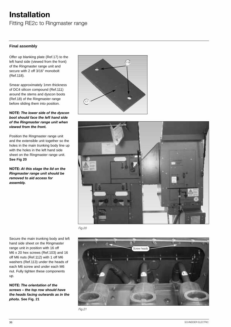
Final assembly
Offer up blanking plate (Ref.17) to theleft hand side (viewed from the front)of the Ringmaster range unit andsecure with 2 off 3/16” monobolt(Ref.118).
Smear approximately 1mm thicknessof DC4 silicon compound (Ref.111)around the stems and dyscon boots(Ref.18) of the Ringmaster rangebefore sliding them into position.
NOTE: The lower side of the dysconboot should face the left hand sideof the Ringmaster range unit whenviewed from the front.
Position the Ringmaster range unitand the extensible unit together so theholes in the main trunking body line upwith the holes in the left hand sidesheet on the Ringmaster range unit. See Fig 20
NOTE: At this stage the lid on theRingmaster range unit should beremoved to aid access for assembly.
Secure the main trunking body and lefthand side sheet on the Ringmasterrange unit in position with 16 off M6 x 20 hex screws (Ref.103) and 16off M6 nuts (Ref.112) with 1 off M6washers (Ref.113) under the heads ofeach M6 screw and under each M6nut. Fully tighten these componentsup.
NOTE: The orientation of thescrews – the top row should havethe heads facing outwards as in thephoto. See Fig. 21
Fig.21
Fig.20
118
17
Screw heads

37SCHNEIDER ELECTRIC
InstallationFitting RE2c to Ringmaster range
Earth bars to unit
Offer up the horizontal earth bar(Ref.20) to the rear of the extensibleunit. Secure the right hand side inposition behind the RE2c earth bar (Ref A) using 1 off M10 x 30 hex Hdscrew (Ref.127) with 1 off M10 form ‘A’washer (Ref.125) under the head anda further 1 off M10 form ‘A’ washer(Ref.125) under 1 off M10 hex full nut(Ref 126). See Fig. 22
Offer up the vertical earth bar (Ref.21) to the rear of the Ringmasterrange unit. Secure one end to theRingmaster range unit – in front of earth bar (Ref B) and the other endbehind the horizontal earth bar(Ref.20) using 1 off M10 x 30 hex Hdscrew (Ref.127) with 1 off M10 form ‘A’washer (Ref.125) under the head anda further 1 off M10 form ‘A’ washer(Ref.125) under 1 off M10 hex full nut(Ref.126). See Fig. 22
Fig.22
20
A
21
B
126
127
125

38 SCHNEIDER ELECTRIC
InstallationFitting RE2c to Ringmaster range
Fitment of front and rear transit braces
NOTE: These parts do NOT requirefitting if the unit is fitted to a plinthassembly!
The left hand ends of the rear andfront transit braces (Ref 8 and 9 asshown in Fig.23 ), are fitted to theinside faces of the "L" shaped struts (Ref C). Place an M8 form A washer(Ref.115) over 2 off M8 x 25 setscrews (Ref.130). Push each screw through the two "L" shaped brackets(Ref C) and the transit braces (Ref.8 and 9). Place another M8 FormA washer (Ref.115) over each screwthread and fit an M8 full nut (Ref.117)to each one – leave loose.
The right hand end (as shown in Fig.23) of the front transit brace (Ref.9) goes to the inside of the "U"shaped strut (Ref D). Put an M10 formA washer (Ref.121) over an M10 x 30hex head screw (Ref.127). Push thisthrough the front transit brace (Ref.9)and through the "U" shaped strut (Ref.D). Place an M10 form A washer(Ref.121) over the screw threads ofthe M10 x 30 hex head screw (Ref 127) and then fit an M10 full nut (Ref.126) - leave loose.
The rear brace (Ref.8) goes to theinside of the supporting foot (Ref.E).Place an M10 form A washer (Ref.125)over an M10 x 30 hex head screw(Ref.127). Push the screw with thewasher on through the support foot(Ref.E) and through the rear transitbrace (Ref.8). Place a 1 off M10 formA washer (Ref.125) over the thread ofthe screw and fit an M10 full nut(Ref.126)
Once all the above is complete fullytighten all the M10 and M8 hardwarementioned above. See Fig. 23 for thecompleted assembly.
Fig.23
8
E
C
D
9

39SCHNEIDER ELECTRIC
InstallationFitting RE2c to Ringmaster range
Ducting, HV and discharge testing of the units
Prior to carrying out the electricaltests the operator should completethe following:-
Secure all 3 off busbars to the stems(Ref.D) of the Ringmaster range unitusing 1 off M12 x 40 hex head screw(Ref.114) with the M12 flat washer(Ref.109) and 1 off busbar spacer(Ref.120) under each of the heads.Tighten the 3 off M12 x 40 hex headset screws (Ref.114) To 54 Nm with acalibrated torque wrench.
Slide the 3 off extensible conductorCap up the busbars and locate in position in the rear of the boots. Thesecaps are not visible in Fig 24 and arepart of the bought in, L3, L2 and L1sub assemblies.
Push dyscon dust caps (Ref.19) in thefront and top of the dyscon boots(Ref.18). See Fig. 24
At this point perform the three following tests:
■ High voltage partial discharge test■ High voltage frequency test■ Resistance test
NOTE: For transportation purposeson completion of the above theRingmaster range side of the busbar assembly must be un-torqued as it is to be fullytorqued up when in position on site.
Fig.24
19
18
D
109
120
4A
114

40 SCHNEIDER ELECTRIC
InstallationFitting RE2c to Ringmaster range
Securing of busbars and fitment of blanking plate
Fit the blanking plate (Ref.25) to theunit as shown in Fig. 25. This is fittedusing 10 off M6 x 20 screws with anyltite seal (Ref.105) under the headof each screw Insert these through theblanking plate (Ref.25) and the unit(Ref.A) and then fit an M6 form Awasher (Ref.113) followed by an M6full nut (Ref.112) fully tighten these up.See Fig. 25
Refit the previously removed lid to theRingmaster range unit plus lid edgestrips.(Ref.131) A lifting Lug willrequire fitting to the left hand side ofthe unit when viewed from the rear. Tofit the lid use; 12 off M6 x 20 screws(Ref.103) with an M6 nylite seal (Ref.105) under the head of each ofeach screw. These are followed by; 22 off M6 x 25hex head screws (Ref.104) with a andnylite seal (Ref.105) under the head ofeach. These 22 screws hold on the lidedge strips which are fitted using tessamol to make them weather tight.All the above hardware should now befully tightened up.
Fig.25
25

41SCHNEIDER ELECTRIC
InstallationFitting RE2c to Ringmaster range
Securing of busbars and fitment of blanking plate
Offer up RE2C - CE2/6 lid stiffeningplate (Ref.7) to the underside of therear of the Ringmaster range lid.Secure in position using 2 off M8 x 40screws (Ref.116) with 1 off M8 SSform ‘A’ washer under the head ofeach.Push the left hand screw (asviewed from the rear of the units as inthe figure left) through the lifting lug(Ref.D), through the lid edge strip(Ref.117) through the lid and throughthe lid stiffing plate (Ref.7) of the unit.
Next slide a further 1 off M8 form ‘A’washer (Ref.115) over the thread andfollowed by 2 off M8 hex full nuts(Ref.117) fully tighten the first nut andthen lock the second nut against eachthe first.
The right hand side is the sameassembly as the left with the exceptionthat the lifting lug (Ref.D) is not fitted.See Fig. 26
Fig.26
7
131D
131
116117
116117
Left hand viewed from rear of unitRight hand viewed from rear of unit

NOTE: This procedure only applieswhen the unit is on site.
When unit is in position on site removedyscon boot caps (Ref.19) from thetop of the dyscon boots (Ref.18). See Fig. 27
Fully secure each busbar assembly by torquing the M12 x 40 hex head set screw inside the dyscon boots to54Nm. See Fig. 27
Replace dyscon boot caps (Ref.19) inthe top of the dyscon boots (Ref.18).
Finally carry out ductor tests to the following ratings:
42 SCHNEIDER ELECTRIC
InstallationFitting RE2c to Ringmaster range
Final torque of busbars
Fig.27
Phase Resistance(micro ohms)
L1 196L2 198L3 200
19
18
114
120
4
A
109

43SCHNEIDER ELECTRIC
ProtectionTime fuse link
Protection systems
Time fuse link (TFL) protectionsummary
TFL selection
Recommended Time fuse Link (TFL) settings to ESI 12 - 6
All circuit breakers can be fitted with various forms of protection system -
1. VIP self powered IDMT protection - refer to VIP user guidesVIP 30 - provides protection against phase-to-phase faultsVIP 35 - provides protection against phase-to-phase faults and earth faultsVIP 300 - three phase overcurrent and earth fault protection
2. Time fuse link (TFL) protection system to EA 41-26 (time fuse links to EA 12-6).
Time fuse link protection provides a cost effective way of protecting a transformerof 1600kVA or less. It is a recognised method of protection and the fuses are covered by EA 12-6 (1973). The arrangements in the Ringmaster range is of 2 phase overcurrent and earth fault.
Schneider Electric recommend TFL sizes in accordance with the table below.
The table also includes our recommendations for the maximum LV fuse size toensure discrimination. Note that the size of this fuse is less than the full load current of the transformer, however, it would normally be expected to have a number of LV fuses fed from the LV side of the transformer.
Important note: Please ensure TFL fuses are fitted prior to energising the equipment.
3.3 10A - - - - - - TFL
(kV) 200 315 500 800 1000 1250 1600
150A - - - - - - LV fuse
6.6 5A 10A 15A - - - - TFL
150A 250A 400A - - - - LV fuse
11 3A 5A 10A 15A -
560A -
15A -
560A -
- -
- -
12.5A 15A
560A 560A
7.5A 10A 12.5A 15A
630A 630A
12.5A 15A
630A 630A
560A 630A
7.5A 10A
560A 630A
400A
10A
400A
15A
400A
7.5A
400A
- - TFL
200A 300A - - LV fuse
13.8 3A 5A - - TFL
200A 300A - - LV fuse
3.3 5A 10A - - TFL
150A 250A - - LV fuse
6.6 - 5A - - TFL
- 250A - - LV fuse
11 - - 5A TFL
- - 400A LV fuse
13.8 - - 5A TFL
- - 400A LV fuse
CT ratio = 50/5
voltage transformer rated power (kVA)
earth fault setting = 25A
(instantaneous trip)
CT ratio = 100/5
earth fault setting = 30A
(instantaneous trip)
WARNING
TLF protection will not work correctlyunless the recommended fuses are fitted.
44 SCHNEIDER ELECTRIC
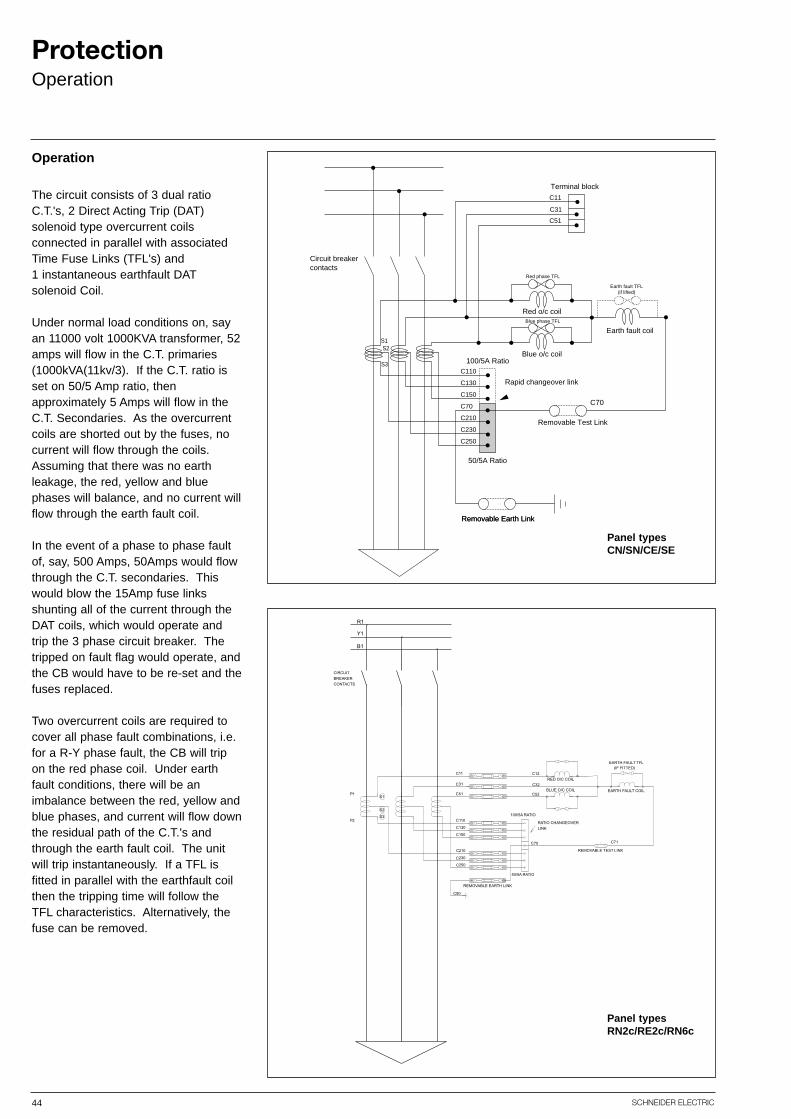
ProtectionOperation
The circuit consists of 3 dual ratioC.T.'s, 2 Direct Acting Trip (DAT) solenoid type overcurrent coils connected in parallel with associatedTime Fuse Links (TFL's) and 1 instantaneous earthfault DATsolenoid Coil.
Under normal load conditions on, sayan 11000 volt 1000KVA transformer, 52amps will flow in the C.T. primaries(1000kVA(11kv/3). If the C.T. ratio isset on 50/5 Amp ratio, then approximately 5 Amps will flow in theC.T. Secondaries. As the overcurrentcoils are shorted out by the fuses, nocurrent will flow through the coils.Assuming that there was no earthleakage, the red, yellow and blue phases will balance, and no current willflow through the earth fault coil.
In the event of a phase to phase faultof, say, 500 Amps, 50Amps would flowthrough the C.T. secondaries. Thiswould blow the 15Amp fuse links shunting all of the current through theDAT coils, which would operate and trip the 3 phase circuit breaker. Thetripped on fault flag would operate, andthe CB would have to be re-set and thefuses replaced.
Two overcurrent coils are required tocover all phase fault combinations, i.e.for a R-Y phase fault, the CB will trip on the red phase coil. Under earth fault conditions, there will be an imbalance between the red, yellow andblue phases, and current will flow downthe residual path of the C.T.'s andthrough the earth fault coil. The unitwill trip instantaneously. If a TFL is fitted in parallel with the earthfault coilthen the tripping time will follow the TFL characteristics. Alternatively, thefuse can be removed.
Operation
Removable Earth Link
Circuit breakercontacts
Removable Earth Link
Removable Test Link
50/5A Ratio
C250
C230
C210
C70
C150
C130
C110
100/5A Ratio
Rapid changeover link
Blue o/c coilS3
S2S1
Earth fault coil
Red o/c coil
Red phase TFL
Blue phase TFL
Earth fault TFL(if lifted)
Terminal block
C11
C31
C51
C70
C90
250
230
210
BREAKERCONTACTS
CIRCUIT
150
130
110
50/5A RATIO
C71
REMOVABLE TEST LINK
BLUE O/C COIL
RED O/C COIL
100/5A RATIO
RATIO CHANGEOVERLINK
C52
C32
C12(IF FITTED)
EARTH FAULT COIL
EARTH FAULT TFL
REMOVABLE EARTH LINK
P
PS
S
S2
70
31
11
51
C
C
C
C
C
C
C
C
C
C
11
32
R1
Y1
B1
Panel types CN/SN/CE/SE
Panel types RN2c/RE2c/RN6c

45SCHNEIDER ELECTRIC
ProtectionOperation
Close-up of C.T. links. Replacing the time fuse links.
Dual ratio 100/50/5Amp C.T.'s are fitted as standard, to the Ring MainUnits and 200 Amp circuit breakerswith TFL protection. Selection of theappropriate C.T. ratio can be easilyachieved by moving the auxiliary linkin the pilot cable box. Note that the circuit must be off load when changingratios.
WARNINGCurrent transformers not in use
Current transformers (T200E and earth fault flow indicator) that are not going to beused during commissioning or during service, they must be shorted out otherwiseirreversible damage may occur to current transformers and/or the unit.
46 SCHNEIDER ELECTRIC
ProtectionVIP 300
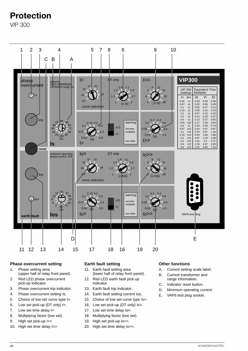
Phase overcurrent setting1. Phase setting area
(upper half of relay front panel).2. Red LED phase overcurrent
pick-up indicator.3. Phase overcurrent trip indicator.4. Phase overcurrent setting Is.5. Choice of low set curve type I>.6. Low set pick-up (DT only) I>.7. Low set time delay t>8. Multiplying factor (low set).9. High set pick-up I>>10. High set time delay t>>
Earth fault setting11. Earth fault setting area
(lower half of relay front panel).12. Red LED earth fault pick-up
indicator.13. Earth fault trip indicator.14. Earth fault setting current Ios.15. Choice of low set curve type Io>.16. Low set pick-up (DT only) Io>.17. Low set time delay to>.18. Multiplying factor (low set).19. High set pick-up Io>>.20. High set time delay to>>.
Other functionsA. Current setting scale label.B. Current transformer and
range information.C. Indicator reset button.D. Minimum operating current.E. VAP6 test plug socket.
VIP300
0.40.20.60.1
0.90.05
1.50.03
to>>(s)
129156
204
off3 (x Is)
0.20.150.30.1
0.40.07
0.60.05
0.40.20.60.1
0.90.05
1.50.03
t>>(s)
129156
204
off3 (x Ios)
2.11.82.41.5
2.71.2
31 (x Ios)
0.20.150.30.1
0.40.07
0.60.05
to>(s)
curve selection
DT onlyIo> Io>>
I>>
Is
4842 5636 64
30 7224 80
20 90100(A)
Ios
2416 3212 40
8 504 60
2 7080(A)
I>
I>
trip
reset
trip
Io>
earth fault
x10
sensors:200/1 4509996A0VIP300LH range: x2
minimum operatingphase current: 20A
phaseovercurrent
x1
EIVISI
offRI
DT
(s)
2.11.82.41.5
2.71.2
31 (x Is)
x10
x1
VAP6 test plug
EIVISI
offRI
DT
DT only
curve selection
t>
0.050.070.10.150.20.30.40.050.60.070.10.150.20.30.40.6
x1x1x1x1x1x1x1x10x1x10x10x10x10x10x10x10
0.020.020.030.050.070.100.130.170.200.240.340.500.671.011.352.02
0.030.050.070.100.130.200.270.330.400.470.671.001.332.02.674.00
0.060.090.120.190.250.370.500.620.740.871.241.862.483.714.957.43
t> to> SI VI EI
VIP 300Settings
Equivalent Time Multiplier
warning
not timemultiplier
see table
warning
not timemultiplier
see table
11 12 13 14
D
15 17 18 16 19 20
E
1 2 3
C B A
4 5 6 9 107 8
47SCHNEIDER ELECTRIC
ProtectionVIP 300
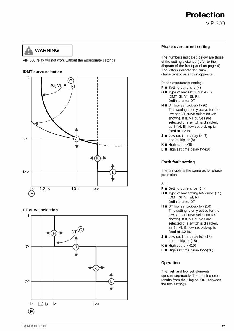
Phase overcurrent setting
The numbers indicated below are thoseof the setting switches (refer to the diagram of the front panel on page 4)The letters indicate the curve characteristic as shown opposite.
Phase overcurrent setting:F ■ Setting current Is (4)G ■ Type of low set I> curve (5)
IDMT: SI, VI, EI, RI.Definite time: DT
H ■ DT low set pick-up I> (6)This setting is only active for the low set DT curve selection (as shown). If IDMT curves are selected this switch is disabled, as SI,VI, EI, low set pick-up is fixed at 1.2 Is.
J ■ Low set time delay t> (7) and multiplier (8)
K ■ High set I>>(9)L ■ High set time delay t>>(10)
Earth fault setting
The principle is the same as for phaseprotection.
Set:F ■ Setting current Ios (14)G ■ Type of low setting Io> curve (15)
IDMT: SI, VI, EI, RIDefinite time: DT
H ■ DT low set pick-up Io> (16)This setting is only active for the low set DT curve selection (as shown). If IDMT curves are selected this switch is disabled, as SI, VI, EI low set pick-up is fixed at 1.2 Is.
J ■ Low set time delay to> (17) and multiplier (18)
K ■ High set Io>>(19)L ■ High set time delay to>>(20)
Operation
The high and low set elementsoperate separately. The tripping orderresults from the “ logical OR” betweenthe two settings.
Is
SI, VI, EI RIG
F
J
K
Lt>>
1.2 Is 10 Is I>>
t>
tIDMT curve selection
Is
DT G
Lt>>
t>
I>1.2 Is I>>
F
J
K
H
tDT curve selection
WARNING
VIP 300 relay will not work without the appropriate settings
48 SCHNEIDER ELECTRIC
ProtectionVIP 300
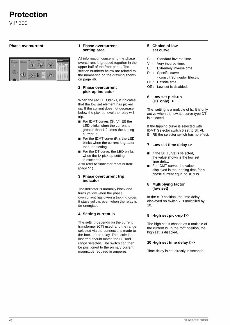
1 Phase overcurrent setting area
All information concerning the phaseovercurrent is grouped together in theupper half of the front panel. The section numbers below are related tothe numbering on the drawing shownon page 46.
2 Phase overcurrent pick-up indicator
When the red LED blinks, it indicatesthat the low set element has pickedup. If the current does not decreasebelow the pick-up level the relay willtrip.■ For IDMT curves (SI, VI, EI) the
LED blinks when the current is greater than 1.2 times the setting current Is.
■ For the IDMT curve (RI), the LED blinks when the current is greater than the setting.
■ For the DT curve, the LED blinks when the I> pick-up setting is exceeded.
Also refer to “indicator reset button”(page 51).
3 Phase overcurrent trip indicator
The indicator is normally black andturns yellow when the phase overcurrent has given a tripping order.It stays yellow, even when the relay isde-energised.
4 Setting current Is
The setting depends on the currenttransformer (CT) used, and the rangeselected via the connections made tothe back of the relay. The scale labelinserted should match the CT andrange selected. The switch can thenbe positioned to the primary current magnitude required in amperes.
Phase overcurrent 5 Choice of low set curve
SI : Standard inverse time.VI : Very inverse time.EI : Extremely inverse time.RI : Specific curve
- consult Schneider ElectricDT : Definite time.Off : Low set is disabled.
6 Low set pick-up (DT only) I>
The setting is a multiple of Is. It is onlyactive when the low set curve type DTis selected.
If the tripping curve is selected withIDMT (selector switch 5 set to SI, VI, EI, RI) the selector switch has no effect.
7 Low set time delay t>
■ If the DT curve is selected, the value shown is the low set time delay.
■ For IDMT curves the value displayed is the tripping time for a phase current equal to 10 x Is.
8 Multiplying factor (low set)
In the x10 position, the time delay displayed on switch 7 is multiplied by10.
9 High set pick-up I>>
The high set is chosen as a multiple ofthe current Is. In the “off” position, thehigh set is disabled.
10 High set time delay t>>
Time delay is set directly in seconds.
VIP300129
156
204
off3 (x Is)
0.20.150.30.1
0.40.07
0.60.05
0.40.20.60.1
0.90.05
1.50.03
t>>(s)
I>>
Is
4842 5636 64
30 7224 80
20 90100(A)
I>
I>
trip
reset
x10
sensors:200/1 4509996A0VIP300LH range: x2
phaseovercurrent
x1
EIVISI
offRI
DT
(s)
2.11.82.41.5
2.71.2
31 (x Is)
DT only
curve selection
t>
0.050.070.1
0.150.20.30.4
0.050.6
0.070.1
0.150.20.30.40.6
x1x1x1x1x1x1x1x10x1x10x10x10x10x10x10x10
0.020.020.030.050.070.100.130.170.200.240.340.500.671.011.352.02
0.030.050.070.100.130.200.270.330.400.470.671.001.332.0
2.674.00
0.060.090.120.190.250.370.500.620.740.871.241.862.483.714.957.43
t> to> SI VI EI
VIP 300Settings
Equivalent Time Multiplier
warning
not timemultiplier
see table
49SCHNEIDER ELECTRIC
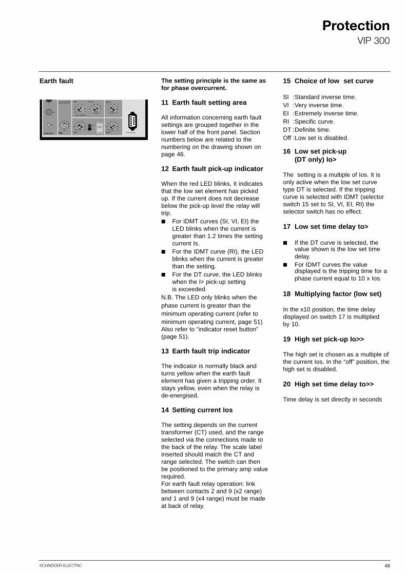
The setting principle is the same asfor phase overcurrent.
11 Earth fault setting area
All information concerning earth faultsettings are grouped together in thelower half of the front panel. Sectionnumbers below are related to the numbering on the drawing shown onpage 46.
12 Earth fault pick-up indicator
When the red LED blinks, It indicatesthat the low set element has pickedup. If the current does not decreasebelow the pick-up level the relay willtrip.■ For IDMT curves (SI, VI, EI) the
LED blinks when the current is greater than 1.2 times the setting current Is.
■ For the IDMT curve (RI), the LED blinks when the current is greater than the setting.
■ For the DT curve, the LED blinkswhen the l> pick-up setting is exceeded.
N.B. The LED only blinks when thephase current is greater than the minimum operating current (refer tominimum operating current, page 51) Also refer to “indicator reset button”(page 51).
13 Earth fault trip indicator
The indicator is normally black andturns yellow when the earth fault element has given a tripping order. Itstays yellow, even when the relay is de-energised.
14 Setting current Ios
The setting depends on the currenttransformer (CT) used, and the rangeselected via the connections made tothe back of the relay. The scale labelinserted should match the CT andrange selected. The switch can thenbe positioned to the primary amp valuerequired.For earth fault relay operation: linkbetween contacts 2 and 9 (x2 range)and 1 and 9 (x4 range) must be madeat back of relay.
Earth fault 15 Choice of low set curve
SI :Standard inverse time.VI :Very inverse time.EI :Extremely inverse time.RI :Specific curve.DT :Definite time.Off :Low set is disabled.
16 Low set pick-up (DT only) Io>
The setting is a multiple of Ios. It isonly active when the low set curvetype DT is selected. If the trippingcurve is selected with IDMT (selectorswitch 15 set to SI, VI, EI, RI) theselector switch has no effect.
17 Low set time delay to>
■ If the DT curve is selected, the value shown is the low set time delay.
■ For IDMT curves the value displayed is the tripping time for a phase current equal to 10 x Ios.
18 Multiplying factor (low set)
In the x10 position, the time delay displayed on switch 17 is multiplied by 10.
19 High set pick-up Io>>
The high set is chosen as a multiple ofthe current Ios. In the “off” position, thehigh set is disabled.
20 High set time delay to>>
Time delay is set directly in seconds
0.40.20.60.1
0.90.05
1.50.03
to>>(s)
129156
204
off3 (x Ios)
2.11.82.41.5
2.71.2
31 (x Ios)
0.20.150.30.1
0.40.07
0.60.05
to>(s)
curve selection
DT onlyIo> Io>>
Ios
2416 3212 40
8 504 60
2 7080(A)
reset
trip
Io>
earth fault
minimum operatingphase current: 20A
x10
x1
VAP6 test plug
EIVISI
offRI
DT
warning
not timemultiplier
see table
ProtectionVIP 300

50 SCHNEIDER ELECTRIC
ProtectionVIP 300
Other functions A. Setting scale label
■ The label indicates the range for the phase overcurrent and earthfault primary amp settings. It isinserted from the top, behind thetransparent part of the front panel.
■ The label is reversible and is printed with the x2 range setting currents on one side, and the x4 range setting currents on the other. The scale label when inserted should match the CT and terminal positions on the rear of the relay, for the range required.
Also refer to “testing and commissioning”.
B. CT and range indication
The CT and range are given on eachside of the setting scale label. The labelwill match the appropriate CT for theRingmaster panel type supplied. Thisinformation is hidden when the label isinserted.
Choice of setting scale label
■ Make sure that the information given on the top of the label matches:1 - The current transformer used:
200/1A, 400/1A or 800/1A2 - The range used.
x2 or x4
This information is hidden when thelabel is in position.
■ For help with the choice of range to select, refer to the application section.
Installation
■ Slide the setting scale into position behind the transparent part of the front face.
■ Make sure the label is pushed right into the bottom of the slot. To remove the label, use the hole in the top, if necessary with the help of the tip of a pencil or a screwdriver.
VIP 300LH range: x2
(A)
sensor200/1: 4509996A0
Is4842 56
36 6430 7224 80
20 90100
sensor200/1: 4509996A0
VIP 300LHrange: x4
Is9684 112
72 12860 14448 160
40 180200
minimum operatingphase current: 20A
Ios2416 32
12 408 504 60
2 7080
minimum operatingphase current: 40A
(A)
(A)
x 2 range
Reversible scale label for Ringmaster fitted with 200/1A CT’s
Ios4832 64
24 8016 1008 120
4 140160(A)
x 4 range
x 2 range x 4 range
Reversible scale label for Ringmaster fitted with 400/1A CT’s
VIP 300LH range: x2
(A)
sensor400/1: 451101200
Is9684 112
72 12860 14448 160
40 180200
sensor400/1: 451101200
VIP 300LHrange: x4
Is192168 224
144 256120 28896 320
80 360400
minimum operatingphase current: 40A
Ios4832 64
24 8016 1008 120
4 140160
minimum operatingphase current: 80A
(A)
(A)
Ios9664 128
48 16032 20016 240
8 280320(A)
VIP 300LH range: x2
(A)
sensor800/1: 4509169A0
Is192168 224
144 256120 28896 320
80 360400
sensor800/1: 4509169A0
VIP 300LHrange: x4
Is384336 448
288 512240 576192 640
160 720800
minimum operatingphase current: 80A
Ios9664 128
48 16032 20016 240
8 280320
minimum operatingphase current: 160A
Ios192128 256
96 32064 40032 480
16 560640
(A)
(A)
(A)
x 2 range x 4 range
Reversible scale label for Ringmaster fitted with 800/1A CT’s
51SCHNEIDER ELECTRIC
ProtectionVIP 300
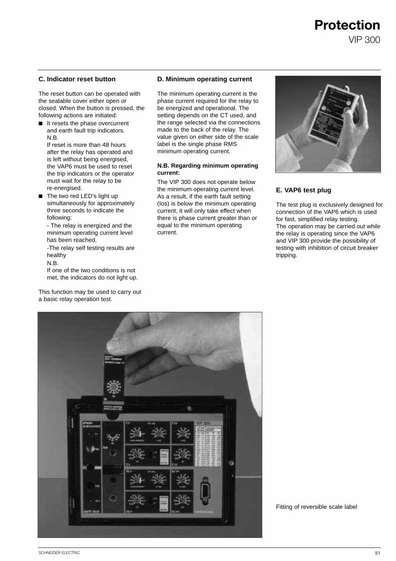
C. Indicator reset button
The reset button can be operated withthe sealable cover either open orclosed. When the button is pressed, thefollowing actions are initiated:■ It resets the phase overcurrent
and earth fault trip indicators. N.B. If reset is more than 48 hours after the relay has operated and is left without being energised, the VAP6 must be used to reset the trip indicators or the operator must wait for the relay to be re-energised.
■ The two red LED’s light up simultaneously for approximately three seconds to indicate the following:- The relay is energized and the minimum operating current level has been reached.-The relay self testing results are healthyN.B.If one of the two conditions is not met, the indicators do not light up.
This function may be used to carry outa basic relay operation test.
D. Minimum operating current
The minimum operating current is thephase current required for the relay tobe energized and operational. The setting depends on the CT used, andthe range selected via the connectionsmade to the back of the relay. Thevalue given on either side of the scalelabel is the single phase RMS minimum operating current.
N.B. Regarding minimum operatingcurrent:
The VIP 300 does not operate belowthe minimum operating current level.As a result, if the earth fault setting(Ios) is below the minimum operatingcurrent, it will only take effect whenthere is phase current greater than orequal to the minimum operating current.
E. VAP6 test plug
The test plug is exclusively designed forconnection of the VAP6 which is usedfor fast, simplified relay testing.The operation may be carried out whilethe relay is operating since the VAP6and VIP 300 provide the possibility oftesting with inhibition of circuit breakertripping.
Fitting of reversible scale label
52 SCHNEIDER ELECTRIC
ProtectionVAP6
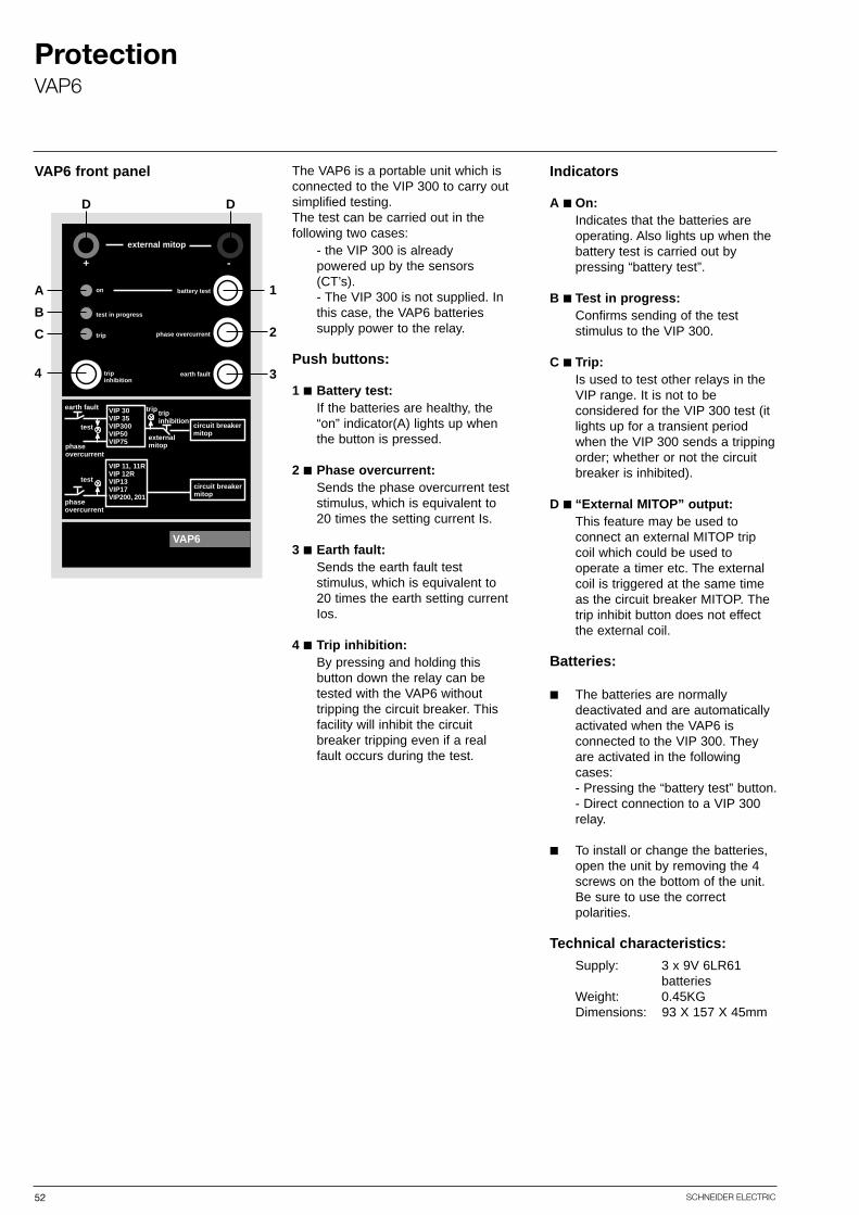
The VAP6 is a portable unit which isconnected to the VIP 300 to carry outsimplified testing.The test can be carried out in the following two cases:
- the VIP 300 is already powered up by the sensors (CT’s).- The VIP 300 is not supplied. In this case, the VAP6 batteries supply power to the relay.
Push buttons:
1 ■ Battery test:If the batteries are healthy, the “on” indicator(A) lights up when the button is pressed.
2 ■ Phase overcurrent:Sends the phase overcurrent test stimulus, which is equivalent to 20 times the setting current Is.
3 ■ Earth fault:Sends the earth fault test stimulus, which is equivalent to20 times the earth setting current Ios.
4 ■ Trip inhibition:By pressing and holding this button down the relay can be tested with the VAP6 without tripping the circuit breaker. This facility will inhibit the circuit breaker tripping even if a real fault occurs during the test.
VAP6 front panel Indicators
A ■ On:Indicates that the batteries are operating. Also lights up when the battery test is carried out by pressing “battery test”.
B ■ Test in progress:Confirms sending of the test stimulus to the VIP 300.
C ■ Trip:Is used to test other relays in the VIP range. It is not to be considered for the VIP 300 test (it lights up for a transient period when the VIP 300 sends a tripping order; whether or not the circuit breaker is inhibited).
D ■ “External MITOP” output:This feature may be used to connect an external MITOP trip coil which could be used to operate a timer etc. The external coil is triggered at the same time as the circuit breaker MITOP. The trip inhibit button does not effect the external coil.
Batteries:
■ The batteries are normally deactivated and are automatically activated when the VAP6 is connected to the VIP 300. They are activated in the following cases:- Pressing the “battery test” button.- Direct connection to a VIP 300relay.
■ To install or change the batteries,open the unit by removing the 4 screws on the bottom of the unit. Be sure to use the correct polarities.
Technical characteristics:
Supply: 3 x 9V 6LR61 batteries
Weight: 0.45KGDimensions: 93 X 157 X 45mm
I>
on
external mitop
VAP6
+ -
test in progress
trip
tripinhibition
earth fault
phase overcurrent
battery test
circuit breakermitop
circuit breakermitop
earth fault VIP 30VIP 35VIP300VIP50VIP75
VIP 11, 11RVIP 12RVIP13VIP17VIP200, 201
test
phaseovercurrent
test
phaseovercurrent
trip tripinhibition
externalmitop
A
B
C
D
4
D
1
2
3

53SCHNEIDER ELECTRIC
ProtectionVAP6
The test may be carried out with orwithout the relay energised by theRingmaster current transformers, andall the relay settings are effective.During the test, the relay remains operational and will give a trippingorder in the event of a fault, unless the“trip inhibit” button is pressed and helddown.
Connect the VAP6 to the “VAP6 testplug”. The VAP6 batteries are activatedand the “on” indicator lights up.
Press the “trip inhibition” button if thetest should be carried out without tripping the circuit breaker.Be sure to continue pressing the “trip inhibition” button throughout thetime it takes to send the stimulus.
The test consists of:- Initiation of the VIP 300 self monitoring and diagnostic routine.- Injecting a stimulus to stimulate a phase fault. - Check trippingThe VAP6 is supplied by batteries. Therefore the parts of the VIP 300 that run on ACcurrent are not checked using this method (input and supply circuits).
Press the “phase overcurrent” button tosend the test stimulus.
- Continue pressing the button throughout the duration of the stimulus. The stimulus represents about 20 times the setting current Is.-The VAP6 “test in progress” indicator lights up to confirm the sending of the stimulus to the VIP300 relay.- The red “I>” indicator of the VIP300 blinks during the time relay delay period.- Then the VIP 300 phase “trip” indicator turns yellow.- The circuit breaker trips if it is not inhibited.
N.B. If the “phase overcurrent” button isheld down after tripping, the VIP300starts the time delay/tripping cycleagain; this is normal operation. In that case:
- The VAP6 red “trip” indicator lights up for a transient period each time there is a trip.- Depending on the time delay setting, the VIP 300 red “I>” indicator may be off or blink rapidly and/or in an irregular manner.
Press “earth fault” to test the relaysoperation. The stimulus injected is equalto 20 times the setting current Ios. Usethe procedure as for the phase overcurrent test.
Disconnect the VAP6. In order to savebatteries, do not leave the VAP6 connected to the relay unnecessarily.

54 SCHNEIDER ELECTRIC
CommissioningChecks and tests
Commissioning
Physical checks
Functional checks
High voltage withstand test toIEC60694 and IEC62271-200.
All equipment is subject to stringent quality and operational checks prior todespatch. However it is the owners responsibility to ensure that commissioning tests have been completed to IEC60694. The following is a resumeof those tests.
Remove all packaging and transit labels from the equipment. Check the data platedetails against the specification. Check the operation of the switches/circuit breaker, test access and various interlocks.
Check confirmation of auxiliary switch contacts and remote indication in accordance with the schematic diagram.Confirm the phase relationship of the neon indicator sockets.Check the pick up voltage of auxiliary coils if fitted, a.c. coils should operatebetween 85% and 110% of the rated voltage, d.c. coils should operate between70% and110% of the rated voltage.
Note: All voltages should be applied instantaneously unless otherwise specified.
Connect the H.V. test set as shown in the diagrams an carry out the withstand tests in accordance with the following tables.
FRONT
RN2c
RN2c/RE2c/RN6c
CE2/CE6/SE6 or SN6/CN2
(enclosed in busbar chamber)
B1Y1R1
B2Y2R2 B3Y3R3
R1Y1B1
R2Y2B2
55SCHNEIDER ELECTRIC
CommissioningTests
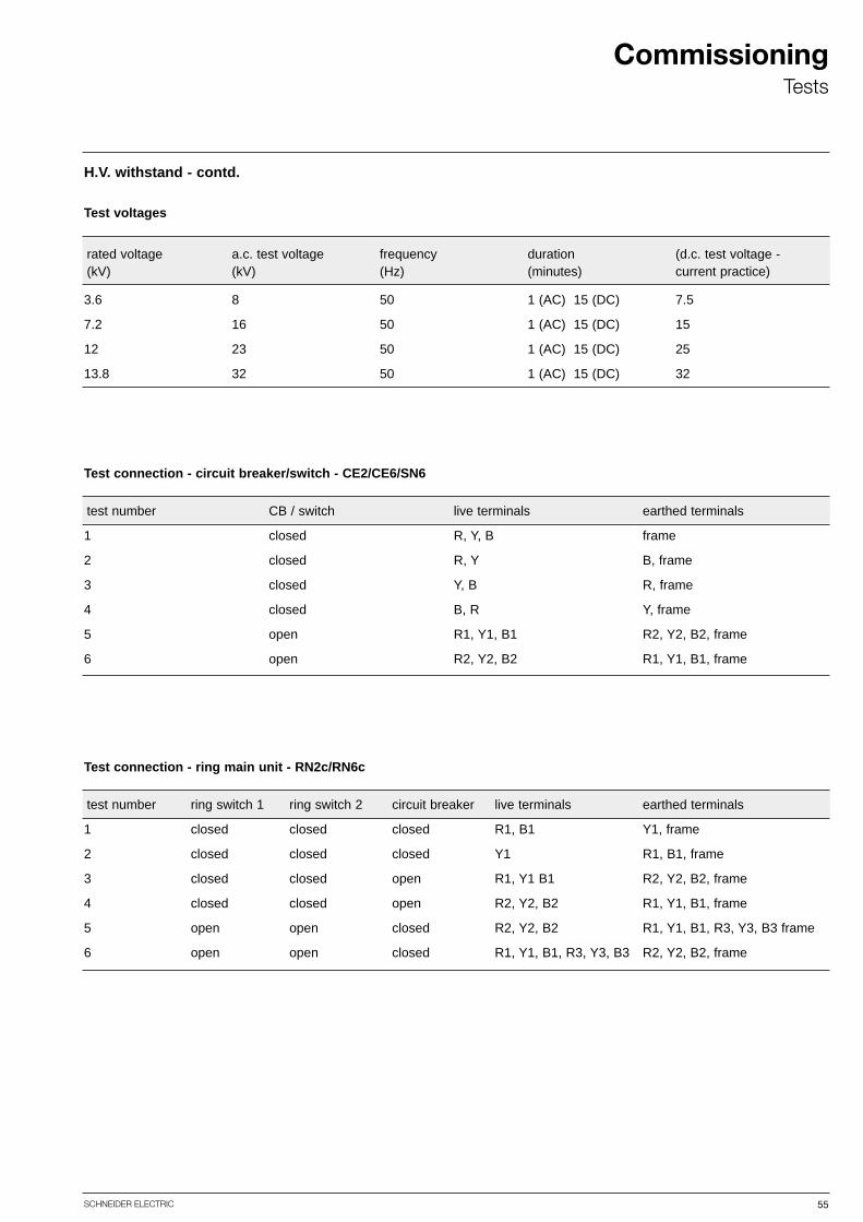
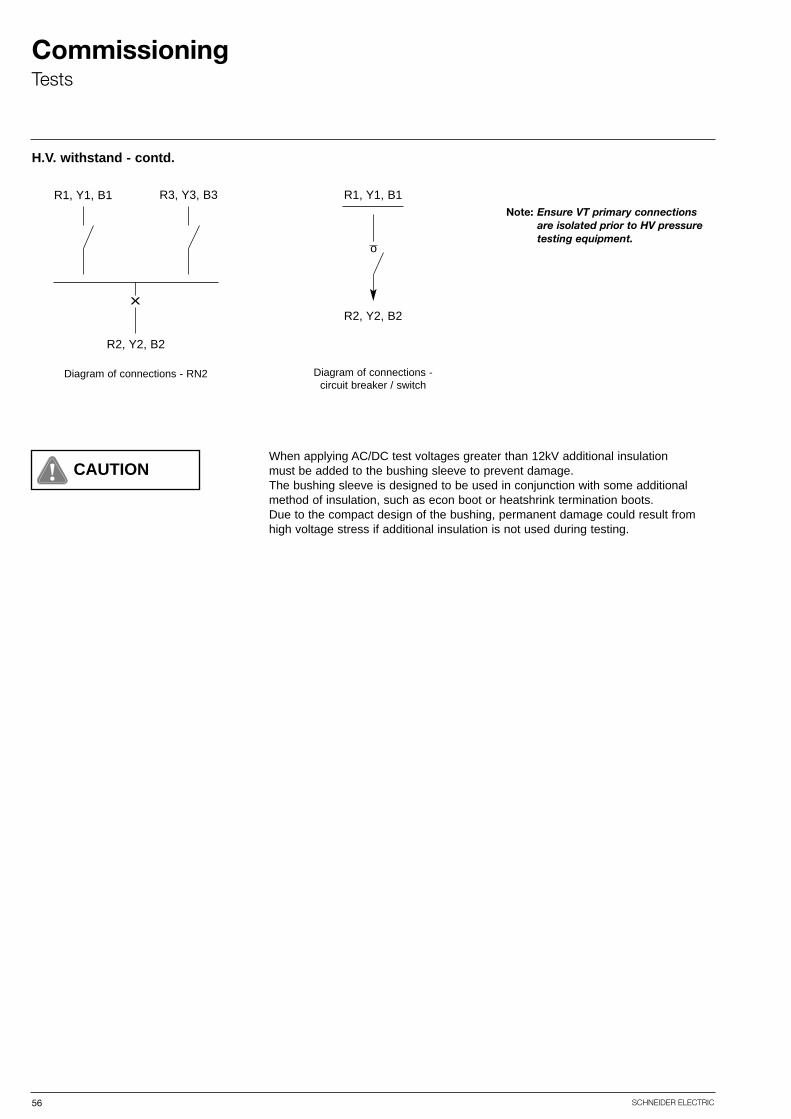
H.V. withstand - contd.
Test voltages
Test connection - circuit breaker/switch - CE2/CE6/SN6
3.6 8 50 1 (AC) 15 (DC) 7.5
7.2 16 50 1 (AC) 15 (DC) 15
12 23 50 1 (AC) 15 (DC) 25
13.8 32 50 1 (AC) 15 (DC) 32
test number
1
2
3
4
5
6
CB / switch
closed
closed
closed
closed
open
open
live terminals
R, Y, B
R, Y
Y, B
B, R
R1, Y1, B1
R2, Y2, B2
earthed terminals
frame
B, frame
R, frame
Y, frame
R2, Y2, B2, frame
R1, Y1, B1, frame
rated voltage(kV)
a.c. test voltage(kV)
frequency(Hz)
duration(minutes)
(d.c. test voltage - current practice)
Test connection - ring main unit - RN2c/RN6c
test number
1
2
3
4
5
6
ring switch 1 ring switch 2
closed closed closed
closed closed
closed open
closed open
open
open
closed
closed
closed
closed
closed
open
open
circuit breaker live terminals
R1, B1
Y1
R1, Y1 B1
R2, Y2, B2
R2, Y2, B2
R1, Y1, B1, R3, Y3, B3
earthed terminals
Y1, frame
R1, B1, frame
R2, Y2, B2, frame
R1, Y1, B1, frame
R1, Y1, B1, R3, Y3, B3 frame
R2, Y2, B2, frame
56 SCHNEIDER ELECTRIC
CommissioningTests
R1, Y1, B1
R2, Y2, B2
R3, Y3, B3
Diagram of connections - RN2
xR2, Y2, B2
R1, Y1, B1
Diagram of connections - circuit breaker / switch
o
Note: Ensure VT primary connections are isolated prior to HV pressure testing equipment.
When applying AC/DC test voltages greater than 12kV additional insulationmust be added to the bushing sleeve to prevent damage.The bushing sleeve is designed to be used in conjunction with some additionalmethod of insulation, such as econ boot or heatshrink termination boots.Due to the compact design of the bushing, permanent damage could result fromhigh voltage stress if additional insulation is not used during testing.
H.V. withstand - contd.
CAUTION
57SCHNEIDER ELECTRIC
CommissioningTests
Removable Earth Link
A
R1
Y1
B1
Circuit breakercontacts
50/100A a.c.
Selectphase
Removable Earth Link
0 - 5A
Removable Test Link
50/5A Ratio
C250
C230
C210
C70
C150
C130
C110
100/5A Ratio
Rapid changeover link
Blue o/c coilS3
S2S1
Earth fault coil
Red o/c coil
Red phase TFL
Blue phase TFL
Earth fault TFL(if lifted)
R2 Y2 B2
Selectphase
Terminal block
C11
C31
C51
Selectphase
C70
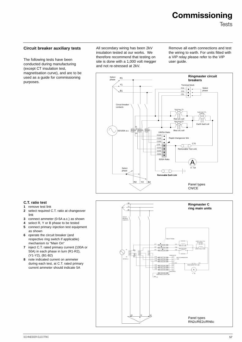
Circuit breaker auxiliary tests
C.T. ratio test1 remove test link2 select required C.T. ratio at changeover
link3 connect ammeter (0-5A a.c.) as shown 4 select R, Y or B phase to be tested 5 connect primary injection test equipment
as shown6 operate the circuit breaker (and
respective ring switch if applicable)mechanism to "Main On"
7 inject C.T. rated primary current (100A or50A) in each phase in turn (R1-R2), (Y1-Y2), (B1-B2)
8 note indicated current on ammeter during each test, at C.T. rated primary current ammeter should indicate 5A
All secondary wiring has been 2kVinsulation tested at our works. Wetherefore recommend that testing onsite is done with a 1,000 volt meggerand not re-stressed at 2kV.
The following tests have been conducted during manufacturing(except CT insulation test, magnetisation curve), and are to beused as a guide for commissioningpurposes.
Remove all earth connections and testthe wiring to earth. For units fitted witha VIP relay please refer to the VIPuser guide.
Ringmaster circuit breakers
Panel types CN/CE
Ringmaster Cring main units
Panel types RN2c/RE2c/RN6c
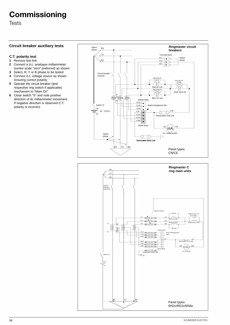
58 SCHNEIDER ELECTRIC
CommissioningTests
Ringmaster Cring main units
Ringmaster circuit breakers
Removable Earth Link
mA
R1
Y1
B1
Circuit breakercontacts
Switch 'S'
Selectphase
Removable Earth Link
d.c. milliammeter
Removable Test Link
50/5A Ratio
C250
C230
C210
C70
C150
C130
C110
100/5A Ratio
Rapid changeover link
Blue o/c coilS3
S2S1
Earth fault coil
Red o/c coil
Red phase TFL
Blue phase TFL
Earth fault TFL(if lifted)
R2 Y2 B2
Selectphase
Terminal block
C11
C31
C51
Selectphase
6V - 12Vd.c.+ve
-ve
+ve-ve
C70
Circuit breaker auxiliary tests
C.T. polarity test1 Remove test link2 Connect a d.c. analogue milliammeter
(centre scale "zero" preferred) as shown3 Select, R, Y or B phase to be tested4 Connect d.c. voltage source as shown
ensuring correct polarity5 Operate the circuit breaker (and
respective ring switch if applicable) mechanism to "Main On"
6 Close switch "S" and note positive direction of dc milliammeter movement. If negative direction is observed C.T.polarity is incorrect.
Panel types CN/CE
Panel types RN2c/RE2c/RN6c

59SCHNEIDER ELECTRIC
CommissioningTests
Removable Earth Link
mA
R1
Y1
B1
Circuit breakercontacts
Selectphase
Removable Earth Link
0 - 10mA a.c.
Removable Test Link
50/5A Ratio
C250
C230
C210
C70
C150
C130
C110
100/5A Ratio
Rapid changeover link
Blue o/c coilS3
S2S1
Earth fault coil
Red o/c coil
Temporary TFL Shorting Link
Earth fault TFL(if lifted)
R2 Y2 B2
Terminal block
C11
C31
C51
Three phaseshorting link(100A rated)
C70
50/100A a.c.
Temporary TFL Shorting Link
C.T. spill test1 Remove test link2 Select required C.T. ratio at changeover
link3 Connect 3 phase short circuiting link
(100A rated) at R1, Y1 and B1 connections
4 Replace R and B.T.F.L.'s for temporary shorting links as shown Note: a shorting link in parallel withthe earth fault coil is not required
5 Connect an a.c. milliammeter as shown 6 Select R-Y, Y-B or R-B phases to be
tested7 Connect primary current injection test
equipment as shown 8 Operate the circuit breaker (and
respective ring switch if applicable) mechanism to "Main On"
9 Inject C.T. rated primary current and note spill current indicated on ammeter
10 Spill current to be less than 10mAduring the test
11 Repeat for remaining pairs of phases (and C.T. ratio if required)
Ringmaster circuit breakers
Ringmaster Cring main units
Panel types CN/CE
Panel types RN2c/RE2c/RN6c

60 SCHNEIDER ELECTRIC
CommissioningTests
Ringmaster circuit breakers
Ringmaster Cring main units
Removable Earth Link
R1
Y1
B1
Circuit breakercontacts
Selectphase
Removable Earth Link
Removable Test Link
50/5A Ratio
C250
C230
C210
C70
C150
C130
C110
100/5A Ratio
Rapid changeover link
Blue o/c coilS3
S2S1
Earth fault coil
Red o/c coil
Temporary TFL Shorting Link
Earth fault TFL(if lifted)
R2 Y2 B2
Terminal block
C11
C31
C51
Three phaseshorting link(100A rated)
C70
50/100A a.c.
Temporary TFL Shorting Link
T.F.L. / D.A.T. overcurrent tests -primary current injection1 Ensure removable earth link is fitted2 Select required C.T. ratio at changeover
link3 Connect 3 phase short circuiting link
(100A rated) at R1, Y1 and B1 connections
4 Replace R and B.T.F.L.'s for temporary shorting links as shownNote: a shorting link in parallel withthe earth fault coil is not required
5 Select R-Y, Y-B or R-B phases to betested
6 Connect primary current injection test equipment as shown
7 Operate the circuit breaker (and respective ring switch if applicable) mechanism to "Main On"
8 Inject C.T. rated primary current and remove the T.F.L. shorting links in accordance with the table below ensuring the correct action results
9 Repeat for remaining parts of phases(and C.T. ratio if required)
10 Note - with both R & B T.F.L. shortinglinks in circuit, the circuit breaker shouldnot trip during overcurrent testsNote: ensure test current does notreduce signification due to circuit impedance changes during this test
R - YR - YY - BY - BR - BR - B
RBBRRB
BRRBBR
no triptrip
no triptriptriptrip
phasesundertest In cct Out cct
T.F.L shorting link circuitbreakeraction
Panel types CN/CE
Panel types RN2c/RE2c/RN6c
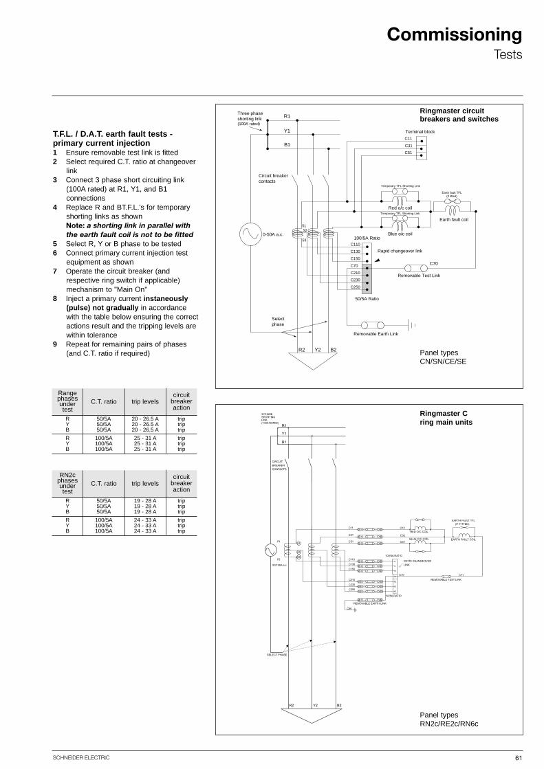
61SCHNEIDER ELECTRIC
CommissioningTests
R1
Y1
B1
Circuit breakercontacts
0-50A a.c.
Selectphase
Removable Earth Link
Removable Test Link
50/5A Ratio
C250
C230
C210
C70
C150
C130
C110
100/5A Ratio
Rapid changeover link
Blue o/c coilS3
S2S1
Earth fault coil
Red o/c coil
Temporary TFL Shorting Link
Earth fault TFL(if lifted)
R2 Y2 B2
Terminal block
C11
C31
C51
Three phaseshorting link(100A rated)
C70
Temporary TFL Shorting Link
T.F.L. / D.A.T. earth fault tests - primary current injection1 Ensure removable test link is fitted2 Select required C.T. ratio at changeover
link3 Connect 3 phase short circuiting link
(100A rated) at R1, Y1, and B1 connections
4 Replace R and BT.F.L.'s for temporary shorting links as shownNote: a shorting link in parallel withthe earth fault coil is not to be fitted
5 Select R, Y or B phase to be tested6 Connect primary current injection test
equipment as shown7 Operate the circuit breaker (and
respective ring switch if applicable) mechanism to "Main On"
8 Inject a primary current instaneously(pulse) not gradually in accordancewith the table below ensuring the correct actions result and the tripping levels arewithin tolerance
9 Repeat for remaining pairs of phases (and C.T. ratio if required)
RYB
RYB
50/5A50/5A50/5A
100/5A100/5A100/5A
20 - 26.5 A20 - 26.5 A20 - 26.5 A
25 - 31 A25 - 31 A25 - 31 A
triptriptrip
triptriptrip
Rangephasesundertest
C.T. ratio trip levelscircuit
breakeraction
RYB
RYB
50/5A50/5A50/5A
100/5A100/5A100/5A
19 - 28 A19 - 28 A19 - 28 A
24 - 33 A24 - 33 A24 - 33 A
triptriptrip
triptriptrip
RN2cphasesundertest
C.T. ratio trip levelscircuit
breakeraction
Ringmaster circuit breakers and switches
Ringmaster Cring main units
Panel types CN/SN/CE/SE
Panel types RN2c/RE2c/RN6c

62 SCHNEIDER ELECTRIC
CommissioningTests
Removable Earth Link
R1
Y1
B1
Circuit breakercontacts
Removable Earth Link
Removable Test Link
50/5A Ratio
C250
C230
C210
C70
C150
C130
C110
100/5A Ratio
Rapid changeover link
Blue o/c coilS3
S2S1
Earth fault coil
Red o/c coil
Temporary TFL Shorting Link
Earth fault TFL(if lifted)
R2 Y2 B2
Terminal block
C11
C31
C51
C70
Select pairsof phases
0 - 5A a.c.
Temporary TFL Shorting Link
R - YR - YY - BY - BR - BR - B
RBBRRB
BRRBBR
no triptrip
no triptriptriptrip
phasesundertest In cct Out cct
T.F.L shorting link circuitbreakeraction
T.F.L. / D.A.T. overcurrent tests - secondary current injection1 Ensure removable earth and test links
are fitted2 Select required C.T. ratio at changeover
link3 Replace R and BT.F.L.'s for temporary
shorting links as shownNote: a shorting link in parallel with the earth fault coil is not required
4 Select R-Y, Y-B or R-B phases to betested
5 Connect secondary current injection test equipment as shown
6 Operate the circuit breaker mechanism to "Main On"
7 Inject a secondary current of 5A andremove the T.F.L. shorting links in accordance with the table below ensuring the correct actions result
8 Repeat for remaining phases(and C.T. ratio if required)Note: ensure test current does not reduce significantly due to circuit impedance changes during this test
Ringmaster circuit breakers and switches
Ringmaster Cring main units
Panel types CN/SN/CE/SE
Panel types RN2c/RE2c/RN6c
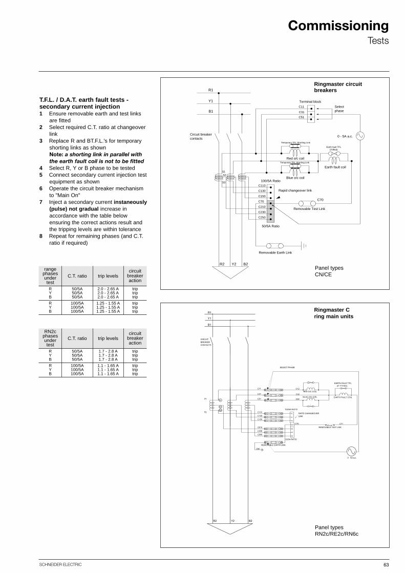
63SCHNEIDER ELECTRIC
CommissioningTests
Removable Earth Link
R1
Y1
B1
Circuit breakercontacts
0 - 5A a.c.
Removable Test Link
50/5A Ratio
C250
C230
C210
C70
C150
C130
C110
100/5A Ratio
Rapid changeover link
Blue o/c coilS3
S2S1
Earth fault coil
Red o/c coil
Temporary TFL Shorting Link
Earth fault TFL(if lifted)
R2 Y2 B2
Selectphase
Terminal block
C11
C31
C51
C70
Temporary TFL Shorting Link
RYB
RYB
50/5A50/5A50/5A
100/5A100/5A100/5A
2.0 - 2.65 A2.0 - 2.65 A2.0 - 2.65 A
1.25 - 1.55 A1.25 - 1.55 A1.25 - 1.55 A
triptriptrip
triptriptrip
rangephasesundertest
C.T. ratio trip levelscircuit
breakeraction
RYB
RYB
50/5A50/5A50/5A
100/5A100/5A100/5A
1.7 - 2.8 A1.7 - 2.8 A1.7 - 2.8 A
1.1 - 1.65 A1.1 - 1.65 A1.1 - 1.65 A
triptriptrip
triptriptrip
RN2cphasesundertest
C.T. ratio trip levelscircuit
breakeraction
T.F.L. / D.A.T. earth fault tests - secondary current injection1 Ensure removable earth and test links
are fitted2 Select required C.T. ratio at changeover
link3 Replace R and BT.F.L.'s for temporary
shorting links as shownNote: a shorting link in parallel withthe earth fault coil is not to be fitted
4 Select R, Y or B phase to be tested5 Connect secondary current injection test
equipment as shown6 Operate the circuit breaker mechanism
to "Main On"7 Inject a secondary current instaneously
(pulse) not gradual increase in accordance with the table below ensuring the correct actions result andthe tripping levels are within tolerance
8 Repeat for remaining phases (and C.T.ratio if required)
Ringmaster circuit breakers
Ringmaster Cring main units
Panel types CN/CE
Panel types RN2c/RE2c/RN6c
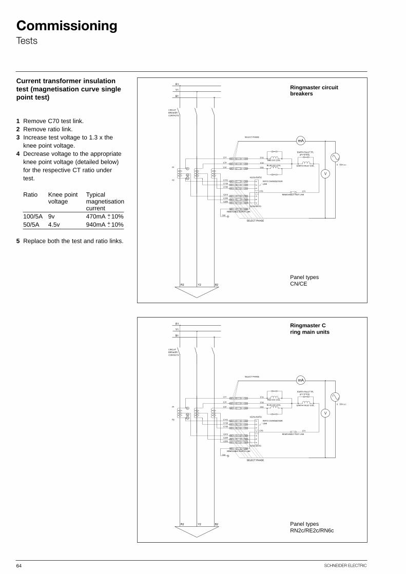
64 SCHNEIDER ELECTRIC
CommissioningTests
Current transformer insulationtest (magnetisation curve singlepoint test)
1 Remove C70 test link.2 Remove ratio link.3 Increase test voltage to 1.3 x the
knee point voltage.4 Decrease voltage to the appropriate
knee point voltage (detailed below) for the respective CT ratio under test.
Ratio Knee point Typicalvoltage magnetisation
current100/5A 9v 470mA 10%50/5A 4.5v 940mA 10%
5 Replace both the test and ratio links.
Ringmaster circuit breakers
Ringmaster Cring main units
Panel types CN/CE
Panel types RN2c/RE2c/RN6c
+-+-

65SCHNEIDER ELECTRIC
CommissioningCommissioning Ringmaster with VIP 300
Since the system is fully tested it is only necessary to prove the relay on site at the servicesettings, therefore reducing commissioning time to a minimum.Once the switchgear has been installed and cabled up, it is impractical or sometimes impossible to carry out injection tests. It is suggested that for commissioning and maintenance purposes either of the following two methods can be used.1. Simple trip test using the VAP6 test unit (described previously).2. Secondary injection using standard equipment with an output filter.
Factory tests:
Testing using secondary injection is used to test the following parts of the protection system:■ The electronic circuit.
■ The integrity of the power supply of the VIP 300.■ The link to the mitop trip coil and also the circuit breaker mechanical tripping
mechanism.■ The integrity of the switches on the front panel to ensure they give the correct tripping times for the curves selected.
■ The “MITOP” trip coil must be used only in conjunction with the VIP relay.■ Voltage withstand testing of the aux i l ia ry and control circuits at 2000V AC for 1 minute
should never be carried out without disconnecting the MITOP trip coil or VIP relay.■ Secondary injection facilities are provided on the terminal rail in the pilot cable box.■ No external connections should be made to the VIP 300 or theMITOP trip coil.
All Ringmaster panel types are fully tested before leaving the factory. These tests include thewhole protection system including current transformers, wiring harness, relay, trip coil and thecircuit breaker itself using primary injection to energise the system. Tripping tests are carriedout using different settings for each of the IDMT and DT curves available on the relay. Thetripping times are measured with a chronometer and its accuracy is verified against the theoretical times calculated.
Note: When using a secondary injectionset with VIP 300 a filter (e.g. FosterSF30) should be used to improve thewave form. If a filter is not used theoperating time of the relay may not follow the theoretical operating times.
VIP 300 IDMT RELAY
P1
P2
S1
S2
C11
MITOP - ITC
S2
CT1
52
P1
P2
S1
S2
P1
P2
S1
S2
C114
5
6
7
8
9
10
C31 C31
C51 C51
C10 C70
C30
C50 C70
C90
8
7
6
5
4
3
2
1
x4 range
minimumoperatingcurrent
950/51
50N/51N10
11
12
13
14
1516
0v
YR B
K8 (-VE)
K7 (+VE)
C7
1
Injection test setwith filter
CB auxiliary contact(for timing purposes)
connect to terminal blocks above for secondary injection
N.B. - Always check against the relevantCB schematic diagram before carryingout tests
MITOP - CB trip coil
40A,80A or 160A
x2 range
minimumoperatingcurrent
20A,40A or 80A
CAUTION
Reduced commissioning
Secondary injection
Test set connections: The injection set is connected to the VIP 300 relay without disconnecting the CT’s. This isdone via the sockets on the terminal rail located in the pilot cable box, just above the relayitself.
Phase overcurrent connections: To test the overcurrent protection the connection should be made across two CT’s (terminalrails no’s 4 to 5, 5 to 6 or 6 to 4).
Earth fault connections: To test the earth fault protection, the connection should be made across one CT(terminal rail no’s 4 to 7, 5 to 7, or 6 to 7).These terminal numbers should be cross checked with the relevant circuit breaker schematicdiagram. Terminals 15 and 16 (not shown above - see Ringmaster selection guide) giveaccess to a normally open contact, which is normally open when the CB is in the open position. This can be used to connect a timing device to measure the opening time of therelay and circuit breaker.The type of test plug used to connect to the DIN rail connectors is a standard 2mm 19A testplug.

66 SCHNEIDER ELECTRIC
CommissioningCommissioning Ringmaster with VIP 300
1. Pick-up check- Increase the current slowly until the appropriate LED indicator starts to blink.
2. Setting check:- Set the current to be injected (a true RMS ammeter should be used to measure the current).- The CB should then be closed and the counter/timer reset. The current should then be applied.- When the CB has operated, the applied current should be turned off if not done automatically.- The time shown on the counter display includes the operating time of the circuit breaker >80ms or <100ms. The actual relay operating time can then be calculated by subtracting this time from the counter reading.
Recommended test procedure for secondary injection:
Note: No connection should be made to the MITOP trip coil from the secondary injection test set.
*Note. These values exceed the rating of the circuit breaker.
RN2c, RE2c, CE2, CN2CT ratio 200/1A
Range x 2 Range x 4Minimum Operating
Current=20ASecondary
injected currentEquivalent
primary current
100mA 20A
120mA 24A
150mA 30A
180mA 36A
210mA 42A
240mA 48A
280mA 56A
320mA 64A
360mA 72A
400mA 80A
450mA 90A
500mA 100A
Minimum OperatingCurrent=40A
Secondary
injected currentEquivalent
primary current
200mA 40A
240mA 48A
300mA 60A
360mA 72A
420mA 84A
480mA 96A
560mA 112A
640mA 128A
720mA 144A
800mA 160A
900mA 180A
1A 200A
RN6cCT ratio 400/1A
Range x 2 Range x 4Minimum Operating
Current=40ASecondary
injected currentEquivalent
primary current
100mA 40A
120mA 48A
150mA 60A
180mA 72A
210mA 84A
240mA 96A
280mA 112A
320mA 128A
360mA 144A
400mA 160A
450mA 180A
500mA 200A
Minimum OperatingCurrent=80A
Secondary
injected currentEquivalent
primary current
200mA 80A
240mA 96A
300mA 120A
360mA 144A
420mA 168A
480mA 192A
560mA 224A
640mA 256A
720mA 288A
800mA 320A
900mA 360A
1A 400A
CE6, RN6cCT ratio 800/1A
Range x 2 Range x 4Minimum Operating
Current=80ASecondary
injected currentEquivalent
primary current
100mA 80A
120mA 96A
150mA 120A
180mA 144A
210mA 168A
240mA 192A
280mA 224A
320mA 256A
360mA 288A
400mA 320A
450mA 360A
500mA 400A
Minimum OperatingCurrent=160A
Secondary
injected currentEquivalent
primary current
200mA 160A
240mA 192A
300mA 240A
360mA 288A
420mA 336A
480mA 384A
560mA 448A
640mA 512A
720mA 576A
800mA 640A *
900mA 720A *
1A 800A *
The test procedure outlined here is only a guide and may need modifying to suitthe different test sets available.
The manufacturers instructions should be read before attempting to secondaryinject the VIP 300 relay.
The VIP 300 relay can be secondary injected like any conventional 1A relay, therefore the output recommended for 1A relays should be used.
Calculate the secondary current to be injected from the equivalent primary current,taking into account the CT’s used and the range selected by connections to theterminals on the back of the relay.
With the VIP 300 connected so as to present the correct burden, the following testscan be carried out:
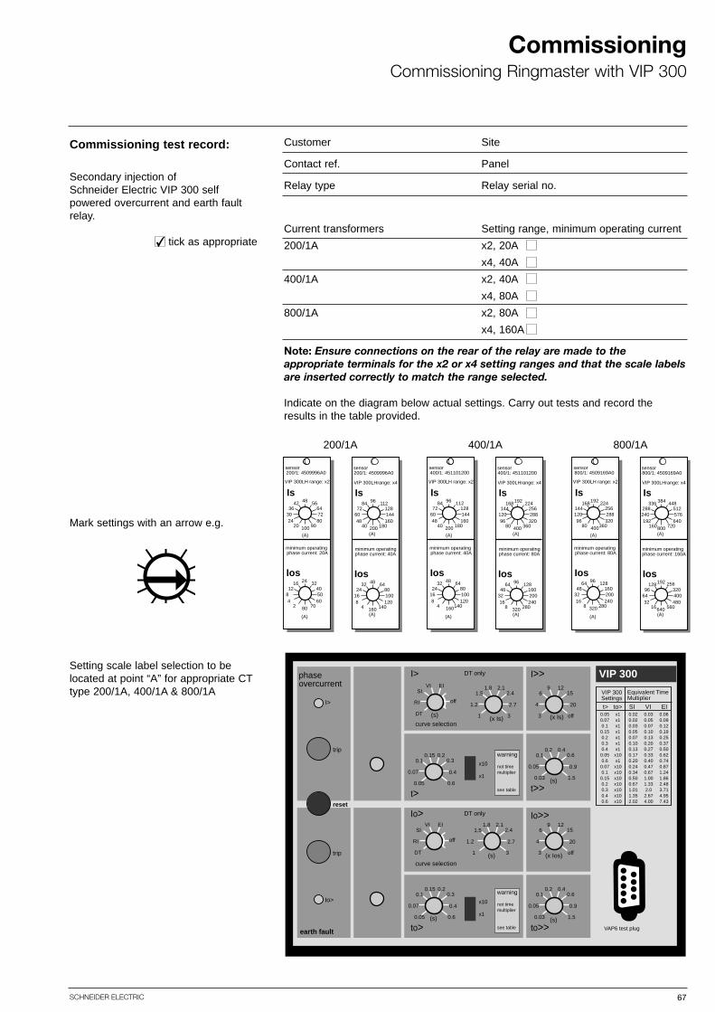
67SCHNEIDER ELECTRIC
CommissioningCommissioning Ringmaster with VIP 300
Customer Site
Contact ref. Panel
Relay type Relay serial no.
Current transformers Setting range, minimum operating current
200/1A x2, 20A
x4, 40A
400/1A x2, 40A
x4, 80A
800/1A x2, 80A
x4, 160A
Note: Ensure connections on the rear of the relay are made to the appropriate terminals for the x2 or x4 setting ranges and that the scale labelsare inserted correctly to match the range selected.
Indicate on the diagram below actual settings. Carry out tests and record theresults in the table provided.
Commissioning test record:
Secondary injection of Schneider Electric VIP 300 self powered overcurrent and earth faultrelay.
✔ tick as appropriate
Mark settings with an arrow e.g.
Setting scale label selection to belocated at point “A” for appropriate CTtype 200/1A, 400/1A & 800/1A
VIP 300LH range: x2
(A)
sensor200/1: 4509996A0
Is4842 56
36 6430 7224 80
20 90100
sensor200/1: 4509996A0
VIP 300LHrange: x4
Is9684 112
72 12860 14448 160
40 180200
minimum operatingphase current: 20A
Ios2416 32
12 408 504 60
2 7080
minimum operatingphase current: 40A
(A)
(A)
Ios4832 64
24 8016 1008 120
4 140160(A)
VIP 300LH range: x2
(A)
sensor400/1: 451101200
Is9684 112
72 12860 14448 160
40 180200
sensor400/1: 451101200
VIP 300LHrange: x4
Is192168 224
144 256120 28896 320
80 360400
minimum operatingphase current: 40A
Ios4832 64
24 8016 1008 120
4 140160
minimum operatingphase current: 80A
(A)
(A)
Ios9664 128
48 16032 20016 240
8 280320(A)
VIP 300LH range: x2
(A)
sensor800/1: 4509169A0
Is192168 224
144 256120 28896 320
80 360400
sensor800/1: 4509169A0
VIP 300LHrange: x4
Is384336 448
288 512240 576192 640
160 720800
minimum operatingphase current: 80A
Ios9664 128
48 16032 20016 240
8 280320
minimum operatingphase current: 160A
Ios192128 256
96 32064 40032 480
16 560640
(A)
(A)
(A)
200/1A 400/1A 800/1A
VIP 300
0.40.20.60.1
0.90.05
1.50.03
to>>(s)
129156
204
off3 (x Is)
0.20.150.30.1
0.40.07
0.60.05
0.40.20.60.1
0.90.05
1.50.03
t>>(s)
129156
204
off3 (x Ios)
2.11.82.41.5
2.71.2
31 (s)
0.20.150.30.1
0.40.07
0.60.05
to>(s)
curve selection
DT onlyIo> Io>>
I>>I>
I>
trip
reset
trip
Io>
earth fault
x10
phaseovercurrent
x1
EIVISI
offRI
DT (s)
2.11.82.41.5
2.71.2
31 (x Is)
x10
x1
VAP6 test plug
EIVISI
offRI
DT
DT only
curve selection
t>
0.050.070.1
0.150.20.30.4
0.050.6
0.070.1
0.150.20.30.40.6
x1x1x1x1x1x1x1x10x1x10x10x10x10x10x10x10
0.020.020.030.050.070.100.130.170.200.240.340.500.671.011.352.02
0.030.050.070.100.130.200.270.330.400.470.671.001.332.0
2.674.00
0.060.090.120.190.250.370.500.620.740.871.241.862.483.714.957.43
t> to> SI VI EI
VIP 300Settings
Equivalent Time Multiplier
warning
not timemultiplier
see table
warning
not timemultiplier
see table
68

68 SCHNEIDER ELECTRIC
CommissioningCommissioning Ringmaster with VIP 300
Commissioning test record
1. Pick up check.Inject the test current into the relay for each phase in turn and note the current required to flash the LED.
2. Operating time and curve check at final settings.Inject the test current into the relay for each phase in turn and note the operating times.
3. Instantaneous trip checkInject the appropriate test current into the relay and ensure the correct instantaneous response.
Curve............... T.............. Curve........... T..............
Phase A-B Phase B-C Phase C-A EF
1. Pick-up current at setting
2. Operating time and curve at finalselected setting
3. Current level to trip high set
Commissioning test record4. Check test facility using
VAP6
Commissioning engineer Date
Customer witness Date
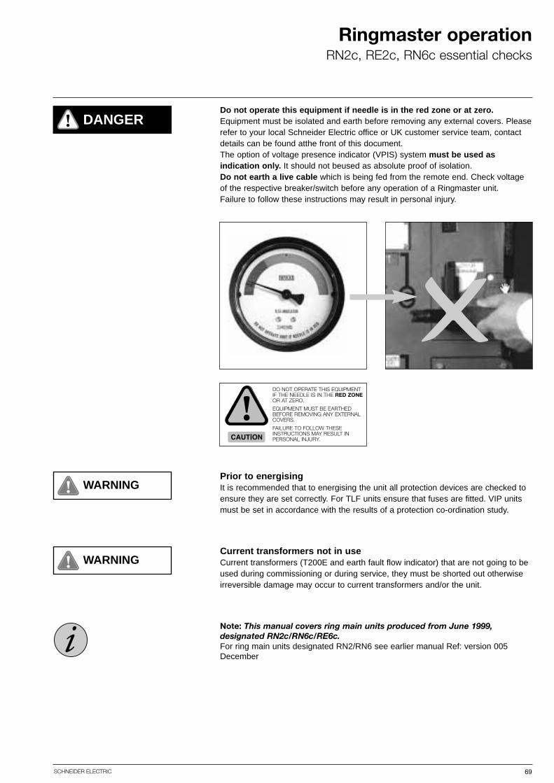
69SCHNEIDER ELECTRIC
Ringmaster operationRN2c, RE2c, RN6c essential checks
WARNING
Do not operate this equipment if needle is in the red zone or at zero.Equipment must be isolated and earth before removing any external covers. Pleaserefer to your local Schneider Electric office or UK customer service team, contactdetails can be found atthe front of this document.The option of voltage presence indicator (VPIS) system must be used as indication only. It should not beused as absolute proof of isolation.Do not earth a live cable which is being fed from the remote end. Check voltageof the respective breaker/switch before any operation of a Ringmaster unit.Failure to follow these instructions may result in personal injury.
! DANGER
Prior to energisingIt is recommended that to energising the unit all protection devices are checked toensure they are set correctly. For TLF units ensure that fuses are fitted. VIP unitsmust be set in accordance with the results of a protection co-ordination study.
✕
WARNINGCurrent transformers not in useCurrent transformers (T200E and earth fault flow indicator) that are not going to beused during commissioning or during service, they must be shorted out otherwiseirreversible damage may occur to current transformers and/or the unit.
Note: This manual covers ring main units produced from June 1999, designated RN2c/RN6c/RE6c.For ring main units designated RN2/RN6 see earlier manual Ref: version 005December
!DO NOT OPERATE THIS EQUIPMENTIF THE NEEDLE IS IN THE RED ZONEOR AT ZERO.
EQUIPMENT MUST BE EARTHEDBEFORE REMOVING ANY EXTERNALCOVERS.
FAILURE TO FOLLOW THESEINSTRUCTIONS MAY RESULT IN PERSONAL INJURY.
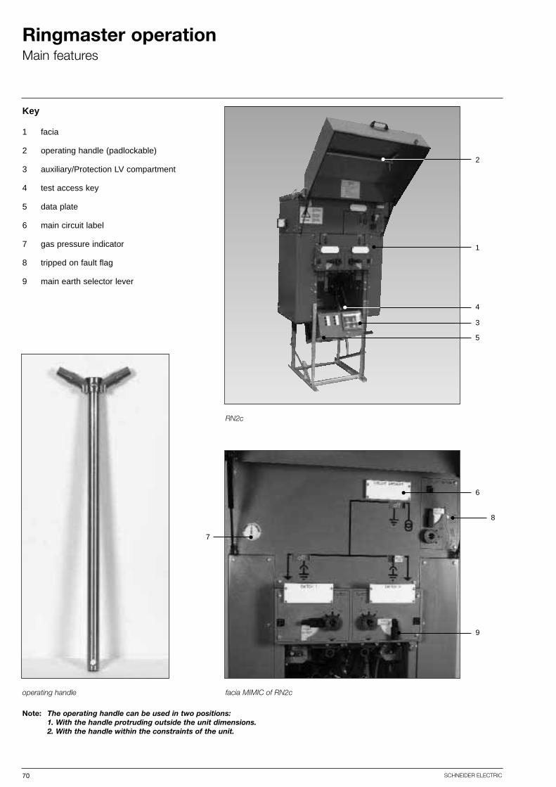
70 SCHNEIDER ELECTRIC
Ringmaster operationMain features
RN2c
facia MIMIC of RN2coperating handle
Key
1 facia
2 operating handle (padlockable)
3 auxiliary/Protection LV compartment
4 test access key
5 data plate
6 main circuit label
7 gas pressure indicator
8 tripped on fault flag
9 main earth selector lever
Note: The operating handle can be used in two positions:1. With the handle protruding outside the unit dimensions.2. With the handle within the constraints of the unit.
7
6
8
9
2
4
3
5
1

71SCHNEIDER ELECTRIC
Ringmaster operationSwitch and circuit breaker
Manual operation of main switch/circuit breaker RN2c, RE2c, RN6c
Lift up hinged door. Check that thegas indicator is in the green, "healthy condition". Check the facia diagramfor the service condition. Remove padlocks if fitted.
Move selector to "Main Switch/Circuitbreaker" position. To operate selectorslide padlock sleeve towards selectorpivot point and rotate selector torequired position.
Insert handle as shown, aligning handle profile and direction of operation (arrow) to unit operationalsocket, for direction of operation.Firmly operate, in a rotational movement, the operating handle untilthe circuit breaker/switch closes.
Padlock fitted to circuit breaker/mainswitch in the “close in service position”.To open, remove “closed in serviceposition” padlock, if fitted, rotate handlethrough 180° and reverse procedure.
The selector lever will be locked in the“main switch/circuit breaker” positionwhen in the “closed in service” position.
Padlock fitted to circuit breaker/mainswitch selector.
Note: To operate to the “main on’ position the operating handle must be rotated in a clockwise direction for the circuit breaker/righthand ring switch and in an anti-clock wise direction for the left hand ring switch (as marked on the unit facia).
Note: The fitting of padlocks does not affect the electrical tripping of the unit.

72 SCHNEIDER ELECTRIC
Ringmaster operationEarth switch
Manual operation of earth switch RN2c, RE2c, RN6c
Lift up hinged door. Check that thegas indicator is in the green, "healthy condition". Check the facia diagramfor the “off” service condition. Remove padlocks if fitted. Move selector to“Earth Switch” position. To operateselector slide padlock sleeve towardsselector pivot point and rotate selectorto required position.
Insert handle as shown, aligning handle profile and direction of operation (arrow), to unit operationalsocket for direction of operation. Firmlyoperate, in a rotational movement, theoperating handle until the earth switchcloses.
The selector lever will be locked in the“earth switch” position when in the“closed in earth” position.
Padlock fitted to earth switch selector. Padlock fitted to earth switch in the“closed in earth position”. To open,remove “closed in earth position” padlock, if fitted, rotate handle through180° and reverse procedure.
Note: To operate to the “earth on’ position the operating handle must be rotated in an anti-clockwise direction for the circuit breaker/right hand ring switch and clockwise direction for the left hand ring switch (as marked on the unit facia).
Note: The unit will not electrically trip if an earth is applied onto a fault.

73SCHNEIDER ELECTRIC
Ringmaster operationCable testing
Cable testing - ring cables RN2c
Open LV compartment by depressinglever on lower edge of LV compartment. Remove padlock if fitted,at this point.
Ensure that the main earth switch is inthe “earth on” position. This will openthe key way.
Key way Insert test key (located inside LV cabinet)into key way.
The test access key will be locked inposition until the cover is firmly closed.Reverse procedure to return to servicecondition. Note: ensure cables are discharged before touching bushingsafter testing.
Turn lever clockwise. Remove testaccess cover padlock if fitted.
Pull test access cover down, utilisingoperating handle, to remove cableearth and provide access to the testingbushings (marked with red, yellow andblue phase dots).

74 SCHNEIDER ELECTRIC
Ringmaster operationCable testing
Cable testing - circuit breaker RN6c
Ensure that the CB earth switch is inthe “earth on” position.This will open the key way for the testkey.
key waytest key
The test key is located on the RN6cfascia as shown above. To remove the key, turn the black lever 90° anti-clockwise.
Insert the test key as shown and turnthe black lever 90° in a clockwise direction to lock in position.
Remove test access padlock (if fitted).Whilst holding black lever of test keydown, raise the CB test access cover.Note that some resistance will beencountered.
Lift CB test access cover clear of testcontacts. Note that the test key is nowlocked in position until the accesscover is firmly closed.Reverse procedure to return CB to service.

75SCHNEIDER ELECTRIC
Ringmaster operationCircuit breaker reset
Circuit breaker reset - electrical trip/tripped on fault RN2c, RE2c, RN6c
Motorpack circuit breaker reset - electrical trip/tripped on fault
Following a circuit breaker electricaltrip/tripped on fault operation the tripping spring has to be reset prior toa close operation. The orange trippedon fault flag (indicated with arrow) willbe displayed following the electricaltrip.
Insert handle as shown, aligning handle profile and direction of operation (arrow) to unit operationalsocket, for direction of operation.Firmly operate, in an anti-clockwiserotational movement, the operatinghandle until the orange tripped on faultflag changes to the white normal service condition, and the handlereaches the end stop.
On the resetting of the flag to whiteallow the operating handle to returnclockwise to the off position.To close the circuit breaker to the service/earth condition, refer to relevant section regarding manualoperation.
When a trip operation has occured, themotor intelligence will automaticallyreset the circuit breaker.
Note: To manually reset circuit breaker remove motorpack and follow above procedure.
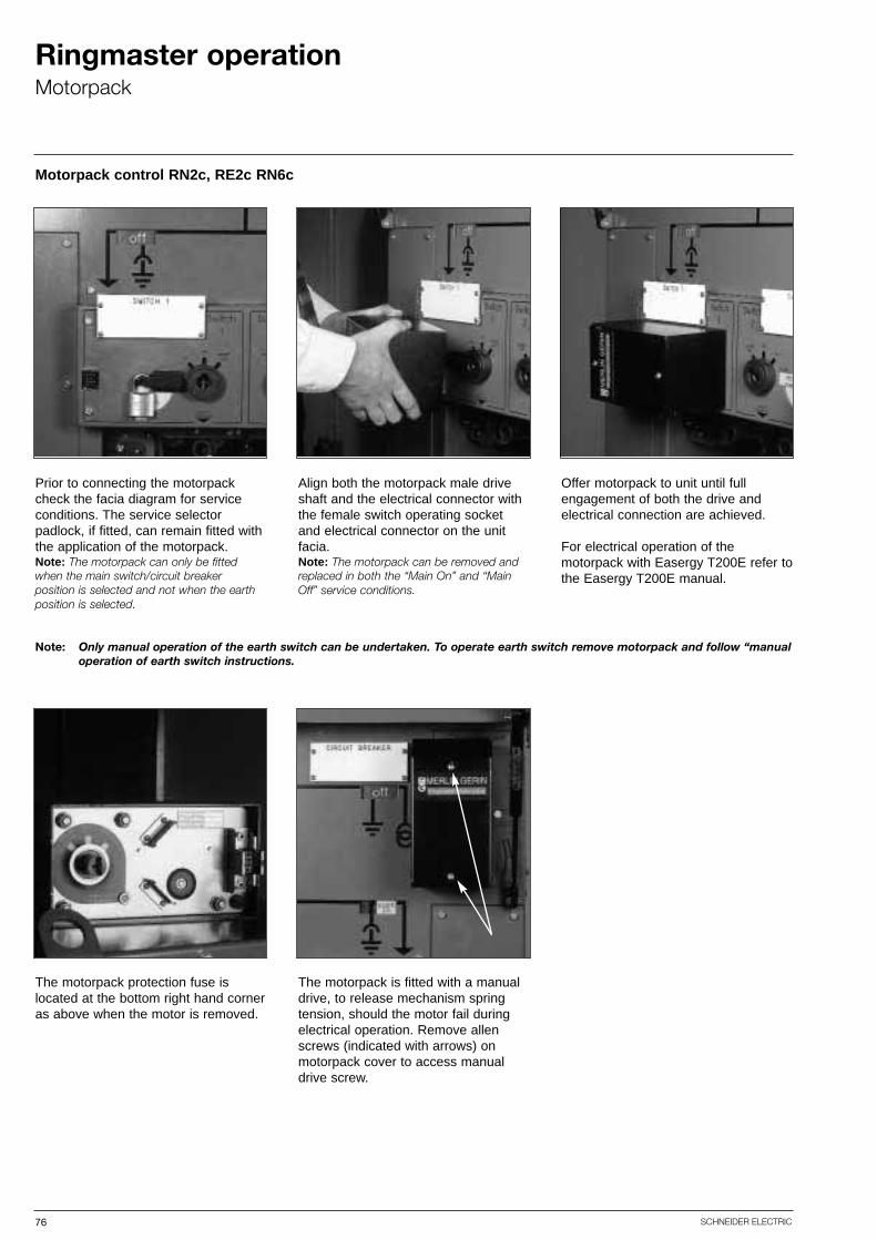
76 SCHNEIDER ELECTRIC
Ringmaster operationMotorpack
Motorpack control RN2c, RE2c RN6c
Prior to connecting the motorpackcheck the facia diagram for serviceconditions. The service selector padlock, if fitted, can remain fitted withthe application of the motorpack.Note: The motorpack can only be fittedwhen the main switch/circuit breaker position is selected and not when the earthposition is selected.
Align both the motorpack male driveshaft and the electrical connector withthe female switch operating socketand electrical connector on the unitfacia.Note: The motorpack can be removed andreplaced in both the “Main On” and “MainOff” service conditions.
Offer motorpack to unit until fullengagement of both the drive and electrical connection are achieved.
For electrical operation of the motorpack with Easergy T200E refer to the Easergy T200E manual.
The motorpack protection fuse is located at the bottom right hand corneras above when the motor is removed.
The motorpack is fitted with a manualdrive, to release mechanism springtension, should the motor fail duringelectrical operation. Remove allenscrews (indicated with arrows) onmotorpack cover to access manualdrive screw.
Note: Only manual operation of the earth switch can be undertaken. To operate earth switch remove motorpack and follow “manualoperation of earth switch instructions.

77SCHNEIDER ELECTRIC
Ringmaster operationMotorpack operation
Motorpack control - RN2c, RN6c and RE2c
Operating voltage, current and time
RN2c/RN6c/RE2c close 24V d.c. 4A 5 sec.
RN2c/RN6c/RE2c open 24V d.c. 4A 5 sec.
RN2c/RN6c/RE2c reset (CB only) 24V d.c. 3.5A 11 sec.
panel type operation voltage current time
Values given are typical and may vary slightly between units.
+ 30%- 10%
+ 30%- 10%
+ 30%- 10%

78 SCHNEIDER ELECTRIC
Ringmaster operationNeon indication
Neon indication
Neon indication can be fitted as an optional item on the ringswitches and circuit breaker on the RN2c. The test socketsare located in the pilot cable box.
A garter spring is fitted to the relevant cable bushing whichforms a capacitive coupling with the HV conductor, derivingthe neon voltage.
Note: Circuit breaker neons cannot be fitted to transformer mounted units.Note: To achieve correct reading when using a phase comparitor please use Pfisterer Electronic Phase Comparator
EPV LRM System No.827 189-007 (available as kit RMR-A25)

79SCHNEIDER ELECTRIC
Ringmaster range operationCN2, SN6, CE2, CE6, SE6, MU2 essential checks
WARNING
Do not operate this equipment if needle is in the red zone or at zero.
Equipment must be isolated and earth before removing any external covers. Pleaserefer to your local Schneider Electric office or UK customer service team, contactdetails can be found atthe front of this document.
The option of voltage presence indicator (VPIS) system must be used as indication only. It should not be used as absolute proof of isolation.
Do not earth a live cable which is being fed from the remote end. Check voltageof the respective breaker/switch before any operation of a Ringmaster unit.
Failure to follow these instructions may result in personal injury.
! DANGER
Prior to energisingIt is recommended that to energising the unit all protection devices are checked toensure they are set correctly. For TLF units ensure that fuses are fitted. VIP unitsmust be set in accordance with the results of a protection co-ordination study.
✕
WARNINGCurrent transformers not in useCurrent transformers (T200E and earth fault flow indicator) are not going to beused during commissioning or during service, they must be shorted out otherwiseirreversible damage may occur to current transformers and/or the unit.
!DO NOT OPERATE THIS EQUIPMENTIF THE NEEDLE IS IN THE RED ZONEOR AT ZERO.
EQUIPMENT MUST BE EARTHEDBEFORE REMOVING ANY EXTERNALCOVERS.
FAILURE TO FOLLOW THESEINSTRUCTIONS MAY RESULT IN PERSONAL INJURY.

80 SCHNEIDER ELECTRIC
Ringmaster range operationMain features
CN2/SN6
CE2/CE6/SE6
8
8
7
10
9
10
1
2
5
1
3
4/6
Key
1 facia
2 operating handle (padlockable)
3 auxiliary/Protection compartment
4 test access key (within LV pilot
box)
5 data plate/pilot box
6 main circuit label on pilot box
7 transformer earth switch
8 gas pressure indicator
9 tripped on fault flag
10 main selector lever

81SCHNEIDER ELECTRIC
Ringmaster range operationSwitch and circuit breaker
Operation of main switch/circuit breaker CE6, CE2, SE6, CN2, SN6
Operation of main earth CE6, CE2, SE6, CN2, SN6
Lift up hinged door. Check that the gasindicator is in the green, "healthy condition". Check the facia diagram forthe service condition. Remove padlocks if fitted.
Move select to "Main Switch" position.Insert handle as shown and pull downfirmly until the circuit breaker/switchcloses. The selector lever will belocked into the "main switch" position.Fit padlock into "CB closed in service"position if required.
Note: That this does not affect electricaltripping of the unit.
To open, rotate the handle through 180° and reverse the procedure.
To open, rotate the handle through180° and reverse the procedure.
Lift up hinged door. Check that the gasindicator is in the green, "healthy condition". Check the facia diagram forthe service condition. Removepadlocks if fitted.
With the switch/circuit breaker in theopen position, move selector lever to"earth switch position". Insert handleas shown and pull down firmly until theswitch closes. The selector will belocked in the "earth switch" position.Fit padlock into "circuit breaker/switchmain cable earthed" if required.
Note: That the unit will not trip on fault.

82 SCHNEIDER ELECTRIC
Ringmaster range operationEarth switch
Transformer earth switch SN6 and CN2 only
Opening earth switch
Open the main switch/circuit breaker.Move the selector lever (see page 81)to earth position. Do not re-close themain earth switch unless incomingcable earth is required. Movetransformer earth selector lever asshown above.
Pull lever forwards as shown to closeearth switch. Push back to rest position. The main selector levershould be locked in the earth position.
The switch can be padlocked "on" asshown above.
The transformer earth can now be padlocked off as shown above. Themain selector lever is now free tomove.
Remove padlock if fitted. Move transformer earth selector lever asshown above.
Turn lever clockwise as shown aboveuntil flag show "off" and mechanism isreset. Turn lever back to the rest position.
Closing earth switch

83SCHNEIDER ELECTRIC
Ringmaster range operationCable testing and actuator control
Cable testing main cable - CE6, CE2, SE6, CN2, SN6 and ring cables
Actuator control
Ensure that the main earth switch is"earth on". This will open the key way.
Insert test key (located in pilot cablebox compartment) into key way andturn lever anti-clockwise. Remove testaccess cover padlock if fitted.
Pull test access cover down to removecable earth and provide access to thetesting bushings, (marked with red, yellow and blue phase spots). The testaccess key will be locked in positionuntil the cover is firmly closed.Reverse procedure to return to servicecondition.Note: Ensure cables are discharged
before touching bushings after testing.
Rotate actuator mechanism anti-clockwise away from the handlesocket. Manual operation can be performed as normal. Reverse theprocedure to fit the actuator.
For electrical operation of the actuatorsee page 84 (if using Easergy T200Erefer to the Easergy manual).To earth the main cable, the actuatormust be removed. With the switch/circuit breaker in the open position, disconnect the actuator supply.
Lift the lever on the connecting bracket.

84 SCHNEIDER ELECTRIC
Actuator control - CE2, CE6, SE6 and SN6
Operating voltage, current and time
CE2/CE6 close 24V d.c. 9A 7 sec.
CE2/CE6 open 24V d.c. 5A 7 sec.
SE6/SN6 close 24V d.c. 5A 7 sec.
panel type operation voltage current time
SE6/SN6 open 24V d.c. 5A 7 sec.
Ringmaster range operationActuator control
+ 30%- 10%
+ 30%- 10%
+ 30%- 10%
+ 30%- 10%
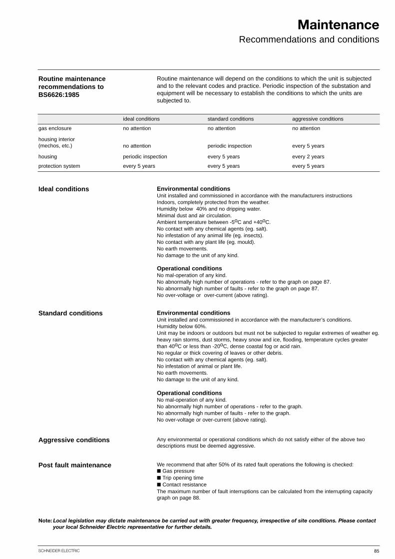
85SCHNEIDER ELECTRIC
MaintenanceRecommendations and conditions
Routine maintenance recommendations toBS6626:1985
Environmental conditionsUnit installed and commissioned in accordance with the manufacturers instructionsIndoors, completely protected from the weather. Humidity below 40% and no dripping water. Minimal dust and air circulation. Ambient temperature between -5oC and +40oC.No contact with any chemical agents (eg. salt). No infestation of any animal life (eg. insects). No contact with any plant life (eg. mould). No earth movements. No damage to the unit of any kind.
Operational conditionsNo mal-operation of any kind. No abnormally high number of operations - refer to the graph on page 87. No abnormally high number of faults - refer to the graph on page 87. No over-voltage or over-current (above rating).
Environmental conditionsUnit installed and commissioned in accordance with the manufacturer’s conditions. Humidity below 60%. Unit may be indoors or outdoors but must not be subjected to regular extremes of weather eg.heavy rain storms, dust storms, heavy snow and ice, flooding, temperature cycles greater than 40oC or less than -20oC, dense coastal fog or acid rain. No regular or thick covering of leaves or other debris. No contact with any chemical agents (eg. salt). No infestation of animal or plant life. No earth movements. No damage to the unit of any kind.
Operational conditionsNo mal-operation of any kind. No abnormally high number of operations - refer to the graph. No abnormally high number of faults - refer to the graph. No over-voltage or over-current (above rating).
Any environmental or operational conditions which do not satisfy either of the above twodescriptions must be deemed aggressive.
Ideal conditions
Standard conditions
Aggressive conditions
Routine maintenance will depend on the conditions to which the unit is subjectedand to the relevant codes and practice. Periodic inspection of the substation andequipment will be necessary to establish the conditions to which the units are subjected to.
ideal conditions
gas enclosure
housing interior(mechos, etc.)
housing
protection system
standard conditions aggressive conditions
no attention no attention no attention
no attention
periodic inspection
periodic inspection
every 5 years
every 5 years
every 2 years
every 5 years every 5 years every 5 years
Note: Local legislation may dictate maintenance be carried out with greater frequency, irrespective of site conditions. Please contactyour local Schneider Electric representative for further details.
We recommend that after 50% of its rated fault operations the following is checked:■ Gas pressure■ Trip opening time■ Contact resistanceThe maximum number of fault interruptions can be calculated from the interrupting capacitygraph on page 88.
Post fault maintenance

86 SCHNEIDER ELECTRIC
MaintenanceHousing
Housing exterior
‘O’ rings must be scrupulously clean and wellgreased with petroleum jelly
RN2c/RN6c/RE2c filler pointModular switch / CB filler point
Check all external fixings, labels and earth connections are present and tight.
Check inside the main door (if fitted) and pilot cable box for heavy deposits of dust,ingress of water or contamination by animal or plant life. Check that the gas indicator is reading in the green zone.
Clean the units thoroughly and touch up paint work as necessary.
Open the main and pilot cable box door. Check that the gas indicator is in thegreen zone and the protector cap is fitted over the gas filler valve.
For circuit breaker panels check the electrical protection system - refer to commissioning instructions.
Check the operation of the unit and all mechanical interlocks.
filler point filler point
Housing interior

87SCHNEIDER ELECTRIC
MaintenanceCircuit breaker
Leakage of SF6 gasIn the extremely unlikely event of a gas leak contact your local Schneider Electric officeor UK customer service team immediately. Contact details can be found in the front ofthis document.
New SF6 gas is nontoxic and non combustible. However when exposed to an electricarc SF6 breaks down and becomes toxic.
Service lifeIf correctly installed and maintained the Ringmaster range of switchgear has a servicelife expectancy of 25 years.
10000
1000
100
10
1
1 10 100 1000 10000 100000
current interrupted (amperes)
num
ber
of
op
erat
ions
Prospective interrupting capacity
16kA version21kA version
The above applies to: RE2c, RE6c, CE2, CE6 and CN2 circuit breakers. It is not applicable to the ring switches of the ring main units or the SE6.

88 SCHNEIDER ELECTRIC
Notes


Merlin Gerin is a world leader in the manufacture and supply of high, medium and low voltage products for the distribution, protection, control and management of electrical systems and is focused on the needs of both thecommercial and industrial sectors. The newly launched VDINetwork Solutions offer provides flexible, configurable ethernet systems for all communication needs.
Square D is a total quality organisation and its business is to put electricity to work productively and effectively, protecting people, buildings and equipment. Its low voltageelectrical distribution equipment, systems and services areused extensively in residential and commercial applications.
Telemecanique is a UK market leader and world expert inautomation and control. It provides complete solutions, withits range of components, Modicon range of high technologyprogrammable controllers (PLCs), multiple fieldbus and ethernet communication networks, HMI, motion control systems, variable speed drives and communications software. In addition, it offers power distribution through prefabricated busbar trunking.
Schneider Electric’s local supportSchneider Electric is committed to supporting its customers at every stage of a project. Our 180 sales engineers, the largestdedicated sales force in the UK electrical industry, operate from 4 customer support centres.
Our sales engineers are skilled at assessing individual requirements and combined with the expert support of our product specialists, will develop the most effective and economical answer taking relevant regulations and standards fully into account.
To access the expertise of the Schneider Electric group, please call 0870 608 8 608. Each customer support centre includesfacilities for demonstrations and training, and presentation rooms fully equipped with audio visual and video, providing excellent meeting facilities.
www.schneider-electric.co.uk
ScotlandSchneider Electric LtdUnit 18 Claremont Centre112a Cornwall Street SouthKinning ParkGlasgow G41 1AA
South WestSchneider Electric LtdPO Box 41Langley RoadChippenhamWiltshire SN15 1JJ
North WestSchneider Electric LtdFirst Floor Market HouseChurch StreetWilmslowCheshire SK9 1AY
Industrial systems and solutions showroomSchneider Electric Ltd, University of Warwick Science Park, Sir William Lyons Road, Coventry CV4 7EZ
Building systems and solutions showroomSchneider Electric Ltd, Stafford Park 5, Telford, Shropshire TF3 3BL
Energy and Infrastructure systems and solutions showroomSchneider Electric Ltd, 123 Jack Lane, Hunslet, Leeds LS10 1BS
Product showrooms
Local customer support centres
Fax 0870 608 8 6060870 608 8 608Nationwide support on one number - call the Customer Information Centre on
member of
.co.uk
SE6251 NOV 2007