resources/resource_documents... · site requirements ... spo 2 related messages.....67 . cas 750...
TRANSCRIPT

www.implox.com

CAS 750 Monitor
Page 2 21-02-0289 REV. 00 09/06
Trademarks
Trademarked names appear throughout this document. Instead of inserting a trademark symbol with each mention of the trade-marked name, the publisher states that it is using the names only for editorial purposes and to the benefit of the trademark owner with no intention of improperly using that trademark.
Masimo SET® is a registered trademark of Masimo, Inc. Possession or purchase of this device does not convey any ex-press or implied license to use the device with replacement parts which would, alone, or in combination with this device, fall within the scope of one or more of the patents relating to this device.
Nellcor® and OxiMax® are registered trademarks and SatSec-onds™ is a trademark of Mallinckrodt, Inc.
Microstream® and FilterLine® are registered trademarks of Oridion Medical 1987 LTD.
YSI® is a registered trademark of Yellow Springs Instrument Com-pany.
MAXNIBP®, Tuff-Cuff®, SoftCheck®, UltraCheck® are registered
trademarks and Safe-Cuff™, CASMED™, and For Every Life and Breath Situation™ are trademarks of CAS Medical Systems, Inc.
Contact Addresses Corporate Office: Authorized Representative in Europe:
CAS Medical Systems, Inc. mossaConsulting GmbH 44 East Industrial Road Bollbrügg 22 Branford, CT 06405 23570 Lübeck U.S.A. Germany Phone: +1 (203) 488-6056 Phone: +49-4502-880-557 in the US: (800) 227-4414
Fax: +1 (203) 488-9438 Fax: +49-4502-880-559
[email protected] [email protected] [email protected] [email protected] www.casmed.com
Please contact the distributor in the country of purchase if product information or service should be required.

CAS 750 Monitor
21-02-0289 REV. 00 09/06 Page 3
General Information
This manual is an integral part of the product and describes its in-tended use. Observance of the manual is a prerequisite for proper product performance and correct operation and ensures patient and operator safety.
The symbol means ATTENTION: Consult accompanying docu-ments.
The warranty does not cover damages resulting from the use of accessories and consumables from other manufacturers.
CAS Medical Systems, Inc. is responsible for the effects on safety, reliability, and performance of the product, only if:
• Assembly, operations, extensions, readjustments, modifica-tions, or repairs are carried out by persons authorized by CAS Medical Systems, Inc.
• The electrical installation of the relevant room complies with the requirements of the appropriate regulations.
• The device is used in accordance with the instructions for use.
• All publications conform to the product specifications and ap-plicable IEC publications on safety and essential performance of electro medical equipment as well as with applicable UL re-quirements and AHA recommendations valid at the time of printing.
For complete Warranty information, refer to the Warranty Policy located on page 129.
The CAS Medical System, Inc. quality management system com-plies with the international standards ISO 13485 and the Council Directive on Medical Devices 93/42/EEC.
Note: The information in this manual applies only to the CAS 750C and 750E software version 3.0 and the CAS 750S software version 1.0. It does not apply to earlier software versions.
Note: Due to continuing product innovation, specifications in this manual are subject to change without notice.
In the U.S. the following caution applies:
Caution: Federal law restricts this device to sale by or on the or-der of a physician or properly licensed practitioner.
Warning: Before using the monitor for the first time, please read the information given in section “Safety” starting on page 14.

CAS 750 Monitor
Page 4 21-02-0289 REV. 00 09/06
About this Manual
Note: This manual addresses all parameters a CAS 750 Monitor can have installed. It remains suitable for use if the monitor, that was purchased, has a sub-set of parameters only. Please refer to those sections that are applicable for the model in use.
Manual Purpose
This manual contains the instructions necessary to operate the CAS 750 monitor safely and in accordance with its functions and intended use.
Intended Audience
This manual is written for clinical professionals. Clinical profes-sionals are expected to have working knowledge of medical pro-cedures, practices, and terminology as required for monitoring of critically ill patients.
Caution: For continued safe use of this equipment, it is necessary that the listed instructions be followed. However, instructions listed in this manual in no way supersede established medical practices concerning patient care.
Conventions
Warning: Directions that warn of conditions that put the patient or the caregiver at risk.
Caution: Directions that help to avoid damaging the monitor or losing data.
Note: Directions that make it easier to use the monitor, something not readily apparent.
Figures: All illustrations in this manual are provided as examples only. They may not necessarily reflect your monitoring setup or data displayed on your monitor.
Revision History
This manual has a revision number located at the bottom of each page. It changes whenever the manual is updated. First Printing: 09/2006.
Read this manual carefully before patient use of the monitor.
CAS Medical Systems, Inc. reserves the right to make changes to this manual and improvements to the product it describes at any time without notice or obligation.
Copyright 2005 CAS Medical Systems, Inc. All rights reserved. No part of this manual may be reproduced without the written per-mission of CAS Medical Systems, Inc.

CAS 750 Monitor
21-02-0289 REV. 00 09/06 Page 5
Contents
Trademarks ...................................................................................2
Contact Addresses ........................................................................2
General Information.......................................................................3
About this Manual..........................................................................4 Manual Purpose........................................................................4 Intended Audience ....................................................................4 Conventions..............................................................................4 Revision History ........................................................................4
1 Safety 15
Indications for Use.......................................................................15
Contraindications.........................................................................15
Installation and Setup ..................................................................16
Device Handling ..........................................................................18
Safety Checks .............................................................................19
Monitoring....................................................................................19
Initial Inspection...........................................................................20
Monitor Checklist .........................................................................21
Patient Environment ....................................................................22
Monitor Classifications of Electrical Insulation .............................22
2 Basic Operations 23
Introduction..................................................................................23 Front View...............................................................................24 Rear View ...............................................................................25 Bottom View............................................................................25
Infrared Communication Port..............................................25 Serial Number Label...........................................................25
Getting Started ............................................................................27 Site Requirements ..................................................................27 Power Requirements...............................................................27 Turning the Monitor On ...........................................................28 Turning the Monitor Off ...........................................................29
Power Fail Message...........................................................29 Battery Operation....................................................................29
Battery Status.....................................................................30 Battery Conditions ..............................................................30

CAS 750 Monitor
Page 6 21-02-0289 REV. 00 09/06
Connecting the Accessories ........................................................31
Front Panel Controls....................................................................32
Main Screen ................................................................................34 Freeze Traces.........................................................................36 Pacemaker Indicator ...............................................................36
History Screens ...........................................................................36 Trend History ..........................................................................37 Alarm History ..........................................................................38 Printing Trend or Alarm History ...............................................38 Erase Trend History Data........................................................39 Erase Alarm History Data........................................................39
Parameters Menu ........................................................................40 CO2 Library .............................................................................41
Audio/Visual Menu.......................................................................41 Auto Dim.................................................................................42
3 Alarms 43
Patient Alarms .............................................................................43 Manifestation of Patient Alarms...............................................43
Equipment Alarms .......................................................................43 Manifestation of Equipment Alarms.........................................43
Silencing Alarms..........................................................................44 No alarm active .......................................................................44 Alarm is active.........................................................................44 Silence Indication....................................................................44
Silence Period is set to “2-Minute” ......................................44 Silence Period is set to “Permanent” ..................................44
Alarm Limits.................................................................................45 Alarm Limits Menu ..................................................................45 Changing Alarm Limits ............................................................46 Saving Alarm Limits ................................................................46 Restore Alarm Limits...............................................................47 Factory Default Alarm Limits ...................................................47
Alarm Volume..............................................................................48
Alarm Delays ...............................................................................48 Stand By mode (750S)............................................................49

CAS 750 Monitor
21-02-0289 REV. 00 09/06 Page 7
4 ECG/Resp 51
Introduction..................................................................................51
Safety ..........................................................................................51
Preparations ................................................................................52 Skin Preparation .....................................................................52 Electrode Placement...............................................................53
3-Leadwire Electrode Placement ........................................53 5-Leadwire Electrode Placement ........................................54
Respiration Monitoring ............................................................55 Electrode Placement for Respiration ..................................55 CVA Filter...........................................................................56 Breath-Weighting................................................................56
ECG/Respiration Monitoring ........................................................57 Monitoring Pacemaker Patients ..............................................57 Disconnection of Lead Wires and Patient Cable......................58
ECG/Respiration Display Window ...............................................59
ECG/Respiration related Settings ................................................59
ECG/Respiration Troubleshooting ...............................................60 ECG/Respiration related Messages ........................................60
5 SpO2 61
Introduction..................................................................................61
Safety ..........................................................................................61
SpO2 Sensors..............................................................................62
Preparations ................................................................................63
SpO2 Monitoring ..........................................................................63 SatSeconds™ Alarm Management .........................................64 Disconnecting SpO2 Accessories ............................................65
SpO2 Display Window..................................................................65
SpO2 related Settings...................................................................65
SpO2Troubleshooting ..................................................................66 SpO2 related Messages...........................................................67

CAS 750 Monitor
Page 8 21-02-0289 REV. 00 09/06
6 NIBP 71
Introduction..................................................................................71
Safety ..........................................................................................71
Preparations ................................................................................73 Patient Mode Selection ...........................................................73 NIBP Hose Selection...............................................................73 Cuff Selection .........................................................................73 Cuff Application.......................................................................74
NIBP Measurements ...................................................................75 Starting a Blood Pressure Reading .........................................76 Stopping a Blood Pressure Reading .......................................76 Entering the Cycle Mode.........................................................77 Terminating the Cycle Mode ...................................................77 STAT Mode.............................................................................77
Entering STAT Mode ..........................................................78 Exiting STAT Mode.............................................................78
NIBP Display Window..................................................................79
NIBP Menu ..................................................................................79 To enter the NIBP Menu .........................................................79 Menu Options .........................................................................80 Operating the NIBP Menu .......................................................80
NIBP related Settings ..................................................................80
NIBP Troubleshooting..................................................................81 NIBP related Messages ..........................................................81
7 CO2 83
Introduction..................................................................................83
Safety ..........................................................................................83
Preparations ................................................................................84 Microstream CO2 Consumables ..............................................84 Non-Intubated Application.......................................................84 Intubated Applications.............................................................85
CO2 Monitoring ............................................................................85 Removing the CO2 Consumables............................................86
CO2 Display Window ...................................................................86
CO2 related Settings ....................................................................87
CO2 Troubleshooting ...................................................................87 CO2 related messages ............................................................87
CAS 750 Monitor
21-02-0289 REV. 00 09/06 Page 9
8 TEMP 89
Introduction..................................................................................89
Safety ..........................................................................................89
Preparations ................................................................................89
Temperature Monitoring ..............................................................89
Temperature Display Window......................................................90
Temperature related Settings ......................................................90
Temperature Troubleshooting......................................................90 Temperature related Messages ..............................................90
9 Setup 91
Entering the Setup Menu .............................................................91
Selecting the Language...............................................................92
Selecting Patient Mode................................................................92
Configure Audio Silencing ...........................................................93
Setting the Date...........................................................................93
Setting the Time ..........................................................................94
Daylight Saving Time Option .......................................................94
Pacemaker Detection ..................................................................95
Selecting CVA Filter ....................................................................95
Selecting Alarm Delay .................................................................95
Selecting CO2 Units .....................................................................96
Selecting Temperature Units .......................................................96
Selecting Monitor Set-Up Default.................................................96
Selecting Display Background .....................................................97

CAS 750 Monitor
Page 10 21-02-0289 REV. 00 09/06
10 Cleaning 99
Cleaning the Monitor ...................................................................99
Cleaning Patient Cable and Leadwires ......................................100
Cleaning Cuffs and Pneumatic Hoses .......................................100
Cleaning the SpO2 Interconnect Cable ......................................100
Cleaning SpO2 Sensors.............................................................101
Cleaning Temperature Probes...................................................101
Cleaning CO2 Consumables ......................................................101
Cleaning the Printer...................................................................101
11 Maintenance 103
Maintenance Intervals................................................................103
Maintenance Checks .................................................................104 Entering the Service Menu....................................................104 Exiting the Service Menu ......................................................104 IrDA Test...............................................................................105 CO2 Calibration Check ..........................................................105 CO2 Calibration .....................................................................106 NIBP Checks ........................................................................108
Pneumatic Pressure Check ..............................................108 Calibration Check and Overpressure Test ........................109
PIC Voltage...........................................................................110
Other Checks ............................................................................110 Temperature Calibration Check ............................................110
Battery Replacement .................................................................111 Removing the Battery............................................................111 Inserting the Battery..............................................................112
Fuse Replacement ....................................................................112
Software Versions .....................................................................113
Storage......................................................................................114
12 Printer 115
Printer Controls and Indicators ..................................................116
Printer Operation .......................................................................116 Direct Connection .................................................................116 Infrared Connection ..............................................................117

CAS 750 Monitor
21-02-0289 REV. 00 09/06 Page 11
Charging the Printer Battery ......................................................119
Installing Paper..........................................................................120
Removing the Battery Pack .......................................................121
Installing the new Battery Pack:.................................................122
13 External Device Interfacing 123
Nurse Call and RS232 Interface ................................................123 RS232 Interface ....................................................................123 Nurse Call Interface ..............................................................123
Mounting....................................................................................124
14 Appendix 125
Symbols ....................................................................................125 Front Panel Symbols.............................................................125 Screen Indicators ..................................................................126 Symbols near Accessory Connections ..................................126 Symbols on Monitor or Printer...............................................127 Symbols on Packaging..........................................................128
Warranty Policy .........................................................................129
Monitor Error Messages ............................................................131
Monitor Configurations...............................................................132 CAS 750 Models with AC Power Supply ...............................132 CAS 750 Models with 12 VDC Power Input...........................133
Monitor Configuration Record ....................................................134
Specifications ............................................................................135
Certificates ................................................................................144 Electronic Emissions and Immunity.......................................144 CE Marking Information ........................................................146
Accessories ...............................................................................147 ECG Accessories..................................................................147 Tuff-Cuff Blood Pressure Cuffs .............................................147 Safe-Cuff Blood Pressure Cuffs ............................................147 Inflation Hoses ......................................................................148 Masimo SpO2 Accessories....................................................148 Nellcor SpO2 Accessories .....................................................149 Temperature Accessories .....................................................149 Capnography Accessories ....................................................149 Other Accessories and Options.............................................150

CAS 750 Monitor
Page 12 21-02-0289 REV. 00 09/06
Figures
Figure 1: Patient Environment ..................................................... 22
Figure 2: Front View .................................................................... 24
Figure 3: Rear View of Monitors .................................................. 25
Figure 4: Turning the Monitor On................................................. 28
Figure 5: Left Side View............................................................... 31
Figure 6: Front Panel Controls..................................................... 32
Figure 7: Main Screen ................................................................. 35
Figure 8: Trend History Screen.................................................... 37
Figure 9: Alarm History Screen.................................................... 38
Figure 10: Parameters Menu ....................................................... 40
Figure 11: Audio/Visual Menu...................................................... 41
Figure 12: Alarm Limits Menu ...................................................... 45
Figure 13: Adult and Neonatal Electrode Placement.................... 53
Figure 14: 5-Lead Placement....................................................... 54
Figure 16: Detaching the Lead Wires........................................... 58
Figure 17: Detaching the Patient Cable ....................................... 59
Figure 18: Cuff Application Range Marker ................................... 74
Figure 19: Cuff Application .......................................................... 74
Figure 20: NIBP Menu ................................................................. 79
Figure 21: Setup Menu ................................................................ 91
Figure 22: Service Menu............................................................ 104
Figure 23: Removing the Battery Pack ...................................... 111
Figure 24: Software Versions..................................................... 113
Figure 25: Printer Controls and Indicators.................................. 116
Figure 26: History Sample Printouts .......................................... 118
Figure 27: Waveform Sample Printout ....................................... 119
Figure 28: Paper Installation...................................................... 120
Figure 29: Opening the Battery Door ......................................... 121
Figure 30: Installing the New Battery ......................................... 122
Figure 31: DB9 Connector ......................................................... 123
Figure 32: Mounting Threads..................................................... 124

CAS 750 Monitor
21-02-0289 REV. 00 09/06 Page 13
Tables
Table 1: Factory Default Alarm Limits .......................................... 47
Table 2: 3-Lead Color and Coding............................................... 53
Table 3: 5-Lead Color and Coding............................................... 54
Table 4: CAS 750 Models with AC Power.................................. 132
Table 5: CAS 750 Models with DC Power.................................. 133

CAS 750 Monitor
Page 14 21-02-0289 REV. 00 09/06
This page is intentionally left blank
CAS 750 Monitor Safety
21-02-0289 REV. 00 09/06 Page 15
1 Safety
The following Warnings, Cautions and Notes have to be obeyed to guaranty a safe operation of the monitor. Additional Warnings, Cautions and Notes, which apply to specific parameters, are listed in the related sections for each parameter.
Indications for Use
The 750 Patient Monitor is intended to continuously monitor a pa-tients ECG, heart rate, noninvasive blood pressure (NIBP), func-tional arterial oxygen saturation (SpO2), respiration rate, tempera-ture and end tidal carbon dioxide (CO2). The monitor is designed as a bedside/portable monitor and is intended for use on adult, pediatric and neonatal patients in the care of health care profes-sionals.
Contraindications
• ECG electrodes are contraindicated for use on patients with limited skin access or allergic reaction to electrode adhesive or application gel.
• Reusable ECG electrodes are contraindicated for use for pro-longed periods of use. It is not intended for long term monitor-ing. Electrodes must be removed and repositioned if indicated by skin integrity, and reapplied to a different monitoring site.
• Respiration monitoring is contraindicated for patients who are receiving high frequency ventilation assistance.
• Reusable SpO2 sensors are contraindicated for use for pro-longed periods of use. It is not intended for long term monitor-ing. It must be removed and repositioned every four (4) hours and if indicated by circulatory condition or skin integrity, reap-plied to a different monitoring site.
• Disposable SpO2 sensors are contraindicated for patients that exhibit allergic reactions to adhesive tape. The sensors must be removed and repositioned every eight (8) hours and if indi-cated by circulatory condition or skin integrity, reapplied to a different monitoring site.
• No other contraindications are known at this time.

Safety CAS 750 Monitor
Page 16 21-02-0289 REV. 00 09/06
Installation and Setup
Follow the instructions given in paragraph “Site Requirements” on page 27 and “Power Requirements” on page 27.
Warning: The monitor is not intended for diagnostic use. The health care professional should seek a full capability ECG system for diagnostic purposes.
Warning: Do not come into contact with patients during defibrilla-tion. Otherwise serious injury or death could result.
Warning: The CAS 750 Monitor is intended only as an adjunct in patient assessment. It must be used in conjunction with clinical signs and symptoms.
Warning: Do not rely exclusively on the audible alarm system for patient monitoring. Adjustment of alarm volume to a low level dur-ing patient monitoring may result in a hazard to the patient. Re-member that the most reliable method of patient monitoring com-bines close personal surveillance with correct operation of monitor-ing equipment.
Warning: Do not use the CAS 750 monitor for any purpose other than specified in this manual. Doing so will invalidate the monitor’s warranty.
Warning: Do not connect more than one patient to a monitor. Do not connect more than one monitor to a patient.
Warning: Leakage Current Test - The interconnection of auxiliary equipment, including a patient monitor or other patient connected equipment, with this device may increase the total leakage current. When interfacing with other equipment, qualified biomedical engi-neering personnel must perform a test for leakage current before using it with patients. Serious injury or death could result if the leakage current exceeds applicable standards.
Warning: Do not use the CAS 750 monitor for Open Heart Appli-cations (Intracardiac Application).
Warning: The CAS 750 Monitor is not intended to be used in Oxy-gen Enriched Atmospheres.
Warning: The CAS 750 Monitor is defibrillator proof. It may re-main attached to the patient during defib., but the readings may be inaccurate during use and less than ten (10) seconds thereafter.
Warning: Do not use the monitor in the presence of Magnetic Resonance Imaging (MRI) equipment.
CAS 750 Monitor Safety
21-02-0289 REV. 00 09/06 Page 17
Warning: The CAS 750 Monitor is not “Category AP or APG Equipment”.
Warning: Explosion Hazard - Do not use the monitor in the pres-ence of a flammable Anesthetic Mixture with Air or with Oxygen or Nitrous Oxide.
Warning: Explosion Hazard - Do not use this equipment in the presence of flammable anesthetics, vapors or liquids.
Warning: Electromagnetic Compatibility (EMC) - The equipment needs special precautions if it is placed close to a strong transmit-ter such as X-ray equipment, MRI devices, TV, AM/FM radios, po-lice/ fire stations, a HAM radio operator, an airport, or cellular phone. Their signals could interfere with the monitor, which may result in disruption of performance of this device or prevents the clear reception of signals by the monitor.
Caution: Qualified biomedical engineering personnel only must in-terface monitoring equipment with other types of medical equip-ment. Be certain to consult manufacturers’ specifications to main-tain safe operation.
Caution: Measurements may be affected in the presence of strong electromagnetic sources such as electro surgery equipment.
Note: The CAS 750 Monitor is designed for continuous operation.
Note: The CAS 750 Monitor is suitable for use in the presence of electro surgery.
Note: The CAS 750 Monitor can remain connected to the patient during Cardio Defibrillation. ECG applied parts are “Type CF Defi-brillation Proof”. All other applied parts are “Type BF Defibrillation Proof”.
The monitor has been designed to promote patient safety. All equipment parts are protected against the effects of the discharge of a defibrillator. No separate actions are required when using this equipment with a defibrillator.
Safety CAS 750 Monitor
Page 18 21-02-0289 REV. 00 09/06
Device Handling
Warning: To ensure patient safety, do not place the monitor in any position that might cause it to fall on the patient.
Warning: Do not lift the monitor by any sensor cable or line as they could disconnect from the monitor, causing the monitor to fall on the patient.
Warning: To avoid electric shock or device malfunction, liquids must not be allowed to enter the device. If liquids have entered a device, take it out of service and have it checked by a service tech-nician before it is used again.
Warning: The CAS 750 Monitor provides “DRIP-PROOF” level of protection from ingress to moisture.
Warning: Do not place liquids on top of the monitor. Do not im-merse the monitor or power cord in water or any liquid.
Warning: Do not gas sterilize or autoclave the monitor.
Warning: Do not touch part of non-medical electrical equipment in the patient environment after removal of covers, connectors etc… without the use of a tool which operate at voltages not exceeding 25 VAC or 60 VDC and the patient at the same time.
Warning: Where the integrity of the external protective conductor in the installation or its arrangement is in doubt, EQUIPMENT shall be operated from its INTERNAL ELECTRICAL POWER SOURCE.
Warning: Isolation of product from mains can only be achieved by removal of external power cord.
Warning: Route all cables away from patient’s throat to avoid pos-sible strangulation.
Caution: Pressing the front panel keys with a sharp or pointed in-strument may permanently damage the switch membrane. Press the keys using only your finger.
Caution: If the monitor is accidentally wetted, take it out of opera-tion. It should be thoroughly dried. To verify the absence of water, a qualified service technician can remove the rear cover.
Caution: To avoid the risk of electrical shock, do not remove the back cover. Refer all servicing to qualified personnel.
Note: There are no known risks with common disposal of equip-ment or accessories; however, the disposing of accessories should follow in accordance with local hospital policies. The user should ensure these policies do not conflict with any local, state or federal guidelines.

CAS 750 Monitor Safety
21-02-0289 REV. 00 09/06 Page 19
Safety Checks
Warning: Do not, under any circumstances, perform any testing or maintenance on the monitor or power cord while the unit is being used to monitor a patient. Unplug the power cord before cleaning or servicing the monitor. The operator should not perform any ser-vicing except as specifically stated in this manual.
Warning: The functions of the alarm system for monitoring of the patient must be verified at regular intervals.
Warning: Periodically, and whenever the integrity of the product is in doubt, test all functions.
Warning: Do not use a frayed or damaged power supply cord or any accessory if you notice any sign of damage. Contact CAS Medical Systems for assistance.
Warning: The use of Accessory equipment not complying with the equivalent safety requirements of this equipment may lead to a re-duced level of safety of the resulting system. Consideration relat-ing to the choice shall include:
- Use of the accessory in the Patient Environment.
- Evidence that the safety certification of the Accessory has been performed in accordance to the appropriate IEC 601-1 and/or IEC 601-1-1 harmonized national standard.
Caution: Inspect the monitor, patient cables, sensors and air hose for damage prior to operation. If any damage is noted, the monitor should not be used until it has been serviced. Only personnel au-thorized to do so by CAS Medical Systems, Inc. should repair the monitor.
Caution: If the monitor fails to respond, do not use it until the situation has been corrected by qualified personnel.
Monitoring
Warning: Conductive Connections - Extreme care must be exer-cised when applying medical electrical equipment. Many parts of the human/machine circuit are conductive, such as the patient, connectors, electrodes, and transducers. It is very important that these conductive parts do not come into contact with other grounded, conductive parts when connected to the isolated patient input of the device. Such contact would bridge the patient's isola-tion and cancel the protection provided by the isolated input. In particular, there must be no contact of the neutral electrode and ground.

Safety CAS 750 Monitor
Page 20 21-02-0289 REV. 00 09/06
Warning: If the accuracy of any value displayed on the monitor or printed on a graph strip is questionable, determine the patient's vi-tal signs by alternative means. Verify that all equipment is working correctly.
Warning: Only use protected leadwires and patient cables with this monitor. The use of unprotected leadwires and patient cables creates the potential for making an electrical connection to ground or to a high voltage power source which can cause serious injury or death to the patient.
Caution: Use only CAS approved accessories and sensors to en-sure patient safety and to preserve the integrity, accuracy and the electromagnetic compatibility of the monitor.
Caution: Use only CAS approved ECG cables to ensure proper defibrillation protection.
Caution: Electrocautery - To prevent unwanted skin burns; apply electrocautery electrodes as far as possible from all other elec-trodes, a distance of at least 15 cm (6 in.) is recommended.
Initial Inspection
Before unpacking the monitor, inspect the packaging for damage. If there are any signs of damage to the package, a claim should be filed immediately with the shipping agent. It is the receiver's responsibility to notify the carrier's local office to arrange for the pickup of the damaged items. Save the damaged shipping carton as evidence.
Contact your distributor, CAS sales representative, or call CAS Medical Systems, Inc. to report external damage and to arrange for repair or replacement of damaged equipment.
The shipping carton should contain the items listed below. Un-pack the monitor and account for each item. Inspect each item for signs of external damage, dents, cracks, scratches, etc. If an item is missing or damaged, contact your distributor, CAS sales repre-sentative, or CAS Medical Systems, Inc.
Record the monitor model, serial number and date of purchase at the back of this manual.

CAS 750 Monitor Safety
21-02-0289 REV. 00 09/06 Page 21
Monitor Checklist
• (1) CAS 750C, E or S Monitor Depending on model ordered
• (1) Hospital Grade AC Power Cord or DC Power Cord Depending on model ordered
• (1) 3-Lead ECG/Respiration Patient Cable For models with ECG installed
• (1) Lead Wire Set For models with ECG installed
• (1) Temperature Adapter Cable For models with Temperature installed
• (1) SpO2 Interconnect Cable For models with SpO2 installed
• (1) SpO2 Finger Sensor For models with SpO2 installed
• (2) FilterLine Set, Adult/Pediatric For models with CO2 installed
• (2) Smart CapnoLine, Adult For models with CO2 installed
• (1) Ten (10) Foot Coiled Inflation Hose For models with NIBP installed
• (1) Blood Pressure Cuffs, Adult For models with NIBP installed
• (1) Blood Pressure Cuffs, Child For models with NIBP installed
• (1) P9 Calibration Kit For models with NIBP installed
• (1) CAS 750 Monitor User’s Manual
Caution: Use only the CAS approved power cord that was shipped with the monitor to preserve the electromagnetic compati-bility of the monitor.
Note: The monitor is shipped with the appropriate line cord for the country and/or voltage being used.
Safety CAS 750 Monitor
Page 22 21-02-0289 REV. 00 09/06
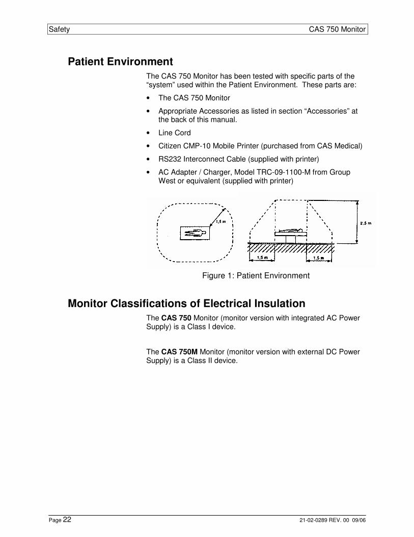
Patient Environment
The CAS 750 Monitor has been tested with specific parts of the “system” used within the Patient Environment. These parts are:
• The CAS 750 Monitor
• Appropriate Accessories as listed in section “Accessories” at the back of this manual.
• Line Cord
• Citizen CMP-10 Mobile Printer (purchased from CAS Medical)
• RS232 Interconnect Cable (supplied with printer)
• AC Adapter / Charger, Model TRC-09-1100-M from Group West or equivalent (supplied with printer)
Figure 1: Patient Environment
Monitor Classifications of Electrical Insulation
The CAS 750 Monitor (monitor version with integrated AC Power Supply) is a Class I device.
The CAS 750M Monitor (monitor version with external DC Power Supply) is a Class II device.

CAS 750 Monitor Basic Operation
21-02-0289 REV. 00 09/06 Page 23
2 Basic Operations
Introduction
The CAS 750 Monitor is a pre-configured monitor that can include the following measurement functions:
• ECG / Respiration / Temperature
• Pulse Oximetry (SpO2)
• Non Invasive Blood Pressure (NIBP)
• Capnography (CO2)
The ECG signal and the thorax impedance are measured through the same set of electrodes. Patients can be monitored with a three-lead or five-lead ECG cable. ECG and respiration signals can be displayed as waveforms. Temperature is obtained using a thermistor applied to the patient’s skin.
The Pulse Oximeter function continuously monitors and displays values for functional arterial hemoglobin saturation (%SpO2) and the pulse rate (PR). The dynamic pulse signal can be displayed as a waveform (Plethysmogram) or as a bar graph indicator.
The non-invasive blood pressure measurement uses the oscil-lometric method and applies for neonatal, pediatric and adult pa-tients. The user can select between manual, cycle or continuous (STAT) mode.
The MicroStream Capnography provides continuous monitoring of the EtCO2 value and the Respiration Rate (RR) of intubated and non-intubated patients. The CO2 signal can be displayed as a waveform.
The monitor is equipped with a rechargeable battery pack and can be used independently from an external power source.

Basic Operation CAS 750 Monitor
Page 24 21-02-0289 REV. 00 09/06
Front View
Figure 2: Front View

CAS 750 Monitor Basic Operation
21-02-0289 REV. 00 09/06 Page 25
Rear View
Figure 3: Rear View of Monitors
(M-Version shown below)
1. Battery Compartment
2. External Device Interface (RS232)
3. Receptacle for the AC power cord
4. Fuse Compartment
5. Receptacle for the 12 VDC cable
Bottom View
Infrared Communication Port
An Infrared (Ir) output port, located on the bottom panel of the monitor’s front cover, is available to print Waveforms, History and Alarm data to the optional external printer or other data collection device(s). Maximum distance is approximately 3 feet, direct line of sight operation.
Serial Number Label
The serial number label is located on the bottom of the monitor.

Basic Operation CAS 750 Monitor
Page 26 21-02-0289 REV. 00 09/06
This page is intentionally left blank

CAS 750 Monitor Basic Operation
21-02-0289 REV. 00 09/06 Page 27
Getting Started
Site Requirements
Note: Put the monitor in a location where you can easily see the screen and access the operating controls.
Caution: Stacking - Where monitor is used adjacent to or stacked with other equipment, the monitor should be observed to verify normal operation in the configuration in which it will be used.
Caution: Negligence - CAS Medical Systems Inc. does not as-sume responsibility for damage to the equipment caused by im-properly vented cabinets, improper or faulty power, or insufficient wall strength to support equipment mounted on such walls.
Power Requirements
The external power for the CAS 750 Monitor can be either AC mains power or DC power. The two different models are:
• Model CAS 750M for +12V VDC
• Model CAS 750 for 110 to 240 VAC
The following applies for the CAS 750 model with AC power sup-ply:
Warning: Do not plug the monitor into an outlet controlled by a wall switch or dimmer.
Warning: Where the integrity of the external protective conductor in the installation or its arrangement is in doubt, EQUIPMENT shall be operated from its INTERNAL ELECTRICAL POWER SOURCE.
Warning: Isolation of product from mains can only be achieved by removal of external power cord.
Caution: Do not defeat the three-wire grounding feature of the power cord by means of adaptors, plug modifications, or other methods. Do not use extension cords of any type.
Note: The monitor is suitable to be connected to public AC mains power.

Basic Operation CAS 750 Monitor
Page 28 21-02-0289 REV. 00 09/06
Turning the Monitor On
Press the POWER key on the front panel to turn the monitor on.
Figure 4: Turning the Monitor On Each time the monitor is turned on an internal self-test is con-ducted to ensure that all circuits are functioning properly. Verify the following:
• The monitor produces 3 one-second audio beeps.
• Both, the Equipment and the Alarm Indicators are lit for one-half second and cycled one after the other.
• The monitor displays temporarily its current configuration data:
• Model number (750C, E or S)
• Power source (E=External AC, EM=External DC)
• Number of installed parameters
• Brand of installed parameters (MS = Masimo, NL = Nellcor, C = Oridion)
Note: If after the Power-On-Self-Test is completed the monitor displays “NIBP Cal” in the Equipment Message area, the monitor should be returned to CAS Medical Systems for service.
Once the Power-On-Self-Test is completed, the monitor’s Main screen is activated and the monitor is ready for use.

CAS 750 Monitor Basic Operation
21-02-0289 REV. 00 09/06 Page 29
Turning the Monitor Off
When the monitor is not being used, it may be turned off by press-ing the POWER key for 2 seconds. The display will turn blank and the unit is no longer monitoring the patient.
Note: The internal power supply is not switched off! It remains connected to the external power source (AC or DC) to enable bat-tery charging.
Power Fail Message
During the internal self-test the monitor checks whether it was pre-viously turned off correctly or if it was disconnected from power in any other way. The user will be alerted about such a power loss after the monitor is turned on again.
The message “Power Failure” is displayed in the Equipment Mes-sage Window, the Equipment Alarm LEDs are activated and 3 beeps followed by 2 beeps are heard every 10 seconds.
• Press the SILENCE/RESET key to clear the Power Fail condi-tion.
Note: Only the SILENCE/RESET and the ON/STANDBY keys are operable, all other keys are disabled while the message is dis-played.
Battery Operation
The monitor is equipped with a rechargeable battery. The battery is charging whenever the monitor is connected to an external power source (AC Line Power or +12 VDC).
Batteries will self-discharge when they are not used. It is recom-mended leaving the monitor connected to an external power source whenever possible.
The monitor will operate on a completely charged battery for 3 to 5 hours depending on its configuration and the use of the NIBP function.
Basic Operation CAS 750 Monitor
Page 30 21-02-0289 REV. 00 09/06
Battery Status
There are several means to get an indication about the battery charge status:
• When the monitor is connected to external power and turned off, the Main screen displays the Battery Indicator icon with a moving bar from left to right within the indicator signifying the battery is being charged. Once charged, the moving bar will stop and the battery icon will be completely filled in.
• When the monitor is being powered from the battery, the mov-ing bar within the Battery Indicator icon will be moving from right to left signifying the battery is being discharged.
Battery Conditions
The user will be alerted in case the battery charge level gets low:
• The "Low Battery” or "Dead Battery" message is displayed.
• The Power Indicator changes from orange to red.
• The Equipment Alarm LEDs are activated.
• An audible tone is generated. Warning: When the "Dead Battery" message is displayed, the pa-tient is no longer being monitored. After approx. 3 minutes in the "Dead Battery" condition, the monitor will turn itself off.
Warning: If the battery is not charged, the monitor may no longer function as intended.
Note: When the "Low Battery” or "Dead Battery" message ap-pears, the monitor should be connected to an external power source. A depleted battery may be fully recharged in 5 hours.
Note: The monitor can remain in normal operation while the bat-tery is charging. During charging, the case may feel warm to the touch.
Caution: Under various state and local laws, it may be illegal to dispose of the battery into the municipal waste stream. Check with your local authorities for instructions on recycling options in your area.

CAS 750 Monitor Basic Operation
21-02-0289 REV. 00 09/06 Page 31
Connecting the Accessories
Connect the various accessories to the appropriate input connec-tor at the left side of the monitor.
Figure 5: Left Side View
1. ECG/Respiration Input Connector
2. SpO2 Probe Connector
3. NIBP Hose Connection
4. CO2 Scavenger Exhaust
5. Temperature Probe Input
6. MicroStream™ CO2 Input Connector

Basic Operation CAS 750 Monitor
Page 32 21-02-0289 REV. 00 09/06
Front Panel Controls
Figure 6: Front Panel Controls
Power Indicator.
Green: Monitor operates on external power.
Yellow: Monitor operates on battery power.
Red: Low or dead battery.
POWER
On: Turns on the monitor’s display.
Standby: Switches monitor to standby mode when pressed for 2 seconds.
ALARMS
Reset: When pressed once during an active patient alarm, silences the audio portion of that alarm for fifteen (15) seconds.
When pressed during an active equipment alarm, the alarm condition shall be acknowl-edged along with the audio and visual shall be removed.
Silence: Starts a period of silence when pressed while no alarms are active. The duration of the si-lence period depends on its previously made configuration.
Note: Press the key twice to enter a silence pe-riod while an alarm is active.

CAS 750 Monitor Basic Operation
21-02-0289 REV. 00 09/06 Page 33
NIBP
Start: Initiates a NIBP measurement.
Cancel: Terminates any active NIBP measurement and immediately deflates the cuff.
Menu: Activates the NIBP menu when pressed and held for 2 seconds.
RETURN
Main Screen: Returns to the Main screen when pressed while any other screen or menu is being displayed.
Freeze: Freezes all traces when pressed while the Main screen is active. Press again to un-freeze. Traces will un-freeze automatically after 60 sec-onds.
Print: Activates a print of the actual screen content (Traces, Trend or Alarm History) when key is pressed for 2 seconds.
Refer to paragraph “Main Screen” on page 34 for more informa-tion.
PARAMETERS
Activates the Parameters menu, which provides an overview of parameters and screen layout settings and gives access to change these settings. Refer to paragraph “Parameters Menu” on page 40 for more information.
LIMITS
Activates the Alarm Limits menu, which provides an overview of all actual limit settings and gives access to change, save and restore alarm limits. Refer to section “Alarms” starting on page 43 for more information.
HISTORY
Activates the Trend History and the Alarm History screen. Gives access to erase History data. Refer to paragraph “History Screens” on page 36 for more information.

Basic Operation CAS 750 Monitor
Page 34 21-02-0289 REV. 00 09/06
AUDIO/VISUAL
Activates the Audio/Visual menu which allows the user to config-ure the audio and visual signals the monitor can generate. Refer to paragraph “Audio/Visual Menu” on page 41 for more informa-tion.
UP
Moves cursor upward or scrolls through menu options, press and hold for quicker advance.
Sets patient mode to Adult when pressed and hold while the moni-tor is being turned on.
DOWN
Moves cursor downward or scrolls through menu options, press and hold for quicker advance.
Sets patient mode to Neonate when pressed and hold while the monitor is being turned on.
NEXT Function
In the menus: The HISTORY and AUDIO/VISUAL keys are pro-grammed to advance horizontally to the next parameter selection.
PREVIOUS Function
In the menus: The PARAMETERS and LIMITS keys are pro-grammed to move backwards horizontally to the previous pa-rameter selection.
Main Screen
Note: When switching from the Main screen to any other screen or menu, the monitor will continue to update and display the nu-meric values of the parameters being monitored.
Note: The actual displayed information depends on the parameter configuration of the monitor and the user defined screen layout.

CAS 750 Monitor Basic Operation
21-02-0289 REV. 00 09/06 Page 35
Figure 7: Main Screen
1. Equipment Alarm Indicator
2. ECG Gain
3. Main Display Screen
4. Value for ECG Cal Marker
5. Waveform Selections
6. Cal Marker for ECG and Respiration
7. Time (24 hour format)
8. HR High or Low Alarm Limit Off indicator
9. Battery Indicator
10. Patient Alarm Indicator
11. Silence Indicator
The LED lighting scheme indicates the selected functionality:
Continuous: 2-Minute audio silence.
Flashing, 1s: Permanent audio silence.
12. Bar Graph Indicator for signal strength when trace not dis-played.
13. Operating Mode / Equipment Message Window
14. Respiration Breath Icon, flashes for every detected breath.
15. Patient Message Window
16. NIBP Mode (Manual, Initial Inflation Pressure or Automatic)
17. Heart Beat Icon, flashes for every detected heartbeat.

Basic Operation CAS 750 Monitor
Page 36 21-02-0289 REV. 00 09/06
Freeze Traces
While the Main screen is being displayed, the user can freeze the traces.
• Press the RETURN key.
The message “Traces Frozen” appears at the top of the Main screen. While the traces are frozen, the numerics continue to up-date. Traces will automatically un-freeze if no key is pressed for 60 seconds or in case any other screen or menu is entered.
• Press the RETURN key again to manually un-freeze traces.
Pacemaker Indicator
When the Pacemaker Detection is enabled and a pacemaker im-pulse is detected, an artificial spike is added to the ECG waveform and the letter “P” is displayed right next to the heartbeat icon. For more information, refer to paragraph ”Monitoring Pacemaker Pa-tients” on page 57.
History Screens
The monitor collects History data over a 24-hour period. Continu-ously measured parameters such as HR, RR or %SpO2, are stored as one-minute averages. NIBP readings and alarm events are stored as they occur.
Note: Turning the power off does not clear the stored data. The stored data will remain in memory for 24 hours. Older data is de-leted automatically. It is suggested to manually clear History Data between patients. Refer to paragraph “Erase Trend History Data“ on page 39.
Note: The monitor uses an internal Real Time Clock to time stamp all entries. Changes made to either the time or date settings, should be performed in-between patients being monitored.
Note: The information being displayed depends on the monitor configuration and patient specific data.
History data is presented in two screens, the Trend History and Alarm History screen.
• Once the History screen has been displayed, press and hold the HISTORY key for 2 seconds to toggle between the Trend History and the Alarm History screens.
• Press the RETURN key to exit from the History screen.
Note: If no key is pressed for 30 seconds, the monitor will auto-matically exit to the Main screen.

CAS 750 Monitor Basic Operation
21-02-0289 REV. 00 09/06 Page 37
Trend History
The Trend History screen shows patient data in a tabular form. All continuously monitored parameters are listed as 1-minutes aver-age values. Each line represents one minute. NIBP parameters are displayed in an additional row positioned at the time of occur-rence.
• Press the HISTORY key to enter this screen.
Note: If there is no data available, the message “No History” is displayed at the top of the screen.
History
HR:MN HR RR %O2 PR CO2 RR
13:40 60 15 98 59 38 16
13:39 NIBP=120/ 80( 90)PR= 59
13:39* 60 15 98 59 38 16
13:38 60 15 98 59 38 16
13:37 NIBP=112/ 78( 89)PR= 61
13:37 60 15 98 59 38 16
13:36 60 15 98 59 38 16
13:35 NIBP=120/ 80( 90)PR= 58
13:35 60 15 98 59 38 16
Erase All History No
Figure 8: Trend History Screen The cursor position is automatically set to the first line of data, which is the most recent data.
• Press the DOWN key to scroll down (back in time)
• Press the UP key to scroll up (forward time).

Basic Operation CAS 750 Monitor
Page 38 21-02-0289 REV. 00 09/06
Alarm History
The Alarm History screen shows patient alarms in a tabular form as they occurred. Each line represents one alarm event.
• Press the HISTORY key to access the Trend History screen first.
• Then press and hold the HISTORY key for 2 seconds to enter the Alarm History screen.
Note: If there is no data available, the message “No Alarm History” is displayed at the top of the screen.
Alarm Hist
HR:MN Alarm
13:39 Tachycardia: 200 BPM
Erase Alarm History No
Figure 9: Alarm History Screen The cursor position is automatically set to the first alarm, which represents the most recent event.
• Press the DOWN key to scroll down (back in time)
• Press the UP key to scroll up (forward in time).
Printing Trend or Alarm History
To print the Trend or Alarm History data, proceed as follows:
• Enter the Trend or Alarm History screen by pressing the HISTORY key.
• Press and hold the RETURN key for 2 seconds. The message “Printing” appears in the Equipment Message Window.
Note: Refer to section “Printer” for more information about the printer and a sample printout of the History screen.

CAS 750 Monitor Basic Operation
21-02-0289 REV. 00 09/06 Page 39
Erase Trend History Data
Note: In-between patients, the previously stored data should be erased to avoid any potential misinterpretation of data.
Note: Trend and Alarm History data are erased at the same time.
Follow these steps to erase History data:
• Press the HISTORY key to access the Trend History screen.
• Press the HISTORY key to move the cursor to the line labeled Erase All History No.
• Use the UP and DOWN key to scroll through the available op-tions. Select “Erase All History Yes” and press the HISTORY key.
The monitor erases all History data in memory, exits the History menu and returns to the Main screen.
Note: When erasing Trend History, the Initial Inflation pressure is reset to its default value based on Patient type, and the appropri-ate Alarm Limit set is restored.
Note: Turning the monitor off or disconnecting it from all power sources does not erase the History data.
Erase Alarm History Data
Note: In-between patients, the previously stored data should be erased to avoid any potential misinterpretation of data.
Note: Alarm History data can be erased separately.
Follow these steps to erase Alarm History data:
• Press the HISTORY key to access the Trend History screen.
• Then press and hold the HISTORY key for 2 seconds to enter the Alarm History screen.
• Press the HISTORY key to move the cursor to the line labeled Erase Alarm History No.
• Use the UP and DOWN key to scroll through the available op-tions. Select “Erase Alarm History Yes” and press the HISTORY key.
The monitor erases all data in Alarm History and returns to the Trend History screen.
Note: Turning the monitor off or disconnecting it from all power sources does not erase the History data.

Basic Operation CAS 750 Monitor
Page 40 21-02-0289 REV. 00 09/06
Parameters Menu
The Parameters menu shows the settings of all parameters and al-lows changing them.
• Press the PARAMETERS key to enter this menu.
Note: The information being displayed depends on the monitor configuration and patient specific settings.
Note: The monitor will automatically return to the Main screen if no key is pressed for 30 seconds.
Parameters
mm/Sec
Trace 1 ECG II 25.0
Trace 2 Resp 12.5
Trace 3 SpO2 25.0
Print Traces All 25.0
Print On Alarm OFF
ECG Gain Automatic
Impedance Resp ON
EtCO2 Scale 0–50 mmHg
EtCO2 Print OFF
EtCO2 Trace Line
Figure 10: Parameters Menu The cursor position is automatically at the first item in the left col-umn.
• Use the UP and DOWN keys to select the item that needs to be changed.
• Use the NEXT key to move the cursor to the next column to the right.
• Use the UP and DOWN key to scroll through the available op-tions.
Note: Several changes may be done in one session. Use the PREVIOUS key to return the cursor back to the left column and repeat the steps as before.
• Press the RETURN key when finished. All changes will be saved and become immediately effective.
Note: A continuously updating Trend History or a menu of NIBP event readings can be chosen, in the Parameters Setup menu as Trace 3.

CAS 750 Monitor Basic Operation
21-02-0289 REV. 00 09/06 Page 41
CO2 Library
If CO2 is selected as Trace 2 or 3, a library of 10 CO2 traces can be selected for educational viewing. Use the UP key to enter the library, and then select other traces by using the UP or DOWN keys. Traces are displayed at 3 mm/Sec. The CO2 Library will be displayed for 120 seconds and then automatically return to the Main screen.
Audio/Visual Menu
The Audio/Visual menu shows the actual settings and allows changing them.
• Press the AUDIO/VISUAL key to enter this menu.
Note: The monitor will automatically return to the Main screen if no key is pressed for 30 seconds.
Audio/Visual
Alarm Volume ■■□□□ Beep Source ECG Beep Volume □□□□□ Key Click ON
Contrast ■■■■■■■■□□□ Auto Dim OFF
Figure 11: Audio/Visual Menu The cursor position is automatically at the first item in the left col-umn.
• Use the UP and DOWN keys to select the item that needs to be changed.
• Use the NEXT key to move the cursor to the next column to the right.
• Use the UP and DOWN key to scroll through the available op-tions.
Note: Several changes may be done in one session. Use the PREVIOUS key to return the cursor back to the left column and repeat the steps as before.
• Press the RETURN key when finished. All changes will be saved and become immediately effective.

Basic Operation CAS 750 Monitor
Page 42 21-02-0289 REV. 00 09/06
Auto Dim
The CAS 750 Monitor incorporates an Auto Dim feature that, when enable, turns the display’s backlight automatically off after 30 sec-onds. This feature can be helpful when the monitor is being used at night in a patient’s room. The Auto Dim feature is enabled when the user selects “ON” in the Auto Dim parameter selection of the Audio/Visual menu. When the Auto Dim feature is enabled and the LCD screen back-light has turned off, the monitor will flash the top left yellow LED of the Equipment Alarm Light Bar in sync with either the patient’s ECG heart rate or SpO2 pulse rate. (Based on the selection made for Beep Source in the Audio/Visual menu).

CAS 750 Monitor Alarms
21-02-0289 REV. 00 09/06 Page 43
3 Alarms The monitor distinguishes between patient and equipment alarms.
Patient Alarms
Warning: Before each use, verify that the alarm limits are appro-priate for the patient being monitored.
Note: All patient alarms, based on continuously monitored pa-rameters (e.g. Heart Rate, SpO2, etc.) will clear automatically when the alarm cause is no longer persistent.
Note: All patient alarms, based on discontinuously monitored parameters (e.g. NIBP readings) will clear only after acknowl-edged by the user.
Manifestation of Patient Alarms
• Numeric display of the alarming parameter flashes.
• Patient Alarm LED’s are activated.
• Audible tone is generated (3 beeps followed by 2 beeps every 10 seconds).
• Flashing text in Patient Message Window explains the cause.
Note: When an ongoing patient alarm is acknowledged by press-ing the ALARMS key, only the audible signal will be silenced for 15 seconds. All other alarm indicators will remain active until the alarm condition no longer exists.
Equipment Alarms
Note: All equipment alarms will clear automatically when the alarm cause is no longer persistent.
Manifestation of Equipment Alarms
• Alarming parameter display flashes.
• Equipment Alarm LED’s are activated.
• Audible tone is generated (3 beeps every 25 seconds)
• Flashing text in Equipment Message Window explains the cause.

Alarms CAS 750 Monitor
Page 44 21-02-0289 REV. 00 09/06
Note: When an ongoing equipment alarm is acknowledged by pressing the ALARMS key, only the audible signal will be disabled. All other alarm indicators will remain active until the alarm condi-tion no longer exists.
Note: Low Battery and Dead Battery alarms cannot be silenced.
Silencing Alarms
In case the monitor should temporarily not generate any alarm tone, the user can activate a Silence Period.
Note: When a Silence Period is being entered, the monitor will not generate an audible signal for patient or equipment alarms with the exception of “Low Battery” and “Dead Battery” conditions.
No alarm active
Pressing the ALARMS key will immediately activate a Silence Pe-riod.
Alarm is active
Pressing the ALARMS key will only acknowledge the active alarm and disable the audio signal for 15 seconds. A second keystroke is required to activate a Silence Period.
Silence Indication
The duration of the Silence Period can be selected in the monitors Configuration menu. Refer to paragraph “Configure Audio Silenc-ing” on page 93 for more information. Depending on the selection made, the indication for a Silence Period will be as following:
Silence Period is set to “2-Minute”
• The Silence Indicator will illuminate continuously.
• The message “2 Minute” will be displayed in the Equipment Message Window.
• The Silence Period will be terminated automatically after 2 minutes.
Silence Period is set to “Permanent”
• The Silence Indicator will flash (1 second on/ 1 second off).
• The message “Permanent” will be displayed in the Equipment Message Window.
• To re-activate the audio alarm, the ALARMS key has to be pressed manually.
CAS 750 Monitor Alarms
21-02-0289 REV. 00 09/06 Page 45
Alarm Limits
The monitor can store two independent sets of alarm limit values for both Adult and Neonate modes. These sets and the factory defaults can be restored when needed.
Note: Switching between Adult and Neonate mode automatically activates the most recently stored set for patient alarm limits of the appropriate type.
Alarm Limits Menu
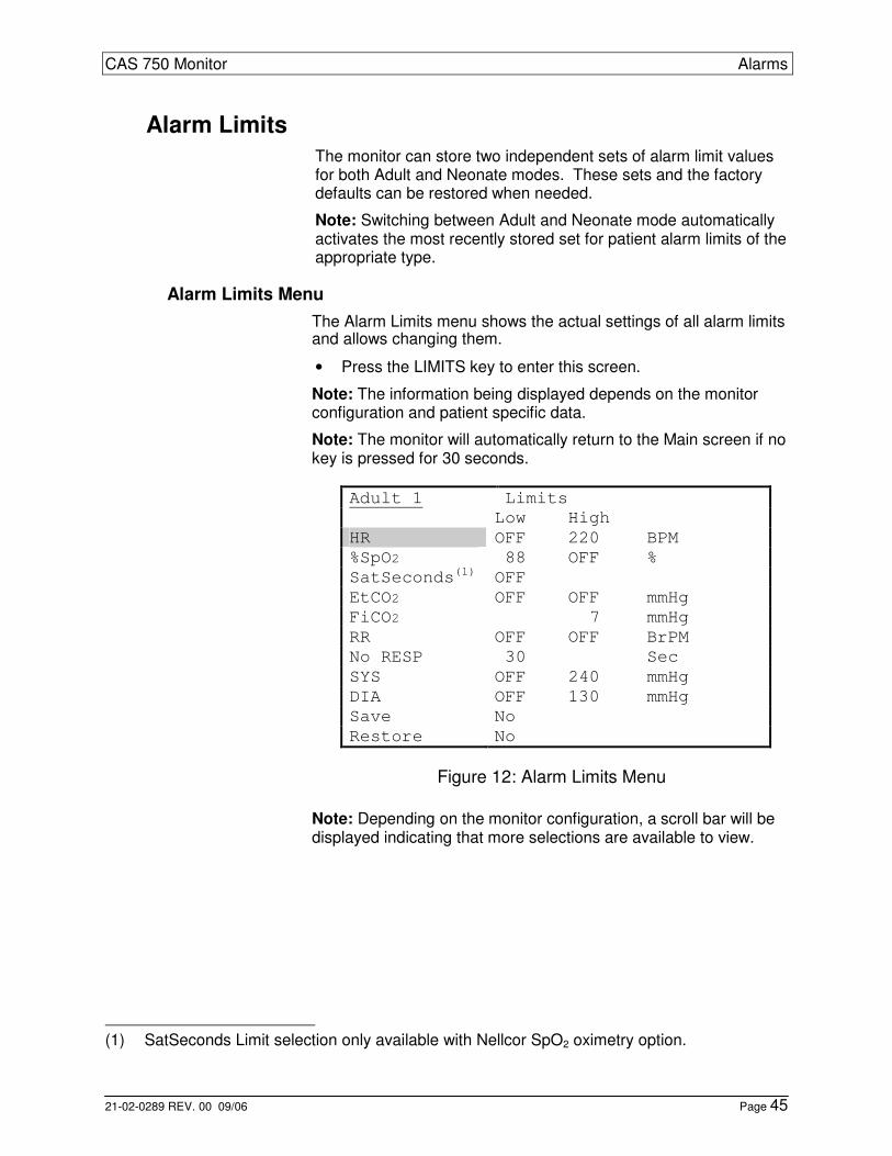
The Alarm Limits menu shows the actual settings of all alarm limits and allows changing them.
• Press the LIMITS key to enter this screen.
Note: The information being displayed depends on the monitor configuration and patient specific data.
Note: The monitor will automatically return to the Main screen if no key is pressed for 30 seconds.
Adult 1 Limits
Low High
HR OFF 220 BPM
%SpO2 88 OFF %
SatSeconds(1) OFF
EtCO2 OFF OFF mmHg
FiCO2 7 mmHg
RR OFF OFF BrPM
No RESP 30 Sec
SYS OFF 240 mmHg
DIA OFF 130 mmHg
Save No
Restore No
Figure 12: Alarm Limits Menu
Note: Depending on the monitor configuration, a scroll bar will be displayed indicating that more selections are available to view.
(1) SatSeconds Limit selection only available with Nellcor SpO2 oximetry option.

Alarms CAS 750 Monitor
Page 46 21-02-0289 REV. 00 09/06
Changing Alarm Limits
The cursor is automatically positioned at the first item in the left column.
• Use the UP and DOWN keys to select the alarm limit that needs to be changed.
• Use the NEXT key to scroll to the next “Low” column or ad-vance to the “High” column by pressing the key again.
• Use the UP or DOWN keys to increase or decrease the alarm limit value.
Note: Several changes may be done in one session. Use the PREVIOUS key to move the cursor back to the left column and re-peat the steps as before.
• Press the RETURN key when finished.
The monitor returns to the Main screen, all changes will become effective immediately and remain valid until the monitor is turned off.
Saving Alarm Limits
To save the alarm limit changes, proceed as follows:
• Use the DOWN key and move the cursor to the “Save” posi-tion.
• Use the NEXT key and move the cursor to the “No” position.
• Use the UP or DOWN keys and select the appropriate alarm limit set “Adult 1” or “Adult 2” for saving.
Note: Saving options will be “Neo 1” and “Neo 2” when the monitor is in Neonate mode.
• Press the LIMITS key to start the saving process.
The message “Saving” appears and the alarm limit values will be stored in memory.
If a second set of alarm limits is required, repeat these steps and save the changes under a different name (e.g. “Adult 2” or “Neo 2”).
• Press the RETURN key when finished.
The monitor returns to the Main screen, all changes will become effective immediately and remain valid until alarm limits changed manually or a different set of alarm limits is selected.

CAS 750 Monitor Alarms
21-02-0289 REV. 00 09/06 Page 47
Restore Alarm Limits
To restore a set of alarm limits, proceed as follows:
• Use the DOWN key and move the cursor to the “Restore” posi-tion.
• Use the NEXT key and move the cursor to the “No” position.
• Use the UP or DOWN keys and select the appropriate alarm limit set “Factory Default”, “Adult 1” or “Adult 2” to restore.
Note: Restore options will be “Factory Default”, “Neo 1” and “Neo 2” when the monitor is in Neonate mode.
• Press the LIMITS key to start the restore process.
The message “Restoring” appears and the alarm limit values are overwritten with the restored values.
• Press the RETURN key when finished.
The monitor returns to the Main screen and the new limit set will become effective immediately.
Factory Default Alarm Limits
Factory Default Alarm Limits are different for Adult and Neonatal patients.
Adult Neonate
Parameter Low High Low High
Heart Rate OFF 220 OFF 220
%SpO2 88 OFF 88 96
Pulse Rate OFF 220 OFF OFF
SatSeconds OFF N/A OFF N/A
EtCO2 OFF OFF OFF OFF
FiCO2 N/A 7 N/A 5
Resp Rate OFF OFF OFF OFF
No Resp 30 N/A 20 N/A
Systolic OFF 240 OFF 120
Diastolic OFF 130 OFF 80
Table 1: Factory Default Alarm Limits

Alarms CAS 750 Monitor
Page 48 21-02-0289 REV. 00 09/06
Alarm Volume
The alarm tone volume can be changed but not completely turned off.
• To change the alarm tone volume follow the steps described in paragraph “Audio/Visual Menu” on page 41.
Alarm Delays
To reduce the number of false-positive alarms, some patient alarms will be activated after a short delay. These are:
• Heart Rate alarms: 5 seconds
• EtCO2 alarms: 10 seconds
• FiCO2 alarm: 10 seconds
• RR alarms: 10 seconds
When the monitor incorporates Nellcor SpO2:
• %SpO2 alarms: 0 or SatSeconds (configurable)
To change the alarm delay, follow the steps described in para-graph “Changing Alarm Limits” on page 46.
• SpO2 Pulse Rate alarms: 0 or 10 seconds (configurable)
To change the alarm delay, follow the steps described in para-graph “Selecting Alarm Delay” on page 95.
When the monitor incorporates Masimo SpO2:
• %SpO2 and Pulse Rate alarms: 0 or 10 seconds (configur-able)
To change the alarm delay, follow the steps described in para-graph “Selecting Alarm Delay” on page 95.
Note: All other alarms are generated without any delay.
CAS 750 Monitor Alarms
21-02-0289 REV. 00 09/06 Page 49
Stand By mode (750S)
This mode can be used just prior to connecting the monitor to a patient, but all the monitor’s cables are connected.
Press and holding for two (2) seconds the SILENCE/RESET pushbutton.
When enabled, all Equipment alarms are silenced and the mes-sage “Stand By” is displayed on the Main display.
For the Stand by feature to work properly, the following conditions must apply;
The monitor cannot be actively monitoring any patient parameter.
To return the monitor to normal operation, connect the SpO2 finger probe to the patient or press the NIBP pushbutton key.

Alarms CAS 750 Monitor
Page 50 21-02-0289 REV. 00 09/06
This page is intentionally left blank

CAS 750 Monitor ECG/Resp
21-02-0289 REV. 00 09/06 Page 51
4 ECG/Resp
ECG and Respiration
Introduction
This section describes the ECG and Respiratory monitor function. Both, the ECG signal and the respiratory signal (based on the tho-rax impedance change) are measured through the same set of ECG electrodes.
The monitor automatically detects whether a 3-lead or a 5-lead pa-tient cable is connected and allows the user to make ECG lead se-lections accordingly.
The CAS 750 Monitor determines respiration by impedance pneumography. Patient respiration is achieved by applying a low voltage, high frequency AC signal across the active ECG leads (LA/L and RA/R). The monitor detects changes in thoracic imped-ance that occur as a result in chest movements. Impedance nor-mally increases with inspiration and decreases with expiration. Respiration detection is based on an inspiration and an expiration. After an inspiration is detected, an expiration must be detected within 3 seconds (Neonate mode) or 5 seconds (Adult mode) to be counted as a breath.
Note: Special considerations are required for patients with pace-maker. Refer to paragraph “Monitoring Pacemaker Patients” on page 57.
Safety
Warning: If uncertain about the accuracy of any measurement, check the patient’s vital signs by alternate means and then make sure the monitor is functioning correctly.
Warning: Even though the ECG patient circuit is electrically iso-lated, it has not been designed for direct application on a patient’s heart.
Warning: The monitor is not detecting arrhythmias and is not alarming on irregular ECG rhythms.
Caution: ECG electrodes are contraindicated for use on patients with limited skin access or allergic reaction to electrode adhesive or application gel.

ECG/Resp CAS 750 Monitor
Page 52 21-02-0289 REV. 00 09/06
Caution: Reusable ECG electrodes are contraindicated for use for prolonged periods of use. It is not intended for long term monitor-ing. Electrodes must be removed and repositioned if indicated by skin integrity, and reapplied to a different monitoring site.
Caution: Do not rely on the ECG waveforms for any diagnostic purposes.
Preparations
Caution: Prior to patient monitoring, ensure the monitor is config-ured to the appropriate patient mode – Neonate or Adult. Refer to paragraph “Selecting Patient Mode” on page 92.
Note: The quality of ECG information is a direct result of the qual-ity of the electrical signal received at the electrode.
Note: Proper skin preparation is necessary for good signal quality at the electrode. A good signal at the electrode provides the moni-tor with valid information for processing the ECG data.
Note: Always check the Date Code of the electrodes prior to ap-plying them to the patient.
Note: Do not use the 5-Lead Patient Cable for 3-Lead monitoring. A “Leads OFF” message would be displayed.
Skin Preparation
The following is a suggested guideline for skin preparation and should be followed for all electrode types.
• Choose flat, non-muscular areas to place electrodes.
• Make sure the skin area where the electrodes are to be placed is clean, dry, intact and free of powder, oil or lotion.
• If necessary, shave hair from skin at chosen sites.
• Using a dry washcloth, gently rub skin surface at sites to re-move dead skin cells.
• Using a washcloth, thoroughly cleanse the site with a mild soap and water solution. Be sure to remove all oily residue, dead skin cells, and abrasives. Leftover abrasion particles can be a source of noise (artifact).

CAS 750 Monitor ECG/Resp
21-02-0289 REV. 00 09/06 Page 53
Electrode Placement
Special consideration may be required if the ECG electrodes are used to detect respiration. Follow the guidelines given in para-graph “Electrode Placement for Respiration” on page 55.
Note: When using “snap” leadwires, attach leadwires to elec-trodes first then apply electrodes to the patient. This prevents the gel from spreading and becoming ineffective as you attach the snaps to the electrodes.
3-Leadwire Electrode Placement
The lead wires that attach to the electrodes are color coded for ease of identification.
3-Lead AAMI Standard 3-Lead IEC Standard
LA = black (left arm) L = yellow (left arm)
RA = white (right arm) R = red (right arm)
LL = red (left leg) F = green (foot)
Table 2: 3-Lead Color and Coding The two active electrodes (left and right arm) should be placed on the patient’s thorax as shown in the following picture. The third electrode (left leg) is a reference electrode allowing for better sig-nal detection.
Figure 13: Adult and Neonatal Electrode Placement

ECG/Resp CAS 750 Monitor
Page 54 21-02-0289 REV. 00 09/06
5-Leadwire Electrode Placement
The lead wires that attach to the electrodes are color coded for ease of identification.
5-Lead AAMI Standard 5-Lead IEC Standard
LA = black (left arm) L = yellow (left arm)
RA = white (right arm) R = red (right arm)
RL = green (right leg) N = black (neutral)
LL = red (left leg) F = green (foot)
V = brown (common) C = white (chest)
Table 3: 5-Lead Color and Coding
Figure 14: 5-Lead Placement
The placement of the common V/C electrode is described in the following:
1) Fourth intercostals space to the right of the sternum
2) Fourth intercostals space to the left of the sternum
3) Directly between leads 2 and 4
4) Fifth intercostals space at midclavicular line
5) Level with 4 at left anterior auxiliary line
6) Level with 5 at left midaxillary line

CAS 750 Monitor ECG/Resp
21-02-0289 REV. 00 09/06 Page 55
Respiration Monitoring
Warning: Impedance respiration monitoring is not reliable when ECG electrodes are placed on the limbs.
Warning: The monitor may not detect all episodes of inadequate breathing, nor does it distinguish between central, obstructive and mixed apnea events.
Caution: Respiration monitoring is contraindicated for patients who are receiving high frequency ventilation assistance.
Several considerations have to be made when the patient’s respi-ration is monitored.
Electrode Placement for Respiration
Electrode placement is crucial to monitoring respiration by the im-pedance method. The sensitivity of the monitor and its ability to accurately detect respiration is greatly enhanced or impeded by the quality of the electrodes and optimal electrode placement.
Note: The respiration signal is received from the LA/L and RA/R electrodes. These leads are available on 3-lead and 5-lead ca-bles.
• Observe the patient and place the electrodes where the great-est breathing movement occurs on the chest.
Note: Should Respiration monitoring be difficult due to lead placement or too much motion artifacts, the Respiration function can be turned off. Refer to paragraph “Parameters Menu” on page 40.
Note: If CO2 monitoring is active, the Respiration Rate Alarm value will be determined from the CO2 measurement.

ECG/Resp CAS 750 Monitor
Page 56 21-02-0289 REV. 00 09/06
CVA Filter
Since impedance monitors are very sensitive to chest wall move-ments, the possibility of mistaking changes due to cardiac activity exists. A Cardiovascular Artifact (CVA) filter prevents apnea epi-sodes from being missed due to cardiogenic artifact. The CVA fil-ter simultaneously monitors the frequency of both the cardiac and respiratory signals. When enabled any deflections in the respira-tory waveform that occur at the same frequency as the ECG or higher are filtered out before the monitor sends the signal to the breath detector. Refer to paragraph “Selecting CVA Filter” on page 95.
Breath-Weighting
Note: The Breath-Weighting functionality is automatically active when the monitor is in Neonate mode, it cannot be disabled.
Note: Breath-Weighting is not applied when the monitor is in Adult mode.
A “No RESP” alarm is generated if the next breath does not occur before a specified time limit (e.g. 30 seconds) is exceeded. The monitor uses an internal timer to accomplish this.
With each breath detected, a five seconds amount is subtracted from the timer, instead of resetting it directly to zero. This is called Breath-Weighting. It avoids that a single - perhaps artificial - breath is resetting the timer to zero - and by doing so – delaying or omitting a “No RESP” alarm.
The counter is only reset to zero when two breaths are detected within five seconds. For example: With breathweighting, a single gasp 18 seconds into a No RESP (assuming a No RESP delay time of 20 seconds), will delay the detection of the alarm by five seconds; without breathweighting, the No RESP timer would have been reset to zero and the No RESP alarm would have been de-layed by 18 seconds.
Note: Breath-Weighting may cause a “No RESP” alarm with a pa-tient connected to a ventilator and/or a respiration rate less than 10 to 15 breaths per minute.

CAS 750 Monitor ECG/Resp
21-02-0289 REV. 00 09/06 Page 57
ECG/Respiration Monitoring
Once the electrodes have been attached to the patient, proceed as follows:
• Connect the lead wires to the ECG patient cable, matching the colored end of the lead wire to the corresponding color on the cable.
Warning: Keep patient cables and lead wires away from the pa-tient’s neck area to avoid entanglement and accidental strangula-tion.
• Connect the round end of the ECG patient cable to the ECG/RESP connector on the side panel of the monitor.
• Press the POWER key to turn on the monitor.
• Select the appropriate ECG lead to be displayed on the Main screen. To optimize Respiration monitoring, Lead I configura-tion yields the most desirable results when the largest chest movements can be detected.
• If necessary, select the ECG and Respiration waveforms to be displayed on the Main Screen.
• Verify the signal quality with the help of the displayed ECG and Respiration waveforms.
• Wait for the monitor to determine the initial Heart Rate and Respiration Rate values. If the heart and lung visual indicators do not correspond to the patient’s heart/respiration rate, repo-sition the electrodes until the indicators flash in synch with the patient’s heartbeat and breathing. This will help to minimize false alarms.
• Check the Alarm Limits and configure them appropriately for the patient.
Monitoring Pacemaker Patients
Warning: Keep pacemaker patients under close observation. Heart Rate determination may continue to count the pacemaker rate during cardiac arrest and some arrhythmias. Therefore, do not rely entirely on Hear Rate alarms.
Warning: False low heart rate indicators or false asystole calls may result with certain pacemakers because of electrical over-shoots.

ECG/Resp CAS 750 Monitor
Page 58 21-02-0289 REV. 00 09/06
Note: ECG monitoring with patients on non-invasive transcutane-ous pacemakers may not be possible due to large amounts of en-ergy produced by these devices. Monitoring ECG with an external device may be needed.
To monitor a patient with a pacemaker, proceed as follows:
• Activate the pacemaker detection function as described in paragraph “Pacemaker Detection” on page 95.
• Follow institutional standards and change lead configuration as required.
When the monitor has detected a pacemaker pulse, it is rejected from being counted as a heartbeat. An artificial pulse is added to the ECG waveform display and the letter “P” is displayed to the right of the heartbeat icon to indicate the pacemaker discharge.
Note: Electrodes may need to be repositioned to modify detection of the electrical signals generated by a pacemaker.
Disconnection of Lead Wires and Patient Cable
To remove lead wires from a patient cable, always grasp the strain relief plastic portion of the lead wire. Do not pull the wire itself.
Figure 15: Detaching the Lead Wires

CAS 750 Monitor ECG/Resp
21-02-0289 REV. 00 09/06 Page 59
To remove the patient cable from the monitor’s ECG/RESP con-nector, press and hold down on the release button to unlock the cable and pull straight back. Do not pull on the cable itself.
Figure 16: Detaching the Patient Cable
ECG/Respiration Display Window
Heart Rate (HR) and Respiration Rate (RR) are displayed in the green window at the top right area of the Main screen. Note: When CO2 is enabled, the RR numeric value will be smaller in size indication it being a secondary parameter.
ECG/Respiration related Settings
Access the Parameters Menu as described on page 40 to review or change the following settings:
• ECG Lead selection
• ECG Trace Speed selection
• ECG Gain (sensitivity)
• Respiration Trace Speed selection
• Respiration selection (On or Off) Access the Alarm Limits Menu as described on page 45 to review or change the following settings:
• ECG Alarm Limits
• Respiration Alarm Limits
Note: If either of the Heart Rate Alarm Limit values is set to OFF, an Alarm Off bell icon is displayed to the right of the heart beat icon.
ECG/Resp CAS 750 Monitor
Page 60 21-02-0289 REV. 00 09/06
Access the Audio/Visual Menu as described on page 41 to review or change the following settings:
• Beep Source (ECG or SpO2)
• Beep Volume Access the monitor configuration (refer to section “Setup” starting on page 91) to change the following settings:
• Pacer Detection selection (On or Off)
• CVA Filter selection (On or Off)
ECG/Respiration Troubleshooting
ECG/Respiration related Messages
The following ECG related messages may occur and be displayed in place of the ECG trace:
ECG Error
A communication failure occurred on the ECG Board. The monitor needs to be serviced.
• Press the ALARMS key. The monitor silences the audio alarm tone, but the visual messages remain.
ECG Module
A failure occurred on the ECG Board. The monitor needs to be serviced.
• Press the ALARMS key. The monitor silences the audio alarm tone, but the visual messages remain.
Leads OFF
The electrodes may be disconnected from the patient or dried out. A lead wire or the patient cable may be disconnected or broken.
• Press the ALARMS key. The monitor silences the audio alarm tone, but the visual messages remain.
• Reconnect electrodes to patient
• Use a new set of electrodes
• Make sure the lead wires are connected securely.
• Make sure the patient cable jack on the monitor is plugged in securely.
• Replace the lead wires or patient cable if necessary.

CAS 750 Monitor SpO2
21-02-0289 REV. 00 09/06 Page 61
5 SpO2
Pulse Oximetry
Introduction
The Pulse Oximeter parameter (SpO2) determines arterial oxyhe-moglobin saturation by measuring the absorption of red and infra-red light passing through the tissue. Changes in absorption caused by pulsations of blood are used to determine Arterial Satu-ration (%SpO2) and Pulse Rate (PR).
If SpO2 was not selected as a trace to be displayed, a SpO2 signal bar graph will be displayed indicating the relative signal strength and signal quality at the sensor site.
Note: The bar graph indicator is not proportional to the pulse vol-ume.
An audio “beep” can be enabled that is generated each time the SpO2 module detects a pulsation.
Safety
Warning: If uncertain about the accuracy of any measurement, check the patient’s vital signs by alternate means and then make sure the monitor is functioning correctly.
Warning: Accurate oxygen saturation measurements cannot be obtained when the oximeter is not measuring the pulse properly. If the SpO2 waveform, perfusion bar graph or the Pulse Rate be erratic or inaccurate, first examine the patient for any sign of dis-tress and only then re-examine sensor placement.
Warning: A pulse oximeter should be considered an early warning device. As a trend toward patient deoxygenation is indicated, blood samples should be analyzed by a laboratory co-oximeter to completely understand the patient’s condition.
Warning: Various patient or mechanical conditions may cause in-accurate measurements. These conditions include but are not limited to: venous pulsations, hypotension, severe vasoconstric-tion, severe anemia, hypothermia, shock, cardiac arrest, sensor tension, sensor placement on the same extremity as a blood pres-sure cuff, arterial catheter or intravascular line, or arterial occlu-sion proximal to the sensor.
Warning: MRI Scanning - Do not use Nellcor oximetry sensors during magnetic resonance imaging (MRI) scanning. Conducted current could cause burns.

SpO2 CAS 750 Monitor
Page 62 21-02-0289 REV. 00 09/06
Warning: Do not expose probe detector to strong ambient light while monitoring a patient. A poor signal may result.
Warning: If a probe is damaged in anyway, discontinue use im-mediately.
Caution: Cardiogreen and other intravascular dyes, depending on the concentration, may affect the accuracy of the oximeter meas-urement.
Caution: Significant levels of dysfunctional hemoglobins such as carboxyhemoglobin or methemoglobin may affect the accuracy of the measurement.
Caution: Certain antibiotics, such as the Sulfas, can create high levels of methemoglobin. Methemoglobin is unable to bind O2 and will absorb light similarly to reduced hemoglobin, thus giving an ar-tificially low SpO2.
Caution: Reusable SpO2 sensors - Prolonged monitoring may re-quire changing the probe site periodically. The sensor must be removed and repositioned every 4 hours and if indicated by circu-latory condition or skin integrity, reapplied to a different monitoring site.
Caution: Disposable SpO2 sensors - Prolonged monitoring may require changing the probe site periodically. The sensors must be removed and repositioned every 8 hours and if indicated by circu-latory condition or skin integrity, reapplied to a different monitoring site. This sensor type should not be used with patients that exhibit allergic reactions to adhesive tape.
Caution: Masimo LNOP probe - Tissue damage can be caused by incorrect application or use of an LNOP probe, for example by wrapping the probe too tightly. Inspect the probe site as directed in the probe’s directions for use to ensure skin integrity and correct positioning and adhesion of the probe.
SpO2 Sensors
The monitor can be equipped to use SpO2 sensors manufactured by Masimo or Nellcor. The appropriate manufacturer’s logo is shown next to the SpO2 input connector.
Note: No other manufacturer’s sensors should be used.
Select a sensor based on the patient size and monitoring condi-tions and properly attach the sensor to the patient.
Note: Consult instructions enclosed with each sensor for proper application.
There are a variety of SpO2 sensors designs for a specific clinical application. Please refer to the Instructions of Use, which are sup-plied with each type of sensor.

CAS 750 Monitor SpO2
21-02-0289 REV. 00 09/06 Page 63
Preparations
Follow the instructions provided by the sensor manufacturer (Ma-simo or Nellcor) and prepare for SpO2 monitoring as follows:
• Select a sensor that has the appropriate size for the patient’s digit or extremity.
• Clean the surface of the probe before and after each patient use.
• Correctly position and attach the probe to the patient.
• Connect the sensor cable to the SpO2 patient cable.
• Verify a secure connection and gently tug on the patient cable connector.
• Plug the SpO2 patient cable into the SpO2 connector on the left side panel of the monitor.
Note: The SpO2 probe must be kept as motionless as possible to make a proper determination. To minimize motion artifacts, se-cure the sensor cable independently from the sensor. Tape may be used to secure the cable to the patient, e.g. around the base of the finger. Make sure that the tape being used does not restrict the blood flow.
SpO2 Monitoring
Once the sensor has been attached to the patient and the cable to the monitor, proceed as follows:
• Press the POWER key to turn the monitor on.
• If required, configure the appropriate waveform to be displayed on the Main Screen.
• Verify the signal quality and strength with the help of the SpO2 waveform or the bar graph indicator.
• Wait for the monitor to determine the initial %SpO2 and Pulse Rate values.
Caution: Some sensors may not be appropriate for a particular patient. If at least ten seconds of one bar pulses cannot be ob-served for a given sensor, change sensor location or sensor type until this condition is achieved.
• Check the alarm limits and configure them appropriately for the patient.

SpO2 CAS 750 Monitor
Page 64 21-02-0289 REV. 00 09/06
Note: If SpO2 is selected as a waveform parameter, no bar graph indicator is displayed.
Note: Inspect the SpO2 sensor site every 2 to 4 hours or per hos-pital protocol. If there is any skin irritation caused by the sensor, remove the sensor and apply it to a different location.
SatSeconds™ Alarm Management
Note: The SatSeconds™ alarm management feature is only avail-able in monitors with Nellcor’s Oximax technology.
False or nuisance alarms are a common concern with pulse oxi-metry monitoring. Nuisance alarms are often triggered by minor and brief desaturation events that are clinically insignificant. Clini-cians tend to manage these alarms by ignoring them, turning off the alarm or monitor, or widening the alarm limits. The CAS 750 Monitor incorporates Nellcor’s SatSeconds Alarm Management feature that offers a better way to manage nuisance alarms with-out sacrificing patient safety.
The SatSeconds function can be activated from the Alarm Limits menu by selecting a SatSeconds limit, or “clock” of 10, 25, 50, 100 or OFF (0) SatSeconds. Clinicians who choose to employ the Sat-Seconds function should select a limit suited to their clinical envi-ronment and patient conditions. Think of SatSeconds as the prod-uct of magnitude and time a patient exceeds SpO2 alarm limits. For example, 3 points below the alarm limit for 10 seconds equals 30 SatSeconds. An alarm is only triggered if a desaturation event occurs that reaches the SatSeconds limit you selected. As a safety net, when three or more SpO2 alarm violations occur within 60 seconds, an alarm will sound even if the SatSeconds limit has not been reached. To activate the SatSeconds function, proceed as follows:
• Press the LIMITS key to enter the Alarm Limits menu.
• Use the DOWN key to select “SatSeconds”.
• Use the NEXT key to scroll to the next column to the right.
• Use the UP or DOWN keys to increase or decrease the Sat-Seconds value.
• Press the RETURN key when finished. All changes will be saved and become immediately effective.
Note: When SatSeconds is set to OFF, the alarm delay for %SpO2 is based on the current configuration. Refer to paragraph “Selecting Alarm Delay” on page 95.

CAS 750 Monitor SpO2
21-02-0289 REV. 00 09/06 Page 65
Disconnecting SpO2 Accessories
When SpO2 monitoring is not required, disconnect the patient ca-ble from the monitor by squeezing the tabs with your thumb and index finger while pulling the connector away from the monitor.
Note: To avoid damage to the Interface Cable, always hold it by the connector rather than the cable when connecting or discon-necting either end.
When the probe is disconnected from the monitor, an Equipment Alarm is activated and the message “No SpO2 Probe” appears. Press the ALARMS key to acknowledge the alarm.
SpO2 Display Window
Oxygen Saturation (%SpO2) and Pulse Rate (PR) are displayed in the yellow window at the lower right area of the Main screen.
Note: The bar graph indicator is only presented if the SpO2 wave-form is not displayed in one of the trace windows.
Note: When ECG is enabled, the PR numeric value will be smaller in size indication it being a secondary parameter.
SpO2 related Settings
Access the Parameters menu as described on page 40 to review or change the following settings:
• SpO2 Trace selection
• SpO2Trace Speed selection Access the Alarm Limits menu as described on page 45 to review or change the following settings:
• SpO2 Alarm Limits Access the Audio/Visual menu as described on page 41 to review or change the following settings:
• Beep Source (ECG or SpO2)
• Beep Volume
SpO2 CAS 750 Monitor
Page 66 21-02-0289 REV. 00 09/06
SpO2Troubleshooting
Note: If the accuracy of any measurement does not seem reason-able, first check the patient’s vital signs by an alternate method.
Note: The %SpO2 and related Pulse Rate numeric displays will show dashes “- - -“ and the signal strength window will be blank when no SpO2 probe is attached to the monitor.
Note: Inaccurate SpO2 measurements may be caused by:
• Anemia or low hemoglobin concentrations.
• Electro surgical interference.
• Excessive ambient light.
• Excessive patient movement.
• Incorrect sensor application or use.
• Intravascular dyes such as indocyanine green or methylene blue.
• Moisture in the sensor.
• Placement of a sensor on an extremity with a blood pressure cuff, arterial catheter, or intravascular line.
• Venous pulsations.
Note: The loss of a pulse signal can occur in any of the following situations:
• A blood pressure cuff is inflated on the same extremity as the one with the SpO2 sensor attached.
• Excessive ambient light such as from a surgical lamp, a bilirubin lamp, or sunlight is present.
• The patient has hypotension, severe vasoconstriction, severe anemia, or hypothermia.
• The patient is in cardiac arrest or is in shock.
• The sensor is too tight.
• There is arterial occlusion proximal to the sensor.
CAS 750 Monitor SpO2
21-02-0289 REV. 00 09/06 Page 67
SpO2 related Messages
Note: If SpO2 is selected as a waveform parameter, messages appear in the waveform area of the display. If SpO2 is selected as a numeric parameter, the messages appear in the Equipment Message Window of the display.
The following SpO2 related messages may occur:
Chk SpO2 Probe
Note: This message relates to Masimo technology only. The monitor is questioning the quality of the signal being received by the SpO2 probe or the probe is receiving too much ambient light.
• Press the ALARMS key. The monitor silences the audio alarm tone, but the visual messages remain.
• Verify that the probe being used is the correct one for the monitor’s SpO2 configuration.
• Replace a wrong or defective probe.
• Verify that the probe is being used according to the manufac-turer’s recommendations.
• Verify that the probe emitter and detector are parallel to and directly opposing each other.
Low Perfusion
Note: This message relates to Masimo technology only. The perfusion level being received by the SpO2 probe is low.
• Determine if an extreme change in the patient’s physiology and blood flow at the monitoring site occurred (e.g. an inflated blood pressure cuff, a squeezing motion).
• Try to warm the patient or the probe site.
• Move probe to a site with better perfusion.

SpO2 CAS 750 Monitor
Page 68 21-02-0289 REV. 00 09/06
Low Signal IQ
Note: This message relates to Masimo technology only. The quality of the signal level being received by the SpO2 probe is in question.
• Ensure proper probe type and application.
• Verify that the probe emitter and detector are parallel to and directly opposing each other.
• Clean or replace the probe.
Note: When the message “Low Perfusion” or “Low Signal IQ” ap-pear and the monitor is displaying valid %SpO2 numerics, no au-dible or visual alarms will be generated. In case the monitor is not displaying valid %SpO2 numerics, an audible and visual alarm will be generated.
No SpO2 Probe
The monitor is not detecting the SpO2 probe. The probe was dis-connected from either the Interface Cable or from the monitor.
• Press the ALARMS key. The monitor silences the audio alarm tone, but the visual messages remain.
• Reconnect probe to monitor.
Probe Error
The SpO2 probe being used is not the correct one for the monitor’s configuration.
• Press the ALARMS key. The monitor silences the audio alarm tone, but the visual messages remain.
• Verify the probe being used is the correct probe.
Pulse Search
The monitor is searching for a Pulse signal. This is normal at power-up as the monitor searches for a pulse or the probe position may have changed.
• Check the probe site.
SpO2 Error
A failure occurred on the SpO2 board. The monitor needs to be serviced.
• Press the ALARMS key. The monitor silences the audio alarm tone, but the visual messages remain.
CAS 750 Monitor SpO2
21-02-0289 REV. 00 09/06 Page 69
SpO2 Module
A failure occurred on the SpO2 board. The monitor needs to be serviced.
• Press the ALARMS key. The monitor silences the audio alarm tone, but the visual messages remain.
SpO2 Probe OFF
The monitor is no longer receiving a patient signal from the SpO2
probe. The probe is no longer in contact with the patient.
• Press the ALARMS key. The monitor silences the audio alarm tone, but the visual messages remain.
• Check if probe is properly applied to the patient.
• Check if probe cable is connected to extension cable.
• Check if cable is attached to monitor.
• Replace probe and/or cable.

SpO2 CAS 750 Monitor
Page 70 21-02-0289 REV. 00 09/06
This page is intentionally left blank

CAS 750 Monitor NIBP
21-02-0289 REV. 00 09/06 Page 71
6 NIBP
Non-Invasive Blood Pressure
Introduction
The Non-Invasive Blood Pressure (NIBP) parameter is using the oscillometric measurement technique. It automatically inflates an occluding cuff and then releases the cuff pressure step by step. It determines systolic, diastolic and mean arterial pressure. The NIBP function is suitable for neonatal, pediatric and adult patients.
Safety
Warning: If uncertain about the accuracy of any measurement, check the patient’s vital signs by alternate means and then make sure the monitor is functioning correctly.
Warning: Do not place the cuff on a limb being used for A-V fistu-las, intravenous infusion or on any area where circulation is com-promised or has the potential to be compromised.
Warning: When monitoring over an extended period of time, or at frequent intervals, periodically observe the patient’s limb to make sure that the circulation is not impaired for a prolonged period of time.
Warning: The position of subject, physiological condition and other factors affect the NIBP readings. Blood pressure and pulse rate can fluctuate greatly between measurements; the monitor cannot alert the user to changes in vital signs occurring between measurement cycles.
Warning: Occasionally, electrical signals at the heart do not pro-duce a peripheral pulse. If a patient’s beat-to-beat pulse ampli-tude varies significantly (for example, pulsus alternans, atrial fibril-lation, rapid-cycling artificial ventilator), blood pressure and pulse rate readings can be erratic and an alternate measuring method should be used for confirmation.
Warning: Do not apply external pressure against the cuff while monitoring. Doing so may cause inaccurate blood pressure val-ues.

NIBP CAS 750 Monitor
Page 72 21-02-0289 REV. 00 09/06
Caution: Always be sure to check that there are no signs of pro-longed impairment of circulation regardless of automatic safety features that restrict the over all measurement time.
Caution: In shock conditions, the low amplitude of the blood pres-sure waveform may make it difficult for the monitor to accurately determine the systolic and diastolic pressures.
Caution: The monitor does not operate effectively if a patient is having seizure activity, tremors or is connected to a heart/lung machine.
Caution: Consult a physician for interpretation of blood pressure measurements.
Caution: The pulse rate derived from an NIBP measurement may differ from the heart rate derived from the ECG waveform because the NIBP parameter measures actual peripheral pulses, not elec-trical signals or contraction from the heart.
Caution: As with any non-invasive oscillometric blood pressure monitor, the accuracy of the measurements obtained may be ad-versely affected by the presence of agents, which alter the pa-tient’s cardiovascular system.
Caution: Do not operate the monitor’s NIBP function unless it has been properly calibrated. Inaccurate blood pressure readings may result.
Caution: When a patient is experiencing arrhythmias during a measurement, the accuracy of the pulse determination may be af-fected or the time needed to complete a measurement may be ex-tended.
Caution: Do not alter the monitor's air hose. CAS Medical Sys-tems, Inc. cannot ensure proper monitor performance if the tubing is altered. Modification of the air hose will void the warranty. Avoid compression or restriction of pressure tubes.
Note: A patient’s vital signs may vary dramatically during the use of cardiovascular agents such as those that raise or lower blood pressure or those that increase or decrease heart rate.
Note: The maximum amount of time allowed completing a NIBP measurement is 120 seconds in Adult mode and 90 seconds in Neonate mode. If the measurement has not been completed within that time, the cuff is deflated automatically and a message is displayed indicating the problem.
Note: To prevent exposure of the extremity to an inordinately high pressure, the cuff is deflated automatically when the pressure in the system is greater than 290 mmHg in the Adult mode or 145 mmHg in the Neonate mode.
Note: In the event of a microprocessor failure, the cuff will be de-flated automatically within 10 seconds.

CAS 750 Monitor NIBP
21-02-0289 REV. 00 09/06 Page 73
Preparations
Patient Mode Selection
Caution: Prior to patient monitoring, ensure the monitor is config-ured to the appropriate patient mode – Neonate or Adult. Refer to paragraph “Selecting Patient Mode” on page 92.
Select the Neonate mode when measuring on newborn patients and for all babies where the systolic pressure is expected to be below 120 mmHg. Use the Adult mode for infant and adult pa-tients.
Switch from Neonate to Adult mode if one or more of the following conditions occur:
• Systolic pressure is expected to be above 120 mmHg.
• A cuff width of 6 cm or larger is required.
NIBP Hose Selection
Two different inflation hoses are available.
• The coiled ten-foot NIBP hose is recommended for adult and pediatric patients.
• The straight six-foot NIBP hose is recommended for neonatal patients and small infants.
Cuff Selection
The use of the correct size of cuff is essential for the accurate measurement of the blood pressure.
Note: CAS recommends the use of its reusable, disposable and neonatal cuffs.
Width: The widest cuff that can be placed around the upper arm or thigh should be used. A cuff that is too small for the arm will not supply sufficient pressure to the artery. This can cause an erro-neously high blood pressure reading.

NIBP CAS 750 Monitor
Page 74 21-02-0289 REV. 00 09/06
Length: The edge of the cuff is marked with a white arrow. It should fall within the white range marking when the cuff is applied to the patient. Otherwise the cuff is too long or too short.
Figure 17: Cuff Application Range Marker
Note: Overlapping the cuff will not affect the measurement results.
Cuff Application
Measurements made above the level of the heart will give reduced blood pressure readings while measurements made below the heart level will give increased readings. These errors are mainly due to the weight of the blood.
Figure 18: Cuff Application

CAS 750 Monitor NIBP
21-02-0289 REV. 00 09/06 Page 75
• When applying the cuff, make sure the cuff tubing is centered over the brachial artery.
• Wrap the cuff for a snug fit to avoid prolonged pumping time. Do not wrap a cuff over the patient’s clothing.
• Verify the hook and loop sections of the cuff are fully engaged when it is wrapped around the limb.
• The limb should be positioned to be at heart level.
• Do not compress the cuff or the cuff hose. The hose must not be kinked or pinched.
Warning: The cuff should not be applied on a limb being used for an intravenous infusion. Do not place the cuff on any extremity being used for SpO2 monitoring.
Note: Remember that there may be a marked difference between readings taken from the left and the right arms. Be consistent with each patient.
NIBP Measurements
Warning: Before using the monitor on a new patient, select the appropriate patient’s NIBP Initial Inflation cuff pressure.
Warning: When monitoring over an extended period of time, or at frequent intervals, periodically observe the patient’s limb to make sure that the circulation is not impaired for a prolonged period of time.
Caution: Make sure the monitor is set to the correct Patient Mode. Refer to page 32 or to paragraph “Selecting Patient Mode” on page 92 to change the patient mode.
Note: The cuff target pressure must be higher than the patient’s systolic pressure to obtain an accurate systolic and diastolic read-ing.
When the Initial Inflation Pressure (Init Inflate) is set to Adaptive, the initial cuff inflation pressure is 150 mmHg in Adult mode and 85 mmHg in Neonate mode. After the first measurement, the monitor will adapt the cuff inflation pressure automatically based on the previously measured systolic value (approximately 30 mmHg above). This will continue until the monitor is turned off and on again or the inflation pressure is selected manually.
When the Initial Inflation Pressure is set to any non-Adaptive set-ting, the initial cuff inflation pressure selection shall remain in af-fect until it is altered or when the Patient type is changed.
• To select an alternate Initial Inflation Pressure, enter the NIBP menu as described in this section on page 79.
• Select the desired “Init Inflate” pressure.

NIBP CAS 750 Monitor
Page 76 21-02-0289 REV. 00 09/06
• Return to the Main Screen by pressing the RETURN key. The selected Initial Inflation Pressure will be displayed in the NIBP window.
Note: The Initial Inflation Pressure setting is saved during a power cycle.
Caution: When measuring blood pressure on a pediatric patient using the Adult mode, it is recommended that the Initial Inflation Pressure be set to a lower value (e.g. 120 mmHg).
Once the cuff is selected and applied to the patient, proceed with the following steps:
• Connect the cuff to the end of the NIBP hose and make sure the hose is connected to the NIBP connector on left side of the monitor.
Starting a Blood Pressure Reading
Caution: Excessive motion can contribute to inaccurate meas-urements. It is important that the patient be kept still during a measurement. Make every attempt to alleviate patient’s fear, anxiety and pain.
Note: The NIBP key will start a NIBP measurement regardless of the type of screen that is currently displayed.
• Press the NIBP key to start a measurement.
The cuff inflation pressure will be displayed until the measurement is completed.
The measurement typically takes less than 30 seconds to com-plete. In no case will the cuff remain pressurized for more than 120 seconds for Adult/Pediatric patients and no more than 90 sec-onds for Neonates.
When the measurement is completed, the cuff will automatically deflate, the monitor will provide an audio indication and display the NIBP values: Systolic/Diastolic and (MAP) or Systolic/Diastolic and Pulse Rate.
Note: If any displayed NIBP measurement were to be left on the screen for up to 24 hours, the monitor will automatically blank the NIBP displays to all dashes “- - -“.
Stopping a Blood Pressure Reading
A blood Pressure Reading can be interrupted for any reason at any time.
• Pressing the NIBP key during an ongoing NIBP measurement will interrupt the measurement and immediately deflate the cuff.

CAS 750 Monitor NIBP
21-02-0289 REV. 00 09/06 Page 77
Entering the Cycle Mode
If a cycle time is selected the monitor will automatically take blood pressure measurements at pre-selected time intervals.
• Enter the NIBP Menu as described in this section on page 79.
• Select the desired “NIBP Cycle” time.
• Select an alternate Initial Inflation Pressure if necessary.
• Return to the Main Screen by pressing the RETURN key. The selected cycle time will be displayed in the NIBP window.
• Press the NIBP key to begin the first measurement.
Note: If the Initial Inflation Pressure was altered, the first meas-urement will be made using that setting. After the first measure-ment, the monitor will switch to the Adaptive mode and adapt the cuff inflation pressure automatically based on the previously measured systolic value (approximately 30 mmHg above).
The measurement results are displayed in the NIBP Numeric Area of the Main Screen until the end of the next Automatic measure-ment or the start of the next Manual measurement. The remaining time until the next measurement will be displayed as well.
Note: If a measurement is desired between measurement cycles, press the NIBP key. After this measurement, the monitor will con-tinue the Automatic Cycle mode.
Note: The Automatic Cycle mode is not saved during a power cy-cle.
Terminating the Cycle Mode
To return to the Manual NIBP mode, proceed as follows:
• Enter the NIBP Menu as described in this section on page 79.
• Change the “NIBP Cycle” entry back to Manual.
STAT Mode
The monitor will take a series of automatically started blood pres-sure measurements for a period of 5 minutes when STAT mode is activated. Each measurement is followed immediately by the next one after a 10 seconds pause that allows venous blood to return.
Warning: Readings obtained during STAT mode may not meet the stated accuracy of this monitor.

NIBP CAS 750 Monitor
Page 78 21-02-0289 REV. 00 09/06
Warning: In some cases, rapid, prolonged cycling of an oscil-lometric, noninvasive blood pressure monitor cuff has been asso-ciated with any or all of the following: ischemia, purpura, or neu-ropathy. Apply the oscillometric cuff appropriately, according to instructions, and check the cuff site and cuffed extremity regularly when blood pressure is measured at frequent intervals or over ex-tended periods of time.
Entering STAT Mode
To activate the STAT mode, proceed as follows:
• Enter the NIBP Menu as described in this section on page 79.
Note: The monitor must be in the Manual NIBP Cycle mode when selecting STAT mode.
• Select an alternate Initial Inflation Pressure if necessary.
• Move the cursor to STAT and then select ON.
• Return to the Main Screen by pressing the RETURN key. The message “STAT” appears in the NIBP window.
• Press the NIBP key to begin the first measurement.
Note: If the Initial Inflation Pressure was altered, the first meas-urement will be made using that setting. After the first measure-ment, the monitor will switch to the Adaptive mode and adapt the cuff inflation pressure automatically based on the previously measured systolic value (approximately 30 mmHg above).
Between readings, the NIBP window will display the remaining seconds until the next measurement.
Note: Selecting STAT mode will override any time interval se-lected for the NIBP measurement cycle.
Exiting STAT Mode
The monitor will stop the STAT mode automatically after 5 minutes and returns to the Manual NIBP mode.
• Press the NIBP key to terminate the current NIBP measure-ment.
• Enter the NIBP Menu as described in this section on page 79.
• Select STAT mode OFF.

CAS 750 Monitor NIBP
21-02-0289 REV. 00 09/06 Page 79
NIBP Display Window
The NIBP numeric values (SYS, DIA, MAP and/or Pulse Rate) are displayed in the blue window at the lower center of the Main screen.
NIBP Menu
To enter the NIBP Menu
Press and hold the NIBP key for 2 seconds to access the NIBP menu. The following screen will be displayed:
NIBP
NIBP Cycle Manual
Init Inflate Adaptive
STAT OFF
NIBP Numerics S/D (MAP)
Figure 19: NIBP Menu
Note: While in the NIBP menu and no key is pressed for 30 sec-onds, the monitor will automatically save all changes made and re-turn to the Main Screen.

NIBP CAS 750 Monitor
Page 80 21-02-0289 REV. 00 09/06
Menu Options
The NIBP menu allows the user to:
• Select the NIBP Cycle time. Available selections are: Manual, 1, 2, 3, 4, 5, 10, 15, 30, 60 or 90 Minutes.
• Select the Initial Inflation Pressure for the next NIBP meas-urement. Available selections are:
Neonate mode: Adaptive, 60, 80, 85, 100 or 120 mmHg Adult mode: Adaptive, 80, 100, 120, 140, 150, 160, 180 or 200 mmHg
• Select the STAT mode to be OFF or ON
• Select how the NIBP numerics are to be displayed in the NIBP display window. Available selections are: S/D (MAP), S/D (PR) or (MAP) S/D.
Operating the NIBP Menu
To change settings, proceed as follows:
• Use the UP and DOWN keys to select the desired row.
• Move the cursor to the right with the use of the NEXT keys.
• Use the UP and DOWN keys to select the desired function or setting.
NIBP related Settings
Access the Parameters menu as described on page 40 to review or change the following settings:
• NIBP History selection for Trace 3. Access the Alarm Limits menu as described on page 45 to review or change the following settings:
• NIBP Alarm limits

CAS 750 Monitor NIBP
21-02-0289 REV. 00 09/06 Page 81
NIBP Troubleshooting Note: If the accuracy of any measurement does not seem reason-able, first check the patient’s vital signs by an alternate method.
NIBP related Messages
• Pressing the ALARMS key will cause the following NIBP re-lated messages to be removed from the display and silence the audio alarm tone.
Air Leak
Air leak in the cuff, the NIBP hose or in the internal pneumatic sys-tem of the monitor.
• Check that the cuff/hose/monitor connection is secure.
• Check cuff for leaks. Do not use a known leaky cuff.
Appl Error
Neonate cuff is detected in Adult Mode.
• Check cuff. Replace cuff or change operating mode.
Flow Error
Stable cuff pressure cannot be maintained by the NIBP pneumatic system.
• Check the external tube for kinks.
• Perform a Pneumatic Pressure Check as described on page 108.
• Replace cuff.
Loose Cuff
Cuff applied too loosely.
• Check cuff for proper fit on patient.
Motion
There was too much extremity motion for the monitor to accurately complete the NIBP measurement in 120 seconds. Measurements can be obtained when there is limited extremity movement, but the measurement time may be extended.
• Restrain patient extremity motion.
NIBP Cal
Pressure calibration data corrupted within NIBP module. Pressure module needs recalibration. The monitor needs to be serviced.

NIBP CAS 750 Monitor
Page 82 21-02-0289 REV. 00 09/06
NIBP Error
A failure occurred on the NIBP board. The monitor needs to be serviced.
NIBP Module
A failure occurred on the NIBP board. The monitor needs to be serviced.
Over Press
Cuff pressure exceeded 290 mmHg in the Adult mode or 145 mmHg in the Neonate mode. Very rapid squeezing of the cuff can cause this error.
• Repeat the measurement.
• If this message repeatedly occurs during normal use, the monitor must be serviced.
Range Error
The systolic reading exceeds the measurement range of 255 mmHg in the Adult mode or 135 mmHg in the Neonate mode.
• Repeat measurement.
• If the message is displayed again, use another method to measure the patient’s blood pressure.
Signal Sat
Signal Saturation or motion pulses too strong.
• Repeat measurement. Limit patient activity; the arm must be still and/or relaxed.
Time Out
The monitor was unable to complete a measurement within 120 seconds in the Adult mode or 90 seconds in the Neonate mode. An extremely long measurement can be due to a loose cuff, high blood pressure, or monitor re-pumps.
• Repeat measurement.
• Try higher initial cuff pressure.
• If message consistently reappears try using another means to obtain patient's blood pressure.
Weak Signal
The monitor did not detect any pulses during a NIBP measure-ment.
• Check the fit of the cuff.
• Repeat measurement.

CAS 750 Monitor CO2
21-02-0289 REV. 00 09/06 Page 83
7 CO2
Capnography
Introduction
The monitor uses Microstream non–dispersive infrared (NDIR) spectroscopy to continuously measure the amount of CO2 during every breath. The amount of CO2 at the end of exhalation (EtCO2) and the Respiratory Rate (RR) are measured.
The CO2 measurement is intended for use in any environment where continuous, noninvasive monitoring is desired, including hospital and mobile use (when protected from excessive moisture such as direct rainfall). It is intended for use on adult, pediatric, and infant/neonatal patients. It is intended for use on intubated and non-intubated patients.
A CO2 library can be selected for educational viewing. Refer to paragraph “CO2 Library” on page 41.
Safety
Warning: If uncertain about the accuracy of any measurement, check the patient’s vital signs by alternate means and then make sure the monitor is functioning correctly.
Warning: When monitoring CO2 in the presence of flammable gases or anesthetics, such as high concentrations of oxygen or ni-trous oxide, connect the gas outlet to a scavenger system.
Warning: CO2 readings and respiratory rate can be affected by certain ambient environmental conditions, sensor application er-rors, and certain patient conditions.
Caution: Microstream consumables are latex free, non-sterile and non-pyrogenic.
Caution: During MRI scanning, the monitor must be placed out-side the MRI suite. When the monitor is used outside the MRI suite, CO2 monitoring can be implemented using the FilterLine XL.

CO2 CAS 750 Monitor
Page 84 21-02-0289 REV. 00 09/06
Preparations Caution: Prior to patient monitoring, ensure the monitor is config-ured to the appropriate patient mode – Neonate or Adult. Refer to paragraph “Selecting Patient Mode” on page 92.
Microstream CO2 Consumables
Note: The Microstream CO2 technology requires the use of Micro-stream consumables. No other manufacturer’s products should be used.
When choosing CO2 consumables for a particular patient, the fol-lowing should be considered:
• Intubated or non–intubated.
• Whether the patient is on mechanical ventilation.
• Duration of use.
• Patient’s size and weight
Caution: Before use, carefully read the Directions for Use that is enclosed with the Microstream consumable.
Caution: Microstream consumables are designed for single pa-tient use, and are not to be reprocessed.
Warning: Do not attempt to disinfect or flush the FilterLine as the monitor can be damaged.
Non-Intubated Application
For non-intubated patients the continuous gas sampling is taken from the patient’s nose and/or mouth. The following consumables are available:
• CapnoLine: Cannula with nasal patient adapter.
• Smart CapnoLine Oral Nasal Cannula – for use in procedural sedation. Also available with O2 delivery.
• CapnoLine H – for use in ICU for patients receiving hi–flow oxygen by mask or on long term CPAP or Bi-PAP. Also avail-able with O2 delivery.
• NIV–Line – for use under oxygen CPAP, Bi–PAP or NPPV mask and to avoid intubation during EMS transport.
Select the appropriate CapnoLine and connect it to the monitor before attaching it to the patient’s airway. Be sure to follow Micro-stream CO2 Consumables’ Directions for Use for proper connec-tion.

CAS 750 Monitor CO2
21-02-0289 REV. 00 09/06 Page 85
Caution: Loose or damaged connections may compromise venti-lation or cause an inaccurate measurement of respiratory gases. Securely connect all components and check connections for leaks.
Warning: Carefully route the CapnoLine to reduce the possibility of patient entanglement or strangulation.
Note: Ensure the CapnoLine is not twisted or crimped and the cannula tips are in the nostrils.
Note: If the CapnoLine includes an additional oxygen connection, connect the oxygen connector to the standard outlet.
Intubated Applications
For intubated patients the continuous gas sampling is taken from the Airway Adapter directly at the intubation tube. The following consumables are available:
• FilterLine set for non-humid environments.
• FilterLine H set for humid environments.
Select the appropriate FilterLine and connect it to the monitor be-fore attaching it to the patient’s airway. Be sure to follow Micro-stream CO2 Consumables’ Directions for Use for proper connec-tion.
Warning: When used with closed suction system, do not place the airway adapter between the suction catheter and endotracheal tube.
Caution: Loose or damaged connections may compromise venti-lation or cause an inaccurate measurement of respiratory gases. Securely connect all components and check connections for leaks.
Note: Ensure the consumable is not twisted or crimped.
Note: During nebulization or suction (when not using closed suc-tion system), in order to avoid moisture buildup and FilterLine oc-clusion, disconnect the Airway Adapter from the patient’s endotra-cheal tube.
CO2 Monitoring
Once the appropriate consumable has been applied to the patient, proceed as follows:
• Press the POWER key to turn the monitor on.
• If necessary, select the CO2 waveform to be displayed on the Main screen.

CO2 CAS 750 Monitor
Page 86 21-02-0289 REV. 00 09/06
Note: If CO2 was not selected as a trace to be displayed, a CO2 signal bar graph will be displayed indicating the relative signal strength and signal quality.
Note: While the CO2 module is initializing (typically 30 to 40 sec-onds) the monitor shall display the message “CO2 Warm-Up” and dashes “- - -“ will remain in the numeric section.
• Check that the monitor is accurately detecting the CO2 signal and wait for the monitor to determine the initial EtCO2 and Respiration Rate values.
• If the lung visual indicator is not corresponding to the patient’s respiration, reposition the sensor until the indicators flash in synch with the patient’s breathing. This will help to minimize false alarms.
Check the alarm limits and configure them appropriately for the patient. Refer to paragraph “Alarm Limits Menu” on page 45.
Removing the CO2 Consumables
When CO2 monitoring is no longer required, disconnect the con-sumable by carefully removing the connector from the CO2 input receptacle.
When the consumable is disconnected from the monitor, the mes-sage “EtCO2 OFF” is displayed, the Equipment Alarm LEDs are flashing and an audible alarm sounds, indicating a connection has been broken.
Note: If CO2 is selected as a waveform, messages appear in the CO2 waveform window - otherwise messages appear in the Equip-ment Message Window of the Main screen.
• To acknowledge the alarm, press the ALARMS key.
Caution: Dispose of Microstream consumables according to stan-dard operating procedures or local regulations for the disposal of contaminated medical waste.
CO2 Display Window
End Tidal CO2 (EtCO2) and Respiration Rate (PR) are displayed in the yellow window at the lower left area of the Main screen.
Note: The bar graph indicator is only presented if the CO2 wave-form is not displayed in one of the trace windows.

CAS 750 Monitor CO2
21-02-0289 REV. 00 09/06 Page 87
CO2 related Settings
Access the Parameters menu as described on page 40 to review or change the following settings:
• EtCO2 Trace selection
• EtCO2 Trace speed selection
• EtCO2 Scale selection
• EtCO2 Print selection
• EtCO2 Trace Type selection Access the Alarm Limits menu as described on page 45 to review or change the following settings:
• EtCO2 Alarm Limits Access the Monitor Setup menu as described on page 96 to change the following settings:
• EtCO2 Unit selection (mmHg, kPa or %).
CO2 Troubleshooting
Note: If the accuracy of any measurement does not seem reason-able, first check the patient’s vital signs by an alternate method.
CO2 related messages
• Pressing the ALARMS key will silence the audio alarm tone for the following CO2 related messages.
Blocked Line
The CO2 module has attempted to purge the line with no success.
• Disconnect the FilterLine.
• Check the FilterLine for kinks and/or blockages.
Cal EtCO2
The CO2 module’s calibration timer has reached zero hours.
• Perform a CO2 calibration check.
Clearing Line
The CO2 module has detected an occlusion and is attempting to purge the line.
• Check the FilterLine tube for kinks and/or blockages.

CO2 CAS 750 Monitor
Page 88 21-02-0289 REV. 00 09/06
Chk EtCO2 Flow
The CO2 module has detected a blockage in the exhaust port.
• Check the exhaust port and associated tubing for kinks and blockages.
EtCO2 Error
A failure occurred on the CO2 Board.
• To reset the CO2 board turn the monitor off and disconnect it from external power (AC Line or 12VDC). Remove the bat-tery, and then reconnect the battery and external power. Turn the monitor on.
• If the message remains, the monitor needs to be serviced.
EtCO2 Module
A failure occurred on the CO2 Board. The monitor needs to be serviced.
EtCO2 OFF
The CO2 module is no longer receiving a signal from the patient or the FilterLine is no longer connected to the monitor. The consum-able is no longer connected to the monitor.
• Press the ALARMS key. The monitor silences the audio alarm tone, but the visual messages remain.
• Check the external tubing for disconnections.
Service EtCO2
The CO2 module’s service timer has reached zero hours. The monitor will continue to function.
• Arrange for service as soon as possible.

CAS 750 Monitor TEMP
21-02-0289 REV. 00 09/06 Page 89
8 TEMP
Temperature
Introduction
The monitor is designed to work with Yellow Springs (YSI) Series 400 temperature probes.
• Core Temperature probes.
• Skin Temperature probes.
• Esphogeal/Rectal Temperature probes.
Safety Warning: If uncertain about the accuracy of any measurement, check the patient’s vital signs by alternate means and then make sure the monitor is functioning correctly.
Preparations
Note: Consult instructions enclosed with each sensor for proper application.
Refer to section “Temperature Accessories” on page 149 for Tem-perature probe types and order information.
Temperature Monitoring
To take a temperature measurement:
• Connect the probe to the Temperature Adapter cable.
• Connect the Adapter cable to the TEMP connector on the left side of the monitor.
• Press the POWER key to turn the monitor on.
• Check that the monitor is accurately measuring temperature when the value has been determined.
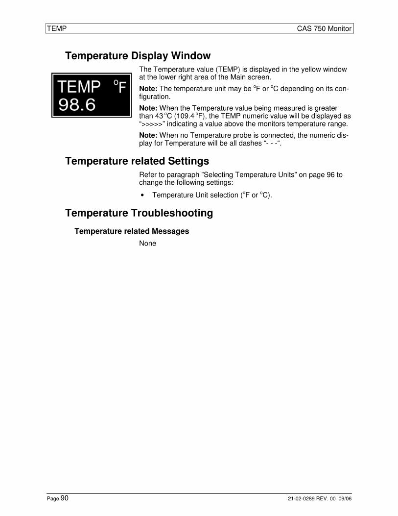
TEMP CAS 750 Monitor
Page 90 21-02-0289 REV. 00 09/06
Temperature Display Window
The Temperature value (TEMP) is displayed in the yellow window at the lower right area of the Main screen.
Note: The temperature unit may be oF or oC depending on its con-figuration.
Note: When the Temperature value being measured is greater than 43 oC (109.4 oF), the TEMP numeric value will be displayed as “>>>>>” indicating a value above the monitors temperature range.
Note: When no Temperature probe is connected, the numeric dis-play for Temperature will be all dashes “- - -“.
Temperature related Settings
Refer to paragraph ”Selecting Temperature Units” on page 96 to change the following settings:
• Temperature Unit selection (oF or oC).
Temperature Troubleshooting
Temperature related Messages
None

CAS 750 Monitor Setup
21-02-0289 REV. 00 09/06 Page 91
9 Setup
Configuring the Monitor
Entering the Setup Menu
The Setup menu shows all configuration options in a tabular form. To enter the Setup menu, proceed as follows:
• Press and hold the LIMITS and AUDIO/VISUAL keys while the monitor is being turned on.
Setup
Language English
Patient Adult
Audio Silence 2 Minute
Date 21-Mar-06
Time 11:26
DST OFF
Pacer Detect OFF
CVA Filter OFF
O2 Alarm Delay 10 Sec
EtCO2 Units mmHg
TEMP Units °F
Restore Default None
Background Dark
Figure 20: Setup Menu The cursor is automatically positioned at the first item in the left column.
• Use the UP and DOWN keys to select the item that needs to be changed.
• Use the NEXT key to move the cursor to the right column.
• Use the UP and DOWN key to scroll through the available op-tions.
• Press the RETURN key to exit the Setup menu.
Note: If no key is pressed for 60 seconds, the monitor automati-cally exits the Setup menu.
Note: Depending on the monitor configuration, a scroll bar will be displayed indicating that more selections are available to view.
All changes will be saved and the monitor returns to the Main screen.

Setup CAS 750 Monitor
Page 92 21-02-0289 REV. 00 09/06
Selecting the Language
To select the monitor’s language, proceed as follows:
• Enter the Setup menu as described on page 91 and follow the general instructions given there.
• Press one of the NEXT keys to move the cursor to the next column to the right.
• Use the UP or DOWN keys to select the desired language.
Note: Once a new language is selected, all text in the Setup menu (and in all other menus and screens) will be displayed in that lan-guage. This may cause difficulties if an unknown language is se-lected.
Selecting Patient Mode
Caution: Prior to patient monitoring, ensure the monitor is config-ured to the appropriate Patient mode.
To select the Patient mode, proceed as follows:
• Enter the Setup menu as described on page 91 and follow the general instructions given there.
• Press the DOWN key until the parameter “Patient” is selected.
• Press one of the NEXT keys to move the cursor to the next column to the right.
• Use the UP or DOWN keys to select Adult or Neonate mode.
Or alternatively:
• Keep the UP key pressed when the monitor is turned on to set the monitor to Adult mode.
• Keep the DOWN key pressed when the monitor is turned on to set the monitor to Neonate mode.
The Patient mode will be displayed in the Equipment Message Window in the lower left area of the Main screen.
Note: ECG, CO2, NIBP and Respiration functions are affected by selecting Adult or Neonatal operating modes. The factory default is the Adult mode.
CAS 750 Monitor Setup
21-02-0289 REV. 00 09/06 Page 93
Configure Audio Silencing
The audio signal associated with patient alarms can be silenced by pressing the ALARM key. The functionality of this key depends on the selected configuration:
To configure the monitor’s silencing function, proceed as follows:
• Enter the Setup menu as described on page 91 and follow the general instructions given there.
• Press the DOWN key until the parameter “Audio Silence” is selected.
• Press one of the NEXT keys to move the cursor to the next column to the right.
• Use the UP or DOWN keys to select the desired option.
Select “2 Minute” when the silence period should automatically terminate after 2 minutes.
Select “Permanent” when the silence period should continue per-manently until it is terminated manually.
Warning: In Permanent Silence mode the user is responsible to reactivating (enabling) the audio alarm signal by pressing the ALARMS key again.
Setting the Date
To set the monitor’s Date function, proceed as follows:
• Enter the Setup menu as described on page 91 and follow the general instructions given there.
• Press the DOWN key until the parameter “Date” is selected.
• Press one of the NEXT keys to move the cursor to Day-Month-Year.
• Use the UP or DOWN keys to increase or decrease the values for Day-Month-Year.
Note: Altering the monitors’ date will affect the History data.

Setup CAS 750 Monitor
Page 94 21-02-0289 REV. 00 09/06
Setting the Time
To set the monitor’s Time function, proceed as follows:
• Enter the Setup menu as described on page 91 and follow the general instructions given there.
• Press the DOWN key until the parameter “Time” is selected.
• Press one of the NEXT keys to move the cursor to Hours : Minutes.
• Use the UP or DOWN keys to increase or decrease the values for hours or minutes.
Note: Altering the monitors’ time will affect the History data.
Daylight Saving Time Option
To set the monitor’s Daylight Saving Time function, proceed as fol-lows:
• Enter the Setup menu as described on page 91 and follow the general instructions given there.
• Press the DOWN key until the parameter “DST” is selected.
• Press one of the NEXT keys to move the cursor to the next column to the right.
• Use the UP or DOWN keys to select on of the Daylight Saving Time options.
The possible options have the following meaning:
OFF: Daylight Saving Time is not activated. The monitor will not change the time automatically. It is up to the user for changing the time if needed. This is the monitor’s default setting.
N AMERICA: Use this setting and the monitor will automatically change time accordingly to the Daylight Saving Time for countries in North America.
EU 01:00: Daylight Saving Time for all European countries using Greenwich Mean Time.
EU 02:00: Daylight Saving Time for all European countries 1 hour ahead of Greenwich Mean Time.
EU 03:00: Daylight Saving Time for all European countries 2 hours ahead of Greenwich Mean Time.
Note: Enabling Daylight Saving Time will affect the History data.

CAS 750 Monitor Setup
21-02-0289 REV. 00 09/06 Page 95
Pacemaker Detection
To change the Pacemaker setting, proceed as follows:
• Enter the Setup menu as described on page 91 and follow the general instructions given there.
• Press the DOWN key until the parameter “Pacer Detect” is se-lected.
• Press one of the NEXT keys to move the cursor to the next column to the right.
• Use the UP or DOWN keys to select OFF or ON.
Selecting CVA Filter
To change the CVA Filter setting, proceed as follows:
• Enter the Setup menu as described on page 91 and follow the general instructions given there.
• Press the DOWN key until the parameter “CVA Filter” is se-lected.
• Press one of the NEXT keys to move the cursor to the next column to the right.
• Use the UP or DOWN keys to select OFF or ON.
Selecting Alarm Delay
To change the SpO2 Alarm Delay setting, proceed as follows:
• Enter the Setup menu as described on page 91 and follow the general instructions given there.
• Press the DOWN key until the parameter “O2 Alarm Delay” is selected.
• Press one of the NEXT keys to move the cursor to the next column to the right.
• Use the UP or DOWN keys to select 10 Sec or 0 Sec for the delay.

Setup CAS 750 Monitor
Page 96 21-02-0289 REV. 00 09/06
Selecting CO2 Units
To select the display unit for CO2 waveform and EtCO2 values, pro-ceed as follows:
• Enter the Setup menu as described on page 91 and follow the general instructions given there.
• Press the DOWN key until the parameter “EtCO2 Unit” is se-lected.
• Press one of the NEXT keys to move the cursor to the next column to the right.
• Use the UP or DOWN keys to select one of the options (mmHg, kPa or %).
Selecting Temperature Units
To select the display unit for Temperature values, proceed as fol-lows:
• Enter the Setup menu as described on page 91 and follow the general instructions given there.
• Press the DOWN key until the parameter “TEMP Unit” is se-lected.
• Press one of the NEXT keys to move the cursor to the next column to the right.
• Use the UP or DOWN keys to select ºC or ºF.
Selecting Monitor Set-Up Default
To select a preset set-up configuration mode, proceed as follows:
• Enter the Setup menu as described on page 91 and follow the general instructions given there.
• Press the DOWN key until the parameter “Restore Default” is selected.
• Press one of the NEXT keys to move the cursor to the next column to the right.
• Use the UP or DOWN keys to select one of the options (None, Factory or Sleep Study).
Note: When configured for Sleep Study, the “Auto Dim” shall be set to On and the “Audio Silence” shall be set to Permanent.
Refer to the paragraphs “Auto Dim” on page 42 and “Configure Audio Silencing” on page 93 for more information.

CAS 750 Monitor Setup
21-02-0289 REV. 00 09/06 Page 97
Selecting Display Background
To select the display background, proceed as follows:
• Enter the Setup menu as described on page 91 and follow the general instructions given there.
• Press the DOWN key until the parameter “Background” is se-lected.
• Press one of the NEXT keys to move the cursor to the next column to the right.
• Use the UP or DOWN keys to select Dark or Light.

Setup CAS 750 Monitor
Page 98 21-02-0289 REV. 00 09/06
This page is intentionally left blank

CAS 750 Monitor Cleaning
21-02-0289 REV. 00 09/06 Page 99
10 Cleaning
Warning: Do not, under any circumstances, perform any cleaning while the monitor is being used to monitor a patient. The monitor must be turned off. Unplug the monitor from the AC or DC power source and disconnect all accessories.
Caution: Do not open the monitor to clean it.
Caution: Do not immerse any part of the electrical connector of the cable or accessories in the cleaning or disinfection solution at any time. This may cause internal damage and reduce the product life.
Caution: Do not use abrasive cleaners, isopropyl alcohol or or-ganic solvent for cleaning. Use of these cleaners can cause dam-age, stiffness and brittleness to the monitors’ surface and to cables and wires.
Cleaning the Monitor
Caution: Disconnect all accessories from the monitor before cleaning.
Examine the monitor’s case for damages and check the AC power cord for bent or broken prongs, cracks or fraying. Neither the monitor nor the power cord should be used if damaged. If any damage is noted, contact the appropriate service personnel.
Caution: Do not spray or pour any water or cleaning solution di-rectly onto the monitor.
• Housing: As needed, clean the monitor using a soft cloth dampened with a mild dishwashing detergent solution and gently rub the soiled area until clean. Use a clean soft cloth to dry the monitor.
• Display: Clean the display window using a soft, lint-free cloth sprayed with an alcohol free glass cleaner. The use of paper towels is not recommended as it may scratch the surface.
• Disinfections: The monitor surfaces may be disinfected using a soft cloth saturated with a 10% (1:10) solution of chlorine bleach in tap water. When all of the surfaces have been disin-fected, wipe the entire surface of the monitor using a soft cloth dampened with fresh water to remove any trace amounts of residue and/or fumes.
Note: Thoroughly wipe off any excess cleaning solutions. Care should be taken to prevent water or cleaning solution to run into connector openings or crevices.

Cleaning CAS 750 Monitor
Page 100 21-02-0289 REV. 00 09/06
Cleaning Patient Cable and Leadwires
Prior to each patient use, inspect the patient cable and lead wires for damage.
• Clean the patient cable and lead wires using a soft cloth dampened with a germicidal solution.
Cleaning Cuffs and Pneumatic Hoses
Note: Refer to the product packaging for additional Cleaning and Disinfecting Instructions were applicable. Prior to each patient use, inspect the blood pressure cuff and the pneumatic hose for damage.
• Tuff-Cuff: Clean the cuff using a soft cloth dampened with a 70% Isopropyl Alcohol solution. The cuff should be allowed to thoroughly dry before use.
• Safe-Cuff: Clean the cuff using a soft cloth dampened with a soap, water-based detergent or chlorinated disinfectant solu-tion. Do not use alcohol.
• SoftCheck: These cuffs are designed for single patient use, and are not to be reprocessed.
• UltraCheck: For normal cleaning with mild detergents / dilute bleach solution (1-2%), wipe the cuff with the cleaning solu-tion, rinse with water and dry.
• Pneumatic Hose: Clean the pneumatic tubing using a soft cloth dampened with a germicidal solution.
Caution: If the cuff or hose should become grossly contaminated with blood or other bodily fluids, it should be discarded.
Note: It is not recommend submersing the cuff or hose. Liquid should not be permitted to enter the cuff bladder or hose because instrument damage may occur. Cuffs and hoses should be al-lowed to thoroughly dry before use.
Cleaning the SpO2 Interconnect Cable
Prior to each patient use, inspect the SpO2 Interconnect cable for damage.
• Clean the cable using a soft cloth dampened with a germicidal solution.

CAS 750 Monitor Cleaning
21-02-0289 REV. 00 09/06 Page 101
Cleaning SpO2 Sensors
Caution: Do not soak or immerse the sensor or its cable in any liq-uid solution. Do not attempt to sterilize it.
Refer to the Directions For Use pamphlet enclosed with each sen-sor for more information.
• Clean the SpO2 sensors with a soft cloth dampened with 70% Isopropyl alcohol solution. Allow the sensor to dry prior to placement on a patient.
Cleaning Temperature Probes
Refer to the Directions For Use pamphlet enclosed with each tem-perature probe for more information.
• Cleaned probe with a soft cloth dampened in mild detergent.
Disinfect probe if necessary:
• Use a soft cloth saturated with a 10% solution of chlorine bleach in tap water or 70% isopropyl alcohol.
• Wipe the entire surface with a soft cloth dampened with fresh water to remove any trace amounts of residue and/or fumes.
Cleaning CO2 Consumables
Microstream CO2 consumables are designed for single patient use and are not to be reprocessed.
Caution: Do not attempt to disinfect or flush the FilterLine as the monitor can be damaged.
Cleaning the Printer
Refer to the printer User’s Manual for more information.
Caution: Before cleaning the printer, disconnect the AC adapter.
• Wipe with a soft dry cloth.
To remove extreme dirt buildup:
• Soak a cloth with mild detergent, wring well and wipe. Dry by wiping with a soft dry cloth.
Caution: Do not use volatile chemicals such as thinner, benzine, etc.
Caution: Never wet the inside of the printer mechanism.

Cleaning CAS 750 Monitor
Page 102 21-02-0289 REV. 00 09/06
This page is intentionally left blank

CAS 750 Monitor Maintenance
21-02-0289 REV. 00 09/06 Page 103
11 Maintenance
Warning: Do not, under any circumstances, perform any testing or maintenance on the monitor while the monitor is being used to monitor a patient. The monitor must be turned off. Unplug the monitor from the AC or DC power source and remove the internal battery.
Caution: Service performed by unauthorized personnel could be damaging to the monitor and may void the war-ranty. For service, contact your CAS Representative.
Maintenance Intervals
Preventive maintenance of the monitor is an important function that should be performed routinely to ensure safe and efficient monitor operation. The following maintenance intervals are recommended:
• Battery Pack: Replace the battery every 2 years.
• ECG/Respiration: No user calibration is required. Perform a bench Test once a year or when there is doubt about the validity of the ECG and/or Respiration readings.
• SpO2: No user calibration is required. Perform a SpO2 Simulator Check once per year or when there is doubt about the validity of the SpO2 readings.
• NIBP: Perform a Pneumatic Pressure check every 6 months and a NIBP Calibration Check once a year or when there is doubt about the validity of the pressure readings.
• Temperature: No user calibration is required. Perform a Temperature Calibration Check once per year or when there is a doubt about the validity of the tempera-ture readings.
• CO2: Perform a CO2 Calibration Check once per year, after 4000 operating hours (whichever comes first) or when there is doubt about the validity of the CO2 read-ings. The monitor should be returned to CAS Medical Systems for periodic maintenance every 14,000 oper-ating hours.

Maintenance CAS 750 Monitor
Page 104 21-02-0289 REV. 00 09/06
Maintenance Checks
Entering the Service Menu
Warning: Do not enter the SERVICE menu when the monitor is connected to a patient.
To enter the monitor’s SERVICE menu, proceed as fol-lows:
• Press and hold the PARAMETERS and HISTORY keys while the monitor is being turned on.
Service
IrDA Test OFF
EtCO2 Check OFF
EtCO2 Cal OFF
EtCO2 CAL Date 06-Feb-04
EtCO2 S/N 00234
Service EtCO2 xxxxx Hours
Cal EtCO2 xxxx Hours
Manometer Mode OFF
Pneumatic Test OFF
PIC Voltage xx.xx v
Figure 21: Service Menu The cursor is initially positioned at the first item in the left column.
• Use the UP or DOWN keys to select any other item.
• Press one of the NEXT keys to move the cursor to the next column to the right.
• Use the UP or DOWN keys to scroll through the avail-able options.
Exiting the Service Menu
• Press the RETURN key to exit the menu and return to the Main screen.
Note: If no key is pressed for 15 minutes, the monitor will automatically return to the Main screen.

CAS 750 Monitor Maintenance
21-02-0289 REV. 00 09/06 Page 105
IrDA Test
The IrDA Test checks the alignment of the monitor and the printer to guarantee communication between their infrared windows.
To use the Infrared Test, proceed as follows:
• Enter the Service menu as described on page 104 and follow the general instructions given there.
• Change the IrDA Test setting from “OFF” to “ON”.
The message “Printing” will be displayed in the Equipment Message Window. When the Infrared windows are prop-erly positioned, the printer will begin to print a series of “A” characters. The test will continue for 60 seconds or can be terminated by the user.
• Press one of the PREVIOUS keys to cancel the test and return to the IrDA TEST menu selection.
CO2 Calibration Check
The CO2 Calibration Check is a tool to verify proper calibra-tion of the CO2 parameter.
Caution: Do not perform a CO2 Calibration Check when the monitor is in normal measuring mode. This mode cor-rects the CO2 value for BTPS (Body, Temperature, Pres-sure, Saturation), which assumes that alveolar gases are saturated with water vapor. The Calibration Check mode disables this correction.
Caution: The Calibration Check must be performed with a manufacturer authorized Calibration Kit containing (5% CO2, 21% O2, Balance N2) gas, tubing adapter and a cali-bration filter line. A manufacturer approved Calibration Kit can be purchased from Scott Medical (P/N 0304653ORFBD).
Note: The Calibration Check should be performed only af-ter the CO2 module has been operating for at least 20 min-utes in a normal operating mode.

Maintenance CAS 750 Monitor
Page 106 21-02-0289 REV. 00 09/06
To check CO2 Calibration, proceed as follows:
• Verify that the FilterLine supplied with the Calibration kit is firmly attached to the gas canister.
• Enter the Service menu as described on page 104 and follow the general instructions given there.
• Press the DOWN key until the parameter “EtCO2 Check” is selected.
• Press one of the NEXT keys to select the “OFF” set-ting.
• Change the EtCO2 Check setting from “OFF” to “Con-nect Gas”.
• Connect the FilterLine to the monitor.
• The highlighted section should read “Open 5% Gas”.
• When the message “Open 5% Gas” appears, press and hold open for 15 seconds the gas valve until the reading stabilizes.
• Verify the reading on the display to be 5.0% ± 0.3 vol%.
Note: Calibration is not required if the measured value are the same as the concentration of the calibration gas ± 0.3 vol%.
• Press one of the PREVIOUS keys to cancel the test and return to the EtCO2 Check menu selection.
• Disconnect the FilterLine from the monitor.
Should the monitor fail the EtCO2 Check, it is recom-mended to perform an EtCO2 Calibration or returning the monitor for service.
CO2 Calibration
Note: Perform the Calibration only after performing the Calibration Check.
Caution: The Calibration must be performed with a manu-facturer authorized Calibration Kit containing (5% CO2, 21% O2, Balance N2) gas, tubing adapter and a calibration FilterLine. A manufacturer approved Calibration Kit can be purchased from Scott Medical (P/N 0304653ORFBD).

CAS 750 Monitor Maintenance
21-02-0289 REV. 00 09/06 Page 107
To perform a CO2 Calibration, proceed as follows:
• Verify that the FilterLine supplied with the Calibration Kit is firmly attached to the gas canister.
• Enter the Service menu as described on page 104 and follow the general instructions given there.
• Press the DOWN key until the parameter “EtCO2 Cal” is selected.
• Press one of the NEXT keys to select the “OFF” set-ting.
• Change the EtCO2 Cal setting from “OFF” to “Connect Gas”.
• Connect the FilterLine to the monitor.
• The highlighted section should read “Open 5% Gas”.
• When the message “Open 5% Gas” appears, press and hold the gas valve until the message “Remove Gas” is displayed.
• The highlighted section should read “Passed” and two audible beeps should be heard when the calibration is completed.
• Verify the “EtCO2 CAL Date” and the “Cal EtCO2 Hours” have been updated.
The starting hours for Calibration are initially 1200 hours, and then 4000 after that. This timer is automatically reset to 4000 hours during the Calibration process as long as it has been more than 720 hours from the last calibration. If this was less than 720 hours, the timer does not reset.
• Press one of the PREVIOUS keys to cancel the test and return to the EtCO2 Cal menu selection.
• Disconnect the FilterLine from the monitor.
Note: Should the monitor fail the EtCO2 Calibration, it is recommended the procedure be repeated. Prior to repeat-ing the Calibration procedure, carefully check all connec-tions. Should the monitor continue not to pass the Calibration procedure, the monitor should be returned for service.

Maintenance CAS 750 Monitor
Page 108 21-02-0289 REV. 00 09/06
NIBP Checks
To guarantee correct NIBP measurements, it is recom-mended to perform the following checks at least once per year. All checks can be done in one session beginning with the Pneumatic Pressure Check, then continue with the Calibration Check and finally perform the Over Pressure Test.
Note: The monitor must be in the Adult mode to perform the following pressure checks.
The following equipment is required to perform the NIBP pressure checks:
• A Calibration Kit (P9) which is included with the moni-tor.
• A Mercury manometer or equivalent whose accuracy meets the AAMI/ANSI Standard for Non-Automated Sphygmomanometers, 2002.
Warning: Do not activate the Service menu when a cuff is attached to a patient.
Pneumatic Pressure Check
To perform the Pneumatic Pressure Check, proceed as fol-lows:
• Connect the NIBP inflation hose to the monitor without a cuff connected to the hose.
• Obtain the male luer plug from the Calibration Kit and use it to close the open end of the NIBP inflation hose. Twist the plug one-quarter turn to make sure the con-nection is not leaking. This is essential for the test to be performed.
• Enter the Service menu as described on page 104 and follow the general instructions given there.
• Press the DOWN key until the parameter “Pneumatic Test” is selected.
• Press one of the NEXT keys to move the cursor and begin the test.
The monitor starts to pressurize the pneumatic system to approximately 180 mmHg and attempts to hold this pres-sure. The pressure value will be displayed for about 15 seconds.
At the completion of a successful Pressure Check, the message “Passed” will display and the monitor will beep two times.

CAS 750 Monitor Maintenance
21-02-0289 REV. 00 09/06 Page 109
If the monitor fails the Pressure Check, the message "Failed" will be displayed and the monitor will beep three times.
• Press one of the PREVIOUS keys to exit and return to the Pneumatic Test selection.
Caution: Should the monitor fail the Pneumatic Pressure Check the test should be repeated. Instead of blocking the inflation hose with the male Luer plug, a 500 ml volume should be connected. (Obtain a fixed volume 500 ml Pres-sure Cylinder from CAS, part number 01-02-0248)
• Remove the LUER plug from the end of the air hose and connect the 500 ml Pressure Cylinder instead.
Should the monitor fail the Pneumatic Pressure Check with the 500 ml Pressure Cylinder attached, it needs to be ser-viced.
Calibration Check and Overpressure Test
To perform a Calibration Check, proceed as follows:
• Connect the NIBP inflation hose to the monitor without a cuff connected to the hose.
• Enter the Service menu as described on page 104 and follow the general instructions given there.
• Press the DOWN key until the parameter “Manometer Mode” is selected.
• Press one of the NEXT keys to move the cursor and begin the test.
The pressure in the pneumatic system is being displayed. At this point it is 0 mmHg.
• Use the manometer inflation bulb to slowly inflate the system pausing for 30 seconds at the following points and verify calibration according to the following table:
0 mmHg: ± 1 mmHg
50 mmHg: ± 4 mmHg
100 mmHg: ± 4 mmHg
150 mmHg: ± 4 mmHg
200 mmHg: ± 5 mmHg

Maintenance CAS 750 Monitor
Page 110 21-02-0289 REV. 00 09/06
To test the Overpressure safety function, proceed as fol-lows:
• Inflate the pressure slowly until 290 mmHg ±10 mmHg is reached. The monitor’s NIBP display should stop updating and the message "OVER PRESS" will be dis-played.
Note: The monitor needs to be serviced if it does not meet the test criteria.
PIC Voltage
The monitor displays the DC voltage level being received by the PIC processor from the Power Supply Board.
To view the PIC Voltage level, proceed as follows:
• Connect the monitor to an external power source (AC Line power).
• Enter the Service menu as described on page 104 and follow the general instructions given there.
Verify the voltage being displayed is 12.00V ± 0.50V. If this is not the case, the monitor needs to be serviced.
Other Checks
Temperature Calibration Check
To perform a Temperature Calibration Check, a Tempera-ture Test Jack is required. Refer to the CAS 750 Service Manual (CAS part number 21-02-0191) for more informa-tion.
Caution: Do not perform a Temperature Test while the monitor is being used on a patient.

CAS 750 Monitor Maintenance
21-02-0289 REV. 00 09/06 Page 111
To perform a Temperature Test, proceed as follows:
• Remove any installed temperature probe from the TEMP receptacle.
• Insert the Temperature Test Jack into the TEMP re-ceptacle.
• The TEMP value should read 37.0 °C (±0.1 °C) or 98.6 °F (±0.1°F).
Note: The monitor needs to be serviced if this check fails.
• Remove the Temperature Test Jack from the TEMP receptacle once the test is completed.
Battery Replacement
Removing the Battery
• Turn the monitor off and disconnect the power cord.
• Push down on the battery latch to unlock the battery door from the rear panel of the monitor.
• Carefully remove the battery pack from the rear panel of the monitor.
Figure 22: Removing the Battery Pack

Maintenance CAS 750 Monitor
Page 112 21-02-0289 REV. 00 09/06
Inserting the Battery
• Align the Battery Pack guides with the bottom of the monitor.
• Slowly close the battery door to ensure the connector in the monitor and the connector on the battery pack mate together.
• Lock the battery door closed.
Note: When the battery pack is re-inserted, the monitor will automatically turn on.
Warning: Use of unapproved batteries will invalidate the product’s warranty and may result in serious safety conse-quences for the patient and user.
Warning: Do not disassemble the battery pack or batter-ies. The batteries contain electrolytes, which can cause in-jury to eyes, skin and clothing.
Note: This product contains a rechargeable battery that is recyclable. Under various state and local laws, it may be il-legal to dispose of this battery into the municipal waste stream. Check with your local authorities for instructions on recycling options in your area.
Fuse Replacement
Note: The CAS 750M monitor models have a single fuse located inside the monitor. This fuse is not user replace-able.
The CAS 750 monitor has a dual fuse power input recep-tacle. Both AC lines are fused.
Caution: For continued protection against fire hazard, re-place only with identically rated fuses. Refer to paragraph “Power” on page 143.
A fuse may need to be replaced if the monitor is plugged into an electrical outlet but the Battery Power Visual Indica-tor is not illuminated green.
Warning: Before changing the fuse, unplug the power cord.
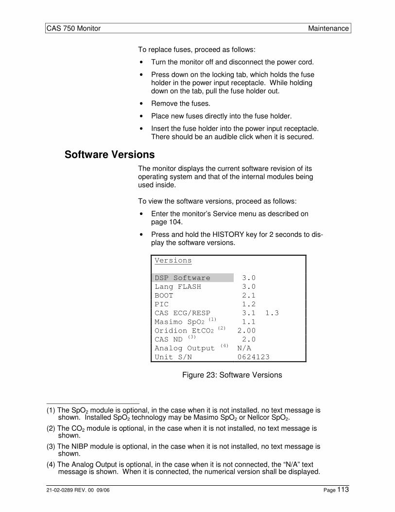
CAS 750 Monitor Maintenance
21-02-0289 REV. 00 09/06 Page 113
To replace fuses, proceed as follows:
• Turn the monitor off and disconnect the power cord.
• Press down on the locking tab, which holds the fuse holder in the power input receptacle. While holding down on the tab, pull the fuse holder out.
• Remove the fuses.
• Place new fuses directly into the fuse holder.
• Insert the fuse holder into the power input receptacle. There should be an audible click when it is secured.
Software Versions
The monitor displays the current software revision of its operating system and that of the internal modules being used inside. To view the software versions, proceed as follows:
• Enter the monitor’s Service menu as described on page 104.
• Press and hold the HISTORY key for 2 seconds to dis-play the software versions.
Versions
DSP Software 3.0
Lang FLASH 3.0
BOOT 2.1
PIC 1.2
CAS ECG/RESP 3.1 1.3
Masimo SpO2 (1) 1.1
Oridion EtCO2 (2) 2.00
CAS ND (3) 2.0
Analog Output (4) N/A
Unit S/N 0624123
Figure 23: Software Versions
(1) The SpO2 module is optional, in the case when it is not installed, no text message is
shown. Installed SpO2 technology may be Masimo SpO2 or Nellcor SpO2.
(2) The CO2 module is optional, in the case when it is not installed, no text message is shown.
(3) The NIBP module is optional, in the case when it is not installed, no text message is shown.
(4) The Analog Output is optional, in the case when it is not connected, the “N/A” text message is shown. When it is connected, the numerical version shall be displayed.

Maintenance CAS 750 Monitor
Page 114 21-02-0289 REV. 00 09/06
• Press the RETURN key to exit and return to the Main screen.
Note: If no key is pressed for 60 seconds, the monitor will automatically exit the Versions menu and return to the Main screen.
Storage
Refer to paragraph “Operating Environment” on page 142 for storage temperature information.
Warning: If it becomes necessary to store the monitor for longer than 6 months, remove the monitor’s battery pack and place the monitor in its original packing container if available.
Note: Batteries not charged and left in storage for more than six months could degrade and not recharge to full ca-pacity.

CAS 750 Monitor Printer
21-02-0289 REV. 00 09/06 Page 115
12 Printer
Note: The Citizen Model CMP-10 Mobile Printer that is used with the CAS 750 Monitor has proprietary software installed in it for communication. For more detailed information on the Citizen Model CMP-10 Mobile Printer, refer to the User’s Manual that was sup-plied with the printer.
Warning: The CAS 750 Monitor has been tested with the Citizen CMP-10 Mobile printer to comply with IEC 60601-1-1 and is the only printer that is recommended to be used with the monitor. If another printer is to be used, the user must read the Warning “Leakage Current Test “ on page 16 and follow the guidance given.
The Citizen CMP-10 Mobile Printer interfaces to the moni-tor via an Infrared Port or by using the direct connect RS232 cable (supplied with printer). The Infrared ports are located on the top of the printer and on the bottom front panel of the monitor.
Caution: For safe and proper usage of the external printer, please observe the following:
• Avoid places where fluid may enter the printer opening accidentally.
• Avoid places subject to high or low temperature ex-tremes.
• Avoid dusty places and where corrosive gasses are generated.
• Never attempt to dismantle or repair the printer mecha-nism.
• Do not drop or bump the printer. When handling the thermal paper:
• Store in a dark, cool and dry place.
• Do not place near organic solvents.
• Avoid contact with vinyl chloride films erasers or adhe-sive tapes for extended periods.
• Avoid exposure to high temperature, humidity, liquid, or sunlight.
• Always use specified thermal paper. Refer to “Other Accessories and Options“ on page 150 for order infor-mation.

Printer CAS 750 Monitor
Page 116 21-02-0289 REV. 00 09/06
Printer Controls and Indicators
Figure 24: Printer Controls and Indicators
1. Charge LED (red = charging, green = fully charged)
2. Power LED (green = power on, red/green blinking fast = end of paper, red/green blinking slow = print head overheated)
3. Infrared (IrDA) port
4. RS 232 serial interface
5. Power ON/OFF key
6. Line Feed key
7. Paper Cover Release Button (press down to open cover)
8. Paper Cutting Edge
9. Paper Cover
Printer Operation
Direct Connection
The monitor uses the DB9 connector, located on the rear panel of the monitor, to interface to the RS232 port on the Citizen CMP-10 Mobile Printer. Use the cable, which is supplied with the printer.
Note: When using the direct connect method; connect the printer’s serial cable to the printer before turning the printer on.

CAS 750 Monitor Printer
21-02-0289 REV. 00 09/06 Page 117
Infrared Connection
Note: When using the infrared port, disconnect the printer serial cable from the printer before turning the printer on.
Position the printer’s infrared port window in-line with the infrared window of the monitor.
Note: When using the Infrared port, it is important to keep the two devices close together (less than three feet / one meter) and in-line to maintain proper communications. The monitor can perform a communication test to verify the In-frared connection. Refer to paragraph “IrDA Test” on page105.
Note: When using the IrDA port for printing, it is recom-mended to keep all items clear of the communications path between the monitor and the printer.
• To turn the printer on, press and hold the ON/OFF key for 1 second. The Power LED illuminates green.
• To turn the printer off, press and hold the ON/OFF key. The Power LED will illuminate red and change back to green. When the LED illuminates green, remove your finger from the key.
Note: If the monitor is turned on and the printer is already on, the CAS logo is printed automatically.
The CMP-10 Mobile Printer has an Auto Power Off feature. If the monitor and printer become separated and during 10 minutes no data has been sent and the Line Feed (LF) key has not been pressed, the printer will automatically shutoff.
The monitor periodically sends a “wake-up” message to the printer that will disable the Auto Power Off feature.

Printer CAS 750 Monitor
Page 118 21-02-0289 REV. 00 09/06
Sample printouts of both, Trend and Alarm Histories, are shown below.
750X Series Monitor
21-Mar-06 15:48
Patient:
__________________________
Notes:
__________________________
__________________________
Trend Hist:
HR:MN HR RR %O2 PR CO2 RR
13:35 60 15 98 59 38 16
13:35 NIBP=120/80 (90) PR= 59
13:36 60 15 98 59 38 16
13:37 60 15 98 59 38 16
13:37 NIBP=112/78 (89) PR= 61
13:38 60 15 98 59 38 16
13:39* 60 15 98 59 38 16
13:39 NIBP=120/80 (90) PR= 58
13:40 60 15 98 59 38 16
750X Series Monitor
21-Mar-06 15:48
Patient:
__________________________
Notes:
__________________________
__________________________
Alarm Hist:
HR:MN Alarm
13:39 Tachycardia: 200 BPM
Figure 25: History Sample Printouts
Note: An asterisk (*) appears in the History printout to indi-cate an Alarm has occurred during that one-minute inter-val. To print waveforms:
• Press and hold the RETURN key for 2 seconds.
The waveforms that are being displayed will print based on the selections made for Print Traces in the “Parameters Menu”. Refer to paragraph “Parameters Menu” on page 40.
Note: If the EtCO2 Print selection is “ON” and the Print Traces selection is ECG and the EtCO2 connector is in-stalled or removed, all traces shall be printed – overriding the ECG selection.
When the Print On Alarm setting in the Parameters menu is set to “ON”, the type of alarm is printed on the printout and the trace is annotated with an arrow marker to mark the point of the alarm.

CAS 750 Monitor Printer
21-02-0289 REV. 00 09/06 Page 119
Figure 26: Waveform Sample Printout
1. Header
2. Trace Names
3. Size Marker
4. Alarm Event Type
5. Numeric Information
6. Alarm Event Marker
Charging the Printer Battery
The CMP-10 Mobile Printer is equipped with a recharge-able Lithium Ion (LiION) battery pack. When the printer de-tects a Low Battery condition, the message “Low Battery” is printed and an audio indicator sounds three times.
Warning: Charge the printer battery using the AC Adapter, Model TRC-09-1100-M from GROUP WEST, or equivalent, included with the printer.
• Plug the battery charger’s cord into the printer battery charger jack, located on the rear panel.
• Plug the charger into an AC wall outlet of the appropri-ate voltage.
• Verify the Charge LED is lit red. Battery charge time is approximately 3 hours. Once the battery is fully charged, the Charge LED switches to green.

Printer CAS 750 Monitor
Page 120 21-02-0289 REV. 00 09/06
Installing Paper
Note: A red line appears when the remaining supply of thermal paper becomes low.
• Switch the printer off.
• Press the Cover Open button to access the paper compartment. Remove any remaining paper before installing the new roll.
• Place the new paper roll as shown on the illustration and pull out enough paper to reach out over the control panel of the printer.
• Close the paper door.
Figure 27: Paper Installation
Note: Make sure that the paper is correctly placed. If it is tilted in one or another direction and does not come out straight from under the cover, open the door and reposition the roll again.
Warning: Do not touch the print head or paper cutter while replacing the printer paper.

CAS 750 Monitor Printer
21-02-0289 REV. 00 09/06 Page 121
Removing the Battery Pack
Warning: Do not operate the printer or connect it to the monitor with the battery pack is removed.
Warning: Never change the battery pack while the battery charger is plugged in and/or the monitor is being operated.
• Switch the printer off.
• Disconnect the printer from the monitor and unplug the wall charger cord.
• Open the battery door by pressing in on the battery cover and pushing upward.
Figure 28: Opening the Battery Door
• Remove the battery cover.
• Remove the battery pack from the compartment and disconnect its connecting cable.

Printer CAS 750 Monitor
Page 122 21-02-0289 REV. 00 09/06
Installing the new Battery Pack:
Figure 29: Installing the New Battery
• Connect the battery cable into the battery connector.
• Insert the battery and its connecting cable into the bat-tery compartment.
• Replace the battery cover by sliding it in from the back of the printer and pushing down to lock it in place.
Caution: Be sure to place the battery cover firmly in its po-sition after installing the new battery pack.
Warning: Do not disassemble the battery pack or batter-ies. The batteries contain electrolytes, which can cause in-jury to eyes, skin and clothing.
Note: Under various state and local laws, it may be illegal to dispose of this battery into the municipal waste stream. Check with your local authorities for instructions on recy-cling options in your area.

CAS 750 Monitor External Device Interfacing
21-02-0289 REV. 00 09/06 Page 123
13 External Device Interfacing
Nurse Call and RS232 Interface
Note: The monitor uses the same DB9 connector for the Nurse Call and the RS232 interface.
Pin
Signal
1 Nurse Call (N.O.) 2 Serial Receive In 3 Serial Transmit Out 4 No Connection 5 Isolated Ground 6 Nurse Call (N.C.) 7 No Connection 8 No Connection
9 Nurse Call (common)
Figure 30: DB9 Connector
RS232 Interface
The monitor uses the DB9 connector to interface to the RS232 port on the Citizen CMP-10 Mobile Printer. Use the cable, which is supplied with the printer.
The RS232 interface may be used for data collection or service purposes. Refer to the documentation provided with each application.
Note: The CAS 750 Monitor is not equipped with interfaces to remote equipment or network(s) to duplicate alarms.
Nurse Call Interface
The Nurse Call output is activated by any violation of a pa-tient high or low alarm limit. The Nurse Call is not affected by the silencing/muting of the audio when pressing the Si-lence/Reset key.
The output is compatible with most Nurse Call Systems in that there is no polarity to the connection. The monitor provides two isolated relay switches, a closing and an opening contact. For normally open applications, the nurse call system needs to be connected to pins 1 and 9 of the DB9 connector. For normally closed applications, the nurse call system needs to be connected to pins 6 and 9.

External Device Interfacing CAS 750 Monitor
Page 124 21-02-0289 REV. 00 09/06
Refer to paragraph “Nurse Call Interface” on page 143 for technical specifications.
Warning: Qualified service personnel only should install the Nurse Call Interface connection.
Warning: The interconnection to the Nurse Call system may increase the total leakage current. The user must read the Warning “Leakage Current Test “and follow the guidance given.
Note: Even though the Nurse Call Interface allows remote alarm indication, it does not replace appropriate bedside surveillance by trained clinicians.
Mounting
There are several mounting devices (e.g. roll stand or swivel mount) available for the monitor. In all cases, the 4 screw threads at the back are used to attach the monitor to the mounting device.
Figure 31: Mounting Threads
1. Screw Thread (one of four) Note: Follow the instructions provided with each specific mounting solution.

CAS 750 Monitor Appendix
21-02-0289 REV. 00 09/06 Page 125
14 Appendix
Symbols
The following is a summary of all symbols used on the monitor and accessories. Symbols may occur on the product or on its packag-ing.
Front Panel Symbols
Power Indicator POWER (On/Standby) ALARMS (Silence/Reset) NIBP (Start, Cancel, Menu) RETURN (Main Screen, Freeze, Print) PARAMETERS
LIMITS HISTORY
AUDIO/VISUAL UP DOWN

Appendix CAS 750 Monitor
Page 126 21-02-0289 REV. 00 09/06
Screen Indicators
Heart Beat Indicator Respiration Breath Indicator Battery Charge Level Indicator Silence Indicator Bar Graph Indicator
Symbols near Accessory Connections
Patient connections are Type BF Patient connections are Type CF Communication Port RS232 Connector ECG/Respiration Input Connector Pulse Oximeter Probe Input Connector CO2 Input Connector CO2 Scavenger Exhaust Port NIBP Hose and Cuff Connector Temperature Probe Input Connector

CAS 750 Monitor Appendix
21-02-0289 REV. 00 09/06 Page 127
Symbols on Monitor or Printer
CAUTION, read instructions before using. Potential Equalization Post This symbol appears here instead of on the unit. The first two digits of the unit’s serial number indicate the year of manufacture in the 21st century. Protection against ingress of water. The CE Mark and Notified Body Registration Number signify the device has met all essential requirements of European Medical Device Directive 93/42/EEC. Indicates this monitor is subject to the Waste Electrical and Elec-tronic Equipment Directive in the European Union. Alternating Current Symbol for DC power polarity Symbol for DC power Recycling suggested
Class II equipment Read instructions in Printer Manual

Appendix CAS 750 Monitor
Page 128 21-02-0289 REV. 00 09/06
Symbols on Packaging
Lot Number Relative Humidity for Storage and Transport Single Patient Use. Do Not Reuse Storage and Transport Temperatures Use By date (yyyy-mm)

CAS 750 Monitor Appendix
21-02-0289 REV. 00 09/06 Page 129
Warranty Policy
MONITORS (CAS 750) All products are sold by CAS Medical Systems, Inc. under the warranties set forth in the follow-ing paragraphs. Such warranties are extended only with respect to the purchase of this product directly from CAS Medical Systems, Inc. or CAS’s Authorized Distributors as new merchandise and are extended to the first buyer thereof, other than for resale. The CAS 750 Monitor is warranted for a period of twenty-four (24) months. All products, exclud-ing printers, if applicable, are warranted to be free from functional defects in materials and workmanship and to conform to the description of the product contained in the Operator/Service Manual, published specifications, and accompanying labels and/or inserts, provided that the same is properly operated under conditions of normal use in accordance with applicable safety and regulatory requirements, and that replacements and repairs are made in accordance with the instructions provided by CAS Medical Systems, Inc. The same warranty conditions are made for a period of twelve (12) months with respect to print-er and battery. A ninety (90) days warranty is provided for non-disposable accessories such as reusable SpO2 sensors, reusable temperature probes and other accessories provided by CAS as part of the original purchase. CAS warrants disposable or single-patient-use products, in-cluding blood pressure cuffs, for out-of-box failure only. Reusable blood pressure cuffs are war-ranted for one year. Where the accessory is not a CAS Medical Systems, Inc. manufactured product, the manufacturer’s own warranty applies. Warranty of accessories purchased sepa-rately from listed suppliers will be the responsibility of such listed suppliers. Damage to any part through misuse, neglect, or accident, or by affixing any accessories or attachments other than CAS, Statcorp, Masimo®, Nellcor®, Nonin®, Oridion®, YSI® and Welch Allyn® manufactured accessories or attachments, is not covered by this warranty. The foregoing warranties shall not apply if the product has been configured, modified, adjusted or repaired other than by CAS Medical Systems, Inc. or by persons expressly authorized by CAS Medical Systems, Inc., or not in accordance with written instructions provided by CAS Medical Systems, Inc., or if the product has been subjected to misuse, negligence, or accident. This warranty is void if the printer is used with any paper other than that specified by CAS Medi-cal Systems, Inc.

Appendix CAS 750 Monitor
Page 130 21-02-0289 REV. 00 09/06
CAS reserves the right to perform warranty service operations in its own factory, at an author-ized repair facility, or at the customers’ site. CAS Medical Systems, Inc.’s sole and exclusive obligation and Buyer’s sole and exclusive remedy under the above warranties, is limited to re-pairing or replacing, free of charge, a product which is reported in writing or via telephone to CAS Medical Systems, Inc., has a Return Material Authorization (RMA) number assigned and which is returned during normal business hours, transporting charges prepaid to: CAS Medical Systems, Inc. 44 East Industrial Road Branford, CT. 06405 USA Telephone: +1 203 488 6056 Fax: +1 203 488 9438 E-mail: [email protected] CAS MEDICAL SYSTEMS, INC. SHALL NOT BE OTHERWISE LIABLE FOR ANY DAMAGES INCLUDING, BUT NOT LIMITED TO, INCIDENTAL DAMAGES, CONSEQUENTIAL DAMAGES OR SPECIAL DAMAGES. THERE ARE NO EXPRESS OR IMPLIED WARRANTIES WHICH EXTEND BEYOND THE WARRANTIES HEREINABOVE SET FORTH. CAS MEDICAL SYSTEMS, INC. MAKES NO WARRANTY OF MERCHANTABILITY OR FITNESS FOR A PARTICULAR PURPOSE WITH RESPECT TO THE PRODUCT OR PARTS THEREOF.

CAS 750 Monitor Appendix
21-02-0289 REV. 00 09/06 Page 131
Monitor Error Messages
Clock Battery
The monitor’s internal clock battery is almost discharged.
• The monitor needs to be serviced.
Dead Battery
The battery is fully discharged.
• Recharge the battery for at least 5 hours.
Low Battery
The battery is almost discharged. At least 30 minutes of operation is available from when the message first appears.
• Recharge the battery as soon as possible.
System Error
A failure has occurred on the Main Board.
• The monitor needs to be serviced.
Power Failure
Power was disconnected from the monitor.
• Press the ALARM key to clear the message.
OR
• Turn the monitor off and on again.
SET CLOCK Time and date values are incorrect.
• Set the monitor’s clock.
• If the condition persists after setting the monitors clock, then the monitor’s internal clock battery needs to be replaced.

Appendix CAS 750 Monitor
Page 132 21-02-0289 REV. 00 09/06
Monitor Configurations
CAS 750 Models with AC Power Supply
CAS 750E-1 ECG/Respiration, Temperature
CAS 750E-2 ECG/Respiration, Temperature, MAXNIBP®
CAS 750E-2MS ECG/Respiration, Temperature,
Masimo SpO2
CAS 750E-2NL ECG/Respiration, Temperature,
Nellcor SpO2
CAS 750E-3MS ECG/Respiration, Temperature, MAXNIBP®, Masimo SpO2
CAS 750E-3NL ECG/Respiration, Temperature, MAXNIBP®, Nellcor SpO2
CAS 750E-3MSC ECG/Respiration, Temperature,
Oridion CO2, Masimo SpO2
CAS 750E-3NLC ECG/Respiration, Temperature,
Oridion CO2, Nellcor SpO2
CAS 750E-4MS ECG/Respiration, Temperature, MAXNIBP®, Oridion CO2, Masimo SpO2
CAS 750E-4NL ECG/Respiration, Temperature, MAXNIBP®, Oridion CO2, Nellcor SpO2
CAS 750C-2MS Oridion CO2, Masimo SpO2
CAS 750C-2NL Oridion CO2, Nellcor SpO2
CAS 750C-3MS Oridion CO2, Masimo SpO2, MAXNIBP®
CAS 750C-3NL Oridion CO2, Nellcor SpO2, MAXNIBP®
CAS 750S-2MS Masimo SpO2, MAXNIBP®
CAS 750S-2NL Nellcor SpO2, MAXNIBP®
Table 4: CAS 750 Models with AC Power

CAS 750 Monitor Appendix
21-02-0289 REV. 00 09/06 Page 133
CAS 750 Models with 12 VDC Power Input
CAS 750EM-1 ECG/Respiration, Temperature
CAS 750EM-2 ECG/Respiration, Temperature, MAXNIBP®
CAS 750EM-2MS ECG/Respiration, Temperature,
Masimo SpO2
CAS 750EM-2NL ECG/Respiration, Temperature,
Nellcor SpO2
CAS 750EM-3MS ECG/Respiration, Temperature, MAXNIBP®, Masimo SpO2
CAS 750EM-3NL ECG/Respiration, Temperature, MAXNIBP®, Nellcor SpO2
CAS 750EM-3MSC ECG/Respiration, Temperature,
Oridion CO2, Masimo SpO2
CAS 750EM-3NLC ECG/Respiration, Temperature,
Oridion CO2, Nellcor SpO2
CAS 750EM-4MS ECG/Respiration, Temperature, MAXNIBP®, Oridion CO2, Masimo SpO2
CAS 750EM-4NL ECG/Respiration, Temperature, MAXNIBP®, Oridion CO2, Nellcor SpO2
CAS 750CM-2MS Oridion CO2, Masimo SpO2
CAS 750CM-2NL Oridion CO2, Nellcor SpO2
CAS 750CM-3MS Oridion CO2, Masimo SpO2, MAXNIBP®
CAS 750CM-3NL Oridion CO2, Nellcor SpO2, MAXNIBP®
CAS 750SM-2MS Masimo SpO2, MAXNIBP®
CAS 750SM-2NL Nellcor SpO2, MAXNIBP®
Table 5: CAS 750 Models with DC Power

Appendix CAS 750 Monitor
Page 134 21-02-0289 REV. 00 09/06
Monitor Configuration Record
Monitor Model
CAS 750 ……………. CAS 750M……………. Serial Number: ………………………
Installed Option Parameters
� ECG, Respiration and Temperature � NIBP � SpO2 � CO2
Main Screen Defaults
Channel 1 :……………………………
Channel 2 :……………………………
Channel 3 :……………………………
Alarm Limit Defaults
Parameters Adult Neonate
High Low High Low
Heart Rate
%SpO2
SatSeconds
Pulse Rate
EtCO2
FiCO2
Resp. Rate
No Resp.
Systolic
Diastolic
Date: ________________ Unit: ___________________________

CAS 750 Monitor Appendix
21-02-0289 REV. 00 09/06 Page 135
Specifications
ECG
Input: 3 or 5 leads
Leads: I, II, III, aVL, aVR, aVF, V
Frequency Response: 0.5 to 40 Hz
Common Mode Rejection: > 90 dB
Gain: Automatic or selectable (X.5, X1, X2, X4, X8 or X16)
Pacer Detection: Yes, meets AAMI Standards
Pacer Rejection: Yes, meets AAMI Standards
Heart Rate Range: Adult: 0, 15 - 300 BPM Neonate: 0, 15 - 350 BPM
Accuracy: ± 3 BPM or ± 3%, whichever is greater
Resolution: 1 BPM
Update: 1 second
Sensitivity Adjustment: Automatic
Minimum Signal: Neonate mode: 0.20 mV peak-to-peak Pediatric/Adult mode: 0.20 mV peak-to-peak
Waveform Display: QRS waveform, fixed for trace 1 (750E)
Display Sweep Speeds: 12.5, 25, 50 mm/Sec
Patient Alarms:
High HR:Low HR:Asystole:
Adjustable Adjustable 4 seconds no QRS
Equipment Alarms:
Loose Lead: Threshold at 2.0 to 2.5 K ohms
Alarm Delay Time: 5 seconds
QRS Tone Volume: Adjustable in 5 steps and Off
Temperature
Input: YSI® 400 compatible
Range: 28 to 43 °C (82.4 to 109.4 °F)
Accuracy: ± 0.1 °C (±0.2°F)
Resolution: 0.1 °C or 0.1 °F

Appendix CAS 750 Monitor
Page 136 21-02-0289 REV. 00 09/06
Respiration
Method: Impedance Pneumography
Sensing Electrodes: LA-RA
Sense Frequency: 63 kHz
Base Impedance Range: Adult mode: 0 to 3.5 K ohms Neonate mode: 0 to 2.5 K ohms
Bandwidth: 0.05 to 2.5 Hz
Sensitivity Adjustment: Automatic
Trigger Level: Minimum trigger at 0.20 ohm.
Respiration Rate:
Range in Neonate mode: 0 (No RESP), 12-150 BrPM
Range in Adult mode: 0 (No RESP), 6-150 BrPM
Accuracy: 0-122 BrPM, ± 1 BrPM 123-150 BrPM, ± 2 BrPM
Resolution: 1 BrPM
Update: 1 second
Waveform Display: Selectable for trace 2 or 3
Display Sweep Speeds: 3, 6.25, 12.5 mm/Sec
Patient Alarms:
High RR:Low RR:
No Respiration:
Adjustable, 5 seconds delay Adjustable, 5 seconds delay Adjustable from 10 Sec. to 60 Sec.

CAS 750 Monitor Appendix
21-02-0289 REV. 00 09/06 Page 137
Oximetry
Masimo SET®
Type: Functional Oxygen Saturation
Wavelengths:
Red: 660 Nanometers
Infrared: 905 Nanometers
Radiant Power: 0.79mW maximum at 50 mA, pulsed
Measurement Range:
%SpO2: 0-100%
Pulse Rate: 25-240 BPM
Accuracy:
%SpO2: Sensor Accuracy DC-195 70 - 100%, +/-2 digits (1 S.D.) LNOP® Adt LNOP Adt Long LNOP DCI LNOP DCSC LNOP DC1P LNOP DC150 LNOP Ear LNOP Pdt
Sensor Accuracy LNOP Neo 70 - 100%, +/-3 digits (1 S.D.) LNOP Neo PT LNOP NeoPT-L LNOP Neo-L LNOP Inf-L
Pulse Rate: ± 3 BPM
Update of Numeric: every 1 second
Waveform Display: Plethysmogram, fixed for trace 1 (750C and 750S), selectable for trace 2 or 3
Sweep Speeds: 12.5, 25 or 50 mm/sec
Patient Alarms: High and low limits on %SpO2, adjustable. High and low limits on Pulse Rate, adjustable.
Alarm Delay: 0 or 10 seconds

Appendix CAS 750 Monitor
Page 138 21-02-0289 REV. 00 09/06
Nellcor® OxiMax®
Type: Functional Oxygen Saturation
Wavelengths:
Red: 660 Nanometers
Infrared: 890 Nanometers
Power: Not exceeding 15 mW
Measurement Range:
%SpO2: 1-100%
Pulse Rate: 20-240 BPM
Accuracy:
%SpO2: Sensor Accuracy MAX-A 70 - 100%, +/-2 digits (1 S.D.) MAX-AL MAX-N MAX-P MAX-I MAX-FAST
Sensor Accuracy OxiCliq A 70 - 100%, +/-2.5 digits (1 S.D.) OxiCliq I OxiCliq N OxiCliq P
Sensor Accuracy DS-100A 70 - 100%, +/-3 digits (1 S.D.) D-YS OXI-A/N OXI-P/I
Sensor Accuracy D-YS 70 - 100%, +/-3.5 digits (1 S.D.) D-YSE D-YSPD
Sensor Accuracy MAX-R 80 - 100%, +/-3.5 digits (1 S.D.)
Pulse: ± 3 digits
Updated of Numerics: every 1 second
Waveform Display: Plethysmogram, fixed for trace 1 (750C and 750S), selectable for trace 2 or 3
Sweep Speeds: 12.5, 25 or 50 mm/sec
Patient Alarms: High and low limits on %SpO2, adjustable. High and low limits on Pulse Rate, adjustable.
Alarm Delay: %SpO2: SatSeconds™ Pulse: 0 or 10 seconds

CAS 750 Monitor Appendix
21-02-0289 REV. 00 09/06 Page 139
NIBP Measurement
Technique: Oscillometric (MAXNIBP Technology).
Patient Range: Adult – Neonate
Self Test: System self test is performed each time power is turned on.
Auto Zero: Zero pressure reference is automatically es-tablished after every reading.
Inflation: Initial inflation to 150 mmHg (Adult) or 85 mmHg (Neonatal) or user selectable. (Adap-tive, 80, 100, 120, 140, 150, 160, 180, 200) - Adult; (Adaptive, 60, 80, 85, 100, 120) - Neo-natal. Subsequent inflation to approximately 30 mmHg greater than previous Systolic pres-sure.
Deflation: Automatically after measurement. If cuff pressure exceeds 290 mmHg (Adult) If cuff pressure exceeds 145 mmHg (Neo-nate) If measurement time exceeds 120 seconds (Adult), 90 seconds (Neonate) If safety timer detects microprocessor failure
Max Measurement Time: Limited to 120 seconds (Adult), 90 seconds (Neonate)
Overpressure: If cuff pressure exceeds 290 mmHg (Adult), 145 mmHg (Neonate)
Measurement Range: Adult Neonate
Systolic: 30-255 mmHg 30-135 mmHg
Diastolic: 15-220 mmHg 15-110 mmHg
MAP: 20-235 mmHg 20-125 mmHg
Pulse Rate Range: 30-240 BPM 40-240 BPM
Accuracy:
Blood Pressure: ± 5 mmHg, Standard deviation no greater than 8 mmHg.
Pulse Rate: ± 2% or ± 2 BPM, whichever is greater.
Patient Alarms: High and low limits for Systolic Pressure, ad-justable. High and low limits for Diastolic Pressure, adjustable.
Accuracy complies with that given in American National Standard for Electronic or Automated Sphygmomanometers, ANSI/AAMI SP10, 2002. Adult blood pressure measurements determined with this device are equivalent to those obtained by an auscultatory blood pressure meas-urement device and neonatal ones are equivalent to those obtained by an intra-arterial blood pressure device, within the limits prescribed by the American National Standard for Electronic or Automated Sphygmoma-nometers. The 4th Korotkoff sound was used to determine Diastolic pressure. Study findings are available.

Appendix CAS 750 Monitor
Page 140 21-02-0289 REV. 00 09/06
Capnography
Method: Sidestream Capnography (MicroStream®)
Patient Range: Adult - Neonate
Units: mmHg, % or kPa
Sample Rate: 50 ml/min ± 7.5 ml/min
System Response Time: 2.9 seconds typical, (includes delay and rise time)
Rise Time: Adult and Neonate: 190 msec max.
Delay Time: 2.7 seconds (typical)
Frequency Response: EtCO2 accuracy is maintained up to 80 breaths/min. (For maintaining accuracy for respiration rate over 60 bpm, use Neonate mode.) From 81 to 150 bpm accuracy is ±12%, if the EtCO2 is higher than 18.8 mmHg in Neonate mode.
Ambient Pressure: Compensated internally – automatic
Range: 0-99 mmHg (0-13.2 kPa and 0-13.0 vol% at sea level)
Initialization Time: 30 seconds (typical)
Accuracy:
Before steady state: 0 – 38 mmHg ± 4 mmHg 39 – 99 mmHg ± 12% of reading
Steady state: 0 – 38 mmHg ± 2 mmHg 39 – 99 mmHg ± 5% of reading +0.08% for every 1 mmHg above 38 mmHg.
Resolution: 1 mmHg, 0.1 % or 0.1 kPa
Respiration Rate: 0 - 150 breaths/min
Waveform Display: CO2 waveform, selectable for trace 2 or 3
Sweep Speeds: 3, 6.25, 12.5 mm/sec
Patient Alarms: High and low limits on EtCO2, adjustable High FiCO2, adjustable

CAS 750 Monitor Appendix
21-02-0289 REV. 00 09/06 Page 141
Patient Alarms
Adjustable Alarms: High and low alarms for Heart Rate, %SpO2, Pulse Rate, EtCO2, High FiCO2, Respiration Rate, Systolic Pressure, Diastolic Pressure, No Respiration.
Fixed Alarms: Asystole
Alarm Indicators: Audible Red Patient Alarm LED’s Yellow Equipment Alarm LED’s Text in Patient Message Window
Patient Parameter Neonatal Limit Range Adult Limit Range
Low High Low High Heart Rate: 25 to 235 BPM 25 to 235 BPM 25 to 235 BPM 25 to 235 BPM
%SpO2: 70 to 95 % 80 to 99 % 70 to 95 % 80 to 99 % SatSeconds: 10 to 100 N/A 10 to 100 N/A
EtCO2: 1 to 99 mmHg .1 to 13.2 %
.1 to 13.2 kPa
1 to 99 mmHg .1 to 13.2 %
.1 to 13.2 kPa
1 to 99 mmHg .1 to 13.2 %
.1 to 13.2 kPa
1 to 99 mmHg .1 to 13.2 %
.1 to 13.2 kPa FiCO2: N/A 3 to 30 mmHg,OFF
.4 to 4.0 %,OFF .4 to 4.0 kPa,OFF
N/A 3 to 30 mmHg,OFF .4 to 4.0 %,OFF
.4 to 4.0 kPa,OFF Respiration Rate: 5 to 145 BrPM 5 to 145 BrPM 5 to 145 BrPM 5 to 145 BrPM
No Respiration: 5 to 30 Sec N/A 5 to 30 Sec N/A SYS: 35 to 130 mmHg 35 to 130 mmHg 35 to 250 mmHg 35 to 250 mmHg DIA: 20 to 105 mmHg 20 to 105 mmHg 20 to 215 mmHg 20 to 215 mmHg
Each alarm limit may also be selected “OFF” individually or as a whole. Low Limits cannot be set above the associated High Limit. High Limits cannot be set lower than the associated Low Limit.
Operating Modes
Patient Modes: Neonate or Adult
ECG: Continuous Monitoring
Respiration: Impedance Pneumography
NIBP: Manual, STAT or Automatic (at preset inter-vals).
%SpO2: Continuous Monitoring
CO2: Continuous Monitoring
Temperature: Continuous Monitoring
History: Trend: Review of previous measurements
Alarm: Review of previous alarms
Other Modes: Stand-by mode and Auto Dim (based on model)

Appendix CAS 750 Monitor
Page 142 21-02-0289 REV. 00 09/06
Display
Display: LCD display of measurement results, instruc-tions, troubleshooting messages, waveforms and signal strength bar.
Numerics: HR, PR, %SpO2, NIBP (Systolic, Diastolic and MAP or PR), EtCO2 (mmHg, % or kPa), RR, Temp (in °C or °F).
Waveforms: Up to 3 traces, ECG, SpO2, Impedance Res-piration, CO2.
Sweep Speeds: 12.5, 25 or 50 mm/s for ECG and SpO2. 3.0, 6.25 or 12.5 mm/s for Resp. and CO2.
Trend History: 480 1-minute entries of all parameters.
Alarm History: 25 most recent alarms
Physical Dimensions and Weight
(Fully configured unit with battery)
H x W x D: 170 mm x 215 mm x 102 mm (6.75 in x 8.5 in x 4.0 in)
Weight: 2.0 kg (4.4 lbs)
Operating Environment
Operating Temperature: 0 to 50°C (32°F to 122°F)
Humidity: 15 to 95% RH, non-condensing
Altitude: 10,000 to –1,250 ft (700 to 1050 hPa)
Monitors may not meet performance specifications if stored or used out-side temperature and humidity ranges. When moving the monitor from a storage location, wait at least one-hour prior to use to allow the monitor to adjust to room temperature.
Storage/Transport Environment
Storage/Transport Temperature:
-20 to 60°C (-4°F to 149°F)
Humidity: 15 to 95% RH, non-condensing
Altitude: 10,000 to –1,250 ft (700 to 1050 hPa)

CAS 750 Monitor Appendix
21-02-0289 REV. 00 09/06 Page 143
Power
External Power:
AC: 100-240 VAC, 50/60 Hz, 0.5 A Fuse Rating – T500mAL250V or T1.25AL250V (two provided) Refer to monitor labeling for actual fuse rating
DC (optional): +12 VDC; 7W Fuse Rating – Littelfuse Type 154, Slo-Blo, 5.0A, 125VAC or approved equivalent (one provided)
Chassis Leakage Current: 100 µA (maximum)
Battery: NiMH battery pack (user removable).
Charge Time: 3-5 hours
Operating Time: 3 hrs (minimum)
Serial Interface
Interface Type: Bi-directional Serial Communication
Speed: 9600 for Printer 115200 for CAS Serial Protocol
Signal Level: RS232C
Data Length: 8 bits
Start Bit: 1 bit
Stop Bit: 1 bit
Parity: None
Flow Control: None
Nurse Call Interface
Relay contacts: Floating, one opening and one closing con-tact.
Max. Switching Power: 0.3 A at 120 VAC or 1.0 A at 30 VDC
Max. Delay: < 0.5 seconds.
Standards
Units comply with the following requirements:
ANSI/AAMI SP-10: 2002
CE marking according to Directive 93/42/EEC
IEC 60601-1, EN 60601-1-2
IEC 60601-2-27, IEC 60601-2-30, IEC 60601-20-49
EN 864, EN 865
UL classified – UL 60601-1, CAN/CSA C22.2 No. 60601.1
All units covered by U.S. patent 4,796,184 and 5,022,403. Other patents pending.

Appendix CAS 750 Monitor
Page 144 21-02-0289 REV. 00 09/06
Certificates
Electronic Emissions and Immunity
The Model 750 Monitor is intended for use in the electromagnetic environment specified below. The customer or the user of the Model 750 Monitor should assure it is used in such an environment. Emissions Test Compliance Electromagnetic Environment
RF emissions – CISPR 11
Group 1 The Model 750 Monitor uses RF energy only for its in-ternal function. Therefore, its RF emissions are very low and are not likely to cause any interference in nearby electronic equipment.
RF emissions – CISPR 11
Class B
Harmonic emissions IEC 61000-3-2
Class B
Voltage fluctuations / flicker emissions
Complies
The Model 750 Monitor is suitable for use in all estab-lishments, including domestic establishments and those directly connected to the public low-voltage power sup-ply network that supplies buildings used for domestic purposes.
Immunity Test IEC 60601 Test
Level Compliance Level Electromagnetic Environment
Guidance
Electrostatic discharge (ESD) IEC 61000-4-2
±6 kV contact
±8 kV air
±6 kV contact
±8 kV air
Floors should be wood concrete or ceramic tile. If floors are cov-ered with synthetic material, the relative humidity should be at least 30%.
Electrical fast transient/burst IEC 61000-4-4
±2 kV for power
supply lines
±1 kV for in-put/output lines
±2 kV for power
supply lines
±1 kV for in-put/output lines
Mains power quality should be that of a typical commercial or hospital environment.
Surge IEC 61000-4-5
±1 kV differential mode
±2 kV common
mode
±1 kV differential mode
±2 kV common
mode
Mains power quality should be that of a typical commercial or hospital environment.
Voltage Dips, short interruptions and volt-age variations on power supply input lines IEC 61000-4-11
< 5% UT (>95% dip in UT) for 0.5 cycle. 40% UT (60% dip in UT) for 5 cycles. 70% UT (30% dip in UT) for 25 cy-cles. < 5% UT (> 95% dip in UT) for 5 seconds.
< 5% UT (>95% dip in UT) for 0.5 cycle. 40% UT (60% dip in UT) for 5 cycles. 70% UT (30% dip in UT) for 25 cy-cles. < 5% UT (> 95% dip in UT) for 5 seconds.
Mains power quality should be that of a typical commercial or hospital environment. If user of the model 750 requires continued operation during power mains interruptions, it is recommended that the model 750 be powered from an uninterruptible power supply or a battery.
Power frequency (50/60 Hz) magnetic field IEC 61000-4-8
3 A/m 3 A/m Power frequency magnetic fields should be at levels characteristic of a typical location in a typical commercial or hospital environ-ment.
NOTE: UT is the A.C. mains voltage prior to application of the test level.

CAS 750 Monitor Appendix
21-02-0289 REV. 00 09/06 Page 145
Guidance and Manufacturer’s Declaration – Electromagnetic Immunity The Model 750 Monitor is intended for use in the electromagnetic environment specified below. The customer or the user of the Model 750 Monitor should insure that it is used in such an environment.
Immunity Test IEC 60601 Test Level Compliance Level
Electromagnetic Environment - Guidance
Conducted RF IEC 61000-4-6 Radiated RF IEC 61000-4-3
3 Vrms 150 kHz to 80 MHz 3 V/m 80 MHz to 2.5 GHz
3 Vrms 3 V/m
Portable and mobile RF communications equipment should be used no closer to any part of the Model 750 Monitor, including cables, than the recommended separation distance calculated from the equation applicable to the frequency of the transmitter. Recommended separation distance:
d = 1.2√P
d = 1.2√P 80 MHz to 800 MHz
d = 2.3√P 800 MHz to 2.5 GHz Where P is the maximum output power rating of the transmitter in watts according to the transmitter manu-facturer and d is the recommended separation dis-tance in meters. Field strengths from fixed RF transmitters, as deter-mined by an electromagnetic site survey a , should be less than the compliance level in each frequency range. b Interference may occur in the vicinity of equipment marked with the following symbol:
NOTE 1 At 80 MHz and 800 MHz, the higher frequency range applies. NOTE 2 These guidelines may not apply in all situations. Electromagnetic propagation is effected by absorption and reflection from structures, objects and people. a Field strengths from fixed transmitters, such as base stations for radio (cellular / cordless) telephones and land mobile radios,
amateur radio, AM and FM radio broadcast and TV broadcast cannot be predicted theoretically with accuracy. To assess the electromagnetic environment due to fixed RF transmitters, an electromagnetic site survey should be considered. If the measured field strength in the location in which the Model 750 Monitor is used exceeds the applicable RF compliance level above, the Model 750 Monitor should be observed to verify normal operation. If abnormal performance is observed, additional measures may be necessary, such as re-orienting or relocating the Model 750 Monitor. b Over the frequency range 150 kHz to 80 MHz, field strengths should be less than 3 V/m.
Recommended Separation Distances Between Portable and Mobile RF Communications Equipment and the Model 750 Monitor
The Model 750 Monitor is intended for use in an electromagnetic environment in which radiated RF disturbances are controlled. The customer or the user of the Model 750 Monitor can help prevent electromagnetic interference by maintaining a minimum dis-tance between portable and mobile RF communications equipment (transmitters) and the Model 750 Monitor as recommended below, according to the maximum output power of the communications equipment.
Separation distance according to frequency of transmitter (Meters)
Rated maximum output power of transmitter
(Watts)
150 kHz to 80 MHz
d = 1.2√P
80 MHz to 800 MHz
d = 1.2√P
800 MHz to 2.5 GHz
d = 2.3√P
0.01 0.12 0.12 0.23 0.1 0.38 0.38 0.73 1 1.2 1.2 2.3
10 3.8 3.8 7.3 100 12 12 23
For transmitters operating at a maximum output power not listed above, the recommended separation distance d in meters can be estimated using the equation applicable to the frequency of the transmitter, where P is the maximum output power rating of the transmitter in watts according to the transmitter manufacturer. NOTE 1 At 80 MHz and 800 MHz, the separation distance for the higher frequency range applies. NOTE 2 These guidelines may not apply in all situations. Electromagnetic propagation is affected by absorption and reflection from structures, objects and people.
Appendix CAS 750 Monitor
Page 146 21-02-0289 REV. 00 09/06
CE Marking Information
Compliance
The CAS750 patient monitors bear the CE mark CE-0086 indicat-ing conformity with the provisions of the Council Directive 93/42/EEC concerning medical devices and fulfills the essential requirements of Annex I of this directive.
Exceptions
None.

CAS 750 Monitor Appendix
21-02-0289 REV. 00 09/06 Page 147
Accessories
Contact our Customer Service Department or see our website for the latest product in-formation. Refer to Page 2, Contact Addresses for e-mail and phone number informa-tion.
ECG Accessories
Catalog No. Type Description 01-02-0304 3-lead ECG Trunk Cable, 3m, IEC/AAMI 01-02-0305 5-lead ECG Trunk Cable 3m, IEC/AAMI 01-02-0308 3-lead set with clips, 61cm/24", AAMI 01-02-0309 5-lead set with clips, 91cm/36", AAMI 01-02-0310 3-lead set with clips, 61cm/24", IEC 01-02-0311 5-lead set with clips, 91cm/36", IEC 01-02-0380 5-lead set with clips, 91 cm/36 inch, IEC 01-02-0381 5-lead set with clips, 91 cm/36 inch, AAMI 01-05-0016 Pregelled Snap Electrodes, Adult (12 pgks of 3) 01-05-0014 Pregelled Snap Electrodes, Infant (18 pkgs of 3) 28-02-0445 Leadwire Detangler
Tuff-Cuff Blood Pressure Cuffs
Reusable Blood Pressure Cuffs
Catalog No. Type Description 01-01-0308 CR 5216 Large Adult, 16 cm x 42 cm 01-01-0307 CR5214 Adult, 14 cm x 37.5 cm 01-01-0306 CR5212 Small, Adult12 cm x 30 cm 01-01-0249 CR5209 Child, 9 cm x 27 cm 01-01-0248 CR5207 Small Child, 7 cm x 21 cm 01-01-0258 CR5206 Infant, 6 cm x 18 cm
Safe-Cuff Blood Pressure Cuffs
Single-Patient-Use Blood Pressure Cuffs
Catalog No. Type Description 01-01-0245 CD2060 X-Large Adult, 20 cm x 50 cm 01-01-0243 CD1642 Large Adult, 16 cm x 40 cm 01-01-0241 CD1437 Adult, 14 cm x 35 cm 01-01-0239 CD1230 Small Adult, 12 cm x 30 cm 01-01-0237 CD927 Child, 9 cm x 22.5 cm 01-01-0235 CD618 Infant, 6 cm x 15 cm
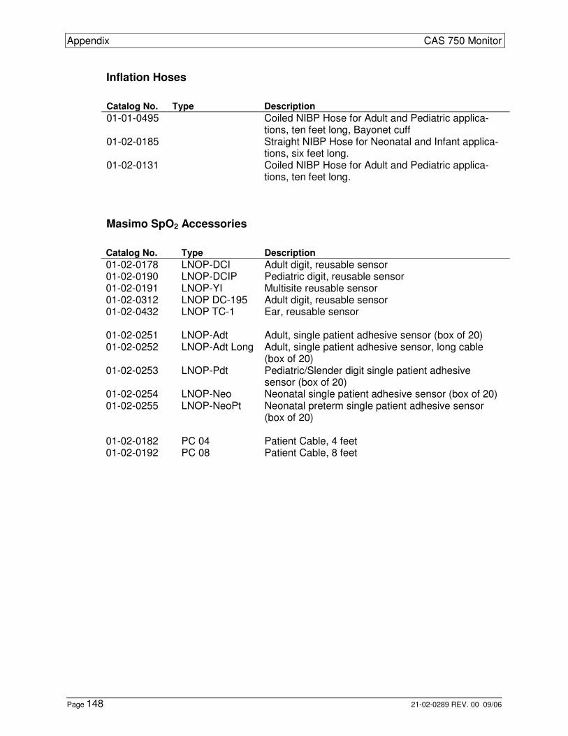
Appendix CAS 750 Monitor
Page 148 21-02-0289 REV. 00 09/06
Inflation Hoses
Catalog No. Type Description 01-01-0495 Coiled NIBP Hose for Adult and Pediatric applica-
tions, ten feet long, Bayonet cuff 01-02-0185 Straight NIBP Hose for Neonatal and Infant applica-
tions, six feet long. 01-02-0131 Coiled NIBP Hose for Adult and Pediatric applica-
tions, ten feet long.
Masimo SpO2 Accessories
Catalog No. Type Description 01-02-0178 LNOP-DCI Adult digit, reusable sensor 01-02-0190 LNOP-DCIP Pediatric digit, reusable sensor 01-02-0191 LNOP-YI Multisite reusable sensor 01-02-0312 LNOP DC-195 Adult digit, reusable sensor 01-02-0432 LNOP TC-1 Ear, reusable sensor 01-02-0251 LNOP-Adt Adult, single patient adhesive sensor (box of 20) 01-02-0252 LNOP-Adt Long Adult, single patient adhesive sensor, long cable
(box of 20) 01-02-0253 LNOP-Pdt Pediatric/Slender digit single patient adhesive
sensor (box of 20) 01-02-0254 LNOP-Neo Neonatal single patient adhesive sensor (box of 20) 01-02-0255 LNOP-NeoPt Neonatal preterm single patient adhesive sensor
(box of 20) 01-02-0182 PC 04 Patient Cable, 4 feet 01-02-0192 PC 08 Patient Cable, 8 feet
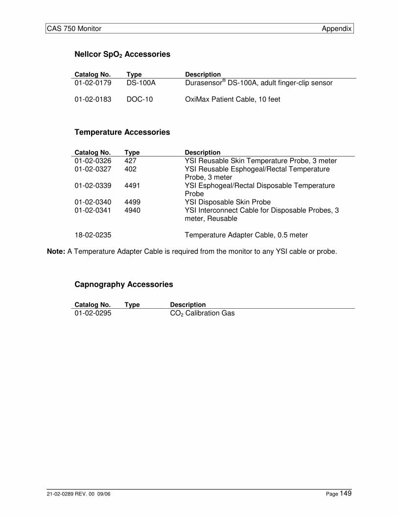
CAS 750 Monitor Appendix
21-02-0289 REV. 00 09/06 Page 149
Nellcor SpO2 Accessories
Catalog No. Type Description 01-02-0179 DS-100A Durasensor® DS-100A, adult finger-clip sensor 01-02-0183 DOC-10 OxiMax Patient Cable, 10 feet
Temperature Accessories
Catalog No. Type Description 01-02-0326 427 YSI Reusable Skin Temperature Probe, 3 meter 01-02-0327 402 YSI Reusable Esphogeal/Rectal Temperature
Probe, 3 meter 01-02-0339 4491 YSI Esphogeal/Rectal Disposable Temperature
Probe 01-02-0340 4499 YSI Disposable Skin Probe 01-02-0341 4940 YSI Interconnect Cable for Disposable Probes, 3
meter, Reusable 18-02-0235 Temperature Adapter Cable, 0.5 meter
Note: A Temperature Adapter Cable is required from the monitor to any YSI cable or probe.
Capnography Accessories
Catalog No. Type Description 01-02-0295 CO2 Calibration Gas
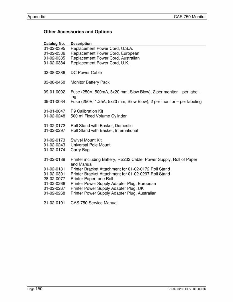
Appendix CAS 750 Monitor
Page 150 21-02-0289 REV. 00 09/06
Other Accessories and Options
Catalog No. Description
01-02-0395 Replacement Power Cord, U.S.A. 01-02-0386 Replacement Power Cord, European 01-02-0385 Replacement Power Cord, Australian 01-02-0384 Replacement Power Cord, U.K. 03-08-0386 DC Power Cable 03-08-0450 Monitor Battery Pack 09-01-0002 Fuse (250V, 500mA, 5x20 mm, Slow Blow), 2 per monitor – per label-
ing 09-01-0034 Fuse (250V, 1.25A, 5x20 mm, Slow Blow), 2 per monitor – per labeling 01-01-0047 P9 Calibration Kit 01-02-0248 500 ml Fixed Volume Cylinder 01-02-0172 Roll Stand with Basket, Domestic 01-02-0297 Roll Stand with Basket, International 01-02-0173 Swivel Mount Kit 01-02-0243 Universal Pole Mount 01-02-0174 Carry Bag 01-02-0189 Printer including Battery, RS232 Cable, Power Supply, Roll of Paper
and Manual 01-02-0181 Printer Bracket Attachment for 01-02-0172 Roll Stand 01-02-0301 Printer Bracket Attachment for 01-02-0297 Roll Stand 28-02-0077 Printer Paper, one Roll 01-02-0266 Printer Power Supply Adapter Plug, European 01-02-0267 Printer Power Supply Adapter Plug, UK 01-02-0268 Printer Power Supply Adapter Plug, Australian 21-02-0191 CAS 750 Service Manual