product manual - rfs product manual automatic pressurization dehydrator apd ... numbers and contact...
TRANSCRIPT

602400011500 Revision P2
Radio Frequency Systems 200 Pond View Drive Meriden, CT 06450 Ph. (203) 630-3311 Fax (203) 634-2272 www.rfsworld.com
ProductManualAUTOMATICPRESSURIZATIONDEHYDRATOR
APD‐DSeries

602400011500 Revision P2
Page 2 of 24
This Page Intentionally Left Blank

602400011500 Revision P2
Page 3 of 24
TABLEOFCONTENTS1 WARNINGS, CAUTIONS & NOTES ........................................................................................................... 4
2 INSTALLATION ........................................................................................................................................... 5
3 TERMS & DEFINITIONS ............................................................................................................................. 7
4 OPERATION .................................................................................................................................................. 8
5 CONTROLS AND INDICATORS............................................................................................................... 12
6 MAINTENANCE ......................................................................................................................................... 15
7 REPLACEMENT PARTS AND ACCESSORIES ....................................................................................... 17
8 OPTION / CONFIGURATION / SOFTWARE UPGRADE ....................................................................... 17
9 SPECIFICATIONS ....................................................................................................................................... 19
10 MODEL CONFIGURATION ...................................................................................................................... 20
11 RUN TIME CALCULATIONS .................................................................................................................... 21
12 TRANSMISSION LINE VOLUMES........................................................................................................... 22
13 CE DECLARATION OF CONFORMITY .................................................................................................. 24

602400011500 Revision P2
Page 4 of 24
1 WARNINGS,CAUTIONS&NOTES
NOTE:Readthismanualbeforeinstallationoroperationofthedehydrator.
NOTE:Removingtheunit’scoverwillvoidthewarranty._________________________________________________________________________________________________________ WARNING
The APD‐D series dehydrators are not compatible with single‐phasesystemsutilizing twoLineconductorsandoneneutralconductor(suchas North American 240VAC service). Earth ground must always beconnected.The APD-D series dehydrators are designed for 120/230VAC use at 50/60Hz. The AC Mains configuration must be 1/N/PE, meaning 3 conductors: 1.) Single phase Line power. (wire color: black or brown) 2.) Neutral (phase return) tied to Earth ground at the local power panel. (wire color: blue or white) 3.) Protective Earth (PE) ground. (wire color: green with yellow stripe or green) _________________________________________________________________________________________________________
Hazardousvoltagesexistinsidetheunit.Unplugthepowerbeforeservicing.
Theunitstartsautomaticallywhenpowerisapplied.Donotoperateunitwithoutcover
securedproperlyinplace.

602400011500 Revision P2
Page 5 of 24
2 INSTALLATION
2.1 SystemPurging:Proper purging of the site’s distribution system prior to dehydrator installation is important. Failure to do so may result in moisture being present in the system when the dehydrator is installed. This moisture will remain in the system until the dehydrator’s normal operation purges it from the system. If the purging is left to normal operation of the dehydrator, then the process may take days, weeks, or longer depending on the dehydrator’s installed options, system size, moisture levels, and other variables. If configured, humidity alarms may result until the humidity is purged from the system. Manually purging the pressure from the system every 24 hours and letting the dehydrator refill the system with dry air can accelerate the moisture removal process. 2.2 FlowRestrictions:Care must be taken to ensure that no flow restrictions exist in the site’s pressurized dry air distribution system. Small restrictions can cause pump times to be shorter than calculated, unit duty cycle to increase, and system upper operating pressures to be reduced. Large restrictions can cause continuous cycling of the dehydrator, which can cause issues in the waveguide or cable system and will significantly reduce the performance and service life of the unit. 2.3 InstallationLocation:The dehydrator is designed for free-standing operation on its vibration isolating rubber feet. The dehydrator should be placed on a firm, level surface. An accessory wall / rack mount shelf is available for alternative mounting methods and locations. The APD series dehydrator requires a minimum of 2" clearance on the sides and top for proper heat dissipation.
2.4 InstallationProcedure:2.4.1 Ensure that the site’s distribution system has been properly installed, purged with Nitrogen and sealed. 2.4.2 Unpack the dehydrator in the environmentally controlled location where it will be installed. Place the unit on a flat, stable surface. 2.4.3 Make sure that nothing is connected to the dehydrator’s output fitting. 2.4.4 Energize the dehydrator and let it run with nothing connected to the dry air output fitting for 3-5 minutes. 2.4.5 At this point the only indicators illuminated should be POWER, COMPRESSOR and LOW PRESSURE. 2.4.6 De-energize the dehydrator and install it in its final location. 2.4.7 Connect the dehydrator’s output to the site distribution system using a properly sized section of supplied 3/8” tubing. 2.4.8 Open all necessary distribution system valves and energize the dehydrator. 2.4.9 The dehydrator will pressurize the distribution system. Monitor the time it takes to pressurize the system. If the unit run time alarm option is configured, then verify that the run time alarm setting is above the unit’s measured run time. 2.4.10 Installation is now complete. Once normal operation is confirmed, then an alarm monitoring system can be connected.
602400011500 Revision P2
Page 6 of 24
2.5 InstallationTroubleshooting:Symptom: POWER indicator flashing once per second and compressor will not start. Possible Solution: Check for correct input voltage. The unit senses input voltage, and will not start if it is outside the specifications. Symptom: Distribution system pressure is lower than the configured upper operational pressure immediately after active operation stops. Possible Solution: Check for flow restrictions in the distribution system. All tube sizes should be 3/8”. Minimize tube lengths. Make sure all valves are fully open. Symptom: Distribution system pressure drops continuously after active operation stops. Or duty cycle is more than 5%. Or active operation occurs more often than once every 48 hours. Possible Solution: Check for leaks in the distribution system. Symptom: Distribution system pressure does not increase during active operation. Possible Solution: Check that the unit’s output fitting is connected to the distribution system with a 3/8” tube. Check for leaks in the distribution system. Symptom: Run time alarm is issued before distribution system reaches the configured upper operating pressure. Possible Solution: Check for leaks in the distribution system. Any leaks will increase the active operation run time. Possible Solution: Run time to pressurize the distribution system may have been miscalculated. Please recalculate the run time, record the unit’s model and serial numbers and contact RFS Support to reconfigure the run time alarm.
Symptom: Run time exceeds 4 hours before distribution system reaches the configured upper operating pressure. Possible Solution: Check for leaks in the distribution system. Any leaks will increase the active operation run time. Possible Solution: Altitude of installation may be too high. Verify model used is specified for operation at the altitude of installation. Possible Solution: Distribution system volume may be too large for the dehydrator model installed. Please recalculate the run time, record the unit’s model and serial numbers and contact RFS Support. Symptom: Alarm monitoring system shows an alarm but dehydrator alarm indicator not illuminated. Or alarm monitoring system shows no alarm but dehydrator alarm indicator is illuminated. Possible Solution: Check for correct alarm monitor wiring. Both normally open (NO) and normally closed (NC) connections are supplied for each alarm. Connecting the incorrect one will reverse the alarm logic. Symptom: Log file is not written to USB device when it is inserted and the power is cycled. Possible Solution: Verify that the USB device is USB 2.0 compliant. Verify that the USB device is formatted for the FAT32 file system, and that it has only one active partition.
602400011500 Revision P2
Page 7 of 24
3 TERMS&DEFINITIONS3.1 RelativeHumidity (RH) is the moisture content of the air relative to the maximum possible moisture content at the current air temperature. RH is measured in percent (%). 100% RH represents saturation, and is the point at which condensation occurs. Since RH is relative to temperature, the RH of the air in the waveguide or cable will fluxuate with the changes in air temperature. As the air temperature increases, RH will fall; as the air temperature decreases, the RH will rise. The air’s actual moisture content remains constant. 3.2 Dew Point Temperature (Td) is the temperature at or below the current temperature at which the air would be saturated with moisture (100% RH). Td is measured in the same unit as ambient temperature, typically Fahrenheit or Celsius. Dew point temperature is not affected by air temperature fluxuations. Instead, it is directly linked to the actual moisture content in the air. For that reason, dew point temperature is the measurement most applicable to dehumidification processes. Dew point temperature is fairly constant over time. Weather systems and seasonal changes are the primary cause of dew point temperature fluxuation over time. When dew point temperature and ambient air temperature are equal, then the air is saturated (100% RH), and condensation can form. Therefore, it is important to keep the dew point temperature of the air inside the waveguide or cable below the ambient temperature outside the waveguide or cable to avoid condensation.
3.3 Dew Point Reduction (Tdr) is the reduction of the dew point temperature that results from the dehumidification process. The larger the Tdr, the more efficient the dehumidification process is. 3.4 DistributionSystem is the system of air tubes, distribution manifolds, valves, and RF lines to be pressurized with dry air from the dehydrator’s output fitting. 3.5 Active dehydrator operation is when the unit’s compressor is on and pressurized dry air is being supplied from the unit’s output fitting. 3.6 RunTime is the time that the unit spends in active operation to pressurize the distribution system. 3.7 Standby dehydrator operation is when the unit is energized but the compressor is not on. The distribution system pressure is in the unit’s configured operational range, and is being monitored by the unit’s control board. This is the predominant operational condition. 3.8 DutyCycle is the time in active operation vs. standby operation, measured in percent. % = 100 3.9 Lower Operational Pressure (LOP) is the configured pressure at which the dehydrator will switch from standby to active operation to re-pressurize the system. 3.10 Upper Operational Pressure (UOP) is the configured pressure in psig at which the dehydrator will switch from active to standby operation. This is also the system pressure, or the maximum pressure desired in the distribution system.

Page
4
4.1
e 8 of 24
OPERATI
GeneralDIt is imtemperatusystem isambient The local should beensure thacould neperformanThe APressurizafor reliabwaveguidsystems. distributiocondensatThe dehyadsorptioefficiency to remove
ION
Descriptionmportant thure (Td) ins maintaineoutdoor teaverage yeae taken intat no condeegatively ance of the syAPD-D ation Dehyble dry ae, coaxial Dry preson systetion is avoiddrators utiln (PSA) palumino-sie moisture f
n:hat the dnside the ded below temperature arly low temto account.ensation occaffect the ystem. Series drators areir pressurcable and surized aiem ensurded. lize a pressrocess usinlicate molecfrom the inp
Figure6
dew point istribution the lowest expected. mperatures This will curs, which electrical Automatic e designed ization of rigid line ir in the res that
sure swingng a high cular sieveput air.
6.1‐APD‐DOperation
The dehautomaticmedia repunits are service wand mainThe Aperformaenvironmmoisture output aienvironmperformamaintenain the adripping avoided.The APdesigned controlledclimatogrenvironmarea.
nalClimatog
ydration sc, with noplacement capable ofwhen properntained. APD-D ance is depemental conpresent inir will be. ments willance, a longeance. Heavyir, corrosivwater, and PD-D seriefor operatid spacesram is showment must
gram
60
system is o need foor reactivatf years of trrly installedseries dendent on thnditions. the air, thCooler, dril result er service liy dust or pve gasses condensati
es dehydron in enclos. The own below. Thfall within
02400011500Revision P2completelyor periodiction. Theserouble-freed, operated
dehydratorhe ambientThe lesse drier theier, cleanerin betterife and lessparticulatesin the air,on must berators aresed climateoperationalhe ambientn the gray
0 2

602400011500 Revision P2
Page 9 of 24
The APD-D series dehydrators are fully automatic when energized. The system pressure is monitored in real-time during standby operation. When the system pressure is at or below the lower operational pressure, then the unit will activate and re-pressurize the system with dry air. The unit will return to standby
operation when the upper operational pressure is reached. A dehydrator duty cycle of less than 5% is recommended. Maximum continuous active operation must not exceed 4 hours. Any leaks in the distribution system should be small enough to ensure that active operation does not occur more often than once every 48 hours (2 days). 4.2 DetailedOperation:
Figure 6.2 – System Diagram
602400011500 Revision P2
Page 10 of 24
Ambient air flows through the input air filter into the air compressor. The pressurized air is directed to the active cylinder by the cylinder purge valve. The active cylinder adsorbs moisture from the air, and provides a small purge flow of dry air through the unused cylinder in the reverse direction. The cylinder purge valve directs the purge flow through the exhaust check valve. During and immediately after active operation the exhaust flow is audible and represents normal operation. The exhaust check valve allows moist air to be purged from the unit during active operation while blocking moist ambient air from reaching the cylinders. The cylinder check valve isolates the high pressure cylinder dehumidification process from the low pressure dry air output section. This check valve also prevents loss of system pressurized dry air when the unit is not actively pumping. When necessary, the unit will switch the active cylinder to purge the adsorbed moisture. When this occurs, an audible rush of pressurized air will exit through the exhaust check valve in a short period of time. Air flow at the unit’s output fitting will be interrupted for a short time until the newly active cylinder is pressurized and air starts to flow through the cylinder check valve. The safety relief valve is a mechanical ASME-rated relief valve. If for any reason the low pressure dry air output section is over pressurized, then the safety relief valve will open to prevent an unsafe pressure condition. The control board and the humidity and pressure sensors monitor the low pressure dry air output and adjust unit operation accordingly.
The system purge valve allows for periodic purge and repressurization of the waveguide or cable system. This optional feature requires the humidity alarm option or system purge option to be installed and configured. The LOW PRESSURE alarm is standard on all models. The alarm is set to 0.5psi below the configured lower operational pressure for standard pressure configurations, and a fixed 0.25psig for low pressure configurations. If the system pressure drops to the low pressure alarm threshold, then the LOW PRESSURE front panel indicator will be lit and the NC/COM/NO alarm connector pins (pins 1, 2 and 3) will switch states. This alarm is non-latching and will clear if the pressure rises above the alarm threshold. 4.3 ChoosingtheAppropriateModel:The appropriate model dehydrator should be chosen based on local power source and required output flow. Altitude of installation, desired system lower & upper operating pressures, and system volume must be taken into account to ensure proper application. The run time calculator can be used to help determine the most appropriate model. 4.4 AvailableOptionsandConfigurations:4.4.1 High Pressure Alarm: The optional high pressure alarm can be used as a warning that the distribution system pressure is too high. It must be configured at a value of at least 1psi above the configured upper operational pressure. The occurrence of this alarm typically indicates a dehydrator failure.

602400011500 Revision P2
Page 11 of 24
If the system pressure rises to the high pressure alarm threshold, then the HIGH PRESSURE front panel indicator will be lit and the NC/COM/NO alarm connector pins (pins 4, 5 and 6) will switch states. The compressor will be disabled. This alarm is non-latching and will clear if the pressure drops below the alarm threshold. 4.4.2 Humidity Alarm: The optional humidity alarm can be used as a warning that the dryness of the air in the waveguide or cable may not be sufficient to avoid condensation if the air temperature drops. If the distribution system air relative humidity rises above the humidity alarm threshold, then the HUMIDITY front panel indicator will be lit and the NC/COM/NO alarm connector pins (pins 7, 8 and 9) will switch states. This alarm is non-latching and will clear if the pressure drops below the alarm threshold. Since the alarm occurs well below the point where condensation would occur, isolated short duration RH alarms are typically used as a warning. Increasing alarm occurrences over a period of time or a constant RH alarm for 24 hours or more indicates that the system should be checked for proper operation. Based on unit duty cycle, operational environment and age, more frequent RH alarms may indicate the need to replace the desiccant cylinders. The humidity sensor requires air flow for accurate measurement. In order to accurately measure the system air humidity level, the HUMIDITY alarm is only active during pumping and purging cycles. For this reason, the system purge option is required when the humidity alarm option is present.
4.4.3 Run Time Alarm: The optional run time alarm can be used as a warning that the active operation duration of the dehydrator is too long. The occurrence of this alarm typically indicates a leak in the distribution system. The run time alarm must be configured based on a calculation or measurement of how long the unit will take to fill the system volume during active operation. If the active operation time to pressurize the distribution system to the upper operational pressure exceeds the configured run time, then the RUN TIME and COMPRESSOR indicators will flash once per second and the NC/COM/NO alarm connector pins (pins 10, 11 and 12) will switch states. The unit’s active operation will be disabled. This alarm is latching and requires cycling the unit’s power to clear. 4.4.4 System Purge: The system purge option allows the distribution system to periodically be purged (drained) and refilled with pressurized dry air. At the configured set time, the system purge valve will be opened and the distribution system air will be released until the dehydrators lower operational pressure is reached. The COMPRESSOR indicator will flash once per second during the purging process. The escaping air is audible inside the dehydrator during this time. The purge event ends when the lower operational pressure is reached. The purge valve will then close, and the unit will activate to re-pressurize the system. If there is a leak in the distribution system that causes the pressure to drop to the lower operational pressure prior to the scheduled system purge event, then the scheduled event will not occur and the system purge timer will be reset.

602400011500 Revision P2
Page 12 of 24
5 CONTROLSANDINDICATORS
Picture 7.1 – APD-D Series Front Panel 5.1 PRESSUREGauge: A 0-15 psig (0-1 bar) pressure gauge is provided. This gauge indicates pressure at the APD-D dehydrator output fitting. 5.2 Operational Indicators: LED indicators are provided to monitor unit operation. POWER (green): Illuminated when mains power is present and unit is energized. COMPRESSOR (yellow): Illuminated when compressor is active and pressurized dry air is being supplied. LOWPRESSURE (red): Illuminated when the system pressure has dropped below the low pressure alarm threshold.
HIGHPRESSURE (red): Illuminated when the system pressure has dropped below the low pressure alarm threshold. This indicator is only active on models configured with the high pressure alarm option. HUMIDITY (red): Illuminated when the system relative humidity has risen above the humidity alarm threshold. This indicator is only active on models configured with the humidity alarm option. RUN TIME (red): Illuminated when the system run time (active pumping time) has exceeded the run time alarm threshold. This indicator is only active on models configured with the run time alarm option. 5.3 DATA PORT: A USB port is supplied to allow for downloading operational logs, updating the unit’s installed options and configuration, and updating the operational software in the field. These features allow for option upgrades without having to return the unit to the factory, as well as remote troubleshooting of the system using the operational logs. Inserting a USB 2.0 compliant memory stick into the DATA PORT and cycling unit power will initiate the following processes based on the USB stick contents:
In all cases, an operational log is written to the USB stick. The RUN TIME indicator will flash once per second during this process. If the USB stick contains an updated configuration image that is valid for the unit’s serial number, then the unit’s configuration settings will be reprogrammed. The HIGH PRESSURE indicator will blink 5 times to indicate success.
602400011500 Revision P2
Page 13 of 24
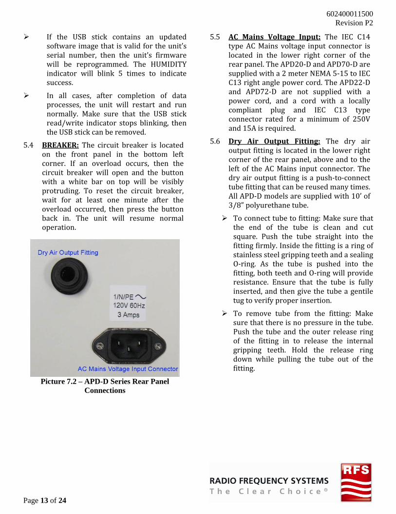
If the USB stick contains an updated software image that is valid for the unit’s serial number, then the unit’s firmware will be reprogrammed. The HUMIDITY indicator will blink 5 times to indicate success. In all cases, after completion of data processes, the unit will restart and run normally. Make sure that the USB stick read/write indicator stops blinking, then the USB stick can be removed. 5.4 BREAKER: The circuit breaker is located on the front panel in the bottom left corner. If an overload occurs, then the circuit breaker will open and the button with a white bar on top will be visibly protruding. To reset the circuit breaker, wait for at least one minute after the overload occurred, then press the button back in. The unit will resume normal operation.
Picture 7.2 – APD-D Series Rear Panel
Connections
5.5 AC Mains Voltage Input: The IEC C14 type AC Mains voltage input connector is located in the lower right corner of the rear panel. The APD20-D and APD70-D are supplied with a 2 meter NEMA 5-15 to IEC C13 right angle power cord. The APD22-D and APD72-D are not supplied with a power cord, and a cord with a locally compliant plug and IEC C13 type connector rated for a minimum of 250V and 15A is required. 5.6 Dry Air Output Fitting: The dry air output fitting is located in the lower right corner of the rear panel, above and to the left of the AC Mains input connector. The dry air output fitting is a push-to-connect tube fitting that can be reused many times. All APD-D models are supplied with 10’ of 3/8” polyurethane tube. To connect tube to fitting: Make sure that the end of the tube is clean and cut square. Push the tube straight into the fitting firmly. Inside the fitting is a ring of stainless steel gripping teeth and a sealing O-ring. As the tube is pushed into the fitting, both teeth and O-ring will provide resistance. Ensure that the tube is fully inserted, and then give the tube a gentile tug to verify proper insertion. To remove tube from the fitting: Make sure that there is no pressure in the tube. Push the tube and the outer release ring of the fitting in to release the internal gripping teeth. Hold the release ring down while pulling the tube out of the fitting.
602400011500 Revision P2
Page 14 of 24
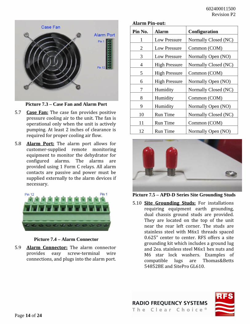
Picture 7.3 – Case Fan and Alarm Port 5.7 CaseFan: The case fan provides positive pressure cooling air to the unit. The fan is operational only when the unit is actively pumping. At least 2 inches of clearance is required for proper cooling air flow. 5.8 Alarm Port: The alarm port allows for customer-supplied remote monitoring equipment to monitor the dehydrator for configured alarms. The alarms are provided using 1 Form C relays. All alarm contacts are passive and power must be supplied externally to the alarm devices if necessary.
Picture 7.4 – Alarm Connector 5.9 Alarm Connector: The alarm connector provides easy screw-terminal wire connections, and plugs into the alarm port.
AlarmPin‐out:
Pin No. Alarm Configuration
1 Low Pressure Normally Closed (NC)
2 Low Pressure Common (COM)
3 Low Pressure Normally Open (NO)
4 High Pressure Normally Closed (NC)
5 High Pressure Common (COM)
6 High Pressure Normally Open (NO)
7 Humidity Normally Closed (NC)
8 Humidity Common (COM)
9 Humidity Normally Open (NO)
10 Run Time Normally Closed (NC)
11 Run Time Common (COM)
12 Run Time Normally Open (NO)
Picture 7.5 – APD-D Series Site Grounding Studs 5.10 Site Grounding Studs: For installations requiring equipment earth grounding, dual chassis ground studs are provided. They are located on the top of the unit near the rear left corner. The studs are stainless steel with M6x1 threads spaced 0.625” center to center. RFS offers a site grounding kit which includes a ground lug and 2ea. stainless steel M6x1 hex nuts and M6 star lock washers. Examples of compatible lugs are Thomas&Betts 54852BE and SitePro GL610.
602400011500 Revision P2
Page 15 of 24
6 MAINTENANCEIf properly installed and operated, the Dehydrator will not require any maintenance for the length of the warranty period. After that, the only preventative maintenance requirements are a check of the compressor’s input air filter element, and dust & debris removal once per year. 6.1 Taking the Unit Out of Service and
RemovingtheLid:6.1.1 Disconnect the input power cord from the rear panel of the unit. 6.1.2 Close any isolation valves in the distribution system to hold the pressurized dry air in the system. 6.1.3 Disconnect the 3/8” air tube from the rear panel of the unit. (See section 5.6). 6.1.4 If present, disconnect the site ground lug from the top of the unit. 6.1.5 If present, disconnect the alarm connector from the unit’s alarm port. 6.1.6 Move the unit to a flat work surface. 6.1.7 Remove all screws in the unit’s lid. Carefully lift the lid no more than 4 inches, then pivot the lid towards the fan and set it on the work surface.
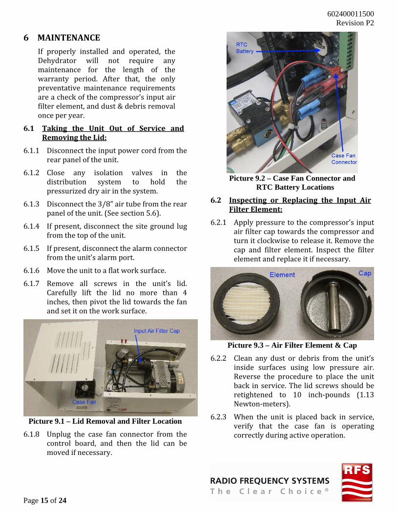
Picture 9.1 – Lid Removal and Filter Location 6.1.8 Unplug the case fan connector from the control board, and then the lid can be moved if necessary.
Picture 9.2 – Case Fan Connector and
RTC Battery Locations
6.2 Inspecting or Replacing the Input AirFilterElement:6.2.1 Apply pressure to the compressor’s input air filter cap towards the compressor and turn it clockwise to release it. Remove the cap and filter element. Inspect the filter element and replace it if necessary.
Picture 9.3 – Air Filter Element & Cap 6.2.2 Clean any dust or debris from the unit’s inside surfaces using low pressure air. Reverse the procedure to place the unit back in service. The lid screws should be retightened to 10 inch-pounds (1.13 Newton-meters). 6.2.3 When the unit is placed back in service, verify that the case fan is operating correctly during active operation.

602400011500 Revision P2
Page 16 of 24
6.3 ReplacingtheRTCBackupBattery:The battery should last many years. It is only used to maintain the unit’s Real-Time Clock (RTC) when the unit is not energized. After replacement, the RTC date and time should be reset. Refer to Picture 9.2. 6.3.1 Remove the old battery by gently lifting the retaining clip. The battery should slide out of the holder easily. 6.3.2 Install the new battery by pushing it under the clip until it snaps into the holder. 6.3.3 To reprogram the RTC date and time, a PC and a USB2.0 compliant memory device formatted as FAT32 with a single partition are required. 6.3.4 Create a new text file (i.e. with Notepad) and name it “SetClock.txt”. Two lines are required: Line 1 format: MM‐dd‐yyyy,x
MM: 2-digit month dd: 2-digit day yyyy: 4-digit year x: Single digit day of week (Sunday=1) Line 2 format: HH:mm:ss HH: 2-digit hour (24H format) mm: 2-digit minute ss: 2-digit second
Picture 9.4 – SetClock.txt Notepad Example
NOTE: Once the “SetClock.txt” file has been created, it is important to follow the steps below as quickly as possible to ensure a minimum RTC time error exists.
6.3.5 Save the “SetClock.txt” file on the USB device, and then move the USB device to the dehydrator’s front panel USB port. 6.3.6 To update the RTC, cycle power on the dehydrator using the power cord. 6.3.7 The dehydrator’s RUN TIME indicator will flash as a log file is written to the USB device. Then the RTC date and time will be updated. 6.3.8 The dehydrator’s LOW PRESSURE indicator will flash 5 times (once per second) to indicate successful RTC update. 6.3.9 The unit will then start normally. 6.4 Replacing the Lid & Placing the Unit
BackInService:6.4.1 Refer to Picture 9.1 and Picture 9.2. Place the lid next to the unit, fan down. Connect the case fan connector to the control board’s fan header, wires facing in. 6.4.2 Pivot the lid onto the unit, making sure not to pull or bind the fan wires. 6.4.3 Replace the lid screws. Insert all loosely at first, and then torque each screw to 10 inch-pounds (1.13 Newton-meters). 6.4.4 Replace the unit in its original installation location. If present, reattach the alarm port connector. If present, reconnect the site ground stud. Reconnect the 3/8” air tube to the unit’s output fitting on the rear panel. (See section 5.6). 6.4.5 Open any distribution system valves that were closed when the unit was removed. 6.4.6 Plug the unit in and verify that it starts and runs normally. Verify that the case fan is operating correctly.
602400011500 Revision P2
Page 17 of 24
7 REPLACEMENTPARTSANDACCESSORIES
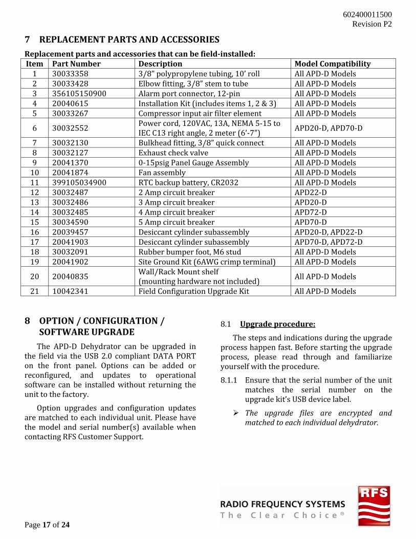
Replacementpartsandaccessoriesthatcanbefield‐installed:Item PartNumber Description ModelCompatibility1 30033358 3/8” polypropylene tubing, 10’ roll All APD-D Models 2 30033428 Elbow fitting, 3/8” stem to tube All APD-D Models 3 356105150900 Alarm port connector, 12-pin All APD-D Models 4 20040615 Installation Kit (includes items 1, 2 & 3) All APD-D Models 5 30033267 Compressor input air filter element All APD-D Models 6 30032552 Power cord, 120VAC, 13A, NEMA 5-15 to IEC C13 right angle, 2 meter (6’-7”) APD20-D, APD70-D 7 30032130 Bulkhead fitting, 3/8” quick connect All APD-D Models 8 30032127 Exhaust check valve All APD-D Models 9 20041370 0-15psig Panel Gauge Assembly All APD-D Models 10 20041874 Fan assembly All APD-D Models 11 399105034900 RTC backup battery, CR2032 All APD-D Models 12 30032487 2 Amp circuit breaker APD22-D 13 30032486 3 Amp circuit breaker APD20-D 14 30032485 4 Amp circuit breaker APD72-D 15 30034590 5 Amp circuit breaker APD70-D 16 20039457 Desiccant cylinder subassembly APD20-D, APD22-D 17 20041903 Desiccant cylinder subassembly APD70-D, APD72-D 18 30032091 Rubber bumper foot, M6 stud All APD-D Models 19 20041902 Site Ground Kit (6AWG crimp terminal) All APD-D Models 20 20040835 Wall/Rack Mount shelf (mounting hardware not included) All APD-D Models 21 10042341 Field Configuration Upgrade Kit All APD-D Models 8 OPTION/CONFIGURATION/
SOFTWAREUPGRADEThe APD-D Dehydrator can be upgraded in the field via the USB 2.0 compliant DATA PORT on the front panel. Options can be added or reconfigured, and updates to operational software can be installed without returning the unit to the factory. Option upgrades and configuration updates are matched to each individual unit. Please have the model and serial number(s) available when contacting RFS Customer Support.
8.1 Upgradeprocedure: The steps and indications during the upgrade process happen fast. Before starting the upgrade process, please read through and familiarize yourself with the procedure. 8.1.1 Ensure that the serial number of the unit matches the serial number on the upgrade kit’s USB device label. The upgrade files are encrypted and
matchedtoeachindividualdehydrator.

602400011500 Revision P2
Page 18 of 24
8.1.2 Plug the USB device into the dehydrator’s front panel USB connector and cycle the unit’s power. The unit’s POWER indicator will be illuminated throughout this process. The following indications will occur in order: a. The unit’s current operational log file will be written to the USB device. During this operation, the unit’s RUN TIME indicator will flash. b. The latest operational software (E_Image.s19) will be written to the unit. The unit’s RUN TIME, HUMIDITY and HIGH PRESSURE indicators will illuminate solid and the LOW PRESSURE indicator will flash during this process. c. When programming is complete, then the LOW PRESSURE and COMPRESSOR indicators will illuminate solid momentarily and then all indicators will extinguish. i. If the unit already has the latestoperational software installed, then theaboveprocesswillbeskipped.d. The upgraded configuration (eeprom.eep) will be written to the unit. There is no indication of this process occurring because it happens very quickly. i. If the configurationon theUSBdevicematches the unit’s current configuration,thenthisprocesswillbeskipped.e. Once all programming is complete, the following indications will occur, and are used to determine successful programming. If more than one condition exists, then the indicators will flash together. i. The HUMIDITY indicator flashes 5
times to indicate successful firmwareupdate.
j. TheHIGH PRESSURE indicator flashes5 times to indicate successfulconfigurationupgrade.
8.1.3 The unit will then restart normally (indicators light top to bottom, then extinguish bottom to top). The USB device can now be removed. 8.1.4 If the HIGH PRESSURE indicator fails to flash 5 times during this process, then the configuration upgrade was not successful. In this case, please do the following: a. Plug the upgrade USB device into the dehydrator’s front panel USB connector and cycle the unit’s power again. A new log file will be written to the USB device b. After the unit restarts normally, remove the USB device from the unit. There should be at least two files on the USB device with 5-digit numeric names and a “.BIN” suffix. These files need to be provided to RFS Applications Engineering for assistance in determining why the upgrade failed. The unit’s current serial number and model number, as well as the upgrade serial number and model number should also be provided. 8.1.5 Upon successful completion of the upgrade process, place the provided upgrade product label over the existing product label on the dehydrator’s rear panel.
602400011500 Revision P2
Page 19 of 24
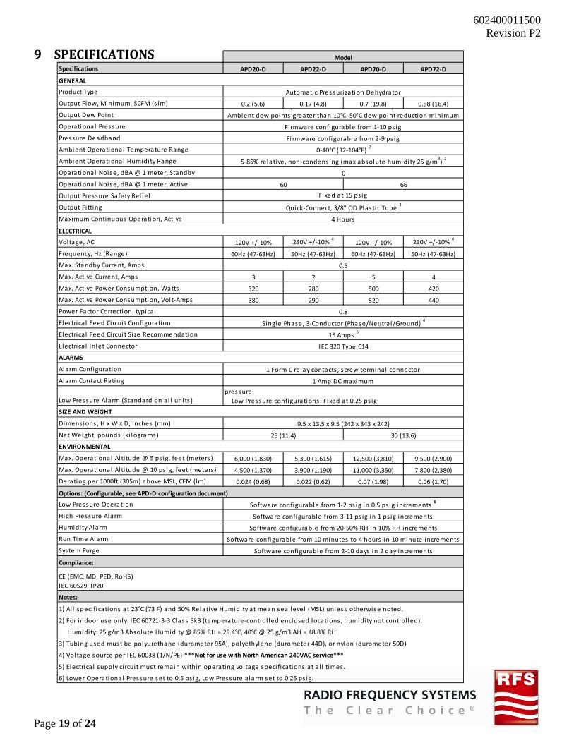
9 SPECIFICATIONS Specifications APD20‐D APD22‐D APD70‐D APD72‐D
GENERAL
Product Type
Output Flow, Minimum, SCFM (s lm) 0.2 (5.6) 0.17 (4.8) 0.7 (19.8) 0.58 (16.4)
Output Dew Point
Operational Pressure
Pressure Deadband
Ambient Operational Temperature Range
Ambient Operational Humidity Range
Operational Noise, dBA @ 1 meter, Standby
Operational Noise, dBA @ 1 meter, Active
Output Pressure Safety Rel ief
Output Fi tting
Maximum Continuous Operation, Active
ELECTRICAL
Voltage, AC 120V +/‐10% 230V +/‐10% 4
120V +/‐10% 230V +/‐10% 4
Frequency, Hz (Range) 60Hz (47‐63Hz) 50Hz (47‐63Hz) 60Hz (47‐63Hz) 50Hz (47‐63Hz)
Max. Standby Current, Amps
Max. Active Current, Amps 3 2 5 4
Max. Active Power Consumption, Watts 320 280 500 420
Max. Active Power Consumption, Volt‐Amps 380 290 520 440
Power Factor Correction, typica l
Electrical Feed Circui t Configuration
Electrical Feed Circui t Size Recommendation
Electrical Inlet Connector
ALARMS
Alarm Configuration
Alarm Contact Rating
Low Pressure Alarm (Standard on al l units )
SIZE AND WEIGHT
Dimensions , H x W x D, inches (mm)
Net Weight, pounds (ki lograms)
ENVIRONMENTAL
Max. Operational Alti tude @ 5 ps ig, feet (meters ) 6,000 (1,830) 5,300 (1,615) 12,500 (3,810) 9,500 (2,900)
Max. Operational Alti tude @ 10 ps ig, feet (meters) 4,500 (1,370) 3,900 (1,190) 11,000 (3,350) 7,800 (2,380)
Derating per 1000ft (305m) above MSL, CFM (lm) 0.024 (0.68) 0.022 (0.62) 0.07 (1.98) 0.06 (1.70)
Low Pressure Operation
High Pressure Alarm
Humidity Alarm
Run Time Alarm
System Purge
Model
Automatic Pressurization Dehydrator
pressure
Low Pressure configurations : Fixed at 0.25 ps ig
1 Form C relay contacts , screw terminal connector
1 Amp DC maximum
4 Hours
p p
Ambient dew points greater than 10°C: 50°C dew point reduction minimum
Firmware configurable from 2‐9 ps ig
Fi rmware configurable from 1‐10 ps ig
66
0
0.5
Fixed at 15 ps ig
30 (13.6)
5‐85% relative, non‐condens ing (max absolute humidity 25 g/m3) 2
0‐40°C (32‐104°F) 2
Quick‐Connect, 3/8" OD Plas tic Tube 3
9.5 x 13.5 x 9.5 (242 x 343 x 242)
25 (11.4)
15 Amps 5
0.8
IEC 320 Type C14
Single Phase, 3‐Conductor (Phase/Neutra l/Ground) 4
60
Software configurable from 1‐2 ps ig in 0.5 ps ig increments 6
Options: (Configurable, see APD‐D configuration document)
CE (EMC, MD, PED, RoHS)
IEC 60529, IP20
Notes:
4) Voltage source per IEC 60038 (1/N/PE) ***Not for use with North American 240VAC service***
1) Al l speci fications at 23°C (73 F) and 50% Relative Humidity at mean sea level (MSL) unless otherwise noted.
Software configurable from 3‐11 ps ig in 1 ps ig increments
Software configurable from 20‐50% RH in 10% RH increments
Software configurable from 10 minutes to 4 hours in 10 minute increments
Compliance:
Software configurable from 2‐10 days in 2 day increments
5) Electrica l supply ci rcui t must remain within operating voltage speci fications at al l times.
2) For indoor use only. IEC 60721‐3‐3 Class 3k3 (temperature‐control led enclosed locations , humidity not control led),
Humidity: 25 g/m3 Absolute Humidity @ 85% RH = 29.4°C, 40°C @ 25 g/m3 AH = 48.8% RH
3) Tubing used must be polyurethane (durometer 95A), polyethylene (durometer 44D), or nylon (durometer 50D)
6) Lower Operational Pressure set to 0.5 ps ig, Low Pressure alarm set to 0.25 ps ig.

602400011500 Revision P2
Page 20 of 24
10 MODELCONFIGURATION

602400011500 Revision P2
Page 21 of 24
11 RUNTIMECALCULATIONSThe following calculation can be used to estimate the amount of run time an APD-D series dehydrator will take to pressurize a given volume. This calculation is a simplified best-fit estimate. Actual pump times will be dependent on many variables, such as: APD-D flow variations. Each dehydrator has flow variations. The specifications indicate the minimum flow for each model. APD-D service condition. How old the unit is, how well maintained. APD-D environmental conditions. The environment in which the dehydrator is operating has an effect on its performance. System flow restrictions. Any restrictions in the distribution system which the dehydrator is pressurizing can have pronounced performance consequences. System air tightness. Any leaks in the distribution system which the dehydrator is pressurizing can have pronounced performance consequences. And other variables…
= −.
= − + − = Total system run time in minutes = Volume of system in m3, ft3, gallons, or liters = Volume conversion factor to cubic feet = 35.314 for Volume in cubic meters (m3) = 1.0 for Volume in cubic feet (ft3) = 0.1337 for Volume in gallons = 0.0353 for Volume in liters = Lower operational pressure, psig (where compressor starts) = Upper operational pressure, psig (where compressor stops) = Effective flow (linearized average) = Dehydrator output flow, CFM (cubic feet per minute @ MSL, 0 psig, 23° Celsius, 50%RH) = 0.20 for APD20-D = 0.17 for APD22-D = 1.0 for APD70-D = 0.65 for APD72-D = Flow correction factor for pressures above 0 psig = 0.91 for APD20-D, APD22-D, APD72-D = 0.92 for APD70-D = Elevation AMSL (above mean sea level) in feet
= Elevation correction factor for flow = 0.000024 for APD20-D = 0.000022 for APD22-D = 0.000070 for APD70-D = 0.000060 for APD72-D = Pressure correction factor for elevation = 0.94 ExcelFormulas:Assume APD20-D with 33 meters of E65 elliptical waveguide. calculated in cell A10: =((A5*A6^A4-A7*A8*A9^A4)+(A5*A6^A3-A7*A8*A9^A3))/2 calculated in cell A11 in fractional minutes: =A2*A1*((A4-A3)/14.696)/A10 calculated in cell A12 in [h:mm:ss] format. =INT(A11/60)&":"&TEXT(INT(MOD(A11,60)),"00")&":"&TEXT(INT(MOD(A11*60,60)),"00")

602400011500 Revision P2
Page 22 of 24
12 TRANSMISSIONLINEVOLUMESThe tables below contain estimated volume per linear unit for the most common transmission lines. RFSEllipticalWaveguidevolumes:Waveguide
Type Liters per
meter (l/m) Cubic foot per
foot (ft3/ft) E38 2.58 0.0275 E46 1.83 0.0196 E60 1.05 0.0113 E65 0.840 0.00904 EP70 0.718 0.00773 E78 0.590 0.00635 EP100 0.368 0.00396 E105 0.292 0.00314 E130 0.212 0.00229 E150 0.153 0.00165 E185 0.0797 0.000858 E220 0.0543 0.000585 E250 0.0374 0.000403 E300 0.0236 0.000255 EO38 0.0636 0.000685 E380 0.0130 0.000140
RFSAirDielectricCoaxialcablevolumes:Cable Type
Liters per meter (l/m)
Cubic foot per foot (ft3/ft)
HCA38 0.107 0.00115 HCA12 0.134 0.00144 ICA12 0.131 0.00142 HCA58 0.252 0.00272 HCA78 0.447 0.00481 HCA118 0.753 0.00810 HCA158 1.43 0.0154 HCA214 2.11 0.0227 HCA295 2.91 0.0313 HCA300 3.44 0.0371 HCA400 4.79 0.0516 HCA495 7.79 0.0839 HCA550 12.86 0.138 HCA618 17.09 0.184 HCA800 30.15 0.325 HCA900 40.16 0.432
Commscope/AndrewEllipticalWaveguidevolumes:
Waveguide Type
Liters per meter (l/m)
Cubic foot per foot (ft3/ft)
EW17 6.60 0.0710 EW20 5.62 0.0605 EW37 1.96 0.0211 EW43 1.69 0.0182 EW52 1.045 0.0112 EW63 0.855 0.0092 EW64 0.725 0.0078 EW77 0.585 0.0063 EW85 0.39 0.0042 EW90 0.334 0.0036 EW127A 0.25 0.0027 EW132-137 0.167 0.0018 EW132-140 0.167 0.0018 EW132-144 0.167 0.0018
EIARectangularWaveguide(TE10mode)Volumes:
Waveguide Type
Liters per meter (l/m)
Cubic foot per foot (ft3/ft)
WR340 / WG9A 3.73 0.0401 WR284 / WG10 2.46 0.0264 WR229 / WG11A 1.70 0.0183 WR187 / WG12 1.05 0.0113 WR159 / WG13 0.816 0.00878 WR137 / WG14 0.551 0.00593 WR112 / WG15 0.360 0.00387 WR90 / WG16 0.232 0.00250 WR75 / WG17 0.181 0.00195 WR62 / WG18 0.125 0.00134 WR51 / WG19 0.0839 0.000903 WR42 / WG20 0.0461 0.000496 WR28 / WG22 0.0253 0.000272 WR22 / WG23 0.0162 0.000174 WR19 / WG24 0.0114 0.000123 WR15 / WG25 0.00707 0.0000761 WR12 / WG26 0.00480 0.0000517
602400011500 Revision P2
Page 23 of 24
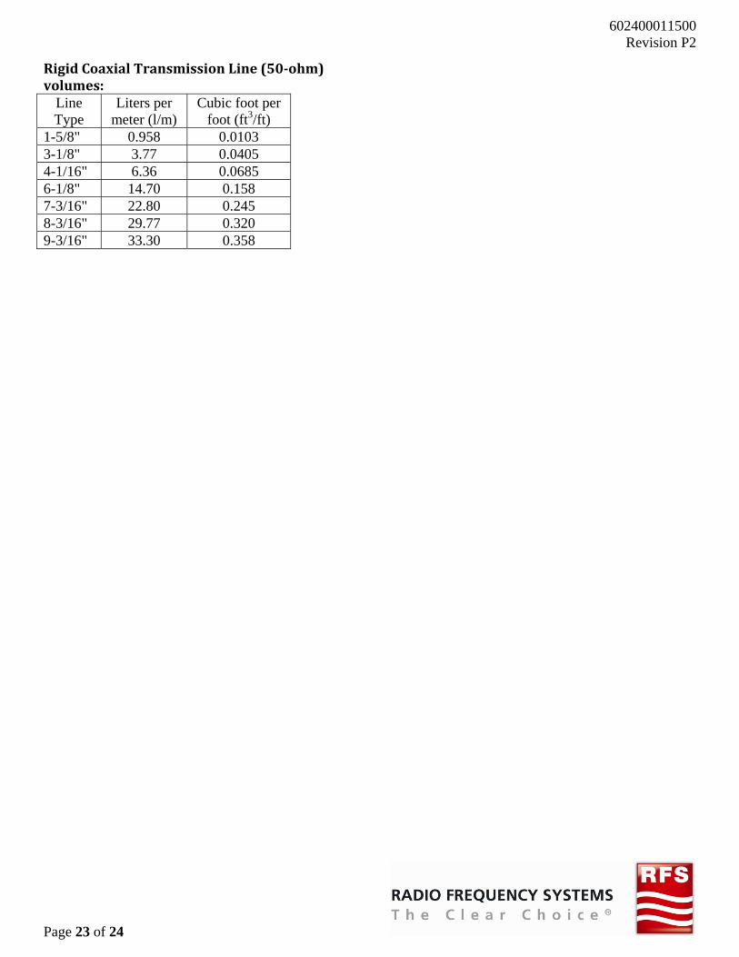
RigidCoaxialTransmissionLine(50‐ohm)volumes:
Line Type
Liters per meter (l/m)
Cubic foot per foot (ft3/ft)
1-5/8" 0.958 0.0103 3-1/8" 3.77 0.0405 4-1/16" 6.36 0.0685 6-1/8" 14.70 0.158 7-3/16" 22.80 0.245 8-3/16" 29.77 0.320 9-3/16" 33.30 0.358

Page
13
e 24 of 24
CEDECLAARATIONOFCONFFORMITY
6002400011500Revision P2
0 2