practical aspects of fuel injection equipment operation and service
TRANSCRIPT

Service Instruction
Practical Aspects of Fuel Injection Equipment Operation and Service
Manual 55152
This document, and more, is available for download from Martin's Marine Engineering Page - www.dieselduck.net

DEFINITIONS
This is the safety alert symbol. It is used to alert you to potential personal injury hazards. Obey all safety messages that follow this symbol to avoid possible injury or death.
• DANGER—Indicates a hazardous situation which, if not avoided, will result in death or serious injury.
• WARNING—Indicates a hazardous situation which, if not avoided, could result in death or serious injury.
• CAUTION—Indicates a hazardous situation which, if not avoided, could result in minor or moderate injury.
• NOTICE—Indicates a hazard that could result in property damage only (including damage to the control).
• IMPORTANT—Designates an operating tip or maintenance suggestion.
The engine, turbine, or other type of prime mover should be equipped with an overspeed shutdown device to protect against runaway or damage to the prime mover with possible personal injury, loss of life, or property damage.
The overspeed shutdown device must be totally independent of the prime mover control system. An overtemperature or overpressure shutdown device may also be needed for safety, as appropriate.
Read this entire manual and all other publications pertaining to the work to be performed before installing, operating, or servicing this equipment. Practice all plant and safety instructions and precautions. Failure to follow instructions can cause personal injury and/or property damage.
This publication may have been revised or updated since this copy was produced. To verify that you have the latest revision, be sure to check the Woodward website:
www.woodward.com/pubs/current.pdf The revision level is shown at the bottom of the front cover after the publication number. The latest version of most publications is available at:
www.woodward.com/publications If your publication is not there, please contact your customer service representative to get the latest copy.
Any unauthorized modifications to or use of this equipment outside its specified mechanical, electrical, or other operating limits may cause personal injury and/or property damage, including damage to the equipment. Any such unauthorized modifications: (i) constitute "misuse" and/or "negligence" within the meaning of the product warranty thereby excluding warranty coverage for any resulting damage, and (ii) invalidate product certifications or listings.
To prevent damage to a control system that uses an alternator or battery-charging device, make sure the charging device is turned off before disconnecting the battery from the system.
To prevent damage to electronic components caused by improper handling, read and observe the precautions in Woodward manual 82715, Guide for Handling and Protection of Electronic Controls, Printed Circuit Boards, and Modules.
Woodward Governor Company reserves the right to update any portion of this publication at any time. Information provided by Woodward Governor Company is believed to be correct and reliable. However, no responsibility is assumed by Woodward Governor Company unless otherwise expressly undertaken.
© Woodward 1998 All Rights Reserved
This document, and more, is available for download from Martin's Marine Engineering Page - www.dieselduck.net

Manual 55152 Fuel Injection Equipment Operation & Service
Woodward 1
Contents
PRACTICAL ASPECTS OF FUEL INJECTION EQUIPMENT OPERATION AND SERVICE ..................................................................................................... 2 1. Introduction ......................................................................................................... 2 2. Fuel Pumps ........................................................................................................ 2 3. Pump Service and Operational Problems .......................................................... 4 4. Fuel Pump Rework ............................................................................................. 7 5. Injectors ............................................................................................................ 10 6. Injector Removal and Examination ................................................................... 14 7. Product Identification ........................................................................................ 21 8. Health and Safety ............................................................................................. 22
Illustrations and Tables Figure 1. Pump Designs ......................................................................................... 3 Figure 2. Pump (Large) Design .............................................................................. 3 Figure 3. Injector Designs ..................................................................................... 11 Figure 4. Blow-back Condition ............................................................................. 11 Figure 5. Early Stage of Cold Corrosion ............................................................... 12 Figure 6. Advanced Stage of Cold Corrosion ....................................................... 13 Figure 7. Basic Nozzle Details ............................................................................. 18 Figure 8. Nozzle Damaged by Abuse ................................................................... 19 Figure 9. Additional Tools and Fixtures ................................................................ 23
This document, and more, is available for download from Martin's Marine Engineering Page - www.dieselduck.net
Fuel Injection Equipment Operation & Service Manual 55152
2 Woodward
Practical Aspects of Fuel Injection Equipment Operation and Service
It is mandatory that before carrying out any work on the equipment covered by this manual, the customer or user satisfactorily complete a Woodward-recognized training course. Training courses can be made available by Woodward or some of its Distributors if required.
Important health and safety considerations apply when working on Woodward fuel injection equipment. All work carried out must be compliant with service bulletin 01539 (old number 308), Safe Handling and Use of Woodward Diesel Systems Equipment.
1. Introduction Cooperation between fuel injection equipment designers and engine designers is close during the early stages of engine design and development. The physical size of the fuel pump and injector has often been limited by the engine design, particularly in the case where the installation has been subjected to a series of engine up-rating programs. In some situations, smaller units have been required to handle larger deliveries and up to double the speeds that were originally considered prohibitive a few years before. This situation has often imposed high loadings, both mechanical and thermal, on the fuel injection equipment, and special operating and service techniques, along with certain modifications, have been required to ensure satisfactory and economic operation. Various service hazards encountered on the earlier larger diesel engines are described in addition to the changes in current fuel injection equipment that have resulted from both this and the policy of striving for continual improvement. This document also outlines, in a series of separate sections, routine fuel injection equipment inspection, facilities and equipment needed, critical appraisal during fuel injection equipment examination, servicing, and testing.
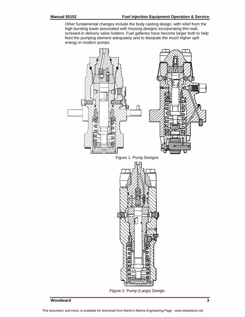
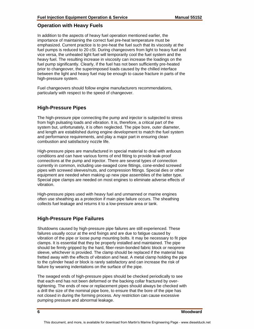
2. Fuel Pumps Requirements and General Design Features Figure 1 shows two typical, well established medium and large fuel pumps. Both have a relatively low peak pressure capability of 1200 bar. Later designs generally use closed-bore pumping barrels with an integral delivery valve above the bore outlet and are used at pressures up to 2000 bar (validated to around 2600 bar during development). Figure 2 shows such a design for a large fuel pump. Improved, cleaner materials provide increased safety factors in terms of barrel strength and sealing. Lapped or fine-ground sealing faces have largely superseded thin tin-plated joint washers between the delivery valve seat and its holder (originally copper joints), which were prone to ‘tracking’ across the surfaces.
This document, and more, is available for download from Martin's Marine Engineering Page - www.dieselduck.net
Manual 55152 Fuel Injection Equipment Operation & Service
Woodward 3
Other fundamental changes include the body casting design, with relief from the high bursting loads associated with housing designs incorporating thin-wall, screwed-in delivery valve holders. Fuel galleries have become larger both to help feed the pumping element adequately and to dissipate the much higher spill energy in modern pumps.
Figure 1. Pump Designs
Figure 2. Pump (Large) Design
This document, and more, is available for download from Martin's Marine Engineering Page - www.dieselduck.net

Fuel Injection Equipment Operation & Service Manual 55152
4 Woodward
3. Pump Service and Operational Problems Fuel Admission The fuel feed arrangement to the pump when running on distillate (light) fuel is usually simple and trouble-free but can sometimes be critical on dual-fuel engines, where it is necessary to maintain regularity of injection at very low fuelings. A constant supply pressure is essential. It is also usually necessary to provide a continuous through-flow of fuel to avoid aeration and resultant ‘air locking’ at the pump inlet. Pumps are provided with fuel supply inlet and outlet connections for operation with residual (heavy) fuels. Aeration problems are overcome but, more important, a quicker changeover from heavy to light fuel before shut down (and vice versa) on starting, can be achieved. It is essential to supply the light fuel at the same pressure as the heavy fuel, if vapor locking on changeover before shutdown is to be avoided. Such vapor locking is due to water droplets in the heavy fuel flashing into steam when reduced to the lower feed pressure of the light fuel. The light fuel temperature can be an important factor on heavy fuel installations. Extremely cold light fuel will locally chill the heated heavy fuel, increasing its viscosity and thereby overloading the fuel pumps and drive system. Leakage and Lubrication Leakage from the fuel pump was, at one time, a serious problem, causing the dilution of lubricating oil by fuel oil. It was overcome by the introduction of a ‘barrier groove’ and drain hole in the pump element, thus allowing leaking fuel to be returned to the fuel gallery. However, such reduction in element shank leakage can result in inadequate lubrication of the components in the lower part of the pump when operating with heavy fuels. The adverse effects of ‘dry’ operation can be observed as rapid wear of the plunger dog, control sleeve slot, and tappet bore at the base of the pump housing. Owing to the incompatibility of many engine lube oils with the fuel oil, causing lacquer formation at any close-running interfaces (such as plunger/barrel), it is no longer recommended that lube oil be supplied to the barrel bore to lubricate the clearance, especially on pumps used with pre-heated heavy fuel. To prevent gumming-up of the control sleeve/rod and lower end parts with congealed heavy fuel, either occasional 'shots' of lube oil or of distillate fuel or gasoil may be fed to this area of the pump. This helps both lubricate and keep the lower end parts clean. Some engine manufacturers provide metering pumps and pipework for this purpose. An O-ring seal is a convenient and reliable means of providing a static seal at various points in the fuel pump. It is important that the correct type and hardness of elastomer be selected for the various applications. A conventional low-nitrile compound is suitable for use with distillate fuel, but viton seals are needed for heavy fuels requiring a preheat temperature of up to 150 °C (or more 300 °F) (such as IFO 380 [35 cSt @ 100 °C] viscosity-Class G). Frequent renewal may be necessary for some arduous applications. Close attention is required, and seals should be changed at specified service intervals.
This document, and more, is available for download from Martin's Marine Engineering Page - www.dieselduck.net

Manual 55152 Fuel Injection Equipment Operation & Service
Woodward 5
Corrosion High water content in the fuel can be experienced with heavy fuel operation because of the relatively longer time required for settling and increased opportunities for condensation in tanks. It can also be a problem, irrespective of fuel type, in coasters, ferries, and trawlers, where the risk of contamination by sea water through tank inlets and vents is greater. Water entrained in the fuel can cause two forms of corrosion: 1. On the external surface of the pump element when the fuel does not reach a
temperature above the boiling point of water. Corrosion becomes evident as rusting of the parts. This should be treated as a warning that the fuel pre-treatment is inadequate, and remedial action should be taken.
2. Under fuel feed pressure, the boiling point of the entrained water is elevated
and, although the fuel temperature may exceed 100 °C (212 °F), the water is not boiled off. However, as the fuel leaks down the shank of the pump plunger (and of the nozzle needle), the pressure is reduced toward atmospheric pressure, and the entrained water flashes into steam. This results in corrosion of the plunger and barrel, and produces black iron oxide on the surfaces. The initial glazed black appearance soon deteriorates to a matt black as the surface is destroyed. The fine clearance is lost, leakage is increased, and pump delivery drops.
Critical Wear of Pump Components Pump elements will wear with time, but this wear is usually uniform throughout a set of pumps, and pump-to-pump output balance will remain acceptable for normal applications. The degree of wear may be judged by comparing the full-load control-rod settings with the settings recorded on the original engine test sheets. The control-rod setting to obtain a reliable start on the smaller engines is also a useful indication of pump condition. Difficulty in priming individual pumps may indicate a badly worn delivery valve or a leaking high-pressure seal. Wear of the pump control mechanism is very important but not easily located since it can occur at many points in the system. Modern pumps generally use surface-hardened control sleeves and therefore wear is not usually a problem. Wear of the plunger pin or dog and the slot in the control sleeve is critical; however, if wear has occurred, control of the pump delivery is adversely affected. Control rod and control sleeve teeth wear can lead to stiffness to the point where it may be difficult to stop the engine. It should also be noted that heavy fuel which has dried on the control rod—after protracted running at a steady load—can also cause a control rod to jam or become difficult to move. Proper attention should be given to the control linkage attached to the control rod, especially safety spring settings and clevis pin wear.
This document, and more, is available for download from Martin's Marine Engineering Page - www.dieselduck.net
Fuel Injection Equipment Operation & Service Manual 55152
6 Woodward
Operation with Heavy Fuels In addition to the aspects of heavy fuel operation mentioned earlier, the importance of maintaining the correct fuel pre-heat temperature must be emphasized. Current practice is to pre-heat the fuel such that its viscosity at the fuel pumps is reduced to 20 cSt. During changeovers from light to heavy fuel and vice versa, the unheated light fuel will temporarily cool the fuel system and the heavy fuel. The resulting increase in viscosity can increase the loadings on the fuel pump significantly. Clearly, if the fuel has not been sufficiently pre-heated prior to changeover, the superimposed loads caused by the chilled interface between the light and heavy fuel may be enough to cause fracture in parts of the high-pressure system. Fuel changeovers should follow engine manufacturers recommendations, particularly with respect to the speed of changeover. High-Pressure Pipes The high-pressure pipe connecting the pump and injector is subjected to stress from high pulsating loads and vibration. It is, therefore, a critical part of the system but, unfortunately, it is often neglected. The pipe bore, outer diameter, and length are established during engine development to match the fuel system and performance requirements, and play a major part in ensuring clean combustion and satisfactory nozzle life. High-pressure pipes are manufactured in special material to deal with arduous conditions and can have various forms of end fitting to provide leak-proof connections at the pump and injector. There are several types of connection currently in common, including use-swaged cone fittings, cone-ended screwed pipes with screwed sleeves/nuts, and compression fittings. Special dies or other equipment are needed when making up new pipe assemblies of the latter type. Special pipe clamps are needed on most engines to eliminate adverse effects of vibration. High-pressure pipes used with heavy fuel and unmanned or marine engines often use sheathing as a protection if main pipe failure occurs. The sheathing collects fuel leakage and returns it to a low-pressure area or tank. High-Pressure Pipe Failures Shutdowns caused by high-pressure pipe failures are still experienced. These failures usually occur at the end fixings and are due to fatigue caused by vibration of the pipe or loose pump mounting bolts. It may be necessary to fit pipe clamps. It is essential that they be properly installed and maintained. The pipe should be firmly gripped by the hard, fiber-resin-bonded fabric block or neoprene sleeve, whichever is provided. The clamp should be replaced if the material has fretted away with the effects of vibration and heat. A metal clamp holding the pipe to the cylinder head or block is rarely satisfactory and can increase the risk of failure by wearing indentations on the surface of the pipe. The swaged ends of high-pressure pipes should be checked periodically to see that each end has not been deformed or the backing collar fractured by over-tightening. The ends of new or replacement pipes should always be checked with a drill the size of the nominal pipe bore, to ensure that the bore of the pipe has not closed in during the forming process. Any restriction can cause excessive pumping pressure and abnormal leakage.
This document, and more, is available for download from Martin's Marine Engineering Page - www.dieselduck.net

Manual 55152 Fuel Injection Equipment Operation & Service
Woodward 7
Special care must be taken when re-making or replacing a new pipe with proprietary compression-type fittings. With these fittings, high wrench (spanner) torques are not required to make a satisfactory joint. It is important that the end face of the pipe be square and that there be the correct pipe protrusion through the ring or olive before tightening the pump nut. The use of unnecessary force can malform the ring or damage the threaded connection on the pipe or injector. The engine manufacturer’s torque settings should always be observed. The high-pressure pipe should always be bent or formed to the correct shape before fitting. In particular, the ends should align with the pump and injector fittings without strain. When high-pressure pipes are stored, their ends should always be protected by tape or a blank plug in the pipe nuts. Before fitting to an engine, the pipe should be blown through with compressed air or washed with fuel oil to remove any dirt that may have entered during handling or transit.
4. Fuel Pump Rework General The procedure for dismantling the fuel pumps of conventional design is fairly obvious. It is preferable to dismantle the lower (tappet) end first. Control rod/sleeve meshing should be observed and recorded. The delivery valve holder (discharge union) will have been tightened to a specified torque. Pumps should be dismantled according to the detailed instructions provided by the engine builder or pump manufacturer. Particular care is needed when loading the tappet spring. Special tools can be purchased or can be made to facilitate dismantling. Pump Component Examination The delivery valve holder sealing face should be examined for scores or fuel tracking. If leakage has been occurring across the high-pressure seal (fiber or copper washer or tin-plated steel washer on earlier pumps), there are usually fine lines indicating the tracking of the fuel. Any leakage across high-pressure lapped faces (such as delivery valve seat to the top of the barrel) will be indicated by darker coloration of the normally clean surfaces. Even, gray/green discoloration of the steel surfaces exposed to the fuel, such as the outside diameter of the barrel, is an indication that the water content of the fuel has been high. A cracked barrel can indicate excessive pumping pressure. Possible causes are inadequately heated heavy fuel or a blockage at the nozzle, injector edge filter, pipe ends, pump delivery valve holder, etc.
This document, and more, is available for download from Martin's Marine Engineering Page - www.dieselduck.net
Fuel Injection Equipment Operation & Service Manual 55152
8 Woodward
A gray shading on the plunger surface above the helix can sometimes be seen during servicing. This is caused by spill erosion but can be ignored as long as the area does not extend down to within 2 mm of the control edge of the helix. A black stain on the lower part of the plunger diameter indicates a high water content in the fuel. The dog on the fuel pump plunger should be checked in the control sleeve slot to confirm that there has been no excessive wear which would affect the accuracy of control. For the same reason, the amount of visible wear on control rod and control sleeve teeth should be checked to see if there is any appreciable difference between those in the normal running position and those at the end of the travel. The spring coils should be examined for flats caused by a bowed spring rubbing on the bore of the fuel pump tappet or the control sleeve. The spring length should be checked against a new spare. If the old spring is outside recommended service limits (refer to manual), it should be renewed. Bright marks on the bottom of the pump tappet are made by the engine operating mechanism on the outside and by the foot of the pump plunger on the inside. These areas should be checked for heavy indentation or cracking of the surface, again refer to the service instructions. By standing the pump plunger and the lower spring plate on a dead flat surface, with the spring plate pressed firmly down, a check can be made that the plunger head is quite free to turn axially. The plate should be renewed if it tends to limit free movement of the plunger foot. The pump body should be checked for the following: • Damaged delivery valve holder inlet connection threads. • Ovality or excessive wear in the tappet bore. • Damage or indentation on flat or conical element seating surfaces. • Signs of erosion in the fuel gallery or on the erosion plugs. The plugs should
be renewed if the erosion has penetrated the face beyond specified service limits.
Pump Checking During Rebuild There are a number of simple checks to ensure that the pump has been re-assembled correctly. As a general rule, the operator can safely assume that a new element will give the correct output for any given rack setting after shimming correctly during calibration. Detailed inspection and performance checks carried out during component manufacture ensure a very high standard of interchangeability. However, careful comparison of the original component and the replacement is recommended. (Engines have been known to ‘run away’ when a set of left-hand helix elements were fitted to pumps from which a worn set of right-hand helix elements had been removed.) When rebuilding a fuel pump, after the barrel has been removed and replaced, it is advisable to carry out a pressure test to check the seating of the barrel in the suction chamber. After rebuilding the top portion of the pump, the plunger should be replaced in the barrel and retained by a pin or bridge piece across the bottom of the pump, which is otherwise left open unless specified tooling is available to do otherwise. The fuel gallery should be connected with air at a suitable pressure (such as 4–5.5 bar [60/80 psi]). The pump should then be immersed upside down in a tank of fuel oil or test oil when any leakage under the shoulder of the element (or past the O-ring on some pumps of later design) will be indicated by bubbles of escaping air.
This document, and more, is available for download from Martin's Marine Engineering Page - www.dieselduck.net

Manual 55152 Fuel Injection Equipment Operation & Service
Woodward 9
The pump manufacturer’s instructions should be followed implicitly when re-meshing control rod and sleeve (rack and pinion). An additional check to verify that tooth meshing is correct can be made by ensuring the gash (vertical slot) in the plunger aligns with the port in the barrel at the ‘stop’ control-rod position (no load). This can be observed by viewing the plunger-barrel relationship through the removed spill plug (if fitted). A `dead rack' test on calibration is mandatory for engine safety reasons. Checking of Pump Spill Cut-off Point after Rebuild Pump ‘cut-off’ point can be checked after assembly by using a mounting fixture similar to that shown in Figure 9 and connecting the pump to a small ‘gravity’ tank if a pressurized test oil source is not available. With the control rod in mid position, the tappet and plunger should be raised, slowly, by means of the depressing screw below the fixture. The flow will decrease as the top of the plunger progressively closes the port, and will stop when the port is completely sealed. This is the pump cut-off point (`static' start of injection). The position of the pump tappet should be checked in relation to the flange, and reference made to the maker’s instructions. If the pump has a ‘timing window’, the pointer or scribed line should be coincident with a line on the pump tappet. Original lines may need to be obliterated and a fresh one scribed. Dead-Rack Check (if pump calibration not possible) To confirm that the control rod and sleeve are correctly meshed, the dead-rack point can be checked and compared with a new pump. This can be done on the same mounting fixture and tank as that used for the previous test. In this test, the plunger should be raised to mid-position with the adjusting screw, and the control rod centralized. If the control rod is then moved slowly toward ‘STOP’ or ‘NO DELIVERY’, fuel will start to flow from the delivery union as soon as the vertical edge of the plunger uncovers the edge of the port. Flow will continue from then on if the control rod is further moved to the ‘Mechanical Stop’ end of its travel. It will cease again when the rod is moved from ‘STOP’ and the port is again just sealed. Dynamic Testing A special test rig is required. As certain pumps (for example, for dual-fuel applications) can only be correctly calibrated on a dynamic test rig, they must be repaired by a qualified agent of the manufacturer. Refitting the Fuel Pump The operator must ensure that the engine tappet is in the correct position to give the timing specified by the engine maker. In practice, tappets may have been adjusted up or down during engine balancing exercises, and the setting may be far from the correct position. This can result in damage to the pump. The use of an engine tappet setting gauge, as shown in Figure 9, ensures that the correct timing is achieved and is recommended. With the engine cam on the base circle, the engine tappet or pump shimming, if used, should be adjusted so that the engine tappet just touches the gauge when this is pressed firmly down on the pump mounting face, with the fuel cam rotated to the correct position for that cylinder.
This document, and more, is available for download from Martin's Marine Engineering Page - www.dieselduck.net
Fuel Injection Equipment Operation & Service Manual 55152
10 Woodward
This tappet setting ensures that: • The pump tappet will be clear of the retaining circlip at the bottom of the
stroke. • There is no risk of accidental damage by raising the plunger to a point
where it strikes the delivery valve seat. • Any further adjustment-needed to obtain the correct maximum cylinder
pressure requires minimum re-setting of the pump operating tappet (reference to engine manufacturers instructions only).
5. Injectors General Design Features Figure 3 shows a typical modern, shim-set, low-inertia injector and a large, heavy-fuel (cooled) design. While the physical size of the fuel injector has not changed significantly since the original standards and classifications were established, a slight increase in injector shank diameter has been introduced. These modifications provide more space for coolant passages and to house a larger injector spring close to the nozzle, accommodating higher nozzle operating pressures. This has reduced the inertia of moving parts by eliminating the reciprocating spring spindle. The resulting faster needle closure rate reduces the time in which combustion gases can blow back into the nozzle, preventing contamination of the internal parts. The relationship of pressure and needle movement is shown in Figure 4, which illustrates conditions of 'blow back'. It can be seen that by reducing the needle closure time, the needle valve can reach its seat before fuel pressure is reduced below cylinder gas pressure, and gas entry is thus prevented. Nozzle back-leakage is normally passed up drillings in the injector body and onto drillings in the engine cylinder head. This avoids external pipework, which can fail or leak. Vent screws and 'edge'-type filters, which were common on older designs, are not generally used today. The higher peak injection pressures and close attention to fuel filtration levels have dictated the removal of these features. Again, as a result of much higher injection pressure and hence parting loads on sealing faces, modern large injectors often use specially designed, relieved sealing faces, to maximize sealing capability. From a cost viewpoint, some modern injectors use a simple, straight 'bar' machined design. Others incorporate a side inlet connector passing through the cylinder head. The latter have the advantage of minimizing the trapped system volume and optimizing peak injection pressure against the pumping rate available, but there is an inevitable trade-off of cost against optimum design.
This document, and more, is available for download from Martin's Marine Engineering Page - www.dieselduck.net

Manual 55152 Fuel Injection Equipment Operation & Service
Woodward 11
Figure 3. Injector Designs
Figure 4. Blow-back Condition
This document, and more, is available for download from Martin's Marine Engineering Page - www.dieselduck.net

Fuel Injection Equipment Operation & Service Manual 55152
12 Woodward
Servicing Periods New injectors, irrespective of the application, will invariably be subject to ‘bedding in’. Wear and settlement should be small. Ideally, the permissible operating period between subsequent injector examinations should coincide with other routine engine maintenance schedules. Much depends on the environment and application in which the injector operates, and it is sometimes necessary for the operating staff to adjust service periods to ensure reliable operation. Experience has shown that more frequent attention must be given to injectors and exhaust valves when operating on the heavier fuels. Follow the engine manufacturer’s recommended periods for inspection and overhaul. Thermal Effects There have been a number of problems with engines operated on the heavier fuels (IFO 180 [25 cSt @ 100 °C]) and heavier grades. The increased pre-heat temperature necessary to maintain the required fuel viscosity reduces the cooling effect usually obtained when distillate fuel passes through the nozzle tip. The higher combustion temperatures with heavy fuel lead to carbonization of fuel in and around the spray holes and to the formation of ‘trumpets’, which deform the spray pattern and cause a progressively deteriorating exhaust condition. In some cases, this has been countered by regularly changing back to distillate fuel for periods of about half an hour. Tests have shown that this action reduced the nozzle tip temperature to between 140 and 150 °C from 200 °C, and that the nozzle tips were cleared of trumpets while the lower temperature was maintained. The advent of integral, water-cooled injectors has ensured freedom from carbon trumpets over wide ranges of operation, but special care is required to ensure that nozzles are not over-cooled, particularly during operation on distillate fuel.
Figure 5. Early Stage of Cold Corrosion
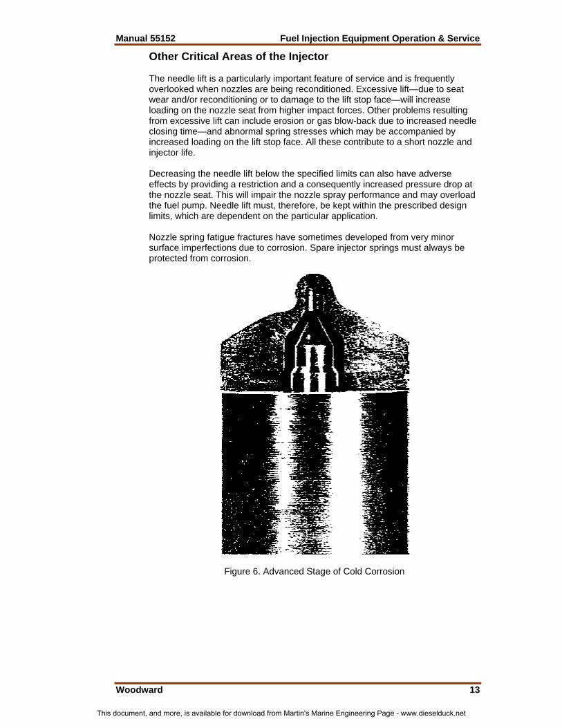
Figure 5 shows a conventional nozzle at an early stage of ‘cold corrosion’. This occurs when nozzles are over-cooled resulting from incorrect injector specification or engine operating temperatures. A combination of vapor from the exhaust gases, carbon deposits, and sulfur in the fuel results in sulfuric acid attack on the nozzle. The equipment will deteriorate and become unfit for service (see Figure 6) unless operating temperatures are correctly adjusted. Follow the engine manufacturer’s recommendation for coolant flows type/additives etc.
This document, and more, is available for download from Martin's Marine Engineering Page - www.dieselduck.net
Manual 55152 Fuel Injection Equipment Operation & Service
Woodward 13
Other Critical Areas of the Injector The needle lift is a particularly important feature of service and is frequently overlooked when nozzles are being reconditioned. Excessive lift—due to seat wear and/or reconditioning or to damage to the lift stop face—will increase loading on the nozzle seat from higher impact forces. Other problems resulting from excessive lift can include erosion or gas blow-back due to increased needle closing time—and abnormal spring stresses which may be accompanied by increased loading on the lift stop face. All these contribute to a short nozzle and injector life. Decreasing the needle lift below the specified limits can also have adverse effects by providing a restriction and a consequently increased pressure drop at the nozzle seat. This will impair the nozzle spray performance and may overload the fuel pump. Needle lift must, therefore, be kept within the prescribed design limits, which are dependent on the particular application. Nozzle spring fatigue fractures have sometimes developed from very minor surface imperfections due to corrosion. Spare injector springs must always be protected from corrosion.
Figure 6. Advanced Stage of Cold Corrosion
This document, and more, is available for download from Martin's Marine Engineering Page - www.dieselduck.net

Fuel Injection Equipment Operation & Service Manual 55152
14 Woodward
Servicing Methods The amount of fuel injection equipment servicing work varies from installation to installation with the number of engines and their running hours. The end user has three alternative methods of dealing with fuel injection equipment servicing: • Return to the Manufacturer’s Customer Service Department. • Return to the Manufacturer’s Agents or Distributors. • Use own servicing facilities. As the first two methods involve holding a float of equipment to keep the engine operating smoothly during servicing periods, some users prefer to handle simple routine work, using the manufacturer or agent for the major servicing jobs. Some larger users provide their own nozzle reconditioning service by using proprietary nozzle reconditioning equipment and staff trained by the various instructional courses offered by the manufacturer. Training courses are provided by Woodward for Agents, Distributors, and users of Woodward equipment. In these courses, personnel are instructed in the recommended methods and the use of the correct tools and equipment for the servicing, maintenance, repair, and testing of Woodward products. Such information and training is also made available to engine manufacturers and their customers as may be required.
6. Injector Removal and Examination General When the clamp or strongback is removed, the injector normally remains tight in the cylinder head. It is bad practice to lever the inlet connector (feed pipe) or injector body from side to side in order to break the carbon seal and then to lever the injector from the bore in the cylinder head. Use the proprietary tool recommended by the engine manufacturer. If none is available, a length of threaded rod welded to a spare injector cap nut can be used, in conjunction with a simple bridge piece or slide hammer, to withdraw the injector from the bore. Damaged Inlet Pipe Threads, Nozzle Tips, etc. Injector damage frequently occurs between the engine and the workshop. For smaller injectors, it is worthwhile to make up an ‘engine set’ carrier stand or box. For the larger sizes, some form of wheeled cart (trolley) or rack will be helpful. Protective caps should always be used for injection equipment in transit. Injector Bore Cleaning Tools When an injector is removed from the cylinder head, some loose carbon will fall to the bottom of the cylinder head injector bore. Use the tools recommended by the engine manufacturer or a profiled spade tool to remove any hard carbon, and a similarly shaped felt cleaner may be used to wipe the bore before the injector is refitted. A check should be made to ensure that extra sealing washers are not left in the bottom of the injector bore in the cylinder head. Only one new sealing washer should be fitted.
This document, and more, is available for download from Martin's Marine Engineering Page - www.dieselduck.net

Manual 55152 Fuel Injection Equipment Operation & Service
Woodward 15
Nozzle Checking Procedure It has become universal practice to judge injector condition by the ‘chatter’ or audible buzz produced when fuel is being pumped through it from the hand test unit. When the injector is on the engine, this state of instability or chatter will only occur under starting or possibly idling conditions. At normal operation speeds and loads, the nozzle lifts to its stop at the beginning and returns to its seat at the end of the injection period. Nozzle ‘chatter’ is, therefore, of less importance than is popularly believed—it merely serves to indicate that the nozzle needle is free. The quality and ‘tightness’ of the needle seat are of greater importance. Spray Check When the injector has been connected to the hand test unit, the gauge cock should be closed and the operating handle pumped briskly until all the air has been expelled from the pipe and injector. The quality of spray should be observed and any blocked holes listed. There should be no ragged edges or solid centers within the spray. Droplets and individual sprays should be equal in length, and features should be uniform. With the gauge cock open, the nozzle opening pressure should be checked in the condition as removed from the engine, and the figures listed. Seat Leakage Check The hand test unit should be operated through the full pump stroke after setting the nozzle opening pressure. The end face and tip of the nozzle must then be dried off. After slowly raising the pressure to within 10 bar (150 psi) of the nozzle operating pressure, the pressure should be maintained steady for 10 seconds before releasing the handle. The tip of the nozzle should still be dry with no droplet formation. Nozzles having large spray holes may be slightly wet, but the oil should not appear as significant droplets. Back Leakage Test Providing the nozzle needle seating is effective, the only remaining path is the clearance between needle and nozzle body, and the rate of leakage will be a function of the annular clearance between needle and nozzle bore. The time taken for the pressure to fall through a given range will thus indicate the needle clearance. Refer to the engine manufacturer’s instructions or to Woodward (Customer Services Department) for specific nozzle opening pressure and injector back-leak test data. Allowance must be made for variation in oil temperature using available temperature compensation charts. The manufacturers’ instructions must be closely followed. Clearly, it is of paramount importance that any leakage in the test equipment be rectified to ensure that nozzle back-leak times are not influenced by these shortcomings (for example, a low ‘back-leak’ time can result if the nozzle holder sealing faces are ineffective or leakage occurs at the injector vent screw). The test equipment should therefore be periodically checked for leaks and maintained in good repair at all times.
This document, and more, is available for download from Martin's Marine Engineering Page - www.dieselduck.net

Fuel Injection Equipment Operation & Service Manual 55152
16 Woodward
After prolonged periods of service on the engine, the back-leak times can be appreciably longer than usual. This is because the clearance between needle and nozzle has been reduced by the build-up of lacquer on the surfaces. Special de-lacquering solutions can be used to clean the surfaces and restore the nozzle during subsequent stripping operations, but special care must be taken to oil the precision surfaces during storage to prevent corrosion. The injector test machine should incorporate a lighted spray chamber to enable the number and targeting of sprays to be counted/checked. Failing this, nozzle spray hole condition can be checked by placing a sheet of cardboard or blotting paper just below the nozzle tip and depressing the hand pump handle sharply to give one crisp injection. The symmetry or otherwise of the ‘tear-drop’ stains on the paper will immediately reveal any blocked or partially blocked spray holes. Examination of Nozzle Holder Assemblies Prior to dismantling the injector, tips should be soaked in carbon-displacing fluid for several hours. It is essential to slacken the spring adjusting screw and release the tension before removing the nozzle nut. This is particularly important when dealing with doweled nozzles and holders, as the angular load on the dowel can raise a burr on the edge of the dowel hole when the nozzle face separates from the holder face while the nut is unscrewed. It is good practice to drift the nozzle through the nozzle nut as the nut is progressively slackened to prevent shearing the dowels of nozzle holders. Rectification is usually a matter of replacing damaged or worn components. Damage to the high-pressure face of the holder, if only slight, can be rectified by lapping with a very fine-grade lapping paste and a small lapping plate. Large and relatively heavy holder bodies can present difficulties in holding square and steady. It is therefore preferable to clamp the holder rigid and move the relatively light lapping plate on the injector body with a firm pressure. Ideally purpose-built lapping machines should be used. Severely indented or chipped thrust faces require replacement of the holder body. Injector springs should be checked at each service interval for squareness of the ends by standing them on a flat plate beside a try-square. Any bowing will be indicated by rubbing marks on one side of the coils. Evidence of pitting or corrosion on the wire surface requires the spring to be replaced. Any abnormal amount of metal dust or swarf in the injector feed pipe or edge filter indicates possible damage or a fault in the fuel feed system, and this should be checked, particularly the filtration equipment. Hard carbon inside the nozzle nut must be removed, as this can prevent the nozzle centralizing itself on the holder or even cause nozzle distortion when tightening the nut. The nozzle nut tightening torque must conform to manufacturers’ recommendations. Transfer blocks should be checked for fuel tracking across the high-pressure faces and indentation of the nozzle needle stop face into the block. All such witnesses should be removed by grinding/lapping, maintaining limits specified by Woodward Diesel Systems.
This document, and more, is available for download from Martin's Marine Engineering Page - www.dieselduck.net

Manual 55152 Fuel Injection Equipment Operation & Service
Woodward 17
Care of Water-cooled Injectors Water-cooled injectors are widely used on heavy-fuel engines, and the following special precautions should be taken to ensure their satisfactory operation: 1. The coolant passages of each injector should be blown out with a
compressed air line immediately upon removal from the engine. 2. The coolant circuit should be clean and unobstructed. Any dirt or pipe scale
from the coolant system must be flushed out to ensure that coolant flow is unrestricted.
3. It is advisable after re-assembly to blank off one end of the coolant circuit
and pressurize with compressed air. Subsequent immersion in the test tank will reveal any leakage across the sealing faces indicated by bubbles.
4. The complete coolant circuit can be further checked after installing the
injectors by running the circulating pump until the circuit is at the recommended pressure.
5. Leakage of fuel into the coolant circuit results in an oily scum on the top
surface of the coolant tank, and remedial action should be implemented to prevent further contamination.
6. If an engine normally equipped with cooled injectors is required to operate
on distillate fuel for prolonged periods, cold corrosion of the nozzle can occur due to overcooling. The nozzle coolant circuit should be disconnected if the operating conditions are of a temporary nature, but nozzles without a coolant passage and associated parts should be fitted to the injectors if these conditions are likely to last for several weeks or months.
7. The coolant temperature should reach the normal value (approximately
equal to the jacket water outlet temperature) quickly after starting. This value should be maintained regardless of engine load or fuel preheat temperature.
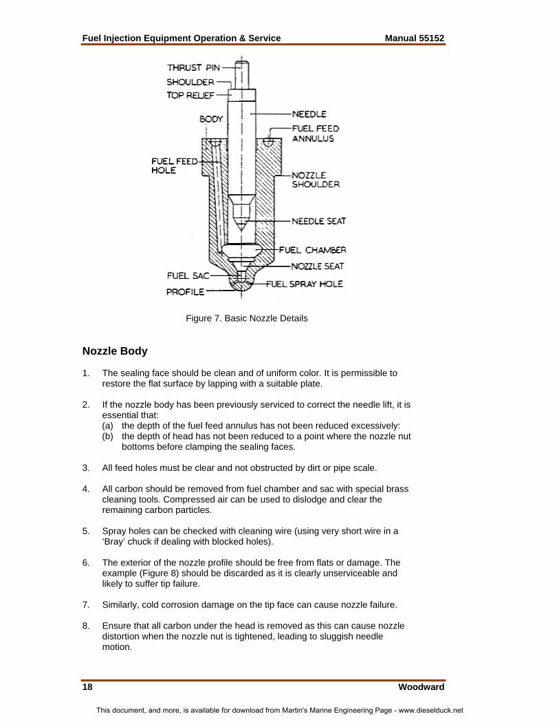
Examination of Nozzles Nozzle assemblies should be rinsed in ‘injector test oil’ or fuel oil, after removing all traces of external carbon. Paraffin must not be used. The nozzle can then be dismantled and examined. (See Figure 7.) 'T' size nozzle should be renewed at the agreed service intervals—it is uneconomic to refurbish these.
This document, and more, is available for download from Martin's Marine Engineering Page - www.dieselduck.net
Fuel Injection Equipment Operation & Service Manual 55152
18 Woodward
Figure 7. Basic Nozzle Details Nozzle Body 1. The sealing face should be clean and of uniform color. It is permissible to
restore the flat surface by lapping with a suitable plate. 2. If the nozzle body has been previously serviced to correct the needle lift, it is
essential that: (a) the depth of the fuel feed annulus has not been reduced excessively: (b) the depth of head has not been reduced to a point where the nozzle nut
bottoms before clamping the sealing faces. 3. All feed holes must be clear and not obstructed by dirt or pipe scale. 4. All carbon should be removed from fuel chamber and sac with special brass
cleaning tools. Compressed air can be used to dislodge and clear the remaining carbon particles.
5. Spray holes can be checked with cleaning wire (using very short wire in a
‘Bray’ chuck if dealing with blocked holes). 6. The exterior of the nozzle profile should be free from flats or damage. The
example (Figure 8) should be discarded as it is clearly unserviceable and likely to suffer tip failure.
7. Similarly, cold corrosion damage on the tip face can cause nozzle failure. 8. Ensure that all carbon under the head is removed as this can cause nozzle
distortion when the nozzle nut is tightened, leading to sluggish needle motion.
This document, and more, is available for download from Martin's Marine Engineering Page - www.dieselduck.net

Manual 55152 Fuel Injection Equipment Operation & Service
Woodward 19
9. After washing the nozzle, the condition of the seat should be checked with a probe light or microscope. The seating line must be narrow and not pitted. The earlier performance tests will have given an indication if the seat is excessively damaged.
10. All observations should be recorded.
Figure 8. Nozzle Damaged by Abuse Nozzle Needle 1. Any chipping or damage to the thrust pin usually renders the nozzle
assembly unfit for further service. 2. Feather edges on the thrust shoulder (caused by excessive impact on the
nozzle holder face) can, in extreme cases, cause jamming of needle and should therefore be trimmed off with a suitable stone.
3. Entrained dirt can be identified by small, clearly defined rectangular patches
of polish marks on the needle surface. The length of the dirt patches usually equals the needle lift.
4. Blackening or seizure of the needle is a clear indication of gas blow-back
due to a broken spring, low nozzle opening pressure, incorrect timing (causing overheating), or excessive needle lift.
5. All nozzles on a given engine should conform to specification. An incorrect
nozzle can result in discrepancies in needle opening and closing pressures, spray patterns, etc, with adjacent injectors.
6. A satisfactory nozzle will have a clean bright seating line at the top of the
seating cone. The extreme needle tip may be black, but the parallel portion above the seat should be clean and bright.
This document, and more, is available for download from Martin's Marine Engineering Page - www.dieselduck.net

Fuel Injection Equipment Operation & Service Manual 55152
20 Woodward
Nozzle and Needle Seat Reclamation Nozzles suffering severe mechanical damage or excessive back-leakage should be replaced. The correct performance of the remainder will depend on the following: • A really free needle and cleanliness of all parts; • Restoration of the correct angular difference between needle and body seat
in order to re-establish an effective seal at that point. • Correction of needle lift. The correct angle on the needle can only be restored with a precision grinder or specialist nozzle reconditioning machine. The body seat is restored by lapping the seat with a cast iron lap and very fine lapping paste. The lap itself wears with use, and the correct angle must be maintained by grinding on the needle-grinding machine. The machine must be re-set, if necessary, to maintain the correct angular difference between needle and seat. Seat and needle angles can vary between manufacturers and also with nozzle type. In the majority of cases, a 60° nominal seating angle is used with a differential clearance between needle and nozzle seat of the order of 0.75° (i.e. 45'). Refer to specific data as required. Nozzle performance will not be restored by grinding the needle seat and lapping the nozzle seat to identical angles, and the needle must not be heavily lapped into the nozzle seat. It is however permissible to touch or lightly lap the needle in the body sufficient to obtain a witness mark and confirm the position and width of the seating line. The needle lift should always be checked after the seat has been re-established. Needle Lift The maintenance of correct needle lift significantly influences nozzle life and combustion. Excessive lift increases injector spring stresses and can result in impact damage to both the needle shoulder, nozzle holder and face, and nozzle seating. The higher lift also increases the time for the needle to seat at the end of injection, thus increasing the possibility of combustion gas ‘blow-back’ and the resulting adverse effects on nozzle performance. The simplest way to measure needle lift is illustrated in Figure 9. The dial gauge should be ‘zeroed’ at position A and the lift read off when the pointer has moved to position B. Indentation or chipping of the nozzle holder end face can also allow excess needle travel and should be rectified immediately.
This document, and more, is available for download from Martin's Marine Engineering Page - www.dieselduck.net

Manual 55152 Fuel Injection Equipment Operation & Service
Woodward 21
7. Product Identification Pump Assembly Coding
Nozzle Holder Coding
Nozzle Assembly Coding (Hole Type)
This document, and more, is available for download from Martin's Marine Engineering Page - www.dieselduck.net

Fuel Injection Equipment Operation & Service Manual 55152
22 Woodward
8. Health and Safety For Recommendations on the Safe Handling of Woodward Fuel Injection Equipment, refer to service bulletin number 01539 (old number 308). Pumps 1. Ensure that the correct procedures and torque values as specified in the
appropriate workshop manuals and service instructions are used when assembling a pump.
2. Pumps must be tested and adjusted in accordance with the instructions
given in Woodward service test specifications and/or workshop manuals, and must not be adjusted outside the limits or conditions specified by Woodward Diesel Systems.
3. Before running a pump, either on a test rig or on an engine, ensure that all
parts of the pump, the pump itself, and its drive arrangements are secured, tight, and adequately guarded. Make certain that all pipes and controls are correctly connected. Ensure that the pump is lubricated as specified by Woodward Diesel Systems prior to being run either on a test rig or on the engine.
4. When a pump is running on an engine or test rig, no parts, pipes, or controls
are to be disconnected except as directed by Woodward Diesel Systems or the engine manufacturer in their service information.
5. Do not attempt to make any timing, fuel, governor, or other adjustment to a
pump while it is running, whether on an engine or test rig, except as directed by Woodward Diesel Systems or the engine manufacturer in their service information.
6. Do not run pumps at speeds in excess of those specified by Woodward
Diesel Systems. 7. Bear in mind that a fuel injection pump generates powerful mechanical
forces and high oil pressures, therefore ensure that all pump testing equipment, including all test bench drive arrangements and securing devices, are regularly inspected and maintained in good order. Renew all worn or damaged parts.
Fuel Injection Equipment Servicing Room Since fuel injection equipment is manufactured to very fine limits and can easily be damaged by dirt, it is essential to provide a separate and clean section of the workshop or ideally, a totally separate room, in which to handle it. The requirements of such a room are: 1. An enclosed space. 2. Work benches bolted rigidly to the floor and surfaced with aluminum, plastic
sheet, or suitable alternative. All vises to have the hardened jaws ground flat to avoid defacing equipment. Injector and pump-holding fixtures bolted to the front of benches will reduce servicing time.
This document, and more, is available for download from Martin's Marine Engineering Page - www.dieselduck.net
Manual 55152 Fuel Injection Equipment Operation & Service
Woodward 23
3. Adequate overhead lighting with points for specialized injector viewing or magnifying lights.
4. ‘Dirty’ washing-off tank, preferably outside the room, with smaller cleaning
trays and ‘clean’ washing tank inside. 5. Compressed air points for gun and air test connections. 6. Separate injector test bench with injector test unit and rigid support fixturing
for the various types or sizes of injector handled. Note that the nozzle tip should be visible and not masked by the collecting tray. Ideally, the nozzle tip should be located inside a transparent collecting vessel.
7. Storage racks and bins, also shallow trays for disassembled components. 8. Racks to hold complete sets of injectors 'awaiting attention’, or ‘rectified’ to
leave working bench space clear. 9. Pump support and disassembly brackets with tappet depressing tool, air test
tank, static timing tank, and connections. 10. Pedestal desk for records, etc, well clear of benches. 11. If it is intended to recondition nozzles on the premises, a specialized nozzle
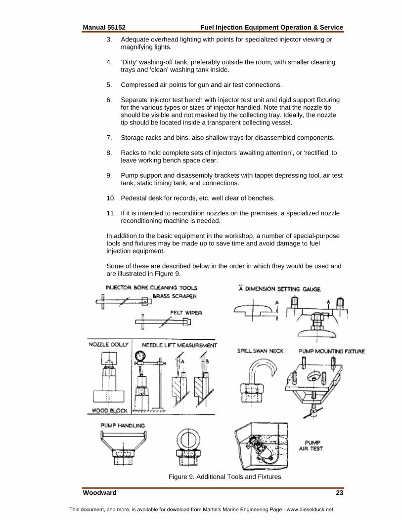
reconditioning machine is needed. In addition to the basic equipment in the workshop, a number of special-purpose tools and fixtures may be made up to save time and avoid damage to fuel injection equipment. Some of these are described below in the order in which they would be used and are illustrated in Figure 9.
Figure 9. Additional Tools and Fixtures
This document, and more, is available for download from Martin's Marine Engineering Page - www.dieselduck.net

We appreciate your comments about the content of our publications.
Send comments to: [email protected]
Please reference publication 55152.
PO Box 1519, Fort Collins CO 80522-1519, USA 1000 East Drake Road, Fort Collins CO 80525, USA Phone +1 (970) 482-5811 • Fax +1 (970) 498-3058
Email and Website—www.woodward.com
Woodward has company-owned plants, subsidiaries, and branches, as well as authorized distributors and other authorized service and sales facilities throughout the world.
Complete address / phone / fax / email information for all locations is available on our website.
2009/2/Fort Collins
This document, and more, is available for download from Martin's Marine Engineering Page - www.dieselduck.net