fuel injection (fuel systems) (h4so)
TRANSCRIPT
FUEL INJECTION (FUEL SYSTEMS)
(H4SO)
FUEL INJECTION (FUEL SYSTEM)GENERAL
FU(H4SO)-2
1. GeneralThe Multipoint Fuel Injection (MFI) system supplies optimum air-fuel mixture under every engine
operating condition through the use of the latest electronic control technology.
This system pressurizes the fuel to a constant pressure and injects it into each intake air port in thecylinder head. The injection quantity of fuel is controlled by an intermittent injection system wherean electro-magnetic injection valve or injector opens for a short period that is precisely controlleddepending on the quantity of air appropriate for each condition of operation. In actual control, anoptimum fuel injection quantity is achieved by varying the duration of an electric pulse applied to theinjector. This way of control enables simple, yet highly precise metering of the fuel.
The engine control module (ECM) that controls the fuel injection system corrects the fuel injectionamount depending on the vehicle speed, throttle opening, coolant temperature and other vehicle-operation-related information. The ECM receives the information in the form of electric signals fromthe corresponding sensors and switches.
The MFI system also has the following features:
Reduced exhaust emissions
Improves fuel efficiency
Increased engine output
Quick response to accelerator and brake pedal operation
Superior start ability and warm-up performance in cold weather due to corrective controls madeaccording to coolant and intake air temperatures
FUEL INJECTION (FUEL SYSTEM)AIR LINE
FU(H4SO)-3
2. Air LineA: GENERALThe air filtered by the air cleaner enters the throttle body where it is regulated in the volume by thethrottle valve and then enters the intake manifold. It is then distributed to each cylinder where theair is mixed with fuel injected by the injector.
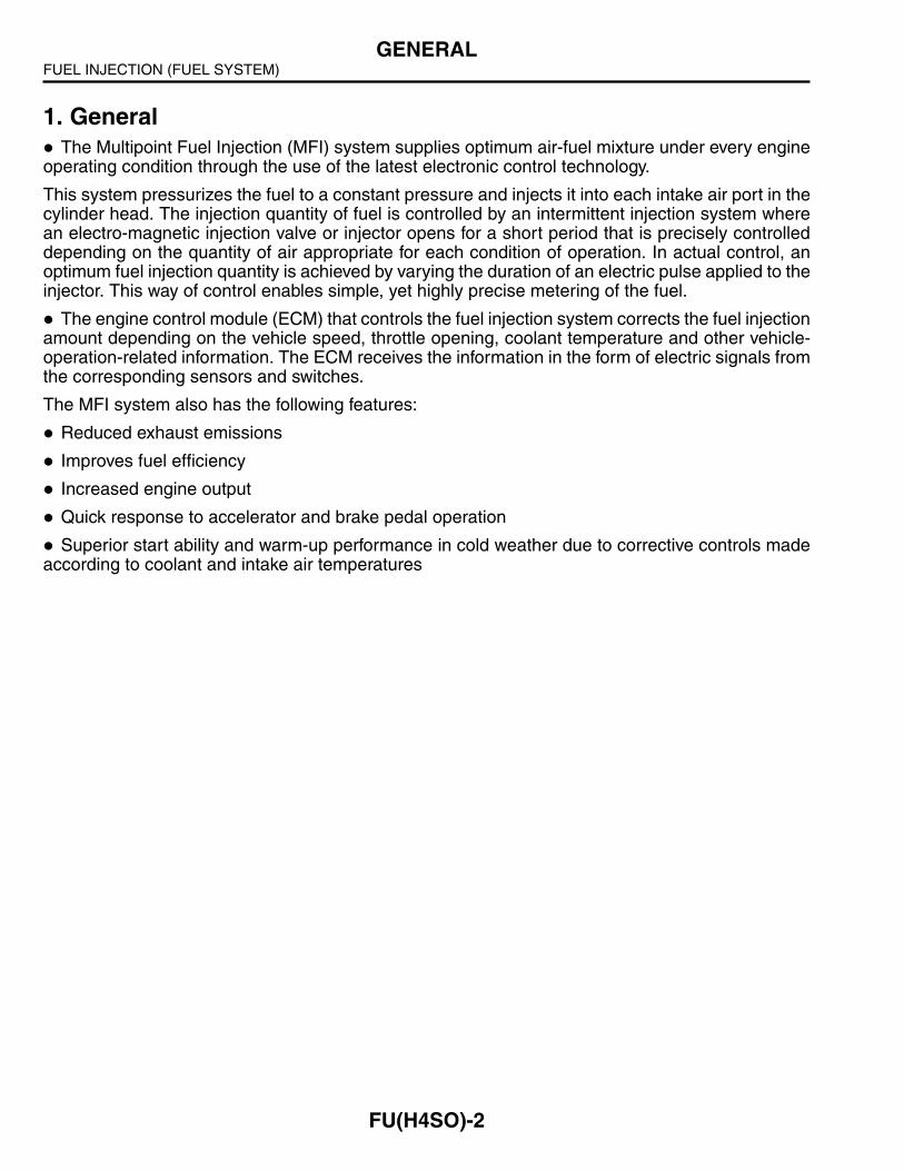
B: MANIFOLD ABSOLUTE PRESSURE SENSORThe manifold absolute pressure sensor is attached to the top of the throttle body, and continuouslysends to the engine control module (ECM) voltage signals that are proportional to intake manifoldabsolute pressures. The ECM controls the fuel injection and ignition timing based on the intakemanifold absolute pressure signals in addition to other signals from many sensors and other controlmodules.
(1) Connector (A) Output voltage
(2) Terminal (B) Absolute pressure
(3) O-ring
(B)
(A)
(2)
(3)
(1)
FU-02010
FUEL INJECTION (FUEL SYSTEM)AIR LINE
FU(H4SO)-4
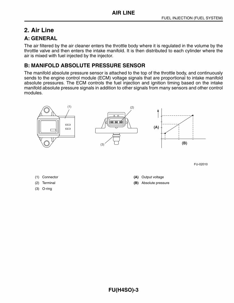
C: ELECTRONIC CONTROL THROTTLE SYSTEMThe electronic control throttle system consists of an accelerator pedal position sensor mounted
on the accelerator pedal, a throttle position sensor and a throttle motor mounted on the throttle body,and the ECM, which controls these devices.
The movement of the accelerator pedal is converted into electrical signals by the accelerator ped-al position sensor and sent to the ECM. Based on these signals the ECM controls the throttle motorto open and close the throttle valve.
Idling control is now performed by the electronic control throttle system in place of the idle air con-trol solenoid valve.
(1) Throttle position sensor (4) Electronic control throttle relay
(2) Accelerator pedal position sensor (5) ECM
(3) Electronic control throttle assembly
(5)(4)
(3)(1)
(2)
FU-01230
FUEL INJECTION (FUEL SYSTEM)AIR LINE
FU(H4SO)-5
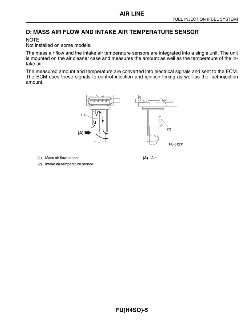
D: MASS AIR FLOW AND INTAKE AIR TEMPERATURE SENSORNOTE: Not installed on some models.
The mass air flow and the intake air temperature sensors are integrated into a single unit. The unitis mounted on the air cleaner case and measures the amount as well as the temperature of the in-take air.
The measured amount and temperature are converted into electrical signals and sent to the ECM.The ECM uses these signals to control injection and ignition timing as well as the fuel injectionamount.
(1) Mass air flow sensor (A) Air
(2) Intake air temperature sensor
(A)(2)
(1)
FU-01231

FUEL INJECTION (FUEL SYSTEM)AIR LINE
FU(H4SO)-6
E: TUMBLE GENERATOR VALVENOTE: This is not installed on some models.
A tumble generator valve is provided on the intake manifold of each engine bank. The right banktumble generator valve has butterfly valves for the #1 and #3 cylinders and the left bank tumble gen-erator valve has those for the #2 and #4 cylinders. The two butterfly valves in each tumble generatorvalve are fitted on a single shaft that is driven by an actuator.
The tumble generator valves are controlled by the ECM according to the coolant temperature andthe time elapsed after start of the engine. When the engine is started, the butterfly valves are movedto the closing ends.In this state, the intake air flows at very high speeds passing through narrowedpassages in the directions determined by the individual intake air ports in the cylinder head. Thiscreates tumbling air motions in the cylinders, which enables lean mixtures to be ignited and thusharmful exhaust emissions to be reduced during engine start. The tumble generator valves are fullyopen when the engine is operating at an ordinary driving speed, allowing intake air to flow withoutbeing changed in direction and velocity.
(A) Activated
(B) Not activated
(1) Actuator (6) Tumble generating air passage
(2) Tumble generator valve position sensor (7) Main intake air passage
(3) Tumble generator housing (8) Piston
(4) Intake manifold (9) Injector
(5) Tumble generator valve (10) Cylinder head
(1)
(3)
(3) (3)
(4) (4)
(6)(6)
(9) (9)
(10)(10)
(5)
(7) (7)
(5)
(8)(8)
(2)
(A) (B)
FU-01316
FUEL INJECTION (FUEL SYSTEM)FUEL SYSTEM
FU(H4SO)-7
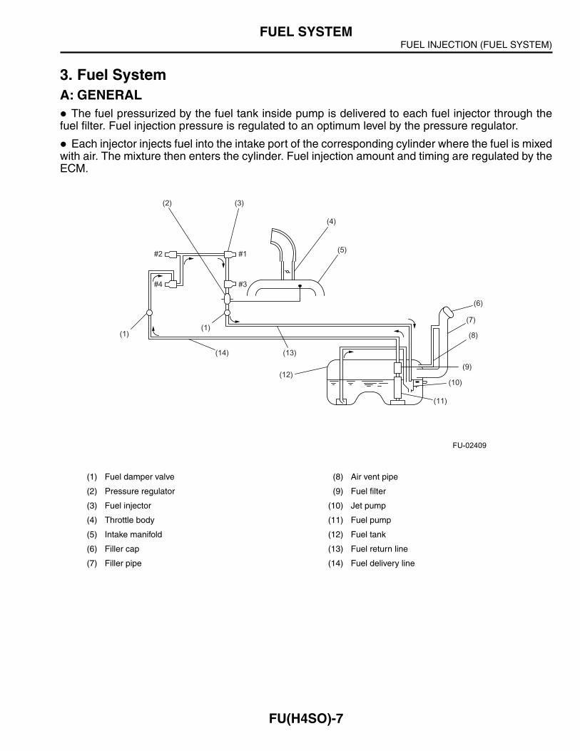
3. Fuel SystemA: GENERAL
The fuel pressurized by the fuel tank inside pump is delivered to each fuel injector through thefuel filter. Fuel injection pressure is regulated to an optimum level by the pressure regulator.
Each injector injects fuel into the intake port of the corresponding cylinder where the fuel is mixedwith air. The mixture then enters the cylinder. Fuel injection amount and timing are regulated by theECM.
(1) Fuel damper valve (8) Air vent pipe
(2) Pressure regulator (9) Fuel filter
(3) Fuel injector (10) Jet pump
(4) Throttle body (11) Fuel pump
(5) Intake manifold (12) Fuel tank
(6) Filler cap (13) Fuel return line
(7) Filler pipe (14) Fuel delivery line
(4)
(5)
(6)
(7)
(8)
(9)
(10)
(11)
(12)
(13)(14)
(1)(1)
(3)(2)
#2 #1
#4 #3
FU-02409
FUEL INJECTION (FUEL SYSTEM)FUEL SYSTEM
FU(H4SO)-8
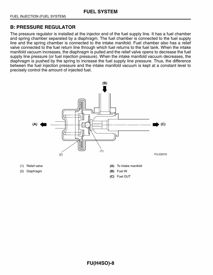
B: PRESSURE REGULATORThe pressure regulator is installed at the injector end of the fuel supply line. It has a fuel chamberand spring chamber separated by a diaphragm. The fuel chamber is connected to the fuel supplyline and the spring chamber is connected to the intake manifold. Fuel chamber also has a reliefvalve connected to the fuel return line through which fuel returns to the fuel tank. When the intakemanifold vacuum increases, the diaphragm is pulled and the relief valve opens to decrease the fuelsupply line pressure (or fuel injection pressure). When the intake manifold vacuum decreases, thediaphragm is pushed by the spring to increase the fuel supply line pressure. Thus, the differencebetween the fuel injection pressure and the intake manifold vacuum is kept at a constant level toprecisely control the amount of injected fuel.
(1) Relief valve (A) To intake manifold
(2) Diaphragm (B) Fuel IN
(C) Fuel OUT
(B)
(C)(A)
(1)
(2) FU-02410
FUEL INJECTION (FUEL SYSTEM)FUEL SYSTEM
FU(H4SO)-9
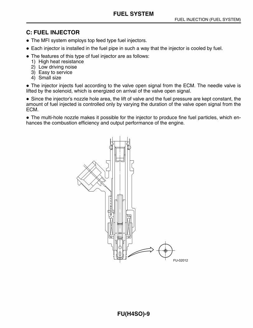
C: FUEL INJECTORThe MFI system employs top feed type fuel injectors.
Each injector is installed in the fuel pipe in such a way that the injector is cooled by fuel.
The features of this type of fuel injector are as follows:1) High heat resistance2) Low driving noise3) Easy to service4) Small size
The injector injects fuel according to the valve open signal from the ECM. The needle valve islifted by the solenoid, which is energized on arrival of the valve open signal.
Since the injector’s nozzle hole area, the lift of valve and the fuel pressure are kept constant, theamount of fuel injected is controlled only by varying the duration of the valve open signal from theECM.
The multi-hole nozzle makes it possible for the injector to produce fine fuel particles, which en-hances the combustion efficiency and output performance of the engine.
FU-02012
FUEL INJECTION (FUEL SYSTEM)FUEL SYSTEM
FU(H4SO)-10
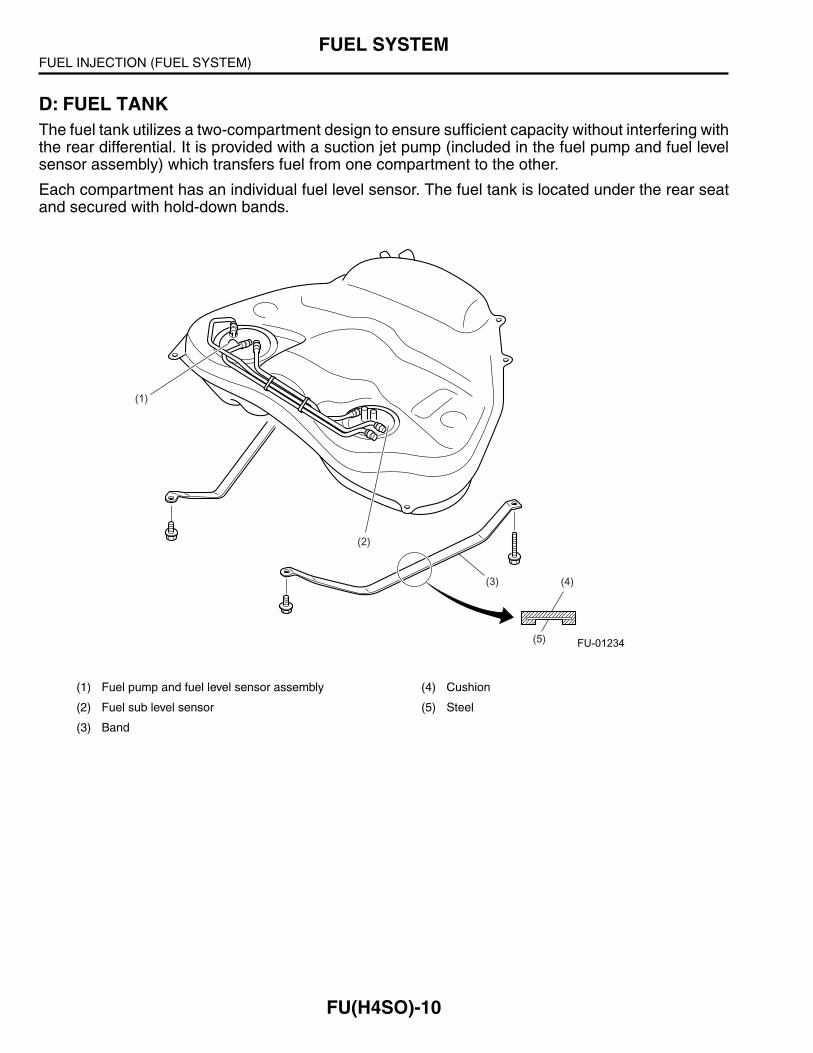
D: FUEL TANKThe fuel tank utilizes a two-compartment design to ensure sufficient capacity without interfering withthe rear differential. It is provided with a suction jet pump (included in the fuel pump and fuel levelsensor assembly) which transfers fuel from one compartment to the other.
Each compartment has an individual fuel level sensor. The fuel tank is located under the rear seatand secured with hold-down bands.
(1) Fuel pump and fuel level sensor assembly (4) Cushion
(2) Fuel sub level sensor (5) Steel
(3) Band
(3)
(1)
(2)
(4)
(5) FU-01234
FUEL INJECTION (FUEL SYSTEM)FUEL SYSTEM
FU(H4SO)-11
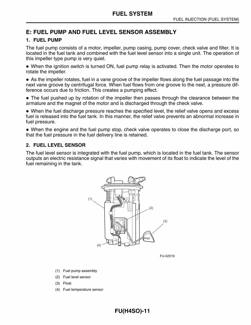
E: FUEL PUMP AND FUEL LEVEL SENSOR ASSEMBLY1. FUEL PUMP
The fuel pump consists of a motor, impeller, pump casing, pump cover, check valve and filter. It islocated in the fuel tank and combined with the fuel level sensor into a single unit. The operation ofthis impeller type pump is very quiet.
When the ignition switch is turned ON, fuel pump relay is activated. Then the motor operates torotate the impeller.
As the impeller rotates, fuel in a vane groove of the impeller flows along the fuel passage into thenext vane groove by centrifugal force. When fuel flows from one groove to the next, a pressure dif-ference occurs due to friction. This creates a pumping effect.
The fuel pushed up by rotation of the impeller then passes through the clearance between thearmature and the magnet of the motor and is discharged through the check valve.
When the fuel discharge pressure reaches the specified level, the relief valve opens and excessfuel is released into the fuel tank. In this manner, the relief valve prevents an abnormal increase infuel pressure.
When the engine and the fuel pump stop, check valve operates to close the discharge port, sothat the fuel pressure in the fuel delivery line is retained.
2. FUEL LEVEL SENSOR
The fuel level sensor is integrated with the fuel pump, which is located in the fuel tank. The sensoroutputs an electric resistance signal that varies with movement of its float to indicate the level of thefuel remaining in the tank.
(1) Fuel pump assembly
(2) Fuel level sensor
(3) Float
(4) Fuel temperature sensor
(2)
(1)
(4)
(3)
FU-02519

FUEL INJECTION (FUEL SYSTEM)FUEL SYSTEM
FU(H4SO)-12
3. JET PUMP
The jet pump utilizes the velocity of fuel returning from the engine to produce vacuum in it.
Using the pumping effect produced by the vacuum, the jet pump transfers fuel from the sub-com-partment and main compartment of the fuel tank to the fuel pump.
When the return line nozzle is clogged, the fuel sent back through the return line flows back intothe fuel tank via the relief valve.
4. FUEL FILTER
The fuel filter is integrated with the fuel pump assembly, which is located in the fuel tank.
(1) Relief valve (A) Return line
(2) Nozzle
(A)(A)
(1)
(2)
(A)
FU-00226
FUEL INJECTION (FUEL SYSTEM)FUEL SYSTEM
FU(H4SO)-13
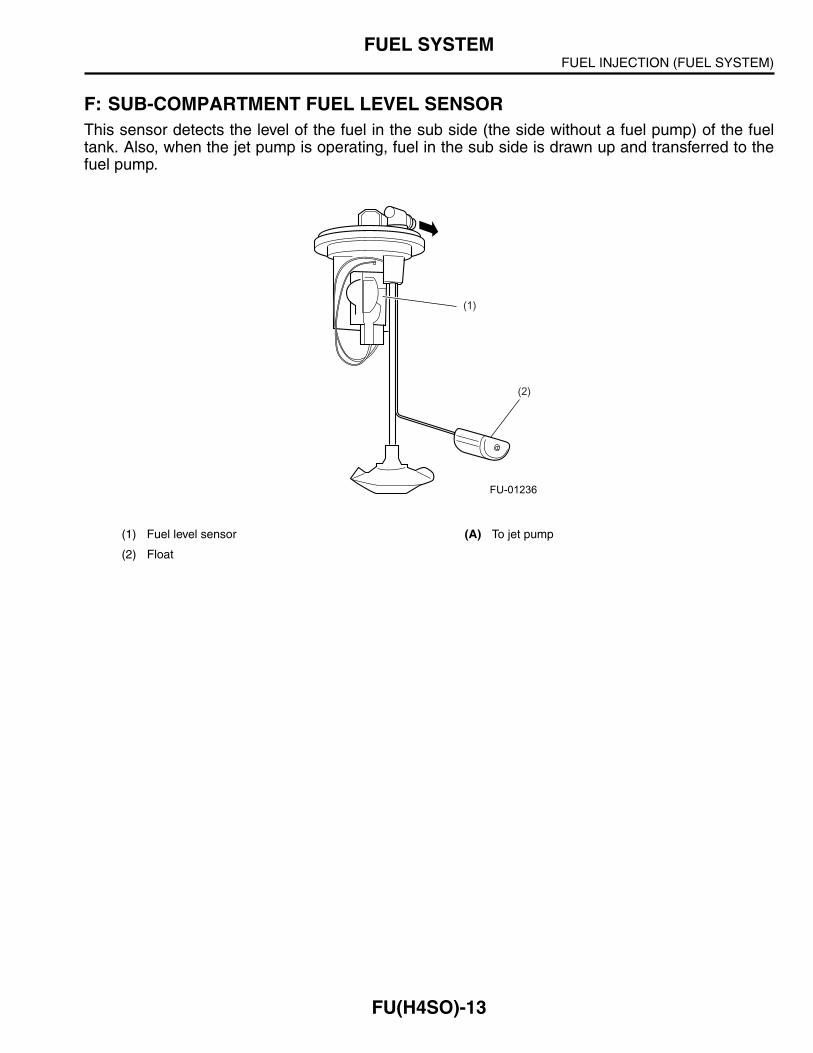
F: SUB-COMPARTMENT FUEL LEVEL SENSORThis sensor detects the level of the fuel in the sub side (the side without a fuel pump) of the fueltank. Also, when the jet pump is operating, fuel in the sub side is drawn up and transferred to thefuel pump.
(1) Fuel level sensor (A) To jet pump
(2) Float
(1)
(2)
FU-01236
FUEL INJECTION (FUEL SYSTEM)SENSORS AND SWITCHES
FU(H4SO)-14
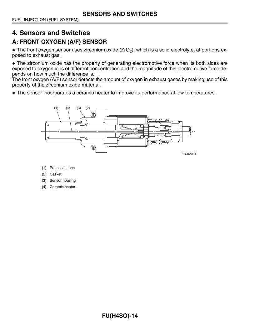
4. Sensors and SwitchesA: FRONT OXYGEN (A/F) SENSOR
The front oxygen sensor uses zirconium oxide (ZrO2), which is a solid electrolyte, at portions ex-posed to exhaust gas.
The zirconium oxide has the property of generating electromotive force when its both sides areexposed to oxygen ions of different concentration and the magnitude of this electromotive force de-pends on how much the difference is.The front oxygen (A/F) sensor detects the amount of oxygen in exhaust gases by making use of thisproperty of the zirconium oxide material.
The sensor incorporates a ceramic heater to improve its performance at low temperatures.
(1) Protection tube
(2) Gasket
(3) Sensor housing
(4) Ceramic heater
(2)(3)(4)(1)
FU-02014
FUEL INJECTION (FUEL SYSTEM)SENSORS AND SWITCHES
FU(H4SO)-15
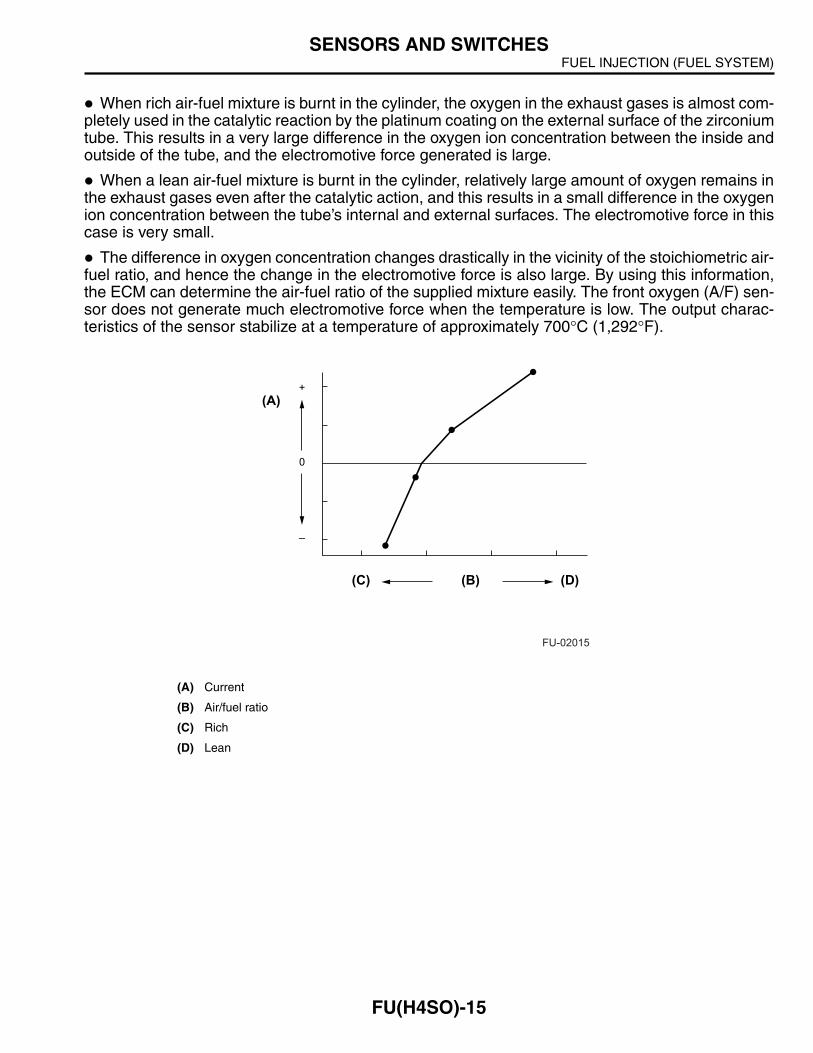
When rich air-fuel mixture is burnt in the cylinder, the oxygen in the exhaust gases is almost com-pletely used in the catalytic reaction by the platinum coating on the external surface of the zirconiumtube. This results in a very large difference in the oxygen ion concentration between the inside andoutside of the tube, and the electromotive force generated is large.
When a lean air-fuel mixture is burnt in the cylinder, relatively large amount of oxygen remains inthe exhaust gases even after the catalytic action, and this results in a small difference in the oxygenion concentration between the tube’s internal and external surfaces. The electromotive force in thiscase is very small.
The difference in oxygen concentration changes drastically in the vicinity of the stoichiometric air-fuel ratio, and hence the change in the electromotive force is also large. By using this information,the ECM can determine the air-fuel ratio of the supplied mixture easily. The front oxygen (A/F) sen-sor does not generate much electromotive force when the temperature is low. The output charac-teristics of the sensor stabilize at a temperature of approximately 700°C (1,292°F).
(A) Current
(B) Air/fuel ratio
(C) Rich
(D) Lean
(C)
(A)
0
+
–
(B) (D)
FU-02015
FUEL INJECTION (FUEL SYSTEM)SENSORS AND SWITCHES
FU(H4SO)-16
B: FRONT OXYGEN SENSOR AND REAR OXYGEN SENSORNOTE: The front oxygen sensor is not installed on some models.
The front oxygen sensor and rear oxygen sensor are used to sense oxygen concentration in theexhaust gas. If the air-fuel ratio is leaner than the stoichiometric ratio in the mixture (i.e., excessiveamount of air), the exhaust gas contains more oxygen. To the contrary, if the fuel ratio is richer thanthe stoichiometric ratio, the exhaust gas contains almost no oxygen.
Detecting the oxygen concentration in exhaust gas using the front oxygen sensor and rear oxygensensor makes it possible to determine whether the air-fuel ratio is leaner or richer than the stoichi-ometric ratio.
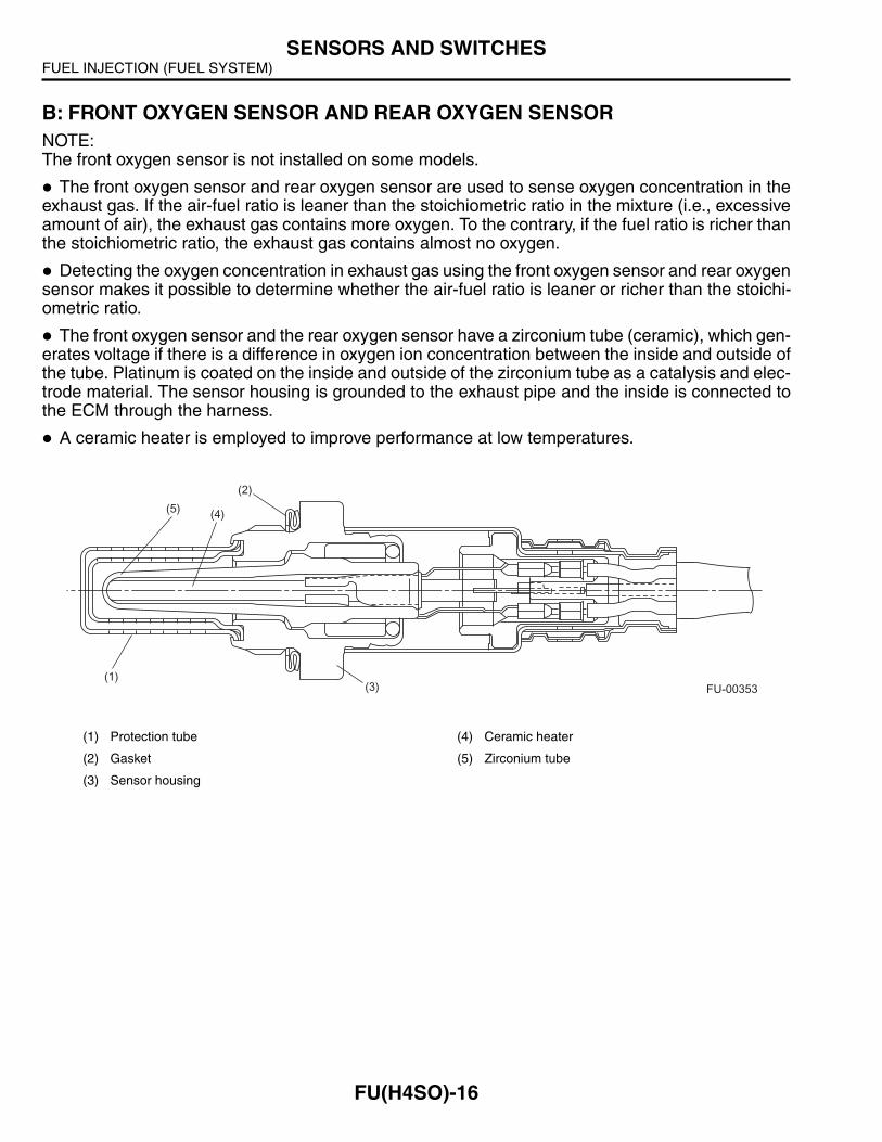
The front oxygen sensor and the rear oxygen sensor have a zirconium tube (ceramic), which gen-erates voltage if there is a difference in oxygen ion concentration between the inside and outside ofthe tube. Platinum is coated on the inside and outside of the zirconium tube as a catalysis and elec-trode material. The sensor housing is grounded to the exhaust pipe and the inside is connected tothe ECM through the harness.
A ceramic heater is employed to improve performance at low temperatures.
(1) Protection tube (4) Ceramic heater
(2) Gasket (5) Zirconium tube
(3) Sensor housing
(1)
(2)
(3)
(4)(5)
FU-00353
FUEL INJECTION (FUEL SYSTEM)SENSORS AND SWITCHES
FU(H4SO)-17
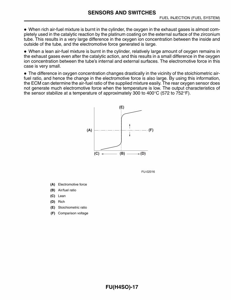
When rich air-fuel mixture is burnt in the cylinder, the oxygen in the exhaust gases is almost com-pletely used in the catalytic reaction by the platinum coating on the external surface of the zirconiumtube. This results in a very large difference in the oxygen ion concentration between the inside andoutside of the tube, and the electromotive force generated is large.
When a lean air-fuel mixture is burnt in the cylinder, relatively large amount of oxygen remains inthe exhaust gases even after the catalytic action, and this results in a small difference in the oxygenion concentration between the tube’s internal and external surfaces. The electromotive force in thiscase is very small.
The difference in oxygen concentration changes drastically in the vicinity of the stoichiometric air-fuel ratio, and hence the change in the electromotive force is also large. By using this information,the ECM can determine the air-fuel ratio of the supplied mixture easily. The rear oxygen sensor doesnot generate much electromotive force when the temperature is low. The output characteristics ofthe sensor stabilize at a temperature of approximately 300 to 400°C (572 to 752°F).
(A) Electromotive force
(B) Air/fuel ratio
(C) Lean
(D) Rich
(E) Stoichiometric ratio
(F) Comparison voltage
(E)
(F)
(C) (B) (D)
(A)
FU-02016

FUEL INJECTION (FUEL SYSTEM)SENSORS AND SWITCHES
FU(H4SO)-18
C: ENGINE COOLANT TEMPERATURE SENSORThe engine coolant temperature sensor is located on the engine coolant pipe. The sensor uses athermistor whose resistance changes inversely with temperature. Resistance signals as enginecoolant temperature information are transmitted to the ECM to make fuel injection, ignition timing,purge control solenoid valve and other controls.
(1) Connector (A) Resistance (kΩ)
(2) Thermistor element (B) Temperature °C (°F)
(B)
(A)
(2)
(1)
FU-02017
FUEL INJECTION (FUEL SYSTEM)SENSORS AND SWITCHES
FU(H4SO)-19
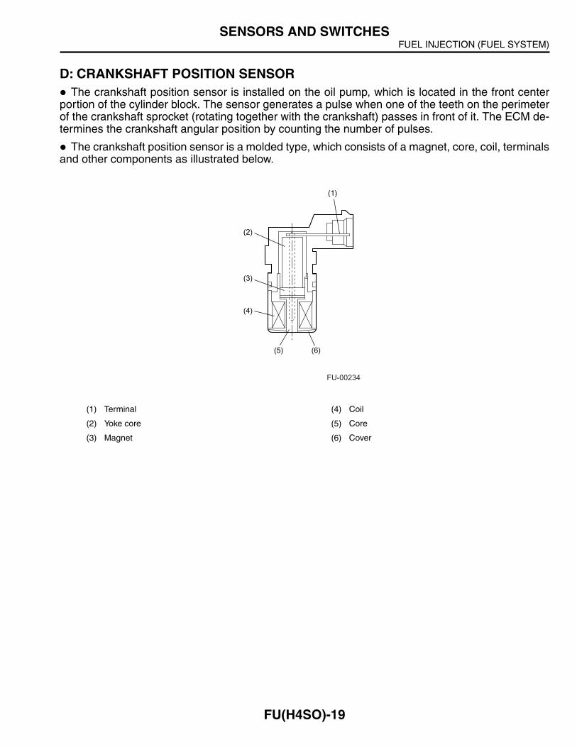
D: CRANKSHAFT POSITION SENSORThe crankshaft position sensor is installed on the oil pump, which is located in the front center
portion of the cylinder block. The sensor generates a pulse when one of the teeth on the perimeterof the crankshaft sprocket (rotating together with the crankshaft) passes in front of it. The ECM de-termines the crankshaft angular position by counting the number of pulses.
The crankshaft position sensor is a molded type, which consists of a magnet, core, coil, terminalsand other components as illustrated below.
(1) Terminal (4) Coil
(2) Yoke core (5) Core
(3) Magnet (6) Cover
(1)
(2)
(3)
(4)
(5) (6)
FU-00234
FUEL INJECTION (FUEL SYSTEM)SENSORS AND SWITCHES
FU(H4SO)-20
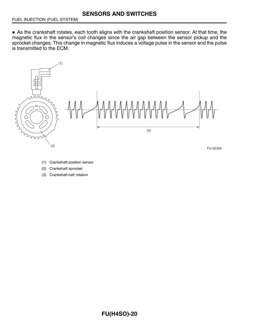
As the crankshaft rotates, each tooth aligns with the crankshaft position sensor. At that time, themagnetic flux in the sensor’s coil changes since the air gap between the sensor pickup and thesprocket changes. This change in magnetic flux induces a voltage pulse in the sensor and the pulseis transmitted to the ECM.
(1) Crankshaft position sensor
(2) Crankshaft sprocket
(3) Crankshaft half rotation
(1)
(2)
(3)
FU-00354
FUEL INJECTION (FUEL SYSTEM)SENSORS AND SWITCHES
FU(H4SO)-21
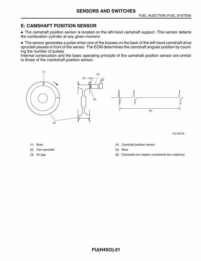
E: CAMSHAFT POSITION SENSORThe camshaft position sensor is located on the left-hand camshaft support. This sensor detects
the combustion cylinder at any given moment.
The sensor generates a pulse when one of the bosses on the back of the left-hand camshaft drivesprocket passes in front of the sensor. The ECM determines the camshaft angular position by count-ing the number of pulses.Internal construction and the basic operating principle of the camshaft position sensor are similarto those of the crankshaft position sensor.
(1) Boss (4) Camshaft position sensor
(2) Cam sprocket (5) Boss
(3) Air gap (6) Camshaft one rotation (crankshaft two rotations)
(1)
(3)
(4)
(5)
(2)
(6)
FU-02018
FUEL INJECTION (FUEL SYSTEM)SENSORS AND SWITCHES
FU(H4SO)-22
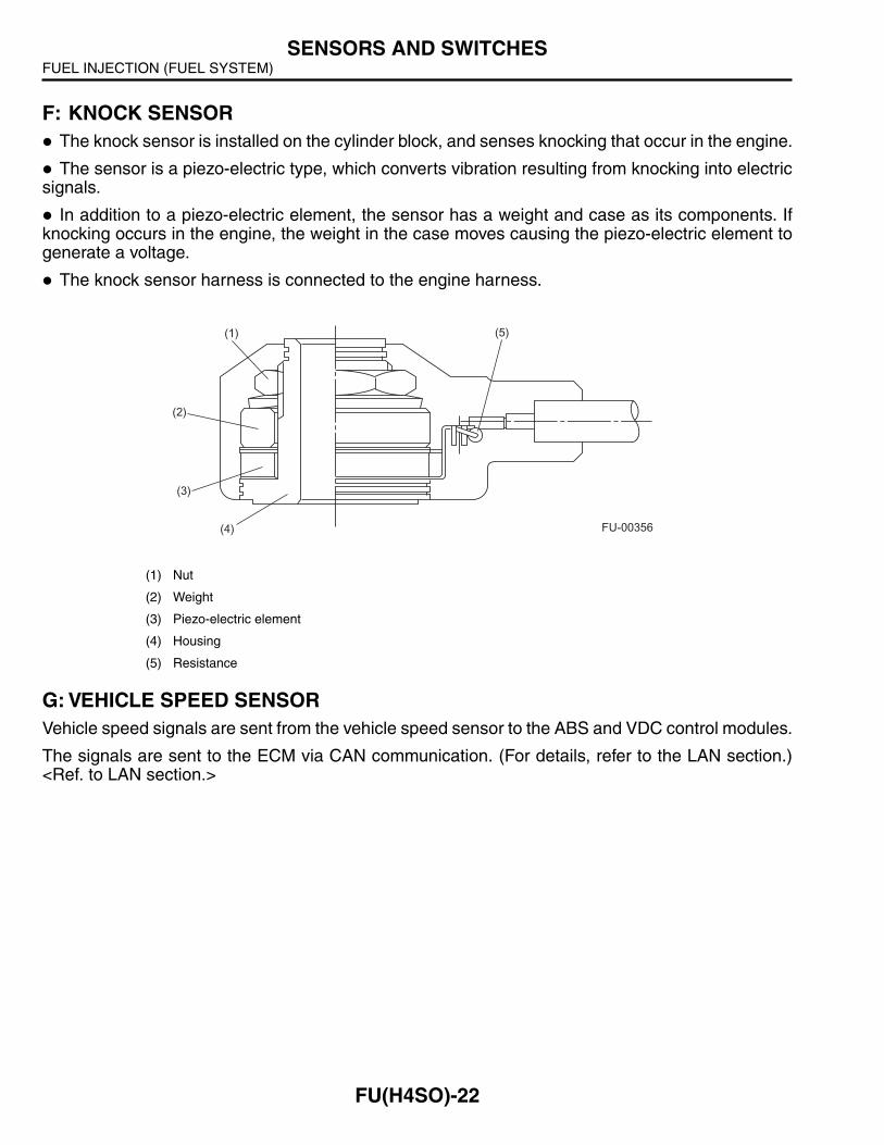
F: KNOCK SENSORThe knock sensor is installed on the cylinder block, and senses knocking that occur in the engine.
The sensor is a piezo-electric type, which converts vibration resulting from knocking into electricsignals.
In addition to a piezo-electric element, the sensor has a weight and case as its components. Ifknocking occurs in the engine, the weight in the case moves causing the piezo-electric element togenerate a voltage.
The knock sensor harness is connected to the engine harness.
G: VEHICLE SPEED SENSORVehicle speed signals are sent from the vehicle speed sensor to the ABS and VDC control modules.
The signals are sent to the ECM via CAN communication. (For details, refer to the LAN section.)<Ref. to LAN section.>
(1) Nut
(2) Weight
(3) Piezo-electric element
(4) Housing
(5) Resistance
(1)
(2)
(3)
(4)
(5)
FU-00356
FUEL INJECTION (FUEL SYSTEM)CONTROL SYSTEM
FU(H4SO)-23
5. Control SystemA: GENERALThe ECM receives signals from various sensors, switches, and other control modules. Using thesesignals, it determines the engine operating conditions and if necessary, emits signals to one or moresystems to control them for optimum operation.
Major control items of the ECM are as follows:
Fuel injection control
Ignition control
Idle air control
Fuel pump control
Canister purge control*1
Radiator fan control*2
On-board diagnosis function
*1: Canister purge control is described under EC(H4SO) — Evaporative Emission Control System.<Ref. to EC(H4SO) section.>
*2: Radiator fan control is described under CO(H4SO). <Ref. to CO(H4SO) section.>
FUEL INJECTION (FUEL SYSTEM)CONTROL SYSTEM
FU(H4SO)-24
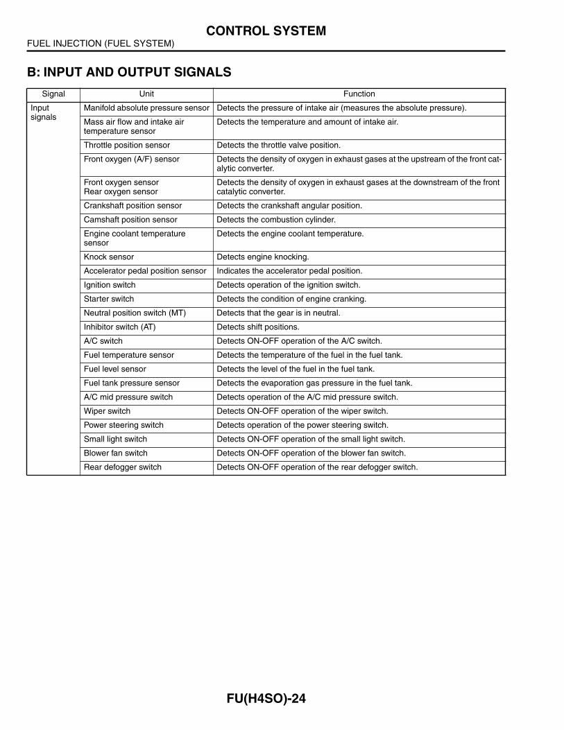
B: INPUT AND OUTPUT SIGNALS
Signal Unit Function
Input signals
Manifold absolute pressure sensor Detects the pressure of intake air (measures the absolute pressure).
Mass air flow and intake air temperature sensor
Detects the temperature and amount of intake air.
Throttle position sensor Detects the throttle valve position.
Front oxygen (A/F) sensor Detects the density of oxygen in exhaust gases at the upstream of the front cat-alytic converter.
Front oxygen sensorRear oxygen sensor
Detects the density of oxygen in exhaust gases at the downstream of the front catalytic converter.
Crankshaft position sensor Detects the crankshaft angular position.
Camshaft position sensor Detects the combustion cylinder.
Engine coolant temperature sensor
Detects the engine coolant temperature.
Knock sensor Detects engine knocking.
Accelerator pedal position sensor Indicates the accelerator pedal position.
Ignition switch Detects operation of the ignition switch.
Starter switch Detects the condition of engine cranking.
Neutral position switch (MT) Detects that the gear is in neutral.
Inhibitor switch (AT) Detects shift positions.
A/C switch Detects ON-OFF operation of the A/C switch.
Fuel temperature sensor Detects the temperature of the fuel in the fuel tank.
Fuel level sensor Detects the level of the fuel in the fuel tank.
Fuel tank pressure sensor Detects the evaporation gas pressure in the fuel tank.
A/C mid pressure switch Detects operation of the A/C mid pressure switch.
Wiper switch Detects ON-OFF operation of the wiper switch.
Power steering switch Detects operation of the power steering switch.
Small light switch Detects ON-OFF operation of the small light switch.
Blower fan switch Detects ON-OFF operation of the blower fan switch.
Rear defogger switch Detects ON-OFF operation of the rear defogger switch.
FUEL INJECTION (FUEL SYSTEM)CONTROL SYSTEM
FU(H4SO)-25
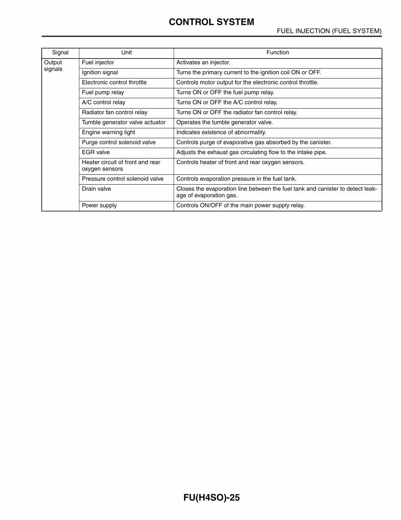
Output signals
Fuel injector Activates an injector.
Ignition signal Turns the primary current to the ignition coil ON or OFF.
Electronic control throttle Controls motor output for the electronic control throttle.
Fuel pump relay Turns ON or OFF the fuel pump relay.
A/C control relay Turns ON or OFF the A/C control relay.
Radiator fan control relay Turns ON or OFF the radiator fan control relay.
Tumble generator valve actuator Operates the tumble generator valve.
Engine warning light Indicates existence of abnormality.
Purge control solenoid valve Controls purge of evaporative gas absorbed by the canister.
EGR valve Adjusts the exhaust gas circulating flow to the intake pipe.
Heater circuit of front and rear oxygen sensors
Controls heater of front and rear oxygen sensors.
Pressure control solenoid valve Controls evaporation pressure in the fuel tank.
Drain valve Closes the evaporation line between the fuel tank and canister to detect leak-age of evaporation gas.
Power supply Controls ON/OFF of the main power supply relay.
Signal Unit Function

FUEL INJECTION (FUEL SYSTEM)CONTROL SYSTEM
FU(H4SO)-26
C: FUEL INJECTION CONTROLThe ECM receives signals from various sensors and based on them, it determines the amount of
fuel injected and the fuel injection timing. It performs the sequential fuel injection control over theentire engine operating range except during start-up of the engine.
The amount of fuel injected depends upon the length of time the injector stays open. The fuel in-jection duration is determined according to varying operating condition of the engine. For the pur-pose of achieving highly responsive and accurate fuel injection duration control, the ECM performsa new feedback control that incorporates a learning feature as detailed later.
The sequential fuel injection control is performed such that fuel is injected accurately at the timewhen the maximum air intake efficiency can be achieved for each cylinder (i.e., fuel injection is com-pleted just before the intake valve begins to open).
1. FUEL INJECTION DURATION
Fuel injection duration is basically determined as indicated below:
While cranking the engine:The duration defined below is used.
Duration of fuel injection during engine start-up ..... Determined according to the engine coolanttemperature detected by the engine coolant temperature sensor.
During normal operation:The duration is determined as follows: Basic duration of fuel injection × Correction factors + Voltage correction time
Basic duration of fuel injection ..... The basic length of time fuel is injected. This is determinedby two factors — the amount of intake air detected by the air flow sensor and the engine speedmonitored by the crankshaft position sensor.
Correction factors ..... See the next section.Voltage correction time ..... This is added to compensate for the time lag before operation of
injector that results from variation in the battery voltage.
2. CORRECTION FACTORS
The following factors are used to correct the basic duration of fuel injection in order to make the air-fuel ratio meet the requirements of varying engine operating conditions:
Air-fuel ratio feedback factor:This factor is used to correct the basic duration of fuel injection in relation to the actual enginespeed. (See the next section for more details.)
Start increment factor: This factor is used to increase the fuel injection duration only while the engine is being cranked toimprove its start ability.
Coolant-temperature-dependent increment factor:This factor is used to increase the fuel injection duration depending on engine coolant temperaturesignals to facilitate cold starting. The lower the coolant temperature, the greater becomes the incre-ment.
After-start increment factor:This factor is used to increase the fuel injection duration for a certain period immediately after
start of the engine to stabilize engine operation.The increment depends on the coolant temperature at the start of the engine.
FUEL INJECTION (FUEL SYSTEM)CONTROL SYSTEM
FU(H4SO)-27
Wide-open-throttle increment factor: This factor is used to increase the fuel injection duration depending on the relationship between thethrottle position sensor signal and air flow sensor signal.
Acceleration increment factor:This factor is used to increase the fuel injection duration to compensate for a time lag between airflow measurement and fuel injection control for better engine response to driver’s pedal operationduring acceleration.
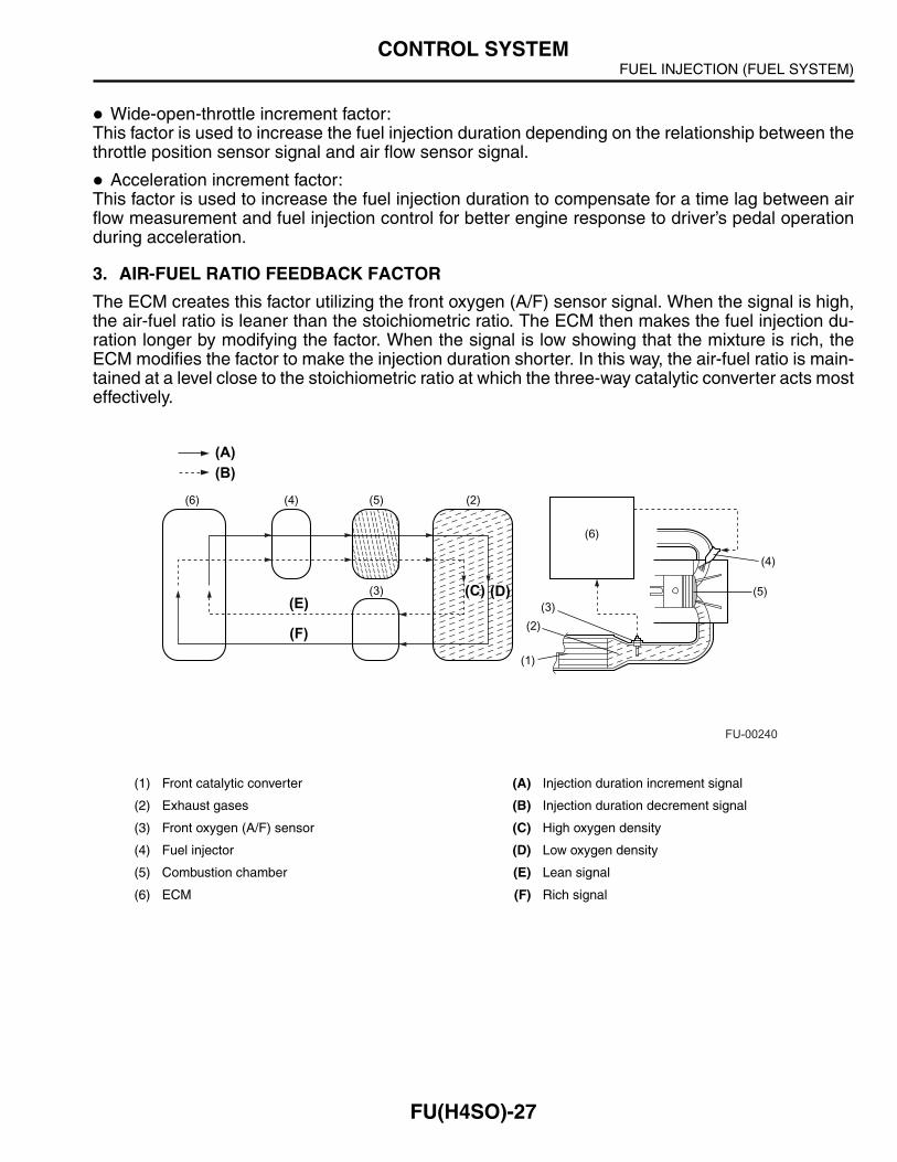
3. AIR-FUEL RATIO FEEDBACK FACTOR
The ECM creates this factor utilizing the front oxygen (A/F) sensor signal. When the signal is high,the air-fuel ratio is leaner than the stoichiometric ratio. The ECM then makes the fuel injection du-ration longer by modifying the factor. When the signal is low showing that the mixture is rich, theECM modifies the factor to make the injection duration shorter. In this way, the air-fuel ratio is main-tained at a level close to the stoichiometric ratio at which the three-way catalytic converter acts mosteffectively.
(1) Front catalytic converter (A) Injection duration increment signal
(2) Exhaust gases (B) Injection duration decrement signal
(3) Front oxygen (A/F) sensor (C) High oxygen density
(4) Fuel injector (D) Low oxygen density
(5) Combustion chamber (E) Lean signal
(6) ECM (F) Rich signal
(A)(B)
(6) (4) (5) (2)
(3)(E)
(F)
(3)
(2)
(1)
(5)
(4)
(6)
(C) (D)
FU-00240
FUEL INJECTION (FUEL SYSTEM)CONTROL SYSTEM
FU(H4SO)-28
4. LEARNING FEATURE
The air-fuel ratio feedback control includes a learning feature, which contributes to more accurateand responsive control.
In the air-fuel ratio feedback control, the ECM calculates the necessary amount of correctionbased on data from the front oxygen (A/F) sensor and adds the result to the basic duration (whichis stored in the ECM’s memory for each condition defined by the engine speed and various loads.)
Without a learning feature, the ECM carries out the above-mentioned process every time. Thismeans that if the amount of necessary correction is large, the air-fuel ratio feedback control be-comes less responsive and less accurate.
The learning feature enables the ECM to store the amount of correction into memory, and takesit into account with the basic fuel injection duration to create a new reference fuel injection duration.Using the reference duration as the basic duration for the injection a few times later, the ECM canreduce the amount of correction and thus make its feedback control more accurate and responsiveto changes in the air-fuel ratio due to difference in driving condition and sensor/actuator character-istics that may result from unit-to-unit variation or aging over time.

FUEL INJECTION (FUEL SYSTEM)CONTROL SYSTEM
FU(H4SO)-29
D: IGNITION CONTROLThe ECM determines operating condition of the engine based on signals from the manifold ab-
solute pressure sensor, engine coolant temperature sensor, intake air temperature sensor, crank-shaft position sensor and other sources. The ECM then selects the ignition timing most appropriatefor the condition thus determined from those stored in its memory and outputs at that timing a pri-mary current OFF signal to the igniter to initiate ignition.
This control uses a quick-to-response learning feature by which the data stored in the ECM mem-ory is processed in comparison with information from various sensors and switches.
Thus, the ECM can always perform optimum ignition timing taking into account the output, fuelefficiency, exhaust gas, and other factors for every engine operating condition.
Ignition control during start-upEngine speed fluctuates during start of the engine, so the ECM cannot control the ignition timing.During that period, the ignition timing is fixed at 10° BTDC by using the 10° signal from the crank-shaft position sensor.
Crankshaft position sensor
Camshaft position sensor
Engine coolant temperature sensor
Mass air flow and intake air temperature sensor
Manifold absolute pressure sensor
Knock sensor
Throttle position sensor
Neutral position switch (MT)Inhibitor switch (AT)
A/C switch
Ignition coil and igniter assembly
#1 Spark plug
#2 Spark plug
#3 Spark plug
#4 Spark plug
ECM
FU-02412
FUEL INJECTION (FUEL SYSTEM)CONTROL SYSTEM
FU(H4SO)-30
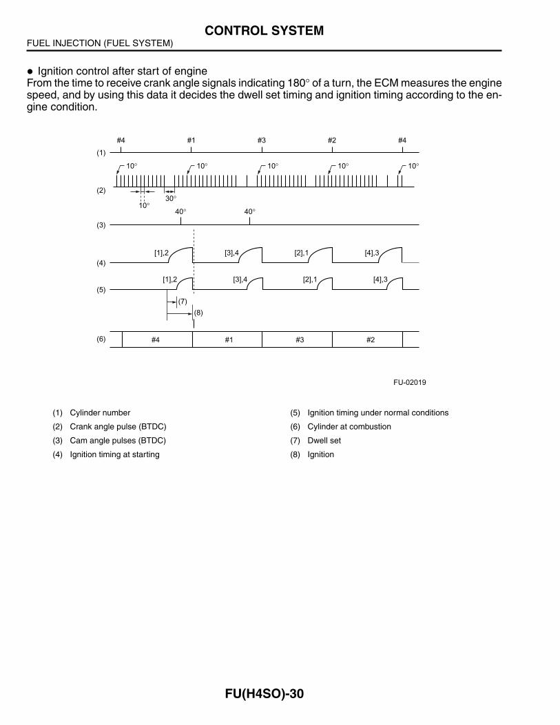
Ignition control after start of engineFrom the time to receive crank angle signals indicating 180° of a turn, the ECM measures the enginespeed, and by using this data it decides the dwell set timing and ignition timing according to the en-gine condition.
(1) Cylinder number (5) Ignition timing under normal conditions
(2) Crank angle pulse (BTDC) (6) Cylinder at combustion
(3) Cam angle pulses (BTDC) (7) Dwell set
(4) Ignition timing at starting (8) Ignition
(1)
(2)
(3)
(4)
(5)
(6)
#4 #1 #3 #2 #4
10°30°
40° 40°
10° 10° 10° 10° 10°
(7)
(8)
#4 #1 #3 #2
[4],3[2],1[3],4[1],2
[4],3[2],1[3],4[1],2
FU-02019
FUEL INJECTION (FUEL SYSTEM)CONTROL SYSTEM
FU(H4SO)-31
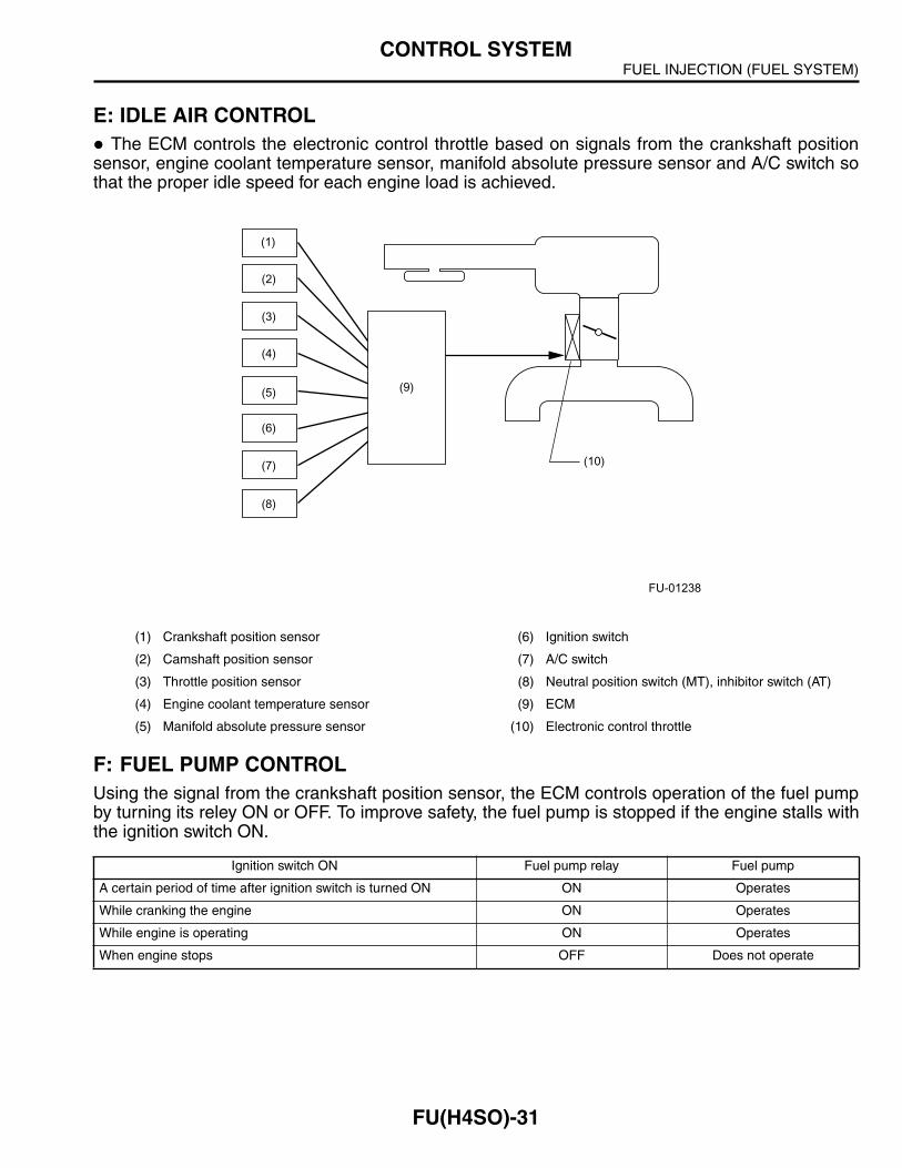
E: IDLE AIR CONTROLThe ECM controls the electronic control throttle based on signals from the crankshaft position
sensor, engine coolant temperature sensor, manifold absolute pressure sensor and A/C switch sothat the proper idle speed for each engine load is achieved.
F: FUEL PUMP CONTROLUsing the signal from the crankshaft position sensor, the ECM controls operation of the fuel pumpby turning its reley ON or OFF. To improve safety, the fuel pump is stopped if the engine stalls withthe ignition switch ON.
(1) Crankshaft position sensor (6) Ignition switch
(2) Camshaft position sensor (7) A/C switch
(3) Throttle position sensor (8) Neutral position switch (MT), inhibitor switch (AT)
(4) Engine coolant temperature sensor (9) ECM
(5) Manifold absolute pressure sensor (10) Electronic control throttle
Ignition switch ON Fuel pump relay Fuel pump
A certain period of time after ignition switch is turned ON ON Operates
While cranking the engine ON Operates
While engine is operating ON Operates
When engine stops OFF Does not operate
(10)
(3)
(2)
(4)
(5)
(6)
(7)
(8)
(1)
(9)
FU-01238
FUEL INJECTION (FUEL SYSTEM)ON-BOARD DIAGNOSIS SYSTEM
FU(H4SO)-32
6. On-board Diagnosis SystemA: GENERAL
The on-board diagnosis system detects and indicates a fault by generating a code correspondingto each fault location. The malfunction indicator light on the combination meter indicates occurrenceof a fault or abnormality.
When the malfunction indicator light comes on as a result of detection of a fault by the ECM, thecorresponding diagnostic trouble code (DTC) and freeze frame engine condition are stored in theECM.
On the OBD-II conformable car, it is necessary to connect the SUBARU Select Monitor (SSM) orGeneral Scan Tool (GST) to the data link connector in order to check the DTC.
The SSM and GST can be used for erasing DTCs. These can also read freeze frame data in ad-dition to other pieces of engine data.
If there is a failure involving sensors, which may affect drive control of the vehicle, the fail-safefunction ensures minimum level of drivability.
B: FAIL-SAFE FUNCTIONFor a sensor or switch that has been judged to be faulty by the on-board diagnosis, the ECM gen-erates a pseudo signal to keep the vehicle operational. (The control becomes degraded.)