fuel injection systems
TRANSCRIPT
INTERNAL COMBUSTION ENGINES-II Fuel Injection System
I C ENGINES – II : Fuel Injection System
Introduction
• Fuel-Injection System is vital to the working and
performance of CI engine
• This system serves the purpose of initiating and
controlling the combustion to meet the demand
requirements
• Fuel is injected into combustion chamber towards
the end of compression. It is atomized as it enters
under high velocity and the droplets get vaporized
to form a fuel-air mixture. Due to continued heat
transfer from hot air to fuel, the fuel reaches to its
self ignition temperature to ignite spontaneously
I C ENGINES – II : Fuel Injection System
Introduction
initiating combustion. Depending upon the demand
requirements the fuel injection system continues to
deliver the fuel during initial part of combustion.
Functional Requirements of an Injection System
For proper engine operation and satisfactory performance,
the following requirements must be met by the Fuel
Injection (FI) System
Accurate metering of fuel injected per cycle to meet
changing demand of speed & load
Precise timing of fuel injection in the cycle to ensure
I C ENGINES – II : Fuel Injection System
performance; power, fuel economy, emissions
Proper control of rate of injection to achieve desired
heat release during combustion without knocking.
Proper atomization of fuel into fine droplets
Proper spray pattern to ensure rapid mixing of fuel & air
Uniform distribution of fuel droplets throughout the
combustion chamber.
To supply equal quantities of metered fuel to all
cylinders in case of multi cylinder engines.
No lag during beginning and end of injection to eliminate
dribbling of fuel droplets into the cylinder
I C ENGINES – II : Fuel Injection System
Classification of Injection System :
Air Injection system and Solid Injection system
Air Injection system : Fuel is forced by means of
compressed air. Good mixing with higher mep. It
requires compressor. Ability to use high viscosity fuel.
Not much in use
Solid Injection system : Liquid fuel is injected directly
into combustion chamber. Solid injection systems can
be classified into ;
i) Individual pump and nozzle system
ii) Unit Injector system
iii) Common rail system
iv) Distributor system
I C ENGINES – II : Fuel Injection System
All the FI systems comprise of following components:
Fuel tank
Fuel feed pump to supply fuel from fuel tank to FI system
Injection pump to meter and pressurize the fuel for
injection
Governor to ensure that the amount of fuel injected is in
accordance with variation of load
Injector to take the fuel from the pump and distribute it in
the combustion chamber by atomizing it into fine
droplets
Fuel filters to prevent dust and abrasive particles from
entering the pump & injectors to reduce wear & tear of
components
I C ENGINES – II : Fuel Injection System
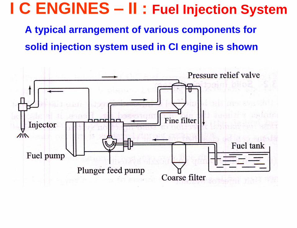
A typical arrangement of various components for
solid injection system used in CI engine is shown
I C ENGINES – II : Fuel Injection System
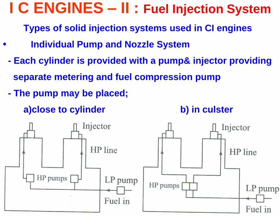
Types of solid injection systems used in CI engines
• Individual Pump and Nozzle System
- Each cylinder is provided with a pump& injector providing
separate metering and fuel compression pump
- The pump may be placed;
a)close to cylinder b) in culster
I C ENGINES – II : Fuel Injection System
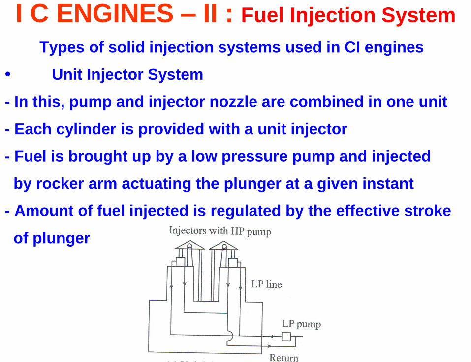
Types of solid injection systems used in CI engines
• Unit Injector System
- In this, pump and injector nozzle are combined in one unit
- Each cylinder is provided with a unit injector
- Fuel is brought up by a low pressure pump and injected
by rocker arm actuating the plunger at a given instant
- Amount of fuel injected is regulated by the effective stroke
of plunger
I C ENGINES – II : Fuel Injection System
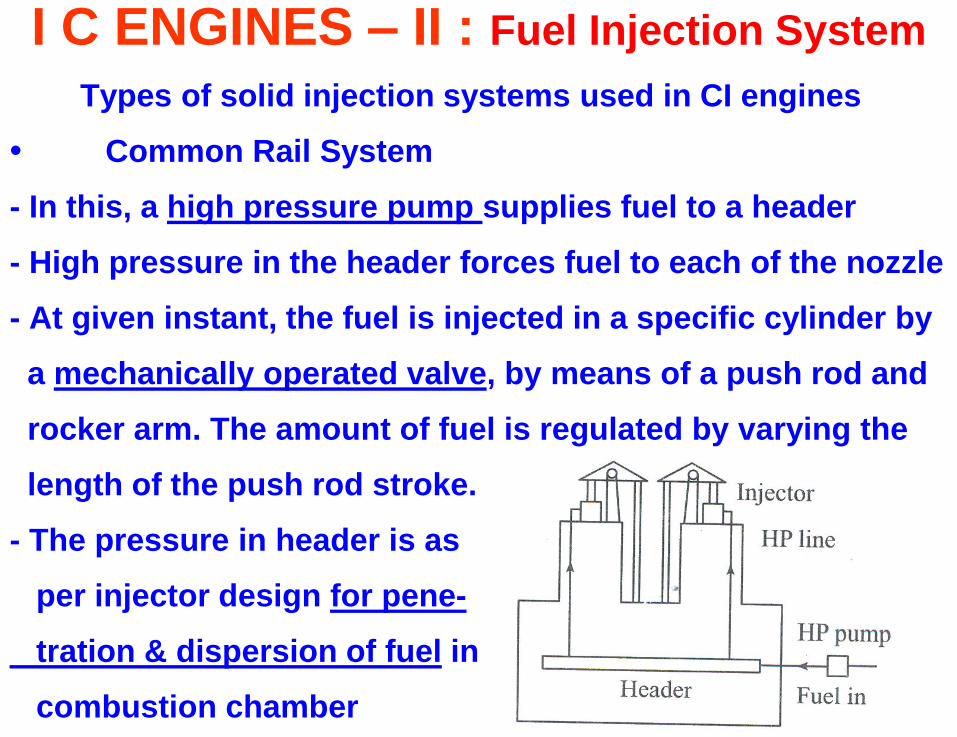
Types of solid injection systems used in CI engines
• Common Rail System
- In this, a high pressure pump supplies fuel to a header
- High pressure in the header forces fuel to each of the nozzle
- At given instant, the fuel is injected in a specific cylinder by
a mechanically operated valve, by means of a push rod and
rocker arm. The amount of fuel is regulated by varying the
length of the push rod stroke.
- The pressure in header is as
per injector design for pene-
tration & dispersion of fuel in
combustion chamber
I C ENGINES – II : Fuel Injection System
Types of solid injection systems used in CI engines
• Distributor System
- In this system, the pump pressurizes, meters and times the
fuel by supplying it to a rotating distributor for injection to
each cylinder. A uniform distribution of fuel is automatically
ensured because of one metering element.
I C ENGINES – II : Fuel Injection System
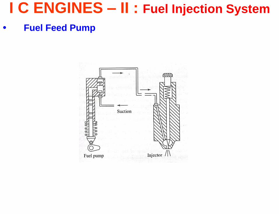
• Fuel Feed Pump
- It is of spring loaded plunger type. The plunger is actuated
through a push rod from the cam shaft.
- At the minimum lift position of cam the spring force on the
the plunger creates suction causes fuel flow from the main
tank into pump. When cam turn to maximum lift position the
plunger lifts upwards. At the same time inlet valve is closed
and fuel is forced through the outlet valve.
When the operating pressure gets released, the plunger
return spring ceases to function resulting in varying of the
pumping stroke under varying engine load according to the
quantity of fuel required by the injection pump.
I C ENGINES – II : Fuel Injection System
• Fuel Feed Pump
I C ENGINES – II : Fuel Injection System
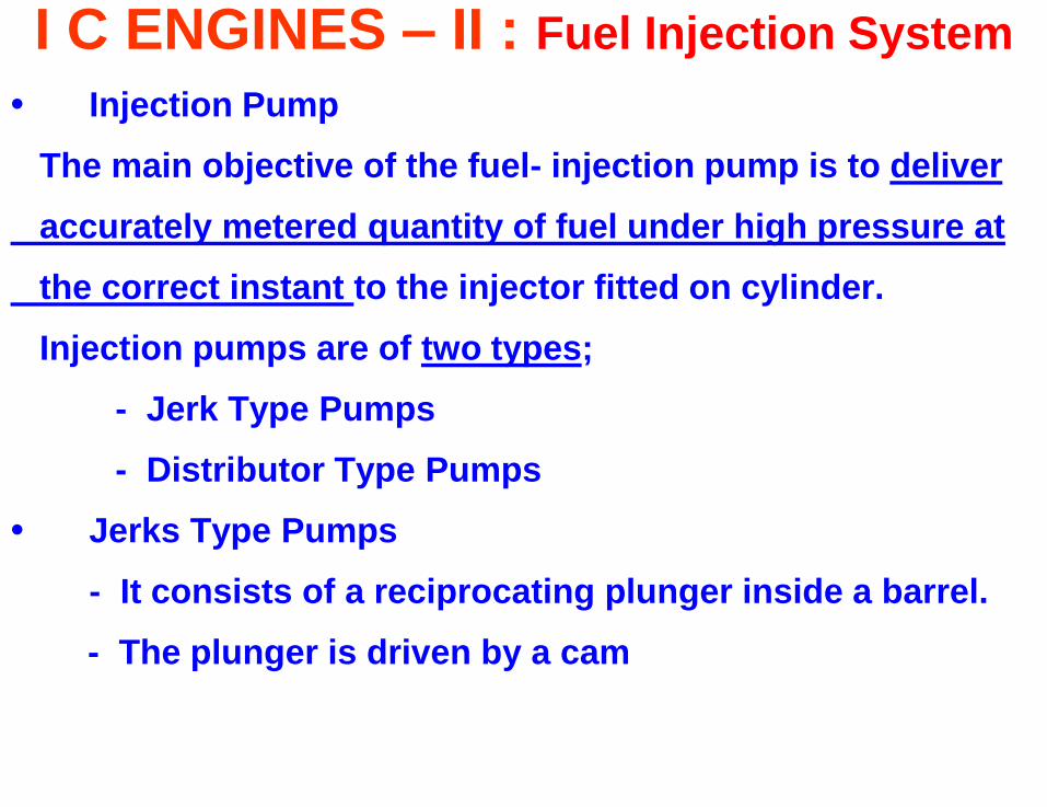
• Injection Pump
The main objective of the fuel- injection pump is to deliver
accurately metered quantity of fuel under high pressure at
the correct instant to the injector fitted on cylinder.
Injection pumps are of two types;
- Jerk Type Pumps
- Distributor Type Pumps
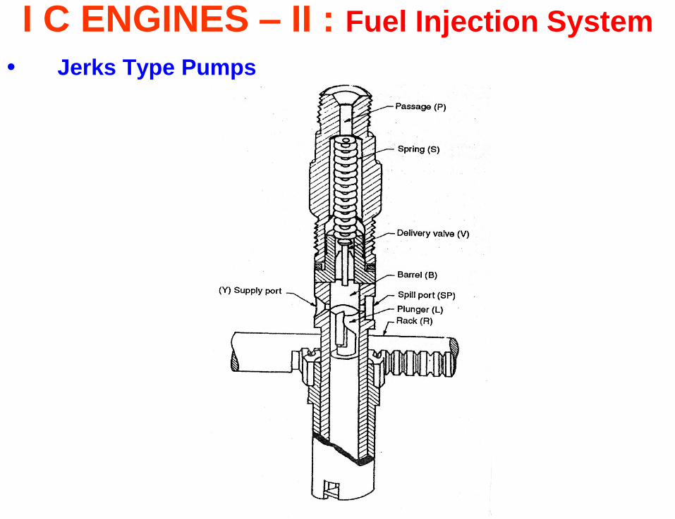
• Jerks Type Pumps
- It consists of a reciprocating plunger inside a barrel.
- The plunger is driven by a cam
I C ENGINES – II : Fuel Injection System
• Jerks Type Pumps
I C ENGINES – II : Fuel Injection System
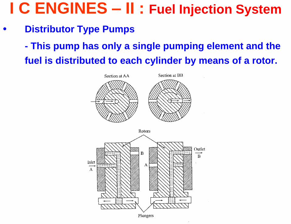
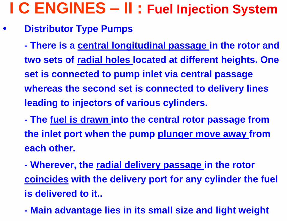
• Distributor Type Pumps
- This pump has only a single pumping element and the
fuel is distributed to each cylinder by means of a rotor.
I C ENGINES – II : Fuel Injection System
• Distributor Type Pumps
- There is a central longitudinal passage in the rotor and
two sets of radial holes located at different heights. One
set is connected to pump inlet via central passage
whereas the second set is connected to delivery lines
leading to injectors of various cylinders.
- The fuel is drawn into the central rotor passage from
the inlet port when the pump plunger move away from
each other.
- Wherever, the radial delivery passage in the rotor
coincides with the delivery port for any cylinder the fuel
is delivered to it..
- Main advantage lies in its small size and light weight
I C ENGINES – II : Fuel Injection System
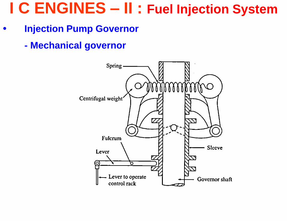
• Injection Pump Governor
- Mechanical governor
I C ENGINES – II : Fuel Injection System
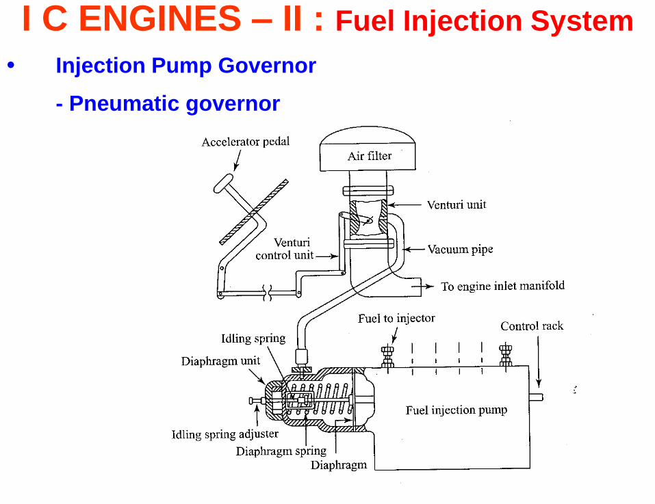
• Injection Pump Governor
- Pneumatic governor
I C ENGINES – II : Fuel Injection System
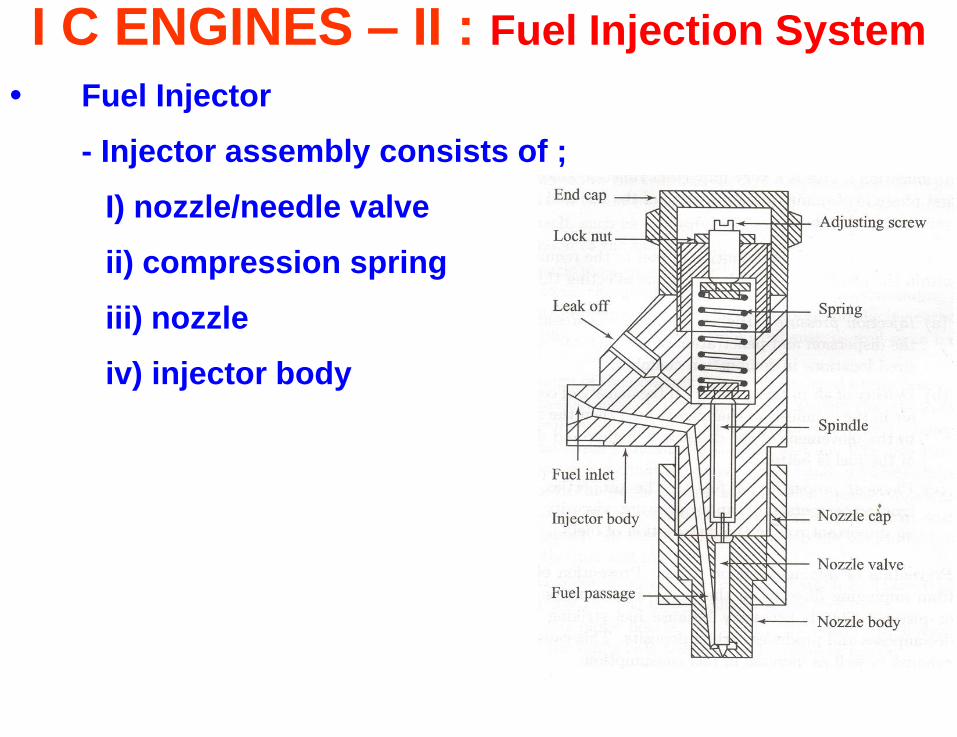
• Fuel Injector
- Injector assembly consists of ;
I) nozzle/needle valve
ii) compression spring
iii) nozzle
iv) injector body
I C ENGINES – II : Fuel Injection System
• Fuel Injector
- Nozzle should fulfill the following functions
i) Atomization
ii) Distribution of fuel :
Factors affecting fuel distribution
# Injection pressure : dispersion, penetration
# Density of air in the cylinder: resistance to movement
# Physical properties of fuel: self ignition temp., vapour
press., viscosity, etc.
iii) Prevention of impingement on walls: decomposition
iv) Mixing : in case of non-turbulent type of combustion
chamber
I C ENGINES – II : Fuel Injection System
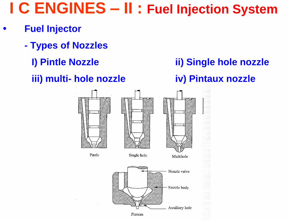
• Fuel Injector
- Types of Nozzles
I) Pintle Nozzle ii) Single hole nozzle
iii) multi- hole nozzle iv) Pintaux nozzle
I C ENGINES – II : Fuel Injection System
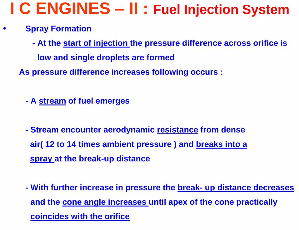
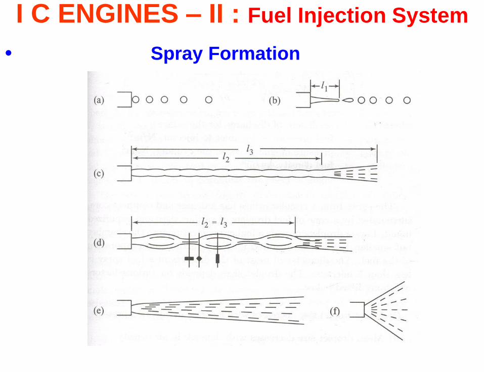
• Spray Formation
- At the start of injection the pressure difference across orifice is
low and single droplets are formed
As pressure difference increases following occurs :
- A stream of fuel emerges
- Stream encounter aerodynamic resistance from dense
air( 12 to 14 times ambient pressure ) and breaks into a
spray at the break-up distance
- With further increase in pressure the break- up distance decreases
and the cone angle increases until apex of the cone practically
coincides with the orifice
I C ENGINES – II : Fuel Injection System
• Spray Formation
I C ENGINES – II : Fuel Injection System
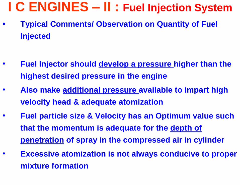
• Typical Comments/ Observation on Quantity of Fuel
Injected
• Fuel Injector should develop a pressure higher than the
highest desired pressure in the engine
• Also make additional pressure available to impart high
velocity head & adequate atomization
• Fuel particle size & Velocity has an Optimum value such
that the momentum is adequate for the depth of
penetration of spray in the compressed air in cylinder
• Excessive atomization is not always conducive to proper
mixture formation
I C ENGINES – II : Fuel Injection System
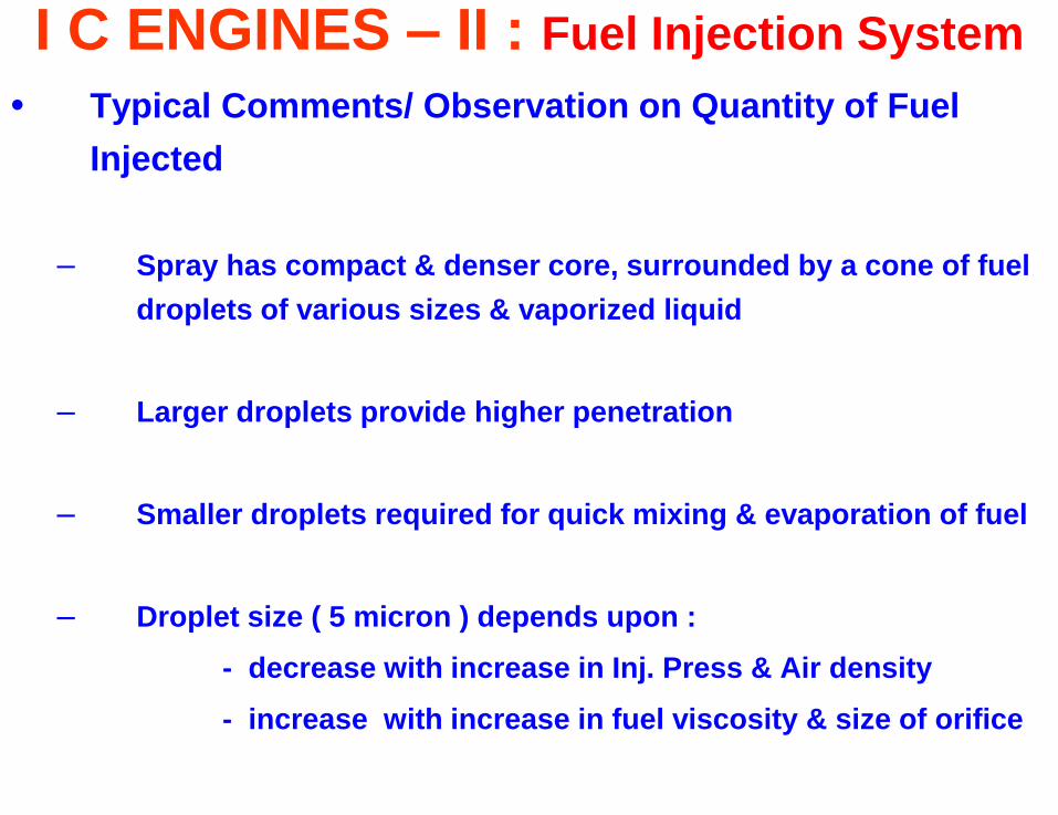
• Typical Comments/ Observation on Quantity of Fuel
Injected
– Spray has compact & denser core, surrounded by a cone of fuel
droplets of various sizes & vaporized liquid
– Larger droplets provide higher penetration
– Smaller droplets required for quick mixing & evaporation of fuel
– Droplet size ( 5 micron ) depends upon :
- decrease with increase in Inj. Press & Air density
- increase with increase in fuel viscosity & size of orifice
I C ENGINES – II : Fuel Injection System
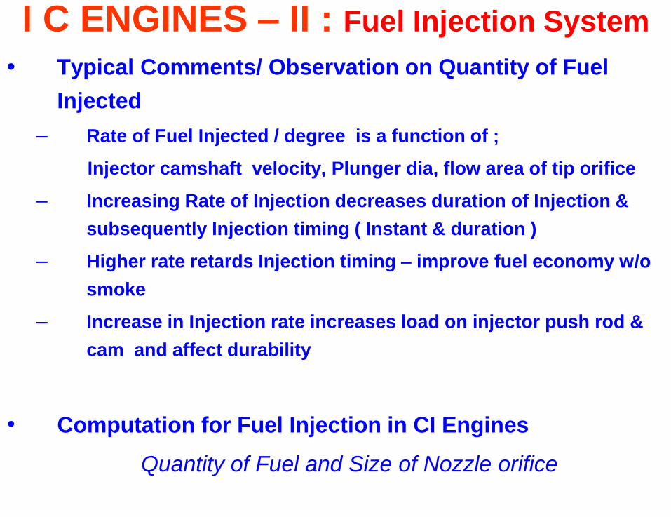
• Typical Comments/ Observation on Quantity of Fuel
Injected
– Rate of Fuel Injected / degree is a function of ;
Injector camshaft velocity, Plunger dia, flow area of tip orifice
– Increasing Rate of Injection decreases duration of Injection &
subsequently Injection timing ( Instant & duration )
– Higher rate retards Injection timing – improve fuel economy w/o
smoke
– Increase in Injection rate increases load on injector push rod &
cam and affect durability
• Computation for Fuel Injection in CI Engines
Quantity of Fuel and Size of Nozzle orifice
I C ENGINES – II : Fuel Injection System
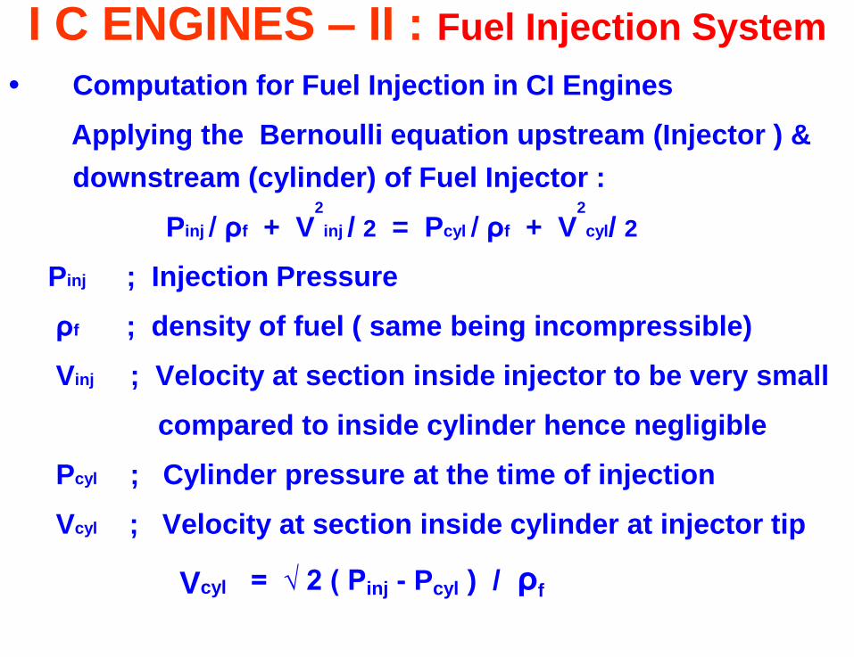
• Computation for Fuel Injection in CI Engines
Applying the Bernoulli equation upstream (Injector ) &
downstream (cylinder) of Fuel Injector :
Pinj / ρf + V2
inj / 2 = Pcyl / ρf + V2
cyl/ 2
Pinj ; Injection Pressure
ρf ; density of fuel ( same being incompressible)
Vinj ; Velocity at section inside injector to be very small
compared to inside cylinder hence negligible
Pcyl ; Cylinder pressure at the time of injection
Vcyl ; Velocity at section inside cylinder at injector tip
Vcyl = √ 2 ( Pinj - Pcyl ) / ρf
I C ENGINES – II : Fuel Injection System
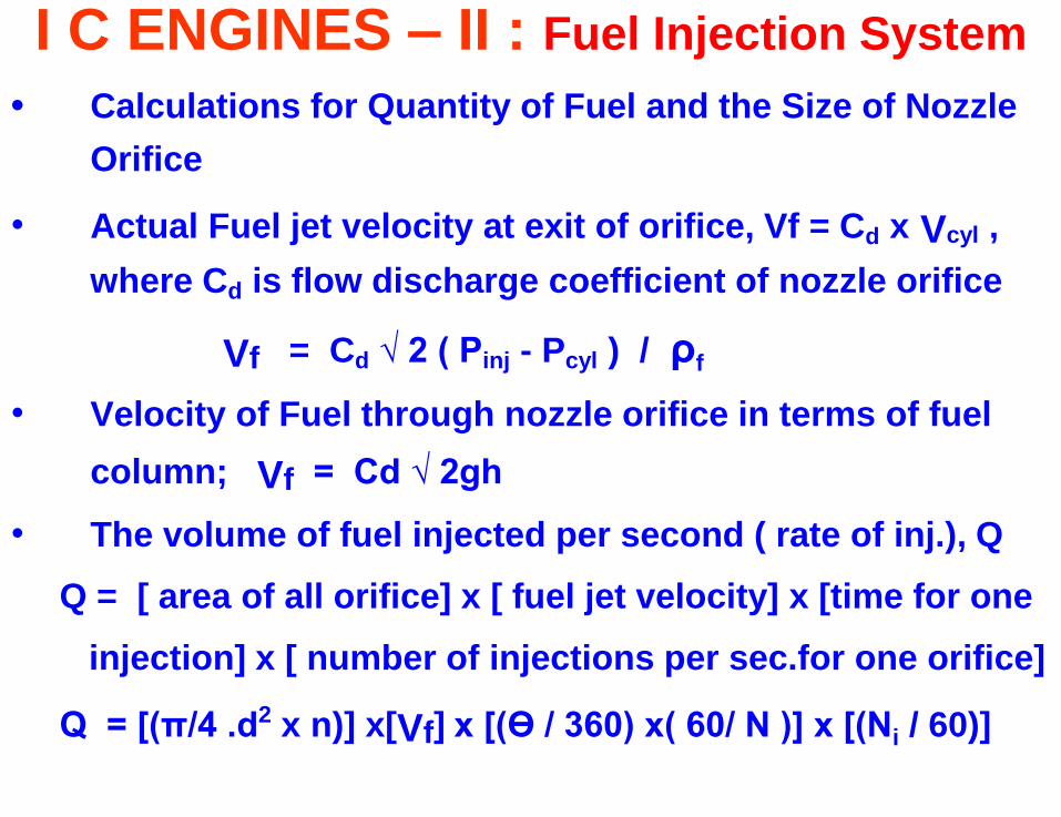
• Calculations for Quantity of Fuel and the Size of Nozzle
Orifice
• Actual Fuel jet velocity at exit of orifice, Vf = Cd x Vcyl ,
where Cd is flow discharge coefficient of nozzle orifice
Vf = Cd √ 2 ( Pinj - Pcyl ) / ρf
• Velocity of Fuel through nozzle orifice in terms of fuel
column; Vf = Cd √ 2gh
• The volume of fuel injected per second ( rate of inj.), Q
Q = [ area of all orifice] x [ fuel jet velocity] x [time for one
injection] x [ number of injections per sec.for one orifice]
Q = [(π/4 .d2 x n)] x[Vf] x [(Ө / 360) x( 60/ N )] x [(Ni / 60)]
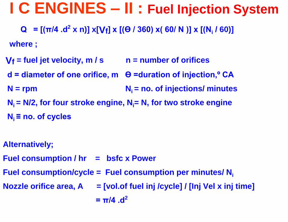
I C ENGINES – II : Fuel Injection System
Q = [(π/4 .d2 x n)] x[Vf] x [(Ө / 360) x( 60/ N )] x [(Ni / 60)]
where ;
Vf = fuel jet velocity, m / s n = number of orifices
d = diameter of one orifice, m Ө =duration of injection,º CA
N = rpm Ni = no. of injections/ minutes
Ni = N/2, for four stroke engine, Ni= N, for two stroke engine
Ni ≡ no. of cycles
Alternatively;
Fuel consumption / hr = bsfc x Power
Fuel consumption/cycle = Fuel consumption per minutes/ Ni
Nozzle orifice area, A = [vol.of fuel inj /cycle] / [Inj Vel x inj time]
= π/4 .d2
I C ENGINES – II : Fuel Injection System
• Functional Requirements of an Injection System
- Accurate metering /Precise timing / Proper control of rate
/atomization/spray pattern /Uniform distribution /
equal quantities /No lag
• Fuel Injection system : Pump, Nozzle System and other
components
• Spray Formation