(owts) design and construction standards
TRANSCRIPT

On-site Wastewater Treatment System (OWTS)
Design and Construction Standards
Monroe County Department of Public Health Division of Environmental Health
Bureau of Public Health Engineering 111 Westfall Road
Rochester, NY 14620
September 2015


OWTS DESIGN AND CONSTRUCTION STANDARDS 2015 VERSION MONROE COUNTY, NEW YORK
This document, the “On-site Wastewater Treatment System Design and Construction Standards for Monroe County, New York”, was developed by the Staff of the Monroe County Department of Public Health Division of Environmental Health – Bureau of Public Health Engineering. These Standards, when adopted, shall replace the previous “Individual Sewage Disposal Handbook for Monroe County, New York” dated July 1992. Questions regarding these design and construction standards can be directed to: John J. Frazer, P.E. Manager of Environmental Health Monroe County Department of Public Health 111 Westfall Road Rochester, New York 14620 (585)-753-5476
PAGE 2 OF 40


OWTS DESIGN AND CONSTRUCTION STANDARDS 2015 VERSION MONROE COUNTY, NEW YORK
Table of Contents Introduction……………………………………………………………….……………………4
I. Definitions………………………………………………………………………………………5 II. Regulation by Other Agencies……………………………………………………..…………..7
III. Sewage Flows…………………………………………………….……………………………..8 IV. Soil and Site Appraisal……………………………………………………...………………….9
a. Site Investigation………………………………………...………………………………9 b. Separation Requirements…………………………………………………..…………….9 c. Soil Investigation……………………………………………...………………………..11 d. Soil Percolation Test……………………………………………...…………………….11
V. House Sewer…………………………………………….……………………………………..13 VI. Septic Tanks…………………………………………………………….……………………..13
a. General Information…………………………………..………………………………..13 b. Design and Installation………………………………………………..………………..14
VII. Distribution Devices…………………………………………………………………………..17 a. Gravity Distribution…………………………………………………...………………..17 b. Pressure Distribution and Dosing…………………………………………...………….18
VIII. Conventional Subsurface Distribution Systems…………………………………………….19 a. General for all Treatment Systems………………………………………………..……19 b. Absorption Trench Systems……………………………………………...…………….19 c. Gravelless Absorption Systems………………………………………………...………23 d. Deep Absorption Trench Systems……………………………………………...………24 e. Shallow Absorption Trench Systems……………………………………………..……25 f. Cut and Fill Systems……………………………………………………...…………….25 g. Absorption Bed Systems……………………………………………………………….26 h. Seepage Pits………………………………………………………………….…………28
IX. Alternative Systems………………………………………………………………….………..31 a. General for Alternative Systems……………………………………………………….31 b. Raised Systems…………………………………………………………..……………..31 c. Mound Systems…………………………………………………………..…………….34 d. Intermittent Sand Filters……………………………………………….……………….36 e. Evapo-Transpiration Systems………………………………………………….……….38
X. Other Systems……………………………………………………………………...………….39 a. Holding Tanks……………………………………………………...…………………..39 b. Non-Waterborne Systems……………………………………………..………………..39
XI. Specific Waivers………………………………………………………...……………………..40 Appendices A Tables B Figures (Standard Details)
PAGE 3 OF 40


OWTS DESIGN AND CONSTRUCTION STANDARDS 2015 VERSION MONROE COUNTY, NEW YORK
Introduction These standards apply to on-site wastewater treatment systems (OWTS) in Monroe County serving newly constructed residential properties and receiving sewage without the admixture of industrial wastes or other wastes, as defined in Environmental Conservation Law, Section 17-0701, in quantities of less than 1,000 gallons per day (gpd). These standards shall also apply to replacement systems and repairs, when deemed feasible by the Monroe County Department of Public Health (MCDPH). These standards have been produced to provide guidance in uniformly implementing the rules and regulations of the State of New York Title 10, Department of Health, Chapter II, Part 75, Standards for Individual Onsite Water Supply and Individual Onsite Wastewater Treatment Systems. These standards have been developed to guide the effective design, construction, and maintenance of individual on-site wastewater treatment systems (OWTS) and can be effectively used by design professionals, builders, contractors, community officials, and homeowners. Part 75 of the NYSDOH’s Administrative Rules and Regulations (10NYCRR 75) requires that individual sewage treatment systems shall be designed and constructed in accordance with 10NYCRR Appendix 75-A. The standards set forth herein have been developed to meet or exceed the criteria presented in Appendix 75-A of Title 10 the Official Compilation of Codes, Rules and Regulations of the State of New York, as allowed pursuant to Section 75-A.2(b). Adequate on-site wastewater treatment systems provide for a safe, sanitary means of treating wastewater. Many gastrointestinal illnesses can be transmitted by water, food, insects, and pets that have been contaminated by human waste. Properly designed, constructed, and maintained sewage treatment systems minimize the possibility of disease transmission and potential for contamination of ground and surface waters. Public health and overall quality of life is thereby enhanced.
PAGE 4 OF 40


OWTS DESIGN AND CONSTRUCTION STANDARDS 2015 VERSION MONROE COUNTY, NEW YORK
I. Definitions
As used in this document, the following words and terms shall have the indicated meaning:
Absorption Area - an area to which wastewater is distributed for infiltration to the soil.
Absorption Field - the area to which sewage is distributed for infiltration to the soil by means of a network of pipes.
Absorption Trench - a long narrow area which includes a pipe for the distribution of septic tank effluent.
Aerobic Treatment Unit - a system that provides for the biological decomposition of the organic portion of the wastewater by mechanical aeration of the wastewater.
Aggregate - washed gravel or crushed stone ¾ - 1½ inches in diameter.
Application Rate - the rate at which septic tank effluent is applied to a subsurface absorption area, for design purposes, expressed in gallons per day per square foot (gpd/sq. ft.).
Baffle - a flow deflecting device used in septic tanks and distribution boxes to inhibit the discharge of floating solids, reduce the amount of settleable solids that exit, and reduce the exit velocity of the wastewater.
Barrier Material – a permeable geotextile, untreated building paper, or 4” thick layer of hay or straw
Building Sewer - that part of the drainage system which extends from the end of the building drain and conveys wastewater to the sewage system or sewer.
Cleanout - an opening providing access to part of the sewage system.
Curtain Drain - a subsurface drain designed and constructed to control groundwater and surface water intrusion into the area of the sewage system.
Department – Monroe County Department of Public Health
Design Professional - a person licensed or registered in the State of New York and authorized by the State Education Law to design the systems described in the standards.
Director – The Monroe County Director of Public Health or a designated representative.
Distribution Device - a device used to uniformly distribute sewage to the absorption area.
PAGE 5 OF 40

OWTS DESIGN AND CONSTRUCTION STANDARDS 2015 VERSION MONROE COUNTY, NEW YORK
Distribution Line - the perforated pipe used to distribute wastewater to the absorption area.
Drinking Water - water whose physical, chemical and biological quality is or is intended to be satisfactory for human consumption, food preparation or culinary purposes.
Effective Grain Size - a measure of the diameter of soil particles, when compared to a theoretical material having an equal transmission constant. It is the dimensions of that mesh screen which will permit 10 percent of the sample to pass and will retain 90 percent.
Enhanced Treatment - The biological and physical treatment of wastewater to reduce the amount of biochemical oxygen demand (BOD) and total suspended solids (TSS) of wastewater effluent prior to distribution to an absorption area.
Enhanced Treatment Unit (ETU) - Pre-manufactured structures that provide enhanced treatment of wastewater prior to discharge to a subsurface soil absorption area.
Gas Baffle - a device on the outlet of a septic tank which deflects gas bubbles away from the outlet and reduces the carryover of solid particles from the septic tank.
Groundwater - subsurface water, including seasonally high groundwater, occupying the saturation zone from which wells and springs are fed.
Heavy Equipment - all equipment which would result in the compaction of the design absorption area at a depth equivalent to the design depth of the distribution lines.
Infiltration - the flow or movement of water into the interstices or pores of a soil through the soil interface.
Invert - the floor, bottom, or lowest point of the inside cross section of a pipe.
Percolation - the movement of water through the pores of a soil or other porous medium following infiltration through the soil interface.
Permeability - a measure of the rate of movement of liquid through soil.
Responsible Management Entity (RME) - A legal entity with the requisite managerial, financial and technical capacity to ensure long-term management of residential wastewater treatment systems. RMEs may include: sewer districts, utilities, municipal authorities or other entities with the authority to enforce and the capacity to finance the long-term operation and maintenance requirements necessary to ensure residential wastewater treatment systems are functioning properly.
Scum - the wastewater material which is less dense than water and floats on top of the water.
PAGE 6 OF 40

OWTS DESIGN AND CONSTRUCTION STANDARDS 2015 VERSION MONROE COUNTY, NEW YORK
Sewage - the combination of human and household waste with water which is discharged to the home plumbing system including the waste from a flush toilet, bath, sink, lavatory, dishwashing or laundry machine, or the water-carried waste from any other fixture, equipment or machine.
Stabilized Rate of Percolation - the rate corresponding to two consecutive equal or near equal percolation test results.
Tire Derived Aggregate (TDA) - Aggregate manufactured from waste tires to a similar size distribution as conventional gravel or stone aggregate and used as alternative to gravel or stone aggregate in soil absorption areas.
Useable Soil - unless otherwise stated, a soil with a percolation rate from one(1) to faster than sixty(60) min/in with a compatible soil classification.
Wastewater - any water discharged from a house through a plumbing fixture to include, but not limited to, sewage and any water or waste from a device (e.g., water softener brine) which is produced in the house or property.
Watercourse - a visible path through which surface water travels on a regular basis. Drainage areas which contain water only during and immediately after a rainstorm shall not be considered a watercourse.
Watershed - an area of drainage for a body of water that serves as a source of drinking water and for which watershed rules and regulations have been adopted by the Commissioner.
Well head area - the area surrounding a well which includes the cone of influence (where the drawdown of groundwater causes groundwater flow).
Wetland - an area(s) of marshes or swamps which have been designated as such by the State Department of Environmental Conservation or other agency having jurisdiction. Marshes or swamps that have not been classified by an agency as a wetland shall not be treated for design purposes as a wetland.
II. Regulation by Other Agencies
a) Where sewage treatment systems are to be located on the watershed(s) or well head
area(s) of public water supplies, the rules and regulations enacted by the State Department of Health for the protection of these supplies must be observed.
b) This regulation establishes the minimum standards acceptable in Monroe County.
c) When individual sewage systems overlay a drinking water aquifer, this Department may
establish population density limits and minimum lot sizes for residential development with on-site sewage treatment systems.
PAGE 7 OF 40

OWTS DESIGN AND CONSTRUCTION STANDARDS 2015 VERSION MONROE COUNTY, NEW YORK
III. Sewage Flows a) Roof, footing, garage, cellar and surface water drainage must be excluded from the
system. Water softener, water recharge and backwash wastes normally are not to be discharged to the system unless a separate subsurface discharge to an area 250 feet from wells or water courses is unavailable.
b) Designs for new construction shall be based upon a minimum daily flow of 110 gallons per day per bedroom. Other design flows listed in Table 1 may be applicable for systems receiving wastewater from dwellings equipped with older plumbing fixtures or waterless toilets.
c) All sewage and wastewater (terms defined in section I) shall be discharged to the OWTS.
Table 1 Daily Design Flows
Plumbing Fixtures (based on manufactured date)
Minimum Design Flow (gallons per day per bedroom)
Post-1994 Fixtures 1.6 gallons/flush toilets 2.5 gallons/minute faucets and showerheads
110
Pre-1994 Fixtures 3.5 gallons/flush toilets 3.0 gallons/minute faucets and showerheads
130
Pre-1980 Fixtures 3.5+ gallons/flush toilets 3.0+ gallons/minute faucets and showerheads
150
Waterless Toilets (e.g., composter) (graywater discharge only) 75
PAGE 8 OF 40

OWTS DESIGN AND CONSTRUCTION STANDARDS 2015 VERSION MONROE COUNTY, NEW YORK
IV. Soil and Site Appraisal
a) Site Investigation.
1) Areas lower than the 10 year flood level are unacceptable for on-site systems. Slopes greater than 15% are also unacceptable.
2) There must be at least four feet of useable soil available above rock, unsuitable soil, and high seasonal groundwater for the installation of a conventional absorption field system (VIII.(b)). In Monroe County, where private wells are used for water supply in the vicinity of the OWTS, four feet of useable soil must be available between the bottom of the absorption area and bedrock.
3) Soils with very rapid percolation rates (faster than one minute per inch) are not suitable for subsurface absorption systems. In this situation, a cut and fill system shall be installed per figure 12. A 15 min./inch percolation rate shall be used for this design. Sand fill brought in to replace existing soils shall conform to section VIII(f)(5).
4) Subsurface treatment systems and components of the sewage system shall be separated from buildings, property lines, utilities and wells, to maintain system performance, permit repairs and reduce undesirable effects of underground sewage flow and dispersion. Table 2 lists the acceptable minimum separation distances from the various components of onsite wastewater treatment systems.
5) Once the required infiltration area is determined by daily flow, percolation tests and soil evaluation, the required useable area of the property for subsurface treatment can be found. An additional useable area of 50 percent shall be set aside for future expansion or replacement.
b) Separation Requirements:
PAGE 9 OF 40

OWTS DESIGN AND CONSTRUCTION STANDARDS 2015 VERSION MONROE COUNTY, NEW YORK
Table 2
Separation Distances From Wastewater System Components (in feet)
System Components Well or Suction
Line (e)(g)
Stream, Lake, Watercourse(b),
or Wetland Dwelling
Pool or Spa (In-
Ground)
Prop. Line
House sewer (watertight joints) 25 if cast iron sewer 50 otherwise 25 3 10 10
Septic tank or watertight ETU 50 50 10 20 10 Effluent line to distribution box 50 50 10 10 10 Distribution box 100 100 20 20 10 Absorption field(c)(d) 100 (a) 100 20 35 10 Seepage pit(d) 150 (a) 100 20 50 10 Raised System - Tight Soil System or Mound system (c)(d) 100 (a) 100 20 35 100
Raised System - Marginal Soil System or Modified (c)(d) 100 (a) 100 20 35 10
Intermittent Sand Filter (d) 100 (a)(f) 100(f) 20 35 10 Non-Waterborne Systems with offsite residual disposal 50 50 20 10 10
Non-Waterborne Systems with onsite discharge 100 50 20 10 10
Table 2 Notes: (a) When wastewater treatment systems are located upgrade and in the direct path of surface water drainage to a
well, the closest part of the treatment system shall be at least 200 feet away from the well.
(b) Mean high water mark.
(c) For all systems involving the placement of fill material, separation distances are measured from the toe of the slope of the fill.
(d) Separation distances shall also be measured from the edge of the designated additional usable area as described in Section 75-A.4 (a)(5).
(e) The closest part of the wastewater treatment system shall be located at least 10 feet from any water service line (e.g. public water supply main, public water service line or residential well water service line).
(f) When sand filters are designed to be watertight and collect all effluent, the separation distance can be reduced to 50 feet.
(g) The listed water well separation distances from contaminant sources shall be increased by 50% whenever aquifer water enters the water well at less than 50-feet below grade. If a 50% increase cannot be achieved, then the greatest possible increase in separation distance shall be provided with such additional measures as needed to prevent contamination.
(h) Minimum horizontal separation from effluent dispersal method (i.e. absorption field, raised system, seepage pit, sand filter or mound) and storm water infiltration practice shall be 50 feet.
PAGE 10 OF 40

OWTS DESIGN AND CONSTRUCTION STANDARDS 2015 VERSION MONROE COUNTY, NEW YORK
c) Soil Investigation.
1) The highest groundwater level shall be determined and shall include the depth to the seasonal high groundwater level and the type of water table - perched, apparent, or artesian.
2) If a subsurface treatment unit such as an absorption field is planned, at least four feet of useable soil shall be available over impermeable deposits (i.e., clay or bedrock). Highest groundwater level shall be at least two feet below the proposed trench bottom. In Monroe County, where systems are to be installed above drinking water aquifers, a vertical separation distance of four feet shall be required from bedrock to trench bottom. At least one test hole at least six feet deep shall be dug within or immediately adjacent to the proposed leaching area to insure that uniform soil and site conditions prevail. If observations reveal differing soil profiles, additional holes shall be dug and tested. These additional holes shall be spaced to indicate whether there is a sufficient area of useable soil to install the system. Treatment systems shall be designed to reflect the most severe conditions encountered. If the percolation tests results are inconsistent with field determined soil conditions, additional percolation tests must be conducted and the more restrictive tests must be the factor used for the system design.
3) Test holes for seepage pits shall extend to at least mid-depth and full depth of the proposed pit bottom. At least three feet of useable soil shall exist between the pit bottom and rock or other impermeable soil layer and the highest groundwater level. This shall be confirmed by extending at least one deep test hole three feet below the deepest proposed pit.
4) The MCDPH shall be notified of all soil testing in advance and shall have the option of observing the soil testing in the field. The MCDPH may choose to accept or require other soil tests in lieu of the percolation test when such tests are conducted or observed by local health department personnel.
d) Soil Percolation Test.
1) At least three percolation tests (Figure 1) shall be made at the site of each proposed sewage treatment system.
2) For seepage pits, one test shall be conducted at the bottom depth, and the other at half the pit depth. If different soil layers are encountered when digging the test pit, a percolation test shall be performed in each layer with the design percolation rate being the highest test result.
3) A percolation test is only an indicator of soil permeability and must be consistent with the soil classification of the site as determined from the test holes.
4) Stake-out. Once preliminary investigation is completed, the design professional will be required to stake out the area that is chosen for the absorption area. It will then be the responsibility of the design professional to make available for testing at least three percolation holes throughout the proposed absorption area. Each hole shall be
PAGE 11 OF 40

OWTS DESIGN AND CONSTRUCTION STANDARDS 2015 VERSION MONROE COUNTY, NEW YORK
presoaked and prepared for MCDPH staff to witness three percolation tests as well as complete a deep hole investigation. Each percolation test hole shall be deep enough to reach the bottom of trenches in the absorption area. Preliminary holes can be used for formal testing at the discretion of the design professional.
5) Pre-soaking. The method of presoaking percolation test holes is dependent upon the type of soil encountered and the time of year during which the percolation tests are being run. Completely filling the perc holes with water the day before the percolation test may be sufficient in many cases. Testing that is performed during a dry spell may document unrealistically rapid percolation rates. Prudent testing may involve repeatedly filling of the percolation holes over a period of several days. The need to so modify the test method will be determined by the design professional and subject to review by MCDPH staff.
6) Method. See Figure 1 for perc test detail. The perc test shall consist of filling the hole with water to a depth of six inches and observing the time required for the water to drop one inch (from six to five inches). The test shall be repeated at least 3 times until the time for the 1” drop for two successive tests gives approximately equal results (defined as within 10% of each other). The last test result will then be taken to represent the stabilized rate of percolation and be the basis for design of the leach or absorption area required for the subsurface sewage disposal system.
7) 85% Rule. Where soils generally indicate acceptable site conditions for the installation of an in-ground conventional installation and one perc test is unacceptable (a “fluke” hole), more holes can be tested to achieve 85% acceptability (1-45 min rate). Therefore, at least 6 of 7 holes must show a 1-45 min. percolation rate, or, 85% of all holes must pass in the event that there is more than one failing hole. The “fluke” hole will then be discarded and system shall be designed based on the longest running percolation rate of the passing holes.
8) The use of additives in the water or soil is strictly prohibited. The replacement or importing of soil with a more permeable material or mechanical loosening of the soil for the purpose of enhancing the percolation rate is similarly prohibited.
9) Non-Disturbance. The stakes that were placed to locate the absorption area are to be left in place so that the area can be reserved for system installation. Any change in the location of the system or alteration of existing grade by cutting or filling before system installation will require notification of MCDPH prior to start of construction. MCDPH staff will then determine subsequent action, which may include additional testing and/or system redesign.
10) Subdivisions. Due to manpower constraints, Department staff may not be able to witness soil testing on all lots in multiple lot subdivisions. However, the procedure for preparing for MCDPH presence on site will remain as noted in these standards. The location of the area reserved for absorption field installation on each lot shall be appropriately staked out. Department staff will then choose the lots where the percolation tests are to be witnessed. All other percolation tests not witnessed by MCDPH, shall be conducted by the design professional and shall be certified to the Department as accurate in terms of test procedure and data generated.
PAGE 12 OF 40

OWTS DESIGN AND CONSTRUCTION STANDARDS 2015 VERSION MONROE COUNTY, NEW YORK
V. House Sewer
a) House sewers are laid on firm foundation at a minimum grade of one-quarter inch per foot preferably without bends. At least one cleanout with a properly fitted plug is to be provided. The house sewer shall allow for venting of gases from the sewage system.
b) House sewer construction including materials shall comply with the applicable requirements of the State Uniform Fire Prevention and Building Code, Residential Code, Chapter 30, Sanitary Drainage.
c) A minimum horizontal separation of 10 feet should exist between the house sewer and any water line. Where lines must cross, the water service line shall be at least 12 inches above the house sewer. If a water line must pass below the house sewer, the vertical separation must be at least 18 inches.
d) Suction waterlines shall never cross under house sewers or any other component of the sewage system.
VI. Septic Tanks
a) General information.
1) Septic tank capacities shall be based upon the number of household bedrooms. An expansion attic shall be considered as an additional bedroom. Table 3 specifies minimum septic tank capacities and minimum liquid surface areas.
Table 3 Minimum Septic Tank Capacities
Number of Bedrooms Minimum Tank Capacity (gallons)
Minimum Liquid Surface Area
(sq. ft.)
1,2,3 1,250 34 4 1,500 40 5 1,750 47 6 2,000 54
Table 3 Notes: (a)Tank size requirements for more than six bedrooms shall be
calculated by adding 250 gallons and seven square feet of surface area for each additional bedroom.
(b)Tank size requirements allow for the installation of garbage grinders.
PAGE 13 OF 40

OWTS DESIGN AND CONSTRUCTION STANDARDS 2015 VERSION MONROE COUNTY, NEW YORK
2) Septic tank covers shall always be accessible. Where manholes are more than 12 inches below final grade, an extension collar shall be provided over each opening. Extension collars shall not be brought flush with the ground surface unless the cover can be locked to prevent tampering. Driveways or other facilities shall not be constructed above septic tanks unless specially designed and reinforced to safely carry the load imposed.
b) Design and Installation. 1) General Requirements. The following applies to all septic tanks regardless of
material.
i. A minimum liquid depth of 30 inches. The maximum depth for determining the allowable design volume of a tank shall be 60 inches. Deeper tanks provide extra sludge storage, but no credit shall be given toward design volume.
ii. The minimum distance between the inlet and outlet shall be six feet. All tanks shall meet the minimum surface area requirement for the specific design volume specified in Table 3. The effective length of rectangular tanks should not be less than two nor greater than four times the effective width.
iii. Tanks must be watertight, constructed of durable material not subject to corrosion, decay, frost damage, or cracking. After installation, all septic tanks shall be able to support at least 300 pounds per square foot (psf).
iv. Tanks with a liquid depth of 48 inches or more shall have a top opening with a minimum of 20 inches in the shortest dimension to allow entry into the tank. Tanks with a liquid depth less than 48 inches shall have a top opening that is at least 12 inches in the shortest dimension.
v. Tanks shall have inlet and outlet baffles, sanitary tees or other devices to prevent the passage of floating solids and to minimize disturbance of settled sludge and floating scum by sewage entering and leaving the tank. Outlet gas deflection baffles are required in all tanks. Inlet and outlet baffles shall extend a minimum of 12 inches and 14 inches respectively, below the liquid level in tanks with a liquid depth of less than 40 inches, and 16 and 18 inches respectively, in tanks with a liquid depth of 40 inches or greater. The distance between the outlet baffle and the outlet shall not exceed six inches. Baffles shall be constructed of a durable material not subject to corrosion, decay or cracking.
vi. There shall be a minimum of one inch clearance between the underside of the top of the tank and the top of all baffles, partition and/or tees to permit venting of tank gases. Multi-chamber and multi-tank systems shall also be designed to permit the venting of tank gases.
vii. Tanks shall be placed on at least a three inch bed of sand or pea gravel. This will provide for proper leveling and bearing. Additional instructions provided by the manufacturer shall also be followed.
PAGE 14 OF 40

OWTS DESIGN AND CONSTRUCTION STANDARDS 2015 VERSION MONROE COUNTY, NEW YORK
viii. There shall be a minimum drop in elevation of two inches between the inverts of the inlet and outlet pipes.
2) Multi-compartment tanks or tanks in series.
i. Dual compartments are required on all tanks.
ii. The first compartment or tank (inlet side) shall account for 60 - 75% of the required total design volume.
iii. The baffle separating the compartments shall extend from the bottom of the tank to at least six inches above the invert of the outlet pipe.
iv. Compartments shall be connected by a four inch vertical slot at least 18 inches in width, a six inch elbow, or two 4-inch elbows located at a distance below the liquid level equal to one-third the distance between the invert of the outlet and the bottom of the tank. At least one access manhole shall be provided into each compartment.
v. Tanks in series should be connected by a single pipe with a minimum diameter of four inches.
vi. The volume and surface area for meeting the requirements of Table 3 shall be based upon the total volume and surface areas of all the tanks and chambers.
3) Concrete tanks.
i. Concrete shall have a minimum compressive strength of 2,500 pounds per square inch (psi) at 28 days set; 3,000 psi concrete is recommended as a minimum.
ii. Wall thickness shall be a minimum of three inches unless the design has been certified by a New York licensed professional engineer as complying with all appropriate requirements for thin-wall construction. All walls, bottom and top shall contain reinforcing to assure support for 300 psf.
iii. All joints shall be sealed such that the tank is watertight; joints below the liquid level must be tested for water tightness prior to backfilling.
iv. The walls and floor of cast-in-place tanks shall be poured at the same time (monolithic pour).
4) Fiberglass and polyethylene tanks. These tanks must meet the following additional requirements:
i. These tanks shall not be installed in areas where the groundwater level can rise to the level of the bottom of the septic tank.
ii. Particular care must be taken during installation, bedding, and backfilling of these units so as to prevent damage to tank walls. The manufacturer's installation instructions shall be followed.
PAGE 15 OF 40

OWTS DESIGN AND CONSTRUCTION STANDARDS 2015 VERSION MONROE COUNTY, NEW YORK
iii. All tanks should be sold by the manufacturer completely assembled. If, because of size, the tank is delivered to the site in sections, all joints shall be sealed with watertight gaskets and shall be tested for water tightness after installation, and prior to backfilling.
5) Steel Tanks. Steel tanks are prohibited.
6) Enhanced Treatment Units (ETU)
i. General. ETUs shall have a label indicating compliance with the standards for a Class I unit as described in the National Sanitation Foundation (NSF) International Standard 40 or equivalent testing.
ii. Design Criteria.
a) The minimum rated daily capacity of these units shall be 400 gallons or the daily design flow as determined from Table 1, whichever is greater.
b) ETUs shall have an effluent filtering mechanism as part of the manufactured product or an effluent filter with a label indicating compliance with NSF Standard 46 or equivalent installed on the system outlet prior to discharge to the absorption area.
c) Unless otherwise specified, the absorption system that follows an ETU shall be designed in the same manner as it would for septic tank effluent. The surface discharge of ETU effluent is strictly prohibited.
d) ETUs may only be installed when the ETU(s) are subject to the jurisdiction of a Responsible Management Entity (RME) which has the ability to maintain and service the ETU in accordance with the manufacturer's recommendations.
e) There is no trench length reduction allowed for use of ETU.
PAGE 16 OF 40

OWTS DESIGN AND CONSTRUCTION STANDARDS 2015 VERSION MONROE COUNTY, NEW YORK
VII. Distribution Devices
a) Gravity Distribution. The maximum length of absorption lines used in conjunction with gravity distribution shall be 60 feet.
1) Distribution Box. See also Figure 4.
i. For accessibility, it is necessary that the distribution box be located and have a removable cover not more than 12 inches below grade. Where, due to site conditions, a distribution box must be greater than 12 inches below the surface, an extension collar shall be installed to within 12 inches of the surface.
ii. All outlets from the distribution box shall be at the same level to insure the even distribution of flow.
iii. To minimize frost action and reduce the possibility of movement once installed, distribution boxes must be set on a bed of sand or pea gravel at least 12 inches thick.
iv. The drop between inlet and outlet inverts shall be at least two inches. A baffle is required at the inlet side of the box when the slope from the septic tank to the box exceeds 1/2 inch per foot or when dosing is used.
v. There shall be a minimum two inch clearance between the inverts of the outlets and the bottom of the box to prevent short-circuiting and reduce solids carry-over.
vi. Distribution boxes may be constructed in place or purchased prefabricated. When concrete is used to construct boxes, it shall have a minimum compressive strength of 2,500 psi at 28 day set.
vii. Prefabricated boxes may be constructed of concrete, fiberglass, or plastic. The boxes shall be installed in conformance with the manufacturer's instructions in addition to the requirements above.
2) Serial Distribution. Serial Distribution is prohibited.
3) Drop Boxes. See figure 5.
i. Drop boxes are used on sloping sites to reduce the velocity of flow to lower distribution lines. This system may be used with gravity distribution.
ii. The inverts of all outlets to the leach field in each box shall be at the same level.
PAGE 17 OF 40

OWTS DESIGN AND CONSTRUCTION STANDARDS 2015 VERSION MONROE COUNTY, NEW YORK
b) Pressure Distribution and Dosing.
1) These methods permit the rapid distribution of effluent throughout the absorption system followed by a rest period during which no effluent enters the system. The maximum length of absorption lines used in conjunction with these methods shall be 100 feet.
i. Pressure distribution utilizes a sewage effluent pump to move the effluent through the pipe network and into the soil. The volume discharged in each cycle will exceed the volume available in the pipe network and will be discharged from the pipe under pressure.
ii. Dosing involves the use of a pump or siphon to move the effluent into the pipe network. Discharge from the pipe is by gravity. The volume of effluent in each dose should be 75% to 85% of the volume available in the pipe network.
2) Dosing or pressure distribution is recommended for all systems as it promotes better treatment of wastewater and system longevity.
3) In absorption fields, single dosing units are required when the total trench length exceeds 500 feet. Alternate dosing units are required when the length exceeds 1,000 feet.
4) The use of manually operated siphons or pumps is not acceptable.
5) Pipe used in pressure distribution shall have a minimum diameter of 1.5 inches and a maximum diameter of three inches. Pipe for siphon dosing is sized to be compatible with the volume of the dose and can range from three to six inches in diameter based upon the volume of each dose. The ends of all pipes shall be capped.
6) Only pumps designated by the manufacturer for use as sewage effluent pumps shall be used.
7) All pump chambers shall be equipped with an audible or visual alarm to indicate malfunction. Siphon dosing systems normally include an overflow to the distribution laterals. Pressure distribution systems shall not be equipped with an overflow.
8) Pump chambers shall be sized to provide a minimum of one day's design flow storage above the alarm level or provide a duplex pumping system.
9) In order to avoid washout of the baffles in a dosing system distribution box, the pumped force main shall enter into a 10-foot section of gravity 4-inch PVC pipe or other pressure reducing device to minimize entrance velocity. See Figure 4.
10) Pressure distribution or dosing system designs shall be completed by a design professional and a design report with all calculations shall be submitted with the plans to the MCDPH for review.
PAGE 18 OF 40
OWTS DESIGN AND CONSTRUCTION STANDARDS 2015 VERSION MONROE COUNTY, NEW YORK
VIII. Conventional Subsurface Treatment Systems
a) General for all treatment systems.
1) All wastewater effluent from septic tanks or ETUs shall be discharged to a subsurface treatment system.
2) The minimum distance that all treatment system components shall be separated from other site features are listed in Table 2.
3) Absorption systems shall not be located under driveways, parts of buildings, or under above-ground swimming pools or other areas subject to heavy loading. Surface waters shall be diverted from the vicinity of the system.
b) Absorption Trench Systems.
1) Site requirements.
i. A minimum of four feet of useable soil shall exist above bedrock and groundwater with a minimum separation of two feet to the lowest part of any absorption trench system. Where private wells are used for water supply in the vicinity of the OWTS, four feet of useable soil must be available between the bottom of the absorption trench and bedrock.
2) Design criteria.
i. The required length of absorption trench is determined from Table 4 based upon the percolation test results and confirmed by the soil evaluation. The maximum trench depth shall be 30 inches below ground surface. The maximum trench width for design purposes shall be 24 inches. Where trenches exceed 24 inches in width, calculations of absorptive area shall be based on a width of 24 inches.
ii. Adjacent trenches shall be separated by at least six feet of undisturbed soil. Individual trenches shall be constructed parallel to the ground contours with trench bottoms as near level as possible. They need not be perfectly straight but abrupt changes in direction shall be avoided.
PAGE 19 OF 40

OWTS DESIGN AND CONSTRUCTION STANDARDS 2015 VERSION MONROE COUNTY, NEW YORK
Table 4 Required Length of Absorption Trench (in feet)
(Based Upon 2 ft. wide trench) Daily Flow Rate (gallons per day)
Percolation Rate
(min./inch)
2 Bedrooms 3 Bedrooms 4 Bedrooms 5 Bedrooms 6 Bedrooms
220 260 300 330 390 450 440 520 600 550 650 750 660 780 900
1-5 92 108 125 138 162 187 184 216 250 230 270 312 275 325 374
6-7 110 130 150 165 195 225 220 260 300 275 325 375 330 390 450
8-10 123 145 167 184 217 250 245 290 333 306 360 417 367 433 500
11-15 138 162 188 207 244 281 275 325 375 344 406 469 413 488 563
16-20 158 186 214 236 279 321 315 372 429 393 464 536 472 557 643
21-30 184 217 250 275 325 375 367 433 500 459 542 625 550 650 750
31-45 220 260 300 330 390 450 440 520 600 550 650 750 660 780 900
Table 4 Notes: (a) Dosing required if there is 500-feet or more of total trench length.
(b) Alternate Dosing required if there is 1000-feet or more of total trench length.
Table 5 Application Rates for Non-Standard Design Flows
Percolation Rate (min./inch)
Application Rate (gal/day/sf)
1-5 1.20 6-7 1.00 8-10 0.90 11-15 0.80 16-20 0.70 21-30 0.60 31-45 0.50 Table 5 Notes: Soil with a percolation of less than 1 min/in is unsuitable for a conventional system Required Area (sq ft) = Flow Rate (GPD) / Application Rate (GPD/sq ft) Required Absorption Field Length = Required Area (sq ft) / 2 ft (trench width)
PAGE 20 OF 40

OWTS DESIGN AND CONSTRUCTION STANDARDS 2015 VERSION MONROE COUNTY, NEW YORK
3) Materials. i. Perforated distributor pipe shall be used in the trenches. Solid (non-perforated)
pipe shall be used between the distribution box and the trenches. Perforated pipe shall be made of rigid or corrugated plastic and be labeled as fully meeting ASTM standards for use in septic systems. Corrugated plastic pipe delivered in coils is not to be used.
ii. Aggregate shall mean washed gravel or crushed stone ¾ - 1½ inches in diameter. Larger diameter material or finer substances and run-of-bank gravel are unacceptable.
iii. The aggregate shall be covered with a “barrier material” that prevents soil from entering the aggregate after backfilling, yet must permit air and moisture to pass through. The preferred material for covering the aggregate is a permeable geotextile. Untreated building paper or a four inch layer of hay or straw is acceptable. Polyethylene and treated building paper are relatively impervious and shall not be used.
iv. Alternate aggregate. Materials may be used as a substitute for conventional gravel or stone aggregate when it can be demonstrated that the material provides at least the equivalent soil infiltration area and storage volume as conventional gravel or stone aggregate. Materials shall also maintain structural integrity and be non-degradable by wastewater effluent.
v. Tire Derived Aggregate (TDA). Properly manufactured tire chips have physical characteristics similar to conventional gravel or stone aggregate. TDA may be used as a substitute for gravel or stone aggregate on a one-to-one basis, volumetrically, when:
a) The TDA manufacturer shall have written a case-specific beneficial use determination from the New York State Department of Environmental Conservation (NYSDEC) for use in onsite wastewater treatment systems, and
b) TDA shall meet the following size and gradation requirements:
1. Two-inch nominal size, and
2. Maximum dimension in any direction shall not exceed four inches; minimum dimension in any direction shall not be less than 1/2 inch, and
3. Exposed wire shall not protrude more than 1/2" from the chip, and
4. Fine particles and foreign materials are prohibited, and
5. At least 95% of the TDA shall comply with the above specifications.
PAGE 21 OF 40

OWTS DESIGN AND CONSTRUCTION STANDARDS 2015 VERSION MONROE COUNTY, NEW YORK
4) Construction.
i. Trench locations and depths should be marked by stakes before the trenches are excavated. The natural surface shall not be significantly disturbed. If the site is re-graded or similarly disturbed, the soil shall be allowed to stabilize and new percolation tests conducted.
ii. The trench depth shall be as shallow as possible, but not less than 18 inches. At least six inches of aggregate is placed below the distribution line and two inches above the line. The earth cover over the aggregate should not exceed 12 inches in order to enhance natural aeration and nitrogen uptake by plant life. Trenches shall be excavated to design depth with bottoms practically level. Heavy equipment shall be kept away from the field because the weight may permanently alter soil characteristics due to compaction, cause trench cave-ins, and/or misalign and break pipe.
iii. Trench bottoms are to be raked and immediately covered with at least six inches of aggregate.
iv. Any smeared surfaces on the trench walls are to be raked. Distributor lines are carefully placed on the aggregate and covered with aggregate to a depth of at least two inches over the top of the pipe. Additional aggregate may be required to bring the top of the aggregate to within six to 12 inches of the surface.
v. In gravity distribution systems, the pipe shall be carefully sloped at between 1/16 inch and 1/32 inch per foot. Grades shall be determined by an engineer's level, transit or carpenter's level.
vi. After the upper aggregate is placed, the geotextile, untreated building paper, hay or straw is to be immediately installed and the trench backfilled with native soil. If the trenches cannot be immediately backfilled, they should be temporarily covered with an impervious material such as treated building paper to prevent sidewall collapse and siltation into the aggregate.
vii. The earth backfill is to be mounded slightly above the original ground level to allow for settling and after settlement the entire area should be graded without the use of heavy equipment and seeded with grass.
viii. Trenches that encounter groundwater are not acceptable. If groundwater is encountered the installation must cease immediately. The Department is to be notified of the situation. Installation shall not be resumed until an acceptable revised plan is approved by the MCDPH.
ix. Trenches that contain water at the time of inspection shall be rejected. The design professional will be required to evaluate the system and report the cause(s) of such an occurrence to the MCDPH. Upon review of the report, the Department will either accept the installation or require alterations.
x. Construction Inspection – In cases where Engineer’s Certification is not required, the foundation elevation of the structure to be served by the OWTS
PAGE 22 OF 40

OWTS DESIGN AND CONSTRUCTION STANDARDS 2015 VERSION MONROE COUNTY, NEW YORK
shall be verified to the MCDPH. MCDPH inspection will evaluate elevations of the system in relation to the established elevation.
c) Gravelless Absorption Systems.
1) General. Gravelless trench products must be designed to distribute effluent and provide at least the equivalent soil surface area for wastewater treatment as a conventional absorption trench without the use of gravel or stone aggregate. All gravelless systems must also be capable of withstanding typical construction equipment and residential use loads without deformation.
2) Site requirements. These products may be used as an alternative to conventional gravel or stone absorption trenches in wastewater treatment systems. All other treatment system design requirements shall apply.
3) Design criteria. The MCDPH shall be contacted prior to construction regarding the acceptability of specific products for use as a gravelless distribution system. Unless otherwise specified in Table 6, all absorption trench system designs incorporating gravelless products shall have the same trench length as a conventional (24-inch wide) absorption trench as listed in Table 4 or as calculated from Table 5.
i. Open-bottom gravelless chambers. Absorption area designs may use a 25% reduction in the total absorption trench length listed in Table 4 or as calculated from Table 5 when the product can demonstrate the following features:
a) minimum soil infiltration bottom area of 1.6-square feet per linear foot, and
b) a minimum volumetric capacity of 7.5-gallons per linear foot, and
c) open sidewall area for aeration and infiltration, and
d) has been deemed acceptable by MCDPH, and
e) the design perc rate at depth 18”-30” is faster than 45 min./inch, and
f) the chambers are being utilized in a conventional absorption field design
ii. Gravelless media-wrapped corrugated pipe sand-lined systems. These systems shall only be permitted for repairs and replacements for existing systems. Absorption area designs may use a 25% reduction in the total absorption trench length as listed in Table 4 or as calculated from Table 5, when the product can demonstrate the following features and installation criteria:
a) corrugated pipe with a minimum outside diameter of 12-inches, and
b) wrapped in a media that allows wastewater distribution and prohibits sand infiltration, and
c) installed with a minimum of 6-inches of washed concrete sand surrounding the pipe.
PAGE 23 OF 40

OWTS DESIGN AND CONSTRUCTION STANDARDS 2015 VERSION MONROE COUNTY, NEW YORK
iii. Gravelless geotextile sand filter. These systems shall only be permitted for repairs and replacements for existing systems. Absorption area designs may use a trench bottom sand criteria of 6-square feet per linear foot of trench when the product demonstrates the following features and installation criteria:
a) a minimum unit width of 3-feet, and
b) a minimum storage capacity of 12-gallons/linear foot of unit, and
c) a minimum of 6-square feet per linear foot of geotextile surface area per linear foot of unit, and
d) installed with 6-inches of washed concrete sand below and on the sides of each unit.
4) Special Conditions.
i. The trench length reduction may only be used for conventional absorption trench systems and shallow absorption trench systems.
ii. The gravelless trench length reductions may not be further reduced by the trench length reduction allowed for Enhanced Treatment Units (ETUs) as specified in paragraph VI.b.6.ii.
5) Construction.
i. Gravelless absorption system products shall be installed in conformance with the manufacturer's instructions because of the proprietary design of some products.
ii. The gravelless trench sidewalls shall be separated by a minimum of 6-feet of undisturbed soil.
iii. All gravelless trenches shall be equal in length. The total trench length shall be increased if necessary to achieve equal lengths.
d) Deep Absorption Trenches. See also Figure 10.
1) Site Requirements. These are used on sites where a useable layer of soil is overlaid by three to five feet of impermeable soil.
2) Design Criteria.
i. There shall be at least four feet of useable soil beneath the impermeable layer.
ii. The required length of absorption trench is determined from Table 4 based upon percolation tests conducted in the underlying soil.
3) Construction.
i. Trenches are excavated at least two feet into the useable layer and backfilled with aggregate.
ii. An absorption trench system as described in Section VIII.(b) is constructed in the upper 30 inches of the excavation.
PAGE 24 OF 40

OWTS DESIGN AND CONSTRUCTION STANDARDS 2015 VERSION MONROE COUNTY, NEW YORK
e) Shallow Absorption Trenches. Shallow absorption trenches are prohibited in Monroe County.
f) Cut and Fill Systems. See also Figure 11.
1) A cut and fill system is an absorption trench system installed on sites where impermeable soil overlays a permeable soil.
2) Site Requirements. Cut and fill systems may be used where all the following conditions are found:
i. A soil with a percolation rate slower than 45 minutes per inch, such as clay or clay loam, overlays a useable soil with a percolation rate faster than 45 minutes per inch;
ii. At least three feet of useable soil is available beneath the tight soil;
iii. All minimum vertical and horizontal (Table 2) separation distances can be maintained.
3) Design criteria.
i. It shall provide for the removal of the overlaying unusable soil and replacement with sand fill acceptable to MCDPH, by meeting requirements of section VIII(f)(5).
ii. An absorption trench system is designed as described in Section VIII.(b).
iii. The required length of absorption trench is based upon the percolation of the underlying soil or the fill material, whichever has the slower percolation (lower permeability); while 15 min./inch shall be the fastest rate considered for this design.
4) Construction.
i. The area excavated and filled must provide at least a five foot buffer in each direction beyond the trenches.
ii. The material placed above the trenches shall have a percolation rate faster than 60 minutes per inch.
iii. Original surface material shall not be used as backfill above the trenches.
iv. The surface area of the fill system must be mounded and graded to enhance the runoff of rainwater from the system and seeded to grass.
v. Construction Inspection – In cases where Engineer’s Certification is not required, the foundation elevation of the structure to be served by the OWTS shall be verified to the MCDPH. MCDPH inspection will evaluate elevations of the system in relation to the established elevation.
PAGE 25 OF 40

OWTS DESIGN AND CONSTRUCTION STANDARDS 2015 VERSION MONROE COUNTY, NEW YORK
5) Monroe County Fill Soil Requirements.
i. MCDPH test load prior to placing fill. Sand fill shall be required and shall consist of clean uniform medium to coarse sand which passes the test described as follows:
a) The standard testing device is a plastic 500 ml graduated cylinder with eight 1/8-inch diameter holes drilled through the bottom.
b) Approximately one inch of clean gravel (1/4”-1/2” in size) is placed in the bottom of cylinder.
c) Water is added to the sand sample to a point where the sand is wet but not saturated. The sample is then mixed.
d) The sample is compacted in three lifts of approximately three inches each. Compaction is achieved by ramming each lift with a wooden dowel or other similar instrument. The dowel shall be of a slightly smaller diameter than the cylinder.
e) Approximately one inch of clean gravel (1/4”-1/2” in size) is placed over the compacted sand.
f) The cylinder is supported upright over a basin or can to catch the test water. The cylinder bottom is not to become immersed in water.
g) Water is poured into the cylinder and allowed to percolate through the sand until saturation is obtained.
h) Approximately two inches of water is added above the gravel and the time for that water to drop one inch is recorded.
i) The sand fill is regarded as acceptable if the stabilized rate for one-inch drop in the test cylinder is greater than one min./inch and less than 15 min./inch. In addition, all fill shall pass the ¼-inch sieve.
ii. MCDPH field percolation test. After placing and compacting fill, but prior to trench installation, the MCDPH shall be given the opportunity to run a percolation test in the fill material. This is to ensure the proper placement and compaction of the sand fill. The perc test hole and water supply to run perc test shall be set up for MCDPH prior to arrival on site. To be acceptable, the percolation test shall produce results of 1 to 15 minutes per inch.
g) Absorption Bed Systems. See Also Figure 13.
1) General. An absorption bed system operates on a principal similar to the absorption trench except that several laterals, rather than just one, are installed in a single excavation. This reduces the effective sidewall infiltration area per linear foot of lateral or leach line.
PAGE 26 OF 40

OWTS DESIGN AND CONSTRUCTION STANDARDS 2015 VERSION MONROE COUNTY, NEW YORK
2) Site Requirements.
i. A bed system may be built in soils with a percolation rate between one and 30 minutes per inch. A bed shall not be built where the soil evaluation indicates silty loam, clay loam, or clay.
ii. Slope of the site shall not exceed eight percent.
iii. Bed systems are more practical on sites that are long and narrow with a minimal slope. The longer dimension of the bed shall be parallel to the contours.
iv. All vertical and horizontal separation distance requirements shall be met.
3) Design Criteria.
i. Pressure distribution is required for the installation of an absorption bed system. The MCDPH may allow the use of siphon dosing on specific sites.
ii. The maximum width of the bed shall be 20 feet. The maximum length of each lateral from a pressure manifold shall be 100 feet. Utilizing a center manifold system, a bed may then have a maximum length of 200 feet. Laterals for siphon dosing systems in beds are limited to 75 feet.
iii. The depth of the bed shall be between 18 and 30 inches below original ground level.
iv. Laterals shall be spaced five (5) feet apart. Two and one-half feet (2 1/2') must be provided between the laterals and the sidewalls. In the maximum width of 20 feet, only four laterals may be installed.
v. Using pressure distribution with a center manifold, a bed system shall have maximum dimensions of 205 feet by 20 feet.
vi. The required bed bottom area shall be calculated from the application rates shown in Table 7.
Table 7 Absorption Beds - Application Rates for Req'd Bottom Area Percolation Rate (min./inch)
Application Rate (gal/day/sf)
1-5 0.95 6-7 0.80 8-10 0.70 11-15 0.60 16-20 0.55 21-30 0.45 > 30 Not Acceptable
PAGE 27 OF 40

OWTS DESIGN AND CONSTRUCTION STANDARDS 2015 VERSION MONROE COUNTY, NEW YORK
4) Construction.
i. Heavy construction equipment shall be kept outside the proposed bottom area of the bed.
ii. The required bed bottom area is excavated as level as practical. The bottom and sides of the excavation are hand raked to reduce soil smearing.
iii. After excavation, a six inch layer of aggregate is placed across the bottom of the bed.
iv. The laterals are laid level on the aggregate and covered with aggregate to a level two inches above the top of the pipe.
v. The entire bed area is covered with a permeable geotextile. Untreated building paper or a four inch layer of loose hay or straw may be substituted if a permeable geotextile is unavailable.
vi. Construction Inspection – In cases where Engineer’s Certification is not required, the foundation elevation of the structure to be served by the OWTS shall be verified to the MCDPH. MCDPH inspection will evaluate elevations of the system in relation to the established elevation.
h) Seepage Pits. See Also Figure 14.
1) General. A seepage pit, sometimes called a leaching pit, leaching pool, or (incorrectly) a cesspool, is a covered pit with an open-jointed or perforated lining through which septic tank effluent seeps into the surrounding soil.
2) Site Requirements.
i. If soil and site conditions are adequate for absorption trenches, seepage pits shall not be used.
ii. Seepage pits are not to be used in or adjacent to areas where private wells are used for water supply.
iii. A minimum three foot vertical separation must exist between the bottom of any pit and the high groundwater level, bedrock, or other impervious layer.
3) Design Criteria.
i. The required "effective seepage pit area" is obtained from Table 8 and Table 9.
ii. No allowance for infiltration area is made for the bottom area of a pit or the surface area of impervious soil layers (percolation rate slower than 45 minutes/inch).
iii. The effective diameter of a pit includes the diameter of the lining plus the added diameter provided by the annular ring of aggregate. Any area surrounding the liner with rock smaller than 2 1/2 inches in size shall not be included as part of the effective diameter.
PAGE 28 OF 40

OWTS DESIGN AND CONSTRUCTION STANDARDS 2015 VERSION MONROE COUNTY, NEW YORK
iv. Effective depth is measured from the invert of the seepage pit inlet to the floor of the pit, with the thickness of impervious layers deducted.
v. Linings may be precast concrete, cast-in-place concrete, or built in place with un-mortared hollow cinder or concrete blocks. Concrete shall have a minimum compressive strength of 2,500 psi; 3,000 psi is recommended. Material with comparable structural strength, determined in accordance with commonly accepted sewage construction standards, principles or practices, may be allowed on an individual basis to prevent unreasonable hardship, provided public health is not prejudiced.
vi. The separation between the outside edges of seepage pits shall be three times the effective diameter of the largest pit. This separation is measured as the undisturbed soil between pit excavations.
vii. Pits shall be designed with sufficient structural stability to withstand lateral soil forces as well as vertical loads.
viii. Site plans utilizing seepage pits shall provide for a separate location on the site for an additional seepage pit to be installed for future replacement or expansion.
4) Construction.
i. Laterals leading to each seepage pit must be at least four inches in diameter with a minimum slope of 1/8 inch per foot.
ii. Seepage pits shall not be connected in series. A distribution box shall be required where more than one seepage pit is installed.
iii. The pit excavation is to be raked to minimize sidewall smearing that may occur and reduce infiltration capacity. If groundwater is encountered, the pit shall be backfilled with the original soil to a level at least three feet higher than maximum groundwater and adjustments made in the pit dimensions.
iv. The linings are placed upon a concrete block, poured concrete or precast footing and surrounded by a six inch minimum annular ring of large aggregate (2-1/2” to 4” in size).
v. The large aggregate is covered to prevent soil from filling the void spaces. Permeable geotextile, untreated building paper, a four inch thick layer of hay or straw may be used.
vi. The seepage pit cover shall be structurally sound and capable of supporting 300 pounds per square foot at the weakest point. Covers may be precast concrete or cast-in-place and shall be reinforced. A manhole with an opening of at least 20 inches in the shortest dimension shall be provided.
vii. Construction Inspection – In cases where Engineer’s Certification is not required, the foundation elevation of the structure to be served by the OWTS shall be verified to the MCDPH. MCDPH inspection will evaluate elevations of the system in relation to the established elevation.
PAGE 29 OF 40

OWTS DESIGN AND CONSTRUCTION STANDARDS 2015 VERSION MONROE COUNTY, NEW YORK
220 260 300 330 390 450 440 520 600 550 650 750 660 780 900
1-5 1.20 183 217 250 275 325 375 367 433 500 458 542 625 550 650 750
6-7 1.00 220 260 300 330 390 450 440 520 600 550 650 750 660 780 900
8-10 0.90 244 289 333 367 433 500 489 578 667 611 722 833 733 867 1,000
11-15 0.80 275 325 375 413 488 563 550 650 750 688 813 938 825 975 1,125
16-20 0.70 314 371 429 471 557 643 629 743 857 786 929 1,071 943 1,114 1,286
21-30 0.60 367 433 500 550 650 750 733 867 1,000 917 1,083 1,250 1,100 1,300 1,500
31-45 0.50 440 520 600 660 780 900 880 1,040 1,200 1,100 1,300 1,500 1,320 1,560 1,800
Over 45
Daily Flow Rate (gallons per day)Percolation
Rate (min./inch)
Sewage Application
Rate (gpd/sq ft)
Unsuitable…Use Special Design
Table 8Seepage Pits - Required Absorptive Area For Residential Systems (in square feet)
2 Bedrooms 3 Bedrooms 4 Bedrooms 5 Bedrooms 6 Bedrooms
Table 9 Seepage Pits (Cylindrical) - Dimensions for Required Absorptive Area (in square feet) Diameter of Seepage Pit (feet)
Effective Strata Depth Below Flow Line (Below Inlet)
1 Foot
2 Feet
3 Feet
4 Feet
5 Feet
6 Feet
7 Feet
8 Feet
9 Feet
10 Feet
3 9.4 19 28 38 47 57 66 75 85 94
4 12.6 25 38 50 63 75 88 101 113 126
5 15.7 31 47 63 79 94 110 126 141 157
6 18.8 38 57 75 94 113 123 151 170 188
7 22.0 44 66 88 110 132 154 176 198 220
8 25.1 50 75 101 126 151 176 201 226 251
9 28.3 57 85 113 141 170 198 226 254 283
10 31.4 63 94 126 157 188 220 251 283 314
11 34.6 69 104 138 173 207 242 276 311 346
12 37.7 75 113 151 188 226 264 302 339 377
Absorptive Area for Cylinder = πDh Absorptive Area for Rectangle = (2W + 2L)h h = effective depth (Invert of inlet to bottom of seepage pit) D = outside diameter in ft. W — outside width in ft.
L — outside length in ft. π = 3.14
PAGE 30 OF 40

OWTS DESIGN AND CONSTRUCTION STANDARDS 2015 VERSION MONROE COUNTY, NEW YORK
IX. Alternative Systems
a) General.
1) Alternative subsurface treatment in this section can be installed when site conditions exist that do not allow the use of conventional subsurface treatment systems.
b) Raised Systems.
1) A raised system is an absorption trench system constructed in clean sand fill material with acceptable permeability [See section VIII(f)(5)] placed above the natural soil on a building lot. Monroe County uses three categories of raised systems – Tight Soil Systems, Marginal Soil Systems, and Modified Raised Systems.
2) Site Requirements. A raised system may be used where all the following conditions are found:
i. Tight Soil Systems. See also Figures 15 and 16. These systems shall be used when there is at least one foot of original soil with a faster than 60 minutes percolation rate, above any impermeable soil layer (conventional 18”-30” deep perc slower than 60 min./inch) or bedrock.
ii. Marginal Soil Systems. See also Figures 15 and 16. These systems shall be used when the conventional 18”-30” deep perc test is between 46 min./inch and 60 min./inch.
iii. Modified Raised System. See also Figures 15 and 16. These systems shall be used when the conventional 18”-30” deep percolation rates are between 1 min./inch and 45 min./inch, but bedrock, ground water, or impervious layers are present which preclude the use of conventional absorption systems.
iv. For any raised system, the maximum high groundwater level must be at least one foot below the original ground surface.
v. For any raised system, slopes shall not exceed 15%.
vi. For any raised system, all minimum vertical and horizontal separation distances must be maintained per Table 2.
vii. For any raised system, if 24” wide trenches are installed with 10’ O.C. separation, the requirement for 50% expansion area is inherently satisfied.
3) Design Criteria.
i. Tight Soil Systems and Marginal Soil Systems. For these systems, the design for the fill basal area shall be based on an application rate of 0.1 gpd/sq.ft. A sand fill taper (material of the same quality as the bed) shall extend for at least 15 feet from the lowest side of the bed. A slope of one vertical to three horizontal for the taper may be used on severely sloping sites. The taper edge must parallel existing contours. The design for the trench length shall be based
PAGE 31 OF 40

OWTS DESIGN AND CONSTRUCTION STANDARDS 2015 VERSION MONROE COUNTY, NEW YORK
on a two-foot wide trench with an application rate 0.6 gpd/sq.ft. Trenches shall be designed per section VIII(b)(2), except as noted here.
ii. Modified Raised System. The design for the trench length shall be based on the percolation rate of the subsoil, with a maximum design rate of 30 min./in. and a minimum of 15 min./in. Trenches shall be designed per section VIII(b)(2), except as noted here. The perimeter of the fill shall extend at least 5 feet from all edges of the trenches. A sand fill taper (material of the same quality as the bed) shall extend for at least 10 feet from the lowest side of the bed. A slope of one vertical to three horizontal for the taper may be used on severely sloping sites. The taper edge must parallel existing contours.
iii. Tight soil berms (clay or silt clay), at least five feet wide and as deep as the sand fill, shall be constructed around the perimeter of the remaining three sides of the fill system. Slopes shall not exceed one vertical to three horizontal.
iv. Basal Area. The total area beneath the absorption trenches, extending 2.5 feet in all directions from the outer edge of all trenches, is defined as the basal area.
v. Horizontal separation distances shall be measured from the outside edge of the taper.
vi. Additional Requirements for Tight Soil Systems. The system shall incorporate siphon dosing, pump dosing or pressure distribution. Gravity distribution may be allowed where a minimum of two feet of fill material meeting the standard set forth in section VIII(f)(5) shall be placed between the bottom of the trenches and the existing ground.
vii. Curtain drains may be used to intercept and carry underground water away where high groundwater levels exist. Curtain drains shall be upslope from the system and at least 20 feet from the toe of slope of the fill material.
4) Construction.
i. Except for the tractor used to prepare the basal area, heavy construction equipment shall not be allowed within the area of the system.
ii. Plow Procedures:
a) Plow the area within the raised system or mound perimeter 6-8 inches deep, and parallel to the contour of the slope using a chisel plow, making two passes. On sites that cannot be plowed (e.g., wooded areas with stumps) roughen the surface to a depth of 6-8 inches with the backhoe teeth. Rototilling unplowed areas is not allowed because of potential damage to the soil structure.
PAGE 32 OF 40

OWTS DESIGN AND CONSTRUCTION STANDARDS 2015 VERSION MONROE COUNTY, NEW YORK
Prepare site by plowing across the slope. b) The soil is too wet to plow if a soil sample taken from the plow depth
forms a ribbon (e.g., 1/8 inch diameter) when rolled between the palms.
If it crumbles, plowing may proceed. This pre-tillage investigation is essential to prevent possible future system failure.
c) If raised system or mound construction must be temporarily discontinued, cover the plowed area with at least 8 inches of sand-fill material or a temporary removable cover, so that the plowed area is not exposed to rainfall. This prevents compaction and sealing. If left uncovered during a rainfall another pass with the plow after the soil dries will be necessary.
PAGE 33 OF 40

OWTS DESIGN AND CONSTRUCTION STANDARDS 2015 VERSION MONROE COUNTY, NEW YORK
iii. A system shall not be built in un-stabilized fill material. The fill material shall be stabilized by mechanical compaction in shallow lifts. The fill material must conform to section VIII(f)(5).
iv. The absorption trenches shall be constructed in the fill material. Trenches shall be constructed per Section VIII(b).
v. The entire surface of the system, except the downhill taper, shall be covered with a minimum of six inches of topsoil, mounded to enhance the runoff of rainwater from the system and seeded to grass. The downhill taper shall be covered with 3”-6” of topsoil.
vi. On sloping sites a diversion ditch or curtain drain shall be installed uphill to prevent surface water runoff from reaching the raised system area.
vii. Sand Fill Quality. See section VIII(f)(5).
5) Inspection Procedures.
i. The following inspections shall be conducted by MCDPH staff or the design professional providing certification to MCDPH:
a) Sand sample test before placing fill on building lot (optional).
b) Base inspection to insure proper location and that the basal area is plowed.
c) Inspection of fill after it has been shaped but before installation of the trenches. MCDPH representative will verify fill adequacy with percolation test run in the fill material. Percolation test hole and water supply to run perc test shall be set up for MCDPH prior to arrival on site.
d) Inspection of trenches, distribution box, septic tank, piping and other appurtenances.
e) Inspection of the final grading, depth of topsoil, swales and any other item deemed appropriate by the MCDPH.
c) Mounds. Figures 17, 18, and 19.
1) General. A mound system is a soil absorption system that is elevated above the natural soil surface in a suitable fill material. It is a variation of the raised bed utilizing sandy fill material but not requiring a stabilization period prior to the construction of the absorption area. On sites with permeable soils of insufficient depth to groundwater or creviced or porous bedrock, the fill material in the mound provides the necessary treatment of wastewater. The overall size of the mound system will normally be substantially smaller than a raised bed. See Figures 17, 18, and 19.
2) Site Requirements. A mound system may be used where all the following conditions are found:
PAGE 34 OF 40
OWTS DESIGN AND CONSTRUCTION STANDARDS 2015 VERSION MONROE COUNTY, NEW YORK
i. The maximum high groundwater level must be at least one foot below the original ground surface.
ii. Bedrock shall be at least two feet below the natural ground surface if public water is available and three feet below the ground surface if water is provided by a public well.
iii. The percolation rate of the naturally occurring soil in the upper foot of soil shall be faster than 120 minutes/inch.
iv. The natural ground slopes shall not exceed 12% for soils faster than 60 min./inch. The natural ground slopes shall not exceed 6% for soils slower than 60 min./inch.
v. All minimum horizontal separation distances can be maintained as described in Table 2.
3) Design Criteria.
i. The design professional shall consult with the MCDPH regarding the method for detailing the hydraulic design. For example, reference the 2012 NYSDOH Residential Onsite Wastewater Treatment Systems Design Handbook, Appendix A.
ii. The basal area of a mound system is defined differently than a raised bed. The basal area for a system on level ground includes all the area beneath the absorption trenches or bed and the area under the tapers. On a sloping site, the basal area includes only the area under the absorption trenches/bed and the lower or downhill taper. The basal area is designed upon the percolation of the naturally occurring soil. Where the percolation rate is 45 min/in or faster, refer to Table 5. For soils of 46 to 120 min/in, a rate of 0.2 gpd/sq.ft. shall be used for determining the minimum basal area required.
iii. Fill Material. The fill material for below the absorption area shall consist of medium to coarse sand fill conforming to the requirements of section VIII(f)(5). The fill material placed above the absorption area, the cap, must consist of finer textured soils such as clay or silt loam. This material will encourage plant growth due to its higher water-holding capacity and increase runoff due to its more dense nature. The required absorption area is based upon the 15 min./inch maximum allowed for the fill material as determined from Table 5.
iv. The system shall be designed to run parallel with the contours of the site. The bottom of the absorption area shall be set level so that one area is not overloaded. The width of the system (up and down the slope) shall be kept to a minimum, but in no case shall the absorption area be wider than 20 feet. In a distribution network using a center pressure manifold, distribution lines shall have a maximum total length of 200 feet. In a network using an end manifold, distribution lines shall have a maximum length of 100 feet.
v. System configuration. The absorption area within the mound can be a bed or a multiple trench configuration.
PAGE 35 OF 40

OWTS DESIGN AND CONSTRUCTION STANDARDS 2015 VERSION MONROE COUNTY, NEW YORK
a) For slowly permeable soils (perc rate slower than 45 min./inch), two or three narrow parallel trenches are recommended instead of a bed.
b) For permeable soils (per rate of 45 min./inch or faster), trenches or a bed can be used.
vi. A pressure distribution network shall be required. Approximately four doses per day are recommended.
vii. A dual chamber septic tank or two tanks in series in addition to the dosing tank shall be provided. A gas baffle or other outlet modification that enhances solids retention is required.
4) Construction.
i. With the exception of the tractor used to prepare the basal area, heavy construction equipment shall not be allowed within the basal area and area downslope of the system which will act as the dispersal area for the mound.
ii. Plowing of the basal area shall be completed per section IX(b)(4)ii.
iii. The fill material is placed from the upslope side of the system to the full depth required in the design and shall extend to the edge of the basal area at a slope not to exceed one vertical to three horizontal.
iv. The absorption area is then formed within the mound. A minimum of six inches of aggregate shall be placed beneath the distribution lines.
v. The pressure distribution lines are placed parallel to the contours of the slope and a minimum of two inches of aggregate is placed above the lines.
vi. A permeable geotextile is placed over the entire absorption area to prevent the infiltration of fines into the aggregate.
vii. On sloping sites a diversion ditch or curtain drain shall be installed uphill to prevent surface water runoff from reaching the absorption area.
viii. A minimum of six inches of finer materials such as clayey loam is placed over the top of the absorption area, and the entire mound including the tapers is then covered with six inches of top soil and seeded to grass.
ix. Site inspections shall be required as per section IX(b)(5).
d) Intermittent Sand Filters. Figures 20-22.
1) General. In a sand filter, the septic tank or ETU effluent is intermittently spread across the surface of a bed of sand through a network of distribution lines. Collector pipes beneath the filter collect treated effluent after it has passed through the sand. This effluent is then discharged to a small raised fill system.
PAGE 36 OF 40

OWTS DESIGN AND CONSTRUCTION STANDARDS 2015 VERSION MONROE COUNTY, NEW YORK
2) Site Requirements.
i. All horizontal separation distances shown in Table 2 must be met and the minimum required vertical separation to groundwater must be met from the bottom of the collector pipes. The second stage shall be considered a tight soil raised system for separations obtained from Table 2.
ii. An environmental assessment determines that the development of the site with a sand filter is consistent with the overall development of the area and will cause no adverse environmental impacts.
iii. The natural ground slope shall not exceed 15%.
iv. In the area of the second stage, the perc rate at the 18”-30” depth must be slower than 60 min./inch and the perc rate at the 6” depth must be 120 min./inch or faster.
3) Design Criteria.
i. Septic tanks installed before a sand filter shall have dual compartments or two tanks in series. The use of a gas baffle on the outlet is required.
ii. The direct discharge of sand filter effluent to the ground surface or to a body of water shall is strictly prohibited.
iii. First Stage – Sand Filter. Figure 22.
a) Distributor lines shall be placed at three foot center lines as level as possible (max slope 1/32 in./ft.).
b) Collector pipes shall be centered between distribution lines at a slope of 1/16 to 1/8 inch per foot.
c) Effluent shall be distributed to the sand filter by means of pressure distribution or dosing (siphon or pump). Gravity distribution may be used to apply effluent to smaller filters having less than 300 lineal feet of 4-inch diameter distributors or less than 900 square feet of filter area. Pressure distribution lines shall be a minimum of 1.5 inches and a maximum of three inches in diameter. Pressure distribution pumps shall be selected to maintain a minimum pressure of one pound per square inch (2.3 feet of head) at a downstream end of each distribution line during the distribution cycle. When siphon or pump dosing is allowed, the distributor pipe(s) shall have a diameter of four inches.
d) The distribution system shall be designed to dose the filter at least three times daily based upon the design flow rates with each dose.
e) The sand media shall have an effective grain size of 0.25 to 1.0 mm. All sand shall pass a 1/4 inch sieve.
f) The uniformity coefficient of the sand shall not exceed 4.0.
PAGE 37 OF 40

OWTS DESIGN AND CONSTRUCTION STANDARDS 2015 VERSION MONROE COUNTY, NEW YORK
g) The maximum allowed daily sand loading rate shall be 0.84 gal/day/sq.ft.
iv. Second Stage – Raised System. Figure 21.
a) The second stage shall be considered a tight soil raised system as specified in section IX.(b), but with the following exceptions:
1) The fill basal area shall be based on an application rate of 0.56 gpd/sf.
2) The design of the trench length shall be based on a two-foot wide trench with an application rate of 1.67 gpd/sf.
3) Trenches shall be installed at 5 feet on center.
b) All separation distances in Table 2 shall be met for a tight soil raised system.
4) Construction.
i. First Stage – Sand Filter.
a) After excavation, the collector pipe shall be placed in 3/4 inches to 1 1/2 inches size aggregate.
b) There shall be a minimum of four inches of this aggregate beneath the entire system above the collectors.
c) A three inch layer of crushed stone or clean gravel with a size of 1/8 inches to 1/4 inches is carefully placed on top of the aggregate.
d) A minimum of 24 inches of the approved sand is placed above the crushed stone or gravel.
e) The distributor pipes are placed in a layer of aggregate that provides a minimum of four inches across the entire surface of the filter and at least two inches above and below the distributor pipes.
f) A permeable geotextile, two inches of hay or straw, or untreated building paper is placed over the entire bed area to prevent the infiltration of fines into the filter.
g) The entire surface of the filter shall be covered with 6 to 12 inches of topsoil, mounded to enhance the runoff of rainwater from the system and seeded to grass.
ii. Second Stage – Tight Soil Raised System.
a) See section IX.(b)(4).
b) Sand Fill Quality. See section VIII(f)(5). e) Evaporation-Transpiration (ET) and Evapo-Transpiration Absorption (ETA) Systems.
These systems are prohibited in Monroe County for new installations or repair options.
PAGE 38 OF 40

OWTS DESIGN AND CONSTRUCTION STANDARDS 2015 VERSION MONROE COUNTY, NEW YORK
X. Other Systems
a) Holding Tanks. The use of holding tanks shall not be permitted for new home construction except where occupancy of a home is permitted while the sewage treatment system is under construction. Tank size shall be based upon five days design flow or 1,250 gallons, whichever is greater and meet the same construction criteria as a septic tank except that the holding tank shall not have an outlet. Holding tanks are not acceptable for long term use on year-round or seasonal residences. Additional requirements:
1) The owner must enter into a contract with a NYSDEC certified waste hauler to remove waste as often as necessary to prevent sewage from overflowing onto the ground surface.
2) A high water alarm system must be installed to the satisfaction of the MCDPH.
b) Non-Waterborne Systems.
1) General. In certain areas of the County where running water is not available or is too scarce to economically support flush toilets, or where there is a need or desire to conserve water, the installation of non-waterborne sewage systems may be considered. However, the treatment of wastewater from sinks, showers, and other fixtures must be provided when non-flush toilets are installed. Household wastewater without toilet wastes is known as greywater.
2) Composters. These units shall be installed in accordance with the manufacturer’s instructions. The units shall have a label indicating compliance with the requirements of National Sanitation Foundation (NSF) Standard 41 or equivalent. Only units with a warranty of five years or more shall be installed.
3) Chemical and Recirculating Toilets.
i. Chemical toilets provide a toilet seat located directly above a vault containing chemicals to disinfect and remove odors from the wastewater. Recirculating toilets use chemicals as the toilet flush fluid. The wastes are separated from the fluid, wastes discharged to an internal holding tank, and the fluid reused.
ii. The liquids used in these types of toilets do not completely disinfect the wastes; therefore, waste products from these units shall not be discharged to surface waters or to the ground surface.
iii. The reduced volume wastewater from recirculating toilets may be discharged to a larger holding tank but not to a subsurface absorption system.
4) Incinerator Toilets. These units accept human waste into a chamber where the wastes are burned. They have a very limited capacity and require a source of electricity or gas. The ash remains must be periodically removed. They must be installed according to the manufacturer's instructions.
PAGE 39 OF 40

OWTS DESIGN AND CONSTRUCTION STANDARDS 2015 VERSION MONROE COUNTY, NEW YORK
5) Greywater Systems. Greywater systems shall be designed with a flow rate of 75 gpd/bedroom and meet all the criteria previously discussed for treatment of household wastewater.
XI. Specific Waivers
a) Deviations from these standards may be granted by the State Commissioner of Health or the MCDPH by issuance of a Specific Waiver in accordance with 10NYCRR Part 75, Section 75.6(b) of this Title.
PAGE 40 OF 40

On-site Wastewater Treatment System (OWTS)
Design and Construction Standards
APPENDICES
September 2015


OWTS DESIGN AND CONSTRUCTION STANDARDS 2015 VERSION MONROE COUNTY, NEW YORK
APPENDIX A TABLES
Table 1 Daily Design Flows Table 2 Separation Distances from Wastewater System Components Table 3 Minimum Septic Tank Capacities Table 4 Required Length of Absorption Trench (conventional) Table 4R Required Length of Absorption Trench (w/ 25% reduction) Table 4A Required Length of Absorption Trench (w/ 25% addition) Table 5 Application Rates for Non-Standard Design Flows Table 6 Acceptable Gravelless Absorption Trench Products Table 7 Absorption Beds – Application Rates for Req’d Bottom Area Table 8 Seepage Pits – Req’d Absorptive Area for Residential Systems Table 9 Seepage Pits (Cylindrical) – Dimensions for Req’d Absorptive Area
AA


Plumbing Fixtures
(based on manufactured date)
Minimum Design Flow
(gallons per day per bedroom)
Post-1994 Fixtures 1.6
gallons/flush toilets
2.5 gallons/minute faucets and showerheads
110
Pre-1994 Fixtures 3.5
gallons/flush toilets
3.0 gallons/minute faucets and showerheads
130
Pre-1980 Fixtures 3.5+
gallons/flush toilets
3.0+ gallons/minute faucets and showerheads
150
Waterless Toilets (e.g., composter)
(graywater discharge only)75
Table 1
Daily Design Flows
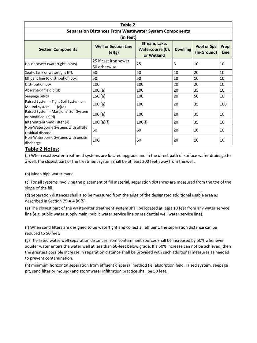
System ComponentsWell or Suction Line
(e)(g)
Stream, Lake, Watercourse (b),
or WetlandDwelling
Pool or Spa (In-Ground)
Prop. Line
House sewer (watertight joints)25 if cast iron sewer 50 otherwise
25 3 10 10
Septic tank or watertight ETU 50 50 10 20 10Effluent line to distribution box 50 50 10 10 10Distribution box 100 100 20 20 10Absorption field(c)(d) 100 (a) 100 20 35 10Seepage pit(d) 150 (a) 100 20 50 10Raised System - Tight Soil System or Mound system (c)(d) 100 (a) 100 20 35 100
Raised System - Margional Soil System or Modified (c)(d) 100 (a) 100 20 35 10
Intermittent Sand Filter (d) 100 (a)(f) 100(f) 20 35 10Non-Waterborne Systems with offsite residual disposal 50 50 20 10 10
Non-Waterborne Systems with onsite discharge 100 50 20 10 10
Table 2 Notes:
(h) minimum horizontal separation from effluent dispersal method (ie. absorption field, raised system, seepage pit, sand filter or mound) and stormwater infiltration practice shall be 50 feet.
Table 2 Separation Distances From Wastewater System Components
(in feet)
(g) The listed water well separation distances from contaminant sources shall be increased by 50% whenever aquifer water enters the water well at less than 50-feet below grade. If a 50% increase can not be achieved, then the greatest possible increase in separation distance shall be provided with such additional measures as needed to prevent contamination.
(a) When wastewater treatment systems are located upgrade and in the direct path of surface water drainage to a well, the closest part of the treatment system shall be at least 200 feet away from the well.
(b) Mean high water mark.
(c) For all systems involving the placement of fill material, separation distances are measured from the toe of the slope of the fill.(d) Separation distances shall also be measured from the edge of the designated additional usable area as described in Section 75-A.4 (a)(5).(e) The closest part of the wastewater treatment system shall be located at least 10 feet from any water service line (e.g. public water supply main, public water service line or residential well water service line).
(f) When sand filters are designed to be watertight and collect all effluent, the separation distance can be reduced to 50 feet.

Number of BedroomsMinimum Tank Capacity
(gallons)
Minimum Liquid
Surface Area
(sq. ft.)
1,2,3 1,250 34
4 1,500 40
5 1,750 47
6 2,000 54
Table 3 Notes:
Table 3
Minimum Septic Tank Capacities
(a)Tank size requirements for more than six bedrooms shall be calculated by
adding 250 gallons and seven square feet of surface area for each additional
bedroom.
(b)Tank size requirements allow for the installation of garbage grinders.

220 260 300 330 390 450 440 520 600 550 650 750 660 780 900
1-5 92 108 125 138 162 187 184 216 250 230 270 312 275 325 374
6-7 110 130 150 165 195 225 220 260 300 275 325 375 330 390 450
8-10 123 145 167 184 217 250 245 290 333 306 360 417 367 433 500
11-15 138 162 188 207 244 281 275 325 375 344 406 469 413 488 563
16-20 158 186 214 236 279 321 315 372 429 393 464 536 472 557 643
21-30 184 217 250 275 325 375 367 433 500 459 542 625 550 650 750
31-45 220 260 300 330 390 450 440 520 600 550 650 750 660 780 900
Table 4 Notes:
2 Bedrooms 3 Bedrooms
(a) Dosing required if there is 500-feet or more of total trench length.
(b) Alternate Dosing required if there is 1000-feet or more of total trench length.
4 Bedrooms 5 Bedrooms 6 BedroomsPercolation
Rate
(min./inch)
Required Length of Absorption Trench (in feet)
Table 4
(Based Upon 2 ft. wide trench)Daily Flow Rate (gallons per day)

220 260 300 330 390 450 440 520 600 550 650 750 660 780 900
1-5 69 81 93.8 104 122 140 138 162 188 173 203 234 206 244 280.5
6-7 82.5 97.5 113 124 146 169 165 195 225 206 244 281 248 293 337.5
8-10 92.3 109 125 138 163 188 184 218 250 230 270 313 275 325 375
11-15 104 122 141 155 183 211 206 244 281 258 305 352 310 366 422.3
16-20 119 140 161 177 209 241 236 279 322 295 348 402 354 418 482.3
21-30 138 163 188 206 244 281 275 325 375 344 407 469 413 488 562.5
31-45 165 195 225 248 293 338 330 390 450 413 488 563 495 585 675
Table 4 Notes:(a) Dosing required if there is 500-feet or more of total trench length.
(b) Alternate Dosing required if there is 1000-feet or more of total trench length.
Table 4R
Required Length of Absorption Trench (in feet)
(For Gravelless products with allowable 25% REDUCTION)Daily Flow Rate (gallons per day)
Percolation
Rate
(min./inch)
2 Bedrooms 3 Bedrooms 4 Bedrooms 5 Bedrooms 6 Bedrooms

220 260 300 330 390 450 440 520 600 550 650 750 660 780 900
1-5 115 135 156 173 203 234 230 270 313 288 338 390 344 406 467.5
6-7 138 163 188 206 244 281 275 325 375 344 406 469 413 488 562.5
8-10 154 181 209 230 271 313 306 363 416 383 450 521 459 541 625
11-15 173 203 235 259 305 351 344 406 469 430 508 586 516 610 703.8
16-20 198 233 268 295 349 401 394 465 536 491 580 670 590 696 803.8
21-30 230 271 313 344 406 469 459 541 625 574 678 781 688 813 937.5
31-45 275 325 375 413 488 563 550 650 750 688 813 938 825 975 1125
Table 4 Notes:(a) Dosing required if there is 500-feet or more of total trench length.
(b) Alternate Dosing required if there is 1000-feet or more of total trench length.
Table 4A
Required Length of Absorption Trench (in feet)
(For Gravelless products with required 25% ADDITION)Daily Flow Rate (gallons per day)
Percolation
Rate
(min./inch)
2 Bedrooms 3 Bedrooms 4 Bedrooms 5 Bedrooms 6 Bedrooms

Percolation Rate
(min./inch)
Application Rate
(gal/day/sf)
1-5 1.20
6-7 1.00
8-10 0.90
11-15 0.80
16-20 0.70
21-30 0.60
31-45 0.50
Table 5 Notes:
Required Absorption Field Length = Required Area (sq ft) / 2 ft (trench width)
Table 5
Application Rates for Non-Standard Design Flows
Soil with a percolation of less than 1 min/in is unsuitable for a conventional system
Required Area (sq ft) = Flow Rate (GPD) / Application Rate (GPD/sq ft)

Manufacturer Product Model
Design Adjustment
Applied to Req'd
Overall Trench
Length
Reference
Design
Table
Allowed
for New
Install
Allowed
for Repair
or
Replacem
ent
Bio 2 Chamber 25% Addition 4A Yes Yes
Bio 3 Chamber 25% Reduction 4R Yes Yes
ARC 18 Chamber 25% Addition 4A Yes Yes
ARC 24 Chamber 25% Reduction 4R Yes Yes
ARC 36 Chamber 25% Reduction 4R Yes Yes
ARC 36 HC Chamber 25% Reduction 4R Yes Yes
ARC 36 HC H-20 Chamber 25% Reduction 4R Yes Yes
Standard Bio (34" wide) 25% Reduction 4R Yes Yes
BioDiffuser HC H-20 (34") 25% Reduction 4R Yes Yes
Contractor EZ-24 Chamber 25% Addition 4A Yes Yes
Contractor 100 Chamber 25% Reduction 4R Yes Yes
Equalizer 24 25% Addition 4A Yes Yes
Quick4 Equalizer 24 25% Addition 4A Yes Yes
Quick4 Equalizer 24 HD 25% Addition 4A Yes Yes
Quick4 Equalizer 36 25% Reduction 4R Yes Yes
Quick4 Plus Equalizer 36 LP 1:1 4 Yes Yes
Quick4 Standard 25% Reduction 4R Yes Yes
Quick4 Plus Standard 25% Reduction 4R Yes Yes
Quick4 Plus Standard LP 1:1 4 Yes Yes
High Capacity H-20 25% Reduction 4R Yes Yes
EZflow 1202H 1:1 4 No Yes
Enviro-Septic System 25% Reduction 4R No Yes
Advanced Enviro-Septic
Systemuse 6.0 ft2/LF rating N/A No Yes
Eljen Corporation
www.eljen.comGeotextile Sand Filter use 6.0 ft2/LF rating N/A No Yes
Table 6 Notes:
*This list shall be updated as new products are accepted. Check with MCDPH to see if new products have been
Advanced Drainage Systems
(ADS)
www.ads-pipe.com
Cultec
www.cultec.com
Infiltrator Systems
www.infiltratorsystems.com
Presby Environmental
www.presbyeco.com
*All systems subject to MCDPH approval prior to installation.
Table 6
Acceptable Gravelless Absorption Trench Products*
*New installations subject to compliance with section VIII.(c)
*The above list is not an endorsement of any of the products by MCDPH. This department does not "approve"
proprietary products. However, products are reviewed to determine their compliance with NYS Appendix 75-A and local
*Products shall be installed in accordance with the manufacturer's recommendations.

Percolation Rate
(min./inch)
Application Rate
(gal/day/sf)
1-5 0.95
6-7 0.80
8-10 0.70
11-15 0.60
16-20 0.55
21-30 0.45
> 30 Not Acceptable
Table 7
Absorption Beds - Application Rates for Req'd Bottom Area

220 260 300 330 390 450 440 520 600 550 650 750 660 780 900
1-5 1.20 183 217 250 275 325 375 367 433 500 458 542 625 550 650 750
6-7 1.00 220 260 300 330 390 450 440 520 600 550 650 750 660 780 900
8-10 0.90 244 289 333 367 433 500 489 578 667 611 722 833 733 867 1,000
11-15 0.80 275 325 375 413 488 563 550 650 750 688 813 938 825 975 1,125
16-20 0.70 314 371 429 471 557 643 629 743 857 786 929 1,071 943 1,114 1,286
21-30 0.60 367 433 500 550 650 750 733 867 1,000 917 1,083 1,250 1,100 1,300 1,500
31-45 0.50 440 520 600 660 780 900 880 1,040 1,200 1,100 1,300 1,500 1,320 1,560 1,800
Over 45
Daily Flow Rate (gallons per day)
Percolation
Rate
(min./inch)
Sewage
Application
Rate
(gpd/sq ft)
Unsuitable…Use Special Design
Table 8
Seepage Pits - Required Absorptive Area For Residential Systems (in square feet)
2 Bedrooms 3 Bedrooms 4 Bedrooms 5 Bedrooms 6 Bedrooms

1
Foot
2
Feet
3
Feet
4
Feet
5
Feet
6
Feet
7
Feet
8
Feet
9
Feet
10
Feet
3 9.4 19 28 38 47 57 66 75 85 94
4 12.6 25 38 50 63 75 88 101 113 126
5 15.7 31 47 63 79 94 110 126 141 157
6 18.8 38 57 75 94 113 123 151 170 188
7 22.0 44 66 88 110 132 154 176 198 220
8 25.1 50 75 101 126 151 176 201 226 251
9 28.3 57 85 113 141 170 198 226 254 283
10 31.4 63 94 126 157 188 220 251 283 314
11 34.6 69 104 138 173 207 242 276 311 346
12 37.7 75 113 151 188 226 264 302 339 377
Table 9Seepage Pits (Cylindrical) - Dimensions for Required Absorptive Area
(in square feet)
π = 3.14
Effective Strata Depth Below Flow Line (Below Inlet)Diameter of
Seepage Pit
(feet)
Absorptive Area for Cylinder = πDh
Absorptive Area for Rectangle = (2W + 2L)h
h = effective depth (Invert of inlet to bottom of seepage pit)
D = outside diameter in ft
W — outside width in ft.
L — outside length in ft.

OWTS DESIGN AND CONSTRUCTION STANDARDS 2015 VERSION MONROE COUNTY, NEW YORK
APPENDIX B FIGURES
Figure 1 Test Hole Figure 2 Septic Tank Figure 3 Outlet Baffle Figure 4 Distribution Box Figure 5 Drop Box Figure 6 Dosing Chamber with Pump Figure 7 Dosing Chamber with Siphon Figure 8 Standard Absorption Trench System – Separation Requirements Figure 9 Absorption Trench Figure 10 Deep Absorption Trench System Figure 11 Cut & Fill System – Impermeable Soils Figure 12 Cut & Fill System – Rapidly Permeable Soils Figure 13 Absorption Bed System Figure 14 Precast Seepage Pit Figure 15 Raised Fill System – Plan Figure 16 Raised Fill System – Sections Figure 17 Mound System – Plan Figure 18 Mound System – Section Figure 19 Mound System – Pipe Lateral Layout Figure 20 Sand Filter System Figure 21 Sand Filter System – Second Stage Figure 22 Sand Filter System – First Stage
BB


MEASURING STICK (LATH)
(see
not
e ab
ove)
2"
1"
VARIE
S NAILS
CROSS BOARD
Make certain bottom ofcross board rests onbottom of test hole
WATERLEVEL
SOIL PERCOLATION TESTSTANDARD MCDPH DETAIL
-Dig a hole about 12" in diameter -Depth for Conventional System = 18"-30" -Depth for Alternative System = 6"-12" -Depth for Deep Trench or Seepage Pit shall be as determined by site specific design-Scrape sides and remove loose soil from bottom-Install measuring stick-Presoak and saturate soil-Observe and record the time in minutes required for the water to drop from 6" to 5"-Repeat test at least 3 times until results for two consecutive tests are approximately equal
FIGURE 1N.T.S
6"5"
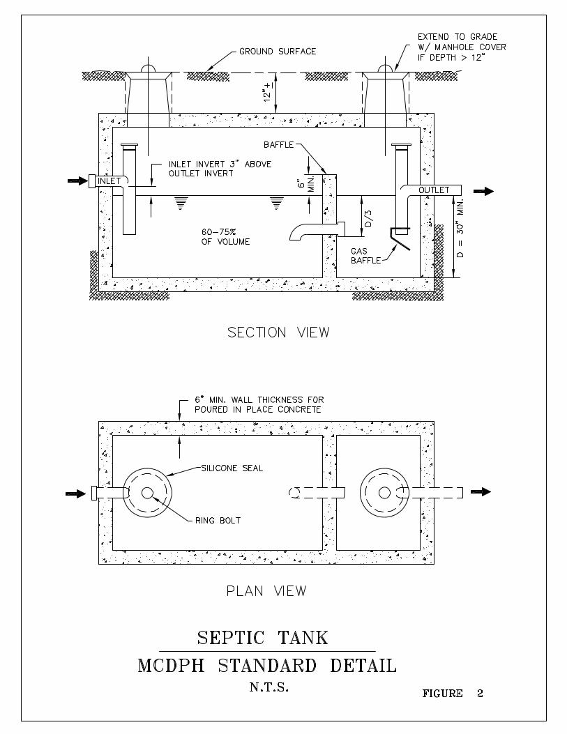


PLAN VIEW
ADJUSTABLE OUTLETLEVELERS
NON-PERFORATED PIPE WITHTIGHT JOINTS. SLOPE ≥1/32" FT.
PERFORATED PIPELENGTHS ≤60'-GRAVITY≤100'- DOSING
TRENCH WIDTH
FROM SEPTIC TANK, AEROBICUNIT OR DOSING TANK
Notes:1. Baffles at the inlet accomplished by means of tee or elbow as shown in figure 4.2. The inverts of all outlets to leach field in each manhole shall be at the same level.3. Maximize trench length along contour to minimize consecutive trenches.
12" MAX.
SLOPE
CENTER LINE SECTION VIEW
PERFORATED PIPELENGTHS ≤ 60'-GRAVITY≤ 100'- DOSING
LOCATION STAKES
BERM OR DITCH UPGRADETO DIVERT SURFACEDRAINAGE.
GRADE
REMOVABLE COVERS
2" MIN.
1-1/2" MIN. 12" MIN. SAND OR PEA GRAVEL 1-1/4" MIN.
DROP BOXSTANDARD MCDPH DETAIL
FIGURE 5N.T.S
(DO NOT INSTALL IF DOSING)


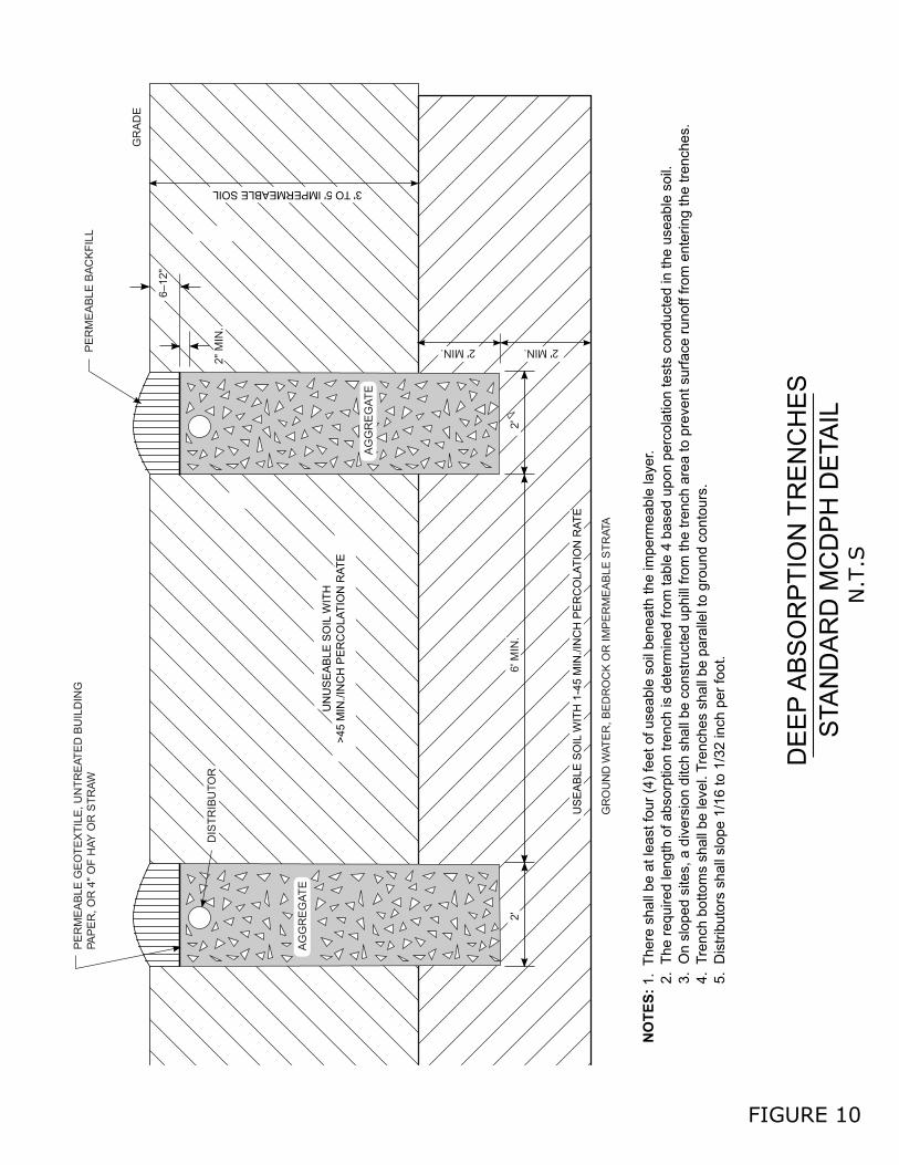
PE
RM
EA
BLE
GE
OT
EX
TIL
E, U
NT
RE
ATE
D B
UIL
DIN
GPA
PE
R, O
R 4
" O
F H
AY
OR
ST
RA
W
2'
DIS
TR
IBU
TO
R
6' M
IN.
GR
OU
ND
WAT
ER
, BE
DR
OC
K O
R IM
PE
RM
EA
BLE
ST
RAT
A
2'
2' MIN. 2' MIN.PE
RM
EA
BLE
BA
CK
FIL
L
GR
AD
E
2" M
IN.
6–12
"
3' TO 5' IMPERMEABLE SOIL
NOTES:
1. T
here
sha
ll be
at l
east
four
(4)
feet
of u
seab
le s
oil b
enea
th th
e im
perm
eabl
e la
yer.
2.
The
req
uire
d le
ngt
h of
abs
orpt
ion
tren
ch is
det
erm
ined
fro
m ta
ble
4 ba
sed
upo
n pe
rcol
atio
n te
sts
cond
ucte
d in
the
usea
ble
soil.
3.
On
slop
ed s
ites,
a d
iver
sion
ditc
h sh
all
be c
onst
ruct
ed u
phill
fro
m th
e tr
ench
are
a to
pre
vent
sur
face
run
off f
rom
ent
erin
g th
etr
ench
es.
4.
Tre
nch
bot
tom
s sh
all b
e le
vel.
Tre
nche
s sh
all b
e pa
ralle
l to
grou
nd c
onto
urs.
5.
Dis
trib
utor
s sh
all s
lope
1/1
6 to
1/3
2 in
ch p
er fo
ot.
US
EA
BLE
SO
IL W
ITH
1-4
5 M
IN./I
NC
H P
ER
CO
LAT
ION
RA
TE
UN
US
EA
BL
E S
OIL
WIT
H>
45 M
IN./I
NC
H P
ER
CO
LAT
ION
RA
TE
DE
EP
AB
SO
RP
TIO
N T
RE
NC
HE
S
STA
ND
AR
D M
CD
PH
DE
TAIL
N.T
.S
FIGURE 10
AG
GR
EG
AT
E
AG
GR
EG
AT
E


DB
GRADE
1.5' 3'
SAND MEDIA
DISTRIBUTOR
COLLECTOR
IMP
ER
ME
AB
LE S
OIL
>12
0/M
IN/IN
CH
PE
RC
OLA
TIO
N R
ATE
GRADE
6" - 12"≥
≥2"
≥24"
3"
4" PIPE≥4"
≥2"
≥24"
NOTES:1. A Single Center Collector may be used when the filter width does not exceed 12 Feet.2. Collector lines to be centered between distributor lines.3. Gravity distribution may be used to apply effluent to small filters having less than 300 LF of distributor or less than 900 SF of filter area.
LINER (RECOMMENDED)
EGS WITH NITRIFICATION 0.25 - 1.0 mmEGS WITHOUT NITRIFICATION 0.5 - 1.0 mmUC 4.0, ALL SAND SHALL PASS A 1/4 INCH SIEVE
3/4" - 1-1/2" AGGREGATE
1/8" - 1/4" CRUSHED STONE OR CLEAN GRAVEL
12' MAX.
2"
CROSS SECTION VIEW
PLAN VIEW
HIGH GROUNDWATER
EGS= EFFECTIVE GRAIN SIZE
3' MIN.6' MAX.
6' MIN.
OUTLET TO SECOND STAGE RAISED SYSTEM
INLET FROM SEPTIC TANKS HAVING DUAL COMPARTMENTS OR TWO TANKS IN SERIES
OPTIONALCLEANOUT/VENT
M.H.
OPTIONAL LINER
SANDFILTERAREA
END CAPS
GR
AV
ITY
- 4
" P
ER
FO
RA
TE
D D
IST
RIB
UT
OR
PIP
E
4" P
ER
FO
RA
TE
D C
OLL
EC
TO
R P
IPE
SLO
PE
D 1
/16
TO
1/8
INC
H P
ER
FO
OT
GR
AV
ITY
- S
LOP
ED
1/1
6 T
O 1
/8 IN
CH
PE
R F
OO
T
CLAMP LINER AROUND PIPE
PE
RF
OR
AT
ED
DIS
TR
IBU
TO
R P
IPE
- L
EV
EL
PR
ES
SU
RE
DIS
TR
IBU
TIO
N S
YS
TE
M 1
" T
O 3
" D
IAM
ET
ER
SIP
HO
N O
R P
UM
P D
OS
ING
SY
ST
EM
3"
TO
4"
DIA
ME
TE
R
1" to 4" PIPE
8" UNIFORM LAYER
DOSING (SIPHON OR PUMP W/O DB)
≤
TOPSOIL
AGGREGATE
PERMEABLE GEOTEXTILEOR EQUIVALENT
DB = Distribution BoxDB not neededif pressure distribution.
UC = UNIFORMITY COEFFICIENT
SAND FILTER SYSTEM - 1ST STAGE STANDARD MCDPH DETAIL
FIGURE 22N.T.S