design and construction standards : plan submission guide : dbch · 2019-01-09 · standard notes...
TRANSCRIPT

September 1, 2016
Dutchess County
Design and Construction Standards
Plan Submission Guide for
Residential and Commercial Onsite Wastewater
Treatment Systems and Sewer Mains
for
Less Than 1,000 Gallons per Day

Page #2
TABLE OF CONTENTS
Foreword .................................................................................................................................................................... 4
Design and Construction Standards .......................................................................................................................... 5
Section 75-A.1 Introduction ............................................................................................................................... 6
Section 75-A.2 Regulation by Other Agencies .................................................................................................. 9
Section 75-A.3 Sewage Flows ......................................................................................................................... 10
Section 75-A.4 Soil and Site Appraisal ........................................................................................................... 14
Section 75-A.5 House Sewer ........................................................................................................................... 22
Section 75-A.6 Septic Tanks and Enhanced Treatment Units ......................................................................... 23
Section 75-A.7 Distribution Devices ............................................................................................................... 27
Section 75-A.8 Conventional Subsurface Treatment Systems ........................................................................ 30
Section 75-A.9 Alternative Subsurface Treatment Systems ............................................................................ 44
Section 75-A.10 Other Systems ....................................................................................................................... 51
Section 75-A.11 Specific Waivers ................................................................................................................... 53
APPENDIX .............................................................................................................................................................. 54
PERCOLATION TEST PROCEDURES ............................................................................................................ 55
Percolation test diagram ................................................................................................................................... 56
POLICY STATEMENT ON SUBMISSION OF ELECTRONIC COPIES OF PLANS .................................... 57
ENGINEERING PLAN PRE-SCREENING ....................................................................................................... 58
SUBMISSION STANDARDS GUIDE AND CHECKLIST .............................................................................. 59
INDIVIDUAL WELL APPROVAL & DETERMINING ADEQUACY OF WATER SUPPLY ...................... 70
ADDENDUM TO STANDARDS & GUIDELINES FOR INDIVIDUAL WELL APPROVAL ....................... 72
TEST WELL SAMPLING REQUIREMENTS ................................................................................................... 73
ENGINEERING REVIEW FEE SCHEDULE .................................................................................................... 76
FORMS TABLE .................................................................................................................................................. 77
MAP NOTES ....................................................................................................................................................... 78
Standard Notes for Projects w/Central Water & Sewer ................................................................................... 78
Standard Notes for Central Sewer Projects (No Water) ................................................................................... 80
Standard Notes for Commercial Projects (Onsite Water Source and Sewage Disposal) – W/No PWS .......... 81
Standard Notes for Commercial Projects (Onsite Water Source & Sewage Disposal) – W/PWS .................. 83
Standard Notes for Commercial Projects (Onsite Sewage Disposal & Central Water) ................................... 85
Standard Notes for Residential Projects (Onsite Water Source & Sewage Disposal) ..................................... 87
Standard Notes for Residential Projects (Onsite Sewage Disposal & Central Water) ..................................... 89
Standard Notes for Public Water Systems w/Distribution Improvements ....................................................... 91

Page #3
Standard Notes for Public Water Systems w/No Distribution Improvements ................................................. 92
Standard Notes for Projects w/Central Sewer & Onsite Water Source – W/PWS .......................................... 95
Standard Notes for PWS Well Location Plan .................................................................................................. 97
Standard Notes for Pools.................................................................................................................................. 98
Miscellaneous Notes ........................................................................................................................................ 99

Page #4
Foreword
The Dutchess County Sanitary Code gives the Dutchess County Department of Behavioral & Community Health
jurisdiction over onsite wastewater systems. The New York State Department of Health also has jurisdiction over
onsite wastewater systems. This Plan Submission Guide currently includes our Division of Environmental Health
Services’ adaptation of the New York State 10NYCRR Appendix 75-A “Wastewater Treatment Standards –
Individual Household Systems”. The New York State Health Department has also published a handbook in
support of Appendix 75-A, the “Residential Onsite Wastewater Treatment Systems Design Handbook”.
Appendix 75-A applies to systems handling residential wastewater less than 1,000 gallons per day (gpd). It is our
intention to also incorporate design/treatment standards for commercial type wastewater flows that are also less
than 1,000 gpd. Therefore, the New York State Department of Environmental Conservation’s “Design Standards
for Intermediate Sized Wastewater Treatment Systems” is also referred to in our Plan Submission Guide.
Our adaptation of Appendix 75-A has the title of “Module 1”. Modifications/additions are highlighted in bold
print. Much of the information in bold was done to incorporate historic Dutchess County Department of
Behavioral & Community Health policy that was not previously in our former “Design and Construction
Standards”. New to our “Module 1” is the allowed design flow reduction from the current 130 gpd/bedroom to
the revised 110 gpd/bedroom. This reduction is based on observed national trends of water conservation. Our
Plan Submission Guide is intended to serve as a one stop document to help educate, simplify and therefore
expedite the property improvement process. It is the goal of these documents to promote effective design,
construction, and maintenance of onsite wastewater treatment systems by design professionals, builders,
community officials, Dutchess County Department of Behavioral & Community Health officials and
homeowners.

Page #5
Design and Construction Standards
Also known as “Subsurface Sewage Treatment for Less Than One Thousand Gallons Per Day Flows”
September 1, 2016
Page #6
Section 75-A.1 Introduction
(a) This appendix applies to on-site wastewater treatment systems serving residential properties and receiving
sewage without the admixture of industrial wastes or other wastes, as defined in Environmental
Conservation Law, Section 17-0701, in quantities of less than 1,000 gallons per day (gpd).
Dutchess County Environmental Health Services Division (DC EHSD) Note: Section 75-A.1(a) is
accepted as policy and standard, except as the following:
DC1. On-site wastewater treatment systems (OWTS) and sewer mains for projects with a design
flow less than 1,000 gallons per day shall be designed in accordance with this policy and
standard which includes the requirements of 10NYCRR Appendix 75-A, Wastewater
Treatment Standards – Residential On-site Systems. Additional requirements by the DC
EHSD are noted in bold font.
DC2. Standards and Guidelines also include those specifically set forth by the Dutchess County
Sanitary Code and the New York State Department of Health Environmental Health Manual.
Additional guidance is available in the New York State Department of Health Residential On-
site Wastewater Treatment Systems Design Handbook and the New York State Design
Standards for Intermediate Sized Wastewater Treatment Systems.
DC3. The DC EHSD has plan review and approval authority for projects involving the
construction or modification of all OWTS, wells, water mains, sewer mains, grease traps,
pump stations, wastewater treatment facilities, public water systems and public swimming
pools. Projects located within the New York City Department of Environmental Protection
(NYCDEP) watershed are in addition subject to the approval of that agency.
DC4. When sufficient supply and capacity exists in the existing infrastructure, DC EHSD may
accept approval of direct service connections as defined by DC EHSD in section 75-A.1(b)
from the owning entity of the sewage collection or water distribution infrastructure.
DC5. All engineered plan submissions to this Department shall be accompanied by the
appropriate review fee, application, and proof of preliminary approval by the local
municipality where applicable, a short environmental assessment form or proof of State
Environmental Quality Review Act (SEQR) determination by the lead agency and an
engineer’s report with supporting calculations and specifications.
DC6. Site plans shall show all rock outcrops, large boulders, wetlands, streams, drainage swales,
flood zones, easements, embankments, right of ways, filled areas, existing and proposed
driveways, stormwater infrastructure, wells, pipes, OWTS components, and grading
(existing and proposed) located in the proximity of the proposed infrastructure such that
potential impacts can be evaluated.
DC7. The design basis shall be clearly explained on the plans. For small residential projects the
design basis is the number of bedrooms, the per bedroom flow, and any softener, garbage
grinder or other fixture/treatment flow. Small residential plans shall clearly designate the
maximum number of bedrooms for which the property is designed. Commercial projects
design basis must include the daily flows and the derivation of those flows.
DC8. All components of the OWTS must be delineated and specified on the plans. The area and
design shown must represent the largest flow indicated including its required replacement
OWTS.
DC9. Erosion control measures shall be specified via notes and/or details for well and OWTS
installation.
DC10. Projects involving multiple approvals may be submitted separately for review for approval
and may require concurrent approval(s).

Page #7
DC11. The DC EHSD will not recommend the issuance of building permits until plans by a design
professional have been approved. Examples include new construction, reconstruction, and
expansion of existing structures.
DC12. Following the expiration of a Dutchess County Department of Behavioral &
Community Health approval, a request for extension of approval may be submitted to this
Department for review via a form prescribed by this Department. For projects which were
approved without an expiration date, requests for an evaluation of the previously approved
plans to substantiate recommending the issuance of a building permit must be submitted to
this Department via the same form. Processing involves evaluating the previously approved
design for compliance with current policy and standards that may affect the previously
approved system.
DC13. The DC EHSD will not recommend the issuance of certificates of occupancy, until it has
been demonstrated that the sewer and/or water infrastructure has been installed in
accordance with approved plans. For commercial projects, a design professional’s
completed works certification shall be required.
(b) Definitions - As used in this Appendix, the following words and terms shall have the indicated meaning:
DC EHSD Note: Section 75-A.1(b) is accepted as policy and standard. Additional definitions have
been noted in bold.
(1) Absorption Area - an area to which wastewater is distributed for infiltration to the soil.
(2) Absorption Field – the area to which sewage is distributed for infiltration to the soil be means of a
network of pipes.
(3) Absorption Trench - a long narrow area which includes a pipe for the distribution of septic tank
effluent.
(4) Aerobic Treatment Unit - a system that provides for the biological decomposition of the organic
portion of the wastewater by mechanical aeration of the wastewater.
(5) Aggregate - washed gravel or crushed stone ¾ inch to 1½ inches diameter.
(6) Application Rate - the rate at which septic tank effluent is applied to a subsurface absorption area, for
design purposes, expressed in gallons per day per square foot
(7) Baffle - a flow deflecting device used in septic tanks and distribution boxes to inhibit the discharge of
floating solids, reduce the amount of settleable solids that exit, and reduce the exit velocity of the
wastewater.
(8) Building Sewer - that part of the drainage system which extends from the end of the building drain
and conveys wastewater to the sewage system or sewer.
(9) Cleanout - an opening providing access to part of the sewage system.
(10) Commissioner - the State Commissioner of Health.
(11) Curtain Drain - a subsurface drain designed and constructed to control groundwater and surface
water intrusion into the area of the sewage system.
(12) Design professional - a person licensed or registered in the State of New York and authorized by
the State Education Law to design the systems described in the standards.
DC14. Direct Service Connection – A pipe connection from a single building in a water or sewer
district to an existing water distribution pipe or an existing sewer collection pipe owned or
controlled by that water/sewer district which consists solely of pipe. The sewage must be
conveyed by gravity. The direct service connection must be contained on the building
property or on property controlled by the water/sewer district.

Page #8
(13) Distribution Device - a device used to uniformly distribute sewage to the absorption area.
(14) Distribution Line - the perforated pipe used to distribute wastewater to the absorption area.
(15) Drinking Water - water whose physical, chemical and biological quality is or is intended to be
satisfactory for human consumption, food preparation or culinary purposes.
(16) Effective Grain Size - a measure of the diameter of soil particles, when compared to a theoretical
material having an equal transmission constant. It is the dimensions of that mesh screen which will
permit 10 percent of the sample to pass and will retain 90 percent.
(17) Enhanced Treatment: The biological and physical treatment of wastewater to reduce the amount of
biochemical oxygen demand (BOD) and total suspended solids (TSS) of wastewater effluent prior
to distribution to an absorption area.
(18) Enhanced Treatment Unit (ETU) – Pre-manufactured structures that provide enhanced treatment of
wastewater prior to discharge to a subsurface soil absorption area.
(19) Gas Baffle - a device on the outlet of a septic tank which deflects gas bubbles away from the outlet
and reduces the carryover of solid particles from the septic tank.
(20) Groundwater - subsurface water occupying the saturation zone from which wells and springs are
fed.
(21) Heavy Equipment - all equipment which would result in the compaction of the design absorption
area at a depth equivalent to the design depth of the distribution lines.
(22) Infiltration - the flow or movement of water into the interstices or pores of a soil through the soil
interface.
(23) Invert - the floor, bottom, or lowest point of the inside cross section of a pipe.
(24) Local Health Department - a city, county, or part-county department of health or a State
Department of Health District Office.
(25) Percolation - the movement of water through the pores of a soil or other porous medium following
infiltration through the soil interface.
(26) Permeability - a measure of the rate of movement of liquid through soil.
(27) Responsible Management Entity (RME) – A legal entity with the requisite managerial, financial
and technical capacity to ensure long-term management of residential wastewater treatment
systems. RMEs may include: sewer districts, utilities, municipal authorities or other entities with
the authority to enforce and the capacity to finance the long-term operation and maintenance
requirements necessary to ensure residential wastewater treatment systems are functioning
properly.
(28) Scum - the wastewater material which is less dense than water and floats on top of the water.
(29) Sewage - the combination of human and household waste with water which is discharged to the
home plumbing system including the waste from a flush toilet, bath, sink, lavatory, dishwashing or
laundry machine, or the water-carried waste from any other fixture, equipment or machine.
(30) Stabilized Rate of Percolation - the rate corresponding to two consecutive equal or near equal
percolation test results.
(31) Tire Derived Aggregate (TDA) - Aggregate manufactured from waste tires to a similar size
distribution as conventional gravel or stone aggregate and used as alternative to gravel or stone
aggregate in soil absorption areas.
(32) Useable Soil - unless otherwise stated a soil with a percolation rate from one (1) to sixty (60) min/in
with a compatible soil classification.
(33) Wastewater - any water discharged from a house through a plumbing fixture to include, but not
limited to, sewage and any water or waste from a device (e.g., water softener brine) which is
produced in the house or property.
Page #9
(34) Watercourse - a visible path through which surface water travels on a regular basis. Drainage areas
which contain water only during and immediately after a rainstorm shall not be considered a
watercourse.
(35) Watershed - an area of drainage for a body of water that serves as a source of drinking water and
for which watershed rules and regulations have been adopted by the commissioner.
(36) Well Head Area - the area surrounding a well which includes the cone of influence (where the
drawdown of groundwater causes groundwater flow).
(37) Wetland - an area(s) of marshes or swamps which have been designated as such by the State
Department of Environmental Conservation or other agency having jurisdiction. Marshes or
swamps that have not been classified by an agency as a wetland shall not be treated for design
purposes as a wetland.
Section 75-A.2 Regulation by Other Agencies
DC EHSD Note: Section 75-A.2 is accepted as policy and standard, except as follows:
DC15. Approval by the DC EHSD may be contingent upon receipt of proof of acceptance from
other agencies.
(a) Where sewage treatment systems are to be located on the watersheds or well head area of public
water supplies, the rules and regulations enacted by the State Department of Health for the protection
of these supplies must be observed. Where systems are to be located on the watershed of any stream
or body of water from which the City of New York obtains its water supply, the approval of the New
York City Department of Environmental Protection, Division of Water Resources, must also be
obtained.
(b) This appendix establishes the minimum standards acceptable in New York State. Other agencies, such
as the Adirondack Park Agency or local health departments may establish more stringent standards.
Where such standards have been established, or approval by another agency is required, the more
stringent standard shall apply.
(c) A local health department may not adopt standards less stringent than the State standard unless a
General Waiver has been issued by the State Commissioner of Health or his designated representative
as provided in Part 75 of this Title, or the local health department are otherwise legally authorized to
adopt such standards.
(d) When individual sewage systems overlay a drinking water aquifer, local health departments may
establish population density limits and minimum lot sizes for residential development with on-site
sewage treatment systems.

Page #10
Section 75-A.3 Sewage Flows
(a) Roof, footing, garage, cellar and surface water drainage must be excluded from the system. Water
softener, water recharge and backwash wastes normally are not to be discharged to the system unless a
separate subsurface discharge to an area 250 feet from wells or water courses is unavailable.
DC EHSD Note: Section 75-A.3(a) is accepted as policy and standard.
(b) Designs for new construction shall be based upon a minimum daily flow of 110 gallons per day per
bedroom. Other design flows listed in Table 1 may be applicable for systems receiving wastewater from
dwellings equipped with older plumbing fixtures or waterless toilets.
DC EHSD Note: Section 75-A.3(b) is accepted as policy and standard, except as follows:
DC16. Table 1A and the following additional policy have been added to address sewage flows for
commercial projects. The typical per unit hydraulic loading rates listed in Table 1A shall be
used for design flows associated with other uses not included in Table 1. Except for the
110/130/150 gallons per day per unit values, the per-unit hydraulic loading rates in Table
1A may be reduced by 20 percent for establishments equipped with water saving plumbing
fixtures. Table 1A was obtained from the New York State Design Standards for
Intermediate Sized Wastewater Treatment Systems.
DC17. For non-residential uses measured water or wastewater flow data may be used for the
purpose of determining the design flow when sufficient data is available. A minimum of six
months of data collected during similar operational conditions is required. When using this
method, the design professional must consider the average daily flow rate as well as the
maximum daily flow rate. The analysis must account for operational variations (e.g. peak
seasons, weekends, special events, peak use, etc.) and exclude extraneous data. The average
of the daily 24 hour flow over the duration of the data collection period is an acceptable
method for determining the average daily flow rate. The largest daily (24 hour) measured
volume during the same period expressed in volume per unit time is one acceptable method
for determining the maximum day flow rate. It is required that OWTS be designed based
on an accepted maximum daily flow.
DC18. OWTS and water system evaluations of existing facilities associated with expansion or use
changes must be submitted by a design professional to the DC EHSD engineer for approval.
The need for engaging the services of a design professional may be waived for sites where
there is an approved OWTS and water supply system, where a site plan approval is not
required, where measured water or wastewater flow data and/or the design flows in Tables
1 or 1A are used by the applicant to demonstrate that the existing infrastructure is suitably
sized for the proposed use and where there is no history of sewage failure or water
quality/quantity issues.
DC19. Existing OWTS capacity may be evaluated based on design standards applicable at the time
of approval however OWTS modifications will be evaluated for compliance with current
policy and standard.
DC20. The project design flow shall be specified on the plans.
DC21. All projects with the exception of single family homes served by their own well shall require
a water meter for the purpose of collecting flow data.

Page #11
Table 1
Daily Design Flows
Plumbing Fixtures
(based on manufactured date)
Minimum Design Flow
(gallons per day per bedroom)
Post-1994 Fixtures
1.6 gallons/flush toilets
2.5 gallons/minute faucets & showerheads
110
Pre-1994 Fixtures
3.5 gallons/flush toilets
3.0 gallons/minute faucets & showerheads
130
Pre-1980 Fixtures
3.5+ gallons/flush toilets
3.0+ gallons/minute faucets & showerheads
150
Waterless Toilets (e.g., composter)
(graywater discharge only) 75 (Not Acceptable)
Table 1A
Typical Per-Unit Hydraulic Loading Rates (Gallons per Day)
Residential
Apartment Per Bedroom 110/130/15016
Mobile Home Park “Single-Wide” Home 220
“Double-Wide” Home 330
Single Family Residence Per Bedroom 110/130/150
Campgrounds
Day Camp
Per Person 15
Add for Lunch 5
Add for Shower 5
Campground
Per Unsewered Site18
55 (includes
showers)
Per Sewered Site – with water hookups 100
Per Sewered Site – without water hookups 55
Campground Day Use Per Person 5
Dumping Station 19
Per Unsewered Site 10
Per Sewered Site 5
Institutional
Assisted Living Facility/Complex Per Bed
20,21 –
add 10 gpd for in room kitchen 110/130/150
Group Home (residential-style
building) 26, 27
Per Bed20
–
add 150 gpd per house for garbage grinder 110/130/150
Nursing Home (hospital care) Per Bed20,21
175
Hospital Per Bed
20,21 175
Per Outpatient 30
Church Per Seat20
3
Church Hall/Fire Hall Per Seat21
10
Library/ Museum Per Patron20,21
5
Public Park Per Person (toilet only) 5
Prison / Jail Per Inmate20,21
150

Page #12
School – Day Per Student 10
- or - Elem./ Jr. High / Sr. High 7 / 9 / 12
- and - Add for meals / showers 5 / 5
School Boarding Per Student20,21
75
Commercial
Airport/Bus/Rail Terminal Per Passenger
22
Per Toilet
5
400
Barber Shop / Beauty Salon Per Station without and with hair care sink 50/
200
Bowling Alley Per Lane 22,23
75
Bed & Breakfast Per Room 110/130/150
Casino Per Employee/shift plus
Per Sq. Ft. for non-lodging customer use
15
0.3
Country Clubs & Golf Courses
Per Round of Golf 21,22
(add for bar, banquet, shower or pool
facilities and golf tournaments)
20
Concert Hall / Arena / Assembly Hall
/ Theater / Stadium / Skating Rink Per Seat
21,22 5
Day Care Per Child 21
20
Doctors Office Per Doctor 250
Dog / Pet Grooming
Also see Kennel and Veterinary
Office below.
Per Station 500
Dentist Per Chair24
250
Drive-In Theater Per Car Space 25
5
Factory / Distribution Warehouse Per Employee/shift;
add for showers
15
10
Fairgrounds Per Visitor 25
5
Health Club Per Patron 20
Highway Rest Area Per Traveler
25
Per Dump Station Vehicle
5
7
Hotel
Per Sleeping Unit 25
add for banquet hall, night club, pool/spa,
theatre, etc.
110/130/150
Kennel Per Kennel/Run/Cage 50
Laundromat Per Machine 580
Marina
Per Slip 25
with shore side restroom facilities including
shower
20
add per slip for dump station 7
Migrant Worker Housing Per Person 50
Motel
Per Sleeping Unit; 110/130/150
add for in-room kitchen; 10
add for in-room jacuzzi/spa 20
Office Building Per Employee
25; 15
add for showers 5
Service station/Convenience store Per Toilet25
400
Shopping Center / Grocery Store /
Department Store
Per Sq. Ft. 25,26
;
add for deli, bakery, butcher 0.1

Page #13
Swimming Pool /
Bath House Per Swimmer 10
Veterinary Office Per Veterinarian 200
Food Service Operations 27
Ordinary Restaurant Per Seat 35
24-Hour Restaurant Per Seat (for cafeterias: pro rate flow in
proportion to the hours) 50
Fast Food Restaurant Per Seat 25
Per Drive-Up Window 500
Lounge, Bar Per Seat 20
Drive-In Per Car Space 50
Banquet Hall Per Seat 10
Restaurant along Freeway Per Seat 75
Table 1A notes:
16. 110 gallons per day for post 1994 plumbing code fixtures; 130 gallons per day for pre 1994
fixtures; and 150 gallons per day for pre 1980 fixtures. 18. Additional wastewater flow due to food service or laundry shall be accounted for. Structures
available for overnight occupancy other than those meeting the definition of a camping unit shall
be based on 150 gallons per day / unit for design flow purposes, pursuant to NYSDOH – Chapter
1 State Sanitary Code Subpart 7-3 Campgrounds. 19. The addition of flow for dump station sewage may be prorated by using an estimated percentage
of sites suited for RV use based on historical data. No reduction for low flow fixture usage
should be applied here. 20. Add 15 gallons per day per employee 21. Add for Food Service (e.g. 24-hour restaurant; refer to Food Service Operations Table) 22. Add 15 gallons per day per employee/shift 23. Add for Food Service (e.g. 24 hour restaurant; refer to Food Service Operations Table) 24. Dental offices must recycle mercury amalgam instead of washing it down the drain. NYSDEC’s
website has guidance referencing the 2002 law. 25. Add for Food Service (e.g. 24-hour restaurant; refer to Food Service Operations Table) 26. Add 15 gallons per day per employee/shift. 27. Garbage grinder use should be evaluated in the design phase of the project and accounted
for in tank and absorption area sizing.

Page #14
Section 75-A.4 Soil and Site Appraisal
(a) Site Investigation.
(1) Areas lower than the 10 year flood level are unacceptable for on-site systems. Slopes greater than 15
percent are also unacceptable.
DC EHSD Note: Section 75-A.4(a)(1) is accepted as policy and standard, except as follows:
DC22. The 10 year flood level does not require predictive analysis. Determination shall be by
visual observation, historical fact and professional judgment. In any event, the 10 year
flood level determination shall be jointly agreed upon by the design professional and the DC
EHSD review engineer prior to the submission of plans.
DC23. Sewage systems and wells are not permitted within the 100 year flood level. Area for
placement of the OWTS or well may be raised within the 100 year flood level area unless a
floodway area is designated therein. Any filling shall be subject to the approval of the local
municipality.
(2) There must be at least four feet of useable soil available above rock, unsuitable soil, and high seasonal
groundwater for the installation of a conventional absorption field system.
DC EHSD Note: Section 75-A.4(a)(2) is superseded as follows:
DC24. Type I conventional fill system:
For sites where rock or unsuitable soil is less than 6½ feet and high seasonal groundwater is less
than 5½ feet, but in either case no less than 2 feet and where a satisfactory percolation rate can be
run at 24 inches in natural soil, the lot may be improved with fill material in accordance with the
following conditions (reference is made to the type I fill section detail):
dc a) Deep tests and percolation tests shall be conducted in the natural soil.
dc b) Plan submission for lots proposed to be improved with fill shall include but not be limited
to the results of soil tests conducted in the natural soil, existing and proposed 2 feet
elevation contours in the area of the proposed house, well, primary and replacement
OWTS, minimum fill depth requirement, fill section detail and map notes for fill sections.
dc c) Replacement OWTS shall be sufficiently separated from the primary OWTS such that
impervious fill from the primary OWTS does not interfere with the replacement OWTS
design. Alternately the plans must specify that the fill for the replacement OWTS must be
installed at the time of installation of the primary OWTS fill.
dc d) Fill shall consist of sand and gravel fill. The sand and gravel fill must extend 3 feet beyond
the center of the trench. After the sand and gravel fill, there must be 7 feet of additional
soil, with the final 2 feet being impervious soil with a one vertical to three horizontal slope.
The toe of the slope shall extend into the virgin soil 6 to 12 inches deep and 24 inches wide.
Topsoil and grass seed shall be applied over the fill per the approved plan.
dc e) The percolation rate of the sand and gravel fill shall be equivalent to or less than the
percolation rate of the natural soil and shall be no more than 15 minutes per inch stabilized
rate. The design application rate shall be based on the percolation rate of the natural soil.
The design application rate of the fill shall be used where the percolation rate of the fill is
greater than the percolation rate of the natural soil.
dc f) Prior to the placement of the fill, the area of the OWTS shall be cleared of debris, and all
brush, trees, or other vegetation cut to the level of the virgin ground. No topsoil shall be
removed unless specifically indicated on the plans.

Page #15
dc g) The sand and gravel fill shall be mechanically compacted in 6 inch layers in a manner
which will allow adequate percolation throughout the fill, or be allowed to settle and
stabilize for a period of at least 6 months to include one freeze-thaw cycle.
dc h) For lots proposed to be improved with fill other than sand and gravel fill, fill shall be a
gravelly loam (gravel, sand, silt, and clay mixture). OWTS shall be sized based on the
percolation rate of the fill or natural soil, whichever is greater, and the fill shall be allowed
to settle and stabilize for a period of at least six months to include one freeze-thaw cycle.
dc i) Deep tests and percolation tests shall be required in the fill after settling and stabilization,
(or compaction, if sand and gravel is used.)
dc j) The fill, including location, material and dimension, must be in place and certified to DC
EHSD by a design professional as being suitable for the installation of the OWTS. The
design professional shall certify in writing that the fill material is in the proper location, of
the proper quantity and dimensions, and of proper quality. Proper quality must be
demonstrated by stabilized percolation tests, the results of which shall be submitted with
the engineer’s certification.
dc k) The type I fill section detail is provided for illustration purposes. If other than
conventional absorption trenches are proposed, the detail shall be customized accordingly.
Type I fill section detail:
DC25. Type II lot improvement:
Sites where the 24 inch to 30 inch percolation test exceeds 60 minutes per inch or where valid tests
cannot be performed in natural soil due to the presence of rock, groundwater, impervious strata or
other circumstances are not considered suitable "as is" for OWTS. However, the lot may be
improved for a subsurface system in accordance with the following conditions (reference is made
to the type II fill section detail):
dc l) By filing with DC EHSD a grading plan prepared by a design professional to include, but
not be limited to, the results of soil tests conducted in the natural soil, existing and
proposed 2 feet elevation contours in the area of the proposed house, well, primary and
replacement OWTS, minimum fill depth requirement, fill section detail and map notes for
fill sections. The grading plan must show that the fill will not create any drainage
problems, including any with adjacent parcels. The grading plan is to be submitted to the
DC EHSD and to the local municipality for review and acceptance prior to the fill being
placed.
3 feet 5 feet Top soil
Sand and
gravel fill Unspecified fill
clay
Original Grade
3
1
2 feet
Absorption
trench
4 feet to highest groundwater
5 feet to highest impermeable layer
5 feet to rock/impervious

Page #16
dc m) The fill material must be of a sufficient depth to allow installation of OWTS meeting the
applicable standards regarding depth to groundwater, rock and unsuitable soil without the
placement of additional fill material.
dc n) The stabilized fill material shall extend a minimum of 50 feet, or more if required by the
DC EHSD, beyond the proposed primary and reserve areas for the OWTS with a
minimum of a one (v) on four (h) slope, starting 25 feet from the proposed location of the
OWTS areas.
dc o) By filling and grading the lot after approval of the lot improvement grading plan, with soil
containing sand and gravel or a mixture of gravelly loam (gravel, sand, silt, clay mixture)
and topsoil (containing humus), seeding and allowing to settle and stabilize for a period of
at least 6 months and to include one freeze-thaw cycle. Fill shall include the replacement
OWTS.
dc p) After settling and stabilization, deep tests and percolation tests shall be required for design.
The design application rate shall be based on the percolation rate of the fill after settling
and stabilization.
dc q) Plans shall include, but are not limited to, the results of soil tests conducted in the fill, two
(2) foot elevation contours of the fill in the area of the proposed house, well, primary and
replacement OWTS and be submitted in accordance with standard requirements for
approval.
dc r) The design professional shall certify on the plans that the fill material was of an acceptable
quality and quantity, was in place and stabilized for a minimum of six (6) months to
include one freeze thaw cycle and suitable for placement of an OWTS.
dc s) The type II fill section detail is provided for illustration purposes. If other than
conventional absorption trenches are proposed, the detail shall be customized accordingly.
Type II lot improvement detail:
(3) Soils with very rapid percolation rates (faster than one minute per inch) are not suitable for subsurface
absorption systems unless the site is modified by blending with a less permeable soil to reduce the
infiltration rate throughout the area to be used.
DC EHSD Note: Section 75-A.4(a)(3) is accepted as policy and standard, except as follows:
DC26. Excavation and installation shall be certified by a design professional. Certification shall
include percolation test results for the blended soil.
(4) Subsurface treatment systems and components of the sewage system shall be separated from buildings,
property lines, waterbodies, utilities and wells, to maintain system performance, permit repairs and reduce
25 feet Top soil
Approved stabilized fill
Original Grade
4
1
25 feet
Absorption
trench
4 feet to highest groundwater
5 feet to highest impermeable layer
5 feet to rock/impervious

Page #17
undesirable effects of underground sewage flow and dispersion. Table 2 lists the acceptable minimum
separation distances from the various components of on-site wastewater treatment systems.
DC EHSD Note: Section 75-A.4(a)(4) is accepted as policy and standard.
(5) Once the required infiltration area is determined by daily flow, percolation tests and soil evaluation, the
required useable area of the property for subsurface treatment can be found. An additional useable area of
50 percent shall be set aside for future expansion or replacement whenever possible.
DC EHSD Note: Section 75-A.4(a)(5) is accepted as policy and standard, except as follows:
DC27. A 100 percent replacement OWTS shall be designed and shown.
DC28. The design criteria for the 100 percent replacement OWTS shall be included on the plans.
DC29. When an additional use is proposed on a property with an existing use without DC EHSD
approval or when it is proposed to subdivide a property with an existing use, at a minimum
a 100 percent replacement OWTS shall be designed for the existing use unless it can be
demonstrated that the existing OWTS is functioning satisfactorily and complies with current
standards. The exact location of the existing well and OWTS components shall be shown on
the site plan. A statement shall be included on the plan by the design professional indicating
that the existing OWTS serving the existing use is functioning satisfactorily with no apparent
discharge of sewage to the surface. In cases where the existing OWTS is found to be
unacceptable (cesspool, failing, too close to a well, stream, etc.) a primary and replacement
OWTS shall be designed for the existing use. The installation of the primary OWTS may be
required under certain circumstances.
DC30. When a trench length reduction is proposed based on the use of eligible open-bottom gravelless
chambers per Section 75-A.8(c)(3)(ii) or based on the use of an ETU per Section 75-A.6(b)(6),
the 100 percent replacement OWTS may also apply the trench length reduction.
DC31. The 100 percent replacement OWTS for gravelless geotextile sand filters shall be designed
using conventional absorption trench or open bottom gravelless chamber systems.
(b) Separation Requirements:
DC EHSD Note: Section 75-A.4(b) is accepted as policy and standard, except as follows:
DC32. Table 2 was revised to include additional separation requirements listed in the New York
State Design Standards for Intermediate Sized Wastewater Treatment Systems associated
with stormwater infrastructure, swimming pools and embankments.
DC33. Considerations regarding proper separation include factors such as OWTS design, OWTS
elevation, ground slope and ground water flow, well pumping rates, casing depth and
soil/rock condition or impervious barriers, etc. – conservative approaches should be
evaluated during design and are required to justify possible deviation from the separation
standards.
DC34. House sewer separation requirements shall be applicable to all raw sanitary sewer lines
including sewer mains.
DC35. All OWTS, service lines or wells must be located on the same property as the structures
served. No OWTS, service lines or wells shall be constructed on separate property or in an
easement.
DC36. A minimum 18 inch vertical separation shall be provided between the outside of the pipes
and appurtenances at crossings between water, sanitary sewer and storm sewer lines. One
full length of pipe shall be located so both joints will be as far as possible from the crossing.

Page #18
Special structural pipe supports may be required. Suction water lines shall never cross
under sanitary or storm sewer lines or any other OWTS components.
DC37. A minimum 10 foot horizontal separation shall be provided between the outside of the pipes
and appurtenances between water, sanitary sewer and storm sewer lines.
DC38. When it is not possible to obtain proper horizontal and vertical separation distances
between water, sanitary sewer and storm sewer lines, the following mitigative measures may
be considered on a case by case basis with justification by the design professional:
Sanitary or storm sewer shall be constructed of slip-on or mechanical joint pipe
complying with public water supply design standards and shall be pressure tested to 150
psi to assure water tightness.
The water line, sanitary sewer or storm sewer shall be encased in a watertight
carrier pipe or concrete encasement that extends a minimum of 10 feet on both sides of the
crossing and as far as the horizontal separation requirement is not met.

Page #19
Table 2
Separation Distances from Wastewater System Components (in feet)
System
Components
Well or
Suction Line (e)(g)
To Stream, Lake,
Watercourse (b), or Wetland
Dwelling Property
Line
Culvert (Tight
Pipe), Drainage
Ditch, Stormwater
Pipe, Rain Garden
Interceptor Drain/Open
Drainage Diversion to
Groundwater,
Stormwater Infiltration
Management Practice,
Culvert Openings and
Catch Basins
Stormwater
Management
Practice
Discharging to
Surface Water
Swimming
Pool
In-ground
Top of
Embankment/
retaining wall
or Very Steep
Slope
House sewer (watertight joints)
50 (h) 25 3 10 10 25 25 10 25
Septic tank or
watertight ETU 50 50 10 10 25 25 50 20 25
Effluent line to distribution box
50 50 10 10 10 25 25 10 25
Distribution box 100 100 20 10 35 50 100 35 50
Absorption
field(c)(d) 100 (a) 100 20 10 35 50 100 35 50
Seepage pit(d) 150 (a) 100 20 10 35 50 100 50 50
Raised or Mound
system (c)(d) 100 (a) 100 20 10 35 50 100 50 50
Intermittent Sand
Filter (d) 100 (a)(f) 100 (f) 20 10 35 50 100 50 50
Non-Waterborne Systems with offsite
residual disposal
50 50 20 10 35 25 50 20 25
Non-Waterborne
Systems with on-site discharge
100 50 20 10 35 50 100 35 50
Notes:
a. When wastewater treatment systems are located upgrade and in the direct path of water drainage to a well, the closest part of the treatment system shall be at least 200 feet away from the well.
b. Mean high water mark. This category shall include intermittent streams, vernal ponds and areas where surface water ponding occurs. c. For all systems involving the placement of fill material, separation distances are measured from the toe of the slope of the fill.
d. Separation distances shall also be measured from the edge of the designated additional usable area as described in Section 75-A.4 (a)(5).
e. The closest part of the wastewater treatment system shall be located at least 10 feet from any water service line (e.g. public water supply main, public water service line or residential well water service line).
f. When sand filters are designed to be watertight and collect all effluent, the separation distance can be reduced to 50 feet. g. The listed water well separation distances from contaminant sources shall be increased by 50% whenever aquifer water enters the water well at less than 50-feet below grade. If a 50% increase cannot be
achieved, then the greatest possible increase in separation distance shall be provided with such additional measures as needed to prevent contamination.
h. Cast iron is no longer acceptable.

Page #20
(c) Soil Investigation.
DC EHSD Note: Section 75-A(c) Soil investigations shall not be conducted during weather conditions
that may impede the test or the determination of site constraints.
(1) The highest groundwater level shall be determined and shall include the depth to the seasonal high
groundwater level and the type of water table -- perched, apparent, or artesian.
DC EHSD Note: Section 75-A.4(c)(1) is accepted as policy and standard, except as follows:
DC39. All re-grading or alterations or installation of curtain drains and drainage systems affecting
more than one contiguous lot shall be completed and the completion certified by a design
professional prior to final approval of the plan.
DC40. Any re-grading or alterations or installation of curtain drains and drainage systems affecting
more than one contiguous lot which affect the functionality of the OWTS and wells must be
maintainable.
DC41. The installation of curtain drains or other drainage systems proposed to lower the water table
in lieu of fill must be completed, its effectiveness demonstrated and the completion certified by
a design professional prior to final plan approval.
DC42. All other lot re-grading, alterations or drainage systems which are required as part of the plan
shall be completed and the completion certified by a design professional.
(2) If a subsurface treatment unit such as an absorption field is planned, at least four feet of useable soil
shall be available over impermeable deposits (i.e., clay or bedrock). Highest groundwater level shall
be at least two feet below the proposed trench bottom. Where systems are to be installed above
drinking water aquifers, a greater separation distance to bedrock may be required by the local health
department having jurisdiction. At least one test hole at least six feet deep shall be dug within or
immediately adjacent to the proposed leaching area to insure that uniform soil and site conditions
prevail. If observations reveal differing soil profiles, additional holes shall be dug and tested. These
additional holes shall be spaced to indicate whether there is a sufficient area of useable soil to install
the system. Treatment systems shall be designed to reflect the most severe conditions encountered. If
the percolation tests results are inconsistent with field determined soil conditions, additional
percolation tests must be conducted and the more restrictive tests must be the factor used for the
system design.
DC EHSD Note: Section 75-A.4(c)(2) is superseded as follows:
DC43. If an OWTS such as absorption field is planned, at least 5 feet of useable soil shall be available
over impermeable deposits (i.e. clay or bedrock) below bottom of trench. Highest groundwater
level shall be at least 4 feet below the proposed trench bottom. A minimum of two (2) deep test
holes, widely spaced within the proposed leaching areas, are required to insure that uniform
soil and site conditions prevail. The deep tests shall also be representative of the replacement
OWTS. If observations reveal differing soil profiles, then additional holes shall be dug for
observation. These additional holes shall be spaced to indicate whether there is a sufficient
area of useable soil to install the system. The OWTS shall be designed to reflect the most
severe conditions encountered. If the percolation test results are inconsistent with field
determined soil conditions, then additional percolation tests shall be conducted and the more
restrictive tests shall be the factor used for the system design.
DC44. The percolation (stabilized rate and depth) and deep tests (soil strata, depth, rock and water
depth) results shall be included on the plans. Percolation and deep tests shall be shown in
their exact location for each lot. The DC EHSD shall be notified prior to conducting the
deep tests so that they may be observed by a representative of DC EHSD. The results of
percolation and deep tests must accompany each submission and be certified as to accuracy
by the design professional.

Page #21
(3) Test holes for seepage pits shall extend to at least mid-depth and full depth of the proposed pit
bottom. At least three feet of useable soil shall exist between the pit bottom and rock or other
impermeable soil layer and the highest groundwater level. This shall be confirmed by extending at
least one deep test hole three feet below the deepest proposed pit.
DC EHSD Note: Section 75-A.4(c)(3) is accepted as policy and standard except as follows:
DC45. 5 feet of useable soil shall exist between the pit bottom and rock or impermeable soil layer
and 4 feet between the pit bottom and the highest groundwater level. This shall be
confirmed by extending the deep test holes to an appropriate depth.
(4) A local health department may accept or require other soil tests in lieu of the percolation test when
such tests are conducted or observed by local health department personnel.
DC EHSD Note: Section 75-A.4(c)(4) is accepted as policy and standard
(d) Soil Percolation Test.
DC EHSD Note: Section 75-A.4(d) is accepted as policy and standard except as follows:
DC46. Percolation tests shall not be conducted during weather conditions that may impede the test
or the determination of site constraints including rock outcrops and wet areas.
DC47. The percolation tests shall be widely placed within the proposed leaching area and be
representative of the replacement area. The engineer's report or plan shall certify that pre-
soaking was done in accordance with the DC EHSD policy and standard, "Percolation Test
Procedure".
DC48. Percolation tests for all OWTS’s shall reflect the soil at the bottom and mid-depth of the
unit.
(1) At least two percolation tests shall be made at the site of each proposed sewage treatment system.
(2) For seepage pits, one test shall be conducted at the bottom depth, and the other at half the pit depth. If
different soil layers are encountered when digging the test pit, a percolation test shall be performed in
each layer with the overall percolation rate being the weighted average of each test based upon the
depth of each layer. The local health department having jurisdiction may adopt an alternative
procedure for determining the permeability of soil for the installation of seepage pits.
(3) A percolation test is only an indicator of soil permeability and must be consistent with the soil
classification of the site as determined from the test holes.

Page #22
Section 75-A.5 House Sewer
DC EHSD Note: Section 75-A.5 is accepted as policy and standard, except as follows:
DC49. There shall be no bends in the raw sewer line.
DC50. A minimum raw sewer line invert elevation shall be shown for each lot.
DC51. A minimum 18 inch vertical separation and 10 foot horizontal separation shall be provided
between the outside of the pipes and appurtenances at crossings between water, sanitary
sewer and storm sewer lines.
(1) House sewers are laid on firm foundation at a minimum grade of one-quarter inch per foot preferably
without bends. At least one cleanout with a properly fitted plug is to be provided. The house sewer
shall allow for venting of gases from the sewage system.
(2) House sewer construction including materials shall comply with the applicable requirements of the
State Uniform Fire Prevention and Building Code, Residential Code, Chapter 30, Sanitary Drainage.
(3) A minimum horizontal separation of 10 feet should exist between the house sewer and any water line.
Where lines must cross, the water service line shall be at least 12 inches above the house sewer. If a
water line must pass below the house sewer, the vertical separation must be at least 18 inches.
(4) Suction waterlines shall never cross under house sewers or any other component of the sewage
system.

Page #23
Section 75-A.6 Septic Tanks and Enhanced Treatment Units
(a) General information.
DC EHSD Note: Section 75-A.6(a) is accepted as policy and standard, except as follows:
DC52. Section D.6 of the New York State Design Standards for Intermediate Sized Wastewater
Treatment Systems is accepted as policy and standard for sizing commercial septic tanks.
DC53. Section D.5 of the New York State Design Standards for Intermediate Sized Wastewater
Treatment Systems is accepted as policy and standard for sizing of grease interceptors. All
facilities that have the potential to discharge fats, oils and grease (FOG) shall be required to
install a grease interceptor.
DC54. Objects and structures such as swimming pools, sheds or decks shall not be constructed
above septic tanks, grease traps or enhanced treatment units (ETU) since they may interfere
with septic tank, grease trap or ETU operation and maintenance.
DC55. Septic tanks, grease traps and ETUs installed under paved or traffic loading areas must be
designed to withstand the maximum anticipated loading and be accessible.
DC56. The installation of lockable and watertight manhole extension collars and covers shall be
required for commercial projects and where effluent filters are proposed.
DC57. Effluent filters shall be maintained by the property owner in accordance with manufacturer
recommendations/specifications.
DC58. Garbage grinders are not recommended for facilities served by OWTS.
(1) Septic tank capacities shall be based upon the number of household bedrooms. An expansion attic
shall be considered as an additional bedroom. Table 3 specifies minimum septic tank capacities and
minimum liquid surface areas.
Table 3
Minimum Septic Tank Capacities
Number of Bedrooms Minimum Tank
Capacity (Gallons)
Minimum Liquid
Surface Area (SQ. FT.)
1, 2, 3 1,000 27
4 1,250 34
5 1,500 40
6 1,750 47
NOTE: Tank size requirements for more than six bedrooms shall be calculated by adding 250 gallons and
seven square feet of surface area for each additional bedroom. A garbage grinder shall be considered
equivalent to an additional bedroom for determining tank size.
(2) Septic tank covers shall always be accessible. Where manholes are more than 12 inches below final
grade, an extension collar shall be provided over each opening. Extension collars shall not be brought
flush with the ground surface unless the cover can be locked to prevent tampering. Driveways or
other facilities shall not be constructed above septic tanks unless specially designed and reinforced to
safely carry the load imposed.

Page #24
(b) Design and Installation.
(1) General Requirements. The following applies to all septic tanks regardless of material.
DC EHSD Note: Section 75-A.6(b)(1) is accepted as policy and standard, except as follows:
DC59. Septic tank effluent lines are to be laid on a firm foundation at a minimum grade of 1/8 inch
per foot.
DC60. Septic tank effluent filters shall have a label indicating compliance with Nations Sanitation
Foundation (NSF) Standard 46 or equivalent.
DC61. Buoyancy calculations shall be provided in the engineer’s report for septic tanks, enhanced
treatment units and grease traps installed below the maximum groundwater table elevation.
DC62. If the tank is delivered to the site in sections, then it shall be demonstrated by the contractor
to the DC EHSD field inspector and/or design professional that the tank is sealed,
watertight and acceptable for use. This shall require, at a minimum, the filling of the tank
with water to observe if it is in fact sealed, watertight and acceptable for use. This shall be
made a condition of approval on the plans.
(i) A minimum liquid depth of 30 inches. The maximum depth for determining the allowable design
volume of a tank shall be 60 inches. Deeper tanks provide extra sludge storage, but no credit shall
be given toward design volume.
(ii) The minimum distance between the inlet and outlet shall be six feet. All tanks shall meet the
minimum surface area requirement for the specific design volume specified in Table 3. The
effective length of rectangular tanks should not be less than two nor greater than four times the
effective width.
(iii) Tanks must be watertight, constructed of durable material not subject to corrosion, decay, frost
damage, or cracking. After installation, all septic tanks shall be able to support at least 300
pounds per square foot (psf).
(iv) Tanks with a liquid depth of 48 inches or more shall have a top opening with a minimum of 20
inches in the shortest dimension to allow entry into the tank. Tanks with a liquid depth less than
48 inches shall have a top opening that is at least 12 inches in the shortest dimension.
(v) Tanks shall have inlet and outlet baffles, sanitary tees or other devices to prevent the passage of
floating solids and to minimize disturbance of settled sludge and floating scum by sewage
entering and leaving the tank. Outlet designs such as gas deflection baffles are strongly
recommended in all tanks. Inlet and outlet baffles shall extend a minimum of 12 inches and 14
inches respectively, below the liquid level in tanks with a liquid depth of less than 40 inches, and
16 and 18 inches respectively, in tanks with a liquid depth of 40 inches or greater. The distance
between the outlet baffle and the outlet shall not exceed six inches. Baffles shall be constructed of
a durable material not subject to corrosion, decay or cracking.
(vi) There shall be a minimum of one inch clearance between the underside of the top of the tank and
the top of all baffles, partition and/or tees to permit venting of tank gases. Multi-chamber and
multi-tank systems shall also be designed to permit the venting of tank gases.
(vii) Tanks shall be placed on at least a three inch bed of sand or pea gravel. This will provide for
proper leveling and bearing. Additional instructions provided by the manufacturer shall also be
followed.
(viii) There shall be a minimum drop in elevation of two inches between the inverts of the inlet and
outlet pipes.
(ix) Garbage grinders. An additional 250 gallons of capacity and seven square feet of surface area is
required when a garbage grinder can reasonably be expected at the time of construction or in the

Page #25
future. A gas deflection baffle or other acceptable outlet modification, and a dual compartment
tank or two tanks in series must also be provided.
(2) Multi-compartment tanks or tanks in series.
DC EHSD Note: Section 75-A.6(b)(2) is accepted as policy and standard, except as follows:
DC63. Tanks in series shall be connected by a single pipe with a minimum slope of one quarter inch
(¼") per foot.
(i) Dual compartments are recommended for all tanks and shall be required on all tanks with an
interior length of ten feet or more.
(ii) The first compartment or tank (inlet side) shall account for 60 - 75% of the required total design
volume.
(iii) The baffle separating the compartments shall extend from the bottom of the tank to at least six
inches above the invert of the outlet pipe.
(iv) Compartments shall be connected by a four inch vertical slot at least 18 inches in width, a six
inch elbow, or two 4-inch elbows located at a distance below the liquid level equal to one-third
the distance between the invert of the outlet and the bottom of the tank. At least one access
manhole shall be provided into each compartment.
(v) Tanks in series should be connected by a single pipe with a minimum diameter of four inches.
(vi) The volume and surface area for meeting the requirements of Table 3 shall be based upon the
total volume and surface areas of all the tanks and chambers.
(3) Concrete tanks.
DC EHSD Note: Section 75-A.6(b)(3) is accepted as policy and standard.
(i) Concrete shall have a minimum compressive strength of 2,500 pounds per square inch (psi) at 28
days set; 3,000 psi concrete is recommended as a minimum.
(ii) Wall thickness shall be a minimum of three inches unless the design has been certified by a New
York licensed professional engineer as complying with all appropriate requirements for thin-wall
construction. All walls, bottom and top shall contain reinforcing to assure support for 300 psf.
(iii) All joints shall be sealed such that the tank is watertight; joints below the liquid level must be
tested for water tightness prior to backfilling.
(iv) The walls and floor of cast-in-place tanks shall be poured at the same time (monolithic pour).
(4) Fiberglass and polyethylene tanks. These tanks must meet the following additional requirements:
DC EHSD Note: Section 75-A.6(b)(4) is accepted as policy and standard, except as follows:
DC64. The installation of fiberglass and polyethylene tanks shall be under the supervision of a design
professional who shall certify that the tank was installed and tested in accordance with this
policy and standard and manufacturer's instructions. This shall be made a condition of
approval on the plan.
(i) These tanks shall not be installed in areas where the groundwater level can rise to the level of the
bottom of the septic tank.
(ii) Particular care must be taken during installation, bedding, and backfilling of these units so as to
prevent damage to tank walls. The manufacturer's installation instructions shall be followed.

Page #26
(iii) All tanks should be sold by the manufacturer completely assembled. If, because of size, the tank
is delivered to the site in sections, all joints shall be sealed with watertight gaskets and shall be
tested for water tightness after installation, and prior to backfilling.
(5) Steel tanks. Steel tanks must have a label indicating corrosion protection complying with
Underwriters Laboratories, Inc., Standard UL-70 or equivalent.
DC EHSD Note: Section 75-A.6(b)(5) is superseded as follows:
DC65. Steel septic tanks are not acceptable for new installations.
(6) Enhanced Treatment Units (ETU)
DC EHSD Note: Section 75-A.6(b)(6) is accepted as policy and standard, except as follows:
DC66. ETU manufacturer specifications, installation details and maintenance requirements shall be
included on the plans and report.
DC67. Documentation of a maintenance agreement shall be provided prior to approval. Said
agreement shall be signed and valid for a period of 5 years minimum. The agreement must
be with an entity acceptable to the manufacturer. Maintenance shall be as
recommended/specified by the manufacturer.
DC68. The installation of ETUs shall be under the supervision of a design professional who shall
certify that the ETU was installed in accordance with Appendix 75A, manufacturer's
instructions/specifications and this standard. This shall be made a condition of approval on the
plan.
(i) General. ETUs shall have a label indicating compliance with the standards for a Class I unit as
described in the National Sanitation Foundation (NSF) International Standard 40 or equivalent
testing.
(ii) Design Criteria.
(a) The minimum rated daily capacity of these units shall be 400 gallons or the daily design flow
as determined from Table 1, whichever is greater.
(b) ETUs shall have an effluent filtering mechanism as part of the manufactured product or an
effluent filter with a label indicating compliance with NSF Standard 46 or equivalent installed
on the system outlet prior to discharge to the absorption area.
(c) Unless otherwise specified, the absorption system that follows an ETU shall be designed in
the same manner as it would for septic tank effluent.
(d) Absorption areas receiving ETU effluent may be designed with a 33% reduction in the total
absorption trench length listed in Table 4A or as calculated from Table 4B, when one of the
following situations exist:
(1) ETUs are subject to the jurisdiction of a Responsible Management Entity (RME), or
(2) Local sanitary codes or watershed rules or regulations incorporate the requirement to
maintain and service the ETU in accordance with the manufacturer's recommendations.
(e) The trench length reduction may only be used for conventional absorption trench systems and
shallow absorption trench systems.
(f) The trench length reduction may not be further reduced by the trench length reduction
allowed for gravelless systems as described in paragraph 75-A.8(c)(3).
(g) The trench length reduction specified above in clause 75A.6(b)(6)(ii)(d) is not applicable at
properties located within the New York City Watershed.

Page #27
Section 75-A.7 Distribution Devices
(a) Gravity Distribution. The maximum length of absorption lines used in conjunction with the gravity
distribution shall be 60 feet.
DC EHSD Note: Section 75-A.7(a) is accepted as policy and standard, except as follows:
DC69. When the slope of the effluent pipe or non-perforated distributor pipe to the trenches
exceeds 10 percent, it is required that either drop manholes/boxes or a distribution box with
speed levelers followed by energy dissipation boxes at the beginning of each lateral be used
to distribute the flow evenly to each lateral. The latter shall be used when dosing is
proposed on steep slopes.
DC70. If fiberglass or plastic distribution devices are specified, then the manufacturer's
installation instructions shall be shown on the plan.
DC71. Bends not to exceed 45 degrees are permitted in the line from the septic tank to the
distribution device, provided each bend has a cleanout.
DC72. Cleanouts shall be installed at 75 feet intervals in septic tank effluent lines.
DC73. All distribution devices shall be baffled at the inlet side.
DC74. A minimum of 2 feet of solid pipe shall be provided between the distribution device and
OWTS.
DC75. Distribution device effluent lines are to be laid on a firm foundation at a minimum slope of
1/8 inch per foot.
DC76. Distribution devices installed under paved or traffic loading areas must be designed to
withstand the maximum anticipated loading and be accessible.
(1) Distribution Box.
DC EHSD Note: Section 75-A.7(a)(1) is accepted as policy and standard.
(i) For accessibility, it is necessary that the distribution box be located and have a removable cover
not more than 12 inches below grade. Where, due to site conditions, a distribution box must be
greater than 12 inches below the surface, an extension collar shall be installed to within 12 inches
of the surface.
(ii) All outlets from the distribution box shall be at the same level to insure the even distribution of
flow.
(iii) To minimize frost action and reduce the possibility of movement once installed, distribution
boxes must be set on a bed of sand or pea gravel at least 12 inches thick.
(iv) The drop between inlet and outlet inverts shall be at least two inches. A baffle is required at the
inlet side of the box when the slope from the septic tank to the box exceeds 1/2 inch per foot or
when siphon dosing is used.
(v) There shall be a minimum two inch clearance between the inverts of the outlets and the bottom of
the box to prevent short-circuiting and reduce solids carry-over.
(vi) Distribution boxes may be constructed in place or purchased prefabricated. When concrete is used
to construct boxes, it shall have a minimum compressive strength of 2,500 psi at 28 day set.
(vii) Prefabricated boxes may be constructed of concrete, fiberglass, or plastic. The boxes shall be
installed in conformance with the manufacturer's instructions in addition to the requirements
above.
Page #28
(2) Serial Distribution.
DC EHSD Note: Section 75-A.7(a)(2) is superseded as follows:
DC77. Serial Distribution is not acceptable for new installations.
(i) In serial distribution, an upper distribution line is allowed to fill before the effluent overflows into
a lower line. This method is acceptable for use with dosing systems only.
(ii) The connections between distribution lines is made with non-perforated pipe placed in
undisturbed soil.
(3) Drop Manholes.
DC EHSD Note: Section 75-A.7(a)(3) is accepted as policy and standard, except as follows:
DC78. Inverts of all drop manhole/box outlets shall be at least 2 inches above the bottom of the drop
manhole/box; the inlet inverts shall be at least one inch above the overflow inverts (connections
to the next drop manhole/box); the overflow inverts shall be at least 1¼ inches above the outlet
inverts.
(i) Drop manholes are used on sloping sites to reduce the velocity of flow to lower distribution lines.
This system may be used with gravity distribution.
(ii) Baffles at the inlet end of the manhole and approximately four inches from the inlet are required
in drop manholes.
(iii) The inverts of all outlets in each manhole shall be at the same level.
(b) Pressure distribution and dosing.
DC EHSD Note: Section 75-A.7(b) is accepted as policy and standard, except as follows:
DC79. Pressure distribution systems shall receive conceptual approval prior to the submission of
plans.
DC80. Pump chambers shall be sized to provide a minimum of two (2) day’s storage capacity
between the alarm level and the pump station inlet invert. Where duplex pumping systems
are provided for a facility served by a privately owned well, a minimum of one (1) day’s
storage capacity shall be provided. For commercial projects and where duplex pumping
systems and backup power are provided, no storage capacity is required. Duplex pumping
systems require automatic pump alternation and alarm for loss of a pump.
DC81. Pump chambers shall be equipped with weatherproof and vandal proof audible and visual
alarms.
DC82. Pump station safety shall be addressed including child protection, confined space warning
and conformance with the National Electric Code.
DC83. The installation of siphon, flout or pumped dosing and pressure distribution systems shall be
under the supervision of a design professional who shall certify that the system was installed
and tested in accordance with the approved plan and operates as intended. This shall be made
a condition of approval on the plan.
DC84. Dosing siphon, flout and pump tanks installed under paved or traffic loading areas must be
designed to withstand the maximum anticipated loading and be accessible.
DC85. Buoyancy calculations shall be provided in the engineer’s report for pump stations installed
below the maximum groundwater table elevation.

Page #29
DC86. If the tank is delivered to the site in sections, then it shall be demonstrated by the contractor
to the DC EHSD field inspector and/or design professional that the tank is sealed,
watertight and acceptable for use. This shall require, at a minimum, the filling of the tank
with water to observe if it is in fact sealed, watertight and acceptable for use. This shall be
made a condition of approval on the plans.
DC87. Details, specifications and calculations shall be included on the plans and report.
DC88. OWTS are not designed to receive macerated wastewater from internal pump stations. Refer
to Sections 75-A.6(b)(1)(ix) and 75-A.8(a) regarding garbage grinders.
(1) These methods permit the rapid distribution of effluent throughout the absorption system followed by
a rest period during which no effluent enters the system. The maximum length of absorption lines
used in conjunction with these methods shall be 100 feet.
(i) Pressure distribution utilizes a sewage effluent pump to move the effluent through the pipe
network and into the soil. The volume discharged in each cycle will exceed the volume available
in the pipe network and will be discharged from the pipe under pressure.
(ii) Dosing involves the use of a pump or siphon to move the effluent into the pipe network.
Discharge from the pipe is by gravity. The volume of effluent in each dose should be 75% to 85%
of the volume available in the pipe network.
(2) Dosing or pressure distribution is recommended for all systems as it promotes better treatment of
wastewater and system longevity.
(3) In absorption fields, single dosing units are required when the total trench length exceeds 500 feet.
Alternate dosing units are required when the length exceeds 1,000 feet.
(4) The use of manually operated siphons or pumps is not acceptable.
(5) Pipe used in pressure distribution shall have a minimum diameter of 1.5 inches and a maximum
diameter of three inches. Pipe for siphon dosing is sized to conform with the volume of the dose and
can range from three to six inches in diameter based upon the volume of each dose. The ends of all
pipes shall be capped.
(6) Only pumps designated by the manufacturer for use as sewage effluent pumps shall be used.
(7) Pump chambers shall be equipped with an alarm to indicate malfunction. Siphon dosing systems
normally include an overflow to the distribution laterals. Pressure distribution systems shall not be
equipped with an overflow.
(8) Pump chambers shall be sized to provide a minimum of one day's design flow storage above the
alarm level or a duplex pumping system with audible or visual alarms shall be used.

Page #30
Section 75-A.8 Conventional Subsurface Treatment Systems
(a) General for all treatment systems.
DC EHSD Note: Section 75-A.8(a) is accepted as policy and standard, except as follows:
DC89. Absorption trench systems are preferred. Absorption beds, deep absorption trenches,
shallow absorption trenches, cut and fill systems, gravelless media-wrapped corrugated
pipe sand-lined systems, gravelless geotextile sand filters, seepage pits, flow diffusers, tri-
galleys and galleys shall receive conceptual approval prior to plan submissions and may be
accepted in an individual situation due to hardship.
DC90. A 100 percent replacement OWTS shall be designed and shown on the plans. The design
criteria shall be included on the plans. Refer to section 75-A. 4(a)(5).
DC91. Under certain circumstances, justified by the design professional, commercial OWTS may be
installed under paved or traffic loading areas. Any OWTS that must be placed under
paved or traffic loading areas must be designed to withstand the maximum anticipated
loading and shall be vented at the end. A waiver shall be requested for OWTS under paved
or traffic loading areas.
DC92. Precast concrete OWTS such as flow diffusers, galleys and tri-galleys are allowed two
square feet of absorptive area per lineal foot of trench.
DC93. Refer to section 75-A.(4)(a)(2) for additional requirements associated with sites which must
be improved with fill.
DC94. OWTS shall not be installed in wet or frozen soil. This shall be made a condition of
approval on the plans.
DC95. There shall be no vehicular traffic over the area proposed for the OWTS. Prior to site re-
grading or construction, the area of the system shall be staked out and fenced off. This shall
be made a condition of approval on the plans.
DC96. A minimum of 5 feet of useable soil shall be available over impervious deposits (i.e. clay or
bedrock) and below the bottom of the absorption trench. Highest groundwater table shall
be at least 4 feet below the bottom of the absorption trench. Refer to Section 75-A.4(c)(2)
and Section 75-A.4(c)(3).
DC97. OWTS are not designed to receive macerated wastewater from garbage grinders or internal
sewage pump stations. OWTS sizing shall be increased by 20 percent for the use of garbage
grinders.
DC98. If it can be reasonably expected that a water softener or other discharging water treatment
system will be connected to the OWTS, OWTS design flow shall be increased accordingly.

Page #31
DC99. The installation of retaining walls or slope stabilization devices integral to an OWTS fill
improvement shall be permitted only in an individual situation because of hardship or other
circumstance which makes it impractical to comply with this policy and standard. For any
OWTS which requires a retaining wall or slope stabilization system, the design details of the
wall shall be shown on the plans. A note shall also be placed on the plans stating that the
retaining wall/slope stabilization is an integral part of the OWTS and must be constructed
prior to use of the OWTS; that the retaining wall/slope stabilization details shown on these
plans are not certified for structural integrity by the DC EHSD; that the retaining
wall/slope stabilization design associated with the OWTS shall be constructed as shown on
the approved plans and shall be certified as complete by a design professional to the DC
EHSD upon completion; and that no permission to use the OWTS shall be granted until
such time as the certification is submitted to and is accepted by the DC EHSD.
(1) All wastewater effluent from septic tanks or ETUs shall be discharged to a subsurface treatment
system.
(2) The minimum distances that all treatment system components shall be separated from other site
features are listed in Table 2.
(3) Absorption systems shall not be located under driveways, parts of buildings or under above-ground
swimming pools or other areas subject to heavy loading. Surface waters shall be diverted from the
vicinity of the system.
(b) Absorption Trench Systems.
(1) Site requirements. A minimum of four feet of useable soil shall exist above bedrock and groundwater
with a minimum separation of two feet to the lowest part of any absorption trench system.
DC EHSD Note: Section 75-A.8(b)(1) is superseded as follows:
DC100. A minimum of 5 feet of useable soil shall be available over impervious deposits (i.e. clay or
bedrock) and below the bottom of the absorption trench. Highest groundwater table shall
be at least 4 feet below the bottom of the absorption trench. Refer to Section 75-A.4(c)(2)
and Section 75-A.4(c)(3).
(2) Design criteria.
DC EHSD Note: Section 75-A.8(b)(2) is accepted as policy and standard.
(i) The required length of absorption trench is determined from Table 4A based upon the percolation
test results and confirmed by the soil evaluation. The maximum trench depth shall be 30 inches
below ground surface. The maximum trench width for design purposes shall be 24 inches. Where
trenches exceed 24 inches in width, calculations of absorptive area shall be based on a width of
24 inches.
(ii) Adjacent trenches shall be separated by at least four feet of undisturbed soil. Individual trenches
shall be constructed parallel to the ground contours with trench bottoms as near level as possible.
They need not be perfectly straight but abrupt changes in direction shall be avoided.

Page #32
(iii)
Table 4A
Required Length of Absorption Trench (in feet)
(based upon 2 ft. wide trench)
Percolation
Rate
min/inch
Daily Flow Rate (gallons per day)
2 bedrooms 3 bedrooms 4 bedrooms 5 bedrooms 6 bedrooms
220 260 300 330 390 450 440 520 600 550 650 750 660 780 900
1 – 5 92 108 125 138 162 187 184 216 250 230 270 312 275 325 374
6 - 7 110 130 150 165 195 225 220 260 300 275 325 375 330 390 450
8 – 10 123 145 167 184 217 250 245 290 333 306 360 417 367 433 500
11 – 15 138 162 188 207 244 281 275 325 375 344 406 469 413 488 563
16 – 20 158 186 214 236 279 321 315 372 429 393 464 536 472 557 643
21 – 30 184 217 250 275 325 375 367 433 500 459 542 625 550 650 750
31 – 45 220 260 300 330 390 450 440 520 600 550 650 750 660 780 900
46 – 60 245 290 333 367 433 500 489 578 667 612 722 833 734 867 1000
Dosing required if there is 500-feet or more of total trench length
* Alternate Dosing required if there is 1000-feet or more of total trench length
Table 4B
Application Rates For Non-Standard Design Flows
Percolation Rate
(min/inch)
Application Rate
(gal/day/sq ft)
1-5 1.20
6-7 1.00
8-10 0.90
11-15 0.80
16-20 0.70
21-30 0.60
31-45 0.50
46-60 0.45
Soil with a percolation of less than 1 min/in is unsuitable for a conventional system
Required Area (sq ft) = Flow Rate (GPD) / Application Rate (GPD/sq ft)
Required Absorption Field Length = Required Area (sq ft) / 2 ft (trench width)
(3) Materials.
DC EHSD Note: Section 75-A.8(b)(3) is accepted as policy and standard.
(i) Perforated distributor pipe shall be used in the trenches. Solid (non-perforated) pipe shall be used
between the distribution box and the trenches. Perforated pipe shall be made of rigid or
corrugated plastic and be labeled as fully meeting ASTM standards for use in septic systems.
Corrugated plastic pipe delivered in coils is not to be used unless provision is made to prevent the
recoiling or movement of the pipe after installation.
(ii) Aggregate shall mean washed gravel or crushed stone 3/4 - 1 1/2 inches in diameter. Larger
diameter material or finer substances and run-of-bank gravel are unacceptable.

Page #33
(iii) The aggregate shall be covered with a material that prevents soil from entering the aggregate after
backfilling, yet must permit air and moisture to pass through. The preferred material for covering
the aggregate is a permeable geotextile. Untreated building paper or a four inch layer of hay or
straw is acceptable. Polyethylene and treated building paper are relatively impervious and shall
not be used.
(iv) Alternate aggregate. Materials may be used as a substitute for conventional gravel or stone
aggregate when it can be demonstrated that the material provides at least the equivalent soil
infiltration area and storage volume as conventional gravel or stone aggregate. Materials shall
also maintain structural integrity and be non-degradable by wastewater effluent.
(v) Tire Derived Aggregate (TDA). Properly manufactured tire chips have physical characteristics
similar to conventional gravel or stone aggregate. TDA may be used as a substitute for gravel or
stone aggregate on a one-to-one basis, volumetrically, when;
(a) The TDA manufacturer shall have a written case-specific beneficial use determination
from the New York State Department of Environmental Conservation (NYSDEC) for use
in on-site wastewater treatment systems, and
(b) TDA shall meet the following size and gradation requirements.
(1) Two-inch nominal size, and
(2) Maximum dimension in any direction shall not exceed four inches; minimum
dimension in any direction shall not be less than ½ inch, and
(3) Exposed wire shall not protrude more than ½" from the chip, and
(4) Fine particles and foreign materials are prohibited, and
(5) At least 95% of the TDA shall comply with the above specifications.
(4) Construction.
DC EHSD Note: Section 75-A.8(b)(4) is accepted as policy and standard, except as follows:
DC101. Ends of all distributor pipes shall be capped.
(i) Trench locations and depths should be marked by stakes before the trenches are excavated. The
natural surface shall not be significantly disturbed. If the site is regraded or similarly disturbed,
the soil shall be allowed to stabilize and new percolation tests conducted.
(ii) The trench depth shall be as shallow as possible, but not less than 18 inches. At least six inches of
aggregate is placed below the distribution line and two inches above the line. The earth cover
over the aggregate should not exceed 12 inches in order to enhance natural aeration and nitrogen
uptake by plant life. Trenches shall be excavated to design depth with bottoms practically level.
Heavy equipment shall be kept away from the field because the weight may permanently alter
soil characteristics due to compaction, cause trench cave-ins, and/or misalign and break pipe.
(iii) Trench bottoms are to be raked and immediately covered with at least six inches of aggregate.
(iv) Any smeared surfaces on the trench walls are to be raked. Distributor lines are carefully placed on
the aggregate and covered with aggregate to a depth of at least two inches over the top of the
pipe. Additional aggregate may be required to bring the top of the aggregate to within six to 12
inches of the surface.
(v) In gravity distribution systems, the pipe shall be carefully sloped at between 1/16 inch and 1/32
inch per foot. Grades shall be determined by an engineer's level, transit or carpenter's level.
(vi) After the upper aggregate is placed, the geotextile, untreated building paper, hay or straw is to be
immediately installed and the trench backfilled with native soil. If the trenches cannot be

Page #34
immediately backfilled, they should be temporarily covered with an impervious material such as
treated building paper to prevent sidewall collapse and siltation into the aggregate.
(vii) The earth backfill is to be mounded slightly above the original ground level to allow for settling
and after settlement the entire area should be graded without the use of heavy equipment and
seeded with grass.
(c) Gravelless Absorption Systems.
DC EHSD Note: Section 75-A.8(c)(1) through (3) are accepted as policy and standard.
(1) General. Gravelless trench products must be designed to distribute effluent and provide at least the
equivalent soil surface area for wastewater treatment as a conventional absorption trench without the
use of gravel or stone aggregate. All gravelless systems must also be capable of withstanding typical
construction equipment and residential use loads without deformation.
(2) Site requirements. These products may be used as an alternative to conventional gravel or stone
absorption trenches in wastewater treatment systems. All other treatment system design requirements
shall apply.
(3) Design criteria. Unless otherwise specified, all absorption trench system designs incorporating
gravelless products shall have the same trench length as a conventional (24-inch wide) absorption
trench as listed in Table 4A or as calculated from Table 4B.
(i) Open-bottom gravelless chambers. Absorption area designs may use a 25% reduction in the
total absorption trench length listed in Table 4A or as calculated from Table 4B when the
product can demonstrate the following features:
(a) Minimum soil infiltration bottom area of 1.6-square feet per linear foot, and
(b) A minimum volumetric capacity of 7.5-gallons per linear foot , and
(c) Open sidewall area for aeration and infiltration.
(ii) Gravelless media-wrapped corrugated pipe sand-lined systems. Absorption area designs may
use a 25% reduction in the total absorption trench length as listed in Table 4A or as calculated
from Table 4B, when the product can demonstrate the following features and installation
criteria:
(a) Corrugated pipe with a minimum outside diameter of 12-inches, and
(b) Wrapped in a media that allows wastewater distribution and prohibits sand infiltration,
and
(c) Installed with a minimum of 6-inches of washed concrete sand surrounding the pipe.
(iii) Gravelless geotextile sand filter. Absorption area designs may use a trench bottom sizing
criteria of 6-square feet per linear foot of trench when the product demonstrates the following
features and installation criteria:
(a) A minimum unit width of 3-feet, and
(b) A minimum storage capacity of 12-gallons/linear foot of unit, and
(c) A minimum of 6-square feet per linear foot of geotextile surface area per linear foot of
unit, and
(d) Installed with 6-inches of washed concrete sand below and on the sides of each unit.
(4) Special Conditions.

Page #35
DC EHSD Note: Section 75-A.8(c)(4) is accepted as policy and standard, except as follows:
DC102. Reference is made to the New York State Department of Health List of Acceptable
Gravelless Products for products which may qualify for trench length reductions; prior
consultation with DC EHSD is recommended.
DC103. Open-bottom gravelless chambers backfilled with stone or installed over stone are not
eligible for the 25 percent trench length reduction specified in Section 75-A.8(c)(3)(i).
DC104. Open-bottom gravelless chambers which qualify for the 25 percent trench length reduction
specified in Section 75-A.8(c)(3)(i) and which are installed on sites improved with fill per
Section 75-A.4(a)(2) are eligible for the 25 percent trench length reduction.
DC105. The 100 percent replacement OWTS for gravelless geotextile sand filters shall be designed
using conventional absorption trench or open bottom gravelless chamber systems.
(i) The gravelless product trench length reductions specified above in paragraph 75A.8(c)(3) are not
applicable at properties located within the New York City Watershed.
(ii) The trench length reduction, may only be used for conventional absorption trench systems and
shallow absorption trench systems.
(iii) The gravelless trench length reductions may not be further reduced by the trench length reduction
allowed for Enhanced Treatment Units (ETUs) as specified in paragraph 75-A.6(b)(6).
(5) Construction.
DC EHSD Note: Section 75-A.8(c)(5) is accepted as policy and standard, except as follows:
DC106. In fine granular soils, open bottom gravelless chambers may need a water-permeable,
geotextile fabric over the chamber to prevent infiltration of backfill soils into the void space
below. Alternatively, chambers may be backfilled with sand and gravel fill where the in-
situ soil percolation rate exceeds 30 minutes per inch.
DC107. A splash pad shall be provided in accordance with manufacturer's specifications.
DC108. Washed concrete sand installed below and on the sides of gravelless geotextile sand filters
shall have less than 5 percent passing a #200 sieve and less than 10 percent passing the #100
sieve. The proper quality of the washed sand shall be demonstrated by conducting a sieve
analysis of the installed sand.
DC109. The installation of gravelless media wrapped corrugated pipe sand-lined systems and
gravelless geotextile sand filters shall be under the supervision of a design professional who
shall certify that the system was installed in accordance with the approved plan and the
manufacturer’s recommendations/specifications and that the system operates as intended.
This shall be made a condition of approval on the plan. The washed concrete sand sieve
analysis shall be submitted with the engineer’s certification of construction compliance.
(i) Gravelless absorption system products shall be installed in conformance with the manufacturer's
instructions because of the proprietary design of some products.
(ii) The gravelless trench sidewalls shall be separated by a minimum of 4-feet of undisturbed soil.
(iii) All gravelless trenches shall be equal in length. The total trench length shall be increased if
necessary.
(d) Deep Absorption Trenches.
DC EHSD Note: Section 75-A.8(d) is accepted as policy and standard, except as follows:

Page #36
DC110. Deep absorption trenches shall be installed under the supervision of a design professional who
shall certify that the system was installed in accordance with the approved plan and that the
system operates as intended. This shall be made a condition of approval on the plan.
(1) Site Requirements. These are used on sites where a useable layer of soil is overlaid by three to five
feet of impermeable soil.
(2) Design Criteria.
(i) There shall be at least four feet of useable soil beneath the impermeable layer.
(ii) The required length of absorption trench is determined from Table 4A based upon percolation
tests conducted in the underlying soil.
(3) Construction.
(i) Trenches are excavated at least two feet into the useable layer and backfilled with aggregate or
coarse sandy material containing a low percentage of fines more permeable than the underlying
material to a level 30 inches below the original ground surface.
(ii) An absorption trench system as described in Section 75-A.8(b) is constructed in the upper 30
inches of the excavation.
(e) Shallow Absorption Trenches.
DC EHSD Note: Section 75-A.8(e) is superseded as follows:
DC111. Shallow absorption trenches are not acceptable.
(1) Site Requirements. These systems are used where there is at least two feet but less than 4 feet of
useable soil and/or separation to boundary conditions.
(2) Design criteria.
(i) A minimum two foot separation must be maintained between the bottom of each trench and all
boundary conditions.
(ii) The bottom of each trench must not be above the original ground surface.
(iii) Material of the same permeability as the underlying original soil shall be used as fill material. The
depth of the fill shall not be greater than 30 inches above the original ground elevation.
(iv) An absorption trench system as described in Section 75-A.8(b) is designed using the percolation
of the underlying original soil.
(3) Construction.
(i) Heavy equipment shall be kept out of the absorption area.
(ii) Fill material is carefully placed within the absorption area.
(iii) The edge of the fill material shall be tapered at a slope of no greater than one vertical to three
horizontal. On sloped sites a diversion ditch shall be placed on the uphill side to prevent runoff
from entering the fill.
(iv) The absorption trench system is constructed in the fill material, extending into the existing natural
soil.
(f) Cut and Fill Systems.

Page #37
DC EHSD Note: Section 75-A.8(f) is accepted as policy and standard, except as follows:
DC112. Cut and fill systems shall be installed under the supervision of a design professional who shall
certify that the system was installed in accordance with the approved plan and that the system
operates as intended. This shall be made a condition of approval on the plan.
(1) A cut and fill system is an absorption trench system installed on sites where impermeable soil
overlays a permeable soil.
(2) Site Requirements. Cut and fill systems may be used where all the following conditions are found:
(i) A soil with a percolation rate slower than 60 minutes per inch, such as clay or clay loam, overlays
a useable soil with a percolation rate faster than 60 minutes per inch;
(ii) At least three feet of useable soil is available beneath the tight soil;
(iii) All minimum vertical and horizontal separation distances can be maintained as described in Table
2.
(3) Design criteria.
(i) It shall provide for the removal of the overlaying unusable soil and replacement by soil having a
percolation rate comparable with the underlying soil;
(ii) An absorption trench system is designed as described in Section 75-A.8(b).
(iii) The required length of absorption trench is based upon the percolation of the underlying soil or
the fill material, whichever has the slower percolation (lower permeability).
(4) Construction.
(i) The area excavated and filled must provide at least a five foot buffer in each direction beyond the
trenches.
(ii) The material placed above the trenches shall have a percolation rate faster than 60 minutes per
inch.
(iii) Original surface material shall not be used as backfill above the trenches.
(iv) The surface area of the fill system must be mounded and graded to enhance the runoff of
rainwater from the system and seeded to grass.
(g) Absorption Bed Systems.
DC EHSD Note: Section 75-A.8(g) is accepted as policy and standard, eccept as follows:
DC113. As stated in section75-A.6(b)(6)(ii)(e) and 75-A.8(c)(4)(ii), trench length reductions
associated with the use of ETUs and certain gravelless systems are not applicable to
absorption beds.
DC114. Dosing absorption beds via pump stations, siphons or flouts is preferred.
DC115. Gravity distribution is allowed if justified with a site specific waiver of Section 75-
A.8(g)(3)(i).
DC116. Unless pressure distribution is proposed, distribution boxes must be used to distribute the
flow evenly to each lateral.
DC117. The required square footage for an absorption bed shall be 1.5 times the square footage
required for a normal trench absorption system. Reference is made to tables 4A and 4B of
Section 75-A.8(b)(2)(iii).

Page #38
DC118. The maximum lateral length for a gravity fed absorption bed shall be 60 feet. The
maximum length of each lateral for a siphon, flout or pump dosed absorption bed shall be
75 feet. Use of a center manifold system with laterals on opposite sides, enables the bed
length to be doubled.
DC119. End of laterals shall be connected with a non-perforated pipe manifold.
DC120. Absorption bed systems shall be installed under the supervision of a design professional who
shall certify that the system was installed in accordance with the approved plan and that the
system operates as intended. This shall be made a condition of approval on the plan.
DC121. The absorption bed detail is provided for illustration purposes. Detail should be customized as
necessary.

Page #39
DC122. Absorption bed detail:
(1) General. An absorption bed system operates on a principal similar to the absorption trench except that
several laterals, rather than just one, are installed in a single excavation. This reduces the effective
sidewall infiltration area per linear foot of lateral or leachline.
(2) Site Requirements.
(i) A bed system may be built in soils with a percolation rate between one and 30 minutes per inch.
A bed shall not be built where the soil evaluation indicates silty loam, clay loam, or clay.
(ii) Slope of the site shall not exceed eight percent.
(iii) Bed systems are more practical on sites that are long and narrow with a minimal slope.
(iv) All vertical and horizontal separation distance requirements shall be met.
(3) Design Criteria.
(i) Pressure distribution is required for the installation of an absorption bed system. The local
health department having jurisdiction may allow the use of siphon dosing on specific sites.
(ii) The maximum width of the bed shall be 20 feet. The maximum length of each lateral from a
pressure manifold shall be 100 feet. Utilizing a center manifold system, a bed may then have a
maximum length of 200 feet. Laterals for siphon dosing systems in beds are limited to 75 feet.
(iii) The depth of the bed shall be between 18 and 30 inches below original ground level.
(iv) Laterals shall be spaced five (5) feet apart. Two and one-half feet (2 1/2') must be provided
between the laterals and the sidewalls. In the maximum width of 20 feet, only four laterals may
be installed.
(v) Using pressure distribution with a center manifold, a bed system shall have maximum
dimensions of 205 feet by 20 feet.
5 ft o/c
Non-perforated
PVC end
manifold
Length of bed
Distribution box
2.5 ft
Width
of bed
Non-perforated PVC pipe
Perforated
PVC pipe

Page #40
(vi) The required bed bottom area shall be calculated from the application rates shown in Table 5.
Table 5
Absorption Beds -- Required Bottom
Percolation Rate
(minutes/inch)
Application Rate
(Gallons/Day/SQ. FT.)
1 – 5 0.95
6 – 7 0.80
8 – 10 0.70
11 – 15 0.60
16 - 20 0.55
21 - 30 0.45
30+ Not Acceptable
(4) Construction.
(i) Heavy construction equipment shall be kept outside the proposed bottom area of the bed.
(ii) The required bed bottom area is excavated as level as practical. The bottom and sides of the
excavation are hand raked to reduce soil smearing.
(iii) After excavation, a six inch layer of aggregate is placed across the bottom of the bed.
(iv) The laterals are laid level on the aggregate and covered with aggregate to a level two inches
above the top of the pipe.
(v) The entire bed area is covered with a permeable geotextile. Untreated building paper or a four
inch layer of loose hay or straw may be substituted if a permeable geotextile is unavailable.
(h) Seepage Pits.
DC EHSD Note: Section 75-A.8(h) is accepted as policy and standard, eccept as follows:
DC123. A minimum of 5 feet of useable soil shall be available over impervious deposits (i.e. clay or
bedrock) and below the bottom of the seepage pit. Highest groundwater table shall be at
least 4 feet below the bottom of the seepage pit.
(1) General. A seepage pit, sometimes called a leaching pit, leaching pool, or incorrectly a cesspool, is a
covered pit with an open-jointed or perforated lining through which septic tank effluent seeps into the
surrounding soil.
(2) Site Requirements.
(i) If soil and site conditions are adequate for absorption trenches, seepage pits shall not be used.
(ii) A minimum three foot vertical separation must exist between the bottom of any pit and the high
groundwater level, bedrock, or other impervious layer.
(3) Design Criteria.
(i) The required "effective seepage pit area" is obtained from Tables 6 and 7.
(ii) No allowance for infiltration area is made for the bottom area of a pit or the surface area of
impervious soil layers (percolation rate slower than 60 minutes/inch).
(iii) The effective diameter of a pit includes the diameter of the lining plus the added diameter
provided by the annular ring of aggregate. Any area surrounding the liner with rock smaller
than 2 1/2 inches in size shall not be included as part of the effective diameter.
(iv) Effective depth is measured from the invert of the seepage pit inlet to the floor of the pit, with
the thickness of impervious layers deducted.

Page #41
Table 6
Seepage Pits – Required Absorptive Area
(in square feet) for Household Systems
Percolation
Rate (min/in)
Sewage
Application Rate
(gpd/sq. ft)
Flow Rate (gpd)
2 bedrooms 3 bedrooms 4 bedrooms 5 bedrooms 6 bedrooms
220 260 300 330 390 450 440 520 600 550 650 750 660 780 900
1 – 5 1.20 183 217 250 275 325 375 367 433 500 458 542 625 550 650 750
6 – 7 1.00 220 260 300 330 390 450 440 520 600 550 650 750 660 780 900
8 – 10 0.90 244 289 333 367 433 500 489 578 667 611 722 833 733 867 1,000
11 – 15 0.80 275 325 375 413 488 563 550 650 750 688 813 938 825 975 1,125
16 – 20 0.70 314 371 429 471 557 643 629 743 857 786 929 1,071 943 1,114 1,286
21 – 30 0.60 367 433 500 550 650 750 733 867 1,000 917 1,083 1,250 1,100 1,300 1,500
31 – 45 0.50 440 520 600 660 780 900 880 1,040 1,200 1,100 1,300 1,500 1,320 1,560 1,800
46 – 60 0.45 489 578 667 733 867 1,000 978 1,156 1,333 1,222 1,444 1,667 1,467 1,733 2,000
Over 60 Unsuitable…Use Special Design

Page #42
Table 7
Seepage Pits (Cylindrical) - Dimensions For Required Absorptive Area
(In Square Feet)
Diameter
of Seepage
Pit (feet)
Effective Strata Depth Below Flow Line (Below Inlet)
1
Foot
2
Feet
3
Feet
4
Feet
5
Feet
6
Feet
7
Feet
8
Feet
9
Feet
10
Feet
3 9.4 19 28 38 47 57 66 75 85 94
4 12.6 25 38 50 63 75 88 101 113 126
5 15.7 31 47 63 79 94 110 126 141 157
6 18.8 38 57 75 94 113 132 151 170 188
7 22.0 44 66 88 110 132 154 176 198 220
8 25.1 50 75 101 126 151 176 201 226 251
9 28.3 57 85 113 141 170 198 226 254 283
10 31.4 63 94 126 157 188 220 251 283 314
11 34.6 69 104 138 173 207 242 276 311 346
12 37.7 75 113 151 188 226 264 302 339 377
Absorptive Area for Cylinder = πDh
Absorptive Area for Rectangle = (2W + 2L)h
h — effective depth (Invert of inlet to bottom of seepage pit)
D — outside diameter in ft.
W — outside width in ft.
L — outside length in ft.
π = 3.14
(v) Linings may be precast concrete, cast-in-place concrete, or built in place with unmortared
hollow cinder or concrete blocks. Concrete shall have a minimum compressive strength of
2,500 psi and 3,000 psi is recommended. Material with comparable structural strength,
determined in accordance with commonly accepted sewage construction standards, principles
or practices, may be allowed on an individual basis to prevent unreasonable hardship, provided
public health is not prejudiced.
(vi) The separation between the outside edges of seepage pits shall be three times the effective
diameter of the largest pit. This separation is measured as the undisturbed soil between pit
excavations.
(vii) Pits shall be designed with sufficient structural stability to withstand lateral soil forces as well
as vertical loads.
(4) Construction.
(i) Laterals leading to each seepage pit must be at least four inches in diameter with a minimum
slope of 1/8 inch per foot.
(ii) Seepage pits shall not be connected in series. A distribution box shall be required where more
than one seepage pit is installed.
(iii) The pit excavation is to be raked to minimize sidewall smearing that may occur and reduce
infiltration capacity. If groundwater is encountered, the pit shall be backfilled with the original
soil to a level at least three feet higher than maximum groundwater and adjustments made in
the pit dimensions.

Page #43
(iv) The linings are placed upon a concrete block, poured concrete, or precast footing and
surrounded by a six inch minimum annular ring of large aggregate (2 ½ - 4 inches in size).
(v) The rock is covered to prevent soil from filling the void spaces. Building paper, a four inch
thick layer of hay or straw may be used.
(vi) The seepage pit cover shall be structurally sound and capable of supporting 300 pounds per
square foot at the weakest point. Covers may be precast concrete or cast-in-place and shall be
reinforced. A manhole with an opening of at least 20 inches in the shortest dimension shall be
provided.

Page #44
Section 75-A.9 Alternative Subsurface Treatment Systems
DC EHSD Note: Section 75-A.9 is superseded as follows:
DC124. Raised systems, mounds, intermittent sand filters, evaporation-transpiration and
evapo-transpiration systems are not acceptable for new projects. Please refer to
Section 75-A.4(a)(2) DC23 for site improvements where the 24 inch percolation test
cannot be performed in natural soil.
(a) General. Alternative subsurface treatment systems described in this section can be installed when
site conditions exist that do not allow the use of conventional subsurface treatment systems.
(b) Raised System.
DC EHSD Note: Section 75-A.9(b) is superseded as follows:
DC125. Raised systems are not acceptable.
(1) A raised system is an absorption trench system constructed in fill material with acceptable
permeability placed above the natural soil on a building lot.
(2) Site Requirements. A raised system may be used where all the following conditions are
found:
(i) There is at least one foot of original soil with a faster than 60 minutes percolation rate,
above any impermeable soil layer or bedrock, but not more than two feet.
(ii) The maximum high groundwater level must be at least one foot below the original
ground surface.
(iii) Slopes shall not exceed 15%.
(iv) All minimum vertical and horizontal separation distances can be maintained as
described in Table 2.
(3) Design Criteria.
(i) Percolation tests shall be conducted in the fill material at the borrow pit and after
placement and settling at the construction site. The slower percolation rate of these tests
shall be used for design purposes.
(ii) The total area beneath the absorption trenches, extending 2.5 feet in all directions from
the outer edge of all trenches, is defined as the basal area. The minimum size of the
basal area of the raised system shall be calculated based upon 0.2 gpd/sq.ft. A
conventional absorption trench system as described in subdivision 75-A.8 (b) is to be
designed using the percolation rate of the fill material. The use of slowly permeable
soils for the fill material will result in a trench system that will have a basal area larger
than the minimum area calculated using 0.2 gpd/sq.ft.
(iii) The minimum size of the basal area of a raised system designed to receive effluent
from an ETU located in an area described in subclauses 75-A.6 (b)(6)(ii)(d)(1) or (2),
shall be calculated based upon 0.3 gpd/sq ft. A conventional absorption trench system

Page #45
as described in subdivision 75-A.8 (b) is to be designed to distribute effluent evenly
over the fill material basal area.
(iv) Sufficient fill material with a percolation rate of between 5 - 30 min/in is required to
maintain at least two feet separation between the proposed bottom of the trenches and
any boundary condition such as groundwater, bedrock, clay or other relatively
impermeable soil or formation.
(v) The edge of the fill material shall be tapered at a slope of no greater than one vertical to
three horizontal with a minimum 20 foot taper.
(vi) Horizontal separation distances shall be measured from the outside edge of the taper.
(vii) The system shall incorporate siphon dosing, pump dosing or pressure distribution.
Gravity distribution may be allowed where both the following conditions are met:
(a) The local health department has a program incorporating site evaluation, system
design approval, and construction inspection/certification, and
(b) A minimum of two feet of fill material with a percolation rate of 5 - 30 min/in
shall be placed between the bottom of the trenches and the existing ground.
(viii) Curtain drains may be used to intercept and carry underground water away where high
groundwater levels exist. Curtain drains shall be upslope from the system and at least
20 feet from the toe of slope of the fill material.
(4) Construction.
(i) Heavy construction equipment shall not be allowed within the area of the system. The
underlying soil shall be undisturbed although the surface may be plowed with at least a
double bottomed blade/furrow plow and the furrow turned upslope.
(ii) A system shall not be built in unstablized fill material. The fill material shall be
allowed to settle naturally for a period of at least six months to include one freeze-thaw
cycle, or may be stabilized by mechanical compaction in shallow lifts if a fill material
consisting of only a granular sand or sandy loam is used.
(iii) The absorption trenches shall be constructed in the fill material.
(iv) The entire surface of the system including the tapers shall be covered with a minimum
of six inches of topsoil, mounded to enhance the runoff of rainwater from the system
and seeded to grass.
(v) On sloping sites a diversion ditch or curtain drain shall be installed uphill to prevent
surface water runoff from reaching the raised system area.
(c) Mounds.
DC EHSD Note: Section 75-A.9(c) is superseded as follows:
DC126. Mounds are not acceptable.
(1) General. A mound system is a soil absorption system that is elevated above the natural soil
surface in a suitable fill material. It is a variation of the raised bed utilizing sandy fill material
but not requiring a stabilization period prior to the construction of the absorption area. On
sites with permeable soils of insufficient depth to groundwater or creviced or porous bedrock,
the fill material in the mound provides the necessary treatment of wastewater. The overall
size of the mound system will normally be substantially smaller than a raised bed.

Page #46
(2) Site Requirements. A mound system may be used where all the following conditions are
found:
(i) The maximum high groundwater level must be at least one foot below the original
ground surface.
(ii) Bedrock shall be at least two feet below the natural ground surface.
(iii) The percolation rate of the naturally occurring soil shall be faster than 120
minutes/inch.
(iv) The natural ground slopes shall not exceed 12%.
(v) All minimum horizontal separation distances can be maintained as described in Table
2.
(3) Design Criteria.
(i) The designer shall consult with the health unit having jurisdiction regarding the
method for detailing the hydraulic design.
(ii) The basal area of a mound system is defined differently than a raised bed. The basal
area for a system on level ground includes all the area beneath the absorption
trenches or bed and the area under the tapers. On a sloping site, the basal area
includes only the area under the absorption trenches/bed and the lower or downhill
taper. The basal area is designed upon the percolation of the naturally occurring soil.
Where the percolation rate is 60 min/in or faster, refer to Table 4B. For soils of 61 to
120 min/in, a rate of 0.2 gpd/sq. ft. shall be used for determining the minimum basal
area required.
(iii) Percolation tests for the fill material shall be conducted at the borrow pit. Only soils
with a percolation rate between five and 30 minutes per inch shall be used for the fill
material. Sands with greater than 10% by weight finer than 0.05 mm material must be
avoided. At least 25% of the material by weight shall be in the range of 0.50 mm to
2.0 mm. Less than 15% of the material by weight shall be larger than a half-inch
sieve. A sieve analysis may be necessary to verify this requirement. The required
absorption area is based upon the percolation rate of the fill material as determined
from Table 4B.
(iv) The system shall be designed to run parallel with the contours of the site. The width
of the system (up and down the slope) shall be kept to a minimum, but in no case
shall the absorption area be wider than 20 feet. In a distribution network using a
center pressure manifold, distribution lines shall have a maximum total length of 200
feet. In a network using an end manifold, distribution lines shall have a maximum
length of 100 feet.
(v) Mound dimensions shall meet or exceed those required by the health unit having
jurisdiction.
(vi) A pressure distribution network shall be required.

Page #47
(vii) A dual chamber septic tank or two tanks in series in addition to the dosing tank shall
be provided. A gas baffle or other outlet modification that enhances solids retention
is recommended.
(4) Construction.
(i) Heavy construction equipment shall not be allowed within the basal area and area
downslope of the system which will act as the dispersal area for the mound.
(ii) The vegetation shall not be scraped away, roto-tilled, or compacted. Excess vegetation
shall be removed with trees cut at the ground surface but stumps left in place. The area
shall be plowed to a depth of seven or eight inches with a double bottomed
blade/furrow plow and the furrow turned upslope.
(iii) The fill material is placed from the upslope side of the system to the full depth required
in the design and shall extend to the edge of the basal area at a slope not to exceed one
vertical to three horizontal.
(iv) The absorption area is then formed within the mound. A minimum of six inches of
aggregate shall be placed beneath the distribution lines.
(v) The pressure distribution lines are placed parallel to the contours of the slope and a
minimum of two inches of aggregate is placed above the lines.
(vi) A permeable geotextile is placed over the entire absorption area to prevent the
infiltration of fines into the aggregate.
(vii) On sloping sites a diversion ditch or curtain drain shall be installed uphill to prevent
surface water runoff from reaching the absorption area.
(viii) A minimum of six inches of finer materials such as clayey loam is placed over the top
of the absorption area, and the entire mound including the tapers is then covered with
six inches of top soil and seeded to grass.
(d) Intermittent Sand Filters.
DC EHSD Note: Section 75-A.9(d) is superseded as follows:
DC127. Intermittent sand filters are not acceptable.
(1) General. In a sand filter, the septic tank or aerobic unit effluent is intermittently spread across
the surface of a bed of sand through a network of distribution lines. Collector pipes beneath
the filter collect treated effluent after it has passed through the sand.
(2) Site Requirements.
(i) All horizontal separation distances shown in Table 2 must be met and the minimum
required vertical separation to groundwater must be met from the bottom of the
collector pipes.
(ii) An environmental assessment determines that the development of the site with a sand
filter is consistent with the overall development of the area and will cause no adverse
environmental impacts.
(3) Design Criteria.

Page #48
(i) Septic tanks installed before a sand filter shall have dual compartments or two tanks in
series. The use of a gas baffle on the outlet is strongly recommended.
(ii) The direct discharge of sand filter effluent to the ground surface or to a body of water
shall not be approved by the Department of Health or a local health department acting
as its agent.
(iii) Distributor lines shall be placed at three foot center lines as level as possible.
(iv) Collector pipes shall be centered between distribution lines at a slope of 1/16 to 1/8
inch per foot.
(v) Effluent shall be distributed to the sand filter by means of pressure distribution or
dosing (siphon or pump). Gravity distribution may be used to apply effluent to smaller
filters having less than 300 lineal feet of 4-inch diameter distributors or less than 900
square feet of filter area. Pressure distribution lines shall be a minimum of 1 inch and a
maximum of three inches in diameter. Pressure distribution pumps shall be selected to
maintain a minimum pressure of one pound per square inch (2.3 feet of head) at a
downstream end of each distribution line during the distribution cycle. If siphon or
pump dosing is allowed, the distributor pipe(s) shall have a diameter of three to four
inches.
(vi) The distribution system shall be designed to dose the filter at least three times daily
based upon the design flow rates with each dose.
(vii) The sand media shall have an effective grain size of 0.25 to 1.0 mm. If nitrification is
not required by the local health department, the effective grain size shall be in the range
of 0.5 to 1.00 mm. All sand shall pass a 1/4 inch sieve.
(viii) The uniformity coefficient of the sand shall not exceed 4.0.
(ix) The maximum allowed daily sand loading rate shall be 1.15 gal/day/sq. ft.
(x) Effluent from the collector pipes shall be discharged to an absorption bed located
below the original ground level or a mound that is built up above the original ground
surface. The size of the bed/mound shall be based upon the estimated quantity of
effluent reaching the collector pipe and an application rate of 1.2 gal/day/sq. ft.
regardless of the underlying soil percolation. The fill material for the bed/mound shall
consist of medium sand with a percolation rate, tested at the borrow pit, not faster than
five minutes per inch. All minimum vertical and horizontal separation distances shall
be maintained as described in Section 75-A.4.
(4) Construction.
(i) After excavation, the collector pipe shall be placed in 3/4 inches to 1 1/2 inches size
aggregate.
(ii) There shall be a minimum of four inches of this aggregate beneath the entire system
above the collectors.
(iii) A three inch layer of crushed stone or clean gravel with a size of 1/8 inches to 1/4
inches is carefully placed on top of the aggregate.
(iv) A minimum of 24 inches of the approved sand is placed above the crushed stone or
gravel.

Page #49
(v) The distributor pipes are placed in a layer of aggregate that provides a minimum of four
inches across the entire surface of the filter and at least two inches above and below the
distributor pipes.
(vi) A permeable geotextile, two inches of hay or straw, or untreated building paper is
placed over the entire bed area to prevent the infiltration of fines into the filter.
(vii) The entire surface of the filter shall be covered with six to 12 inches of topsoil,
mounded to enhance the runoff of rainwater from the system and seeded to grass.
(viii) The bed/mound following the filter shall be covered with 12 inches of topsoil and
seeded to grass.
(e) Evaporation-Transpiration (ET) and Evapo-Transpiration Absorption (ETA) Systems. [Repealed
by NYSDOH 2016-03-16]
DC EHSD Note: Section 75-A.9(e) is superseded as follows:
DC128. Evaporation-Transpiration (ET) and Evapo-Transpiration Absorption (ETA)
Systems are not acceptable.
(1) General. ET systems rely on the upward movement of moisture through the soil, surface
vegetation and into the air rather than absorption into the soil. ETA systems also use the
absorptive capabilities of the soil and are less dependent on evaporation and transpiration.
(2) Site Requirements.
(i) All systems previously discussed, except intermittent sand filters, have been
determined to be unacceptable for the planned building site.
(ii) An expansion area equal to or greater than 50 percent of the required basal area shall be
available on the site.
(iii) All minimum vertical and horizontal separation distances can be maintained as
described in Table 2 from both the edges of the basal area and the designated expansion
area.
(iv) An environmental assessment determines that the development of the site with this
system is consistent with the overall development of the area and will cause no adverse
environmental impacts.
(3) Design Criteria.
(i) The designer must consider all of the items listed below and be able to document from
reliable sources (i.e., National Weather Service, Soil Conservation Service) the
parameters used and show that the net outflow from the system exceeds the inflow
without the exposure of sewage or partially treated sewage on the surface of the
ground:
Total rainfall and snowfall.
The percentage of the rainfall and snowfall that will infiltrate into the soil and the
percentage that can be expected to runoff the system.

Page #50
The annual land evaporation rate of the area.
The vertical rise of water than can be expected in the soil due to capillary action.
The amount of transpiration expected from the surface vegetation.
The permeability of the underlying soil and the impact the system will have on
the groundwater level.
(ii) The design must provide for a trench depth that is not greater than 30 inches below the
surface.
(iii) Pressure distribution of effluent throughout the system is required.

Page #51
Section 75-A.10 Other Systems
(a) Holding Tanks. The use of holding tanks shall not be permitted for new home construction except
where occupancy of a home is permitted while the sewage treatment system is under
construction. Tank size shall be based upon five days design flow or 1,000 gallons, whichever is
greater and meet the same construction as a septic tank except that the holding tank shall not have
an outlet. Holding tanks are not acceptable for long term use on year-round residences.
DC EHSD note: Section 75-A.10(a) is accepted as policy and standard, except as follows:
DC129. Holding tanks are not acceptable for residential uses. Under certain circumstances,
commercial holding tanks may be permitted with prior DC EHSD approval.
DC130. Holding tanks to be considered shall address a high level alarm with audible or
visual notification positioned to allow storage of at least three days volume of waste
after activation. The tank must also be protected from freezing and odors.
(b) Non-Waterborne Systems.
DC EHSD note: Non-Waterborne Systems are not acceptable.
(1) General. In certain areas of the State where running water is not available or is too scarce to
economically support flush toilets, or where there is a need or desire to conserve water, the
installation of non-waterborne sewage systems may be considered however, the treatment of
wastewater from sinks, showers, and other facilities must be provided when non-flush toilets
are installed. Household wastewater without toilet wastes is known as greywater.
(2) Composters. These units shall be installed in accordance with the manufacturer’s instructions.
The units shall have a label indicating compliance with the requirements of National
Sanitation Foundation (NSF) Standard 41 or equivalent. Only units with a warranty of five
years or more shall be installed.
(3) Chemical and Recirculating Toilets.
(i) Chemical toilets provide a toilet seat located directly above a vault containing a
chemical to disinfect and remove odors from the wastewater. Recirculating toilets use
chemicals as the toilet flush fluid. The wastes are separated from the fluid, wastes
discharged to an internal holding tank, and the fluid reused.
(ii) The liquids used in these types of toilets do not completely disinfect the wastes;
therefore, waste products from these units shall not be discharged to surface waters or to
the ground surface.
(iii) The reduced volume wastewater from recirculating toilets may be discharged to a
larger holding tank but not to a subsurface absorption system.
(4) Incinerator Toilets. These units accept human waste into a chamber where the wastes are
burned. They have a very limited capacity and require a source of electricity or gas. The ash
remains must be periodically removed. They must be installed according to the
manufacturer's instructions.
(5) Greywater Systems. Greywater systems shall be designed upon a flow of 75 gpd/bedroom
and meet all the criteria previously discussed for treatment of household wastewater.
(c) Engineered Systems. [Repealed by NYSDOH 2016-03-16]
DC EHSD note: Engineered Systems are not acceptable.

Page #52
(1) A treatment system of a type not discussed in this document may be allowed only through the
issuance of a Specific Waiver by the health unit having jurisdiction as provided for in Part 75,
of this Title.
(2) Special Conditions.
(i) The system shall be designed by a design professional.
(ii) An environmental assessment determines that the development of the site with this
system is consistent with the overall development of the area and will cause no adverse
environmental impacts. The homeowner/purchaser shall be informed of the expected
reliability or problems with the design.
(iii) The design professional supervises the installation of the system and certifies that the
system was built in accordance with the approved plan and/or submits as-built plans of
the system.

Page #53
Section 75-A.11 Specific Waivers
Deviations from these standards may be granted by the State Commissioner of Health or the designated
full-time city, county or part-county health department official by issuance of a Specific Waiver in
accordance with 10 NYCRR Part 75.
DC EHSD Note: Section 75-A.11 is accepted as policy and standard, except as follows:
DC131. Any additions, modifications or changes to Appendix 75-A by the New York State
Health Department shall become accepted as DC EHSD policy unless so noted.
DC132. A site specific waiver may be granted by the supervising public health engineer
when he/she feels that the following has been adequately demonstrated:
dc a) That due to hardship or other circumstance it is impractical to comply with
generally accepted standards and this policy and standard.
dc b) That acceptable mitigation measures have been provided.
dc c) That public health or the environment will not be negatively impacted by the
issuance of the waiver.
DC133. A description of the waiver shall be included on the plans, and a form acceptable to
this department shall be signed by the design professional and the applicant.

Page #54
APPENDIX
September 1, 2016

Page #55
DUTCHESS COUNTY DEPARTMENT OF BEHAVIORAL & COMMUNITY HEALTH
PERCOLATION TEST PROCEDURES
1. Percolation test holes with vertical sides having a 12 inch (12") diameter round hole or
twelve inch (12") square hole shall be dug 24 to 30 inches deep and representatively
spaced within the proposed absorption area. It is desirable to place small stones in the
bottom of the test hole to reduce scouring and silting action.
Note: Percolation tests could be at other depths, depending on the type of system design.
2. Approximately 18 - 24 hours before the start of the test, the holes shall be filled (pre-
soaked) to overflowing with water.
3. Four (4) hours before the start of the test, the water depth shall be observed. If dry or
water level is less than six (6") inches deep, more water must be added. Water may be
added all at once or in increments, depending on the rate of percolation, but in each case
in amounts necessary to keep the hole saturated below the six (6") inch depth for a period
of four (4) hours minimum. The only exception would be in cases where the soil is very
permeable sand or gravel, in which case the initial presoak period plus a quick presoak
before the test would be acceptable.
4. On completion of the presoak period, the water level shall be allowed to reach the six (6")
inch level and then the test begun.
5. Observe and record the time in minutes required for the water to drop one (1") inch; i.e.
from the six (6") inch to the five (5") inch mark.
6. Repeat the test (a minimum of 3 times) as described in step 5 until the time for the water
to drop one (1") inch for two (2) successive tests gives approximately equal results. At
least two percolation test holes shall be performed for each proposed on-site wastewater
treatment system with the longest time being the design basis for determining the
leaching or absorption area.
NOTE: The percolation tests must be used in conjunction with the deep test soil
observations. The percolation test should be consistent with the deep test soil
observations. Visual observation of the deep test, such as soil mottling, silt and
clay content, soil density, etc., shall be considered in the design evaluation and
sizing of the absorption area.
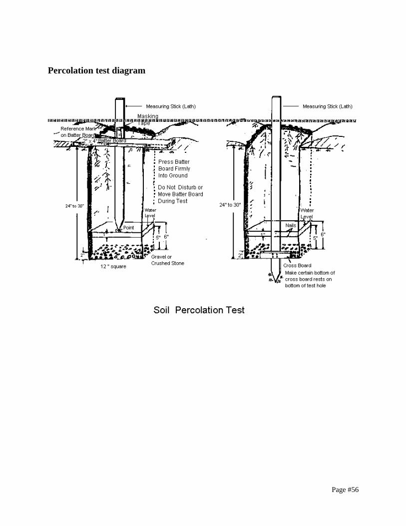
Page #56
Percolation test diagram

Page #57
POLICY STATEMENT ON SUBMISSION OF ELECTRONIC COPIES OF
PLANS
June 5, 2014 Re: Engineering Plan Submittal to the Dutchess County Dutchess County Department of Behavioral & Community Health Dear Sir or Madam: This letter is to inform you of a change in protocol for the submittal of engineering plans to the Dutchess County Department of Behavioral & Community Health. Historically this office has required three paper copies of plans and associated documents as part of each submittal. Due to a change in the manner this office will be storing our records all future submittals this office is asking for the following changes.
When submitting for engineering plan reviews please provide one paper copy and one electronic copy of your initial submittal. The documents need to be in a portable document format (pdf).
Once a project is ready for approval and signatures submittal of an electronic copy and three paper copies (of the plan and associated documents) are required.
As in the past one paper copy of the plan and associated documents will be returned to the preparer once they have been signed for approval.
We appreciate your cooperation with this change and it is our hope that it may save you some
operational costs associated with multiple plan set copies during initial and re-reviews.
Sincerely, Tanya Clark, P.E. Director Division of Environmental Health Services
cc: P. Marlow
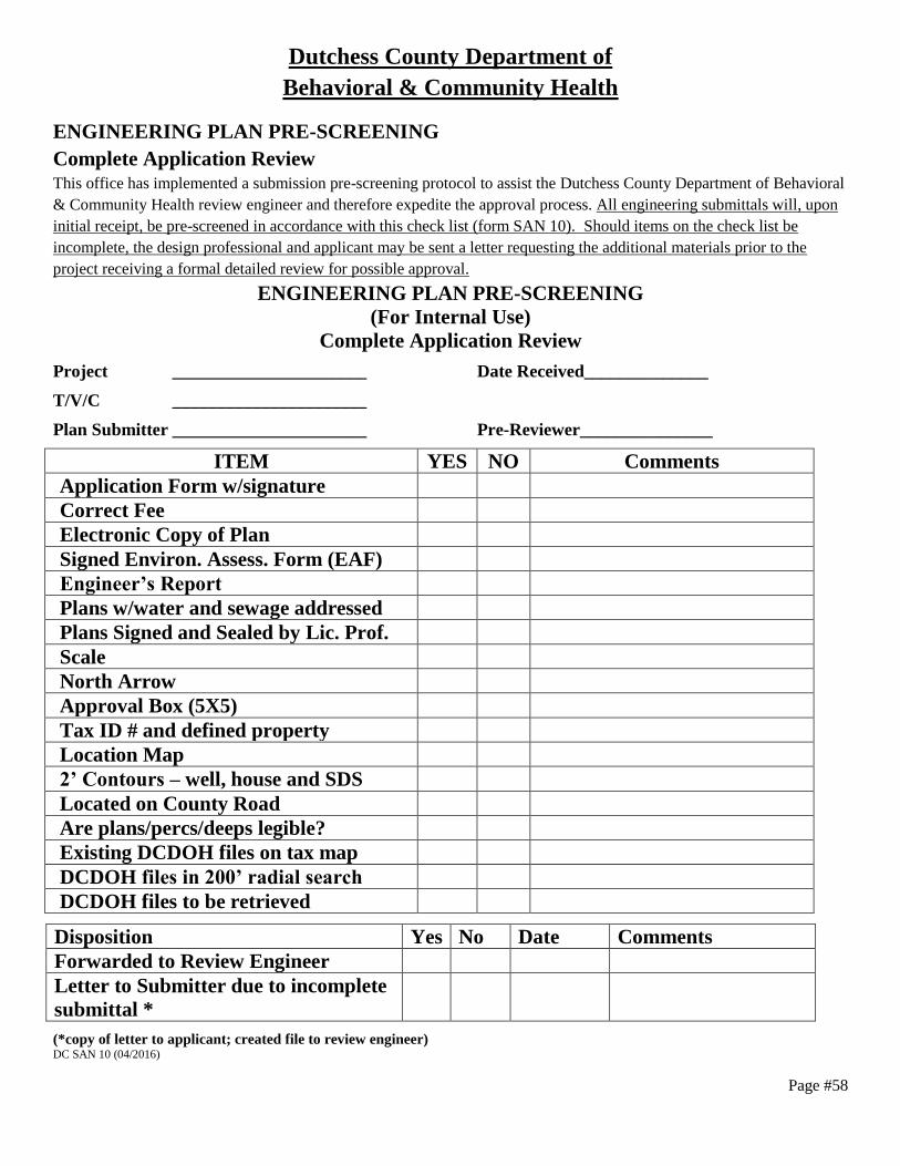
Page #58
Dutchess County Department of
Behavioral & Community Health
ENGINEERING PLAN PRE-SCREENING
Complete Application Review This office has implemented a submission pre-screening protocol to assist the Dutchess County Department of Behavioral
& Community Health review engineer and therefore expedite the approval process. All engineering submittals will, upon
initial receipt, be pre-screened in accordance with this check list (form SAN 10). Should items on the check list be
incomplete, the design professional and applicant may be sent a letter requesting the additional materials prior to the
project receiving a formal detailed review for possible approval.
ENGINEERING PLAN PRE-SCREENING
(For Internal Use)
Complete Application Review
Project ______________________ Date Received______________
T/V/C ______________________
Plan Submitter ______________________ Pre-Reviewer_______________
ITEM YES NO Comments
Application Form w/signature
Correct Fee
Electronic Copy of Plan
Signed Environ. Assess. Form (EAF)
Engineer’s Report
Plans w/water and sewage addressed
Plans Signed and Sealed by Lic. Prof.
Scale
North Arrow
Approval Box (5X5)
Tax ID # and defined property
Location Map
2’ Contours – well, house and SDS
Located on County Road
Are plans/percs/deeps legible?
Existing DCDOH files on tax map
DCDOH files in 200’ radial search
DCDOH files to be retrieved
Disposition Yes No Date Comments
Forwarded to Review Engineer
Letter to Submitter due to incomplete
submittal *
(*copy of letter to applicant; created file to review engineer) DC SAN 10 (04/2016)

Page #59
SUBMISSION STANDARDS GUIDE AND CHECKLIST
Item Description Completed
Application form is complete with owner’s signature (HD-1, DOH-348 – PWS)
Review fee as per attached fee schedule
Short Environmental Assessment Form with Parts I and II is completed or proof of SEQR
determination by the lead agency
Engineer’s Report with engineer’s seal and signature explaining at a minimum the project and
approval requested, any agreements for the project, and all supporting documentation such as
calculations and specifications, one copy for initial review
Complete set of plans provided, or indicate which pages of the drawing set are omitted
One set of plans shall be submitted for the initial review for approval. Two prints and a mylar
shall be submitted for final approval when the plan is to be filed with the County Clerk. Three
prints shall be submitted for final approval when the plans are not to be filed with the County
Clerk.
Electronic copy of the plan shall be submitted with the final approved plan set
The size of all plans shall be 36” x 48” or less
Name of applicant, which shall include but not be limited to a person, partnership, corporation
or other legal entity undertaking or participating in the establishment of the subdivision,
property, or lot(s) is included on plans
Owner familiarity note and signature is provided
Name, address, phone number, professional seal and signature of the design professional is
provided on Engineering Plans
Proof of preliminary planning board approval is provided, where applicable
Filed Map number is provided for previously approved realty subdivisions
Name of the subdivision, property, or lots under which the map shall be filed and/or approved;
including historical name
Approval Box (5” x 5”) or standard approval verbiage included on plan
Location map is provided with north arrow and nearest cross streets clearly labeled
Tax ID number(s) of property(ies) is(are) provided
Defined property on engineering plan with zoning and total acreage provided
Plans must show only lots for which approval is requested for sewage disposal and/or water
supply and their relationship to other property that is developed or might be developed and
such other information as may be needed to make a proper review.
North Arrow is provided on plans
Scale of drawings and legend provided on plans
Engineering plans showing arrangements for water supply and sewage disposal are provided
Two foot topographical contours surrounding the well, house, and SDS. Existing and proposed
topographical contours shall be shown
The number of bedrooms is indicated for each lot
Name of municipality of which the property resides in is provided on plans
Applicable DC EHSD Map Notes shall be included on the plan (see DC EHSD Map Notes)
All subdivisions (3 or more lots) test well policy applies for individual well subdivisions
All subdivision (2 or more lots) are surveyed and metes and bounds shown at design scale.
Lots are numbered or lettered for identification purposes.
On an individual lot or property, metes and bounds are shown and the origin of the survey shall
be referenced.
Deep and percolation test locations and results are provided on plans
Existing and/or proposed driveway and dwelling are provided on plans
Lots on County roads are indicated on plans
Stormwater and erosion control measures, existing or proposed, temporary or permanent, are
shown to determine separation adequacy to wells and OWTS components
Means of erosion control during construction, including details, are provided on plans
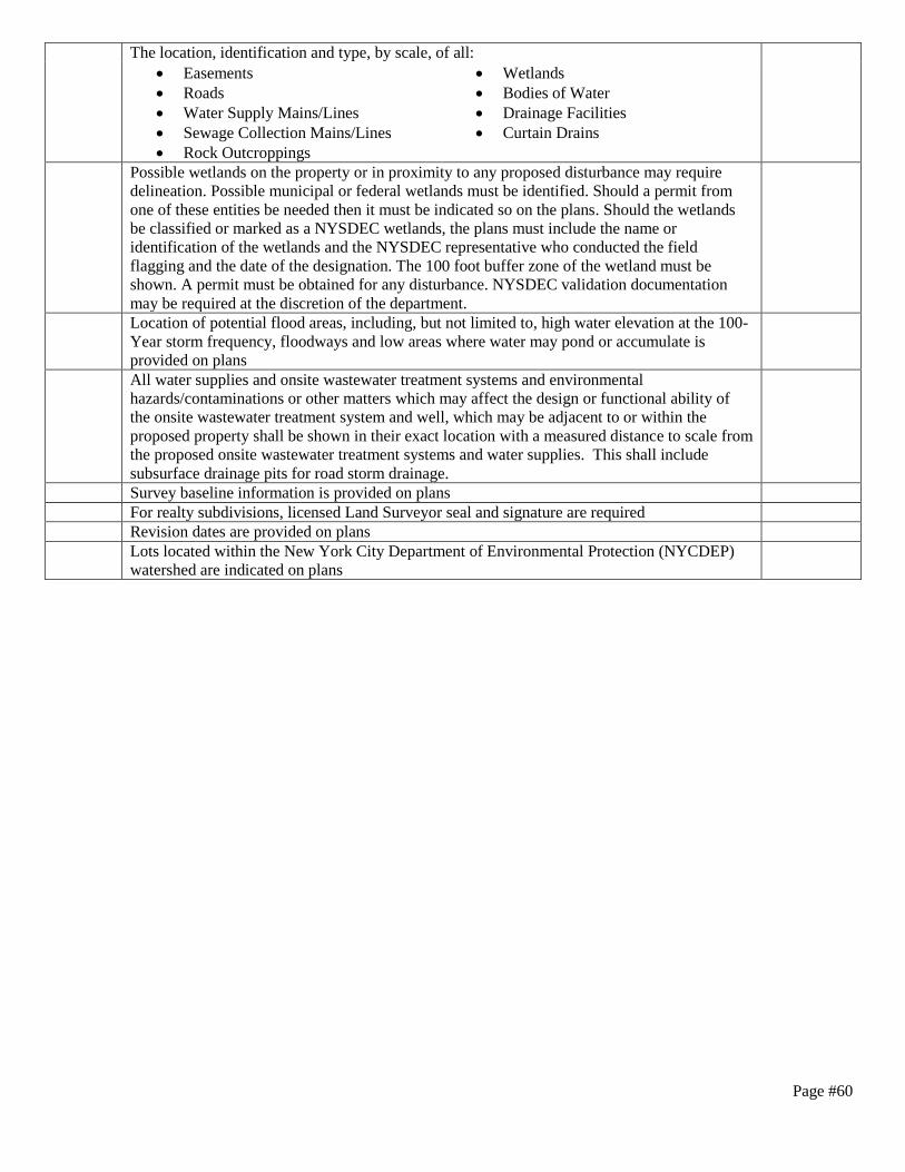
Page #60
The location, identification and type, by scale, of all:
Easements
Roads
Water Supply Mains/Lines
Sewage Collection Mains/Lines
Rock Outcroppings
Wetlands
Bodies of Water
Drainage Facilities
Curtain Drains
Possible wetlands on the property or in proximity to any proposed disturbance may require
delineation. Possible municipal or federal wetlands must be identified. Should a permit from
one of these entities be needed then it must be indicated so on the plans. Should the wetlands
be classified or marked as a NYSDEC wetlands, the plans must include the name or
identification of the wetlands and the NYSDEC representative who conducted the field
flagging and the date of the designation. The 100 foot buffer zone of the wetland must be
shown. A permit must be obtained for any disturbance. NYSDEC validation documentation
may be required at the discretion of the department.
Location of potential flood areas, including, but not limited to, high water elevation at the 100-
Year storm frequency, floodways and low areas where water may pond or accumulate is
provided on plans
All water supplies and onsite wastewater treatment systems and environmental
hazards/contaminations or other matters which may affect the design or functional ability of
the onsite wastewater treatment system and well, which may be adjacent to or within the
proposed property shall be shown in their exact location with a measured distance to scale from
the proposed onsite wastewater treatment systems and water supplies. This shall include
subsurface drainage pits for road storm drainage.
Survey baseline information is provided on plans
For realty subdivisions, licensed Land Surveyor seal and signature are required
Revision dates are provided on plans
Lots located within the New York City Department of Environmental Protection (NYCDEP)
watershed are indicated on plans

Page #61
SPECIFIC PROJECT BASED CHECKLIST – ONSITE WASTEWATER
TREATMENT SYSTEM (OWTS) Item Description Completed
RAW SEWER LINE AND EFFLUENT PIPING
Minimum of twenty-five (25) feet to stream, ten (10) feet to property line, fifty (50) feet to
well, ten (10) feet to culvert pipe, twenty-five (25) feet to open drainage, twenty-five (25) feet
to stormwater management practice, ten (10) feet to in-ground swimming pool, and twenty-five
(25) feet to top of embankment and/or retaining wall
Size and material of pipe is provided for raw sewer line
A minimum of ¼” per foot slope shall be provided from the building to the septic tank
No bends in the raw sewer line are proposed
The minimum raw sewer line invert elevation at the building line is provided on the plans
Size and material of pipe is provided for effluent line
A minimum of 1/8” per foot slope shall be provided from the septic tank and/or dosing
chamber to the OWTS area, for gravity systems
Cleanouts are provided at bends on effluent pipe if bends are necessary. Bends are a maximum
of forty-five (45) degrees
Cleanouts are proposed every seventy-five (75) feet on gravity lines (raw and effluent), where
applicable
Adequate earth coverage is provided over raw sewer line and effluent pipes
SEPTIC TANK
Minimum of ten (10) feet to dwelling, fifty (50) feet to stream and/or surface water, ten (10)
feet to property line, fifty (50) feet to well, one-hundred (100) feet to public water supply well,
twenty-five (25) feet to culvert pipe, twenty-five (25) feet to open drainage, fifty (50) feet to
stormwater management practice, twenty (20) feet to in-ground swimming pool, and twenty-
five (25) feet to top of embankment and/or retaining wall
One compartment if tank does not exceed 9’-11” and two compartments are provided for tanks
greater than ten (10) feet in length
A minimum two (2) inch elevation difference between influent and effluent pipe in septic tank
is provided
Septic tank capacity provided on plans/detail, and is sufficient for proposed bedroom/design
flow, tank labeled on plan view
Septic tank openings are water-tight and childproof
Septic tank requires interior and/or exterior coating, where applicable
Sanitary tees and baffles are provided and properly sized
Gas deflector and effluent filter are provided, where applicable
Minimum liquid surface area is provided and sufficient
Water-tight joints are provided at influent and effluent pipes
Septic tank dimensions are provided on plan, with a length to width ratio between 2:1 and 4:1
Concrete tank provides a minimum strength of 3,000 psi, and a minimum concrete wall
thickness of three (3) inches with reinforcement is provided
Depth of cover does not exceed loading rate of septic tank
Buoyancy for components when water table would impact structures
Residential septic tanks delivered in sections must be water-tight tested and certified by design
professional. Any commercial tanks must be tested and certified
Access to grade manhole is provided where earth coverage is greater than twelve (12) inches,
or a location stake is provided where earth coverage is less than twelve (12) inches
Septic tank is certified for H-20 loading, where applicable
Plan and section view of septic tank is provided
Typical septic tank detail is provided
Existing septic tanks to be abandoned are indicated with procedures on abandonment, where
applicable

Page #62
DISTRIBUTION BOX
Minimum of twenty (20) feet to dwelling, one-hundred (100) feet to stream, ten (10) feet to
property line, one-hundred (100) feet to well, thirty-five (35) feet to culvert pipe, fifty (50) feet
to open drainage, one-hundred (100) feet to stormwater management practice, thirty-five (35)
feet to in-ground swimming pool, and fifty (50) feet to top of embankment and/or retaining
wall
Plan and section view of distribution box is provided
Distribution box dimensions are provided on plans/detail
Outlets shown at a minimum nine (9) inches on center, or documentation that box is not too
small is provided
Two (2) inch elevation difference between inlet and outlet pipes is provided
A baffle is provided in distribution box
All outlets are set at same elevation
A minimum of twelve (12) inches of sand or pea gravel bedding is provided
A maximum of twelve (12) inches of earth coverage is provided
A minimum of two (2) feet of solid pipe is provided before lateral
Typical distribution box detail is provided
DROP BOX
Plan and section view of drop box are provided, where necessary
Drop box dimensions are provided on plans/detail
Box outlets shown 1¼” inches above lateral outlet(s)
Lateral outlets shown two (2) inches above floor
Minimum of two (2) feet of solid pipe is provided before lateral
A minimum of twelve (12) inches of sand or pea gravel bedding is provided
A maximum of twelve (12) inches of earth coverage provided
Drop boxes have locations stakes, provide baffles, speed levelers, laterals cut flush, with an
inlet invert at a minimum, one (1) inch above the outlet invert, where applicable (butterfly type
system for optimum use)
Distribution box is labeled in plan view
Velocity dissipation prior to distribution box is provided, where applicable
Typical drop box detail is provided
PUMP/DOSING CHAMBERS-INDIVIDUAL HOUSEHOLD SYSTEMS
Licensed professional engineer to certify pump/dosing chamber installation and testing
Licensed professional engineer to certify siphon chamber installation and testing
Pump calculations (TDH, velocity, pump curve, etc.…) are provided in Engineer’s Report
Plan and section view of pump/dosing chambers for each lot/bedroom are provided
Pumping noted for each lot, where applicable
Location of pump/dosing chamber shown for each lot
Buoyancy is taken into consideration for components when water table would impact
structures
Pump/dosing chamber is located after septic tank
A minimum of two (2) pumps are provided
Pumps made to alternate indicated on plans
Type of pump is specified
Make and manufacturer of pumps are provided on plans
Make and manufacturer of electrical controls are provided on plans, and installation in
conformance with National Electric Code, latest edition
Pipe, size, material, check valves, gate valves, lift chains, and weep holes are provided on
plans
A minimum of two (2) feet per second flow in force main is provided
Force main is designed for frost protection
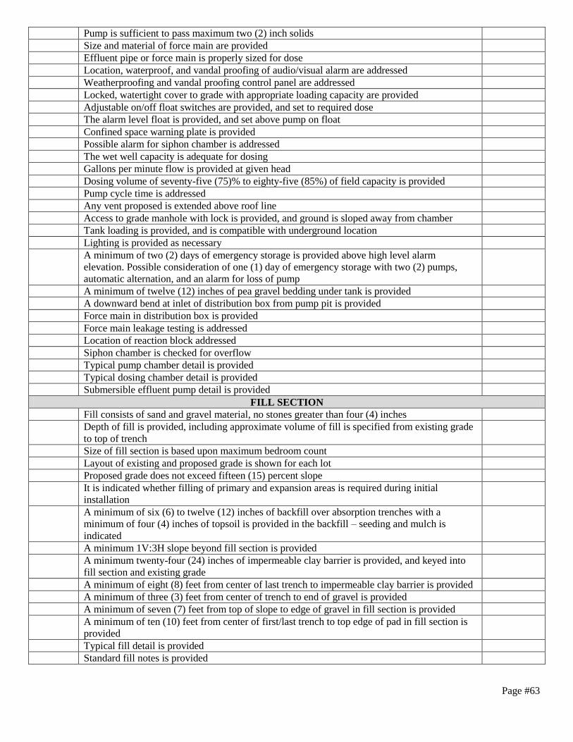
Page #63
Pump is sufficient to pass maximum two (2) inch solids
Size and material of force main are provided
Effluent pipe or force main is properly sized for dose
Location, waterproof, and vandal proofing of audio/visual alarm are addressed
Weatherproofing and vandal proofing control panel are addressed
Locked, watertight cover to grade with appropriate loading capacity are provided
Adjustable on/off float switches are provided, and set to required dose
The alarm level float is provided, and set above pump on float
Confined space warning plate is provided
Possible alarm for siphon chamber is addressed
The wet well capacity is adequate for dosing
Gallons per minute flow is provided at given head
Dosing volume of seventy-five (75)% to eighty-five (85%) of field capacity is provided
Pump cycle time is addressed
Any vent proposed is extended above roof line
Access to grade manhole with lock is provided, and ground is sloped away from chamber
Tank loading is provided, and is compatible with underground location
Lighting is provided as necessary
A minimum of two (2) days of emergency storage is provided above high level alarm
elevation. Possible consideration of one (1) day of emergency storage with two (2) pumps,
automatic alternation, and an alarm for loss of pump
A minimum of twelve (12) inches of pea gravel bedding under tank is provided
A downward bend at inlet of distribution box from pump pit is provided
Force main in distribution box is provided
Force main leakage testing is addressed
Location of reaction block addressed
Siphon chamber is checked for overflow
Typical pump chamber detail is provided
Typical dosing chamber detail is provided
Submersible effluent pump detail is provided
FILL SECTION
Fill consists of sand and gravel material, no stones greater than four (4) inches
Depth of fill is provided, including approximate volume of fill is specified from existing grade
to top of trench
Size of fill section is based upon maximum bedroom count
Layout of existing and proposed grade is shown for each lot
Proposed grade does not exceed fifteen (15) percent slope
It is indicated whether filling of primary and expansion areas is required during initial
installation
A minimum of six (6) to twelve (12) inches of backfill over absorption trenches with a
minimum of four (4) inches of topsoil is provided in the backfill – seeding and mulch is
indicated
A minimum 1V:3H slope beyond fill section is provided
A minimum twenty-four (24) inches of impermeable clay barrier is provided, and keyed into
fill section and existing grade
A minimum of eight (8) feet from center of last trench to impermeable clay barrier is provided
A minimum of three (3) feet from center of trench to end of gravel is provided
A minimum of seven (7) feet from top of slope to edge of gravel in fill section is provided
A minimum of ten (10) feet from center of first/last trench to top edge of pad in fill section is
provided
Typical fill detail is provided
Standard fill notes is provided

Page #64
ONSITE WASTEWATER TREATMENT SYSTEM
Minimum of twenty (20) feet to dwelling, one-hundred (100) feet to stream and/or surface
water, fifty (50) feet to recharge system, ten (10) feet to property line, one-hundred (100) feet
to wells uphill, two-hundred (200) feet to wells downhill, thirty-five (35) feet to in-ground
swimming pool
A minimum of four (4) feet separation distance between groundwater and trench bottom is
provided
A minimum of five (5) feet separation distance between rock or impermeable layer, and trench
bottom is provided
Results of percolation (stabilized rate and depth) testing are provided, and presoaking of
percolation holes has been addressed
Percolation Tests were conducted at a depth 24” to 30”
Percolation test form was signed by New York State professional engineer
Results of deep (soil strata, depth, rock and water depth) testing are provided
A minimum of one (1) deep test in the primary and one (1) deep test in the expansion areas are
provided
Deep tests were witnessed by Department of Behavioral & Community Health
The primary and replacement OWTS is shown in the exact location(s) to be constructed, by
scale to the property lines. With an individual lot greater than five (5) acres, the exact location
of the OWTS is shown by a minimum of two permanent reference points
Absorption trenches are two (2) foot in width
Absorption trenches are six (6) feet on center
Maximum length of lateral do not exceed sixty (60) feet for gravity, and one-hundred (100)
feet for dosed systems
The number of rows and length of each trench clearly labeled on plan
Trench depth is between eighteen (18) and thirty (30) inches
A minimum of two (2) feet of solid pipe is provided at the beginning of each absorption trench
provided
Capped ends of each absorption trench are provided
Layer of untreated building paper is addressed
A minimum of six (6) to twelve (12) inches of backfill, including four (4) inches of topsoil, is
provided over absorption trenches
Impermeable clay barrier is provided, where applicable in fill pads
The raw invert elevation is provided for each lot
A layout is provided for the maximum bedroom proposed
The size of field is compatible with soil information observed in deep tests and percolation
tests
An area for 100% replacement is provided
Absorption fields are shown parallel to existing or proposed contours
Drop boxes are provided for slopes greater than ten (10) percent, where applicable
Maximum slope within OWTS area is fifteen (15) percent
An absorption field schedule is provided, including minimum depth
The total number of trench length is provided with the number of rows and lengths of each
trench provided
Absorption fields to be installed with ¾” to 1½” clean crushed stone or washed gravel
Trench bottom shall be graded level
Maximum trench depth is provided
Longitudinal and cross section of trench are provided
Size, type and slope of perforated pipe are provided
Curtain drain is provided with rip rap, day lighted, and screened for rodents, and certification
requirement, where applicable
Curtain drain is a minimum ten feet from laterals if solid pipe, twenty feet from laterals if
perforated pipe. Also see figure 19A of NYSDOH Design Handbook – 2012.

Page #65
A swale is provided to divert direct flow away from the OWTS area, where applicable
Distribution box is provided at a minimum for all pump pits/dosing chambers proposed
A design schedule for primary and replacement OWTS for each lot for 3 and 4 bedroom
homes or facility includes at a minimum the required number, length and width of absorption
trenches, required absorptive area, fill depth requirement, type of distribution device regardless
of dosed, gravity or pressure
If the design criterion includes provisions for four (4) or more bedrooms, the area for
infiltration, including the replacement area, is shown for the maximum number of bedrooms or
the plan may specifically designate that the design shall only accommodate a maximum of the
number designed for
All grading and installation of curtain drains and drainage systems affecting more than one
contiguous lot must be completed and certified in writing by the design professional that it has
been completed prior to final approval
Existing and proposed field contours are shown, using a two foot maximum interval in the
location of the house or facility, onsite wastewater treatment system, and well. Contours
elsewhere are shown at a maximum of five feet. The origin of the topographic survey is
referenced
Grading provides for adequate collection and drainage of surface and groundwater that may
impact design and functional ability of the sewage disposal system and well. OWTS profiles
are included
Typical absorption field detail is provided
Sewage disposal details (e.g. absorption trench, fill section, curtain drain) are provided on plan
Protection of OWTS area from animal and vehicular traffic, where necessary. Flagging of
OWTS area for protection prior to any site regrading or construction is addressed
OWTS area is increased by five (5) percent if water treatment discharge connection is
expected
Notes are provided for lots with existing wells and/or onsite wastewater treatment systems
Standard Dutchess County Department of Behavioral & Community Health notes are provided
SEEPAGE PITS
Plan and sectional are provided
A minimum of four (4) feet separation distance between groundwater and trench bottom is
provided
A minimum of five (5) feet separation distance between rock and trench bottom is provided
The raw invert elevation is provided
A layout is provided for the maximum bedroom proposed
The size of field is compatible with soil information observed in deep tests
An area for 100% expansion is provided
A minimum separation of three (3) times of the effective diameter is provided
A seepage pit field schedule is provided
The number of seepage pits are specified
Pit diameter and effective depths are indicated
Watertight joints above inlet are provided
Untreated building paper/filter and backfill is specified
Precast concrete or cement block pit is specified on plans
An access cover is provided at a minimum twenty (20) inches
Twelve (12) inches of earth coverage is provided above pit
A minimum 6” to 12” annular ring of 2½” to 4” stone (commercial) or ¾” to 2½” (residential)
is provided
Footing and coarse gravel are provided at bottom
Typical seepage pit detail is provided
No wells are within one-hundred and fifty (150) feet downhill and two-hundred (200) feet
uphill of a well.

Page #66
SPECIFIC PROJECT BASED CHECKLIST – CENTRAL WATER
Item Description Completed
Design meets the Ten States Standards
Design of source, treatment plant, and distribution system are provided, where applicable
The central water main is shown in the exact location to be installed, by scale to the property
lines.
Water service lines from the well or water main to the building are shown on the plans.
Water main location, material, size, and cover are provided
A water main profile is provided with all crossings, services and appurtenances shown
The name of public water supply, municipal water system, or water district is provided
Indication whether the public water supply is an expansion of existing, or a proposed system is
provided
Hydraulic analysis which demonstrates that the minimum required distribution system
pressures are available during all conditions of flow is provided
A demonstration that sufficient source, treatment and storage capacities are available within the
water system to support the existing and proposed infrastructure is provided
Test well locations and quality testing protocol were approved by DC EHSD prior to
construction and testing
The required fire flow capacity is provided
Water meters and backflow prevention are provided on plans, where applicable
Water meters are provided for commercial projects
Valve spacing every five-hundred (500) feet (commercial) or eight-hundred (800) feet (other),
and hydrant and air relief spacing every three-hundred and fifty (350) feet to six-hundred (600)
feet, where applicable
A minimum of ten (10) feet horizontal separation distance from sewer and drainage
components (e.g. manholes, catch basins, pipes), and eighteen (18) inches vertical separation
distance from sewer and drainage collection systems is provided
A minimum of five (5) feet of earth coverage is provided over pipe
A water works corporation is provided, where applicable
A transportation corporation is provided, where applicable
Thrust restraints and mechanical joints are provided
Specifications are provided
Pressure testing procedures are provided on plan
Leakage testing procedures are provided on plan
Disinfection procedures are provided on plan
NYSDEC Water supply permit and application are provided, where applicable
Agreements or contracts required for proposed project are provided
Letter of approval from water company is provided, where applicable
Water supply details (e.g. trench, hydrant, service line, thrust block/restrained joint,
stream/wetland crossing, pipe crossing, water service line) are provided
Standard Health Department notes are provided
Additional notes are provided for projects with central utilities

Page #67
SPECIFIC PROJECT BASED CHECKLIST – CENTRAL SEWER
Item Description Completed
Design meets the Ten States Standards
The central sewer main is shown in the exact location to be installed, by scale to the property
lines.
Plant design is included with central sewer, where applicable
Private or municipal sewer district distinction is provided
All lots have been designed to be served for sewer
It is indicated whether central sewer is expansion of existing system, or proposed new
construction
A demonstration that sufficient source, treatment and storage capacities are available within the
sewer system to support the existing and proposed infrastructure is provided
A sewer main profile is provided with all crossings, services and appurtenances shown
A sewage collection system provides for one-hundred (100) percent gravity flow
Location, size and slope of sewer mains and laterals are provided
It is indicated whether pump station is required, and provide design of pump station
A minimum of ten (10) feet horizontal separation distance from water components (e.g. mains,
service lines, hydrants), and eighteen (18) inches vertical separation distance from water
systems is provided
A maximum of four-hundred (400) feet of spacing between sewer manholes not exceeded for
pipes with a diameter of fifteen (15) inches or less is provided
A minimum of two (2) feet of earth coverage for mains and laterals located under pavement, or
one (1) feet of earth coverage for mains and laterals located under lawn are provided
Transportation corporation are provided, where applicable
Pressure testing procedures are provided on plan
Leakage testing procedures are provided on plan
Deflection (light or mandrel) are procedures provided on plan
NYSDEC SPDES permit is provided, where applicable
Typical central sewer details (e.g. trench, manhole, lateral, pipe crossing, stream/wetland
crossing, pump station, force main, etc…) are provided
Standard Health Department notes are provided
Additional notes are provided for projects with central utilities

Page #68
SPECIFIC PROJECT BASED CHECKLIST – INDIVIDUAL WATER SUPPLY
Item Description Completed
The individual water supply is shown in the exact location to be installed, by scale to the
property lines. With an individual lot greater than five (5) acres, the location of the well is
shown by a minimum of two permanent reference points
Well location is accessible for well rig for drilling, and is accessible after lot development
Water service lines from the well or water main to the building are shown on the plans.
Well separation is provided on existing and proposed wells, two-hundred (200) feet separation
distance from uphill OWTS, one-hundred (100) feet separation distance from downhill OWTS,
and one-hundred (100) feet from stormwater ponds used for road drainage. Well location
relative to flood zones and possible sources of contamination are addressed
A minimum distance of fifteen (15) feet of separation from property lines, fifty (50) feet of
separation from septic tanks, one-hundred and fifty (150) feet of separation from seepage pit
and twenty-five (25) feet of separation from stream, lake and/or wetland course
An individual well for each lot is provided
A pitless adaptor is provided below frost line (four (4) feet and six (6) inches minimum earth
cover)
A minimum of fifty (50) feet of casing, ten (10) feet minimum into rock, with twelve (12)
inches minimum casing extended above ground is provided
Additional separation distances for casing depth less than fifty (50) feet, or installation into
gravel is provided
Mounded earth coverage around well for additional protection is provided, where applicable
A sanitary seal cap is provided
Test well locations and quality testing protocol were approved by DC EHSD prior to
construction and testing. Three or more lots require a test well. Test well notes provided on
plans, where applicable
Water meters are provided for commercial projects
Typical water supply details (e.g. well or water service) are provided on plans
Well to be installed per the requirements of 5-B 10NYCRR
Standard Health Department notes are provided

Page #69
SPECIFIC PROJECT BASED CHECKLIST –
EXISTING WELLS FOR FUTURE USE APPROVAL
Item Description Completed
The individual water supply is shown in the exact location, by scale to the property lines.
Water service lines from the existing well to the building are shown on the plans.
The existing well is accessible for maintenance
Well separation is provided on existing wells; two-hundred (200) feet separation distance from
uphill OWTS, one-hundred (100) feet separation distance from downhill OWTS, and one-
hundred (100) feet from stormwater ponds used for road drainage. Well location relative to
flood zones and possible sources of contamination are addressed
A minimum distance of fifty (50) feet of separation from septic tanks, one-hundred and fifty
(150) feet of separation from seepage pit and twenty-five (25) feet of separation from stream,
lake and/or wetland course
Consideration is taken for possible water quality testing
For residential purposes, the well is capable of a minimum five (5) gallons per minute
A Well Completion Report is provided
The existing well is considered viable for use (meets contemporary construction standards)
Is there a minimum six (6) inch casing above grade (wells in pits are not allowed)
A sanitary seal cap is provided
Existing water well separation distances from contaminant sources shall be increased by 50%
whenever the aquifer enters the well at less than 50-feet below grade (casing less than 50 feet
in length)
Mounded earth coverage around existing well for additional protection is provided, where
possible
Is there a working submersible pump available within the existing well (point wells, cisterns,
springs are not allowed)
If the well subject to flooding, mitigation is properly addressed
Water meters are provided for commercial projects
Typical water supply details (e.g. proposed water service line) are provided on plans
Existing well is in conformance with Appendix 5-B
Consider a location reserved for a future replacement well
Existing well is approvable subject to a designed pump test for quantity.
Standard Dutchess County Department of Behavioral & Community Health notes are provided
for existing wells

Page #70
Policy & Procedure
INDIVIDUAL WELL APPROVAL & DETERMINING ADEQUACY OF
WATER SUPPLY
Wells shall be developed and maintained in accordance with the New York State Department of
Health, Appendix 5-B of the New York State Sanitary Code and the Dutchess County Department of
Behavioral & Community Health and New York State Department of Health rules, regulations, policies
and procedures.
The design engineer shall demonstrate the adequacy of the water supply in accordance with the
following:
a) DC EHSD Plan Submission Guide for Subdivisions and Individual Lots.
b) A minimum of one test well representatively spaced for each five (5) lots or fraction
thereof.
c) Sustained well yield by use of an acceptable test as determined by the design engineer.
d) DC EHSD policy and standards also apply to existing wells for future use approval.
Note: The well driller's air test will not be acceptable for well yields of less than five (5) gallons
per minute. This includes lots which have not had the benefit of a test well. When used, the air
test shall be of a duration sufficient to accurately determine the true well yield.
Note: By prior approval of the DC EHSD review engineer, water quality tests may not be
required for every test well.
Note: All test wells shall be protected from vandalism and contamination.
A well with less than five (5) gallons per minute, but not less than two (2) gallons per minute,
may be accepted based upon an acceptable report prepared by a professional engineer or other person
acceptable to the Department which shall include, but not be limited to, the following:
1) Submission of a "Well Completion Report".
2) The well shall be pump tested for yield and drawdown. The test pump shall have a
capacity at least equal to the pumping rate at which it is expected the well will be pumped
down. The test pump shall be installed to operate continuously until the water level and
yield have stabilized. The stabilized water level and yield shall be maintained for a
minimum of four hours’ duration. Upon termination of pumping, well recovery shall be
observed until the original static water level is reached. Pump test data, including
complete water level observations and well pumping rate, shall be provided with the
engineering report.
3) A pump curve for the installed or recommended well pump shall be submitted.

Page #71
4) All wells shall produce a minimum sustained yield of two (2) gallon per minute. With
wells that yield two to three gallons per minute, the well pump shall require a low water
or low pressure cutoff.
5) All systems shall provide 400 gallons of storage at peak demand, either by means of an
external storage tank or useable well storage measured from the static water level to a
point 4 feet above the pump intake.
If external well storage is proposed, a sketch of the system and equipment specifications
shall be submitted for approval.
For systems providing in-well storage, the pump capacity shall be five (5) gallons per
minute at the lowest pumping level and a minimum of 30 PSIG in the house system.
6) A hydropneumatic tank providing a minimum drawdown of at least 20 gallons at the
regular system pressure range (30-50 PSIG) shall be provided.
7) Prior to final approval, the Department shall require in writing from either the engineer,
developer or property owner that construction and installation was completed in
accordance with any approvals and this guideline.
Note: Subdivisions with fifty (50) lots or more shall require a waiver from central water. This
includes contiguous or adjacent parcels which may be developed separately. Consideration will
be given to a waiver only after the submission of an engineering report with adequate information
to justify such waiver.
Note: This standard and guideline should not be interpreted to mean that wells with yields of less
than five (5) gallons will be accepted for new projects or in lieu of central water.

Page #72
ADDENDUM TO STANDARDS & GUIDELINES FOR INDIVIDUAL
WELL APPROVAL
The individual water supply shall be shown in the exact location to be installed, by scale
to the property lines. With an individual lot greater than five (5) acres, the location of the
well may be shown by a minimum of two permanent reference points. The location of
the well shall be certified as being accessible for the installation and installation of the
service line to the dwelling. If installation of the service line is through rock which must
be removed, it shall be shown or noted.
The DC EHSD, prior to approval of a plan, reserves the right to require test wells and
supporting information to determine if the proposed individual water supply will be
adequate in quantity and quality and potable and unobjectionable in physical and
chemical quality and not be or become so polluted or subject to such pollution as to
constitute a menace or potential menace to the public health or the health of persons
using or who may use the water thereby supplied and not have an adverse effect on
surrounding development.
No subdivision of three (3) or more lots or one parcel of an unapproved realty
subdivision (1115 PHL) shall be approved until the plans demonstrate the availability of
a water supply of dependable quality and quantity by test well(s).
For subdivisions of less than three (3) lots, one individual residential lot and design flows
less than 1000 gallons per day, the availability of water supply of dependable quality and
quantity may be demonstrated by test well(s) or, in lieu of test wells, a report by the
design engineer that can demonstrate the adequacy of the existing or proposed water
supply.
ADEQUATE QUALITY - New York State Part 5 drinking water maximum
contaminant levels.
If the maximum contaminant levels are or may be exceeded, the DC EHSD may
require treatment, central water or an advisory note to be placed on the approved
plan for the benefit of the purchaser or user.
ADEQUATE QUANTITY - The water supply shall yield a minimum of five (5)
gallons per minute for residential lots. If the yield is less than five (5) gallons per
minute, then the DC EHSD standard and guideline, "Individual Well Approval
and Determining Adequacy of Water Supply", shall apply. Approvals for non-
residential parcels may require a minimum yield of greater than five (5) gallons
per minute.
Prior to plan approval, all test wells shall require a permit to construct, well completion
report and quality/quantity test results to be made part of the submission for approval.
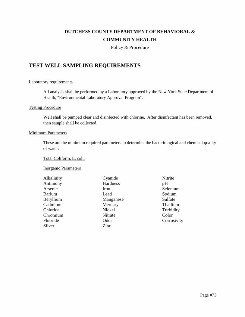
Page #73
DUTCHESS COUNTY DEPARTMENT OF BEHAVIORAL &
COMMUNITY HEALTH
Policy & Procedure
TEST WELL SAMPLING REQUIREMENTS
Laboratory requirements
All analysis shall be performed by a Laboratory approved by the New York State Department of
Health, "Environmental Laboratory Approval Program".
Testing Procedure
Well shall be pumped clear and disinfected with chlorine. After disinfectant has been removed,
then sample shall be collected.
Minimum Parameters
These are the minimum required parameters to determine the bacteriological and chemical quality
of water:
Total Coliform, E. coli.
Inorganic Parameters
Alkalinity
Antimony
Arsenic
Barium
Beryllium
Cadmium
Chloride
Chromium
Fluoride
Silver
Cyanide
Hardness
Iron
Lead
Manganese
Mercury
Nickel
Nitrate
Odor
Zinc
Nitrite
pH
Selenium
Sodium
Sulfate
Thallium
Turbidity
Color
Corrosivity

Page #74
Principal Organic Chemicals
benzene cis-1,3-dichloropropene
bromobenzene trans-1,3-dichloropropene
bromochloromethane ethylbenzene
bromomethane hexachlorobutadiene
n-butylbenzene isopropylbenzene
sec-butylbenzene p-isopropyltoluene
tert-butylbenzene methylene chloride
carbon tetrachloride n-propylbenzene
chlorobenzene styrene
chloroethane 1,1,1,2-tetrachloroethane
chloromethane 1,1,2,2-tetrachloroethane
2-chlorotoluene tetrachloroethene
4-chlorotoluene toluene
dibromomethane 1,2,3-trichlorobenzene
1,2-dichlorobenzene 1,2,4-trichlorobenzene
1,3-dichlorobenzene 1,1,1-trichloroethane
1,4-dichlorobenzene 1,1,2-trichloroethane
dichlorodifluoromethane trichloroethene
1,1-dichloroethane trichlorofluoromethane
1,2-dichloroethane 1,2,3-trichloropropane
1,1-dichloroethene 1,2,4-trimethylbenzene
cis-1,2-dichloroethene 1,3,5-trimethylbenzene
trans-1,2-dichloroethene m-xylene
1,2-dichloropropane o-xylene
1,3-dichloropropane p-xylene
2,2-dichloropropane Vinyl chloride
1,1-dichloropropene MTBE
EPA method 502.2 or EPA method 524.2 with a detection limit of 0.5 µg/l or less.
Other Parameters
There may be additional chemical, microbiological, bacteriological and physical
parameters which may be required by the review engineer to assess the quality of water because
of suspected or known environmental hazards and site specific concerns, waste disposal sites,
orchards, agricultural land uses, oil and chemical spills.
NOTE: Prior to conducting tests to determine the physical, bacteriological and chemical quality
of the water, the design person should contact and consult with the DC EHSD review engineer to
establish criteria for the number of test wells, test wells to be sampled, and other parameters
which will require analysis.

Page #75
Reference & Standards:
Part 5, New York State Sanitary Code;
New York State Department of Health, New York State Department of Environmental
Conservation, Dutchess County Department of Behavioral & Community Health policies,
procedures, guidelines and technical standards.

Page #76
ENGINEERING REVIEW FEE SCHEDULE Engineering Review Fee Schedule
Type of Submission - Rates Effective January 1, 2014
Plan Approval Extension $200 + $125 ea. add'l lot
Individual Lot / Subdivision Lot $595
Individual well/individual SDS
$595/lot
Individual well or individual SDS $265/lot
Central water & central sewage $235/lot
Commercial SDS
< 1000 GPD $595
> 1000 GPD $595 + $65 per ea. 1000 gallons over 1000
PWS New Plant and Distribution System
Community, up to 10,000 gallons $1325
Community, over 10,000 gallons $1855
Non-community $695
Treatment system modification $330
Distribution system $330
STP - New Plant and Collection System
Up to 10,000 gallons $1060
Over 10,000 gallons $1590
Collection and/or pumping system $330
Swimming Pool
New $725
Modification of treatment $330
Individual Well Permits $45
Permission to File Map $65

Page #77
FORMS TABLE Please check our website, http://www.dutchessny.gov/, for copies of these and other forms
NAME OF FORM PAGES FORM No.
Applications
Application for Approval of Plans for a Wastewater Disposal System 2 HD-1
Application for Approval of Plans and Specifications for the
Construction of, or alterations to an artificial swimming Pool and
appurtenances.
2 Gen-134
Engineering Report for Swimming Pool Plans 4 DOH-1309
Application for Approval of Backflow Prevention Devices 1 DOH-347
Application for Approval of a Residential Sewage Disposal System 1 SAN 34
Application for Approval of Plans for Public Water Supply Improvement 1 DOH-348
Application for Access to Records 2 HD-FOIL1
Application for Extension of Approval 1 HD-164
Application for Approval of < 5 GPM Well 2 WW-2
Application to Construct or Abandon a Water Well 2 DC SAN 35
Sewer/Water Adequacy for New/Revised Use HD-ENH300
Wastewater Disposal System Registration & Notice of Intent 2 SAN 36
Short Environmental Assessment Form 3 NYSDEC
Website
Waiver Request Form 2 HD-160
Certifications
Fill Section Certification 2 HD-5
Certification of Construction Compliance 2 HD-159
Engineer’s Certification of Public Water Improvement Project Completion DOH-5025
Testing
Percolation Test Data 1 HD-184
Deep Test Results 1 HD-185
Other
Fee Schedule 1 N/A

Page #78
DUTCHESS COUNTY DEPARTMENT OF
BEHAVIORAL & COMMUNITY HEALTH
MAP NOTES
Standard Notes for Projects w/Central Water & Sewer
The design, construction and installation shall be in accordance with this plan and generally accepted
standards in effect at the time of construction which include:
“New York State Design Standards for Intermediate Sized Wastewater Treatment Systems”, NYSDEC
“Recommended Standards for Sewage Treatment Works, (Ten States).”
“Recommended Standards for Water Works, (Ten States).”
“New York State Department of Health and Dutchess County Environmental Health Services Division
policies, procedures and standards.”
“Dutchess County and New York State Sanitary Codes.”
“Dutchess County Environmental Health Services Division Certificate of Approval letter.”
This plan is approved as meeting the appropriate and applied technical standards, guidelines, policies and
procedures for arrangement of sewage disposal and water supply facilities.
Upon completion of the facilities, the finished works shall be inspected, tested, and certified complete to
the DC EHSD by the New York State licensed Professional Engineer supervising construction. No part of
the facilities shall be placed into service until accepted by the DC EHSD.
Approval of any plan(s) or amendment thereto shall be valid for a period of five (5) years from the date of
approval. Following the expiration of said approval, the plan(s) shall be re-submitted to the
Commissioner of Health for consideration for re-approval. Re-submission or revised submission of plans
and/or associated documents shall be subject to compliance with the technical standards, guidelines,
policies and procedures in effect at the time of the re-submission.
No cellar, footing, floor, garage, cooler or roof drains shall be discharged into the sewage collection
system.
All buildings shall be constructed at an elevation high enough to ensure gravity flow to the sewage
collection system.
All required Erosion & Sediment Control and Stormwater Pollution Prevention Water Quality & Quantity
Control structures, permanent and temporary, are shown on the plans.
The DC EHSD shall be notified sixty days prior to any change in use; use changes may require re-
approval by the DC EHSD.

Page #79
No buildings are to be occupied and the new water system shall not be placed into service, until a
“Completed Works Approval” is issued under section 5-1.22(d) of Part 5 of the New York State Sanitary
Code (10NYCRR5).
No buildings are to be occupied and the new wastewater collection system shall not be placed into service
until, a “Certificate of Construction Compliance” is issued under section 19.7 of Article 19 of the
Dutchess County Sanitary Code.
All service lines are the responsibility of the owner up to the property line. The water and sewer
companies shall be responsible for all valves and pipes which are not on the owner’s property.
The undersigned owners of the property hereon state that they are familiar with this map, its contents and
its legends and hereby consent to all said terms and conditions as stated hereon.

Page #80
Standard Notes for Central Sewer Projects (No Water)
The design, construction and installation shall be in accordance with this plan and generally accepted
standards in effect at the time of construction which include:
“New York State Design Standards for Intermediate Sized Wastewater Treatment Systems”, NYSDEC
“Recommended Standards for Sewage Treatment Works, (Ten States).”
“New York State Department of Health and Dutchess County Environmental Health Services Division
policies, procedures and standards.”
“Dutchess County and New York State Sanitary Codes.”
“Dutchess County Environmental Health Services Division Certificate of Approval letter.”
This plan is approved as meeting the appropriate and applied technical standards, guidelines, policies and
procedures for arrangement of sewage disposal.
Upon completion of the facilities, the finished works shall be inspected, tested, and certified complete to
the DC EHSD by the New York State registered design professional supervising construction. No part of
the facilities shall be placed into service until accepted by the DC EHSD.
Approval of any plan(s) or amendment thereto shall be valid for a period of 5 years from the date of
approval. Following the expiration of said approval, the plan(s) shall be re-submitted to the
Commissioner of Health for consideration for re-approval. Re-submission or revised submission of plans
and/or associated documents shall be subject to compliance with the technical standards, guidelines,
policies and procedures in effect at the time of the re-submission.
The DC EHSD shall be notified sixty days prior to any change in use; use changes may require re-
approval by the DC EHSD.
All required Erosion & Sediment Control and Stormwater Pollution Prevention Water Quality & Quantity
Control structures, permanent and temporary, are shown on the plans.
No buildings are to be occupied and the new wastewater collection system shall not be placed into service
until, a “Certificate of Construction Compliance” is issued under section 19.7 of Article 19 of the
Dutchess County Sanitary Code.
No cellar, footing, floor, garage, cooler or roof drains shall be discharged into the sewage collection
system.
All buildings shall be constructed at an elevation high enough to ensure gravity flow to the sewage
collection system.
All service lines are the responsibility of the owner up to the property line. The sewer company shall be
responsible for all valves and pipes which are not on the owner’s property.
The undersigned owners of the property hereon state that they are familiar with this map, its contents and
its legends and hereby consent to all said terms and conditions as stated hereon.
Page #81
Standard Notes for Commercial Projects (Onsite Water Source and Sewage
Disposal) – W/No PWS
The design, construction and installation shall be in accordance with this plan and generally accepted
standards in effect at the time of construction which include:
“New York State Design Standards for Intermediate Sized Wastewater Treatment Systems”, NYSDEC
“Appendix 75-A, Waste Treatment - Individual Household Systems, New York State Sanitary Code.”
“Recommended Standards for Sewage Treatment Works, (Ten States).”
“New York State Department of Health and Dutchess County Environmental Health Services Division
policies, procedures and standards.”
“Dutchess County and New York State Sanitary Codes.”
“Dutchess County Environmental Health Services Division Certificate of Approval letter.”
This plan is approved as meeting the appropriate and applied technical standards, guidelines, policies and
procedures for arrangement of sewage disposal and treatment and water supply facilities.
Upon completion of the facilities, the finished works shall be inspected, tested, and certified complete to
the DC EHSD by the New York State registered design professional supervising construction. No part of
the facilities shall be placed into service until accepted by the DC EHSD.
Approval of any plan(s) or amendment thereto shall be valid for a period of 5 years from the date of
approval. Following the expiration of said approval, the plan(s) shall be re-submitted to the
Commissioner of Health for consideration for re-approval. Re-submission or revised submission of plans
and/or associated documents shall be subject to compliance with the technical standards, guidelines,
policies and procedures in effect at the time of the re-submission.
All wells and onsite wastewater treatment system existing or approved within 300 feet of the proposed
wells and onsite wastewater treatment system are shown on this plan along with any other environmental
hazards in the area that may affect the design and functional ability of the onsite wastewater treatment
system and well.
It shall be demonstrated by the contractor to the DC EHSD field inspector and/or design professional that
the tank is sealed, watertight and acceptable for use. This shall require, at a minimum, the filling of the
tank with water to observe if it is in fact sealed, watertight and acceptable for use. The tank must also
meet any local testing requirements, including possible electrical and safety standards.
All proposed wells and service lines on this plan are accessible for installation and placement.
No cellar, footing, floor, garage, cooler or roof drains shall be discharged into the onsite wastewater
treatment system or within 50 feet of any well.
All buildings shall be constructed at an elevation high enough to ensure gravity flow to the onsite
wastewater treatment system.
Page #82
There shall be no vehicular traffic over the onsite wastewater treatment system. Prior to construction, the
area of the system shall be staked out and fenced off.
Onsite wastewater treatment systems shall not be installed in wet or frozen soil.
The DC EHSD shall be notified prior to the backfilling of any completed onsite wastewater treatment
system so that a final inspection may be performed.
The DC EHSD shall be notified sixty days prior to any change in use; use changes may require re-
approval by the DC EHSD.
All required Erosion & Sediment Control and Stormwater Pollution Prevention Water Quality & Quantity
Control structures, permanent and temporary, are shown on the plans.
The undersigned owners of the property hereon state that they are familiar with this map, its contents and
its legends and hereby consent to all said terms and conditions as stated hereon.

Page #83
Standard Notes for Commercial Projects (Onsite Water Source & Sewage
Disposal) – W/PWS
The design, construction and installation shall be in accordance with this plan and generally accepted
standards in effect at the time of construction which include:
“New York State Design Standards for Intermediate Sized Wastewater Treatment Systems”, NYSDEC
“Appendix 75-A, Waste Treatment - Individual Household Systems, New York State Sanitary Code.”
“Recommended Standards for Sewage Treatment Works, (Ten States).”
“Recommended Standards for Water Works (Ten States).”
“New York State Department of Health and Dutchess County Environmental Health Services Division
policies, procedures and standards.”
“Dutchess County and New York State Sanitary Codes.”
“Dutchess County Environmental Health Services Division Certificate of Approval letter.”
This plan is approved as meeting the appropriate and applied technical standards, guidelines, policies and
procedures for arrangement of sewage disposal and treatment and water supply facilities.
Upon completion of the facilities, the finished works shall be inspected, tested, and certified complete to
the DCDH by the New York State registered design professional supervising construction. No part of the
facilities shall be placed into service until accepted by the DC EHSD.
Approval of any plan(s) or amendment thereto shall be valid for a period of 5 years from the date of
approval. Following the expiration of said approval, the plan(s) shall be re-submitted to the
Commissioner of Health for consideration for re-approval. Re-submission or revised submission of plans
and/or associated documents shall be subject to compliance with the technical standards, guidelines,
policies and procedures in effect at the time of the re-submission.
All wells and onsite wastewater treatment system existing or approved within 300 feet of the proposed
wells and onsite wastewater treatment system are shown on this plan along with any other environmental
hazards in the area that may affect the design and functional ability of the onsite wastewater treatment
system and well.
It shall be demonstrated by the contractor to the DC EHSD field inspector and/or design professional that
the tank is sealed, watertight and acceptable for use. This shall require, at a minimum, the filling of the
tank with water to observe if it is in fact sealed, watertight and acceptable for use. The tank must also
meet any local testing requirements, including possible electrical and safety standards.
All proposed wells and service lines on this plan are accessible for installation and placement.
No cellar, footing, floor, garage, cooler or roof drains shall be discharged into the onsite wastewater
treatment system or within 50 feet of any well.
All buildings shall be constructed at an elevation high enough to ensure gravity flow to the onsite
wastewater treatment system.

Page #84
There shall be no vehicular traffic over the onsite wastewater treatment system. Prior to construction, the
area of the system shall be staked out and fenced off.
Onsite wastewater treatment systems shall not be installed in wet or frozen soil.
The DC EHSD shall be notified prior to the backfilling of any completed onsite wastewater treatment
system so that a final inspection may be performed.
The DC EHSD shall be notified sixty days prior to any change in use; use changes may require re-
approval by the DC EHSD.
All required Erosion & Sediment Control and Stormwater Pollution Prevention Water Quality & Quantity
Control structures, permanent and temporary, are shown on the plans.
The undersigned owners of the property hereon state that they are familiar with this map, its contents and
its legends and hereby consent to all said terms and conditions as stated hereon.

Page #85
Standard Notes for Commercial Projects (Onsite Sewage Disposal & Central
Water)
The design, construction and installation shall be in accordance with this plan and generally accepted
standards in effect at the time of construction which include:
“New York State Design Standards for Intermediate Sized Wastewater Treatment Systems”, NYSDEC
“Appendix 75-A, Waste Treatment - Individual Household Systems, New York State Sanitary Code.”
“Recommended Standards for Sewage Treatment Works, (Ten States).”
“Recommended Standards for Water Works (Ten States).”
“New York State Department of Health and Dutchess County Environmental Health Services Division
policies, procedures and standards.”
“Dutchess County and New York State Sanitary Codes.”
“Dutchess County Environmental Health Services Division Certificate of Approval letter.”
This plan is approved as meeting the appropriate and applied technical standards, guidelines, policies and
procedures for arrangement of sewage disposal and treatment and water supply facilities.
Upon completion of the facilities, the finished works shall be inspected, tested, and certified complete to
the DC EHSD by the New York State registered design professional supervising construction. No part of
the facilities shall be placed into service until accepted by the DC EHSD.
Approval of any plan(s) or amendment thereto shall be valid for a period of 5 years from the date of
approval. Following the expiration of said approval, the plan(s) shall be re-submitted to the
Commissioner of Health for consideration for re-approval. Re-submission or revised submission of plans
and/or associated documents shall be subject to compliance with the technical standards, guidelines,
policies and procedures in effect at the time of the re-submission.
All onsite wastewater treatment system existing or approved within 300 feet of the proposed onsite
wastewater treatment system are shown on this plan along with any other environmental hazards in the
area that may affect the design and functional ability of the onsite wastewater treatment system.
It shall be demonstrated by the contractor to the DC EHSD field inspector and/or design professional that
the tank is sealed, watertight and acceptable for use. This shall require, at a minimum, the filling of the
tank with water to observe if it is in fact sealed, watertight and acceptable for use. The tank must also
meet any local testing requirements, including possible electrical and safety standards.
All proposed service lines on this plan are accessible for installation and placement.
No cellar, footing, floor, garage, cooler or roof drains shall be discharged into the onsite wastewater
treatment system.
All buildings shall be constructed at an elevation high enough to ensure gravity flow to the onsite
wastewater treatment system.

Page #86
There shall be no vehicular traffic over the onsite wastewater treatment system. Prior to construction, the
area of the system shall be staked out and fenced off.
Onsite wastewater treatment systems shall not be installed in wet or frozen soil.
The DC EHSD shall be notified prior to the backfilling of any completed onsite wastewater treatment
system so that a final inspection may be performed.
The DC EHSD shall be notified sixty days prior to any change in use; use changes may require re-
approval by the DC EHSD.
All required Erosion & Sediment Control and Stormwater Pollution Prevention Water Quality & Quantity
Control structures, permanent and temporary, are shown on the plans.
No buildings are to be occupied and the new water system shall not be placed into service, until a
“Completed Works Approval” is issued under section 5-1.22(d) of Part 5 of the New York State Sanitary
Code (10NYCRR5).
The undersigned owners of the property hereon state that they are familiar with this map, its contents and
its legends and hereby consent to all said terms and conditions as stated hereon.

Page #87
Standard Notes for Residential Projects (Onsite Water Source & Sewage
Disposal)
The design, construction and installation shall be in accordance with this plan and generally accepted
standards in effect at the time of construction which include:
“Appendix 75-A, Waste Treatment - Individual Household Systems, New York State Sanitary Code.”
“New York State Design Standards for Intermediate Sized Wastewater Treatment Systems”, NYSDEC
“Residential Onsite Wastewater Treatment Systems, Design Handbook”, New York State Department of
Health.
“Planning the Subdivision as Part of the Total Environment”, New York State Department of Health.
“New York State Department of Health and Dutchess County Environmental Health Services Division
policies, procedures and standards.”
“Dutchess County and New York State Sanitary Codes.”
“Dutchess County Environmental Health Services Division Certificate of Approval letter.”
This plan is approved as meeting the appropriate and applied technical standards, guidelines, policies and
procedures for arrangement of sewage disposal and treatment and water supply facilities; and, as a
condition of this approval, a construction inspection by a representative of the DC EHSD shall be done to
determine that construction at the time of inspection was completed in general conformance with the
approved plans and any amendment thereof.
Approval of any plan(s) or amendment thereto shall be valid for a period of 5 years from the date of
approval. Following the expiration of said approval, the plan(s) shall be re-submitted to the
Commissioner of Health for consideration for re-approval. Re-submission or revised submission of plans
and/or associated documents shall be subject to compliance with the technical standards, guidelines,
policies and procedures in effect at the time of the re-submission.
The DC EHSD shall be contacted prior to the commencement of the home construction and/or issuance of
a building permit for a pre-construction inspection to ensure that the arrangements for water supply and
sewage disposal are commenced in accordance with the approved plans and amendments thereto and
generally accepted standards.
All wells and onsite wastewater treatment systems, existing or approved, located within 300 feet of the
proposed wells and onsite wastewater treatment system are shown on this plan along with any other
environmental hazards in the area that may affect the design and functional ability of the onsite
wastewater treatment system and well.
If the tank is delivered to the site in sections, then it shall be demonstrated by the contractor to the DC
EHSD field inspector and/or design professional that the tank is sealed, watertight and acceptable for use.
This shall require, at a minimum, the filling of the tank with water to observe if it is in fact sealed,
watertight and acceptable for use. The tank must also meet any local testing requirements, including
possible electrical and safety standards.
All proposed wells and service lines on this plan are accessible for installation and placement.

Page #88
No cellar, footing, floor, garage, cooler or roof drains shall be discharged into the onsite wastewater
treatment system or within 50 feet of any well.
All buildings shall be constructed at an elevation high enough to ensure gravity flow to the onsite
wastewater treatment system.
There shall be no vehicular traffic over the onsite wastewater treatment system. Prior to
construction, the area of the system shall be staked out and fenced off.
Onsite wastewater treatment systems shall not be installed in wet or frozen soil.
All required Erosion & Sediment Control and Stormwater Pollution Prevention Water Quality &
Quantity Control structures, permanent and temporary, are shown on the plans.
The undersigned owners of the property hereon state that they are familiar with this map, its
contents and its legends and hereby consent to all said terms and conditions as stated hereon.

Page #89
Standard Notes for Residential Projects (Onsite Sewage Disposal & Central
Water)
The design, construction and installation shall be in accordance with this plan and generally accepted
standards in effect at the time of construction which include:
“Appendix 75-A, Waste Treatment - Individual Household Systems, New York State Sanitary Code.”
“New York State Design Standards for Intermediate Sized Wastewater Treatment Systems”, NYSDEC
“Residential Onsite Wastewater Treatment Systems, Design Handbook”, New York State Department of
Health.
“Recommended Standards for Water Works (Ten States).”
“Planning the Subdivision as Part of the Total Environment”, New York State Department of Health.
“New York State Department of Health and Dutchess County Environmental Health Services Division
policies, procedures and standards.”
“Dutchess County and New York State Sanitary Codes.”
“Dutchess County Environmental Health Services Division Certificate of Approval letter.”
This plan is approved as meeting the appropriate and applied technical standards, guidelines, policies and
procedures for arrangement of sewage disposal and treatment and water supply facilities; and, as a
condition of this approval, a construction inspection by a representative of the DC EHSD shall be done to
determine that construction at the time of inspection was completed in general conformance with the
approved plans and any amendment thereof.
Upon completion of the water system facilities, the finishes works shall be inspected, tested and certified
complete to the DC EHSD by the New York State registered design professional supervising
construction. No part of the facilities shall be placed into service until accepted by the DC EHSD.
Approval of any plan(s) or amendment thereto shall be valid for a period of 5 years from the date of
approval. Following the expiration of said approval, the plan(s) shall be re-submitted to the
Commissioner of Health for consideration for re-approval. Re-submission or revised submission of plans
and/or associated documents shall be subject to compliance with the technical standards, guidelines,
policies and procedures in effect at the time of the re-submission.
The DC EHSD shall be contacted prior to the commencement of the home construction and/or issuance of
a building permit for a pre-construction inspection to ensure that the arrangements for water supply and
sewage disposal are commenced in accordance with the approved plans and amendments thereto and
generally accepted standards.
All wells and onsite wastewater treatment systems, existing or approved, located within 300 feet of the
existing wells and proposed onsite wastewater treatment system are shown on this plan along with any
other environmental hazards in the area that may affect the design and functional ability of the onsite
wastewater treatment system and well.

Page #90
If the tank is delivered to the site in sections, then it shall be demonstrated by the contractor to the DC
EHSD field inspector and/or design professional that the tank is sealed, watertight and acceptable for use.
This shall require, at a minimum, the filling of the tank with water to observe if it is in fact sealed,
watertight and acceptable for use. The tank must also meet any local testing requirements, including
possible electrical and safety standards.
All proposed service lines on this plan are accessible for installation and placement.
No cellar, footing, floor, garage, cooler or roof drains shall be discharged into the onsite wastewater
treatment system.
All buildings shall be constructed at an elevation high enough to ensure gravity flow to the onsite
wastewater treatment system.
There shall be no vehicular traffic over the onsite wastewater treatment system. Prior to construction, the
area of the system shall be staked out and fenced off.
Onsite wastewater treatment systems shall not be installed in wet or frozen soil.
All required Erosion & Sediment Control and Stormwater Pollution Prevention Water Quality & Quantity
Control structures, permanent and temporary, are shown on the plans.
All service lines are the responsibility of the homeowner up to the property line. The water company
shall be responsible for all valves and pipes which are not on the homeowner’s property.
No buildings are to be occupied and the new water system shall not be placed into service, until a
“Completed Works Approval” is issued under section 5-1.22(d) of Part 5 of the New York State Sanitary
Code (10NYCRR5).
The undersigned owners of the property hereon state that they are familiar with this map, its contents and
its legends and hereby consent to all said terms and conditions as stated hereon.

Page #91
Standard Notes for Public Water Systems w/Distribution Improvements
The design, construction and installation shall be in accordance with this plan and generally accepted
standards in effect at the time of construction which include:
“Recommended Standards for Water Works (Ten States)”
“New York State Department of Health and Dutchess County Environmental Health Services Division
policies, procedures and standards.”
“Dutchess County and New York State Sanitary Codes.”
“Dutchess County Environmental Health Services Division Certificate of Approval letter.”
This plan is approved as meeting the appropriate and applied technical standards, guidelines, policies and
procedures for arrangement of water supply facilities.
Upon completion of the facilities, the finished works shall be inspected, tested, and certified complete to
the DC EHSD by the New York State registered design professional supervising construction. No part of
the facilities shall be placed into service until accepted by the DC EHSD.
Approval of any plan(s) or amendment thereto shall be valid for a period of 5 years from the date of
approval. Following the expiration of said approval, the plan(s) shall be re-submitted to the
Commissioner of Health for consideration for re-approval. Re-submission or revised submission of plans
and/or associated documents shall be subject to compliance with the technical standards, guidelines,
policies and procedures in effect at the time of the re-submission.
All onsite wastewater treatment system existing or approved within 300 feet of the proposed wells are
shown on this plan along with any other environmental hazards in the area that may affect the design and
functional ability of the well.
All proposed wells and service lines on this plan are accessible for installation and placement.
No cellar, footing, floor, garage, cooler or roof drains shall be discharged within 50 feet of any well.
All required Erosion & Sediment Control and Stormwater Pollution Prevention Water Quality & Quantity
Control structures, permanent and temporary, are shown on the plans.
All service lines are the responsibility of the owner up to the property line. The water company shall be
responsible for all valves and pipes which are not on the owner's property.
No buildings are to be occupied and the new water system shall not be placed into service, until a
“Completed Works Approval” is issued under section 5-1.22(d) of Part 5 of the New York State Sanitary
Code (10NYCRR5).
The undersigned owners of the property hereon state that they are familiar with this map, its contents and
its legends and hereby consent to all said terms and conditions as stated hereon.
*If the project is for water distribution only, please remove the note referring to separation distance to proposed
wells and wastewater treatment system.

Page #92
Standard Notes for Public Water Systems w/No Distribution Improvements
The design, construction and installation shall be in accordance with this plan and generally accepted
standards in effect at the time of construction which include:
“Recommended Standards for Water Works (Ten States)”
“New York State Department of Health and Dutchess County Environmental Health Services Division
policies, procedures and standards.”
“Dutchess County and New York State Sanitary Codes.”
“Dutchess County Environmental Health Services Division Certificate of Approval letter.”
This plan is approved as meeting the appropriate and applied technical standards, guidelines, policies and
procedures for arrangement of water supply facilities.
Upon completion of the facilities, the finished works shall be inspected, tested, and certified complete to
the DC EHSD by the New York State registered design professional supervising construction. No part of
the facilities shall be placed into service until accepted by the DC EHSD.
Approval of any plan(s) or amendment thereto shall be valid for a period of 5 years from the date of
approval. Following the expiration of said approval, the plan(s) shall be re-submitted to the
Commissioner of Health for consideration for re-approval. Re-submission or revised submission of plans
and/or associated documents shall be subject to compliance with the technical standards, guidelines,
policies and procedures in effect at the time of the re-submission.
All onsite wastewater treatment system existing or approved within 300 feet of the proposed wells are
shown on this plan along with any other environmental hazards in the area that may affect the design and
functional ability of the well.
All proposed wells and service lines on this plan are accessible for installation and placement.
No cellar, footing, floor, garage, cooler or roof drains shall be discharged within 50 feet of any well.
All required Erosion & Sediment Control and Stormwater Pollution Prevention Water Quality & Quantity
Control structures, permanent and temporary, are shown on the plans.
The undersigned owners of the property hereon state that they are familiar with this map, its contents and
its legends and hereby consent to all said terms and conditions as stated hereon.
* If the project proposes only a treatment modification , please remove the note referring to separation distance to
proposed wells and wastewater treatment systems as well as the note regarding proposed wells and service lines.

Page #93
Standard Notes for Projects w/Central Sewer & Onsite Water Source – w/No
PWS
The design, construction and installation shall be in accordance with this plan and generally accepted
standards in effect at the time of construction which include:
“New York State Design Standards for Intermediate Sized Wastewater Treatment Systems”, NYSDEC
“Recommended Standards for Sewage Treatment Works, (Ten States).”
“New York State Department of Health and Dutchess County Environmental Health Services Division
policies, procedures and standards.”
“Dutchess County and New York State Sanitary Codes.”
“Dutchess County Environmental Health Services Division Certificate of Approval letter.”
This plan is approved as meeting the appropriate and applied technical standards, guidelines, policies and
procedures for arrangement of sewage disposal and water supply facilities.
Upon completion of the facilities, the finished works shall be inspected, tested, and certified complete to
the DC EHSD by the New York State registered design professional supervising construction. No part of
the facilities shall be placed into service until accepted by the DC EHSD.
Approval of any plan(s) or amendment thereto shall be valid for a period of 5 years from the date of
approval. Following the expiration of said approval, the plan(s) shall be re-submitted to the
Commissioner of Health for consideration for re-approval. Re-submission or revised submission of plans
and/or associated documents shall be subject to compliance with the technical standards, guidelines,
policies and procedures in effect at the time of the re-submission.
All onsite wastewater treatment system existing or approved within 300 feet of the proposed wells are
shown on this plan along with any other environmental hazards in the area that may affect the design and
functional ability of the well.
All buildings shall be constructed at an elevation high enough to ensure gravity flow to the sewage
collection system.
All proposed wells and service lines on this plan are accessible for installation and placement.
No buildings are to be occupied and the new wastewater collection system shall not be placed into service
until, a Certificate of Construction Compliance is issued under section 19.7 of Article 19 of the Dutchess
County Sanitary Code.
No cellar, footing, floor, garage, cooler or roof drains shall be discharged into the sewage collection
system or within 50 feet of any well.
The DC EHSD shall be notified prior to the backfilling so that a final inspection may be performed.
The DC EHSD shall be notified sixty days prior to any change in use; use changes may require re-
approval by the DC EHSD.

Page #94
All required Erosion & Sediment Control and Stormwater Pollution Prevention Water Quality & Quantity
Control structures, permanent and temporary, are shown on the plans.
The undersigned owners of the property hereon state that they are familiar with this map, its contents and
its legends and hereby consent to all said terms and conditions as stated hereon.

Page #95
Standard Notes for Projects w/Central Sewer & Onsite Water Source –
W/PWS
The design, construction and installation shall be in accordance with this plan and generally accepted
standards in effect at the time of construction which include:
“New York State Design Standards for Intermediate Sized Wastewater Treatment Systems”, NYSDEC
“Recommended Standards for Sewage Treatment Works, (Ten States).”
“Recommended Standards for Water Works (Ten States).”
“New York State Department of Health and Dutchess County Environmental Health Services Division
policies, procedures and standards.”
“Dutchess County and New York State Sanitary Codes.”
“Dutchess County Environmental Health Services Division Certificate of Approval letter.”
This plan is approved as meeting the appropriate and applied technical standards, guidelines, policies and
procedures for arrangement of sewage disposal and water supply facilities.
Upon completion of the facilities, the finished works shall be inspected, tested, and certified complete to
the DC EHSD by the New York State registered design professional supervising construction. No part of
the facilities shall be placed into service until accepted by the DC EHSD.
Approval of any plan(s) or amendment thereto shall be valid for a period of 5 years from the date of
approval. Following the expiration of said approval, the plan(s) shall be re-submitted to the
Commissioner of Health for consideration for re-approval. Re-submission or revised submission of plans
and/or associated documents shall be subject to compliance with the technical standards, guidelines,
policies and procedures in effect at the time of the re-submission.
All onsite wastewater treatment system existing or approved within 300 feet of the proposed wells are
shown on this plan along with any other environmental hazards in the area that may affect the design and
functional ability of the well.
All buildings shall be constructed at an elevation high enough to ensure gravity flow to the sewage
collection system.
All proposed wells and service lines on this plan are accessible for installation and placement.
No buildings are to be occupied and the new wastewater collection system shall not be placed into service
until, a Certificate of Construction Compliance is issued under section 19.7 of Article 19 of the Dutchess
County Sanitary Code.
No cellar, footing, floor, garage, cooler or roof drains shall be discharged into the sewage collection
system or within 50 feet of any well.
The DC EHSD shall be notified prior to the backfilling so that a final inspection may be performed.

Page #96
The DC EHSD shall be notified sixty days prior to any change in use; use changes may require re-
approval by the DC EHSD.
All required Erosion & Sediment Control and Stormwater Pollution Prevention Water Quality & Quantity
Control structures, permanent and temporary, are shown on the plans.
The undersigned owners of the property hereon state that they are familiar with this map, its contents and
its legends and hereby consent to all said terms and conditions as stated hereon.

Page #97
Standard Notes for PWS Well Location Plan
The design, construction and installation shall be in accordance with this plan and generally accepted
standards in effect at the time of construction which include:
“Recommended Standards for Water Works (Ten States)”
“New York State Department of Health and Dutchess County Environmental Health Services Division
policies, procedures and standards.”
“Dutchess County and New York State Sanitary Codes.”
“Dutchess County Environmental Health Services Division Certificate of Approval letter.”
This plan is approved as meeting the appropriate and applied technical standards, guidelines, policies and
procedures for arrangement of water supply facilities.
Approval of any plan(s) or amendment thereto shall be valid for a period of 5 years from the date of
approval. Following the expiration of said approval, the plan(s) shall be re-submitted to the
Commissioner of Health for consideration for re-approval. Re-submission or revised submission of plans
and/or associated documents shall be subject to compliance with the technical standards, guidelines,
policies and procedures in effect at the time of the re-submission.
This plan is for the well location only. To obtain detailed approval of the source, a submission must be
made to this office from a design professional addressing quantity and quality requirements as well as
treatment and connection requirements.
All onsite wastewater treatment system existing or approved within 300 feet of the proposed wells are
shown on this plan along with any other environmental hazards in the area that may affect the design and
functional ability of the well.
No cellar, footing, floor, garage, cooler or roof drains shall be discharged within 50 feet of any well.

Page #98
Standard Notes for Pools
The design, construction and installation shall be in accordance with this plan and generally accepted
standards in effect at the time of construction which include:
“The New York State Sanitary Code, Part 6: Subpart 6-1, Swimming Pools.”
“Certificate of Approval of the Plans for the Construction or Renovation of a Swimming Pool.”
“Dutchess County and New York State Sanitary Codes.”
“New York State Department of Health and Dutchess County Environmental Health Services Division
policies, procedures and standards.”
“New York State Uniform Fire Prevention and Building Code, 9 NYCRR, Subtitle S, Chapter 1.”
Approval of any plan(s) or amendment thereto shall be valid for a period of 5 years from the date of
approval. Following the expiration of said approval, the plan(s) shall be re-submitted to the
Commissioner of Health for consideration for re-approval. Re-submission or revised submission of plans
and/or associated documents shall be subject to compliance with the technical standards, guidelines,
policies and procedures in effect at the time of the re-submission.
The construction or renovation of the pool shall be under the supervision of a New York State registered
design professional. The registered professional shall submit a Construction Compliance Certificate to the
DC EHSD stating that the construction or renovation was completed in conformance with the approved
plans, reports, and specifications.
Any changes in these plans shall receive prior written approval from the DC EHSD.
The DC EHSD shall be notified 48 hours prior to construction, and upon completion of construction, so
inspections can be conducted.
All electrical wiring shall conform to the latest edition of the National Electrical Code and applicable
State and Local Building Codes. Ground fault circuit interrupters shall be provided for lighting and other
electrical circuits in the pool area. A Certificate of electrical compliance issued by the NY Board of Fire
Underwriters shall be obtained for any new or modified electrical systems.
The New York State registered design professional certifies the structural stability and safety of the pool
during full and empty conditions.
Prior to a Permit to Operate being granted two copies of the Operation and Maintenance Manual must be
delivered to DC EHSD and two copies must be delivered to the owner.
The pool shall not be operated until an Operating Permit has been issued by the DC EHSD.
The undersigned owners of the property hereon state that they are familiar with this map, its contents and
its legends and hereby consent to all said terms and conditions as stated hereon.

Page #99
Miscellaneous Notes
Additional Notes for Fill Sections
Septic Fill Specification: Sand and gravel fill, with a stabilized percolation rate which is less than or
equivalent to the percolation rate of the virgin soil, and no more than 15 minutes per inch shall be used.
A New York State registered design professional shall certify in writing that the fill material is in the
proper location, of the proper quantity and dimensions, and of proper quality. Proper quality must be
demonstrated by stabilized percolation tests, the results of which shall be submitted with the engineer's
certification.
Prior to the placement of the fill, the area of the OWTS shall be cleared of debris, and all brush, trees, or other
vegetation cut to the level of the virgin ground. No topsoil shall be removed unless specifically indicated on
the plans.
Additional Notes for Retaining Walls and/or Slope Stabilization
The retaining wall/slope stabilization is an integral part of the onsite wastewater treatment system
approval and must be constructed prior to use of the onsite wastewater treatment system.
The retaining wall/slope stabilization details shown on these plans are not certified for structural integrity
by the DC EHSD.
The retaining wall/slope stabilization design associated with the onsite wastewater treatment system shall
be constructed as shown on the approved plans and shall be certified as complete by a New York State
registered design professional to the DC EHSD upon completion. No permission to use the sewage
disposal facilities shall be granted until such time as the certification is submitted to and is accepted by
the DC EHSD.
For Maps which Require Test Wells
ADVISORY: Although information has been submitted and/or tests wells have been drilled to aid in
demonstrating the adequacy (quality and quantity) of the water supply, this does not constitute a
guarantee that an adequate water supply is available for each and every lot.
For Maps with Existing Houses with Onsite Wastewater Treatment Systems
The existing onsite wastewater treatment system(s) and/or water supply(ies) were installed prior to the
date of this approval and therefore this approval shall not be construed to mean that the functional ability
or adequacy of the existing onsite wastewater treatment system(s) and/or water supply(ies) on lot(s) #___
have been approved or accepted.
Any construction of an onsite wastewater treatment system and/or water supply on an area of an existing
lot(s) which is not existing at the time of this approval but was approved as part of this approval shall be
inspected and approved by the DC EHSD prior to use.
Additional Note for Some Commercial Projects
Onsite wastewater treatment system is designed for sanitary sewage only. No wastes from
restaurants, taverns, diners, pizzerias, food service establishments, bakeries, doctor's offices,

Page #100
dentists, hair dressers, salons, beauty parlors, dry cleaners, laundromats, laundries,
photofinishers, metal platers, or any other process wastes are allowed.
For Central Sewer Projects Using Tanks
It shall be demonstrated by the contractor to the DC EHSD field inspector and/or design
professional that the tank is sealed, watertight and acceptable for use. This shall require, at a
minimum, the filling of the tank with water to observe if it is in fact sealed, watertight and
acceptable for use. The tank must also meet any local testing requirements, including possible
electrical and safety standards.
For Systems Using Septic Tank Effluent Filters
A septic tank effluent filter, if provided, must be accessible via a watertight, lockable extension
to grade, be NSF stand 46 compliant, and be the responsibility of the applicant/site owner to
maintain in conformance with manufacturer requirements.
For Systems Using ETUs
The installation of ETUs shall be under the supervision of a New York State registered design
professional who shall certify that the ETU was installed in accordance with Appendix 75A, DC
EHSD modifications to Appendix 75A, and the manufacturer's instructions/specifications.
For Systems Using Grease Traps
The design professional supervising construction must certify to the DC EHSD that the waste
line to the grease trap is carrying FOG (fats, oil and greases) generating waste only.
For Siphon, Flout, Pumped Dosing, Pressure Distribution Systems, Gravelless Media Wrapped
Corrugated pipe Sand-Lined Systems, Gravelless Geotextile sand Filters, Cut and Fill Systems,
Curtain Drains or Absorption Bed Systems.
The system must be installed under the supervision of a New York State registered design professional
who shall certify in writing that the system is installed in accordance with the approved plan and that the
system operates as intended.
Standard Note for Permission to File
This plan does not constitute a Realty Subdivision as defined by Article XI, Title II, Section 1115 of the
Public Health Law of the State of New York, and Article XI of the Dutchess County Sanitary Code.
Permission is hereby granted for the filing of this map with the Clerk of Dutchess County. Approval for
arrangements for water supply and/or sewage disposal is neither sought nor granted.
_______________________________________________ ______________
Authorized Representative of the Commissioner of Health Date