owts manual version 7.0 - section 7 site evaluation
TRANSCRIPT
7-1
Section 7 Site Evaluation Methods and Investigation Requirements 7.1 Site Evaluations
A. Site evaluations are required for new or replacement OWTS.
B. Site evaluations shall be conducted by Qualified Consultants experienced in OWTS. QualifiedConsultants shall coordinate site evaluations with the Permit Authority staff.
C. Site evaluations shall be conducted in accordance with regulations and Permit Authority policies.
7.2 General Site Criteria
A. General site criteria include, but are not limited to, the following:
1. Land area available for primary dispersal area;
2. Land area available for replacement area;
3. Ground Slope;
4. Soil Depth;
5. Depth to Groundwater;
6. Soil Percolation Rates (Tables 7.2a, 7.2b and 7.10);
7. Setback Distances (Table 7.2c);
8. Location of cut banks, fills, or evidence of past grading activities, natural bluffs, sharp changes inslope, soil landscape formations, rock outcrops, trees and unstable land forms within 50 feet ofthe dispersal and replacement areas;
9. Location of wells, intercept drains, streams, springs and other bodies of water on the property inquestion and within 100 feet on adjacent properties;
10. Other information may be necessary to evaluate the suitability of the proposed OWTS.
B. Altered Terrain
1. OWTS shall not be placed in areas that have been filled, excavated, ripped, plowed, altered,modified, or in areas of flooding, drainage problems, or geologic instability.
2. Such areas that have been excavated, ripped, plowed, altered, and/or modified may beacceptable if the soil is stable and soil evaluation indicates characteristics acceptable forinstallation of an OWTS such as approved structure, texture, consistency, pore space, percolationrate.

7-2
C. Potential Land Instability
1. If the Permit Authority determines the OWTS may cause a land instability concern, a soils report, prepared at the applicant’s expense, by a California licensed engineering geologist, geotechnical engineer or registered geologist shall be required.
D. Setback Requirements
1. All new and replacement OWTS shall conform to the setback distances detailed in Table 7-2a below.
7-3
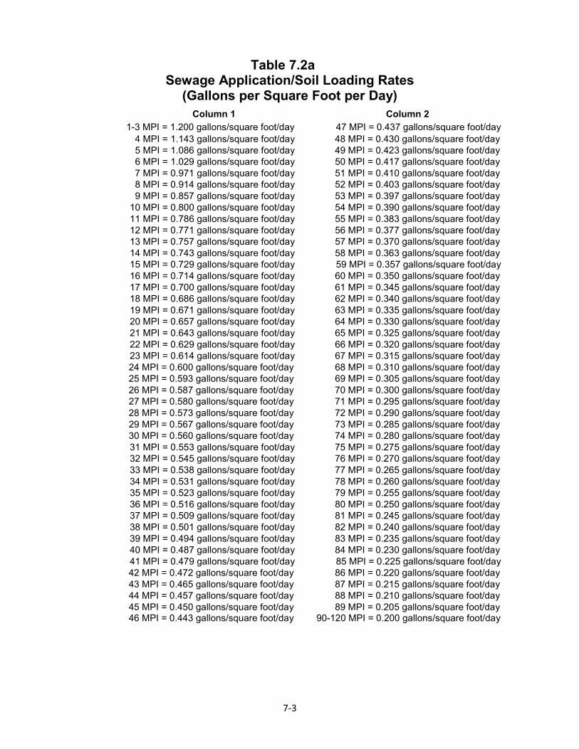
Table 7.2a Sewage Application/Soil Loading Rates
(Gallons per Square Foot per Day) Column 1 Column 2
1-3 MPI = 1.200 gallons/square foot/day 47 MPI = 0.437 gallons/square foot/day 4 MPI = 1.143 gallons/square foot/day 48 MPI = 0.430 gallons/square foot/day 5 MPI = 1.086 gallons/square foot/day 49 MPI = 0.423 gallons/square foot/day 6 MPI = 1.029 gallons/square foot/day 50 MPI = 0.417 gallons/square foot/day 7 MPI = 0.971 gallons/square foot/day 51 MPI = 0.410 gallons/square foot/day 8 MPI = 0.914 gallons/square foot/day 52 MPI = 0.403 gallons/square foot/day 9 MPI = 0.857 gallons/square foot/day 53 MPI = 0.397 gallons/square foot/day
10 MPI = 0.800 gallons/square foot/day 54 MPI = 0.390 gallons/square foot/day 11 MPI = 0.786 gallons/square foot/day 55 MPI = 0.383 gallons/square foot/day 12 MPI = 0.771 gallons/square foot/day 56 MPI = 0.377 gallons/square foot/day 13 MPI = 0.757 gallons/square foot/day 57 MPI = 0.370 gallons/square foot/day 14 MPI = 0.743 gallons/square foot/day 58 MPI = 0.363 gallons/square foot/day 15 MPI = 0.729 gallons/square foot/day 59 MPI = 0.357 gallons/square foot/day 16 MPI = 0.714 gallons/square foot/day 60 MPI = 0.350 gallons/square foot/day 17 MPI = 0.700 gallons/square foot/day 61 MPI = 0.345 gallons/square foot/day 18 MPI = 0.686 gallons/square foot/day 62 MPI = 0.340 gallons/square foot/day 19 MPI = 0.671 gallons/square foot/day 63 MPI = 0.335 gallons/square foot/day 20 MPI = 0.657 gallons/square foot/day 64 MPI = 0.330 gallons/square foot/day 21 MPI = 0.643 gallons/square foot/day 65 MPI = 0.325 gallons/square foot/day 22 MPI = 0.629 gallons/square foot/day 66 MPI = 0.320 gallons/square foot/day 23 MPI = 0.614 gallons/square foot/day 67 MPI = 0.315 gallons/square foot/day 24 MPI = 0.600 gallons/square foot/day 68 MPI = 0.310 gallons/square foot/day 25 MPI = 0.593 gallons/square foot/day 69 MPI = 0.305 gallons/square foot/day 26 MPI = 0.587 gallons/square foot/day 70 MPI = 0.300 gallons/square foot/day 27 MPI = 0.580 gallons/square foot/day 71 MPI = 0.295 gallons/square foot/day 28 MPI = 0.573 gallons/square foot/day 72 MPI = 0.290 gallons/square foot/day 29 MPI = 0.567 gallons/square foot/day 73 MPI = 0.285 gallons/square foot/day 30 MPI = 0.560 gallons/square foot/day 74 MPI = 0.280 gallons/square foot/day 31 MPI = 0.553 gallons/square foot/day 75 MPI = 0.275 gallons/square foot/day 32 MPI = 0.545 gallons/square foot/day 76 MPI = 0.270 gallons/square foot/day 33 MPI = 0.538 gallons/square foot/day 77 MPI = 0.265 gallons/square foot/day 34 MPI = 0.531 gallons/square foot/day 78 MPI = 0.260 gallons/square foot/day 35 MPI = 0.523 gallons/square foot/day 79 MPI = 0.255 gallons/square foot/day 36 MPI = 0.516 gallons/square foot/day 80 MPI = 0.250 gallons/square foot/day 37 MPI = 0.509 gallons/square foot/day 81 MPI = 0.245 gallons/square foot/day 38 MPI = 0.501 gallons/square foot/day 82 MPI = 0.240 gallons/square foot/day 39 MPI = 0.494 gallons/square foot/day 83 MPI = 0.235 gallons/square foot/day 40 MPI = 0.487 gallons/square foot/day 84 MPI = 0.230 gallons/square foot/day 41 MPI = 0.479 gallons/square foot/day 85 MPI = 0.225 gallons/square foot/day 42 MPI = 0.472 gallons/square foot/day 86 MPI = 0.220 gallons/square foot/day 43 MPI = 0.465 gallons/square foot/day 87 MPI = 0.215 gallons/square foot/day 44 MPI = 0.457 gallons/square foot/day 88 MPI = 0.210 gallons/square foot/day 45 MPI = 0.450 gallons/square foot/day 89 MPI = 0.205 gallons/square foot/day 46 MPI = 0.443 gallons/square foot/day 90-120 MPI = 0.200 gallons/square foot/day
7-4
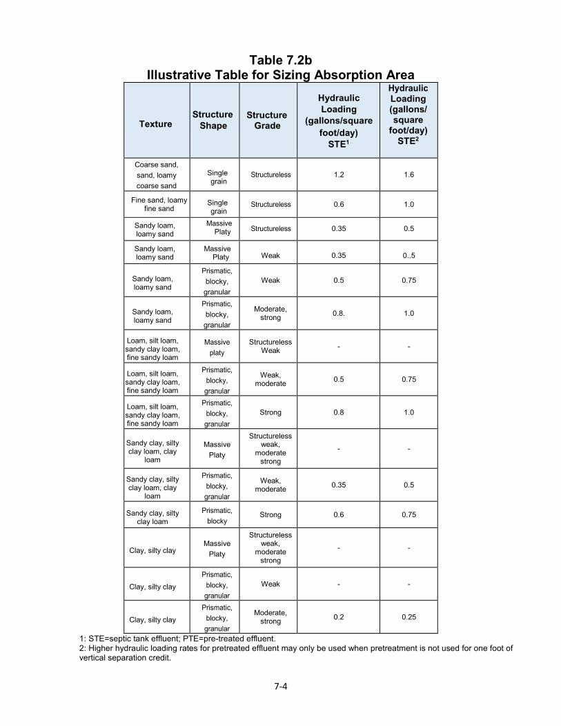
Table 7.2b Illustrative Table for Sizing Absorption Area
Texture Structure
Shape Structure
Grade
Hydraulic Loading
(gallons/square foot/day)
STE1
Hydraulic Loading (gallons/ square
foot/day) STE2
Coarse sand, sand, loamy coarse sand
Single grain
Structureless 1.2 1.6
Fine sand, loamy fine sand
Single grain
Structureless 0.6 1.0
Sandy loam, loamy sand
Massive Platy Structureless 0.35 0.5
Sandy loam, loamy sand
Massive Platy Weak 0.35 0..5
Sandy loam, loamy sand
Prismatic, blocky, granular
Weak 0.5 0.75
Sandy loam, loamy sand
Prismatic, blocky, granular
Moderate, strong 0.8. 1.0
Loam, silt loam, sandy clay loam, fine sandy loam
Massive platy
Structureless Weak - -
Loam, silt loam, sandy clay loam, fine sandy loam
Prismatic, blocky, granular
Weak, moderate 0.5 0.75
Loam, silt loam, sandy clay loam, fine sandy loam
Prismatic, blocky, granular
Strong 0.8 1.0
Sandy clay, silty clay loam, clay
loam
Massive Platy
Structureless weak,
moderate strong
- -
Sandy clay, silty clay loam, clay
loam
Prismatic, blocky, granular
Weak, moderate 0.35 0.5
Sandy clay, silty clay loam
Prismatic, blocky
Strong 0.6 0.75
Clay, silty clay Massive
Platy
Structureless weak,
moderate strong
- -
Clay, silty clay Prismatic,
blocky, granular
Weak - -
Clay, silty clay Prismatic,
blocky, granular
Moderate, strong 0.2 0.25
1: STE=septic tank effluent; PTE=pre-treated effluent. 2: Higher hydraulic loading rates for pretreated effluent may only be used when pretreatment is not used for one foot of vertical separation credit.
7-5
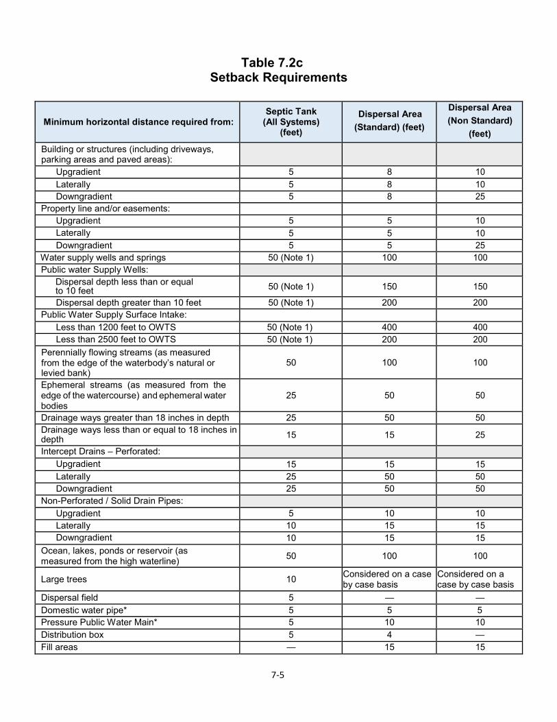
Table 7.2c Setback Requirements
Minimum horizontal distance required from: Septic Tank
(All Systems) (feet)
Dispersal Area (Standard) (feet)
Dispersal Area (Non Standard)
(feet) Building or structures (including driveways, parking areas and paved areas):
Upgradient 5 8 10 Laterally 5 8 10 Downgradient 5 8 25
Property line and/or easements:
Upgradient 5 5 10 Laterally 5 5 10 Downgradient 5 5 25
Water supply wells and springs 50 (Note 1) 100 100 Public water Supply Wells:
Dispersal depth less than or equal to 10 feet 50 (Note 1) 150 150
Dispersal depth greater than 10 feet 50 (Note 1) 200 200 Public Water Supply Surface Intake:
Less than 1200 feet to OWTS 50 (Note 1) 400 400 Less than 2500 feet to OWTS 50 (Note 1) 200 200
Perennially flowing streams (as measured from the edge of the waterbody’s natural or levied bank)
50 100 100
Ephemeral streams (as measured from the edge of the watercourse) and ephemeral water bodies
25 50 50
Drainage ways greater than 18 inches in depth 25 50 50 Drainage ways less than or equal to 18 inches in depth 15 15 25
Intercept Drains – Perforated: Upgradient 15 15 15 Laterally 25 50 50 Downgradient 25 50 50
Non-Perforated / Solid Drain Pipes: Upgradient 5 10 10 Laterally 10 15 15 Downgradient 10 15 15
Ocean, lakes, ponds or reservoir (as measured from the high waterline) 50 100 100
Large trees 10 Considered on a case by case basis
Considered on a case by case basis
Dispersal field 5 — — Domestic water pipe* 5 5 5 Pressure Public Water Main* 5 10 10 Distribution box 5 4 — Fill areas — 15 15
7-6
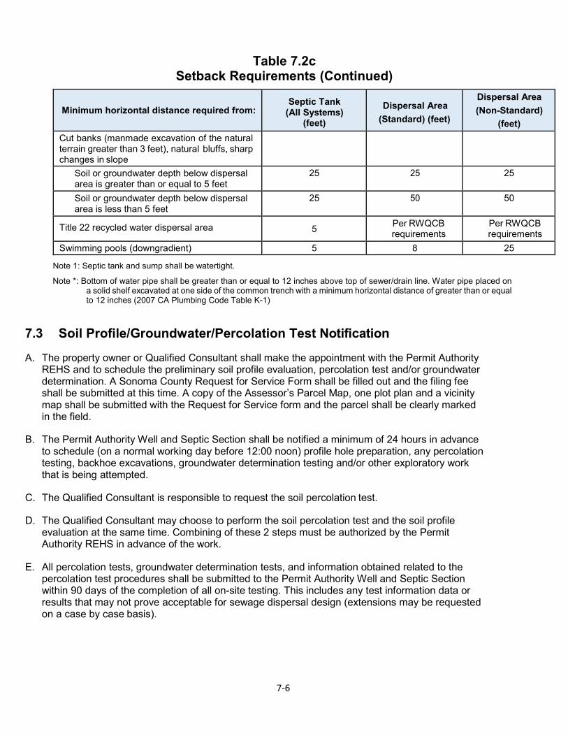
Table 7.2c Setback Requirements (Continued)
Minimum horizontal distance required from: Septic Tank
(All Systems) (feet)
Dispersal Area (Standard) (feet)
Dispersal Area (Non-Standard)
(feet) Cut banks (manmade excavation of the natural terrain greater than 3 feet), natural bluffs, sharp changes in slope
Soil or groundwater depth below dispersal area is greater than or equal to 5 feet
25 25 25
Soil or groundwater depth below dispersal area is less than 5 feet
25 50 50
Title 22 recycled water dispersal area 5 Per RWQCB requirements
Per RWQCB requirements
Swimming pools (downgradient) 5 8 25
Note 1: Septic tank and sump shall be watertight.
Note *: Bottom of water pipe shall be greater than or equal to 12 inches above top of sewer/drain line. Water pipe placed on a solid shelf excavated at one side of the common trench with a minimum horizontal distance of greater than or equal to 12 inches (2007 CA Plumbing Code Table K-1)
7.3 Soil Profile/Groundwater/Percolation Test Notification
A. The property owner or Qualified Consultant shall make the appointment with the Permit Authority REHS and to schedule the preliminary soil profile evaluation, percolation test and/or groundwater determination. A Sonoma County Request for Service Form shall be filled out and the filing fee shall be submitted at this time. A copy of the Assessor’s Parcel Map, one plot plan and a vicinity map shall be submitted with the Request for Service form and the parcel shall be clearly marked in the field.
B. The Permit Authority Well and Septic Section shall be notified a minimum of 24 hours in advance to schedule (on a normal working day before 12:00 noon) profile hole preparation, any percolation testing, backhoe excavations, groundwater determination testing and/or other exploratory work that is being attempted.
C. The Qualified Consultant is responsible to request the soil percolation test.
D. The Qualified Consultant may choose to perform the soil percolation test and the soil profile evaluation at the same time. Combining of these 2 steps must be authorized by the Permit Authority REHS in advance of the work.
E. All percolation tests, groundwater determination tests, and information obtained related to the percolation test procedures shall be submitted to the Permit Authority Well and Septic Section within 90 days of the completion of all on-site testing. This includes any test information data or results that may not prove acceptable for sewage dispersal design (extensions may be requested on a case by case basis).
7-7
7.4 Soil Profile Evaluations
A. Soil profile holes for the Preliminary Site Survey Soil Profile Evaluation typically are constructed prior to any soils percolation testing and/or groundwater determination tests.
1. Wet weather percolation testing and/or groundwater determination tests prior to soil profile evaluations are allowed; however, the tests are considered incomplete, pending approval of the soil profile investigation.
B. Profile holes must be adequately covered to prevent entrance if left unattended and backfilled immediately after completion of test procedures. Note: Work is permissible on sites to locate potentially acceptable areas prior to the preliminary evaluation.
C. Soil profiles holes are for the purpose of observing soil structures, texture, formations; the presence of seasonal groundwater; impervious rock formations, etc. Profiles are essential in the evaluation of any parcel for soil suitability for private sewage dispersal systems.
D. A minimum of two soil profile holes will be excavated with a backhoe. One soil profile hole shall be excavated in the primary effluent dispersal area and one soil profile hole in the reserve replacement area shall be required to demonstrate the suitability of soil conditions. Additional soil profile holes may be required to demonstrate suitable soil conditions for both the primary dispersal area and the reserve replacement area if the initial two profile holes show dissimilar conditions.
E. The profile holes shall be dug to a depth of at least 3 feet below the proposed absorption surface (trench bottom or 2 feet below the basal area of a mound).
1. Soil depth is measured vertically to the point where bedrock, hardpan, impermeable soils, rock content greater than 50 percent, or saturated soils are encountered.
2. For soils having less than 15 percent silt and clay, a minimum depth to groundwater below the leaching trench shall be 5 feet.
3. For soils having greater than 15 percent silt and clay, the minimum soil depth and depth to groundwater below the leaching trench shall be 3 feet.
a. Lesser soil depths may be granted only as a variance or for Non-Standard Alternative OWTS.
F. Augured profile holes are an acceptable alternative only (1) where use of a backhoe is impractical because of access, (2) when necessary to verify conditions expected on the basis of prior soils investigations, or (3) when done with geologic investigations (the extracted soils shall be arranged for evaluation so that corresponding depths can be determined). Where this method is employed, 3 profile holes in the primary area and 3 in the expansion area are required, (the same requirements as percolation test hole).
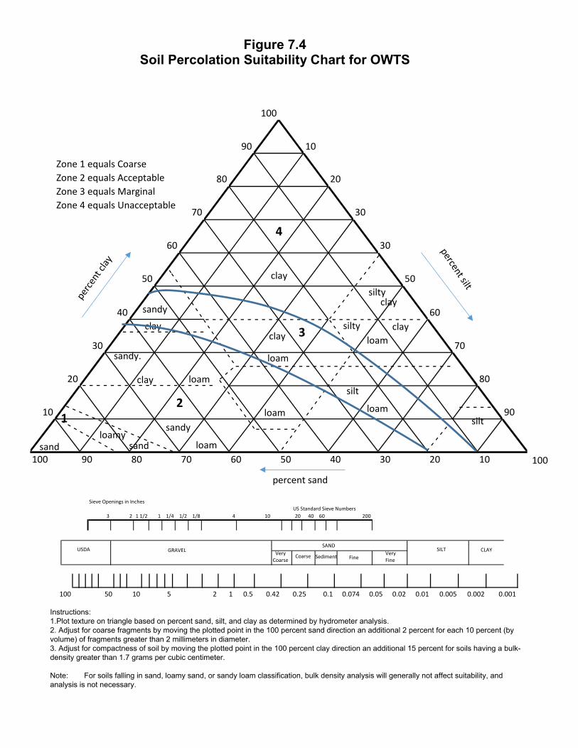
G. The classification of soils into zones as shown in the USDA Soils Classification Triangle will be the primary reference on acceptability of soils for OWTS. (see Figure 7.4)

7-8
H. The following factors are to be observed and reported from ground surface to a depth corresponding to the groundwater determination and soil percolation test requirements:
1. Thickness and coloring of soil layers, structure and texture using the United States Department of Agriculture (USDA) classification;
2. soil layer;
3. Depth to observed groundwater, saturated soil layers and areas of water infiltration;
4. Depth to soil mottling;
5. Other prominent soil features such as structure, stoniness, roots and pores, dampness, soil boundaries, etc.
100
90 10
80 20
70 30
60 30
50 50
40 60
30 70
20 80
10 90
100 90 80 70 60 50 40 30 20 10
4
clay
3
21
clay
clay
clay
clay
silt
silty
silty
sand
sandy
sandloamy
loam
loam loam
silt
sandy.
loam
loam
loamclay
sandy
- - - - -
- - - - - - - - - - - - - - - - - - -- - - - - - - - - - - - - - - - - - - - - - - - - - - - - - -
- - - - - - - - - - - -
- - - - - -
- - - - - - - - - - - - - - - - - - - - - - - - - - - - - - -
1
Zone 1 equals CoarseZone 2 equals AcceptableZone 3 equals MarginalZone 4 equals Unacceptable
percent sand
00
Sieve Openings in InchesUS Standard Sieve Numbers
3 2 1 1/2 1 1/4 1/2 1/8 4 10 20 40 60 200
USDA GRAVELSAND
SILT CLAYVery FineFine
Very Coarse
Coarse Sediment
100 50 10 5 2 1 0.5 0.42 0.25 0.1 0.074 0.05 0.02 0.01 0.005 0.002 0.001
Instructions:1.Plot texture on triangle based on percent sand, silt, and clay as determined by hydrometer analysis.2. Adjust for coarse fragments by moving the plotted point in the 100 percent sand direction an additional 2 percent for each 10 percent (byvolume) of fragments greater than 2 millimeters in diameter.3. Adjust for compactness of soil by moving the plotted point in the 100 percent clay direction an additional 15 percent for soils having a bulk-density greater than 1.7 grams per cubic centimeter.
Note: For soils falling in sand, loamy sand, or sandy loam classification, bulk density analysis will generally not affect suitability, and analysis is not necessary.
Figure 7.4 Soil Percolation Suitability Chart for OWTS
7-10
7.5 Groundwater Table Determination
A. General Provisions
Groundwater table determinations are required for lands having slopes of 0 to 5 percent in a basin area. Groundwater determinations on lands greater than 5 percent slope may be required if high seasonal groundwater is suspected.
B. Groundwater Table Determination Methods
Groundwater table determination can be made by one of following methods:
1. Direct observations via backhoe pits or auger holes;
2. Direct observation via existing water wells or monitoring wells;
3. Indirect observation via soil mottling; or
4. Compilation of approved readings or observations from any of the first three methods from adjacent or neighboring parcels and/or projects.
5. Other alternate methods as approved by the Permit Authority.
C. Direct Groundwater Table Determination Calendar
1. Direct groundwater table determinations shall be conducted between January 1 and March 1, after having received 50 percent of the average seasonal rainfall for each defined geographic area, as listed in Table 7.5 and depicted in Map 7.5, and within 10 days of receipt of 0.8 inch or more of rainfall within a 48-hour period as reported by the officially recognized reporting stations, as published in the Press Democrat.
2. Time extensions for direct groundwater table determinations may be authorized by the Permit Authority based on extended periods of rainfall before January 1 and/or after March 1.
D. Direct Groundwater Table Observation Construction Methods
1. Backhoe excavated profile holes shall remain open a minimum of 24 hours, adequately supervised or barricaded until observed by the Permit Authority REHS.
2. An alternative to leaving the holes open for 24 hours, is to insert a perforated pipe in the hole and place native backfill around the pipe (the backfill may not be compacted).
3. Another acceptable alternative is to hand dig or bore a hole to at least 36 inches below the proposed percolation test depth, insert a perforated pipe, and fill the annular space with gravel covered with 2 feet of native soil. This hole may then be used to monitor groundwater levels 24 or more hours later. Note: Additional holes at lesser depths to augment the data or prove multiple water table depths are encouraged, as is recordation of water levels throughout the wet-weather period.
4. Groundwater holes shall be protected to prevent sheet flow runoff, rainfall or other sources of non-groundwater from entering the observation hole.
7-11
5. The minimum depth to the anticipated highest level of groundwater that occurs over an extended period of time below the bottom of the leaching trench shall be determined according to soil texture and percolation rate. Where groundwater is determined to be non-usable, (for example cannot reasonably be expected to be used for withdrawal and beneficial use due to quantity and/or quality, a minimum depth to groundwater of 3 feet below the leaching trench bottom may be permitted without need for a variance, if soils contain greater than 15 percent silt and clay as demonstrated by hydrometer analysis, or soils having a percolation rate slower than 5 minutes per inch. This depth may be waived to no less than 2 feet if variance is justified or for an approved Non-Standard System.
E. Direct Groundwater Table Determination
1. The observation hole shall remain in place and undisturbed for a minimum of 24 hours to allow infiltration of groundwater.
2. Qualified Consultant shall measure and record the depth to groundwater from the undisturbed or pre-existing ground surface.
3. All observation holes shall be labeled and labelling shall be consistent with associated maps and/or submittals to the Permit Authority.
F. Indirect Groundwater Table Determination Method
1. Soil mottling observations may be utilized as an alternative to direct wet weather groundwater table determinations in the following circumstances:
a. Replacement dispersal systems. b. Soil characteristics, primarily the presence of iron and/or manganese, that lend themselves to
redoximorphic processes. c. If soil mottling is not observable to both the Qualified Consultant and the Permit Authority
staff, the client may elect to either conduct soil sampling for iron and/or manganese or pursue another groundwater elevation method.
d. Existing, legally established parcels.
2. Soil mottling observations shall not be utilized for properties with failed or canceled groundwater determinations on file.
3. A soil profile evaluation of sufficient means to determine the observable depth of soil mottling is required for this procedure.
4. Soil mottling shall be observed by the Qualified Consultant and Permit Authority staff. The field procedure will be similar to a Pre-Perc where the Qualified Consultant shall schedule a time to meet onsite with the Permit Authority staff and shall coordinate the excavation and backfilling of soil profile pits.
G. Compilation Method
The compilation method may be used provided the following criteria are met:
1. Soil profile readings or observations are within 500 feet of the proposed OWTS; and,
7-12
2. Area conditions lend themselves towards using off-site data or data not directly associated with the proposed OWTS. Area conditions include, but are not limited to, topography, slope, geology, geography, cut banks, natural bluffs, rock outcrops, landslides, springs, streams, roads; and,
3. Soil profile readings or observations were made by both a Qualified Consultant and the Permit Authority and site conditions have not changed to render the readings or observations invalid; and,
4. Soil profile readings or observations have been submitted and approved by the Permit Authority.
H. Conflicts Between Methods
Where a conflict in the above methods exists, the Permit Authority shall decide the appropriate method. Considerations shall include soil characteristics, rainfall and/or drought conditions, historical records and written reports.
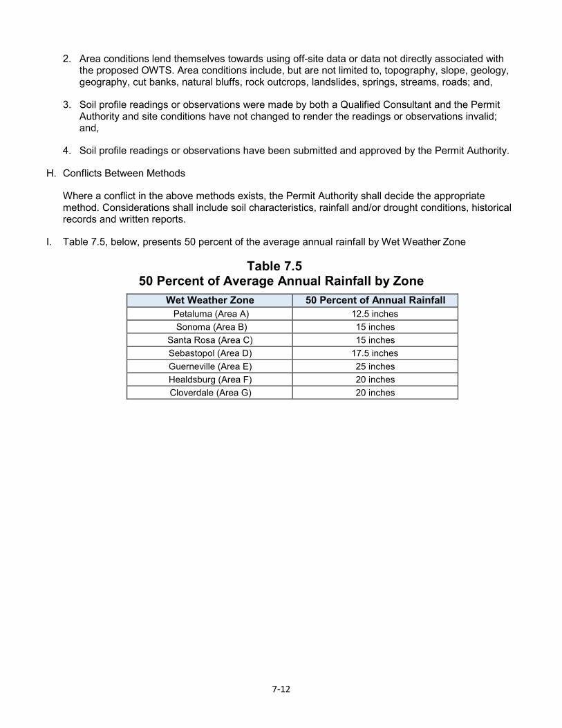
I. Table 7.5, below, presents 50 percent of the average annual rainfall by Wet Weather Zone
Table 7.5 50 Percent of Average Annual Rainfall by Zone
Wet Weather Zone 50 Percent of Annual Rainfall Petaluma (Area A) 12.5 inches Sonoma (Area B) 15 inches
Santa Rosa (Area C) 15 inches Sebastopol (Area D) 17.5 inches Guerneville (Area E) 25 inches Healdsburg (Area F) 20 inches Cloverdale (Area G) 20 inches
7-13
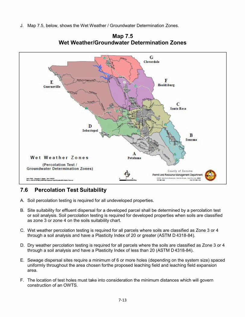
J. Map 7.5, below, shows the Wet Weather / Groundwater Determination Zones.
Map 7.5 Wet Weather/Groundwater Determination Zones
7.6 Percolation Test Suitability
A. Soil percolation testing is required for all undeveloped properties.
B. Site suitability for effluent dispersal for a developed parcel shall be determined by a percolation test or soil analysis. Soil percolation testing is required for developed properties when soils are classified as zone 3 or zone 4 on the soils suitability chart.
C. Wet weather percolation testing is required for all parcels where soils are classified as Zone 3 or 4 through a soil analysis and have a Plasticity Index of 20 or greater (ASTM D 4318-84).
D. Dry weather percolation testing is required for all parcels where the soils are classified as Zone 3 or 4 through a soil analysis and have a Plasticity Index of less than 20 (ASTM D 4318-84).
E. Sewage dispersal sites require a minimum of 6 or more holes (depending on the system size) spaced uniformly throughout the area chosen for the proposed leaching field and leaching field expansion area.
F. The location of test holes must take into consideration the minimum distances which will govern construction of an OWTS.

7-14
G. Additional requirements, determined on an individual basis, may be required for specially designed or non-standard on-site sewage dispersal systems when permitted.
7.7 Percolation Test Hole Construction
A. Percolation test hole construction requirements are as follows:
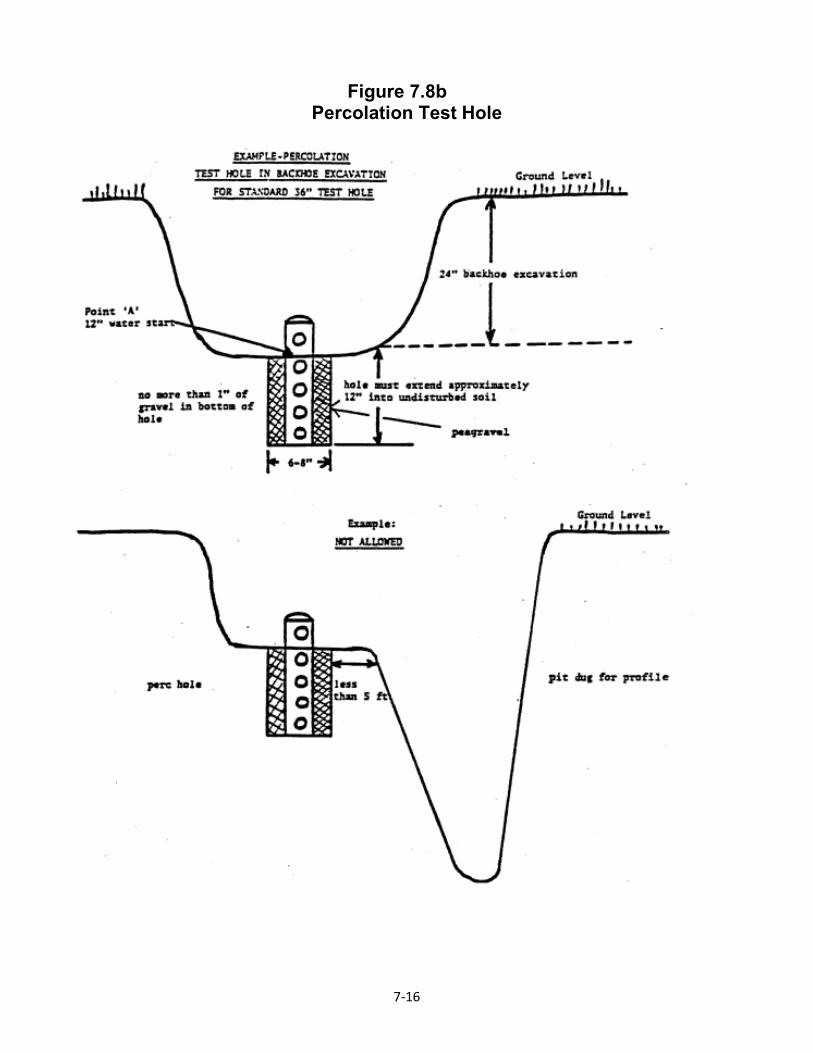
1. Dig or bore holes 4, 6, or 8 inches in diameter, to the vertical depth of the proposed trench and at least 12 inches below any proposed effluent pipe (refer to Tables 7.8a and b and Figures 7.8a and b).
2. After holes are dug, remove all loose material possible after carefully scraping the bottom and sides to remove any smeared soil surfaces. Add clean pea-gravel (maximum of 1 inch) to stabilize the hole, insert a perforated pipe (3 or 4 inch diameter) and place pea-gravel around exterior of pipe at least 12 inches, or up to ground surface. At the bottom of any backhoe excavations used, a secondary 6 or 8-inch diameter hole is to be bored to the depth of the proposed trench in undisturbed soil, providing that the depth shall not be less than 12 inches. Do not back fill soil around pipe in backhoe holes. Measure and record the length of the pipe on the report form.
Table 7.8a Percolation Test Hole Depth Requirement (Standard OWTS)
Standard OWTS Slope at Hole
Standard OWTS Depth of Holes
Standard 0 to 12.5 percent 1 30 inches (Minimum) Standard 12.5 to 30 percent 1 36 inches (Minimum) Filled Land (0 to 20 percent) 24 inches
Shallow Sloping (12.5 to 30 percent) 36 inches
1 Deeper percolation testing may be required if there is dissimilar soil types below the bottom of the trench.
Table 7.8b Percolation Test Hole Depth Requirement (Non-Standard OWTS)
Non-Standard OWTS Slope at Hole
Non-Standard OWTS Depth of Holes
Mound (0 to 20 percent) 24 inches (Minimum) STPD (0 to 20 percent) 24 inches (Minimum)
STPD (20 to 25 percent) 30 inches (Minimum) STPD (25 to 30 percent) 36 inches (Minimum)
STPD (up to 30 percent) 60 inches (Maximum) At-Grade 12, 24, and 36 inches
Drip Dispersal 6 to 12 inches and 24 inches below pipe depth
Shallow In Ground 10 to 14 inches and 24 inches below pipe depth
Gravel-less Pressurized Dispersal Channel (GPDC)
10 to 14 inches and 24 inches below pipe depth
7-15
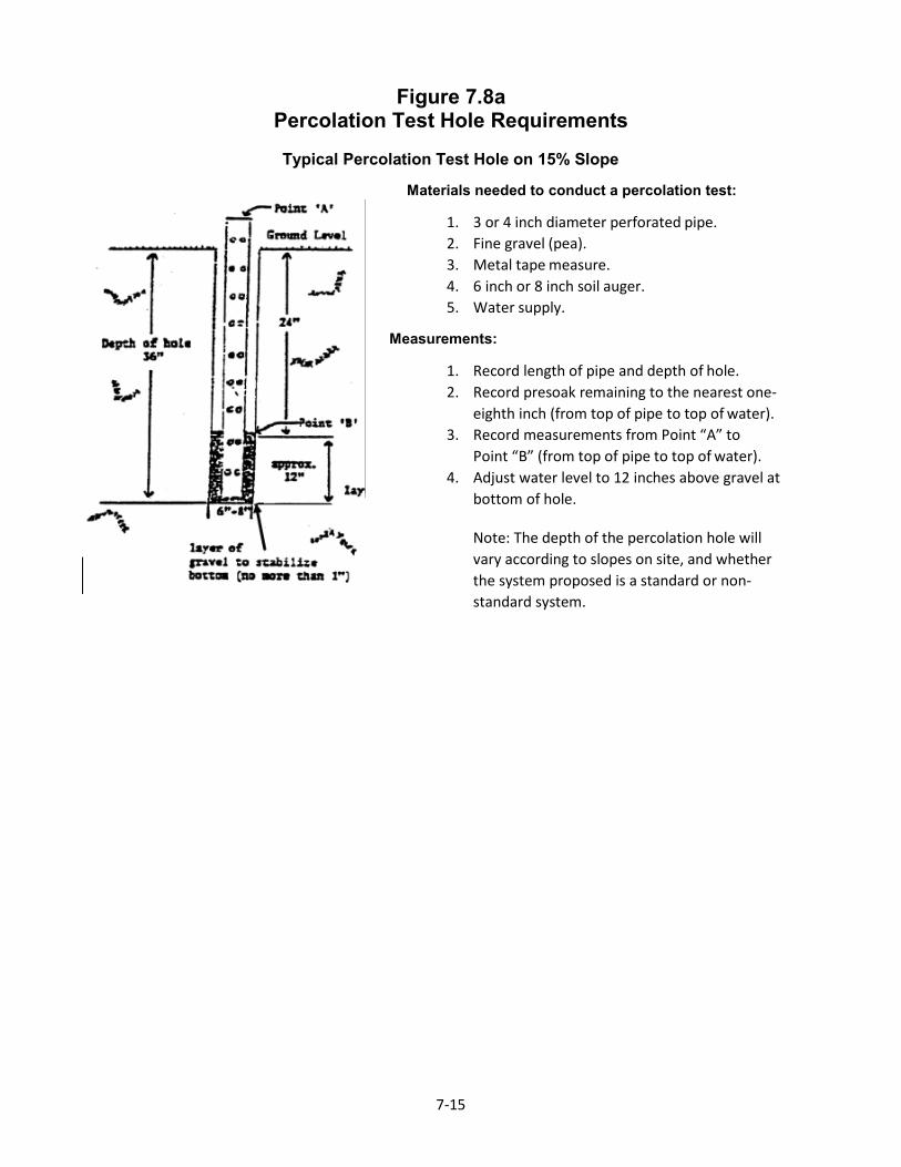
Figure 7.8a Percolation Test Hole Requirements
Typical Percolation Test Hole on 15% Slope
Materials needed to conduct a percolation test:
1. 3 or 4 inch diameter perforated pipe. 2. Fine gravel (pea). 3. Metal tape measure. 4. 6 inch or 8 inch soil auger. 5. Water supply.
urements:
1. Record length of pipe and depth of hole. 2. Record presoak remaining to the nearest one-
eighth inch (from top of pipe to top of water). 3. Record measurements from Point “A” to
Point “B” (from top of pipe to top of water). 4. Adjust water level to 12 inches above gravel at
bottom of hole.
Note: The depth of the percolation hole will vary according to slopes on site, and whether the system proposed is a standard or non-standard system.
Meas
7-16
Figure 7.8b Percolation Test Hole
7-17
7.8 Percolation Test Procedures
A. Presoak on the day prior to conducting the tests, fill the holes completely with clear water to which no substances have been added and refill at least 4 times. An alternate procedure is a continuous 12-hour presoaking employing a reservoir and continuous head device. Presoaking for wet- weather tests is not necessary if the tests are performed during the 10-day period in which wet- weather groundwater determinations are allowed.
B. Percolation Rate Measurements Percolation-rate measurements shall be made on the day following the presoaking of test holes.
1. When water remains from presoaking, record the inches of water remaining on the report form and adjust the water level to 12 inches over the gravel base. Measurements are then taken from a fixed point at the top of the pipe to the top of the water and like measurements taken each hour for 6 hours. Record measurements accurately, vertically, and to the nearest 1/8 inch.
2. When no water remains from presoaking, gently add clear water to the hole to a depth of 12 inches over the gravel base. Measure the drop in the water level from a fixed point at the top of the pipe to the top of the water each hour for 6 hours. Additional water may be added to 12 inches above the gravel when the hole is empty, or after any reading that indicates the water is less than 2 inches above the gravel. Record the new water elevation and continue measurements for duration of initial 6-hour test. Record measurements to the nearest 1/8 inch.
3. When hole is dry before the first 60 minutes upon start of test measurements, add clear water to 12 inches over the gravel base and take measurements every 10 minutes for 2 hours. The 12 inches of water is to be replaced at any time the hole is empty or the water depth is less than 2 inches.
7.9 Percolation Rate Interpretation
A. An average stabilized percolation rate of at least 1 inch per hour is required for the installation of a standard OWTS. Stabilized rates slower than 1 inch per hour or less than 1 minute per inch may be considered for inclusion within the Experimental or Alternative Non-Standard OWTS Program (Sections 12 and 13). Refer to Table 7.2a.
B. The drop in the water level that occurs between the 5th and 6th measurements on 6-hour tests is considered to be the stabilized percolation rate. The drop in water level that occurs between the 11th and 12th measurements is considered to be the stabilized rate for the 2-hour test. The readings during prior periods provide information for modification of the interpretation of the average stabilized percolation rate. Prior readings will be evaluated where refilling of test holes has occurred in the last 2 hours of the test or when rates show significant inconsistency during the course of the tests.
C. Average percolation rates less than 5 minutes per inch will require that a soil texture analysis (hydrometer method) be performed to determine the necessary clearance from proposed trench bottom to elevated seasonal water table, unless well logs demonstrate the distance to water table to be 40 feet or greater. If soil texture analysis is performed, required clearance to water table shall be as specified in Section 7.5.
D. An average percolation rate of less than 1 minute per inch is not suitable for the installation of an OWTS with the exception of a pretreatment and disinfection to a drip system.
7-18
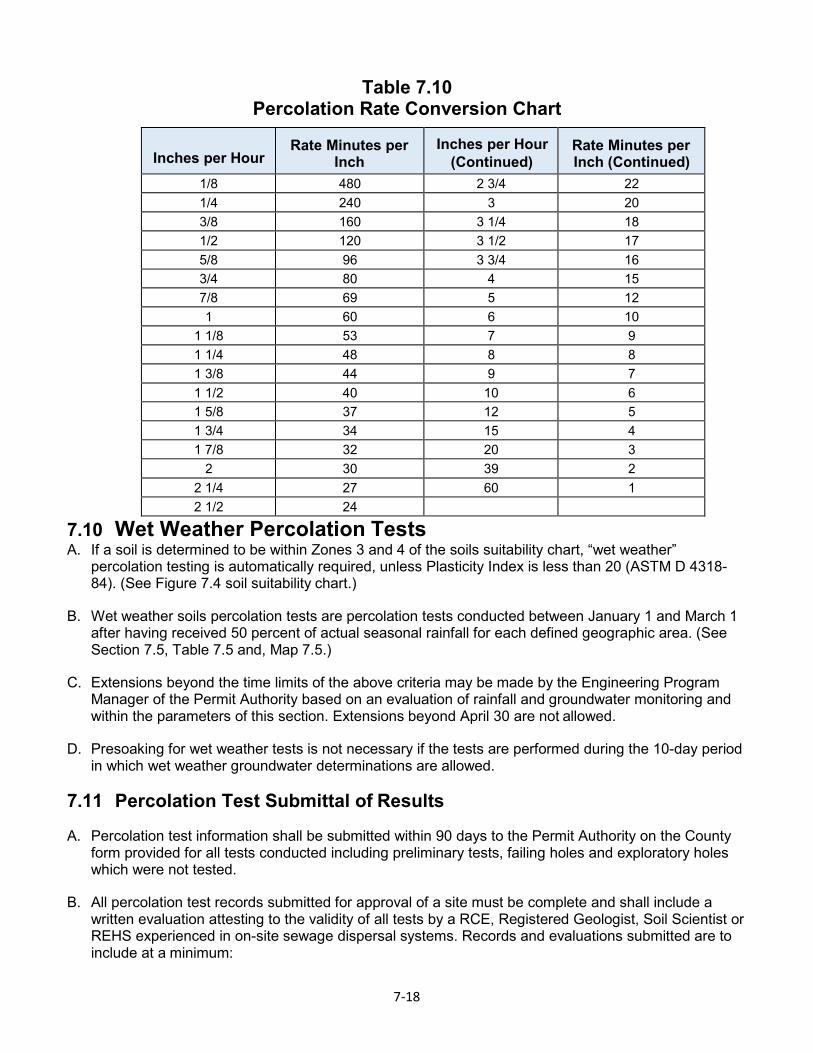
Table 7.10 Percolation Rate Conversion Chart
Inches per Hour Rate Minutes per
Inch Inches per Hour
(Continued) Rate Minutes per Inch (Continued)
1/8 480 2 3/4 22 1/4 240 3 20 3/8 160 3 1/4 18 1/2 120 3 1/2 17 5/8 96 3 3/4 16 3/4 80 4 15 7/8 69 5 12 1 60 6 10
1 1/8 53 7 9 1 1/4 48 8 8 1 3/8 44 9 7 1 1/2 40 10 6 1 5/8 37 12 5 1 3/4 34 15 4 1 7/8 32 20 3
2 30 39 2 2 1/4 27 60 1 2 1/2 24
7.10 Wet Weather Percolation Tests A. If a soil is determined to be within Zones 3 and 4 of the soils suitability chart, “wet weather”
percolation testing is automatically required, unless Plasticity Index is less than 20 (ASTM D 4318- 84). (See Figure 7.4 soil suitability chart.)
B. Wet weather soils percolation tests are percolation tests conducted between January 1 and March 1 after having received 50 percent of actual seasonal rainfall for each defined geographic area. (See Section 7.5, Table 7.5 and, Map 7.5.)
C. Extensions beyond the time limits of the above criteria may be made by the Engineering Program Manager of the Permit Authority based on an evaluation of rainfall and groundwater monitoring and within the parameters of this section. Extensions beyond April 30 are not allowed.
D. Presoaking for wet weather tests is not necessary if the tests are performed during the 10-day period in which wet weather groundwater determinations are allowed.
7.11 Percolation Test Submittal of Results
A. Percolation test information shall be submitted within 90 days to the Permit Authority on the County form provided for all tests conducted including preliminary tests, failing holes and exploratory holes which were not tested.
B. All percolation test records submitted for approval of a site must be complete and shall include a written evaluation attesting to the validity of all tests by a RCE, Registered Geologist, Soil Scientist or REHS experienced in on-site sewage dispersal systems. Records and evaluations submitted are to include at a minimum:
7-19
1. Data on all excavations, including failing holes and exploration holes within a 100-foot radius of the proposed septic area which were not tested.
2. Size of land area available for primary dispersal system and required replacement area, including a scaled plot plan showing the location of test holes dimensioned to property lines and delineating the area for the dispersal fields as calculated from the established percolation rate.
3. Accurate ground slope in the primary and expansion dispersal field, and areas within 50 feet.
4. Location of cut banks, natural bluffs and sharp changes in slope within 50 feet of the primary and expansion field.
5. Location of wells, springs, intercept drains, streams and other bodies of water on the property and within 150 feet of primary and expansion areas.
6. Location of existing houses, structures, rock outcrops and large trees in the area of the test.
7. Depth to groundwater when required, per Section 7.5.
8. Special area standards.
9. The person verifying the validity of the tests must describe the soils encountered in the profile holes as outlined in Section 7.4, as well as attest to the fact that required presoak was performed, that the test was set up in accordance with County standards, that he/she personally observed the site and a portion of the tests, and that it is a true and accurate indication of the suitability of the site for on-site sewage dispersal as measured by the standards of the Permit Authority and the County of Sonoma.
7.12 Cumulative Impact Studies
A. For OWTS greater than 1,500 gallons per day, cumulative impact studies may be required for those projects that propose a potential groundwater mounding and or nitrate loading condition that has potential to effect groundwater and/or surface waters.
B. The study may be required for subdivisions, commercial, multifamily and individual proposed OWTS.
C. The study shall be conducted by a qualified professional.
D. The study shall include both the detailed methodology used and the principles of groundwater hydraulics.
E. Groundwater Mounding Study shall be done to determine the highest extent the water table will rise during wet weather season.
F. Nitrate Loading Study shall include the annual chemical-water mass balance.
G. The cumulative study shall be conducted in accordance with the Ramlit Methodology.

7-20