oulu 2019 acta
TRANSCRIPT

UNIVERSITY OF OULU P .O. Box 8000 F I -90014 UNIVERSITY OF OULU FINLAND
A C T A U N I V E R S I T A T I S O U L U E N S I S
University Lecturer Tuomo Glumoff
University Lecturer Santeri Palviainen
Senior research fellow Jari Juuti
Professor Olli Vuolteenaho
University Lecturer Veli-Matti Ulvinen
Planning Director Pertti Tikkanen
Professor Jari Juga
University Lecturer Anu Soikkeli
Professor Olli Vuolteenaho
Publications Editor Kirsti Nurkkala
ISBN 978-952-62-2282-0 (Paperback)ISBN 978-952-62-2283-7 (PDF)ISSN 0355-3213 (Print)ISSN 1796-2226 (Online)
U N I V E R S I TAT I S O U L U E N S I SACTAC
TECHNICA
U N I V E R S I TAT I S O U L U E N S I SACTAC
TECHNICA
OULU 2019
C 708
Shahriar Shahabuddin
MIMO DETECTION AND PRECODING ARCHITECTURES
UNIVERSITY OF OULU GRADUATE SCHOOL;UNIVERSITY OF OULU, FACULTY OF INFORMATION TECHNOLOGY AND ELECTRICAL ENGINEERING;CENTRE FOR WIRELESS COMMUNICATIONS;INFOTECH OULU
C 708
ACTA
Shahriar Shahabuddin
C708etukansi.kesken.fm Page 1 Tuesday, May 7, 2019 1:30 PM


ACTA UNIVERS ITAT I S OULUENS I SC Te c h n i c a 7 0 8
SHAHRIAR SHAHABUDDIN
MIMO DETECTION AND PRECODING ARCHITECTURES
Academic dissertation to be presented with the assent ofthe Doctoral Training Committee of Technology andNatural Sciences of the University of Oulu for publicdefence in the OP auditorium (L10), Linnanmaa, on 26June 2019, at 12 noon
UNIVERSITY OF OULU, OULU 2019

Copyright © 2019Acta Univ. Oul. C 708, 2019
Supervised byProfessor Markku JunttiProfessor Christoph StuderProfessor Olli Silvén
Reviewed byProfessor Gerd AscheidProfessor Guillermo Payá Vayá
ISBN 978-952-62-2282-0 (Paperback)ISBN 978-952-62-2283-7 (PDF)
ISSN 0355-3213 (Printed)ISSN 1796-2226 (Online)
Cover DesignRaimo Ahonen
JUVENES PRINTTAMPERE 2019
OpponentProfessor Jarmo Takala
Shahabuddin, Shahriar, MIMO Detection and Precoding Architectures. University of Oulu Graduate School; University of Oulu, Faculty of Information Technology and Electrical Engineering; Centre for Wireless Communications; INFOTECH OuluActa Univ. Oul. C 708, 2019University of Oulu, P.O. Box 8000, FI-90014 University of Oulu, Finland
AbstractMultiple-input multiple-output (MIMO) techniques have been adopted since the third generation (3G) wireless communication standard to increase the spectral efficiency, data rate and reliability. The blessings of MIMO technologies for the baseband transceiver comes with the price of added complexity. Therefore, research on VLSI architectures for MIMO signal processing has generated a lot of interest over the past two decades. The advent of massive MIMO as a key technology for the fifth generation (5G) era also increased the interest in VLSI architectures related to MIMO communication research. In this thesis, we explored different VLSI architectures for MIMO detection and precoding algorithms. The detection and precoding are the most complex parts of a MIMO baseband transceiver. We focused on algorithm and architecture optimization and presented several VLSI architectures for MIMO detection and precoding.
The thesis proposed an application specific instruction-set processor (ASIP) for a multimode small-scale MIMO detector. In a single design the detector supports minimum mean-square error (MMSE), selective spanning with fast enumeration (SSFE) and list sphere detection (LSD). In addition, a multiprocessor architecture is proposed in this thesis for a lattice reduction (LR) algorithm. A modified Lenstra-Lenstra-Lovasz (LLL) algorithm is proposed for LR to reduce the complexity of the original LLL algorithm. We also propose a massive MIMO detection algorithm based on alternating direction method of multipliers (ADMM). The algorithm is referred to as ADMM based infinity norm (ADMIN) constrained equalization. The ADMIN detection algorithm is implemented as an application-specific integrated circuit (ASIC) and for field programmable gate array (FPGA). A multimode precoder ASIP is also proposed in this thesis. In a single design, the ASIP supports norm-based scheduling, QR-decomposition, MMSE precoding and dirty paper coding (DPC) based precoding.
Keywords: ASIP, MIMO, VLSI


Shahabuddin, Shahriar, MIMO-signaalien tunnistus- ja esikoodausarkkitehtuurit. Oulun yliopiston tutkijakoulu; Oulun yliopisto, Tieto- ja sähkötekniikan tiedekunta; Centre forWireless Communications; INFOTECH OuluActa Univ. Oul. C 708, 2019Oulun yliopisto, PL 8000, 90014 Oulun yliopisto
TiivistelmäMoni-tulo moni-lähtö (MIMO) -tekniikoita on sopeutettu kolmannen sukupolven (3G) langatto-masta viestintästandardista alkaen spektritehokkuuden, tiedonsiirtonopeuden ja luotettavuudenparantamiseksi. MIMO-teknologioilla on useita hyviä puolia suhteessa peruskaistan vastaanotti-meen, mutta samalla monimutkaisuus on lisääntynyt. VLSI-arkkitehtuurien tutkimus MIMO-signaalinkäsittelyssä on sen vuoksi herättänyt paljon kiinnostusta viimeisen kahden vuosikym-menen aikana. Myös MIMO:n saavuttama asema viidennen sukupolven (5G) viestintästandar-din pääteknologiana on lisännyt kiinnostusta VLSI-arkkitehtuureihin MIMO-viestinnän tutki-muksessa. Tässä tutkielmassa on tutkittu erilaisia VLSI-arkkitehtuureja MIMO-signaalien tun-nistus- ja esikoodausalgoritmeissa. Signaalien tunnistus ja esikoodaus ovat peruskaistaa käyttä-vän MIMO-vastaanottimen monimutkaisimmat osa-alueet. Tutkielmassa on keskitytty algoritmi-en ja arkkitehtuurien optimointiin ja esitetty useita VLSI-arkkitehtuureja MIMO-signaalien tun-nistusta ja esikoodausta varten.
Tutkielmassa on ehdotettu sovelluskohtaisen prosessorin (Application Specific Instruction-set Processor eli ASIP) käyttä pienen mittakaavan monimuotodetektorissa. Detektorin rakennetukee samanaikaisesti keskineliöpoikkeaman minimointia (MMSE), SSFE (Selective Spanningwith Fast Enumeration) -algoritmia ja LSD (List Sphere Detection) -algoritmia. Lisäksi tässä tut-kielmassa ehdotetaan monisuoritinarkkitehtuuria hilan redusointialgoritmille (Lattice Reductioneli LR). LR-algoritmia varten ehdotetaan muokattua Lenstra-Lenstra-Lovasz (LLL) -algoritmiavähentämään alkuperäisen LLL-algoritmin monimutkaisuutta. Lisäksi MIMO-signaalien tunnis-tusalgoritmin perustaksi ehdotetaan vuorottelevaa kertoimien suuntaustapaa Alternating Directi-on Method of Multipliers eli ADMM). ADMM-perustaisesta taajuusvasteen rajoitetusta ääretön-normi-korjauksesta (infinity norm constrained equalization) käytetään nimitystä ADMIN-algo-ritmi. ADMIN-tunnistusalgoritmi toteutetaan sovelluskohtaisena integroituna piirinä (Applicati-on-Specific Integrated Circuit eli ASIC) ohjelmoitavaa porttimatriisia (Field Programmable GateArray eli FPGA) varten. Lisäksi ehdotetaan ASIP-monimuotoesikooderin käyttöä. ASIP-esikoo-derin rakenne tukee normiperustaista aikataulutusta, QR-hajotelmaa, MMSE-esikoodausta jalikaisen paperin koodaukseen (Dirty Paper Coding eli DPC) perustuvaa esikoodausta.
Asiasanat: ASIP, MIMO, VLSI


Dedicated to my parents

8

Preface
The research for this thesis was conducted at the Centre for Wireless Communications -Radio Technology (CWC-RT) unit, University of Oulu, Finland. I would like to thankProfessor Matti Latva-Aho, Professor Ari Pouttu, the directors of CWC during my stayand and Dr. Harri Posti for giving me the opportunity to work in a world class researchenvironment.
I would like to express my sincere gratitude to my principal supervisor ProfessorMarkku Juntti for his constant support and guidance throughout my postgraduateresearch. I have been working in Professor Juntti’s group since the beginning of mymasters studies and his support and encouragement has a significant influence in myachievements. I would also like to thank Professor Christoph Studer from CornellUniversity, USA, for his patient guidance and supervision for this thesis. I am gratefulto Professor Studer for providing me the opportunity to work in his group at CornellUniversity. I would also like to thank Professor Olli Silvén for his supervision andtechnical guidance throughout this long journey. I would like to thank the reviewersof this thesis, Professor Gard Ascheid from RWTH Aachen University, Germany andProfessor Guillermo Payá Vayá from University of Hannovar, Germany. Their insightfulcomments helped me to improve this thesis. I would also like to thank Dr. Pekka Pirinenand Dr. Markus Myllylä for acting as members of my follow-up group.
The work of this thesis was carried out in Baseband and System Technologies forWireless Evolution (BaSE), Sensing, Compression, Communications and Data Fusionin Wireless Sensor Networks (SeCoFu), 5G Communication with a Heterogeneous,Agile Mobile network in the Pyeongchang wInter Olympic competitioN (5G Champion)and Academy of Finland 6Genesis Flagship projects. The funding for the projectswas provided by Academy of Finland, Finnish Funding Agency for Technology andInnovation - Tekes (currently known as Business Finland), Nokia, Renesas MobileEurope, Broadcom, Elektrobit/Bittium and Xilinx. I was privileged to receive personalgrants from Nokia Foundation, Oulu University Scholarship Foundation and TaunoTönningin säätiö. I am also grateful to University of Oulu Graduate School (UNIOGS)for providing me a travel grant.
I would like to thank the project managers Visa Tapio and Dr. Janne Janhunen. Iam very grateful to my colleagues in those projects, Dr. Essi Suikkanen, Dr. Johanna
9

Ketonen, Dr. Jarkko Huusko, Dr. Ganesh Venkatraman, Dr. Fatih Bayramoglu. I amalso thankful for the administrative support from Jari Sillanpää and Kirsi Outikangas. Inaddition, I would like to thank Dr. Jani Boutellier and Ilkka Hautala for their help in thisthesis. I would like to mention Dr. Zaheer Khan, Amanullah Ghazi, Dr. Ehsanul HaqueApu, Jahangir Alam, Julius Francis Gomes, Sadiqur Rahaman, Md Muksudul Alam andMuhammad Faijus Salehin, who helped me keep my sanity with their company duringthis journey. I would like to especially thank Dr. Ijaz Ahmad for his continued supportand great company. I would also like to thank my Nokia colleagues, Juha Yrjänäinen,Manish Gupta, and Saila Tammelin who have encouraged me during the past two yearsto complete my thesis.
Finally, I would like to express my gratitude to my family members. Special thanksgo to my siblings, Farzana Sharmin, Farhana Naznin and Md Shahanewaz Shahabuddin,for their love and support. I dedicate this thesis to my late father Shahabuddin Ahmedand my mother Jinnat Ara Begum who always tried to fulfill my demands no matter howunreasonable it was. I would like to express my gratitude to my loving wife Dr. FarahTazkera Rahman for tolerating me and being supportive in every aspect. I am grateful tothe Almighty Allah for fulfilling my dreams.
10

List of abbreviations
(·)−1 inverse‖ · ‖ 2-normλ wave lengthC set of complex numbersR set of real numbersZ set of integersxMMSE Estimated transmitted vector after MMSE detectionB basis of a latticeD diagonal matrixG Gramian matrixH MIMO channel matrixI identity matrixL lower triangular matrixm spanning vectorn noise vectorT unimodular matrixW precoding matrixx transmit symbol vectory Received symbol vectorCO convex polytope around O
L a complex valued latticeO constellation setΩ complex QAM constellationΠC orthogonal projection on set C
ρρρ signal-to-interference-plus-noise ratio (SINR) vectorℜ(·) real valuesσ2 noise varianceH MIMO augmented channel matrixQd Orthogonal matrixRd upper triangular matrix| · | absolute value
11

A areaB number of BS antennasc a constantEs symbol energyf (x) function of xMt Number of antennas in the transmitterN0 noise varianceNr Number of antennas in the receiverP total powerPdyn dynamic powerrASIP reconfigurable ASIPs scaling factorU number of users
1G first generation2G second generation3G third generation3GPP third generation partnership project3GPP2 third generation partnership project 24G fourth generation5G fifth generationACS add-compare-select unitALU arithmetic logic unitAMPS advanced mobile phone serviceASIC application-specific integrated circuitASIP application specific instruction-set processorsBP Belief propagationBS base stationCD coordinate descentCDMA code division multiple accessCG conjugate gradient methodCISC complex instruction set computerCLLL complex LLLCMAC complex multiply-and-accumulate unitCMUL complex multiplication
12

CSI channel state informationDFE decision feedback equalizationDPC dirty paper codingDSP digital signal processoreMBB enhanced mobile broadbandEPC evolved packet coreETSI European telecommunications standards instituteE-UTRAN evolved UTRANfcLLL fixed-complexity LLLFDD frequency-division duplexFFT fast Fourier transformFIFO first-in-first-outFIR finite impulse responseFPGA field programmable gate arrayFSE fixed sphere encoderFSM finite state machineFU function unitGCU global control unitGMRES generalized minimal residual methodGPP general purpose processorGPRS GSM packet radio systemsGSM global system for mobile communicationHDL hardware description languageHeNB home eNodeBHLS high level synthesisHOLL hardware-optimized LLLICI inter-channel interferenceILP instruction level parallelismISI inter-symbol interferenceITU-R international telecommunications union - radio communication sectorLAS likelihood ascent searchLDPC low-density parity checkLLL Lenstra-Lenstra-Lovasz algorithmLR lattice reductionLSD list sphere detection
13

LSU load-store unitLTE long term evolutionLTE-A LTE advancedLUT look-up tableMAP maximum a poteriori probabilityMCMC Markov chain Monte Carlo detectionMF matched filterMFU matched filter updateMIC multistage interference cancellationMIMO multiple-input multiple-outputMINRES minimal residual methodMLLL modified LLLMMSE minimum mean-square errorMTC machine type communicationMTSS multi-tree selective spanning detectionMUD multiuser detectorMU-MIMO multi user MIMONMT-400 Nordic Mobile TelephoneNTT Nippon Telephone and Telegraph CompanyOFDM orthogonal frequency-division multiplexingPER packet error-ratePIC parallel interference cancellationProDe processor design toolQPP quadratic permutation polynomialRF register fileRISC reduced instruction set computerRS-LLL reverse-siegel LLLRTL register transfer levelRTS Reactive tabu searchSC-FDMA single carrier frequency-division multiple accessSDM space-division multiplexingSDR semidefinite relaxationSFU special function unitSIC successive interference cancellationSIMO single-input multiple-output
14

SINR signal-to-interference-plus-noise ratioSMS short message servicesSOR successive over-relaxation methodSSFE selective spanning with fast enumerationSTBC space time block codesSU-MIMO single user MIMOTCE TTA-based codesign environmentTDD time-division duplexTDMA time division multiple accessTH Tomlinson-Harashima precodingTTA transport triggered architeturesTU typical urban channelUMTS universal mobile telephone serviceURLLC ultra-reliable low latency communicationV-BLAST vertical-Bell Laboratories layered space time architectureVLIW very long instruction wordVLSI very large scale integrationVM vector multiplication unitWCDMA wide-band CDMAZF zero-forcingZF-DPC zero-forcing DPC
15

16

List of original publications
This thesis is primarily based on the following original articles, which are referred to inthe text by their Roman numerals (I–VII):
I Shahabuddin, S., Hautala, I., Juntti, M., and Studer, C. (2018). ADMM-based Infinity NormDetection for Massive MIMO: Algorithm and VLSI Architecture, Journal Manuscript.
II Shahabuddin, S., Silvén, O., and Juntti, M. (February 2018). Programmable ASIPs forMultimode MIMO Transceiver, Journal of Signal Processing Systems.
III Shahabuddin, S., Silvén, O., and Juntti, M. (June 2017). ASIP design for Multiuser MIMOBroadcast Precoding, European Conference on Networks and Communications (EUCNC).
IV Shahabuddin, S., Juntti, M., and Studer, C. (May 2017). ADMM-based Infinity NormDetection for Large-Scale MIMO: Algorithm and VLSI Architecture, IEEE InternationalSymposium on Circuits and Systems, Maryland, USA.
V Shahabuddin, S., Janhunen, J., Ghazi, A., Khan, Z., and Juntti, M. (May 2015). ACustomized Lattice Reduction Multiprocessor for MIMO Detection, IEEE InternationalSymposium on Circuits and Systems, Lisbon, Portugal.
VI Shahabuddin, S., Janhunen, J., Suikkanen, E., Steendam, H., and Juntti, M. (June 2014). AnAdaptive Detector Implementation for MIMO-OFDM Downlink, International Conferenceon Cognitive Radio Oriented Wireless Networks (CROWNCOM), Oulu, Finland.
VII Shahabuddin, S., Janhunen, J., Juntti, M., Ghazi, A., and Silvén, O. (March 2014). Designof a transport triggered vector processor for turbo Decoding, Journal of Analog IntegratedCircuits and Signal Processing.
Papers I and IV are dedicated to a massive multiple-input multiple-output (MIMO)detection algorithm and its VLSI implementation. The algorithm and the initialimplementation results are proposed in conference Paper IV. The journal manuscript Ielaborates the implementation results. Paper V and part of Paper II are dedicated to acustomized processor implementation for MIMO detection. Paper III and part of Paper IIare dedicated to a customized processor implementation for MIMO precoding. Theupdated results of conference Papers III and V are jointly presented in journal Paper IIin the context of a transceiver. A customized multi-processor for lattice reduction ispresented in conference Paper of V. The customized processor design methodology ispresented in journal Paper VII.
17

18

Contents
AbstractTiivistelmäPreface 9List of abbreviations 11List of original publications 17Contents 191 Introduction 21
1.1 Evolution of wireless communications . . . . . . . . . . . . . . . . . . . . . . . . . . . . . . . . . 21
1.2 MIMO . . . . . . . . . . . . . . . . . . . . . . . . . . . . . . . . . . . . . . . . . . . . . . . . . . . . . . . . . . . . . . 22
1.3 Implementation methodologies for MIMO baseband algorithms . . . . . . . . . . 24
1.4 Objective of the thesis . . . . . . . . . . . . . . . . . . . . . . . . . . . . . . . . . . . . . . . . . . . . . . . . 26
1.5 Contributions of the thesis . . . . . . . . . . . . . . . . . . . . . . . . . . . . . . . . . . . . . . . . . . . . 27
2 Literature review 292.1 Small-scale MIMO detection . . . . . . . . . . . . . . . . . . . . . . . . . . . . . . . . . . . . . . . . . . 29
2.2 Massive MIMO detection . . . . . . . . . . . . . . . . . . . . . . . . . . . . . . . . . . . . . . . . . . . . . 32
2.2.1 Local search . . . . . . . . . . . . . . . . . . . . . . . . . . . . . . . . . . . . . . . . . . . . . . . . . . 32
2.2.2 Belief propagation detectors . . . . . . . . . . . . . . . . . . . . . . . . . . . . . . . . . . . . 33
2.2.3 Approximate inversion based linear detectors . . . . . . . . . . . . . . . . . . . . .33
2.3 MIMO precoding . . . . . . . . . . . . . . . . . . . . . . . . . . . . . . . . . . . . . . . . . . . . . . . . . . . . 37
2.4 TTA designs . . . . . . . . . . . . . . . . . . . . . . . . . . . . . . . . . . . . . . . . . . . . . . . . . . . . . . . . .38
3 Summary of the original publications 433.1 ASIP design for small-scale adaptive MIMO detection . . . . . . . . . . . . . . . . . . . 43
3.1.1 Background . . . . . . . . . . . . . . . . . . . . . . . . . . . . . . . . . . . . . . . . . . . . . . . . . . . 43
3.1.2 System model . . . . . . . . . . . . . . . . . . . . . . . . . . . . . . . . . . . . . . . . . . . . . . . . . 43
3.1.3 Detection Schemes . . . . . . . . . . . . . . . . . . . . . . . . . . . . . . . . . . . . . . . . . . . . 43
3.1.4 Error-rate performance . . . . . . . . . . . . . . . . . . . . . . . . . . . . . . . . . . . . . . . . . 45
3.1.5 Detector ASIP . . . . . . . . . . . . . . . . . . . . . . . . . . . . . . . . . . . . . . . . . . . . . . . . 45
3.1.6 Comparison . . . . . . . . . . . . . . . . . . . . . . . . . . . . . . . . . . . . . . . . . . . . . . . . . . . 47
3.2 A multiprocessor design for lattice reduction . . . . . . . . . . . . . . . . . . . . . . . . . . . 49
3.2.1 Background . . . . . . . . . . . . . . . . . . . . . . . . . . . . . . . . . . . . . . . . . . . . . . . . . . . 49
3.2.2 Lattice reduction . . . . . . . . . . . . . . . . . . . . . . . . . . . . . . . . . . . . . . . . . . . . . . 49
19

3.2.3 Modified LLL algorithm . . . . . . . . . . . . . . . . . . . . . . . . . . . . . . . . . . . . . . . 513.2.4 TTA multiprocessor for MLLL . . . . . . . . . . . . . . . . . . . . . . . . . . . . . . . . . 533.2.5 Comparison . . . . . . . . . . . . . . . . . . . . . . . . . . . . . . . . . . . . . . . . . . . . . . . . . . . 54
3.3 ASIC and FPGA design for massive MIMO detection . . . . . . . . . . . . . . . . . . . 563.3.1 Background . . . . . . . . . . . . . . . . . . . . . . . . . . . . . . . . . . . . . . . . . . . . . . . . . . . 563.3.2 System model . . . . . . . . . . . . . . . . . . . . . . . . . . . . . . . . . . . . . . . . . . . . . . . . . 563.3.3 ADMIN: ADMM-based infinity norm detection . . . . . . . . . . . . . . . . . . 573.3.4 LDL-Decomposition based Soft-output ADMIN . . . . . . . . . . . . . . . . . . 593.3.5 VLSI architecture . . . . . . . . . . . . . . . . . . . . . . . . . . . . . . . . . . . . . . . . . . . . . 623.3.6 FPGA implementation . . . . . . . . . . . . . . . . . . . . . . . . . . . . . . . . . . . . . . . . . 643.3.7 ASIC implementation . . . . . . . . . . . . . . . . . . . . . . . . . . . . . . . . . . . . . . . . . . 65
3.4 ASIP design for small-scale MIMO precoding . . . . . . . . . . . . . . . . . . . . . . . . . . 693.4.1 Background . . . . . . . . . . . . . . . . . . . . . . . . . . . . . . . . . . . . . . . . . . . . . . . . . . . 693.4.2 System Model . . . . . . . . . . . . . . . . . . . . . . . . . . . . . . . . . . . . . . . . . . . . . . . . .693.4.3 Precoding schemes . . . . . . . . . . . . . . . . . . . . . . . . . . . . . . . . . . . . . . . . . . . . 703.4.4 Precoder ASIP . . . . . . . . . . . . . . . . . . . . . . . . . . . . . . . . . . . . . . . . . . . . . . . . 723.4.5 Comparison . . . . . . . . . . . . . . . . . . . . . . . . . . . . . . . . . . . . . . . . . . . . . . . . . . . 73
4 Conclusion and future work 75References 79Original publications 91
20

1 Introduction
1.1 Evolution of wireless communications
Wireless communication technology is an indispensable part of modern society. We livein a world of wireless connectivity that encompasses basic home internet services tosophisticated machine-to-machine communication used in the robotics industry. Theblessing of wireless communication provides us remote internet access and enhancesour mobility tremendously. We have greater access to information than ever before andit is all possible due to the advancements and inventions of wireless technologies. Thefirst generation (1G) wireless technology was primarily developed for voice service.The world’s first commercial cellular network was implemented by Japan’s NipponTelephone and Telegraph Company (NTT) in 1979. Nordic Mobile Telephone (NMT-400) is a system developed in 1981 that supports international roaming and automatichandover [1]. The most successful 1G technology was advanced mobile phone service(AMPS) which was first implemented by AT&T and Bell Labs for commercial use in1983. The advancement of computational platforms and microwave devices motivatedthe development of second generation (2G) wireless systems. Contrary to the analogschemes used in 1G, the 2G systems adopted digital communications to increase theefficiency of limited frequency bands [2, 3]. 2G made digitized services like shortmessage services (SMS) possible. The European telecommunications standards institute(ETSI) developed a 2G technology called global system for mobile communication(GSM) that was later accepted outside Europe [1]. Time division multiple access(TDMA) is used in GSM with a capability of multiplexing eight users in a single200 KHz channel bandwidth. GSM packet radio systems (GPRS) was introduced byETSI during the mid-90s to provide internet services to users alongside voice and SMSservices. Code division multiple access (CDMA) was the other dominant 2G technologythat was first proposed by Qualcomm in 1989 [4]. Unlike GSM, multiple users couldshare the same frequency band and were separated by a unique orthogonal spreadingcode assigned to each of them.
The primary goal for third generation (3G) wireless systems was to provide higherdata rates compared to 2G [5]. Universal mobile telephone service (UMTS) wasoriginally proposed by ETSI as a 3G system [6]. In 1998, third generation partnershipproject (3GPP) was formed as a collaboration of six regional telecommunication
21

standards bodies to continue the development of UMTS. In 1999, 3GPP published thefirst 3G UMTS standards, which is also known as UMTS release 99. UMTS inheritedthe basic network architecture of GSM. However, the air interface of UMTS, calledwide-band CDMA (W-CDMA), was built on the basic features of CDMA. The 3Gversion of the CDMA systems was called CDMA2000. The third generation partnershipproject 2 (3GPP2) took responsibility of official standardization process of CDMA2000[7].
Release 10 from 3GPP, which is commonly known as long term evolution advanced(LTE-A), fulfills the requirements of the fourth generation (4G) standard that wasspecified by the international telecommunications union - radio communication sector(ITU-R) [44]. LTE-A network has two major parts; evolved packet core (EPC) andevolved UTRAN (E-UTRAN). The EPC is an all IP and packet switched backbonenetwork. The LTE-A system supports non-3GPP access networks. LTE-A systems alsostandardized new entities and applications such as machine type communication (MTC),home eNodeB (HeNB) or femtocells and relay nodes.
The standardization of fifth generation (5G) wireless communication is still atan early phase. The key enablers of the 5G wireless system are enhanced mobilebroadband (eMBB), massive MTC and ultra-reliable low latency communication(URLLC) technologies. The 5G standard proposed high carrier frequencies (for example,28 GHz or 39 GHz) in addition to traditional sub-6 GHz carriers. The network layer of5G adopted novel techniques like network slicing, virtualization and edge computing.To support tens of Gigabits for the eMBB of 5G, the multiple-input multiple-output(MIMO) technologies will play a crucial role.
1.2 MIMO
MIMO is a key technology to increase the capacity of wireless transmission andreception. Instead of using a single antenna for transmission or reception, severalantennas are used in a MIMO transceiver to improve system capacity. Paulraj andKailath filed a patent in 1993 that proposed a technique for increasing data rates bysplitting a high-rate signal and transmitting though spatially separated transmittersand recovering using a receive antenna array based on different angles of arrival [8].This patent is now considered as one of the earliest inventions that lead to the currentMIMO technology. MIMO exploits the radio propagation phenomenon called multipathwhere radio signals reach the receiver antenna multiple times at different angles and
22

times. MIMO uses multiple antennas at both sides to add a spatial dimension to improveperformance and range. MIMO systems increase data throughput and link range withoutadditional bandwidth [9]. Due to the benefits, MIMO systems have been adopted inmost popular wireless technologies.
MIMO signaling techniques can be categorized in two main factions: space-timediversity coding and spatial multiplexing. The space-time diversity coding extracts fullspatial diversity through appropriate construction of space-time code words. A simplediversity coding technique was proposed by Alamouti for two transmit antennas that canachieve full diversity [10]. A generalization of the Alamouti scheme is called space-timeblock codes (STBC) that provides full diversity for an arbitrary number of antennas [11].The spatial multiplexing techniques, as opposed to the diversity techniques, aims atmaximizing transmission rates. The idea is to divide the transmit data into parallel layersof data streams and transmit over different antennas to increase data rates. One exampleof such type of MIMO systems is the vertical-Bell Laboratories layered space time(V-BLAST) architecture [12].
In a traditional small-scale MIMO system, two to four antennas were used on bothsides of the communication link. In other words, a single multi-antenna transmittercommunicates with a single multi-antenna receiver, which is also called single userMIMO (SU-MIMO). The multiuser MIMO (MU-MIMO) is a type of MIMO wherethe transmitter and receiver both can contain single or multiple antennas. MU-MIMOtechniques are typically employed for a base station (BS) with multiple antennas thatserves several users with single or multiple antennas [13, 14]. The total number ofantennas on the transmitter and receiver side are equal in a MU-MIMO system and thenumber is less than ten.
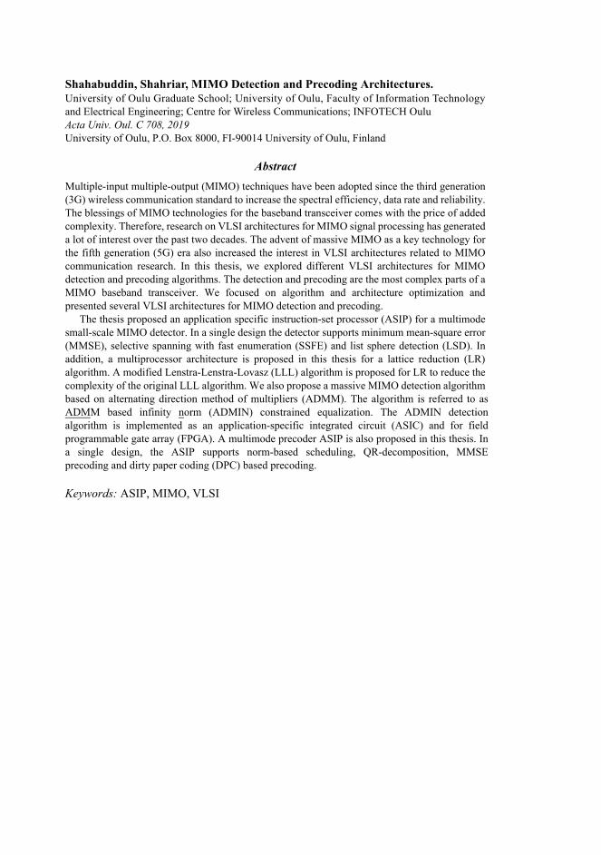
Massive MU-MIMO is another advanced MIMO technology where the BS stationsemploys tens or hundreds of antennas to serve tens or hundreds of users [15, 16]. As thenumber of antennas grows towards infinity, random matrix theory demonstrates that theeffects of uncorrelated noise and small-scale fading are diminished and the number ofusers per cell become independent on the size of the cell [17]. The massive MIMOsystem is mainly designed for time-division duplex (TDD) systems to exploit channelreciprocity while the small-scale MU-MIMO can exploit both TDD and frequency-division duplexing (FDD). A typical massive MIMO system is depicted in Fig. 1 wherea BS with several antennas are serving several single antenna users.
23

Channely = Hx+n
Fig. 1. Massive MIMO system: A BS transmitter with numerous antennas serving numeroususers.
1.3 Implementation methodologies for MIMO baseband algorithms
Any MIMO baseband algorithm can be designed with a high level language andimplemented on a general purpose processor (GPP). However, GPP is not optimalfor any particular application. GPP is not suitable for high speed applications likeMIMO baseband algorithms. Digital signal processors (DSP) are designed specificallyto support signal processing applications [18]. DSPs consist of a lot of repeated partsand are designed to support complex arithmetic operations. However, DSPs are alsonot sufficient for most of the high speed baseband algorithms of recent generations ofcommunications. The DSPs still can be used for communication systems with low datarates or older generation communications.
Digital very large scale integration (VLSI) implementation provides high throughputand low power consumption. Unlike the software implementation on GPP and DSP, thedigital VLSI based hardware design can be used for high data requirements [19]. Thereare different design methods and implementation platforms for digital VLSI. The mostpopular platforms to implement digital VLSI are application-specific integrated circuits(ASIC) and field programmable gate arrays (FPGA) [20, 21]. ASICs are generally mostpower-efficient and provides the highest throughput. Therefore, complex basebandalgorithms have been typically implemented as an ASIC which works in parallel with abigger design. ASICs can be the cheapest solution if the production volume is high.The drawback of an ASIC is the complexity of the hardware design. Besides, it canbe costly and not feasible for a small volume of production. The biggest drawback is
24

the complete inflexibility of ASICs. It is not possible to change an MIMO basebandASIC for updates or bug fixes [20]. If the production volume is small, FPGA can be analternative solution. The FPGAs can provide significantly higher throughput than DSPimplementation because they map the digital VLSIs. It is also possible to reconfigureand apply bug fixes on FPGAs. However, FPGAs can also be a costly solution when theproduction volume required is very high. Unlike ASIC designs, FPGA implementationsare also limited by FPGAs’ highest clock frequency [21].
The typical method to design a finite state machine (FSM) based register transfer level(RTL) digital VLSI is to use a handwritten hardware description language (HDL) [22].A designer can accurately map the functionalities of an algorithm with HDLs. Therefore,the design can reach high clock frequency and throughput. However, as the basebandalgorithms are getting increasingly complex, the verification process of the HDL imposesa significant challenge for the time-to-market requirement. The high level synthesis(HLS) tools where a high level programming language such as C or C++ can be directlyused to generate HDLs are becoming increasingly popular [23]. The HLS tools forASICs and FPGAs can provide approximately 80%−90% of a HDL design in terms ofclock frequency and throughput. Besides, the verification process can be simpler as thetest benches are generated by the tool itself.
Application specific instruction-set processors (ASIP) is another method of designingdigital VLSI for baseband applications [19]. An ASIP can be viewed as a customizedprocessor which is tailored for a particular application or algorithms. The ASIP designtools typically enables the designer to add custom instructions for different operations.The custom instructions can be used for operations such as complex arithmetic, non-standard floating point arithmetic, an adder for three numbers or other operations thatcan accelerate the target algorithm. Besides reducing latency with custom operations, thedesigner can remove unnecessary operations to increase the overall clock frequency of anASIP. ASIPs achieve higher performance than DSPs by the use of customized functionunits. On the other hand, ASIPs are more flexible than the handwritten RTL designsdue to the use of high level language as firmware [24]. Typically, ASIPs use very longinstruction word (VLIW) and transport triggered (TTA) architectures. The conventionalreduced instruction set computer (RISC) or complex instruction set computer (CISC)executes instructions sequentially and thus, they are not suitable for high speed digitalsignal processing [19]. VLIW and TTA are based on instruction level parallelism (ILP)property where several instructions can be executed during each clock cycle [25].
25

1.4 Objective of the thesis
The thesis mainly focuses on communication systems below 6 GHz. The radio spectrumis a limited resource on carrier frequencies below 6 GHz. MIMO techniques aim toefficiently utilize the available spectrum with the price of added complexity due to thenature of signal processing algorithms in the baseband. In other words, the efficientuse of the spectrum requires sophisticated MIMO transceiver algorithms and theiraccurate realization. There exist several phases from the theoretical framework of thealgorithms to their feasible implementations. These steps are algorithm development,floating point simulation, word length analysis, architecture exploration, RTL designand RTL verification. These steps are divided among several engineers in a typicalindustrial setup. However, the joint design of algorithm and architecture can result in themost efficient realizations. For example, a minor change in the algorithm can lead toa dramatic improvement in the implementation in many cases. Joint algorithm andarchitecture optimization for efficient implementation of MIMO baseband algorithmswas the first aim of the thesis.
The primary aim of the thesis was to explore different digital VLSI architecturesfor MIMO baseband systems. Small-scale MIMO architectures have been developedover the last two decades. Customized processors are also explored for different signalprocessing algorithms as an alternative to conventional VLSI. We take a differentapproach and design customized processors for several MIMO transceiver algorithms.The author argues that a customized processor for a single algorithm does not providesubstantial benefit over the traditional VLSI design. A customized processor for severalalgorithms might be a better choice than designing several RTL designs. The customizedprocessors heavily rely on special function units (SFUs) which are designed with HDL.In that respect, the design can be viewed as a VLSI architecture where a part of the datapath is designed with HDL and the control path is generated with the processor designtool. We also explore multiprocessor architecture for MIMO preprocessing. The otheraim of the thesis was to develop a novel detection algorithm and architecture for massiveMIMO. Instead of using a customized processor, the aim was to apply traditional RTLdesigns with handwritten VHDL. The thesis work demonstrates the applicability ofdifferent VLSI design methods with a usage case and provides an insight on how todesign a VLSI architecture.
26

1.5 Contributions of the thesis
The thesis is based on seven publications where the author was the main contributor.The author developed the main ideas, designs and results in them. The other authorshelped the first author with their comments and guidance with the exceptions explainedbelow. The contributions of the thesis can be summarized in the following way:
1. Design of a multimode detector ASIP (Paper II and VI).2. Design of a multiprocessor for lattice reduction (Paper V)3. Massive MIMO detection algorithm and VLSI architecture (Paper I and IV)4. Multimode precoder ASIP (Paper II and III)5. Review of the design flow of TTA ASIP (Paper VII)
Paper I and parts of paper VI presents a TTA ASIP for multimode MIMO detection. Themultimode implementation supports minimum mean square error (MMSE) detection,K-best list sphere detection (LSD) and selective spanning with fast enumeration (SSFE)detection. The first author developed the architecture in the TCE environment, generatedthe VHDL and conducted the synthesis trials with Synopsis design compiler. Theslicer function unit was developed by Dr. Janne Janhunen which is presented in hiswork [26]. The long term evolution (LTE) simulator used for the error-rate analysis wasimplemented by Dr. Nenad Veselinovic, Dr. Mikko Vehkaperä and Dr. Markus Myllylä.The typical urban channel models were developed by Dr. Esa Kunnari.
Paper V presents a multiprocessor system for lattice reduction. In this work, theauthor presents an algorithm for lattice reduction. A hard output simulator is developedfor this work which is based on Dr. Christoph Studer’s simple MIMO simulatorframework. Several key ideas of the work are taken from Pirkka Silvola and Dr. XiaoxiaLu’s work on lattice reduction. The first author developed and simulated the algorithmin the hard output simulator. The multiprocessor architecture is also developed andsynthesized by the first author himself.
Papers I and IV presents a massive MIMO detection algorithm. The algorithmwas developed by the author during his visit to Dr. Christoph Studer’s lab in CornellUniversity. A novel detection method based on a popular convex optimization methodfor massive MIMO is presented by the author. A soft output MIMO-OFDM Matlabsimulator is used for this work which was developed by Dr. Christoph Studer’s group.The RTL design was developed and verified by the author. The synthesis for 16×16was carried out by the author. The placement and routing with Cadence SoC Encounter
27

was done by Ilkka Hautala. The FPGA synthesis and implementation results werecarried out by the first author himself.
Papers II and III present a TTA ASIP that supports two algorithms for MIMOprecoding on the transmitter. The ASIP can also support norm-based scheduling andQR decomposition. The first author developed the MMSE precoder based on QR-decomposition on a augmented channel matrix and simulated in a hard output Matlabsimulator. The simulator was developed by the author to compare the performance ofthe precoders. The performance of the schedulers are based on a simulator developedby Dr. Ganesh Venkatraman. The first author developed the TTA ASIP in the TCEenvironment, generated the VHDL and conducted the synthesis trials with Synopsisdesign compiler.
The review of a TTA ASIP design flow is summarized in Paper VII. The authorsshow each step of a TTA processor design with the aid of the processor designer tool,hardware database and cycle accurate simulator to estimate the latency. The authors useturbo decoding as a use case to demonstrate how efficiently TCE can be used to designASIPs for signal processing algorithms. The results related to the turbo decoder ASIPare outside the scope of this thesis.
28

2 Literature review
2.1 Small-scale MIMO detection
The origins of detection and equalization research can be traced back to 1967 [27], whenShnidman proposed a minimum mean-square error (MMSE) receiver for combatinginter-symbol interference (ISI) and crosstalk in a multiple-waveform-multiplexed signalin a single channel system. Shnidman’s work was extended for multiple channel systemsby Kaye and George [28]. The first optimal MIMO detector was proposed in 1976 byVan Etten [29] who derived a maximum likelihood (ML) receiver for combating ISI andinter-channel interference (ICI). During the 1980s, a common misconception prevailedthat single-user matched filters (MF) based detection was optimal for multi-user systems.Verdú proved this assumption wrong and introduced the optimal multiuser detector inthe context of Gaussian multiple-access channels shared by K users [30, 31]. Verdú’swork proved that a substantial performance gap exists between the optimal multiuserdetector and a single user MF.
Van Etten proposed a zero-forcing linear MIMO detector for combating both ISI andICI in 1975 [32]. Lupas and Verdú studied linear decorrelating or zero-forcing multiuserdetectors (MUD) extensively for CDMA systems during 1986 to 1990 [39, 40, 41, 42].Their work demonstrated that ML and ZF based MUDs provides notably better near-farresistance compared to a single-user MF. During 1988-1991, the ZF detectors for spatialmultiplexing based V-BLAST was introduced in [53, 54, 55]. As mentioned earlier, thefirst detector found in the literature was built on the MMSE criterion. Foschini et al.
also revisited the MMSE detector for space-division multiplexing (SDM) based MIMOsystems [53, 54, 55].
During 1990, Viterbi presented a successive interference cancellation (SIC) de-tector for a convolutionally coded direct-sequence CDMA system in [48]. This workdemonstrates that the data rate of all users can approach the Shannon capacity ofa Gaussian channel with an SIC receiver and error-free detection. Foschini et al.
investigated the SIC from the multi-antenna perspective and spatially multiplexedsystems [53, 54, 55]. A parallel interference cancellation (PIC) based MIMO detectoris an alternative to traditional SIC where the symbol detections are done in parallel.Kohno et al. investigated PIC detection extensively during 1983-1990 [36, 37, 38].Multistage interference cancellation (MIC) is another alternative of traditional SIC
29

Table 1. Chronology of detection techniques in small scale MIMO.
year summary of work performed reference
1967Proposed a linear MMSE receiver for combating ISI andcrosstalk in single-channel multiple-waveform-multiplexedPAM systems.
[27]
1970Extended the MMSE receiver to multiple-channel systemstransmitting multiplexed PAM signals.
[28]
1975-76
Developed linear receiver based on ZF criterion and min-imum error probability criterion for a multiple channeltransmission system. Derived an ML sequence estima-tion based receiver for combating ISI and ICI in multiplechannel transmission systems.
[29, 32]
1981-85 Proposed SD algorithm. [33, 34]
1982 Proposed LLL algorithm for lattice reduction [35]
1983-86 Full derivation of ML based MUD for CDMA systems. [30, 31]
1983-90 Proposed a PIC based MUD for CDMA systems.[36, 37,38]
1986-90Investigates linear ZF-MUD of synchronous and asyn-chronous CDMA.
[39, 40,41, 42]
1988-91Systematically characterized MIC MUDs for both asyn-chronous and synchronous CDMA systems.
[43, 44,45]
1989-90Proposed a DFD based MUD for asynchronous DS-CDMAsystems.
[46, 47]
1990First conceived an SIC scheme for a convolutionally codedDS-CDMA system and revealed that SIC based receiverscan approach Shannon capacity.
[48]
1990-93 First conceived a breadth-first K-best tree search MUD. [49, 50]
1993-99 Applied depth first SD algorithm to the ML detection [51]
1994 Proposed a more efficient variation of the SD algorithm. [52]
1996-99Discussed the application of linear ZF/MMSE in multipleantenna aided MIMO systems. ZF based SIC detector formultiple antenna aided SDM MIMO systems.
[53, 54,55]
2001-03 SDR based MIMO. [56, 57]
2003-04 LR-aided MIMO detection. [58, 59]
30

where the initial stage consists of any linear sub-optimal detectors. The subsequentstages apply the initial stage results as inputs and employs sub-optimal detection aswell. MIC detection was studied extensively by Varanasi et al. in [43, 44, 45]. Decisionfeedback equalization (DFE) based MUD was studied by Xie et al. which also relies onthe SIC idea [46, 47].
During the last few decades, tree-search based detection has been one of the mostpopular methods for MIMO detection. Pohst and Fincke originally proposed the spheredecoding algorithm during 1980s [33, 34]. Schnorr and Euchner proposed an improvedversion of the SD algorithm in [52]. In the context of CDMA systems, the tree-searchMUDs existed in the literature [49, 50, 60]. However, the tree-search gained attentionfrom the research community after Viterbo et al. proposed the depth-first SD forRayleigh fading environments [51]. The tree-search SD achieved the performance ofML for fading environments with less complexity.
Semidefinite relaxation (SDR) has gained considerable attention during the last twodecades. It attempts to approximate the optimal ML problem using a convex program.SDR detection was first proposed in [56] which works for specific constellations andcan achieve near-ML performance [57]. Another important class of near-ML detectorsis based on a technique called lattice reduction (LR). LR is a MIMO preprocessingtechnique that can be applied with linear detection to significantly improve error-rateperformance. The Lenstra-Lenstra-Lovasz (LLL) algorithm, named after its inventors, isthe most popular LR algorithm in the literature [35]. LR-based MIMO detection wasfirst proposed by Wubben et al. in [58, 59]. A comprehensive review on the history ofsmall-scale MIMO detection development can be found in [61]. A chronology of thedetection algorithm development is presented in Table 1.
The VLSI implementation of MIMO detection as an ASIC or on an FPGA alsogained much attention in the last two decades. As MIMO detection is one of the mostcomplex parts of the baseband receiver, the resource estimates of these publicationsprovided valuable insights related to the algorithms usability. To our best knowledge,the earliest MIMO detector VLSI design can be found in [62]. Wong et al. presented apipelined VLSI architecture for k-best algorithm for 4×4 and 16-QAM system. In [63],Garett et al. presented a parallel processing architecture for soft output ML for a 4×4and QPSK system. In addition, Garett et al. proposed a depth first SD based detector for4×4 and 16-QAM systems in [64]. In [65], Burg et al. proposed a VLSI architecturefor MMSE for a 4×4 MIMO system [65]. In addition, Burg et al. proposed the first
31

Table 2. The earliest VLSI implementations for MIMO detector.
year summary of work performed references
2002VLSI implementation of a breadth first K-best treesearch MIMO detector
[62]
2003 VLSI implementation of soft-output ML [63]
2004VLSI implementation of a soft-output depth-first SDbased detector for 4x4 16QAM MIMO
[64]
2006 VLSI implementation of linear MMSE [65]
2007 first VLSI of the LR technique [66]
VLSI architecture that supports the lattice reduction algorithm [66]. Table 2 summarizesthe earliest MIMO detection implementation efforts.
2.2 Massive MIMO detection
2.2.1 Local search
The earliest near-optimal massive MIMO detector that can be found in literature is thelikelihood ascent search (LAS) detector that searches a sequence of bit vectors withmonotonic likelihood ascent [67]. LAS is a version of a local search algorithms where itstarts with an initial solution and keeps searching its neighborhood for a better solution.Typically, the initial solution is computed by a ZF or a MMSE detector. The searchprocess includes several substages where each substage consists of several iterations.The iteration continues till the local optimum is reached in a substage. The next substageapplies two symbol updates and the algorithm reverts back to a one symbol update stageif the likelihood increases. Similarly, the subsequent substage applies three symbolupdates and so on until the neighbourhood fails to increase the likelihood. The maindrawback of the conventional LAS is the very large number of receive antennas requiredto achieve optimal BER performance [67, 68]. The LAS detector is adopted for 16×16and 32× 32 MIMO STBC systems in [69]. Reactive tabu search (RTS) is anotherclass of local search algorithms which apply additional escape policies to avoid earlytermination. RTS was originally proposed to simplify the local search based massiveMIMO detection. In [70], the proposed RTS depends on running multiple tabu searcheswhere each search starts with a random initial vector and selects the best solution
32

from the resulting solution vector. The algorithm is simulated for 16×16, 32×32 and64×64 MIMO systems and achieves a near ML performance.
2.2.2 Belief propagation detectors
Belief propagation (BP) and its variants are iterative and powerful methods to solveinference problems in massive MIMO systems using graphical models such as factorgraphs, Baysian belief networks and Markov random fields. The communicationchannel can be illustrated as a graphical model and the detection of the channel input isequivalent to performing inference in the corresponding graph [71]. The a posteriori
probability of each transmitted symbol is approximated by passing messages thatmarginalize over other symbols in a factor graph and this process is repeated untilconvergence. The BP-based detectors achieves near-ML performance when the numberof antennas is large and the channel correlation is low [72]. However, the convergenceperformance degrades when the factor graph is ill-conditioned. Several modificationshave been proposed to reduce the complexity of the BP algorithm. The minimumKullback-Leibler divergence criteria is applied to approximate the original discretemessages with continuous messages in [73]. Jeon et al. proposed an optimal detectionalgorithm based on approximate message passing for a massive MIMO in [74]. Amodified BP based on Gaussian approximation is proposed in [75]. It reduces thecomplexity of the original BP significantly. In [76], a detector based on BP and messagepassing on Markov random field is proposed for decoding a non-orthogonal STBCsystem for large antenna dimensions.
2.2.3 Approximate inversion based linear detectors
The approximate inversion based linear detectors have been a popular choice forASIC or FPGA implementations of massive MIMO detection due to their satisfactoryperformance for certain massive MIMO configurations. In this subsection, we take alook at few of the approximate inversion based massive MIMO detectors.
Neumann series approximation
The Neumann series approximation (NSA) is one of the most popular choices forapproximate inversion based MIMO detection. The Gram matrix (G) can be decomposed
33

into a diagonal matrix (X) and off-diagonal matrix E as
G = X+E. (1)
The Neuman series expansion [77] of such a system can be expressed as
G−1 =∞
∑n=0
(−X−1E
)n X−1. (2)
A satisfactory degree of precision can be achieved with a relatively low number ofterms of summation for a massive MIMO system. In [78], a high throughput ASICthat supports Neumann-series based detection is proposed. The ASIC achieves 3.8Gbps for 128×8 for a single carrier frequency division multiple access (SC-FDMA)massive MIMO system. A FPGA based implementation of the Neumann-series detectoris proposed in [77]. The FPGA design achieves 600 Mbps for a 128×8 MIMO system.
Gauss-Seidel method
Gauss-Seidel is another popular iterative method to approximate the inversion [79].The GS method is also known as the Liebmann method or the method of successivedisplacement. The Gramian matrix can be decomposed as
A = D+L+U, (3)
where D, L and U are the diagonal component, the strictly lower triangular component,and strictly upper triangular component, respectively. The GS can be used to estimatethe transmitted signal vector x as
x(n) = (D+L)−1(
xMF −Ux(n−1)), n = 1,2, · · · , (4)
where n is the number of iterations and xMF is the output of matched filter [80]. If thereis no a priori information about the initial solution x(0), it is considered as zero [81].According to [79], the GS method provides satisfactory performance with feweriterations compared to the Neumann series approximation. An FPGA implementationof the GS detector is proposed in [80]. The initial solution of the detector is basedon a Neumann series expansion with two terms. The detector assumes a 128× 8MIMO system. A parallel version of GS is proposed in [81] and a corresponding VLSIarchitecture is proposed for a 128×8 system.
34

Successive over-relaxation method
The successive over-relaxation method (SOR) is a special case of the GS method [82].The transmitted signal can be estimated using SOR as
x(n) =(
1ω
D+L)−1(
xMF +
((1ω−1)
D−U)
x(n−1)), (5)
n = 1,2, · · · ,
where D, L, U and ω are the diagonal component, the strictly lower triangular component,the strictly upper triangular component, and relaxation parameter respectively. A suitablevalue of the relaxation parameter is required for convergence. In the case of ω = 1, theSOR method is equivalent to the GS method. In [83], a value of 0 < ω < 2 is chosenfor the relaxation parameter for the SOR method which outperforms the Neumannapproximation method in terms of complexity. A FPGA implementation of the SORdetector is proposed in [84]. The proposed detector provides satisfactory performancewhen the ratio between the numbers of BS antennas and users is small. The Marchenko-Pastur law is used to find the relaxation parameter value for a certain ratio [85]. TheSOR-based detector is implemented on Xilinx Virtex-7 FPGA for a 128×8 system.
Richardson’s method
Richardson’s method utilizes the residual vector y−Hx where H, y and x are channelmatrix, received vector and transmitted vector respectively. The Richardson method canbe expressed as
x(n+1) = x(n)+ω
(y−Hx(n)
)n = 0, 1,2, · · · , (6)
where n presents the number of iterations. The initial solution x(0) can be set as a zerovector [86]. Similar to the SOR algorithm, a relaxation parameter ω is introduced toachieve faster convergence. In [86], the value of the relaxation parameter is selected insuch a way that it satisfies 0 < ω < 2
λwhere λ is the largest eigenvalue of symmetric
positive definite matrix H. A VLSI architecture is proposed for a Richardson methodbased detector for 128×8 MIMO system in [87]. A modified Richardson method isproposed in [88]. It proposes an optimal scalability condition which provides satisfactoryperformance for a low number of iterations.
35

Conjugate gradient
Conjugate gradient (CG) is another approximate inversion method used for massiveMIMO detection. The transmitted vector can be calculated using CG method as
x(n+1) = x(n)+α(n)p(n), (7)
where p(n) is the conjugate direction with respect to the Gramian matrix and α(n) is ascalar parameter which is commonly known as the step size. In [89], a detector andprecoder based on CG method have been proposed. The CG detector is simulatedfor 128× 8 and outperforms Neumann series detector in terms of complexity. TheCG-based detector is implemented in Xilinx Virtex-7 FPGA for a 128×8 in [90]. in[91], a CG detector is implemented in a GPU for a 128×8 MIMO system.
Lanczos method
The Lanczos method is a Krylov subspace method which is used to solve large sparselinear equations. The method generates an orthogonal basis of the co-efficient matrix andfinds a solution whose residual is orthogonal to the Krylov subspace. This method wasinitially proposed to solve eigenvalues of the large, sparse and real symmetric matrix. Alow complexity MIMO detection based on the Lanczos method is proposed in [92]. Theproposed detection method outperforms the Neumann series approximation for the sameSNR. Another Lanczos method based soft-output detection is proposed in [93]. TheKaniel-Paige-Saad theory is applied for convergence analysis in this work [94]. In [95],the Laczos method is modified in such a way that the storage requirement is reduced.
Residual methods
Residual methods are another class of approximate matrix inversion method whichare used for massive MIMO detection. This iterative method focus on minimizing theresidual norm rather than approximating the exact solution, which is also commonlyknown as the minimal residual method (MINRES). The generalized minimal residual(GMRES) is a generalized version of MINRES method. The GMRES method is usedfor massive MIMO detection to compute the MMSE equalizer without matrix inversionin [96].
36

2.3 MIMO precoding
We focus on small-scale fully digital MIMO precoding in this section. The fully analogor hybrid precoding is outside the scope of this thesis. The earliest research related topresent MIMO precoding can be traced back to the early research related to the jointoptimization of transmitter and receiver [97]. A seminal work on the joint optimizationof transmitted signal and the receiving filter dates back to 1965 when Smith noticed thatsome freedom exists in assigning phases to transmitter and receiver [98]. The wave ofresearch dedicated to optimizing only the transmitter to aid receiver processing was donein the next decade. For example, a new transmission technique for ISI channels wasproposed in [99, 100]. However, the idea of using transmit filtering on a MIMO channelwas not introduced until 1981 when Henry et al. proposed the use of transmit filteringon the downlink in [101]. Another contemporary work presented in [102] studied anoptimum signal combining technique that combats Rayleigh fading of the desired signaland reduces the power of the interfering signal at the receiver.
The early research related to MIMO precoding was the application of a transmitmatched filter. This led to placing part of the matched filter of the rake receiver on thetransmitter, which is called pre-rake. The pre-rake was proposed in [103] and extensivelystudied in [104, 105]. The application of the ZF filter on the transmitter side is one ofthe most popular precoding techniques which removes all interference at the receivers.Tang et al. proposed a scheme called for pre-decorrelation for a single user detection inthe forward direction of centralized DS-CDMA systems in [106]. In [107], the authorsproposed a spatial channel pre-equalization scheme that simultaneously eliminates ISIand CCI. A spatial equalization technique called channel inversion technique at thetransmitter side is similar to the ZF precoding. The performance of a MIMO systemwith channel inversion was presented in [108]. In [109], the relation between the ZFprecoding and generalized inverses has been studied extensively. To mitigate the noiseenhancements of the channel inversion method, a block diagonalization method, whereonly the interference of the other users are cancelled in the process of precoding wasintroduced [13]. The noise enhancement can also be reduced by using the MMSEfiltering on the transmitter side which is called MMSE pre-equalizer in some literature[110]. It is also shown in [110] that the MMSE pre-equalizer is a suboptimal trasmitWiener filter designed for a fixed SNR. The transmit WF was first presented in [111]and the necessary optimization was presented in [110].
37

Table 3. Chronology of precoding techniques for small scale MIMO.
year summary of work performed reference
1967-71Tomlinson and Harashima independently proposed aprecoding method for combating ISI.
[112, 99,100]
1981-85 Proposed vector perturbation precoder. [33, 34]
1982 Early ideas related to ZF and DPC [35]
1983 Invented DPC. [113]
1983-86 Early ideas related to ZF precoder. [30, 31]
1993 Introduced Pre-Rake [103]
The earliest non-linear precoder that can be found in the literature was inventedindependently by Tomlinson [112] and Harashima [99, 100]. This precoding methodis now known as Tomlinson-Harashima precoding which was originally invented forreducing the peak or average power in the DFE, which suffers from error-propagation.Another non-linear precoding method was proposed by Costa in [113]. Costa coinedthe term dirty paper coding (DPC) technique for his precoding method and it is wellknown that DPC achieves the capacity region for the multiuser broadcast channel. Asuboptimal method combining ZF-precoding and DPC was proposed for single antennain [114] and multi-antenna in [115]. Another popular non-linear technique calledvector-perturbation was proposed in [14]. A chronology of the precoding algorithmdevelopment is presented in Table 3.
2.4 TTA designs
TTA is a processor design philosophy where the program directly controls the internaldata transport between different function units (FU) of a processor [116]. A TTAprocessor can be viewed as exposed datapath VLIW that provides visibility of theinterconnection network of TTA. In addition, a TTA processor utilizes the concept ofsoftware bypassing, where operands can bypass the register files and move directlyto the destination FUs and thus, reduce the pressure on registers [25]. A simple TTAprocessor is shown in Fig. 2. The processor includes three buses that are represented bythree black horizontal lines. The vertical rectangular blocks going through the busesrepresent the sockets. The arrow above the socket shows whether a socket is an input oroutput. The processor of Fig. 2 consists of several FUs such as load-store unit (LSU), anadder, a multiplier and a register file (RF).
38

1
LSU ADD
2
3
Instruction
fetch &
decode
MUL RF
Fig. 2. Part of a TTA processor, c©2014 Springer VII.
The smaller square with the cross inside the FUs indicates the triggering port. Theconnections between the FUs and the buses are illustrated by black dots in the sockets.If all the buses and FUs are connected, then the compiler has the complete freedom inoptimizing the data moves. However, a fully connected processor may lead to highfan-out and low maximum clock frequency in synthesis [117].
The first toolset to design a TTA ASIP was called MOVE which brought the TTAdesigns into reality [118]. A TTA-based codesign environment (TCE) was inspired bythe MOVE toolset. TCE is an open source toolset to design, implement and simulatea TTA processor [119]. A graphical processor design tool (ProDe) with an extensivelibrary of FUs is included in the toolset. The TCE tool uses a retargetable compilercalled tcecc which compiles high level language to low level TTA machine code for aspecific TTA architecture. To analyze the program execution, a graphical and commandline simulator is provided with TCE which provides the utilization reports and detailedcycle counts. The designer can improve the performance by changing the source codeor the processor architecture. The codesign methodology using both software andhardware provides more options to improve performance. The processor generator(ProGe) of TCE can be used to generate VHDL codes for the entire processor which canbe synthesized with third party tools. However, the designer has to write the VHDLcode in case of a special function unit (SFU) that is not provided with the hardwaredatabase of TCE. The SFUs can be used to reduce the latency of program execution.The TTA processor design methodology is given in Fig. 3. The TTA processor designmethodology is summarized from our Paper VII.
The efficiency of TTA for signal processing applications is discussed in [120].The authors compared the performance of VLIW and TTA processors for fast Fourier
39

High Level Language
Processor Design Tool
(Prode)
Retargetable Compiler
Processor Simulator with
GUI
Processor Generator
(ProGe)
Hardware
Database
Simulation and Synthesis
Tool
Custome
Operation
Set Editor
(OSED)
TCE tool
chain
3rd
party
tool
Fig. 3. TTA processor design methodology, c©2014 Springer VII.
transform (FFT). A general purpose code, which was not optimized for any particularplatform, took two times higher clock cycles for VLIW compared to TTA. Therefore,Heikkinen et al. showed that the TTA application can be a good candidate for DSPapplications. Salmela et al. proposed TTA ASIPs for finite impulse response (FIR)filtering and Viterbi decoding in [121] and [122] respectively. FIR TTA consisted of avariable number of complex multiply-and-accumulate (CMAC) units. The scalability ofthe CMACs were supported by the memory access scheme. FIR ASIP could be viewedas an economical solution for the FIR filtering [121]. A 256-state, rate 1/2 Viterbidecoder ASIP was implemented in [122]. The TTA ASIP achieved high utilization ofthe SFUs and computed add-compare-select (ACS) operation continuously withoutany wait cycle. The flexible TTA ASIP design achieved a high decoding speed. Ghaziet al. proposed TTA designs for a zero-crossing demodulation and adaptive digitalpre-distortion in [123] and [124] respectively.
40

The earliest TTA ASIP for MIMO detection can be found in [125]. The ASIPsupported K-best LSD for 2×2 MIMO systems with 64-QAM modulation scheme. TheASIP has a significant amount of general purpose properties and can work efficiently fordetection. The detection rate was increased by software-pipelined heap insertion andconditional jump out of insertion routine. The ASIP could not compete with RTL designsin terms of throughput, but the flexibility of the design provided interesting results.Janhunen et al. compared fixed and floating point ASIPs for MIMO detection in [26].The authors implemented SSFE soft-output detection 32- and 12-bit floating-pointand 16-bit fixed-point arithmetics. The silicon area of 12-bit floating point was a bitsmaller than 16-bit fixed point unit. However, the fixed-point processor could achieveupto 277 MHz while the floating point processor can achieve 217 MHz. The authorsconcluded that the narrative of fixed-point implementation being better suited better forDSP applications should not be taken for granted.
Shahabuddin et al. presented a TTA ASIP for turbo decoding in [126]. The TTAASIP supports several sub-optimal maximum a posteriori (MAP) algorithms for soft-output decoding. A quadratic permutation polynomial (QPP) interleaver is used forcontention free memory access. The design showed the promise of supporting severaldecoding algorithms in a single ASIP. A unified turbo and low-density parity check(LDPC) decoder was presented in [127]. The standard trellis based MAP algorithmis used for the turbo decoding program. For LDPC decoding, a supercode basedsum-product algorithm is used. The algorithms were chosen for highest hardwareutilization. A vector TTA processor for turbo decoding is presented in Paper VII.The essential parts of the ASIP are designed with vector FUs. The LLR values wererepresented with 8-bit values and several of the LLRs are packed into 32-bit values asinputs of the vector FUs. Several of the turbo decoder ASIPs can be used in parallelto achieve a high data rate. In a nutshell, the TTA ASIPs have been be used for DSPapplication efficiently for over a decade now. They can be a viable alternative of thetraditional VLSI designs when flexibility is a key requirement.
41

42

3 Summary of the original publications
3.1 ASIP design for small-scale adaptive MIMO detection
3.1.1 Background
A unified architecture which supports several detection algorithms is required forplatform vendors. Besides, a multimode detector can change the detection algorithmsbased on channel conditions and improve the overall throughput. We propose amultimode detector that supports MMSE, K-best LSD and SSFE algorithms. A TTAASIP is designed to support the detector algorithms. This work is based on Papers II andVI.
3.1.2 System model
Our small-scale MIMO system employs orthogonal frequency-division multiplexing(OFDM) where a transmitter with Mt = 4 antennas sends data over the channel toa receiver with Nr = 4 antennas under the assumption of Nr ≥ Mt . We follow the3GPP LTE standard [128] for our system model where two streams of data bits areencoded horizontally with a layered space-time architecture at the transmitter. Thesetwo streams are interleaved, mapped to the constellation points and multiplexed ontofour different layers to be transmitted with Mt = 4 antennas. We assume perfect channelstate information (CSI) and synchronization, as well as a sufficiently long cyclic prefixthat can eliminate the inter-symbol interference. The standard input-output relation persubcarrier can be written in the real domain as
y = Hx+n, (8)
where y ∈ R2Nr is the received signal vector, x ∈ R2Mt is the transmit symbol vector,H ∈ R2Nr×2Mt is the channel matrix, and n ∈ R2Nr is the circularly symmetric complexwhite Gaussian noise vector with zero mean and σ2
d variance.
3.1.3 Detection Schemes
We consider three detection schemes in this work. The detection schemes work under theassumption that a QR decomposition based pre-processing is used before the detection
43

block. The QR decomposition on the augmented channel matrix H can be expressed as
H =
[H
σdI2Mt
]= QdRd =
[QadRd
QbdRd
], (9)
where Qd = [QTad QT
bd ]T is an orthogonal matrix and Rd denotes an upper triangular
matrix. The dimensions of matrices Qad , Qbd and Rd are 2Nr×2Mt , 2Mt ×2Mt and2Mt × 2Mt respectively. Equation (8) can be transformed into y = Rdx+ n wherey = QT
ady and n contains noise QTadn and additional self-interference.
Our first detection algorithm is based on an MMSE equalizer. MMSE detection istypically expressed as
xMMSE = (HHH+σ2d I2Nd )
−1HHy, (10)
where I2Nd is the 2Nd×2Nd identity matrix. A modified MMSE is proposed in [129]and [130] where the QR decomposition is used on augmented channel matrix for MMSEdetection which can be expressed as
xMMSE = Rd−1Qd
Hy. (11)
The symbol detection can be further simplified using Rd−1 = (1/σd)Qbd as
xMMSE = (1/σ)QbdQTady = (1/σd)Qbd y. (12)
The signal-to-interference-plus-noise ratio (SINR) vector ρρρ can be computed as ρi =
1/(qiqTi )−1 where qi is the i-th column of Qbd . The max-log approximated LLR can
be computed from the SINR and x following [131].The optimal ML can be rewritten after QR decomposition as
‖y−Hx‖22 = c+‖y−Rx‖2
2, (13)
where c is a constant. Equation (13) can be viewed as a spanning tree that has 2Mt +1levels [132]. At each level, a node is expanded to C child nodes where C is theconstellation size. We consider two suboptimal tree search detectors in this work. Thefirst tree-search detector is called the K-best LSD which is a suboptimal breadth-firsttree-search algorithm. Instead of keeping all the nodes, the K-best keeps a total K nodeswith the smallest accumulated Euclidean distances at each level. When going from i+1to i, the K nodes at level i+1 expands to a total KC child nodes at level i. The childnodes are sorted according to their accumulated Euclidean distance and again K child
44

nodes are kept at level i and the rest of the nodes are deleted before spanning for thenext level.
The other tree-search algorithm considered in this work is SSFE. SSFE can becharacterized with a spanning vector m = [m1,m2, ....,m2Nd ] [133]. This spanning vectorindicates the number of child nodes that span from the parent node in each level. SSFEhas a regular and deterministic dataflow and it does not use the sorting and deletionprocess of K-best.
3.1.4 Error-rate performance
We compare the performance of MMSE, 8-best and 16-best LSD and three variantsof SSFE namely [11111111], [11111222] and [111112223] in a 3G LTE based MIMO-OFDM Matlab simulator. We assume 4× 4 MIMO systems where 16-QAM and64-QAM are applied. A 5 MHz bandwidth corresponding to 512 OFDM subcarriers isconsidered. One frame is equal to one OFDM symbol in the simulator. Thus, one frameconsists of 512 subcarriers where 300 subcarriers are loaded with data and the rest areused as a guard interval. In the simulation, the mobile velocity is set at 3 kmph and theturbo decoder performs 6 iterations. A 6-tap typical urban (TU) Vehicular A channel isassumed. The channel with BS azimuth spread of 5 is considered as a moderatelycorrelated channel, and with 2 as a highly correlated channel. In Fig. 4, the detectorsare simulated for a moderately correlated channel for 16-QAM and 64-QAM. For64-QAM, LMMSE and SSFE with [11111111] requires very high SNR and thus is notsuitable for this scenario. An SSFE with [11111222] provides a noticeable performancegain over MMSE. We invite interested readers to go through Papers II and VI wheremore simulation results are presented for different channel conditions.
3.1.5 Detector ASIP
We design a 16-bit fixed point TTA ASIP that supports the MMSE, 8-best LSD, SSFEwith spanning vectors [11111111] and [11111222] for 4×4 MIMO systems. The 16-bitword length with 5-bit integer and 10-bit fraction is typically used for the small-scaledetection work. We invite interested readers to go through [26] and [134] where theword length studies for these algorithms have been done. The detector ASIP includesLSU, arithmetic logic unit (ALU), global control unit (GCU) and RFs. The multimodedetector takes Rd , y and Qbd as inputs. Several LSU units are used to support memory
45

10 12 14 16 18 20 22 24 26 28 30SNR [dB]
10-3
10-2
10-1
100
BE
R
MMSE8-best LSD16-best LSDSSFE [11111111]SSFE [11111222]SSFE [11112223]
64-QAM
16-QAM
Fig. 4. Error-rate performance of the detectors in a moderately correlated channel, c©2018Springer II.
accesses. The LSU can be read the memory in three clock cycles and write in a singlecycle. The ALU unit is used to perform basic arithmetic operations like addition,subtraction etc. Operations like shifting right or left are also included in the ALU. Wealso added several other arithmetic units to utilize the ILP supported by a TTA processor.The GCU is used to support jump and branching. Twenty eight buses are used in thedesign. Several RFs are used to save the intermediate results. A single Boolean registerfile is included in the processor design. MMSE detection only needs conventionalarithmetic units. Thus, we do not include any SFU to accelerate the MMSE.
We use a SFU called slicer to accelerate the program execution of SSFE detection.The slicer unit selects a set of closest constellation points such that the partial Euclideandistance increment is minimized at each level. The first input of the slicer defines thenumber of symbol candidates as outputs and the second input defines the value neededto be sliced. The slicer has three outputs that can deliver a maximum of three bestsymbol candidates. In the real valued signal model, 16-QAM and 64-QAM have fourand eight symbol candidates respectively. However, due to the structure of the level
46

>
>
>
>
Control
Input
Fig. 5. Insertion sorter (ISORT) SFU, c©2018 Springer II.
update vector used in this work, three output are sufficient for the slicer. The rest of theSSFE calculation is calculated with the general FUs of the ASIP.
A hardware sorter is designed for the 8-best LSD algorithm. An insertion sorteris used that keeps the list in order all the time. A new value is compared to all theelements in parallel and the comparisons indicate where the new value should be storedor discarded. An example structure of a 4-value sorter is presented in Fig. 5.
The earlier values are stored in a register array such that the input and outputof consecutive registers are connected. A simple combinatorial logic controls themultiplexers that selects the new inputs to be stored in the registers.
3.1.6 Comparison
The ASIPs are synthesized using a UMC 90-nm low-leakage standard cell library. ASynopsys Design Compiler is used to estimate gate count and maximum achievable clock
47

frequency. The operating conditions (temperature, operating voltage, manufacturingprocess quality) for synthesis are set to default values. The 16-bit detection ASIP takesan area of .293 mm2 that is equivalent to 73 212 two-input drive-strength-one NANDgate equivalents. The maximum achievable clock frequency is 200 MHz when thecritical path of the ASIP is located in the ISORT unit. The latency and throughput of thedifferent detection algorithms for 64-QAM is presented in Table 4.
Table 4. Latency and throughput of different detection algorithms for 64-QAM.
algorithm clock cycle throughput
SSFE [11111111] 72 66.66 Mbps
MMSE 112 42.85 Mbps
SSFE [11111222] 408 11.76 Mbps
8-best LSD 778 6.16 Mbps
A comparison with other implementations is presented in Table 5. Our focus was toachieve satisfactory area efficiency (throughput/area) because several of the designedASIPs can be used in parallel for different OFDM tones to achieve high throughput.Chen et al. proposed a reconfigurable ASIP (rASIP) for multimode detection thatsupports MMSE, MMSE SIC and Markov chain Monte Carlo (MCMC) detection [135].The rASIP is constructed with a reconfigurable architecture coupled with a processordesigned by the LISA toolset [136]. The ASIP provides superior hardware efficiencythan our design in case of MMSE detection. However, the reconfigurable part of therASIP consumes the majority of the logic gates. Therefore, our design provides moreflexibility with comparable performance. Yan et al presented a dual-mode architecturethat supports MMSE and K-best LSD in [137]. The architecture is non-programmableand takes a large area. Our design provides a better compromise between flexibilityand hardware efficiency. It should be noted that [135] and [137] also includes thepreprocessing circuitry, so the comparison in Table 5 is not entirely fair.
Ahmed et al presented an ASIP to support multi-tree selective spanning (MTSS)detection for different level update vectors [138]. Sheikh et al presented an architectureto support different configurations of K-best LSD [139]. Even though the algorithmscan be tuned to provide different performance, the implementations rely only on a singlealgorithm. We argue that such designs are best suited for an ASIC. The architectures thatsupport several algorithms ([135], [137] and proposed) achieves lower scaled throughputbecause the whole design cannot be optimized for a single algorithm.
48

We acknowledge that it is unfair to compare the post-layout implementation resultsagainst the synthesis results presented here. The large number of buses may affectthe post-layout performance. On the other hand, to utilize the parallelism of a TTAarchitecture, a large number of buses is required. The FUs require sufficient buses towork concurrently. The post-layout routing becomes challenging for a large number ofinterconnections. However, the width of the buses should also be taken into account. Inthis work, the width of a single bus is 16-bits, i.e. the number of buses in this work isequivalent to 14 buses with 32-bit width. It is possible to create vector FUs that works on32-bits and reduce the multiplexer logic which will be taken into account in future work.
3.2 A multiprocessor design for lattice reduction
3.2.1 Background
LR is a preprocessing technique to significantly improve the error-rate performance ofMIMO linear detection. LR transforms the MIMO channel matrix to a near orthogonalmatrix. The most popular LR algorithm is known as the LLL algorithm accordingto the name of the inventors [35]. The conventional LLL algorithm implementationis challenging due to its undeterministic execution time and higher computationalcomplexity. We propose a modified LLL (MLLL) algorithm to reduce the complexityof the original LLL algorithm on complex domain. We propose a multiprocessorarchitecture to support the MLLL algorithm in this work. The LR multiprocessor isbased on Paper V.
3.2.2 Lattice reduction
A lattice can be defined as a periodic arrangement of discrete points. It can becharacterized as a set of basis vectors, where any points of the lattice can be representedby a superposition of integer multiples of the basis vectors. A complex valued lattice inthe n-dimensional complex space Cn can be defined as
L = υ |υ = Bω, (14)
where B is the basis of the lattice and ω = [ω1,ω2, ....,ωn]. The υ , ω and matrix B canbe replaced with y, x and H respectively in (8) to obtain L = y|y = Hx. Therefore,the vector space L can be viewed as a set of all possible undisturbed received signalpoints. The aim of LR is to find the set of least correlated base with shortest basis
49

Table 5. Comparison of Mutimode Detectors.
options [135] [135] [135] [137] [137]
Technology[nm]
65 65 65 65 65
Clock freq.[MHz]
400 400 400 550 550
Core areaa
[mm2]1.1 1.1 1.1 6.45 6.45
Cell areaa
[kGE]525 525 525 3132.5 3132.5
Preprocessing Included Included Included Included Included
Algorithm MMSE SIC MCMC MMSE K-best
Throughputa
[Mb/s]600 124.67 18.75 3300 2640
Scaledthroughputa
[Mb/s]
433.33 90.03 13.54 2383 1920
Scaled throughput/areaa[Mb/(s×kGE)]
0.8248 0.1714 0.0258 0.7609 0.6130
options proposed proposed proposed proposed
Technology [nm] 90 90 90 90
Clock freq. [MHz] 200 200 200 200
Core areaa [mm2] 0.293 0.293 0.293 0.293
Cell areaa [kGE] 73 73 73 73
Preprocessing Not Included Not Included Not Included Not Included
Throughputa
[Mb/s]66.66 42.85 11.76 6.16
Scaledthroughputa [Mb/s]
- - - -
Scaled throughput/areaa[Mb/(s×kGE)]
0.9132 0.5870 0.1611 0.0844
50

vectors [140]. In the context of MIMO detection, LR tries to find an improved basis ofthe lattice of MIMO channel. The original basis and the improved basis, which is alsocalled the reduced basis, are related by a unimodular matrix, T. The LR aided detectionfinds the received symbol in the new improved basis and transform the signal in theoriginal lattice. The new channel matrix and the transmitted signal can be expressed asH = HT and z = T−1x respectively for the reduced basis. The expression of (8) can bereformulated as
y = HTT−1x+n = Hz+n. (15)
The LR aided ZF detector can be expressed as
x = (HHH)-1Hz = H†z. (16)
The LR algorithm is applied on the QR decomposed H to obtain the modified Q and R.Afterwards, the lattice reduced channel matrix can be obtained as H = QR.
3.2.3 Modified LLL algorithm
The LLL algorithm is typically used to compute an appropriate unimodular matrix T foran improved basis. The original inventors proposed the LLL for LR on real domain[35]. However, the MIMO channel matrix is complex valued and a complex version ofLLL (CLLL) is used to reduce the complexity. The inherent dataflow of the originalLLL algorithms is irregular which leads to higher complexity and latency. In [141], theauthors proposed a fixed-complexity LLL (fcLLL) algorithm which has a fixed anddeterministic dataflow. The proposed MLLL algorithm also follows this fixed structurewhich is inspired by fcLLL. Instead of using the Lovász condition, we use a less complexSiegel condition[142]. The MLLL also uses an early termination mechanism that isproposed by [143]. The proposed MLLL applies all these modifications and summarizedAlgorithm 1.
We compare the error-rate performance of our MLLL algorithm with the conventionalZF detection, original CLLL aided ZF detection and the optimal ML detection. Thealgorithms are simulated in Matlab environment for various signal-to-noise (SNR). ARayleigh fading channel is used with 16-QAM modulation scheme and the error-rate isaveraged over 10 000 Monte-Carlo trials. We can see from Fig. 6 that MLLL providessignificant gain compared to ZF and the performance loss compared to the CLLL isnegligible after five iterations.
51

Algorithm 1 Modified CLLL Algorithm (MLLL)
INPUT: Q ∈ CNR×NR , R ∈ CNR×NR , δ
1: Initialization Q := Q , R := R , T := IMT
2: k := 23: while k ≤ iterations
4: for l = k−1 to 1 step −15: µ = R(l,k)/R(l, l)
6: if µ 6= 07: R(1 : l,k) := R(1 : l,k)−µR(1 : l, l)
8: T(:,k) := T(:,k)−µT(:, l)9: end10: end11: if δ R(k−1,k−1)2 > R(k,k)2
12: Swap columns k−1 and k in R and T
13: Θ =
[α β
−β α
]with α = R(k−1,k−1)
‖R(k−1:k,k−1)‖ and β = R(k,k−1)‖R(k−1:k,k−1)‖
14: R(k−1 : k,k−1 : k) := ΘR(k−1 : k,k−1 : k)
15: Q(:,k−1 : k) := Q(:,k−1 : k)ΘT
16: k := maxk−1,217: else18: k := k+119: end20: end
52

0 5 10 15 20 25 30 35 4010
−4
10−3
10−2
10−1
100
average SNR per receive antenna [dB]
bit e
rror
rat
e (B
ER
)
ZFCLLLMLLL (5 iterations)ML
Fig. 6. BER peformance of MLLL algorithm, c©2015 IEEE V.
3.2.4 TTA multiprocessor for MLLL
We design a 5-core multiprocessor system to support MLLL where each core isdesignated for a single iteration of the MLLL. The 32-bit processor cores are basedon TTA architecture. The multiprocessor system is illustrated in Fig. 7 where themicro-architecture of a single core is shown in the dotted section. Each TTA coreincludes the basic LSU, ALU, GCU, register files, and SFUs to accelerate the MLLLiterations. The Q, R and T matrix are read from three separate first-in-first-out (FIFO)memory buffer by using the function units called STREAM. Ten register files and asingle Boolean register file is included in the processor design. Each core contains eightbuses.
We use complex multiplication (CMUL) units where the inputs packed the 16-bit realpart and 16-bit complex part into a 32-bit complex variable. Therefore, CMUL includesfour 16-bit multipliers, a 16-bit adder and a 16-bit subtractor. We design two single-cycleand multiplier-less SFUs for µ calculation and size reduction respectively[144]. In orderto support the SIEGEL criterion, we designed another simple SFU with a combination ofshifters and an adder. An ARRANGE SFU is designed to rearrange the 32-bit variables.
53

TTA core for
Itearation 1
TTA core for
Itearation 2
TTA core for
Itearation 3
TTA core for
Itearation 4
TTA core for
Itearation 5
12345678
ALUSTREAM RF GCUCMULSIEGELSIZE
REDUCECORDIC ARRANGELSU
Fig. 7. The multiprocessor architecture for MLLL, c©2015 Springer V.
We design a master-slave CORDIC to be considered in this work [143]. A master-slave CORDIC combines two CORDIC blocks which operate in vectoring mode androtation mode respectively. It is possible to calculate the cosine and sine values directlyby setting the input as 1 and 0 of the CORDIC with rotation mode. Therefore, theconventional angle calculation in a CORDIC block is not required. The 16-bit CORDICcould be designed in two possible ways. An iterative CORDIC which would iterate 16times over a single-stage datapath. However, it takes 16-cycles and as a result, we willhave 15 NOP operations in the assembly code. On the other hand, it is possible to usea fully unrolled CORDIC, which could potentially lead to a lower achievable clockfrequency. We find a compromise between these two approaches and design a 4-stageCORDIC datapath to create a 4-cycle master-slave CORDIC.
3.2.5 Comparison
The multiprocessor is synthesized using UMC 90 nm standard cell library and aSynopsys Design Compiler is used to estimate gate count and maximum achievableclock frequency. The operating conditions for synthesis are set to default values. Themaximum clock frequency achieved during the synthesis for the multiprocessor is 210MHz. The total gate count of the multiprocessor at 210 MHz is around 405 kgates. Themultiprocessor takes a total 187 cycles to reduce a single matrix for LR.
A comparison of different LR implementations is presented in Table 6. Two lowlatency VLSI architectures for LR can be found in [143] and [145] where reverse-siegelLLL (RS-LLL) and hardware-optimized LLL (HOLL) were implemented respectively.A VLSI architecture for the Clarkson’s algorithm is provided in [146] which provides
54

less throughput than our implementation even with a pure hardware implementation.A low latency VLSI architecture was presented in [147], but the maximum clock
Table 6. Implementation comparison for LLL implementations.
reference architecture/tech. area max-freq. cycles
[143] .13 µm 107 kGE 333 MHz 14
[146] Virtex-II Pro N/A 100 MHz 420
[145] .13 µm 125 kGE 352 MHz 40
[147] 90 nm 200 kGE 37 MHz 5
[144] VLIW (40 nm) 6364 kGE 700 MHz 21
Proposed TTA (90 nm) 405 kGE 210 MHz 187
frequency of the implementation is very low at 37 MHz. Though most of the VLSIimplementations take fewer cycles and area, the architectures suffer from inflexibility,and as a consequence later field updates are not possible. A programmable VLIW core ispresented in [144] which consisted not only LR, but also QR decomposition and detection.Therefore, the total area is significantly higher compared to other implementations. Tosupport different variants of the LLL algorithms, a flexible implementation is necessary.Our architecture is an example of such a flexible implementation with a moderate costand latency.
We present the area efficiency results in Table 7. The throughput result is presentedfor a 4×4 system and 64-QAM modulation scheme. It can be seen from the results thatthe implementations presented in [143], [145] and [147] achieves significantly higherthroughput per area. Our implementation provides better area efficiency compared to[144]. The extra circuitry for programmability is the reason for the lower area efficiencyof the VLIW and TTA processors.
Table 7. Area efficiency comparison.
reference architecture/tech. norm. area throughput area eff.
[143] 0.13 µm 51 kGE 570 Mbps 11 Mbps
[146] Virtex-II Pro N/A 6 Mbps N/A
[145] 0.13 µm 60 kGE 211 Mbps 4 Mbps
[147] 90 nm 200 kGE 177 Mbps 0.88 Mbps
[144] VLIW (40 nm) 32218 kGE 800 Mbps 0.02 Mbps
Proposed TTA (90 nm) 405 kGE 27 Mbps 0.06 Mbps
55

3.3 ASIC and FPGA design for massive MIMO detection
3.3.1 Background
This section is based on our Papers I and IV. We propose a novel massive MIMO datadetection algorithm and the corresponding VLSI implementation on ASIC and FPGA.The algorithm is referred to as ADMIN which performs alternating direction methodof multipliers (ADMM) based infinity norm constrained equalization. We developtwo time-shared and iterative VLSI architectures for 16 user and 32 user ADMINrespectively.
3.3.2 System model
We consider a MU-MIMO-OFDM wireless uplink system that employs U single-antenna user equipment transmitting simultaneously over the channel to a BS withB≥U antennas over W subcarriers. The users encode their data with a channel encoderand map the coded stream to constellation points in the finite alphabet set O withan average transmit power Es per symbol. By omitting the subcarrier index, we canuse the same standard input-output relationship of (8), y = Hx+n. Here, H ∈ CB×U
is the channel matrix, y ∈ CB is the received signal vector, x ∈ CU is the transmitsymbol vector, and n ∈ CB is the circularly symmetric complex white Gaussian noisevector with zero mean and variance N0 per complex entry. Similar to the small-scaleMIMO detection problem, a perfect CSI and synchronization at the receiver is assumed.Besides, a sufficiently long cyclic prefix is considered such that the channel is frequencynon-selective.
The optimal ML detection tries to find points that minimize the Euclidean distance.The problem can be expressed as
xML = arg minx∈OU
‖y−Hx‖22. (17)
This problem is combinatorial in nature and demonstrates prohibitive complexity forhigher MIMO dimensions [148]. The sub-optimal detectors solve the ML problem byrelaxing the discrete set. In case of ZF detector, the discrete set D of the ML problem isrelaxed to a convex set CU [56]. The ZF detection problem can be expressed as
xZF = arg minx∈CU
‖y−Hx‖22. (18)
56

In case of MMSE detection, the set D is relaxed to CU with an additional regularizationterm. The MMSE problem can be viewed as a relaxed ML with a penalty as
xMMSE = arg minx∈CU
‖y−Hx‖22 +N0E−1
s ‖x‖22. (19)
The solution xMMSE is prevented from growing too large by the regularization termN0E−1
s ‖x‖22. As mentioned earlier, the ZF and MMSE are linear detection methods that
can be solved with less complexity.
3.3.3 ADMIN: ADMM-based infinity norm detection
ADMM is a method to solve convex constrained optimization problems [149]. TheADMM method solves the convex problem by splitting the original problem into smallersub-problems. A general convex constrained optimization problem with a variablex ∈ Rn can be expressed as
minimize f (x) subject to x ∈ C .
This problem can be re-written in the ADMM form as
minimize f (x)+g(x) subject to x = z.
where g is an indicator function of C . The scaled ADMM form for this problem is
xk+1 := arg minx
(f (x)+(ρ/2)‖x− zk +uk‖2
2
),
zk+1 := ΠC (xk+1 +uk),
xk+1 := uk + xk+1− zk+1,
where u is the scaled dual variable [149]. Here, the x-update involves minimizing f anda convex quadratic function and the z-update is Euclidean projection onto C .
In this work, we relax the ML problem to an infinity norm or box-constrainedproblem [150, 151] and solve it with the ADMM method. The infinity-norm of acomplex vector can be typically expressed as
‖x‖∞ = maxiℜ(xi), (21)
which can be essentially depicted as a box. The infinity norm or box-constrainedequalization relaxes the finite-alphabet constraint x ∈OU to the convex polytope CO
57

around the constellation set O and solves the following convex optimization problem:
xBOX = arg minx∈CU
O
‖y−Hx‖22. (22)
The convex polytope for QPSK and higher order QAM alphabets can be expressed asCO = xR + jxI : xR,xI ∈ [−α,+α] where α = maxu∈O ℜu is the tightest radius ofthe box around the square constellation. We rewrite (22) as
minimizex,z∈CU
(1/2)‖y−Hx‖22 +g(z), subject to z = x, (23)
where g(z) is the indicator function on the convex set CO such that
g(z) =
0, if z ∈ C UO
∞, otherwise.
The augmented Lagrangian for the problem in (23) is
Lβ (x,z,λλλ ) = (1/2)‖y−Hx‖22 +g(z)+(β/2)‖z−x−λλλ‖2
2, (24)
where λλλ is the scaled dual variable associated with the constraint z = x and β > 0 is asuitably chosen regularization parameter. Initially, we fix z and solve problem (24)which yields
HH(y−Hx)−β (z−x−λλλ ) = 0
⇒x = (HHH+β I)−1(HHy+β (z−λλλ )). (25)
The first step essentially solves a regularized least-squares problem. Thus, ADMIN canbe alternatively viewed as an iterative method that carries out regularized least-squareduring each iteration. The second step can be expressed as
z = arg minz∈CU
O
(β/2)‖z− (x+λλλ )‖22. (26)
The second step is equivalent to an orthogonal projection of x+λλλ onto the convexpolytype C U
O . This projection is given by
projCO(w) =
w, if w ∈ CO
argminq∈CO|w−q|, otherwise.
58

In words, if w is outside the set CO , the projection outputs the value closest to w withinthe set CO in terms of the Euclidean distance. For example, if w is outside of box α = 1that encloses the square constellation of QPSK, the projection outputs a value q that isclosest to w within the box. The dual variable update step can be expressed as
λλλ ← λλλ − γ(z− x), (27)
where 0 < γ is a suitably chosen algorithm parameter. Note that 0 < γ < 1 ensures theconvergence of the ADMM, but larger choices may lead to improved results for a verysmall number of iterations.
Algorithm 2 ADMINinputs: y, H, N0 and Es
1: preprocessing2: β = N0E−1
s ε
3: G = HHH+β IU
4: G = LDLH
5: L = L−1, D = D−1
6: initialization7: z = 08: λλλ = 09: detection10: yMF = HHy11: for i = 1 : K
12: x← LHDL(yMF +β (z−λλλ ))
13: z← projCO(x+λλλ ,α)
14: λλλ ← λλλ − γ(z− x)15: z← z16: end17: output: x
3.3.4 LDL-Decomposition based Soft-output ADMIN
The x-update step of the ADMIN algorithm requires the computation of an inverseof the regularized Gramian matrix, G = HHH+ β IU . The G matrix is Hermitian
59

positive-definite in the massive MIMO context [79]. Thus, LDL-decomposition can beused to compute the inverse of the regularized Gramian. The G, LDL-decomposition,L−1 and D−1 can be done during pre-processing and thus, the detection mechanism canbe simplified. In the beginning of the detection, ADMIN computes the matched filter.Afterwards, the x, z, and λλλ updates are computed iteratively. The ADMIN process ispresented in Algorithm 1. The post-equalization SINR vector ρρρ , which is required tocompute the LLR values, can be computed as
ρi = 1/N0E−1s gi, (28)
where gi is the i-th entry of the main diagonal of G−1. The SINR can be calculatedefficiently as
ρi = (li)Hdiag(D)(li), (29)
where D = D−1 and li is the i-th column of L = L−1. The pre-processing can besimplified when the ratio between the numbers of BS antennas and users is large. Thecalculation of gi can be expressed as
gi =
1/Gii, if B >U
(diag(G−1))i otherwise.
The max-log approximated LLR can be computed from the SINR and x following [131].A MU-MIMO OFDM uplink with a rate-3/4 convolutional code is simulated with a
Matlab simulator. The channel matrices are generated using WINNER-phase-2 modeland the max-log BCJR algorithm is used for soft-input soft-output channel decoding.We simulate ADMIN, linear MMSE, single-input multiple-output (SIMO) lower bound,TASER and box-constrained coordinate descent (CD) detector [152] and compare the(coded) packet error-rate (PER).
In Fig. 8, the PER performance of the detectors are simulated for a 32 users and 32BS antennas system with QPSK modulation scheme. It can be seen that ADMIN with(K = 5) iterations significantly outperforms TASER with high number of iterations. CDwith ten (K = 10) iterations performs close to the ADMIN with only (K = 5) iterations.ADMIN provides approximately 5 dB gain over traditional MMSE algorithm. In anutshell, for QPSK modulation, the proposed algorithm outperforms other state-of-theart detectors using a significantly smaller number of iterations. In Fig. 9, the detectorsare simulated for 32 users and 32 BS antennas system with 64-QAM modulationscheme. CD method is unable to correct the errors in this scenario even with (K = 15)
60

0 5 10 15 20 25SNR [dB]
10-2
10-1
100PE
RMMSETASER, K=10TASER, K=20CD, K=5CD, K=15ADMIN, K=5SIMO
Fig. 8. Error-rate performance of massive MIMO detectors for a 32×32 system with QPSK.
15 20 25 30 35 40SNR [dB]
10-2
10-1
100
PER
MMSECD, K=15ADMIN, K=5ADMIN, FPSIMO
Fig. 9. Error-rate performance of massive MIMO detectors for a 32×32 system with 64-QAM.
61

H∗i,j
Li,j
di
L∗j,i
yi
yui
yMFi
ti
xi
t
yMF
1
M
2
AdderTree
Fig. 10. VM unit: Computes vector-vector multiplication. It has i = 1,2, . . . ,M multiplier unitsin parallel. The adder tree sum the output of the multipliers, c©2017 IEEE IV.
iterations. TASER only functions for low order modulations, i.e. BPSK and QPSK.ADMIN with (K = 5) provides approximately 12-13 dB gain over conventional MMSE.CD outperforms low-complexity massive MIMO detection schemes like Neumannseries [78] or the conjugate gradient (CG) [153] based detectors.
3.3.5 VLSI architecture
The proposed VLSI architecture for ADMIN takes H, y, L, d = diag(D) as inputs. Thefixed-point arithmetic is used for the ADMIN architecture and the performance of isshown in Fig. 9 as ADMIN, FP. The quantization is used in such a way that the complexmultipliers and adder tree can be reused. The complex multiplier consists of 18-bits forreal and imaginary parts in this design. The output of the adder tree is quantized to18-bits which is fed back to the input of the complex multiplier. Therefore, all the inputsof ADMIN are quantized to 18-bits. Note that, due to the iterative nature of ADMIN,the inputs are not quantized to smaller values which are very common for systolic arrayarchitectures.
The architectures support ADMIN detection (lines 6−16) of Algorithm 1. Thearchitecture is mainly divided in two parts. The first part, referred as the vectormultiplication unit (VM) unit, computes the x minimization step of ADMIN (line 12) ofAlgorithm 1. The VM unit consists of time-shared processing elements that are used tocompute vector-vector multiplication. A block diagram of the VM unit is shown in
62

yui
xi
z
γ
λi
β
λi+1
yMFi
Proj
Fig. 11. MFU unit: Computes z minimization and λλλ -update in pipelined fashion, c©2017 IEEEIV.
Fig. 10. An array of complex multipliers followed by an adder tree is used for VM. Thenumber of complex multipliers are 16 and 32 for the 16 users and 32 users ADMINrespectively. Pipeline registers are added between the complex multiplier and adder treeto reduce the critical path. After multiplication of 16 or 32 values with the complexmultiplier, the adder tree can sum them up and essentially provides a vector-vectormultiplication result. The matrix H is stored in a flip-flop based memory in such away that each address can read a column of H in a single cycle. At first, the VMunit computes the matched filter yMF = HHy. The results yMF are stored in a separatememory as they are required for all five ADMIN iterations. The lower triangular matrixL is also stored in another flip-flop based memory. We design the triangular memoryis designed in such a way that it is possible to read an entire column or row of L in asingle cycle. To compute the LyMF , the L is read row by row. The result is stored in atemporary register array, t. Afterwards, element wise multiplication between d and t isperformed. Unlike previous computations, the multiplier array output is written back tot. In the next cycles, the triangular memory is read column-wise to compute LH t thatsubsequently results in x, i.e. the output of VM.
The second part of the ADMIN architecture is referred to as matched filter update(MFU) unit that computes the z minimization and λλλ -update steps. The outputs of theVM unit, xi, where i = 1,2, . . . ,M, are generated sequentially. A pipelined architectureis chosen for MFU which is depicted in Fig. 11.
63

A register array is used to store λλλ which are initialized as zeros. The projectionunit consists of comparators that outputs z. The scaling parameter is multiplied by theoutput of the subtraction unit. We use a shimming register after xi to synchronize with z.Another shimming register is added to γ(xi− z) to synchronize with λi. We store theupdated λi+1 in the same register array designated for λi. The penalty parameter β ismultiplied by the subtraction of z and λi+1. The matched filter values are updated toyu and stored in the designated register array which are sent back to the VM unit tocompute the next iteration.
3.3.6 FPGA implementation
The ADMIN functionality is implemented and optimized with VHDL on RTL level. Weuse synchronous resets and active high signals throughout the design which is a rule ofthumb for Xilinx FPGAs. Two separate implementations are proposed for 16 and 32user ADMINs. The post place-and-route implementation results on a Xilinx Virtex-7XC7VX690T FPGA is presented in this section. We use Vivado default settings assynthesis and implementation strategy. To keep the same hierarchy after synthesis, weselect − f latten_hierarchy option in the Vivado design tool. The maximum frequencyof 16-user and 32-user FPGA designs can reach 263.16 and 232.55 MHz respectively.The 16-user ADMIN architecture provides the MMSE estimates in the first 70 cycles.The first 16 cycles are used for storing the inputs to H and L memory. A total of 226cycles are required to compute K = 5 ADMIN iterations that results in a throughputof 111.71 Mbps. For 32-user ADMIN, a total of 134 cycles are used to compute theMMSE estimates. The first 32 cycles are used for storing the H and L. The 32 userADMIN can provide a throughput of 106.56 Mbps.
The resource utilization of the Virtex-7 FPGA for 16 user and 32 user ADMIN arepresented in Table 8. A high number of LUT slices are used for the L memory due tothe logic used to access the flip-flop arrays row and column-wise. The 64 DSP elementsare used in the VM unit due to the multiplier array. There are 16 complex multipliers inthe 16 user ADMIN, which constitutes the 64 real multipliers. Similarly, a total of 128DSP units are used for the 32 users configuration. The Others section includes counters,FSMs etc.
The FPGA implementation results are compared with the TASER implementation inTable 9. For a detailed comparison, we invite interested readers to go through Paper I. Itcan be seen from Table 9 that the BPSK TASER [154] provides higher scaled throughput
64

Table 8. Component wise breakdown of ADMIN in FPGA.
components LUT slices FF slices DSP
16×16
H memory 2321 9300 0
L memory 8929 4320 0
VM unit 2977 3168 64
MFU unit 326 1152 0
Others 309 11 0
Total 14862 17951 64
32×32
H memory 5185 18536 0
L memory 14974 17856 0
VM unit 3602 5760 128
MFU unit 394 2304 0
Others 1095 28 0
Total 25250 44484 128
than our design. However, the throughput result presented for TASER use only K = 3iterations, while our results are for K = 5 iterations. It is evident from Figs. 8 and 9 thatADMIN provides better performance than TASER with a significantly smaller numberof iterations. In Paper I, we compare the ADMIN FPGA results with other massiveMIMO implementations of [152, 77, 80, 155]. Note that, most of the popular FPGAmassive MIMO detectors use 128×8 configuration. In that respect, our designs are notreally comparable. Nevertheless, the comparison results provides an insight about howstate-of-the-art MIMO detector FPGAs perform against our ADMIN design.
3.3.7 ASIC implementation
We develop and optimize the ADMIN architecture with VHDL on RTL level for twoseparate ASICs for 16 user and 32 user respectively. A synopsys design compiler with a28 nm CMOS standard cell library is used to compile the architectures. Afterwards, theplace and routing is conducted with Cadence Encounter. The 16 user ADMIN achievesa maximum clock frequency of 714 MHz and takes an area of 0.225 mm2 which equals
65

Table 9. Comparison of FPGA Implementations.
options proposed proposed [154] [154]
MIMO system 16×16 32×32 128×8 128×8
Algorithm ADMIN ADMIN TASER TASER
Iteration 5 5 3 3
ModulationScheme
64-QAM 64-QAM BPSK QPSK
PreprocessingIncluded
No No No No
Clock freq. [MHz] 263 232 232 225
LUT slices 14862 25250 4790 13779
FF slices 17951 44484 2108 6857
DSP 64 128 52 168
Throughput[Mbps]
111.71 106.56 38 50
Throughput/slicesa
Mbps/K slices3.4 1.5 5.5 2.42
aSummation of LUT and FF slices.
to 460.6 k NAND gate equivalents. In case of 32 user ADMIN, the ASIC achieves amaximum clock frequency of 625 MHz and takes an area of 0.702 mm2 which equals to1434,98 k NAND gate equivalents. The critical path goes through the multiplier array tothe temporary register, t for both architectures. The throughput of 16 user and 32 userADMIN achieve 303 and 287 Mbps for K = 5 iterations respectively.
The layout diagrams of the ASICs are given in Fig. 12. The 16 user ADMIN ASICof Fig. 12a shows the standard cell placements centered around the VM unit and itcommunicates with H memory, L memory and MFU unit. The standard cells related tothe H memory and L memory are not communicating between themselves. The majorparts of the ASIC are all communicating with the I/O ring as they have connections tothe top level inputs or outputs. The 32 user ASIC of Fig. 12b shows that the VM iscentrally located and communicating with the other units and the I/O ring.
The resource consumption for different components of the ASICs are shown inTable 10. The flip-flop based H and L memory consumes a significant portion of the
66

Table 10. Component wise breakdown of ASICs.
components 16×16 32×32
H memory 153.389 701.149
L memory 88.792 366.331
VM unit: multiplier array 128.724 196.77
VM unit: adder tree 2.741 5.614
VM unit: others 59.405 117.782
MFU unit 22.618 44.58
Total 460.599 1434.98
ASICs. The majority of the VM unit is consumed by the multiplier array. The otherssection of the VM unit consists of several intermediate register banks.
The throughput and area of Table 10 is normalized for 28 nm with the standardmethods as
t ∼ 1/s, A =∼ 1/s2, Pdyn ∼ (1/s)(Vdd/V ′dd)2,
where s, t, A and Pdyn are scaling factor, throughput, area and power respectively. This isa fairly standard practice to calculate the area and power efficiency [156]. The 16 usersarchitecture provides an area efficiency of 1.39 Mbps per kGE and energy efficiency of3.56 Gbps per W. The 32 users architecture provides an area efficiency of 0.78 Mbps perkGE and energy efficiency of 2.37 Gbps per W.
In Table 11, our ADMIN ASICs are compared to the TASER ASICs. For a detailcomparison, we invite interested readers to go through Paper I. Two TASER ASICs werepresented in [154]. The TASER ASICs support massive MIMO systems for lower ordermodulations. TASER provides satisfactory performance when the ratio of numbersbetween BS antenna or users is small. It can be seen from Table 11 that ADMINprovides higher scaled throughput compared to TASER. ADMIN supports higher ordermodulation unlike TASER architectures. In addition, the area efficiency of ADMIN isalso higher than TASER. The energy efficiency of our architectures are lower than theBPSK TASER, but higher than the QPSK TASER. In Paper I, we compare the ADMINFPGA results with other massive MIMO implementations of [155, 157, 158, 159].
67

Table 11. Comparison of Detectors.
options proposed proposed [154] [154]
Technology [nm] 28 28 40 40
MIMO system 16×16 32×32 128×8 128×8
ModulationScheme
64-QAM 64-QAM BPSK QPSK
Supply Voltage [V] 1.0 1.0 1.1 1.1
Clock freq. [MHz] 714 625 598 560
Core areaa [mm2] 0.225 0.702 .073a 0.236a
Cell areab [kGE] 218.41 367.5 147.06 482.03
Preprocessing No No No No
Results Post-layout Post-layout Post-layout Post-layout
Algorithm ADMIN ADMIN TASER TASER
Iteration 5 5 3 3
Throughput [Mb/s] 303 287 74.8 72.6
Power [W] 0.085 0.121 0.041 0.087
Scaledthroughputa [Mb/s]
- - 105.36 103.09
Normalized areaefficiencya[Mb/(s×kGE)]
1.39 0.7810 0.7164 0.2139
Normalized energyefficiencya[Gb/(s×W)]
3.56 2.37 4.5 2.06
aScaling to 28 nm assuming A∼ 1/s2, t ∼ 1/s and Pdyn ∼ (1/s)(Vdd/V ′dd)2.
bExcluding the gate count of memories.
68

(a) 16×16 (b) 32×32
Fig. 12. Layout Diagram of the ASICs. The blue, violet, yellow and green palettes representthe VM unit, H memory, L memory and the MFU units respectively.
3.4 ASIP design for small-scale MIMO precoding
3.4.1 Background
A unified architecture which supports two precoding algorithms, user scheduling andmatrix decomposition is presented in this section. The precoder architecture supportsMMSE and zero-forcing DPC (ZF-DPC). We propose a norm-based user schedulerwhich selects 4 active users from a set of total users. The architecture also supports QRwhich is necessary for the precoding methods. A TTA ASIP is designed to support theprecoder algorithms. This work is based on Papers II and III.
3.4.2 System Model
We assume a BS with Mp antennas serving a total Np single antenna users in a singlecell where t U is a set consisting of integer indices corresponding to the users. The BStransmits data for a subset A ⊂U in any time instance where |A |= Mp. A is the setof active users. The active set is selected by a norm-based or greedy scheduler whichselects Mp user indices with the highest norms[160]. The received signal for user k canbe expressed as
yk = hHk dk + ∑
j 6=khH
k x j + zk, (30)
69

where hk ∈ CMp×1 is the channel vector between the BS and user k, xk ∈ CMp×1 is thetransmitted signal for user k and zk is zero mean Gaussian noise. The transmit signal foruser k is obtained by multiplying the precoding vector wk and symbol uk as
xk = wkuk. (31)
The purpose of using the precoding vector wk is to avoid interference from othertransmitted signals. The channel vectors and the beamforming vectors can be stacked toform a channel matrix H ∈ CMp×Mp and a precoding matrix W ∈ CMp×Mp respectively.The received signal can be written using the channel and precoding matrices as
y = HWu+n, (32)
where u is a vector of the original symbols , n is the noise vector and y is the receivedsignal vector. The total power constraint of the precoders can be written as
E‖d‖2 = TrWWH ≤ P, (33)
where total power, P > 0.
3.4.3 Precoding schemes
Zero forcing (ZF) is one of the simplest and most popular precoding method where themultiuser channel is decoupled to multiple independent sub-channels. The ZF precodingis essentially a channel inversion problem. In [109], Wiesel et al. have shown thatpseudo-inverse based precoder is optimal to maximize the conventional performancemetric under total transmit power constraint. The ZF precoding matrix can be expressedas
WZ = HH(HHH)−1. (34)
ZF precoders do not provide linear capacity growth in the multi user channel andthus, MMSE precoding is considered in the literature where regularization of thepseudo-inverse is applied to compute the precoding matrix as
WM = HH(HHH +α2I)−1. (35)
where α2 is the regularization factor.
70

In order to apply QR-decomposition [161] for the MMSE precoding we use anaugmented channel matrix that can be formed as
H =[H αIN
]⇔HH =
[HH
αIN
]. (36)
The QR decomposition can be applied as H as
HH =
[HH
αIN
]= QR ==
[Q1RQ2R
]. (37)
After applying Algebraic manipulation, we get
WM =1α
Q1QH2 . (38)
We invite interested readers to go through our publication for the detail derivation. Asimilar approach can be found in [162] where QR is applied on extended channel matrix.The regularization factor can be calculated as
α2 =
Mσ2
P, (39)
where σ2 is the noise variance and P is the power constraint.The other precoding scheme considered in this work is known as ZF-DPC. DPC
is highly non-linear precoding algorithm with high complexity [115]. ZF-DPC is areduced complexity suboptimal DPC algorithm that was first proposed in [114]. In theZF-DPC scheme, the channel matrix is decomposed to a unitary matrix Q ∈ CM×M anda lower triangular matrix L ∈ CM×M . The symbol vector is converted in such a way thatmultiplying the multiplication of L and symbol vector generates a diagonal matrix [163].A new symbol vector u in the ZF-DPC can be calculated as
ui = ui−j=i−1
∑j=1
l ji
liiu j, (40)
where u is the original symbol vector.We compare the error-rates of ZF, MMSE and ZF-DPC precoders in Fig. 13. A
Rayleigh fading channel and QAM modulation scheme is used. The error-rates areaveraged over 100 000 Monte-Carlo trials. We apply the norm-based scheduler thatselects four users out of a total of 20 users. ZF-DPC provides a gain of around 3 dB overMMSE for 64-QAM in the high SNR region.
71

0 5 10 15 20 25 30 35 40SNR [dB]
10-3
10-2
10-1
100
BE
R
ZFMMSEDPC
16-QAM
64-QAM
Fig. 13. Error-rate performance of different precoding schemes, c©2017 IEEE III.
3.4.4 Precoder ASIP
The proposed ASIP supports a norm-based scheduler, QR decomposition, MMSEand ZF-DPC precoding for a BS with Md = 4 antennas that serves M active users outof a total N = 20 users. The 32-bit ASIP is based on the TTA template. The TTAprocessor includes conventional function units such as LSU, ALU, GCU, RFs andcomplex arithmetic units. We design two SFUs to accelerate norm-based scheduling.The MGN SFU computes the absolute value of a complex number. An insertion sorterSFU is used which has a very similar structure of Fig.
A look-up table (LUT) based three cycle inverse square root unit is designed for thiswork which is called ISQRT. The architecture of the ISQRT unit is shown in Fig. 14.
The LUT holds the precomputed inverse square root values of all possible integersof the fixed point input. The output of the LUT x0 is used as an initial guess and a singleiteration of Newton-Rhapson is used to find the square root of any input a as
x1 = x0(1.5− .5∗a∗ (x0)2). (41)
72

LUTa x0
x1
1.5
-
Fig. 14. Inverse square root (ISQRT) SFU, c©2017 IEEE III.
division circuit that is needed for ZF-DPC precoding. We use four complex-multipliersthat are included in the ASIP. Sixteen buses and fifteen RFs are used in this work.
3.4.5 Comparison
The precoder ASIP takes an area of 0.44 mm2 that is equivalent to 110 031 2-inputNAND gates. The maximum achievable clock frequency is 210 MHz. The criticalpath of the ASIP is located in the complex multiplier. We compare the performance of
Table 12. Performance of small scale precoders.
reference architecture MIMO algorithm throughput
Proposed TTA ASIP 4×4 MMSE 52.17 Mbps
Proposed TTA ASIP 4×4 ZF-DPC 51.95 Mbps
[164] ASIP & VLSI 4×2 TH N/A
[165] FPGA - DPC 51 Mbps
[166] FPGA 6×6 FSE 559 Mbps
[157] ASIC 128×8 MMSE 300 Mbps
the proposed precoders in Table 12. A FPGA implementation of the DPC precoderbased on a nested trellis can be found in [165]. A Tomlinson-Harashima (TH) precoderimplementation can be found in [164] where the LQ decomposition is implementedin ASIP and the rest is implemented as monolithic hardware. In [166], a fixed sphereencoder (FSE) based precoder implementation is proposed. Our ASIP provides higherthroughput than the precoder implementation of [164]. The precoder design of [166]provides significantly higher throughput than our design. However, the design isoptimized for 6×6 MIMO configuration. In addition, our precoder ASIP supports
73

scheduling unlike the rest of the implementations. In addition, the programmability ofthe ASIP provides the flexibility for later field updates.
74

4 Conclusion and future work
The aim of the thesis was to explore different design methodologies and implementationplatforms for MIMO baseband signal processing. The focus of the thesis was commu-nication systems below 6 GHz. The systems below 6 GHz must utilize the availablespectrum as much as possible and complex baseband algorithms are required to achievethis goal. As the data rate, latency and power requirements of the next generationcommunication systems are becoming more stringent, different design methodologiesand platforms need to be explored. In this thesis, we focused on applications related toMIMO detection and precoding. MIMO detection and precoding are the most complexapplications for baseband receivers. The complexity of the detection and precodingalgorithm increases exponentially as the number of antennas increase on the transmitterand receiver sides. Therefore, research on VLSI design for MIMO detection andprecoding is absolutely necessary.
We explored an ASIP that can support several small-scale MIMO detection algo-rithms in Papers I and VI. As the target was to support several algorithms, we chosean ASIP rather than traditional RTL design. The ASIP supported k-best, SSFE andMMSE detector in a single design. We compared the area efficiency, i.e. throughputper logic gates of our design to RTL based designs. The results showed that the areaefficiency of our ASIP design is comparable to the multimode designs based on RTL.The RTL designs for several applications require careful design considerations andhigher time-to-market. Our multimode ASIP could be re-configured quickly with thehelp of high level software. Thus, it is easier to modify the functionality of the proposeddesign in the future. This work has shown that the ASIP based designs can be viablealternatives for multimode operations or when a single design needs to support severalalgorithms. The strongest aspect of this work is a single programmable architecture thatsupports different detectors with a very different datapaths. The weakest part of thiswork is the lack of post-layout results.
We proposed a modified LLL algorithm in V and explored a multiprocessorarchitecture to support the algorithm. The MLLL algorithm is less complex thanthe original LLL algorithm but provides similar performance. A hard output Matlabsimulator was used to show the error-rate performance of MLLL in comparison to theLLL algorithms. The MLLL typically uses five iterations and thus a homogeneous
75

multiprocessor system with five ASIPs were designed to support each iteration. EachASIP had their own instruction set stored in separate memories. Due to the multiprocessorsetup, it is difficult to change instructions of the individual ASIPs to support a completelynew application. However, it is possible to update and change of the MLLL programitself for later updates or bug fixes. The strongest part of this work is the proposedalgorithm that subsequently simplifies the implementation. The algorithm is onlysimulated for a hard output environment which is also the weakest part of the work.
We proposed a massive MIMO detection algorithm and corresponding FPGA andASIC implementation in Papers I and IV. The iterative algorithm was based on thepopular convex optimization method ADMM. The algorithm computes the MMSEequalizer in the first iteration. The algorithm outperforms the MMSE by a large marginafter five iterations when the ratio of the number of BS antennas and users is small.We proposed a traditional handwritten RTL design which was implemented as ASIC.We proposed two ASIC designs: (1) for 16 BS antennas and 16 users, and (2) for 32BS antennas and 32 users. The designs are also implemented in FPGA for the sake ofcomparison with the state-of-the-art massive MIMO detectors. The Matlab simulationresults show that the detector outperforms other detectors when the ratio between thenumber of BS antennas and users is small. However, the benefits start to diminishwhen the ratio is large and in such a scenario, the first iteration to calculate the MMSEdetection is sufficient. The ADMIN detector is practical in the sense that it can utilizethe number of the RF chains available in a BS to support a wide range of users. On theother hand, ADMIN is based on the exact inversion of Gramian matrix which becomesinfeasible for a very high number of spatially multiplexed BS antennas. There is alack of implementations for a straightforward square massive MIMO configuration.However, the designs are comparable in terms of the number of supported users eventhough the number of antennas is different. The strongest part of the work is the noveltyof the proposed algorithm. The weakest part of the work is the lack of a pre-processingcircuitry, i.e. matrix multiplication and LDL decomposition.
We proposed an ASIP for small-scale multiuser MIMO precoding in Papers IIand III. An augmented QR-decomposition based MIMO precoder was designed. Inaddition, a QR-decomposition based DPC was implemented. We also considered anorm-based scheduler that selects four users out of a pool of twenty users waitingto transmit their data. The scheduler and precoder were simulated in a hard outputMatlab simulator. We designed a common ASIP architecture that supports norm-basedscheduler, QR-decomposition, MMSE and DPC precoders. An ASIP design can cost
76

less in terms of area and power than several RTL designs dedicated for each application.However, the throughput of the RTL designs could be higher. The strongest part of thiswork is taking the user scheduling into account in addition to the precoding schemes.The weakest part of the work is the lack of novelty of the precoding schemes.
The topics for further study could be related to ASIP designs for massive MIMOdetectors. The ASIP design for a small-scale MIMO is already in a mature state. Aheterogeneous multiprocessor system with several ASIPs supporting different partsof a massive MIMO detector could be a feasible solution for such a large system.The research presented in this thesis will guide towards the goal of designing largeheterogeneous customized multiprocessor systems for massive MIMO. On the otherhand, the ADMIN detector could be further explored for approximate LDL or Choleskybased inversions. A common detection strategy to support different ratios of number ofBS antennas and users need to be investigated. The massive MIMO precoder could befurther explored for low resolution DACs. An ASIP design could be useful to supportdifferent word lengths which is usually difficult with RTL based designs.
77

78

References
[1] A. Ghosh, J. Zhang, J. G. Andrews, and R. Muhamed, Fundamentals of LTE. EnglewoodCliffs NJ USA:Prentice-Hall, 2010.
[2] J. G. Sempere, “An overview of the GSM system,” in IEEE Vehicular Technology Society,1997, pp. 1–33.
[3] M. Paetsch, The evolution of mobile communications in the U.S. and Europe: Regulation,technology, and markets. Boston: Artech House, 1993.
[4] V. K. Garg, IS-95 CDMA and CDMA2000: Cellular/PCS systems implementation. PearsonEducation, 1999.
[5] V. K. Garg and T. S. Rappaport, Wireless network evolution: 2G to 3G. Prentice HallPTR, 2001.
[6] H. Holma and A. Toskala, WCDMA for UMTS: Radio access for third generation mobilecommunications. John Wiley & sons, 2005.
[7] D. N. Knisely, S. Kumar, S. Laha, and S. Nanda, “Evolution of wireless data services:IS-95 to CDMA2000,” IEEE Communications Magazine, vol. 36, no. 10, pp. 140–149,1998.
[8] A. J. Paulraj and T. Kailath, “Increasing capacity in wireless broadcast systems usingdistributed transmission/directional reception (DTDR),” Sep. 1994, uS Patent 5,345,599.
[9] G. J. Foschini and M. J. Gans, “On limits of wireless communications in a fadingenvironment when using multiple antennas,” Wireless personal communications, vol. 6,no. 3, pp. 311–335, 1998.
[10] S. M. Alamouti, “A simple transmit diversity technique for wireless communications,”IEEE Journal on Selected Areas in Communications, vol. 16, no. 8, pp. 1451–1458, Oct1998.
[11] V. Tarokh, H. Jafarkhani, and A. R. Calderbank, “Space-time block codes from orthogonaldesigns,” IEEE Transactions on Information theory, vol. 45, no. 5, pp. 1456–1467, 1999.
[12] G. Golden, C. Foschini, R. A. Valenzuela, and P. Wolniansky, “Detection algorithmand initial laboratory results using V-BLAST space-time communication architecture,”Electronics letters, vol. 35, no. 1, pp. 14–16, 1999.
[13] Q. H. Spencer, C. B. Peel, A. L. Swindlehurst, and M. Haardt, “An introduction to themulti-user MIMO downlink,” vol. 42, no. 10, pp. 60–67, Oct. 2004.
[14] C. B. Peel, B. M. Hochwald, and A. L. Swindlehurst, “A vector-perturbation techniquefor near-capacity multiantenna multiuser communication-part I: channel inversion andregularization,” vol. 53, no. 1, pp. 195–202, Jan 2005.
[15] T. L. Marzetta, “Noncooperative cellular wireless with unlimited numbers of base stationantennas,” vol. 9, no. 11, pp. 3590–3600, Nov. 2010.
[16] F. Rusek, D. Persson, B. K. Lau, E. Larsson, T. Marzetta, O. Edfors, and F. Tufvesson,“Scaling up MIMO: Opportunities and challenges with very large arrays,” vol. 30, no. 1, pp.40–60, Jan. 2013.
[17] L. Lu, G. Y. Li, A. L. Swindlehurst, A. Ashikhmin, and R. Zhang, “An Overview ofMassive MIMO: Benefits and Challenges,” vol. 8, no. 5, pp. 742–758, Oct 2014.
[18] J. Eyre and J. Bier, “The evolution of DSP processors,” IEEE Signal Processing Magazine,vol. 17, no. 2, pp. 43–51, 2000.
79

[19] J. M. Rabaey, W. Gass, R. Brodersen, T. Nishitani, and T. Chen, “VLSI design andimplementation fuels the signal-processing revolution,” IEEE Signal Processing Magazine,vol. 15, no. 1, pp. 22–37, Jan 1998.
[20] M. J. S. Smith, Application-specific integrated circuits. Addison-Wesley Reading, MA,1997, vol. 7.
[21] S. D. Brown, R. J. Francis, J. Rose, and Z. G. Vranesic, Field-programmable gate arrays.Springer Science & Business Media, 2012, vol. 180.
[22] L. J. Hafer and A. C. Parker, “A formal method for the specification, analysis, and designof register-transfer level digital logic,” IEEE Transactions on Computer-Aided Design ofIntegrated Circuits and Systems, vol. 2, no. 1, pp. 4–18, 1983.
[23] D. D. Gajski, N. D. Dutt, A. C. Wu, and S. Y. Lin, High—Level Synthesis: Introduction toChip and System Design. Springer Science & Business Media, 2012.
[24] D. Liu, Embedded DSP processor design: Application specific instruction set processors.Elsevier, 2008, vol. 2.
[25] H. Corporaal, Microprocessor Architectures: From VLIW to TTA. New York, NY, USA:John Wiley & Sons, Inc., 1997.
[26] J. Janhunen, T. Pitkanen, O. Silvén, and M. Juntti, “Fixed- and Floating-Point ProcessorComparison for MIMO-OFDM Detector,” vol. 5, no. 8, pp. 1588–1598, Dec 2011.
[27] D. A. Shnidman, “A generalized nyquist criterion and an optimum linear receiver for apulse modulation system,” The Bell System Technical Journal, vol. 46, no. 9, pp. 2163–277,Nov 1967.
[28] A. Kaye and D. George, “Transmission of Multiplexed PAM Signals Over Multiple Channeland Diversity Systems,” IEEE Transactions on Communication Technology, vol. 18, no. 5,pp. 520–526, October 1970.
[29] W. van Etten, “Maximum Likelihood Receiver for Multiple Channel Transmission Systems,”IEEE Transactions on Communications, vol. 24, no. 2, pp. 276–283, Feb 1976.
[30] S. Verdu, “Minimum Probability of Error for Asynchronous Multiple Access Communica-tion Systems,” in MILCOM 1983 - IEEE Military Communications Conference, vol. 1, Oct1983, pp. 213–219.
[31] ——, “Minimum probability of error for asynchronous Gaussian multiple-access channels,”IEEE Transactions on Information Theory, vol. 32, no. 1, pp. 85–96, January 1986.
[32] W. van Etten, “An Optimum Linear Receiver for Multiple Channel Digital TransmissionSystems,” IEEE Transactions on Communications, vol. 23, no. 8, pp. 828–834, Aug 1975.
[33] M. Pohst, “On the Computation of Lattice Vectors of Minimal Length, Successive Minimaand Reduced Bases with Applications,” SIGSAM Bull., vol. 15, no. 1, pp. 37–44, Feb. 1981.
[34] U. Fincke and M. Pohst, “Improved Methods for Calculating Vectors of Short Length in aLattice, Including a Complexity Analysis,” Mathematics of Computation, vol. 44, no. 170,pp. 463–471, 1985.
[35] A. K. Lenstra, H. W. Lenstra, and L. Lovasz, “Factoring polynomials with rationalcoefficients,” MATH. ANN, vol. 261, pp. 515–534, 1982.
[36] R. Kohno and M. Hatori, “Cancellation techniques of co-channel interference in asyn-chronous spread spectrum multiple access systems,” Electronics and Communications inJapan (Part I: Communications), vol. 66, no. 5, pp. 20–29, 1983.
[37] R. Kohno, H. Imai, M. Hatori, and S. Pasupathy, “Combinations of an adaptive arrayantenna and a canceller of interference for direct-sequence spread-spectrum multiple-access
80

system,” IEEE Journal on Selected Areas in Communications, vol. 8, no. 4, pp. 675–682,May 1990.
[38] ——, “An adaptive canceller of cochannel interference for spread-spectrum multiple-access communication networks in a power line,” IEEE Journal on Selected Areas inCommunications, vol. 8, no. 4, pp. 691–699, May 1990.
[39] R. Lupas and S. Verdu, “Linear multiuser detectors for synchronous code-division multiple-access channels,” IEEE Transactions on Information Theory, vol. 35, no. 1, pp. 123–136,Jan 1989.
[40] ——, “Near-far resistance of multiuser detectors in asynchronous channels,” IEEETransactions on Communications, vol. 38, no. 4, pp. 496–508, Apr 1990.
[41] R. Lupas-Golaszewski and S. Verdu, “Asymptotic efficiency of linear multiuser detectors,”in 1986 25th IEEE Conference on Decision and Control, Dec 1986, pp. 2094–2100.
[42] R. Lupas and S. Verdu, “Linear multiuser detectors for synchronous code-division multiple-access channels,” IEEE Transactions on Information Theory, vol. 35, no. 1, pp. 123–136,Jan 1989.
[43] M. K. Varanasi and B. Aazhang, “Multistage detection in asynchronous code-divisionmultiple-access communications,” IEEE Transactions on Communications, vol. 38, no. 4,pp. 509–519, Apr 1990.
[44] ——, “Near-optimum detection in synchronous code-division multiple-access systems,”IEEE Transactions on Communications, vol. 39, no. 5, pp. 725–736, May 1991.
[45] ——, “An iterative detector for asynchronous spread-spectrum multiple-access systems,”in IEEE Global Telecommunications Conference and Exhibition. Communications for theInformation Age, Nov 1988, pp. 556–560 vol.1.
[46] Z. Xie, R. T. Short, and C. K. Rushforth, “A family of suboptimum detectors for coherentmultiuser communications,” IEEE Journal on Selected Areas in Communications, vol. 8,no. 4, pp. 683–690, May 1990.
[47] ——, “Suboptimum coherent detection of direct-sequence multiple-access signals,” inMilitary Communications Conference, 1989. MILCOM ’89. Conference Record. Bridgingthe Gap. Interoperability, Survivability, Security., 1989 IEEE, Oct 1989, pp. 128–133 vol.1.
[48] A. J. Viterbi, “Very low rate convolution codes for maximum theoretical performance ofspread-spectrum multiple-access channels,” IEEE Journal on Selected Areas in Communi-cations, vol. 8, no. 4, pp. 641–649, May 1990.
[49] Z. Xie, C. K. Rushforth, R. T. Short, and T. K. Moon, “Joint signal detection and parameterestimation in multiuser communications,” IEEE Transactions on Communications, vol. 41,no. 8, pp. 1208–1216, Aug 1993.
[50] Z. Xie, C. K. Rushforth, and R. T. Short, “Multiuser signal detection using sequentialdecoding,” IEEE Transactions on Communications, vol. 38, no. 5, pp. 578–583, May 1990.
[51] E. Viterbo and J. Boutros, “A universal lattice code decoder for fading channels,” IEEETransactions on Information Theory, vol. 45, no. 5, pp. 1639–1642, Jul 1999.
[52] C. P. Schnorr and M. Euchner, “Lattice Basis Reduction: Improved Practical Algorithmsand Solving Subset Sum Problems.” in Math. Programming, 1993, pp. 181–191.
[53] G. J. Foschini, “Layered space-time architecture for wireless communication in a fadingenvironment when using multi-element antennas,” Bell Labs Technical Journal, vol. 1,no. 2, pp. 41–59, Autumn 1996.
[54] P. W. Wolniansky, G. J. Foschini, G. D. Golden, and R. A. Valenzuela, “V-BLAST: anarchitecture for realizing very high data rates over the rich-scattering wireless channel,” in
81

1998 URSI International Symposium on Signals, Systems, and Electronics. ConferenceProceedings (Cat. No.98EX167), Sep 1998, pp. 295–300.
[55] G. D. Golden, C. J. Foschini, R. A. Valenzuela, and P. W. Wolniansky, “Detection algorithmand initial laboratory results using V-BLAST space-time communication architecture,”Electronics Letters, vol. 35, no. 1, pp. 14–16, Jan 1999.
[56] W.-K. Ma, T. N. Davidson, K. M. Wong, Z.-Q. Luo, and P.-C. Ching, “Quasi-maximum-likelihood multiuser detection using semi-definite relaxation with application to syn-chronous CDMA,” IEEE Transactions on Signal Processing, vol. 50, no. 4, pp. 912–922,April 2002.
[57] W.-K. Ma, T. N. Davidson, K. M. Wong, and P.-C. Ching, “A block alternating likelihoodmaximization approach to multiuser detection,” IEEE Transactions on Signal Processing,vol. 52, no. 9, pp. 2600–2611, Sept 2004.
[58] D. Wubben, R. Bohnke, V. Kuhn, and K. D. Kammeyer, “Near-maximum-likelihooddetection of MIMO systems using MMSE-based lattice-reduction,” in 2004 IEEE Interna-tional Conference on Communications (IEEE Cat. No.04CH37577), vol. 2, June 2004, pp.798–802 Vol.2.
[59] C. Windpassinger and R. F. H. Fischer, “Low-complexity near-maximum-likelihooddetection and precoding for MIMO systems using lattice reduction,” in Proceedings 2003IEEE Information Theory Workshop (Cat. No.03EX674), March 2003, pp. 345–348.
[60] Z. Xie, C. K. Rushforth, R. T. Short, and T. K. Moon, “A tree-search algorithm for signaldetection and parameter estimation in multi-user communications,” in IEEE Conference onMilitary Communications, Sep 1990, pp. 796–800 vol.2.
[61] S. Yang and L. Hanzo, “Fifty years of MIMO detection: The road to large-scale MIMOs,”IEEE Communications Surveys Tutorials, vol. 17, no. 4, pp. 1941–1988, 2015.
[62] K. Wong, C. Tsui, R. S. K. Cheng, and W. Mow, “A VLSI architecture of a K-best latticedecoding algorithm for MIMO channels,” in 2002 IEEE International Symposium onCircuits and Systems. Proceedings (Cat. No.02CH37353), vol. 3, 2002, pp. III–273–III–276vol.3.
[63] D. C. Garrett, L. M. Davis, and G. K. Woodward, “19.2 Mbit/s 4× 4 BLAST/MIMOdetector with soft ML outputs,” Electronics Letters, vol. 39, no. 2, pp. 233–235, Jan 2003.
[64] D. Garrett, L. Davis, S. ten Brink, B. Hochwald, and G. Knagge, “Silicon complexityfor maximum likelihood mimo detection using spherical decoding,” IEEE Journal ofSolid-State Circuits, vol. 39, no. 9, pp. 1544–1552, Sept 2004.
[65] A. Burg, S. Haene, D. Perels, P. Luethi, N. Felber, and W. Fichtner, “Algorithm andVLSI architecture for linear MMSE detection in MIMO-OFDM systems,” in 2006 IEEEInternational Symposium on Circuits and Systems, May 2006, pp. 4 pp.–.
[66] A. Burg, D. Seethaler, and G. Matz, “VLSI Implementation of a Lattice-ReductionAlgorithm for Multi-Antenna Broadcast Precoding,” in 2007 IEEE International Symposiumon Circuits and Systems, May 2007, pp. 673–676.
[67] K. V. Vardhan, S. K. Mohammed, A. Chockalingam, and B. S. Rajan, “A Low-ComplexityDetector for Large MIMO Systems and Multicarrier CDMA Systems,” IEEE Journal onSelected Areas in Communications, vol. 26, no. 3, pp. 473–485, April 2008.
[68] ——, “A Low-Complexity Detector for Large MIMO Systems and Multicarrier CDMASystems,” vol. 26, no. 3, pp. 473–485, April 2008.
82

[69] S. K. Mohammed, A. Zaki, A. Chockalingam, and B. S. Rajan, “High-Rate Space-TimeCoded Large-MIMO Systems: Low-Complexity Detection and Channel Estimation,” IEEEJournal of Selected Topics in Signal Processing, vol. 3, no. 6, pp. 958–974, Dec 2009.
[70] N. Srinidhi, S. K. Mohammed, A. Chockalingam, and B. S. Rajan, “Low-complexitynear-ML decoding of large non-orthogonal STBCs using reactive tabu search,” in 2009IEEE International Symposium on Information Theory, June 2009, pp. 1993–1997.
[71] D. Bickson, O. Shental, P. Siegel, J. Wolf, and D. Dolev, “Linear detection via beliefpropagation,” in Proc. 45th Allerton Conf. on Communications, Control and Computing,2007.
[72] W. Fukuda, T. Abiko, T. Nishimura, T. Ohgane, Y. Ogawa, Y. Ohwatari, and Y. Kishiyama,“Low-Complexity Detection Based on Belief Propagation in a Massive MIMO System,” in2013 IEEE 77th Vehicular Technology Conference (VTC Spring), June 2013, pp. 1–5.
[73] S. Wu, L. Kuang, Z. Ni, J. Lu, D. Huang, and Q. Guo, “Low-Complexity Iterative Detectionfor Large-Scale Multiuser MIMO-OFDM Systems Using Approximate Message Passing,”IEEE Journal of Selected Topics in Signal Processing, vol. 8, no. 5, pp. 902–915, Oct 2014.
[74] C. Jeon, R. Ghods, A. Maleki, and C. Studer, “Optimality of large MIMO detection viaapproximate message passing,” in 2015 IEEE International Symposium on InformationTheory (ISIT), June 2015, pp. 1227–1231.
[75] Y. Zhang, L. Huang, J. Song, J. Li, and W. Liu, “A low-complexity detector for uplinkmassive MIMO systems based on Gaussian approximate belief propagation,” in 2015International Conference on Wireless Communications Signal Processing (WCSP), Oct2015, pp. 1–5.
[76] M. Suneel, P. Som, A. Chockalingam, and B. S. Rajan, “Belief propagation based decodingof large non-orthogonal STBCs,” in 2009 IEEE International Symposium on InformationTheory, June 2009, pp. 2003–2007.
[77] M. Wu, B. Yin, G. Wang, C. Dick, J. Cavallaro, and C. Studer, “Large-scale MIMOdetection for 3GPP LTE: Algorithm and FPGA implementation,” vol. 8, no. 5, pp. 916–929,Oct. 2014.
[78] B. Yin, M. Wu, G. Wang, C. Dick, J. R. Cavallaro, and C. Studer, “A 3.8 Gb/s large-scaleMIMO detector for 3GPP LTE-Advanced,” May 2014, pp. 3907–3911.
[79] Y. Hu, Z. Wang, X. Gaol, and J. Ning, “Low-complexity signal detection using CG methodfor uplink large-scale MIMO systems,” in Communication Systems (ICCS), 2014 IEEEInternational Conference on, Nov. 2014, pp. 477–481.
[80] Z. Wu, C. Zhang, Y. Xue, S. Xu, and X. You, “Efficient architecture for soft-output massiveMIMO detection with Gauss-Seidel method,” in Circuits and Systems (ISCAS), 2016 IEEEInternational Symposium on, May 2016, pp. 1886–1889.
[81] Z. Wu, Y. Xue, X. You, and C. Zhang, “Hardware efficient detection for massive MIMOuplink with parallel Gauss-Seidel method,” in 2017 22nd International Conference onDigital Signal Processing (DSP), Aug 2017, pp. 1–5.
[82] P. Zhang, L. Liu, G. Peng, and S. Wei, “Large-scale MIMO detection design and FPGAimplementations using SOR method,” in 2016 8th IEEE International Conference onCommunication Software and Networks (ICCSN), June 2016, pp. 206–210.
[83] X. Gao, L. Dai, Y. Hu, Z. Wang, and Z. Wang, “Matrix inversion-less signal detection usingSOR method for uplink large-scale MIMO systems,” in 2014 IEEE Global CommunicationsConference, Dec 2014, pp. 3291–3295.
83

[84] Q. Deng, L. Guo, C. Dong, J. Lin, D. Meng, and X. Chen, “High-throughput signaldetection based on fast matrix inversion updates for uplink massive multiuser multiple-inputmulti-output systems,” IET Communications, vol. 11, no. 14, pp. 2228–2235, 2017.
[85] P. Yaskov, “A short proof of the Marchenko–Pastur theorem,” Comptes Rendus Mathema-tique, vol. 354, no. 3, pp. 319–322, 2016.
[86] X. Gao, L. Dai, Y. Ma, and Z. Wang, “Low-complexity near-optimal signal detection foruplink large-scale MIMO systems,” Electronics Letters, vol. 50, no. 18, pp. 1326–1328,August 2014.
[87] B. Kang, J. Yoon, and J. Park, “Low-complexity massive MIMO detectors based onRichardson method,” in ETRI Journal, vol. 39, no. 3, Nov 2017, pp. 326–335.
[88] H. Costa and V. Roda, “A Scalable Soft Richardson Method for Detection in a MassiveMIMO System,” Przeglad Elektrotechniczny, vol. 92, no. 5, pp. 199–203, August 2016.
[89] B. Yin, M. Wu, J. R. Cavallaro, and C. Studer, “Conjugate gradient-based soft-outputdetection and precoding in massive MIMO systems,” Dec. 2014, pp. 3696–3701.
[90] ——, “VLSI design of large-scale soft-output MIMO detection using conjugate gradients,”in Circuits and Systems (ISCAS), 2015 IEEE International Symposium on, May 2015, pp.1498–1501.
[91] K. Li, B. Yin, M. Wu, J. R. Cavallaro, and C. Studer, “Accelerating massive MIMO uplinkdetection on GPU for SDR systems,” in 2015 IEEE Dallas Circuits and Systems Conference(DCAS), Oct 2015, pp. 1–4.
[92] C. Xiao, X. Su, J. Zeng, L. Rong, X. Xu, and J. Wang, “Low-complexity soft-output detec-tion for massive MIMO using SCBiCG and Lanczos methods,” China Communications,vol. 12, pp. 9–17, December 2015.
[93] H. Zhang, G. Peng, and L. Liu, “Low complexity signal detector based on Lanczos methodfor large-scale MIMO systems,” in 6th International Conference on Electronics Informationand Emergency Communication (ICEIEC), June 2016, pp. 6–9.
[94] Y. Saad, “On the rates of convergence of the Lanczos and the block-Lanczos methods,”SIAM Journal on Numerical Analysis, vol. 17, no. 5, pp. 687–706, 1980.
[95] X. Jing, A. Li, and H. Liu, “A low-complexity Lanczos-algorithm-based detector withsoft-output for multiuser massive MIMO systems,” Digital Signal Processing, vol. 69, pp.41–49, October 2017.
[96] A. Abdaoui, M. Berbineau, and H. Snoussi, “GMRES Interference Canceler for doublyiterative MIMO system with a Large Number of Antennas,” in Signal Processing andInformation Technology, 2007 IEEE International Symposium on, 2007, pp. 449–453.
[97] J. P. Costas, “Coding with Linear Systems,” Proceedings of the IRE, vol. 40, no. 9, pp.1101–1103, Sept 1952.
[98] J. W. Smith, “The joint optimization of transmitted signal and receiving filter for datatransmission systems,” The Bell System Technical Journal, vol. 44, no. 10, pp. 2363–2392,Dec 1965.
[99] H. Miyakawa and H. Harashima, “A method of code conversion for a digital communicationchannel with intersymbol interference,” Transactions on Electronics and CommunicationEngineering, Japan, A, vol. 52, pp. 272–273, 1969.
[100] H. Harashima and H. Miyakawa, “Matched-transmission technique for channels withintersymbol interference,” IEEE Transactions on Communications, vol. 20, no. 4, pp.774–780, 1972.
84

[101] P. Henry and B. Glance, “A New Approach to High-Capacity Digital Mobile Radio,” BellSystem Technical Journal, vol. 60, no. 8, pp. 1891–1904, 1981.
[102] J. H. Winters, “Optimum combining in digital mobile radio with cochannel interference,”IEEE Transactions on Vehicular Technology, vol. 33, no. 3, pp. 144–155, Aug 1984.
[103] R. Esmailzadeh and M. Nakagawa, “Pre-RAKE diversity combination for direct sequencespread spectrum communications systems,” in Proceedings of ICC ’93 - IEEE InternationalConference on Communications, vol. 1, May 1993, pp. 463–467 vol.1.
[104] I. Jeong and M. Nakagawa, “A novel transmission diversity system in TDD-CDMA,” in1988 IEEE 5th International Symposium on Spread Spectrum Techniques and Applications- Proceedings. Spread Technology to Africa (Cat. No.98TH8333), vol. 3, Sept 1998, pp.771–775 vol.3.
[105] T. A. Kadous, E. E. Sourour, and S. E. El-Khamy, “Comparison between various diversitytechniques of the pre-RAKE combining system in TDD/CDMA,” in 1997 IEEE 47thVehicular Technology Conference. Technology in Motion, vol. 3, May 1997, pp. 2210–2214vol.3.
[106] Z. Tang and S. Cheng, “Interference cancellation for DS-CDMA systems over flat fadingchannels through pre-decorrelating,” in 5th IEEE International Symposium on Personal,Indoor and Mobile Radio Communications, Wireless Networks - Catching the MobileFuture., vol. 2, Sept 1994, pp. 435–438 vol.2.
[107] H. Liu and G. Xu, “Multiuser blind channel estimation and spatial channel pre-equalization,”in 1995 International Conference on Acoustics, Speech, and Signal Processing, vol. 3, May1995, pp. 1756–1759 vol.3.
[108] T. Haustein, C. von Helmolt, E. Jorswieck, V. Jungnickel, and V. Pohl, “Performance ofMIMO systems with channel inversion,” in Vehicular Technology Conference. IEEE 55thVehicular Technology Conference. VTC Spring 2002 (Cat. No.02CH37367), vol. 1, May2002, pp. 35–39 vol.1.
[109] A. Wiesel, Y. C. Eldar, and S. Shamai, “Zero-Forcing Precoding and Generalized Inverses,”vol. 56, no. 9, pp. 4409–4418, Sep. 2008.
[110] M. Joham, W. Utschick, and J. A. Nossek, “Linear transmit processing in MIMO communi-cations systems,” IEEE Transactions on Signal Processing, vol. 53, no. 8, pp. 2700–2712,Aug 2005.
[111] H. Karimi, M. Sandell, and J. Salz, “Comparison between transmitter and receiver arrayprocessing to achieve interference nulling and diversity,” in IEEE International Symposiumon Personal, Indoor and Mobile Radio Communications, vol. 3, 1999, pp. 997–1001.
[112] M. Tomlinson, “New automatic equaliser employing modulo arithmetic,” ElectronicsLetters, vol. 7, no. 5, pp. 138–139, March 1971.
[113] M. Costa, “Writing on dirty paper,” IEEE Transactions on Information Theory, vol. 29,no. 3, pp. 439–441, 1983.
[114] G. Caire and S. Shamai, “On the achievable throughput of a multiantenna Gaussianbroadcast channel,” vol. 49, no. 7, pp. 1691–1706, July 2003.
[115] A. D. Dabbagh and D. J. Love, “Precoding for Multiple Antenna Gaussian BroadcastChannels With Successive Zero-Forcing,” vol. 55, no. 7, pp. 3837–3850, July 2007.
[116] H. Corporaal, “Design of transport triggered architectures,” in VLSI, 1994. DesignAutomation of High Performance VLSI Systems. GLSV’94, Proceedings., Fourth GreatLakes Symposium on, Mar 1994, pp. 130–135.
85

[117] P. Jääskeläinen, V. Guzma, A. Cilio, T. Pitkänen, and J. Takala, “Codesign toolset forapplication-specific instruction-set processors,” in Multimedia on Mobile Devices 2007,vol. 6507. International Society for Optics and Photonics, 2007.
[118] H. Corporaal and J. Hoogerbrugge, “Cosynthesis with the MOVE framework,” in Symp. onModelling, Analysis, and Simulation. Citeseer, 1996, pp. 184–189.
[119] O. Esko, P. Jääskeläinen, P. Huerta, C. S. de La Lama, J. Takala, and J. I. Martinez,“Customized Exposed Datapath Soft-Core Design Flow with Compiler Support,” in Proc.Intl. Conf. Field Prog. Logic App., ser. FPL ’10. Washington, DC, USA: IEEE ComputerSociety, 2010, pp. 217–222.
[120] J. Heikkinen, J. Takala, A. Cilio, and H. Corporaal, “On efficiency of transport triggeredarchitectures in DSP applications,” Advances in Systems Engineering, Signal Processingand Communications, pp. 25–29, 2002.
[121] P. Salmela, T. Jarvinen, J. Takala, and T. Sipila, “Scalable FIR filtering on transporttriggered architecture processor,” in International Symposium on Signals, Circuits andSystems, 2005. ISSCS 2005., vol. 2, July 2005, pp. 493–496 Vol. 2.
[122] P. Salmela, T. Jarvinen, T. Sipila, and J. Takala, “256-state rate 1/2 Viterbi decoder onTTA processor,” in 2005 IEEE International Conference on Application-Specific Systems,Architecture Processors (ASAP’05), July 2005, pp. 370–375.
[123] A. Ghazi, J. Boutellier, J. Hannuksela, S. Shahabuddin, and O. Silvén, “Programmableimplementation of zero-crossing demodulator on an application specific processor,” in SiPS2013 Proceedings. IEEE, 2013, pp. 231–236.
[124] A. Ghazi, J. Boutellier, O. Silvén, S. Shahabuddin, M. Juntti, S. S. Bhattacharyya, andL. Anttila, “Model-based design and implementation of an adaptive digital predistortionfilter,” in 2015 IEEE Workshop on Signal Processing Systems (SiPS), Oct 2015, pp. 1–6.
[125] J. Antikainen, P. Salmela, O. Silvén, M. Juntti, J. Takala, and M. Myllylä, “Application-Specific Instruction Set Processor Implementation of List Sphere Detector,” EURASIPJournal on Embedded Systems, vol. 2007, no. 1, Jan 2008.
[126] S. Shahabuddin, J. Janhunen, and M. Juntti, “Design of a transport triggered architectureprocessor for flexible iterative turbo decoder,” in Proceedings of Wireless InnovationForum Conference on Wireless Communications Technologies and Software Radio (SDRWINCOMM), Jan 2013.
[127] S. Shahabuddin, J. Janhunen, M. F. Bayramoglu, M. Juntti, A. Ghazi, and O. Silvén,“Design of a unified transport triggered processor for LDPC/turbo decoder,” in 2013International Conference on Embedded Computer Systems: Architectures, Modeling, andSimulation (SAMOS), July 2013, pp. 288–295.
[128] 3GPP, “Evolved Universal Terrestrial Radio Access (E-UTRA); Physical channels andmodulation,” 3rd Generation Partnership Project (3GPP), TS 36.211, Jan. 2016.
[129] D. Wubben, R. Bohnke, V. Kuhn, and K. D. Kammeyer, “MMSE extension of V-BLASTbased on sorted QR decomposition,” in Vehicular technology conference, 2003. VTC2003-Fall. 2003 IEEE 58th, vol. 1, Oct 2003, pp. 508–512 Vol.1.
[130] P. Luethi, C. Studer, S. Duetsch, E. Zgraggen, H. Kaeslin, N. Felber, and W. Fichtner,“Gram-Schmidt-based QR decomposition for MIMO detection: VLSI implementation andcomparison,” in Circuits and Systems, 2008. APCCAS 2008. IEEE Asia Pacific Conferenceon, Nov 2008, pp. 830–833.
86

[131] I. B. Collings, M. R. G. Butler, and M. McKay, “Low complexity receiver design for MIMObit-interleaved coded modulation,” in Spread Spectrum Techniques and Applications, 2004IEEE Eighth International Symposium on, Aug. 2004, pp. 12–16.
[132] M. O. Damen, H. E. Gamal, and G. Caire, “On maximum-likelihood detection andthe search for the closest lattice point,” IEEE Trans. Information Theory, vol. 49, pp.2389–2402, 2003.
[133] M. Li, B. Bougard, E. E. Lopez, A. Bourdoux, D. Novo, L. V. D. Perre, and F. Catthoor,“Selective Spanning with Fast Enumeration: A Near Maximum-Likelihood MIMO DetectorDesigned for Parallel Programmable Baseband Architectures,” May 2008, pp. 737–741.
[134] E. Suikkanen, J. Janhunen, S. Shahabuddin, and M. Juntti, “Study of adaptive detection forMIMO-OFDM systems,” in 2013 International Symposium on System on Chip (SoC), Oct2013, pp. 1–4.
[135] X. Chen, A. Minwegen, S. B. Hussain, A. Chattopadhyay, G. Ascheid, and R. Leupers,“Flexible, Efficient Multimode MIMO Detection by Using Reconfigurable ASIP,” vol. 23,no. 10, pp. 2173–2186, Oct 2015.
[136] A. Chattopadhyay, H. Meyr, and R. Leupers, LISA: A Uniform ADL for EmbeddedProcessor Modelling, Implementation and Software Toolsuite Generation . MorganKaufmann, jun 2008, ch. 5, pp. 95–130.
[137] Z. Yan, G. He, Y. Ren, W. He, J. Jiang, and Z. Mao, “Design and Implementation ofFlexible Dual-Mode Soft-Output MIMO Detector With Channel Preprocessing,” vol. 62,no. 11, pp. 2706–2717, Nov 2015.
[138] U. Ahmad, M. Li, A. Amin, L. V. Perre, R. Lauwereins, and S. Pollin, “An Energy-Efficient Reconfigurable ASIP Supporting Multi-mode MIMO Detection,” Journal ofSignal Processing Systems, vol. 85, no. 1, pp. 5–21, Oct. 2016.
[139] F. Sheikh, C. H. Chen, D. Yoon, B. Alexandrov, K. Bowman, A. Chun, H. Alavi, andZ. Zhang, “3.2 Gbps Channel-Adaptive Configurable MIMO Detector for Multi-ModeWireless Communication,” Journal of Signal Processing Systems, vol. 84, no. 3, pp.295–307, 2016.
[140] D. Wubben, D. Seethaler, J. Jalden, and G. Matz, “Lattice Reduction,” IEEE SignalProcessing Magazine, vol. 28, no. 3, pp. 70–91, May 2011.
[141] H. Vetter, V. Ponnampalam, M. Sandell, and P. A. Hoeher, “Fixed Complexity LLLAlgorithm,” IEEE Transactions on Signal Processing, vol. 57, no. 4, pp. 1634–1637, April2009.
[142] M. Seysen, “Simultaneous reduction of a lattice basis and its reciprocal basis,” Combinator-ica, vol. 13, no. 3, pp. 363–376, 1993.
[143] L. Bruderer, C. Studer, M. Wenk, D. Seethaler, and A. Burg, “VLSI implementation of alow-complexity LLL lattice reduction algorithm for MIMO detection,” in Proceedings of2010 IEEE International Symposium on Circuits and Systems, May 2010, pp. 3745–3748.
[144] U. Ahmad, M. Li, R. Appeltans, H. D. Nguyen, A. Amin, A. Dejonghe, L. V. der Perre,R. Lauwereins, and S. Pollin, “Exploration of Lattice Reduction Aided Soft-Output MIMODetection on a DLP/ILP Baseband Processor,” IEEE Transactions on Signal Processing,vol. 61, no. 23, pp. 5878–5892, Dec 2013.
[145] M. Shabany, A. Youssef, and G. Gulak, “High-Throughput 0.13-µm CMOS LatticeReduction Core Supporting 880 Mb/s Detection,” IEEE Transactions on Very Large ScaleIntegration (VLSI) Systems, vol. 21, no. 5, pp. 848–861, May 2013.
87

[146] L. G. Barbero, D. L. Milliner, T. Ratnarajah, J. R. Barry, and C. Cowan, “Rapid Prototypingof Clarkson’s Lattice Reduction for MIMO Detection,” in 2009 IEEE InternationalConference on Communications, June 2009, pp. 1–5.
[147] C. F. Liao and Y. H. Huang, “Power-Saving 4 × 4 Lattice-Reduction Processor for MIMODetection With Redundancy Checking,” IEEE Transactions on Circuits and Systems II:Express Briefs, vol. 58, no. 2, pp. 95–99, Feb 2011.
[148] A. Paulraj, R. Nabar, and D. Gore, Introduction to Space-Time Wireless Communications.Cambridge Univ. Press, 2003.
[149] S. Boyd, N. Parikh, E. Chu, B. Peleato, and J. Eckstein, “Distributed Optimization andStatistical Learning via the Alternating Direction Method of Multipliers,” Foundations andTrends in Machine Learning, 2010.
[150] P. H. Tan, L. K. Rasmussen, and T. J. Lim, “Constrained maximum-likelihood detection inCDMA,” vol. 49, no. 1, pp. 142–153, Jan. 2001.
[151] C. Jeon, A. Maleki, and C. Studer, “On the performance of mismatched data detection inlarge MIMO systems,” Jul. 2016, pp. 180–184.
[152] M. Wu, C. Dick, J. R. Cavallaro, and C. Studer, “High-throughput data detection forMassive MU-MIMO-OFDM using Coordinate Descent,” Dec. 2016.
[153] ——, “FPGA design of a coordinate descent data detector for large-scale MU-MIMO,” inCircuits and Systems (ISCAS), 2016 IEEE International Symposium on, May 2016, pp.1894–1897.
[154] O. Castañeda, T. Goldstein, and C. Studer, “Data Detection in Large Multi-AntennaWireless Systems via Approximate Semidefinite Relaxation,” pp. 2659–2662, Dec. 2016.
[155] G. Peng, L. Liu, S. Zhou, S. Yin, and S. Wei, “A 1.58 Gbps/W 0.40 Gbps/mm2 ASICImplementation of MMSE Detection for 128× 8 64-QAM Massive MIMO in 65 nmCMOS,” vol. 65, no. 5, pp. 1717–1730, May 2018.
[156] B. Razavi, “Design of Analog CMOS Integrated Circuits, McGraw-Hill Higher Education,”2001.
[157] H. Prabhu, J. N. Rodrigues, L. Liu, and O. Edfors, “3.6 A 60pJ/b 300Mb/s 128x8 MassiveMIMO precoder-detector in 28nm FD-SOI,” in Solid-State Circuits Conference (ISSCC),2017 IEEE International, Feb 2017, pp. 60–61.
[158] W. Tang, H. Prabhu, L. Liu, V. Owall, and Z. Zhang, “A 1.8Gb/s 70.6pJ/b 12816 link-adaptive near-optimal massive MIMO detector in 28nm UTBB-FDSOI,” in Solid-StateCircuits Conference-(ISSCC), 2018 IEEE International, Feb 2018, pp. 224–226.
[159] C. Jeon, G. Mirza, R. Ghods, A. Maleki, and C. Studer, “VLSI design of a nonparametricequalizer for massive MU-MIMO,” in Signals, Systems, and Computers, 2017 51st AsilomarConference on, Oct 2017, pp. 1504–1508.
[160] S. Han, C. Yang, M. Bengtsson, and A. I. Perez-Neira, “Channel Norm-Based UserScheduler in Coordinated Multi-Point Systems,” in Global Telecommunications Conference,2009. GLOBECOM 2009. IEEE, Nov 2009, pp. 1–5.
[161] S. Rahaman, S. Shahabuddin, M. B. Hossain, and S. Shahabuddin, “Complexity analysis ofmatrix decomposition algorithms for linear MIMO detection,” in 2016 5th InternationalConference on Informatics, Electronics and Vision (ICIEV), May 2016, pp. 927–932.
[162] C. W. Chen, H. W. Tsao, and P. Y. Tsai, “Equal-rate QR decomposition based on MMSEtechnique for multi-user MIMO precoding,” in Personal Indoor and Mobile RadioCommunications (PIMRC), 2013 IEEE 24th International Symposium on, Sept 2013, pp.435–440.
88
[163] L. N. Tran, M. Juntti, M. Bengtsson, and B. Ottersten, “Beamformer Designs for MISOBroadcast Channels with Zero-Forcing Dirty Paper Coding,” IEEE Transactions on WirelessCommunications, vol. 12, no. 3, pp. 1173–1185, March 2013.
[164] K. Shimazaki, S. Yoshizawa, Y. Hatakawa, T. Matsumoto, S. Konishi, and Y. Miyanaga,“A VLSI design of an arrayed pipelined Tomlinson-Harashima precoder for MU-MIMOsystems,” in Signal and Information Processing Association Annual Summit and Conference(APSIPA), 2013 Asia-Pacific, Oct 2013, pp. 1–4.
[165] P. Bhagawat, W. Wang, M. Uppal, G. Choi, Z. Xiong, M. Yeary, and A. Harris, “An FPGAImplementation of Dirty Paper Precoder,” June 2007, pp. 2761–2766.
[166] M. Barrenechea, L. Barbero, M. Mendicute, and J. Thompson, “Design and hardware im-plementation of a low-complexity multiuser vector precoder,” in Design and Architecturesfor Signal and Image Processing (DASIP), 2010 Conference on, Oct 2010, pp. 160–167.
89

90

Original publications
I Shahabuddin, S., Hautala, I., Juntti, M., and Studer, C. (2018). ADMM-based Infinity NormDetection for Massive MIMO: Algorithm and VLSI Architecture, Journal Manuscript.
II Shahabuddin, S., Silvén, O., and Juntti, M. (February 2018). Programmable ASIPs forMultimode MIMO Transceiver, Journal of Signal Processing Systems.
III Shahabuddin, S., Silvén, O., and Juntti, M. (June 2017). ASIP design for Multiuser MIMOBroadcast Precoding, European Conference on Networks and Communications (EUCNC).
IV Shahabuddin, S., Juntti, M., and Studer, C. (May 2017). ADMM-based Infinity NormDetection for Large-Scale MIMO: Algorithm and VLSI Architecture, IEEE InternationalSymposium on Circuits and Systems, Maryland, USA.
V Shahabuddin, S., Janhunen, J., Ghazi, A., Khan, Z., and Juntti, M. (May 2015). ACustomized Lattice Reduction Multiprocessor for MIMO Detection, IEEE InternationalSymposium on Circuits and Systems, Lisbon, Portugal.
VI Shahabuddin, S., Janhunen, J., Suikkanen, E., Steendam, H., and Juntti, M. (June 2014). AnAdaptive Detector Implementation for MIMO-OFDM Downlink, International Conferenceon Cognitive Radio Oriented Wireless Networks (CROWNCOM), Oulu, Finland.
VII Shahabuddin, S., Janhunen, J., Juntti, M., Ghazi, A., and Silvén, O. (March 2014). Designof a transport triggered vector processor for turbo Decoding, Journal of Analog IntegratedCircuits and Signal Processing.
Reprinted with permission from Springer (II and VII) and IEEE (III, IV, V and VI).
Original publications are not included in the electronic version of the dissertation.
91


A C T A U N I V E R S I T A T I S O U L U E N S I S
Book orders:Granum: Virtual book storehttp://granum.uta.fi/granum/
S E R I E S C T E C H N I C A
692. Sethi, Jatin (2018) Cellulose nanopapers with improved preparation time,mechanical properties, and water resistance
693. Sanguanpuak, Tachporn (2019) Radio resource sharing with edge caching formulti-operator in large cellular networks
694. Hintikka, Mikko (2019) Integrated CMOS receiver techniques for sub-ns basedpulsed time-of-flight laser rangefinding
695. Järvenpää, Antti (2019) Microstructures, mechanical stability and strength of low-temperature reversion-treated AISI 301LN stainless steel under monotonic anddynamic loading
696. Klakegg, Simon (2019) Enabling awareness in nursing homes with mobile healthtechnologies
697. Goldmann Valdés, Werner Marcelo (2019) Valorization of pine kraft lignin byfractionation and partial depolymerization
698. Mekonnen, Tenager (2019) Efficient resource management in Multimedia Internetof Things
699. Liu, Xin (2019) Human motion detection and gesture recognition using computervision methods
700. Varghese, Jobin (2019) MoO3, PZ29 and TiO2 based ultra-low fabricationtemperature glass-ceramics for future microelectronic devices
701. Koivupalo, Maarit (2019) Health and safety management in a global steel companyand in shared workplaces : case description and development needs
702. Ojala, Jonna (2019) Functionalized cellulose nanoparticles in the stabilization ofoil-in-water emulsions : bio-based approach to chemical oil spill response
703. Vu, Kien (2019) Integrated access-backhaul for 5G wireless networks
704. Miettinen, Jyrki & Visuri, Ville-Valtteri & Fabritius, Timo (2019) Thermodynamicdescription of the Fe–Al–Mn–Si–C system for modelling solidification of steels
705. Karvinen, Tuulikki (2019) Ultra high consistency forming
706. Nguyen, Kien-Giang (2019) Energy-Efficient Transmission Strategies forMultiantenna Systems
707. Visuri, Aku (2019) Wear-IT: Implications of Mobile & Wearable Technologies toHuman Attention and Interruptibility
C708etukansi.kesken.fm Page 2 Tuesday, May 7, 2019 1:30 PM

UNIVERSITY OF OULU P .O. Box 8000 F I -90014 UNIVERSITY OF OULU FINLAND
A C T A U N I V E R S I T A T I S O U L U E N S I S
University Lecturer Tuomo Glumoff
University Lecturer Santeri Palviainen
Senior research fellow Jari Juuti
Professor Olli Vuolteenaho
University Lecturer Veli-Matti Ulvinen
Planning Director Pertti Tikkanen
Professor Jari Juga
University Lecturer Anu Soikkeli
Professor Olli Vuolteenaho
Publications Editor Kirsti Nurkkala
ISBN 978-952-62-2282-0 (Paperback)ISBN 978-952-62-2283-7 (PDF)ISSN 0355-3213 (Print)ISSN 1796-2226 (Online)
U N I V E R S I TAT I S O U L U E N S I SACTAC
TECHNICA
U N I V E R S I TAT I S O U L U E N S I SACTAC
TECHNICA
OULU 2019
C 708
Shahriar Shahabuddin
MIMO DETECTION AND PRECODING ARCHITECTURES
UNIVERSITY OF OULU GRADUATE SCHOOL;UNIVERSITY OF OULU, FACULTY OF INFORMATION TECHNOLOGY AND ELECTRICAL ENGINEERING;CENTRE FOR WIRELESS COMMUNICATIONS;INFOTECH OULU
C 708
ACTA
Shahriar ShahabuddinC708etukansi.kesken.fm Page 1 Tuesday, May 7, 2019 1:30 PM