multi section digital axle counter at etw station
TRANSCRIPT
CEL make Multi Section Digital Axle Counter System At ETW Station
Presented by:-
Ashish Kumar Saxena
Sr. DSTE/CNB
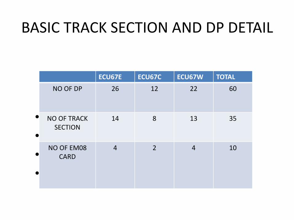
BASIC TRACK SECTION AND DP DETAIL
• Sailent Features
• .Total No of DP:- 60No
• .Total No Of Track Section:- 35
• .
ECU67E ECU67C ECU67W TOTAL
NO OF DP 26 12 22 60
NO OF TRACK SECTION
14 8 13 35
NO OF EM08 CARD
4 2 4 10
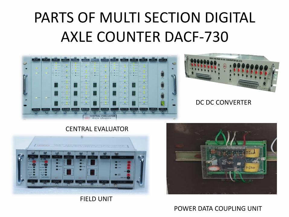
PARTS OF MULTI SECTION DIGITAL AXLE COUNTER DACF-730
FIELD UNIT
POWER DATA COUPLING UNIT
DC DC CONVERTER
CENTRAL EVALUATOR

PARTS OF MULTI SECTION DIGITAL AXLE COUNTER DACF-730
RESET PANEL
TRACK DEVICE
FIELD UNIT MASHROOM
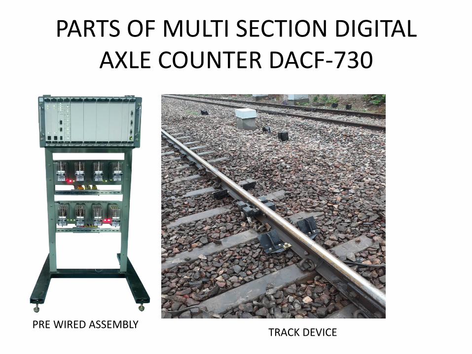
PARTS OF MULTI SECTION DIGITAL AXLE COUNTER DACF-730
PRE WIRED ASSEMBLYTRACK DEVICE
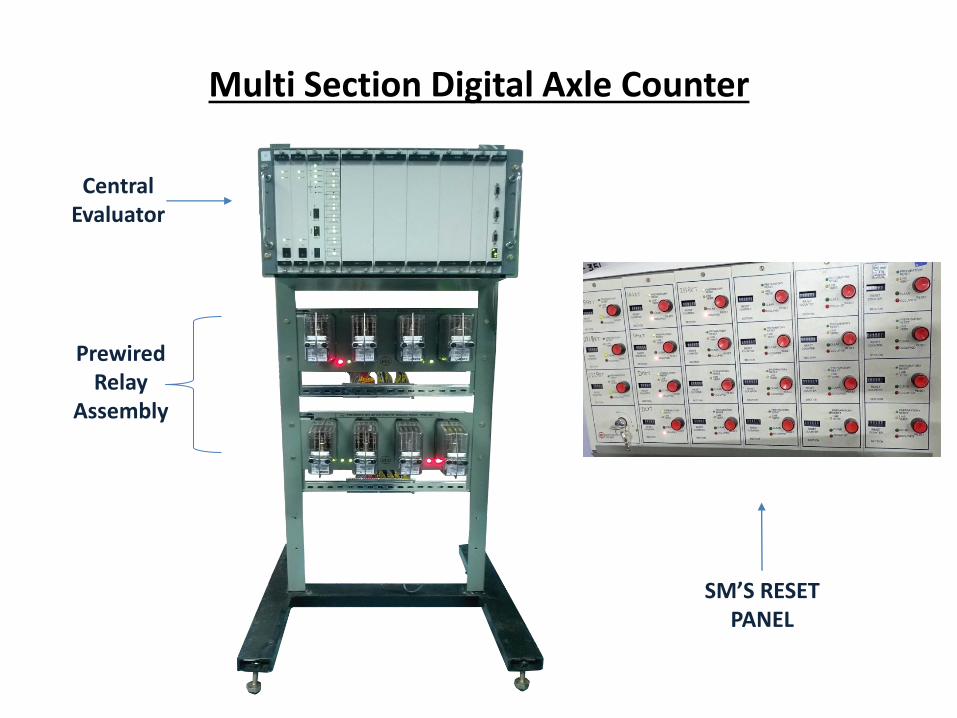
Multi Section Digital Axle Counter
Central Evaluator
Prewired Relay
Assembly
SM’S RESET PANEL
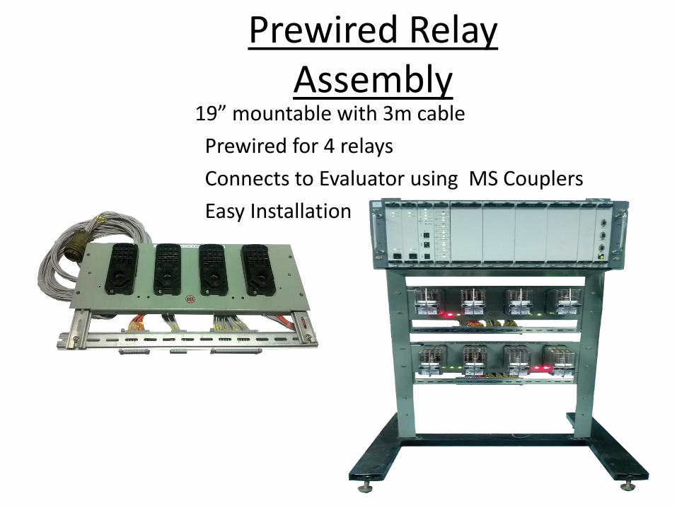
Prewired Relay Assembly
19” mountable with 3m cable
Prewired for 4 relays
Connects to Evaluator using MS Couplers
Easy Installation
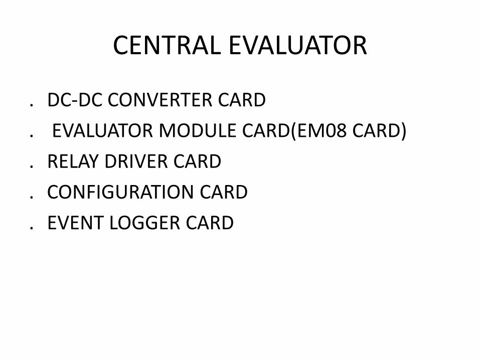
CENTRAL EVALUATOR
. DC-DC CONVERTER CARD
. EVALUATOR MODULE CARD(EM08 CARD)
. RELAY DRIVER CARD
. CONFIGURATION CARD
. EVENT LOGGER CARD
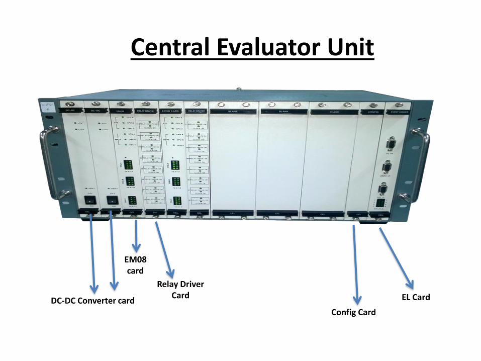
Central Evaluator Unit
DC-DC Converter card
EM08 card
Config Card
Relay Driver Card EL Card
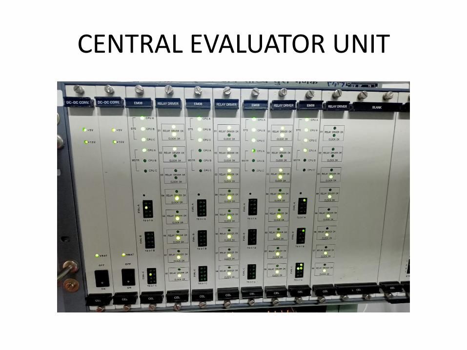
CENTRAL EVALUATOR UNIT

MSDAC - CENTRAL EVALUATOR UNIT
• C E N T R A L E V A L U A T O R C A R D F I L E H A V I N G T O T A L 1 4 N O O F S L O T S .
• 1 & 2 S L O T S F O R D C - D C C O N V E R T E R , 1 3 T H F O R C O N F I G U R A T I O N C A R D A N D 1 4 T H F O R E V E N T L O G E R C A R D , R E S T 3 r d T O 1 2 t h C A R D R E S E R V E F O R E M 0 8 C A R D A L O N G W I T H R E L A Y D R I V E C A R D .
• E v a l u a t o r M o d u l e C a r d
– 2 o u t o f 3 h a r d w a r e a r c h i t e c t u r e
– C a t e r s t o 8 D P
• R e l a y D r i v e r c a r d
– 8 v i t a l r e l a y o u t p u t s
• C o n f i g u r a t i o n C a r d
– E a s y c o n f i g u r a t i o n u s i n g G U I t o o l
• E v e n t L o g g e r C a r d
• R e d u n d a n t D C t o D C c o n v e r t e r
• 1 9 ” p r e w i r e d r a c k f o r d i f f e r e n t c o n f i g u r a t i o n s a v a i l a b l e
– 8 D P m o d e l i n 2 0 U r a c k
– 1 6 / 2 4 D P m o d e l i n 3 0 U r a c k
– 3 2 / 4 0 D P m o d e l i n 4 0 U r a c k
– D u a l 8 D P / 1 6 D P i n 4 0 U r a c k
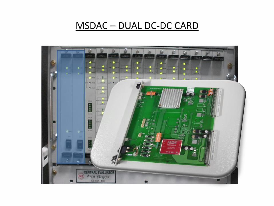
MSDAC – DUAL DC-DC CARD
MSDAC – DUAL DC-DC CARD
• THIS CARD OPERATES WITH 24V DC AND PROVIDES REQURED POWER SUPPLY TO CENTRAL EVALUATOR CARDS

MSDAC – 8 CH. EVALUATOR MODULE

MSDAC EVALUATOR MODULE(EM08)
• UP TO 5 EM08 CARD CAN BE INSTALLED IN CEU ALLOWING UP TO A MAXIUM OF 40 DP AND CAPABLE OF GIVING 40 TRACK RELAY OUTPUT.
• THIS MODULE GENERATES THE FINAL RELAY OUTPUT CONTROL SIGNAL FOR RELAY OUTPUT FOR RESPECTIVE TRACK SECTION.
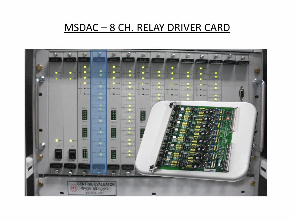
MSDAC – 8 CH. RELAY DRIVER CARD

RELAY DRIVER CARD
• RELAY DRIVE CARD GENERATES THE REQUIRED DRIVING VOLTAGE TO DRIVE Q TYPE 1000 OHM RELAYS
• THE PICKUP AND DROP CONTACT OF RELAYS ARE READ BACK FOR FAIL SAFE OUTPUT.

MSDAC – CONFIGURATION CARD

MSDAC – CONFIGURATION CARD
• THE CONFIGURATION CARD IN CENTRAL EVALUATOR STORES THE DIFFERENT CONFIGURATION USING CONFIGURATION STATION.
• IT CONFIGURE 40 DP AS PER RAILWAY REQUREMENT TO FORM TRACK SECTIONS.

MSDAC – EVENT LOGGER CARD
MSDAC – EVENT LOGGER CARD
• THE EVENT LOGGER CARD RECORDS VARIOUS EVENTS OCCURING IN THE MSDAC SYSTEM.
• IT CAN BE INTERFACE TO COMMERCIAL PC USING ONE OF THE 3 SERIAL PORTS AVAILABLE IN THE FACIAL PLATE OF THE CARD.
• 1st PORT IS USED FOR EVENT LOG .
• 2nd FOR EI INTERFACE SYSTEM.
• 3rd FOR FOR DATA LOGGER.
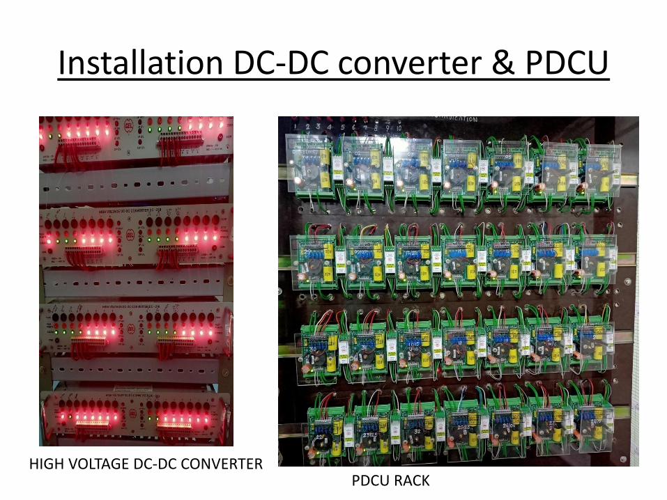
Installation DC-DC converter & PDCU
HIGH VOLTAGE DC-DC CONVERTERPDCU RACK

HIGH VOLTAGE DC - DC CONVERTER
• Input Voltage – 24V DC
• Output – 96V DC
• No. of Output Channels – 8 or 16 no’s
Central Electronics ltd.

POWER DATA COUPLING UNIT(PDCU)
POWER DATA COUPLING UNIT(PDCU)
• PDCU IS THE INTERFACE BETWEEN OUTDOOR EQUIPMENTS(DP) AND INDOOR EQUIPMENTS (EM-08).
• IT HAS A SUPERIMPOSING CKT FOR USING SAME CONDUCTOR FOR POWER AND DATA.
• 2 PDCU USED FOR ONE DETECTION POINT

MSDAC – RESET PANEL
• D o m i n o B a s e d D e s i g n
• S e c t i o n - w i s e R e s e t t i n g
• S e c t i o n C l e a r, O c c u p i e d , P r e p a r a t o r y R e s e t
& L i n e V e r i f i c a t i o n i n d i c a t i o n
• R e s e t B u t t o n
• S M ’s C o n t r o l K e y
• S e c t i o n w i s e c o u n t e r f o r r e c o r d i n g r e s e t
• F O R R E S E T I N G - 1 s t P R E S S S M K E Y T H E N
C O N C E R N T R A C K S E C T I O N P U S H B U T T O N
A N D R E L E A S E F I R S T P U S H B U T T O N T H E N S M
K E Y.

PARTS OF MULTI SECTION DIGITAL AXLE COUNTER DACF-730
MONITORING UNIT

MONITORING UNIT
Monitoring Unit
MONITORING UNIT
• MONITERING UNIT IS USED TO DISPLAY THE STATUS OF ALL FIELD UNIT DP, AND TRACK SECTION STATUS.
• IT IS INTERFACED WITH CENTRAL EVALUATOR RS422 PROTOCOL.
• M/U RECEIVE THE DETAILS FROM EM08 AND PROCESSED TO DISPLAY THE SAME ON LCD PANEL.
• IT DISPLAY THE COMPLETE INFORMATION OF THE FIELD UNIT i.e. COUNTS,ADRESS OF THE DP,CONTRIBUTION OF THE DP IN REQUIRED TRACK SECTION,HEALTH AND ERROR CODE WITH ITS DISCRIPTION.

MONITORING UNIT
• IT DISPLAY THE TRACK SECTION INFORMATION, TRACK STATUS CONDITION WEATHER THE SECTION IS HEALTHY, UNHEALTHY, OCCUPIED OR CLEAR, ITS ERROR CODE IN CASE TRACK SECTION IS UNHEALTHY
• THE MONITORING UNIT OPERATES ON 24V DC.
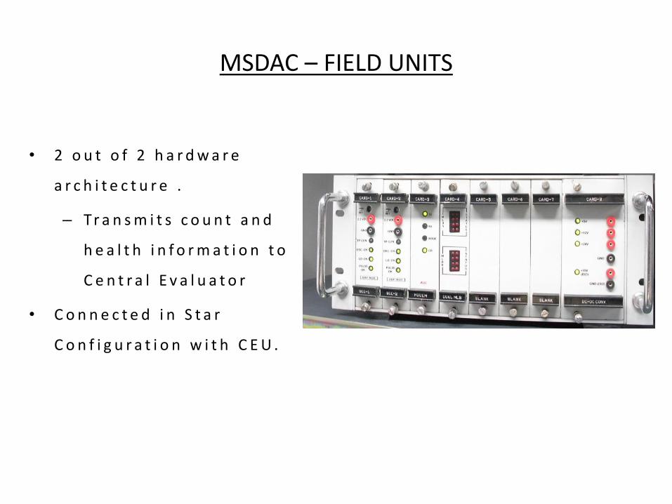
MSDAC – FIELD UNITS
• 2 o u t o f 2 h a r d w a r e
a r c h i t e c t u r e .
– Tr a n s m i t s c o u n t a n d
h e a l t h i n f o r m a t i o n t o
C e n t r a l E v a l u a t o r
• C o n n e c t e d i n S t a r
C o n f i g u r a t i o n w i t h C E U .

FIELD UNIT CONSIST OF
• SCC CARD 1
• SCC CARD 2
• MODEM CARD
• DUAL MLB CARD
• DC-DC CONVERTER CARD
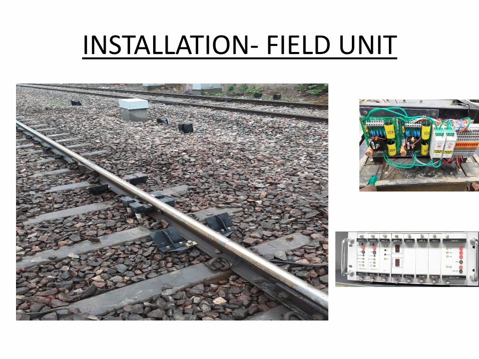
INSTALLATION- FIELD UNIT
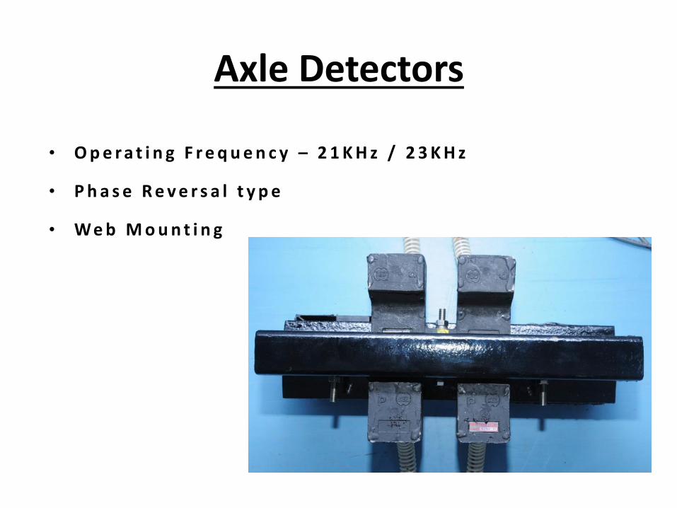
Axle Detectors
• O p e r a t i n g F r e q u e n c y – 2 1 K H z / 2 3 K H z
• P h a s e R e v e r s a l t y p e
• We b M o u n t i n g

TROUBLE SHOOTING OF MSDAC
FAMILIARITY WITH ERROR CODES
10 20
40 80
1 2
4 8
5 6
7 8
1 2
3 4
FRONT VIEW VALUE GIVEN TO LED’s
LSB
MSB
LSB
MSB

TROUBLE SHOOTING OF MSDAC
1+4+10+20=35
1
4
10 20

HOW TO CALCULATE THE ERROR CODE OF FIELD UNIT.
• THE EXAMPLE FOR READING AN ERROR FROM THE BELOW LED'S IS AS FOLLOW:-LED'S 1&3 LSB AND LED's 5&6 of MSB GLOW WITH FLASHING AND ALL OTHER LED's ARE OFF. BY ADDING LSB+MSB LED's THE ERROR NO. IS 35 i.e. NEGATIVE COUNT ERROR.
1+4+10+20=35

TROUBLE SHOOTING OF MSDAC
• OBSERVATION:- Error No. 14 is displayed with flashing LED’s if any card is removed or not inserted properly
• ACTION TAKEN:- Insert all the cards properly or replace all the MLB cards.
TROUBLE SHOOTING OF MSDAC
• OBSERVATION:- Error No. 24 is displayed when any of the card is not present in the system.
• ACTION TAKEN:- Check all the cards are properly installed in the unit. If problem persists replace the MLB card.

TROUBLE SHOOTING OF MSDAC
• OBSERVATION:- Error No. 30 (LINK Error) is displayed when link is open.
• ACTION TAKEN:- Check the communication link between the units and rectify the fault.

TROUBLE SHOOTING OF MSDAC
• OBSERVATION:- Error No. 31 (Sequence Error) is displayed when sequence of pulses is not correct.
• ACTION TAKEN:- Check the arrangement of detectors. It shall be at proper height from top of rail. Check cards SCC1&2 and replace if necessary.
TROUBLE SHOOTING OF MSDAC
• OBSERVATION:- Error No. 32 (Self Count Mismatch) is displayed if there is difference between the counts of two MLB cards in the local unit.
• ACTION TAKEN:- Reset the system. If error persists replace the MLB cards with the spare cards. Send the cards for repair.
TROUBLE SHOOTING OF MSDAC
• OBSERVATION:- Error No. 33 (In Out Error) is displayed if the number of axles going out of section is more than coming into section.
• ACTION TAKEN:- Check the system for error and apply reset to normalize the system.

TROUBLE SHOOTING OF MSDAC
• OBSERVATION:- Error No. 34 (out before in error) is displayed when system is in preparatory state and train exits from the section without entering into the section.
• ACTION TAKEN:- Check the axle detectors. Check SCC1 card & replace it if found faulty.
TROUBLE SHOOTING OF MSDAC
• OBSERVATION:- Error No. 35 (Negative count error) is displayed with flashing LED’s when count out of the section are more than the counts into the section. Check signals dip at both locations in single line section.
• ACTION TAKEN:- Check signals dip and coil position at entry end Track device. Check DC voltage in SCC 1 & 2 cards.

TROUBLE SHOOTING OF MSDAC
• OBSERVATION:- Error No. 36 (Shunt error) is displayed for improper shunting on axle detectors.
• ACTION TAKEN:- Station Master has to apply reset after section is verified as per SWR. Movement of pilot train in the section makes system clear.
TROUBLE SHOOTING OF MSDAC
• OBSERVATION:- Error No. 37 (Supervisory Error) is displayed when any one of the axle detector signals become low.
• ACTION TAKEN:- Check the Tx and Rx signal level of the axle detectors. It should be as per the recorded readings. Check SCC 1&2 cards DC voltage. Adjust or replace if any of the above is not OK.

TROUBLE SHOOTING OF MSDAC
• OBSERVATION:- Error No. 40 (Communication Error) is displayed when communication between two units is improper.
• ACTION TAKEN:- Check the pair used for communication. Check that no parallel wires are used for modem communication. Check that correct quad pair is used for communication. If problem persists replace the spare pair.

ERROR CODE OF FIELD UNIT IN
DO’S & DON’T
DO’S • The inter connection drawings are to be followed for connecting the Transmitter &
Receiver coils. Tx1 is 21 KHz, Tx2 is 23 KHz & Rx1 and Rx2 coils are 21 KHz & 23 KHz, respectively.
• Ensure that Receiver and Transmitter coil cables have been laid in different pipes.• Ensure that both the TX coils & Rx coils are having proper alignment on Rail.• Ensure that packing of sleepers with ballast on both sides of Axle detector is proper.• Check that metal sheaths of the outdoor cable are connected to earth at both ends.• The recommended cables for wiring of the system at site should be used.• Proper Twisting of Quad pair to be done.• The steady Battery voltage 24V should be maintained.• The cable connections should not be connected loosely.• The M.S Circular connectors of MSDAC are checked and maintained firmly.• The MSDAC & Reset box is provided with sealing arrangement. They should be sealed at
site.• Resetting should be done only after ensuring that there is no train in the section
DON’T
• Don’t install the Axle detectors near the rail joint (should be more than 6 sleepers away).
• Don’t install the Axle detectors where the rail is badly worn out.
• Don’t cut or join the Transmitter / Receiver cables supplied along with the coil. It would result in change of frequency of signal.
• Don’t lay the TX and RX coil cables in the same pipe.
• Don’t use any other outdoor cable other than the recommended cables.
• Avoid installing the Axle detectors on curve of rail / too much slope of rail to the possible extent.
• Don’t remove the cards from MSDAC FIELD units under power ON condition of system.
• Remove card if necessary after Switching OFF the power to the unit.