handbook on maintenance of digital axle counter
TRANSCRIPT

Hkkjr ljdkj &GOVERNMENT OF INDIA jsy ea=ky;& MINISTRY OF RAILWAYS ¼dk;kZy;hu iz;ksx gsrq½& (For official use only)
Handbook on
MAINTENANCE of
MAHARAJPUR, GWALIOR – 474 005
CAMTECH/S/PROJ/2012-13/HB-DAC (M)/1.0
February 2013

FOREWORD
Track circuits and Axle counters play a vital role in railway signalling as these detect the presence of train vehicle on a given section of track. Digital Axle Counters; the advanced version of conventional axle counters are progressively being installed on Indian Railways due to their enhanced safety features and reliability. CAMTECH is continuously making efforts in documentation and upgradation of information on advanced maintenance practices. The current handbook consisting of maintenance information on Digital Axle Counters of RDSO approved firms is a further step in this direction. The information given in this handbook will help signal personnel in maintaining the above system. CAMTECH Gwalior A.R.Tupe Date: 11.03.2013 Executive Director

PREFACE
Conventional track circuits and axle counters have their own limitations in terms of its range of operation and reliability and require frequent maintenance. The Micro-controller and software based Digital Axle Counters require less maintenance and have added feature of diagnostics information through LEDs. Digital Axle Counters, both Single section and Multi Section have applications in straight sections and point zones of Station area as well as in proving of Block section. This handbook has been prepared to help the field personnel in maintaining Digital Axle Counters installed in their section for trouble-free performance. The handbook has been divided into vendor specific sections; containing maintenance information on the systems manufactured by different RDSO approved firms. It is clarified that this handbook does not supersede any existing provisions laid down in Signal Engineering Manual, Railway Board publications and RDSO publications. This handbook is not statutory and instructions given in it are for the purpose of guidance only. We are sincerely thankful to Shri R. Meena, Sr.D.S.T.E./Agra/NC Rly., M/s Eldyne Electrosystems Pvt. Ltd., Kolkata, M/s Central Electronics Ltd., Sahibabad, M/s G.G.Tronics, Bangalore, M/s Siemens Ltd. Mumbai and field personnel who helped us in preparation of the handbook. Since technological upgradation and learning is a continuous process, you may feel the need for some addition/modification in this handbook. If so, please give your comments on email address [email protected] or write to us at Indian Railways Centre for Advanced Maintenance Technology, In front of Adityaz Hotel, Maharajpur, Gwalior (M.P.) 474005. CAMTECH Gwalior D.K.M.Yadav Date: 08.03.2013 Jt .Director (S&T)

Contents Description Pages
Foreword
i
Preface
iii
Contents
v
Correction Slip
ix
Disclaimer & Our objective
x
Section I : Maintenance of Az LS Eldyne Single Section Digital Axle Counter
1-16
Section II: Maintenance of Az LM Eldyne Multi Section Digital Axle Counter
1-9
Section III: Maintenance of Az S 350 U Siemens Multi Section Digital Axle Counter
1-11
Section IV: Maintenance of DACF 710 A & DACF 710 P CEL Single Section Digital Axle Counter
1-9
Section V: Maintenance of G36 GG Tronics Single Section Digital Axle Counter
1-12
Annexure I – Abbreviations
Annexure II – References

ISSUE OF CORRECTION SLIPS The correction slips to be issued in future for this handbook will be numbered as follows:
CAMTECH/S/PROJ/2012-13/HB-DAC (M)/1.0# XX date .......
Where “XX” is the serial number of the concerned correction slip (starting from 01 onwards).
CORRECTION SLIPS ISSUED
Sr. No. of Correction
Slip
Date of issue
Page no. and Item No. modified
Remarks

DISCLAIMER
It is clarified that the information given in this handbook does not supersede any existing provisions laid down in the Signal Engineering Manual, Railway Board and RDSO publications. This document is not statuary and instructions given are for the purpose of guidance only. If at any point contradiction is observed, then SEM, Railway Board/RDSO guidelines may be referred or prevalent Zonal Railways instructions may be followed.
----------------------------------------------------------------------------------------------------
OUR OBJECTIVE
To upgrade Maintenance Technologies and Methodologies and achieve improvement in Productivity and Performance of all Railway assets and manpower which inter-alia would cover Reliability, Availability and Utilisation.
If you have any suggestion & any specific comments, please write to us:
Contact person: Director (Signal & Telecommunication) Postal Address: Centre for Advanced Maintenance Technology, Maharajpur,
Gwalior (M.P.) Pin Code – 474 005
Phone : 0751 - 2470185
Fax : 0751 – 2470841 Email : [email protected]

Section I
Maintenance of
Eldyne AzLS Single Section Digital Axle Counter
CAMTECH/S/PROJ/2012-13/HB- DAC (M) February 2013
Contents
Section I: Maintenance of Az LS Eldyne Single Section Digital Axle Counter
Sr. No. Description Page No.
1.1 Introduction 1
1.2 Fixing of track devices after replacement of rail 1
1.3 Termination details of EAK 3
1.4 Adjustment of Rail contact Tx head with Dummy wheel and Tool Kit
5
1.5 Test equipment (Tool Kit) ETU001 6
1.6 Functions of Selector Switch in ETU 001 6
1.7 Parameters to be checked for adjustment of rail contact 7
1.8 Adjustment procedure 10
1.9 Reset Box 11
1.10 Steps to initiate a reset 11
1.11 Types of resetting for AzLS 12
1.12 Check points for maintenance 12
1.13 Do’s & Don’ts 13
1.14 Log Sheet 16

CAMTECH/S/PROJ/12-13/HB-DAC (M)
Section I – Maintenance of AzLS Eldyne SSDAC February 2013
1
Section I Maintenance of
Az LS Eldyne Single Section Digital Axle Counter
1.1 Introduction The AzLS system consists of at least two detection points Zp30CA-2, one at each end (entry
& exit) of the track section to be monitored. It consists of following parts: (a) Outdoor Trackside system consisting of
(i) Rail contacts (SK30H) - It consists of two coil sets Sk1 and Sk2, both installed on the same rail. The transmitter heads (Tx) are installed on the outside of the rail and receiver heads (Rx) are installed on the inside of the rail directly opposite the respective Tx heads. The two Tx coils are fed with different frequencies (approx. 30.6 kHz and 28 kHz). The SK30H is fitted by three bolts to the web of the rail. The vertical position of the respective mounting holes depends on the rail profile.
(ii) Track-Side Electronic Unit (EAK).
SK30H and EAK together form one detection point Zp30CA-2. Each Tx/Rx head is equipped with fixed cables for connection to the electronic junction box (EAK30H). (available in lengths 4m, 5.5m and 8m)
(b) Communication Link (A pair of star quad cable) (c) Reset Relay (1000 ohm AC immunized Q series) (d) Vital Relay (1000 Ohm AC immunized Q series 24 V 8F/8B) 1.2 Fixing of track devices after replacement of rail Drill the mounting holes on the rail web in correct position as per following approximation formula: a = (0.409 * h), where a = height of the mounting hole, h = height of the rail
Fig. 1.1: Position of mounting holes for installation of Rail Contacts
a1 or a2 or a3 = a calculated +1.5 mm b =13 mm + 0.2 mm c =148 mm + 0.2 mm

CAMTECH/S/PROJ/12-13/HB-DAC (M)
Section I – Maintenance of AzLS Eldyne SSDAC February 2013
2
Height of mounting hole for different rail profiles is given below:
Rail Profile 90 lbs 52 Kg 60 Kga [mm] 56 mm 63 mm 68 mm
The final three holes of diameter 13mm are drilled on the rail web with the help of drilling jig. consisting of: (i) Drilling template (ii) Mounting device for the drilling machine (iii)Templates for the standard rail profiles (iv) Fastening device (v) The drilling machine
Fig.1.2: Mounting of Rail Contacts (Tx heads on the outside and Rx heads on the inside of the rail)
Fig.1.3: EAK backplane assembly (without boards) as viewed from top
1
6a
45
3b¹3a¹ 2¹
6b
1 Terminal for line-cable
2¹ Slot for Digital Evaluator / ISDN Board
3 (a/b) Address switches
5 Test equipment interface
4 Slot for analog board
6(a/b) WAGO-terminal
2² Slot for Digital Board
2²
3b²3a²
Washer
Nut
Nylon Bush
Insulating Plate
M12 bolt
M8 bolt
CAMTECH/S/PROJ/12-13/HB-DAC (M)
Section I – Maintenance of AzLS Eldyne SSDAC February 2013
3
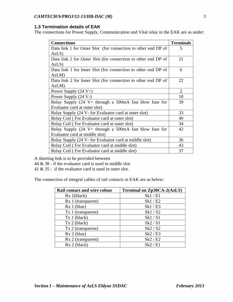
1.3 Termination details of EAK The connections for Power Supply, Communication and Vital relay in the EAK are as under:
A shorting link is to be provided between 44 & 38 - if the evaluator card is used in middle slot. 41 & 35 - if the evaluator card is used in outer slot. The connection of integral cables of rail contacts in EAK are as below:
Rail contact and wire colour Terminal on Zp30CA-2(AzLS) Rx 1(black) Sk1 / E1 Rx 1 (transparent) Sk1 / E2 Rx 1 (blue) Sk1 / E3 Tx 1 (transparent) Sk1 / S2 Tx 1 (black) Sk1 / S1 Tx 2 (black) Sk2 / S1 Tx 2 (transparent) Sk2 / S2 Rx 2 (blue) Sk2 / E3 Rx 2 (transparent) Sk2 / E2 Rx 2 (black) Sk2 / E1
Connections TerminalsData link 1 for Outer Slot (for connection to other end DP of AzLS)
5
Data link 2 for Outer Slot (for connection to other end DP of AzLS)
21
Data link 1 for Inner Slot (for connection to other end DP of AzLM)
6
Data link 2 for Inner Slot (for connection to other end DP of AzLM)
22
Power Supply (24 V+) 2 Power Supply (24 V-) 18 Relay Supply (24 V+ through a 500mA fast blow fuse for Evaluator card at outer slot)
39
Relay Supply (24 V- for Evaluator card at outer slot) 33 Relay Coil ( For Evaluator card at outer slot) 40 Relay Coil ( For Evaluator card at outer slot) 34 Relay Supply (24 V+ through a 500mA fast blow fuse for Evaluator card at middle slot)
42
Relay Supply (24 V- for Evaluator card at middle slot) 36 Relay Coil ( For Evaluator card at middle slot) 43 Relay Coil ( For Evaluator card at middle slot) 37
CAMTECH/S/PROJ/12-13/HB-DAC (M)
Section I – Maintenance of AzLS Eldyne SSDAC February 2013
4
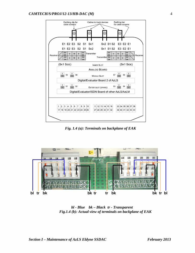
Fig. 1.4 (a): Terminals on backplane of EAK
bl - Blue bk – Black tr - Transparent Fig.1.4 (b): Actual view of terminals on backplane of EAK
bl tr bk bk tr bl bk tr tr bk
x
x x
x
CAMTECH/S/PROJ/12-13/HB-DAC (M)
Section I – Maintenance of AzLS Eldyne SSDAC February 2013
5
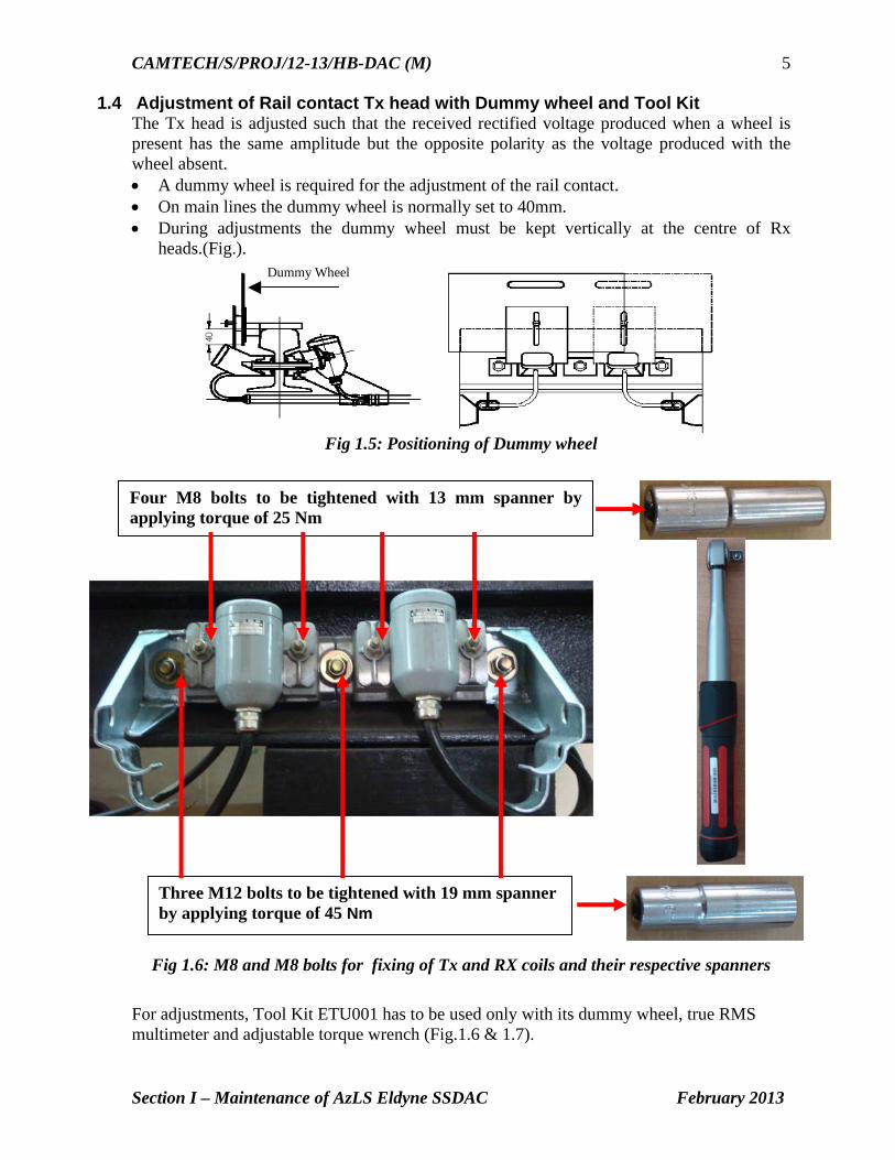
1.4 Adjustment of Rail contact Tx head with Dummy wheel and Tool Kit The Tx head is adjusted such that the received rectified voltage produced when a wheel is present has the same amplitude but the opposite polarity as the voltage produced with the wheel absent. A dummy wheel is required for the adjustment of the rail contact. On main lines the dummy wheel is normally set to 40mm. During adjustments the dummy wheel must be kept vertically at the centre of Rx
heads.(Fig.). Dummy Wheel
Fig 1.5: Positioning of Dummy wheel
Fig 1.6: M8 and M8 bolts for fixing of Tx and RX coils and their respective spanners
For adjustments, Tool Kit ETU001 has to be used only with its dummy wheel, true RMS multimeter and adjustable torque wrench (Fig.1.6 & 1.7).
Four M8 bolts to be tightened with 13 mm spanner by applying torque of 25 Nm
Three M12 bolts to be tightened with 19 mm spanner by applying torque of 45 Nm

CAMTECH/S/PROJ/12-13/HB-DAC (M)
Section I – Maintenance of AzLS Eldyne SSDAC February 2013
6
1.5 Test equipment (Tool Kit) ETU001 Test equipment ETU001 is utilized for 1) Signal voltage level and frequency measurement. 2) AC & DC Current /Voltage measurement. During Installation, Testing, Commissioning,
Diagnosing and Calibrating the Outdoor Unit of AzLS & AzLM Axle Counters.
Fig.1.7: Test equipment (Tool Kit) ETU001
Contents of Test Equipment
1) True RMS digital multimeter with probe set (Type Fluke-177)– 1 no. 2) Extended wired Socket to interface with diagnostic plug – 1 no. 3) Selector Switch on panel-base – 1 no. 4) Adjustable reversible torque wrench (Type Norbar –6013011)- 1 no. 5) Deep Socket inserts with (13 mm & 19 mm) – I set. 6) 19 mm combined double ended spanner – 1 no. 7) Dummy wheel – 1 no. 8) Screw driver individual (Type Wago-210119) – 1 no. 9) Screw driver set (Type Taparia 812) – 1 set. 10) Screw driver individual (Taparia-932) – 1 no.
1.6 Functions of Selector Switch in ETU 001
Selector switch position 1: Shows the value of the output of 1st internal DC-DC Converter (Channel1) in Analog card.
The selector switch position 2: Shows the value of output voltage of 2nd internal DC-DC Converter (Channel2) in Analog card.
Selector switch position 3: OFF Selector switch position 4: Shows the rectified Rx voltage (MESSAB1) for SK1. For fine
adjustment the potentiometer R2 on the Analog board of EAK should be used.

CAMTECH/S/PROJ/12-13/HB-DAC (M)
Section I – Maintenance of AzLS Eldyne SSDAC February 2013
7
Selector switch position 5: Shows the value of reference voltage for SK1 (PEGUE1).
This can be adjusted by the potentiometer R1 on the Analog board. Selector switch position 6: OFF Selector switch position 7: Shows the rectified Rx voltage (MESSAB2) for SK2. For fine
adjustment the potentiometer R4 on the Analog board should be used. Selector switch position 8: Shows the reference voltage for SK2 (PEGUE2). This can be
adjusted by the potentiometer R3 on the Analog board. Selector switch position 9: OFF
R4 R3 R1 R2
Fig. 1.8 : Potentiometers in Analog board for adjustment
PCB Potentiometer Function Analogue R1 Potentiometer for sk1 reference voltage PEGUE1
R2 Potentiometer for sk1 voltage MESSAB1 R3 Potentiometer for sk2 reference voltage PEGUE1 R4 Potentiometer for sk2 voltage MESSAB2
Note: Rotate R2 (or R4) clockwise to increase the Rectified Voltage MESSAB1 or MESSAB2. Rotate R2 (or R4) anti-clockwise to decrease the Rectified Voltage MESSAB1 or
MESSAB2. Rotate R1 (or R3) clockwise to increase the Reference Voltage PEGUE1 or PEGUE2. Rotate R1 (or R3) anti-clockwise to decrease the Reference Voltage PEGUE1 or
PEGUE2.
Switches
Switch Function S1 Switch fixed by factory in position 1.May be put into position 2 for using
rail contact with longer cable length. S2 S3 Switch fixed by factory in position 1.May be put into position 2 to raise
the transmitter power of the rail contact for better signal to noise ratio.
1.7 Parameters to be checked for adjustment of rail contact a) Output of 1st internal DC-DC Converter (Channel 1): Specified range 22VDC to 35VDC. b) Output of 2nd internal DC-DC Converter (Channel 2): Specified range 22VDC to
35VDC.
CAMTECH/S/PROJ/12-13/HB-DAC (M)
Section I – Maintenance of AzLS Eldyne SSDAC February 2013
8
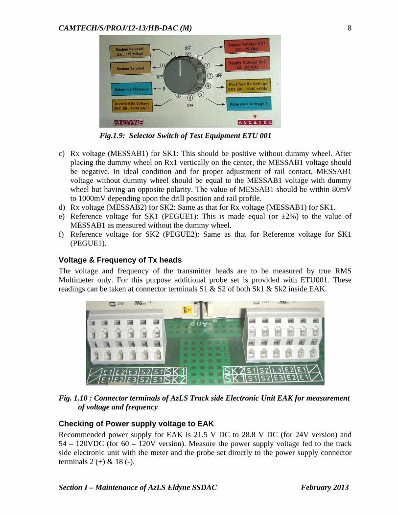
Fig.1.9: Selector Switch of Test Equipment ETU 001 c) Rx voltage (MESSAB1) for SK1: This should be positive without dummy wheel. After
placing the dummy wheel on Rx1 vertically on the center, the MESSAB1 voltage should be negative. In ideal condition and for proper adjustment of rail contact, MESSAB1 voltage without dummy wheel should be equal to the MESSAB1 voltage with dummy wheel but having an opposite polarity. The value of MESSAB1 should be within 80mV to 1000mV depending upon the drill position and rail profile.
d) Rx voltage (MESSAB2) for SK2: Same as that for Rx voltage (MESSAB1) for SK1. e) Reference voltage for SK1 (PEGUE1): This is made equal (or ±2%) to the value of
MESSAB1 as measured without the dummy wheel. f) Reference voltage for SK2 (PEGUE2): Same as that for Reference voltage for SK1
(PEGUE1).
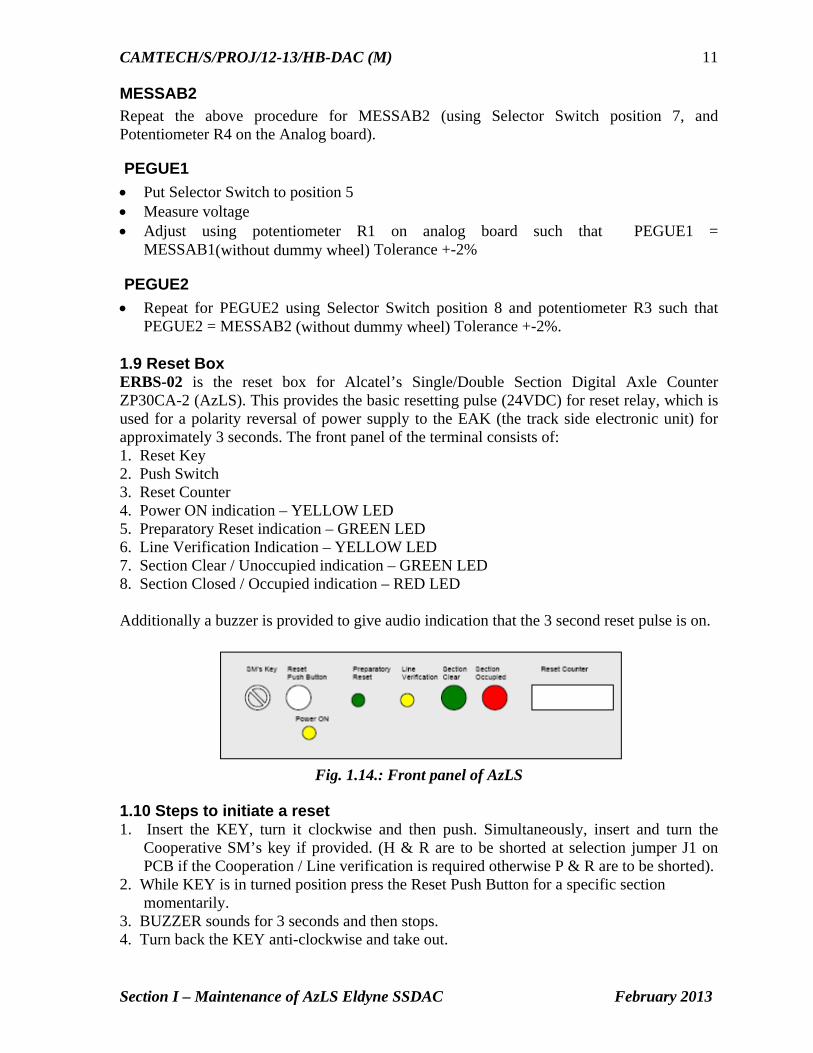
Voltage & Frequency of Tx heads The voltage and frequency of the transmitter heads are to be measured by true RMS Multimeter only. For this purpose additional probe set is provided with ETU001. These readings can be taken at connector terminals S1 & S2 of both Sk1 & Sk2 inside EAK.
Fig. 1.10 : Connector terminals of AzLS Track side Electronic Unit EAK for measurement of voltage and frequency
Checking of Power supply voltage to EAK Recommended power supply for EAK is 21.5 V DC to 28.8 V DC (for 24V version) and 54 – 120VDC (for 60 – 120V version). Measure the power supply voltage fed to the track side electronic unit with the meter and the probe set directly to the power supply connector terminals 2 (+) & 18 (-).
8
10
11

CAMTECH/S/PROJ/12-13/HB-DAC (M)
Section I – Maintenance of AzLS Eldyne SSDAC February 2013
9
Communication (data) between two EAK Communication pair is connected to Connector 5 and 21, if Digital Card is installed in outer slot Connector 6 and 22, if Digital Card is installed in middle slot
Fig. 1.11 : Connector terminals of AzLS Track side Electronic Unit EAK for power supply and communication (data) link
Vital Relay output If Digital Card is installed in outer slot Check at Connector 33 and 39, for on-board vital relay input Check at Connector 34 and 40, for on-board vital relay output
If Digital Card is installed in middle slot
Check at Connector 36 and 42, for on-board vital relay input Check at Connector 37 and 43, for on-board vital relay output Voltage at relay should be more than 20 V.
MOVs – AzLS
Fig. 1.12 : Connection details of MOVs in EAK
For Digital Card installed in middle slot
For Digital Card installed in outer slot
For Analog Card
For Digital Card of AzLM
installed in outer slot

CAMTECH/S/PROJ/12-13/HB-DAC (M)
Section I – Maintenance of AzLS Eldyne SSDAC February 2013
10
1.8 Adjustment procedure Connect the test equipment to the diagnostic port of EAK as shown in fig.1.13 Steps to adjust the rectified voltage
MESSAB1 Put Selector Switch to position 4. Measure the rectified voltage with and without dummy wheel. Turn Potentiometer R2 on the Analog board to positive max. The rectified voltage without dummy wheel must be set to positive maximum. If there is a big difference between the positive value and the negative value, move the
Tx heads upward or downward along the serration and adjust to optimum position. Taking the transmitter head upwards increases the negative voltage and decreases the positive voltage and vice versa.
Adjust using Pot. R2 such that rectified voltage with and without dummy wheel are absolute equal (equal but having opposite polarity). Tolerance <=30mV.
After getting the positive and negative voltages within the above specified tolerance limit tighten the transmitter head properly with the torque wrench set at 25 Nm.
Trolley suppression For Trolley suppression to be effective, the positive voltage (without dummy wheel) should be greater than the negative voltage (with dummy wheel) by a value not less than 30 mV so that the rectified Rx voltage does not go to negative with the specified trolley wheel. It is recommended that the adjustment should be done using a spoke trolley wheel that is normally used in the section.
Fig.1.13: Connection of tool kit to diagnostic port of EAK for measurement of parameters
CAMTECH/S/PROJ/12-13/HB-DAC (M)
Section I – Maintenance of AzLS Eldyne SSDAC February 2013
11
MESSAB2 Repeat the above procedure for MESSAB2 (using Selector Switch position 7, and Potentiometer R4 on the Analog board).
PEGUE1
Put Selector Switch to position 5 Measure voltage Adjust using potentiometer R1 on analog board such that PEGUE1 =
MESSAB1(without dummy wheel) Tolerance +-2%
PEGUE2 Repeat for PEGUE2 using Selector Switch position 8 and potentiometer R3 such that
PEGUE2 = MESSAB2 (without dummy wheel) Tolerance +-2%. 1.9 Reset Box ERBS-02 is the reset box for Alcatel’s Single/Double Section Digital Axle Counter ZP30CA-2 (AzLS). This provides the basic resetting pulse (24VDC) for reset relay, which is used for a polarity reversal of power supply to the EAK (the track side electronic unit) for approximately 3 seconds. The front panel of the terminal consists of: 1. Reset Key 2. Push Switch 3. Reset Counter 4. Power ON indication – YELLOW LED 5. Preparatory Reset indication – GREEN LED 6. Line Verification Indication – YELLOW LED 7. Section Clear / Unoccupied indication – GREEN LED 8. Section Closed / Occupied indication – RED LED Additionally a buzzer is provided to give audio indication that the 3 second reset pulse is on.
Fig. 1.14.: Front panel of AzLS
1.10 Steps to initiate a reset 1. Insert the KEY, turn it clockwise and then push. Simultaneously, insert and turn the
Cooperative SM’s key if provided. (H & R are to be shorted at selection jumper J1 on PCB if the Cooperation / Line verification is required otherwise P & R are to be shorted).
2. While KEY is in turned position press the Reset Push Button for a specific section momentarily.
3. BUZZER sounds for 3 seconds and then stops. 4. Turn back the KEY anti-clockwise and take out.

CAMTECH/S/PROJ/12-13/HB-DAC (M)
Section I – Maintenance of AzLS Eldyne SSDAC February 2013
12
Each reset is registered in the sealed reset COUNTER unit. The count increases by one after each reset commanded by the operator.
1.11 Types of resetting for AzLS AzLS V1.1 provides four types of reset: 1. Single point preparatory reset (for berthing section) This reset does not clear the section immediately. It is sufficient that one of the detection points of the relevant section receives a preparatory reset. After carrying out the preparatory reset, a train must pass through the section on “caution running conditions”. Only then the section will be cleared. 2. Two point co-operative preparatory reset (for block section) The reset command is to be applied to both detection points within one hour. If this time elapses, the reset command is rejected. The other conditions are same as given in clause 1 above. 3. Single point hard reset (for point zone) It is sufficient that one of the detection points of the relevant section receives a hard reset. In addition to this pressing and turning of verification switch is required. The hard reset clears the section immediately. 4. Two point Co-operative hard reset The two point hard reset is initiated through individual external relay circuits which reverse the polarities of the supply voltages to at least two detection points of the section.
1.12 Check points for maintenance Carry out visual inspection of trackside equipment i.e. EAK, rail contacts and integral
cables (connecting leads), earthing etc. Check physically whether the rail contacts and cabling including earthing connections
are proper. Ensure that Tx heads are clear of rail. Ensure the proper size and tightness of deflectors and that these are fitted at least 250
mm away from rail contacts (Tx/Rx coils). Ensure for proper fixing of Track side connection box (EAK) on the mushroom base
plate and all 4 nos. screws are tight. Ensure that cable armours are properly earthed in location box. Check for proper spacing (min. 350 mm) and packing of sleepers on which track
devices are fitted. Check that the earthing connection of mushroom cover/apparatus case is intact and in
good condition, the earth lead wire and nut connecting earth wire etc. are not corroded.
Check that cable pairs used are properly dressed and terminated in such a way that no conductors remain exposed and check that no individual conductor are made spiral. These should be twisted in pair to improve EMC.
CAMTECH/S/PROJ/12-13/HB-DAC (M)
Section I – Maintenance of AzLS Eldyne SSDAC February 2013
13
Check that mushroom cover is properly fixed and there should be no possibility for entry of rain water.
Check the input voltage at location box/EAK keeping the charger OFF for at least 15 min. Voltage at location box/EAK should not go below 21.5 V for 24 V EAK and 54 V for 60 V EAK.
Check ripple voltage of power supply at EAK, it should not exceed 10 mv peak to peak.
Check rectified voltage (with dummy wheel) and reference voltages are within limit. Check the cards are in proper position and both analog and digital cards are fitted
firmly in their corresponding slot. Measure the earth resistance and paint its value on earth enclosures/nearest wall. If
required take suitable steps to improve the earth resistance. It should be less than 1 Ohm.
1.13 Do’s & Don’ts
For reduction in temperature, paint the inside and outside of mushroom cover (apparatus case for EAK) with temperature retardant paint (white).
Note: The newly fabricated mushroom covers are supplied with a coating of paint on inside and outside faces by the manufacturer hence painting is not required.
Always use 13mm high speed drill bit to drill holes on rail web. Place foam packings between top of the Digital/Analog cards and dust cover to avoid
loosening due to vibrations. (As per practice in BPL division W.C.Rly.) Tighten M8 bolts (on transmitter heads) with torque of 25Nm and M12 bolts (to fix rail
contact on rail web) with torque of 45Nm. Torque greater than specified value will break the bolts and torque less than specified value will make the rail contact loosely fitted.
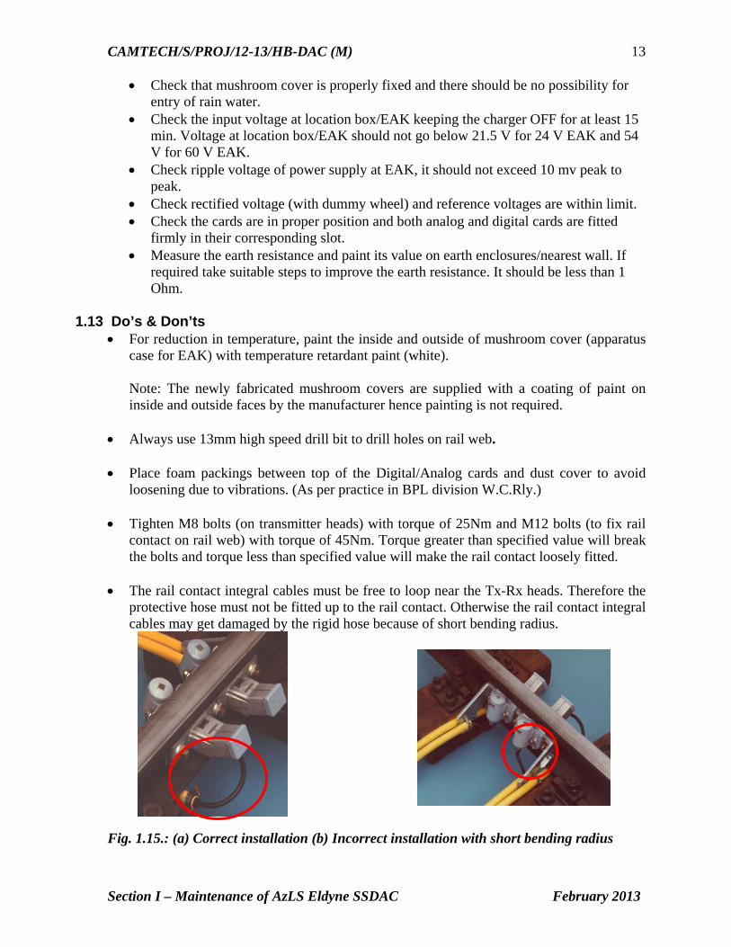
The rail contact integral cables must be free to loop near the Tx-Rx heads. Therefore the
protective hose must not be fitted up to the rail contact. Otherwise the rail contact integral cables may get damaged by the rigid hose because of short bending radius.
Fig. 1.15.: (a) Correct installation (b) Incorrect installation with short bending radius

CAMTECH/S/PROJ/12-13/HB-DAC (M)
Section I – Maintenance of AzLS Eldyne SSDAC February 2013
14
Never use any kind of hand spanner to fix the rail contact bolts. Use only torque wrench.
To set the addresses of detection point computers, use ball-point pen – never use pencil. During adjustment of MESSAB voltage set the corresponding potentiometers at positive
maximum. After that try to avoid using the potentiometer – adjust voltage by repositioning the Tx heads.
Never set the addresses while the detection point is live. Never plug in or pull out the analog card and digital/ISDN (evaluator) card while the
detection point is live. Avoid any kind of loops in the rail contact cables.
Fig. 1.17.: Sketch showing correct and incorrect ways of rail contact cable laying The rail contact cable wires must be twisted in pairs to improve EMC. To earth the rail contact cable screen, remove the cable insulation for a length of
maximum 45mm from the end of cable. Never remove insulation from any other part of cable.
Fig. 1.16.: (a) Ordinary
hand spanner
(b) Torque
wrench

CAMTECH/S/PROJ/12-13/HB-DAC (M)
Section I – Maintenance of AzLS Eldyne SSDAC February 2013
15
Fig. 1.18.: Termination of cables in EAK
Always use WAGO screwdriver to work with the WAGO connectors
Armour of quad cable connecting DP to location and location to relay room should be earthed at relay room only.
Ensure that twisted pairs of quad cable remain twisted right upto the terminals, no coiling to be done.
Take all the measurements whenever the DP is adjusted.
Twisted cable Cable screens Earthing clips Insulation
Fig. 1.19: WAGO screwdriver
WAGO connectors

CAMTECH/S/PROJ/12-13/HB-DAC (M)
Section I – Maintenance of AzLS Eldyne SSDAC February 2013
16
1.14 Log Sheet This should be periodically updated and kept as future reference.
Station Name :
Log item AzLS Tolerance range DP: DP: DP:
Rail Profile Switch S1 & S2 address for CPU1 Outer Slot Bit 16…….1 Switch S3 & S4 address for CPU2 Outer Slot Bit 16 ……1 Switch S1 & S2 address for CPU1 Middle Slot Bit 16…….1 Switch S3 & S4 address for CPU2 Middle Slot Bit 16…….1 Selector position in test unit ETU001
Input power supply (terminal 2 & 18 of EAK)
21.5 V to 28.8 VDC
1 a)Power supply Channel 1 22…35 VDC 2 b)Power supply Channel 2 22…35 VDC 4 c) MESSAB1
( Rx1 voltage w/o dummy wheel ) +80..+1000mVDC
d) With dummy wheel set on 40 mm
-80….-1000mVDC
5 e) Reference voltage PEGUE1 Adjust (as per c) 7 f) MESSAB2 (Rx2 voltage w/o
dummy wheel ) +80..+1000mVDC
g) With dummy wheel set on 40 mm
-80…..-1000mVDC
8 h) Reference voltage PEGUE2 Adjust as per (f) Terminal SK1/S1 & SK1/S2
Transmitter frequency SK1 30.0….. 31.25KHz Transmitter voltage SK1 40……85 VAC
Terminal SK2/S1 & SK2/S2
Transmitter frequency SK2 27.4…..28.6KHz Transmitter voltage SK2 40……85 VAC

Section II
Maintenance of
Eldyne AzLM
Multi Section Digital Axle Counter
CAMTECH/S/PROJ/2012-13/HB- DAC (M) February 2013

Contents
Section II: Maintenance of Az LM Eldyne Multi Section Digital Axle Counter
Sr. No. Description Page No.
2.1 Introduction 1
2.2 Fixing of track devices after replacement of rail 2
2.3 Termination details of EAK 2
2.4 Axle Counter Eavaluator (ACE) 3
2.5 Power Data Coupling Unit (PDCU) 5
2.6 Test equipment (Tool Kit) ETU001 6
2.7 Adjustment of Rail contact Tx head with Dummy wheel and Tool Kit
6
2.8 Functions of Selector Switch in ETU 001 6
2.9 Parameters to be checked for adjustment of rail contact 6
2.10 Adjustment procedure 7
2.11 Reset Box 7
2.12 Resetting procedure 8
2.13 Check points for maintenance 8
2.14 Do’s & Don’ts 8
2.15 Log Sheet 9

CAMTECH/S/PROJ/12-13/HB-DAC (M)
Section II – Maintenance of AzLM Eldyne MSDAC February 2013
1
Section II Maintenance of
Az LM Eldyne Multi Section Digital Axle Counter
2.1 Introduction The AzLM is a vital axle counter equipment for multiple track sections containing 2 out of 2 microcontrollers to count the axles, establish the track occupancy of a track section and to provide this information to the block or the interlocking equipment. It consists of
Outdoor Trackside System Double rail contact Sk30H mounted on rail consists of two coil sets Sk1 & Sk2 of
Transmitter (Tx) & Receiver (Rx) installed on the same rail. The two Tx coils are fed with different frequencies (approx. 30.6 KHz and 28 KHz) which induce a voltage in Rx coils.
Track side Electronic unit EAK30H contained in the trackside housing and connected with SK30H via integral cables (available in lengths 4m, 5.5m and 8m). It consists of
Analog Card Digital Card Motherboard
Communication link between EAK and indoor equipment.
Indoor Equipment Axle Counter Evaluator (ACE) installed at the station. Reset Relay 1000 ohm AC immunized Q series Vital Relay (QN1 8F-8B) connected externally to the Parallel Card
Fig.2.1: EAK backplane assembly as viewed from top
1
6a
4
53b 3a
2
6b
2 Slot for digital Evaluator board with ISDN
3 (a/b) Address switches
5 Test equipment interface
4 Slot for analog board
6(a/b) WAGO-terminal
1 Terminal for line-cable
(S1 S2 / S3 S4)
CAMTECH/S/PROJ/12-13/HB-DAC (M)
Section II – Maintenance of AzLM Eldyne MSDAC February 2013
2
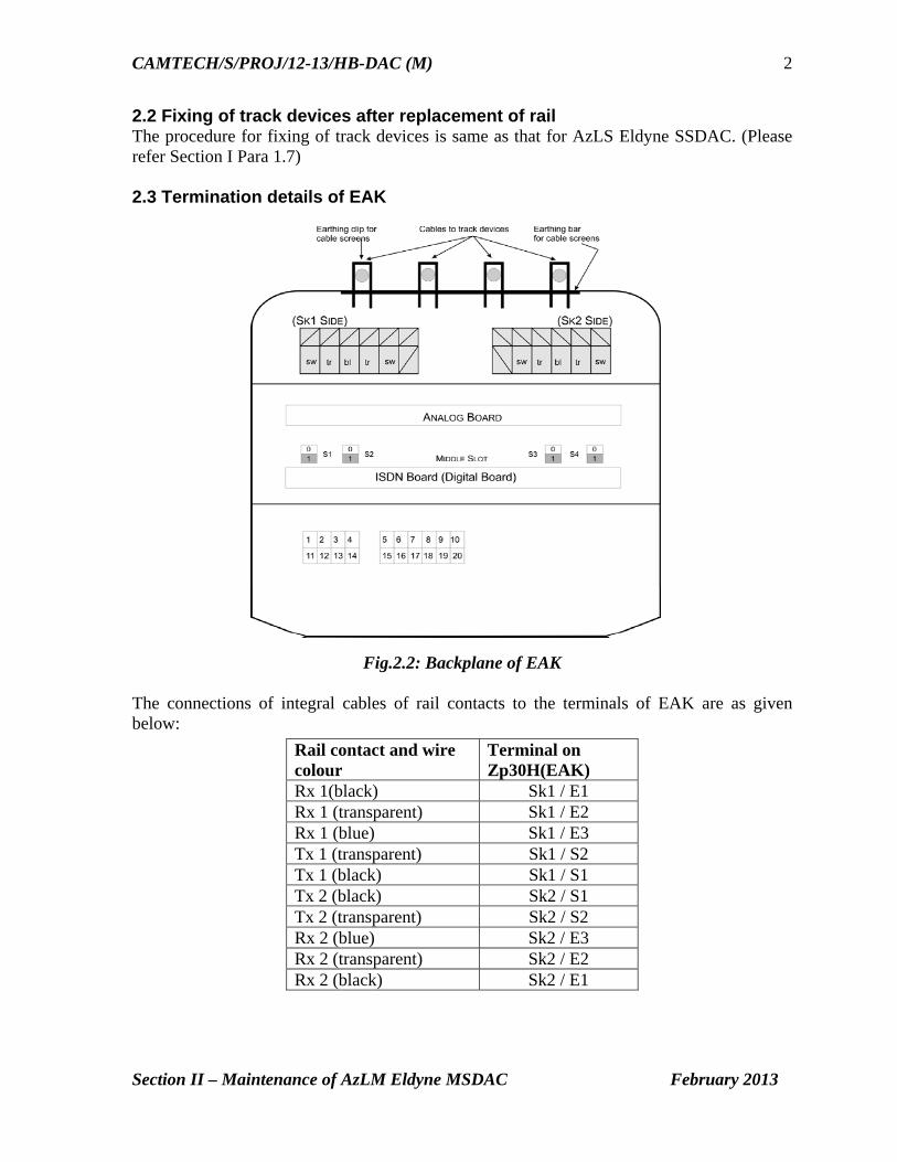
2.2 Fixing of track devices after replacement of rail The procedure for fixing of track devices is same as that for AzLS Eldyne SSDAC. (Please refer Section I Para 1.7) 2.3 Termination details of EAK
Fig.2.2: Backplane of EAK
The connections of integral cables of rail contacts to the terminals of EAK are as given below:
Rail contact and wire colour
Terminal on Zp30H(EAK)
Rx 1(black) Sk1 / E1 Rx 1 (transparent) Sk1 / E2 Rx 1 (blue) Sk1 / E3 Tx 1 (transparent) Sk1 / S2 Tx 1 (black) Sk1 / S1 Tx 2 (black) Sk2 / S1 Tx 2 (transparent) Sk2 / S2 Rx 2 (blue) Sk2 / E3 Rx 2 (transparent) Sk2 / E2 Rx 2 (black) Sk2 / E1

CAMTECH/S/PROJ/12-13/HB-DAC (M)
Section II – Maintenance of AzLM Eldyne MSDAC February 2013
3
The connections for Power Supply/Communication to the EAK are as under:
Connections Terminals Superimposed Power (+) & Data Line 3 Superimposed Power (-) & Data Line 13
Provide a shorting link between terminal 2 & 1 and 12 & 11 if the same pair of conductors is used for superimposed data and power supply to the EAK. If separate power supply is used for installation, the communication line has to be between terminals 3 & 13 and the 60V power supply has to be connected to terminals 1 & 11.
2.4 Evaluator (ACE) Axle Counter Central Evaluator is the decision making unit for multi section digital axle counter. It has the following sub components. CPU card Power Supply Card Serial Card Parallel Card
Fig. 2.3.: Axle Counter Evaluator (ACE) front view CPU Card. Two CPU Cards are required for 2 out of 2 system. Diagnostic interfaces and alphanumeric display are available on CPU Card. Power Supply Card. It works on 24VDC and generates 5VDC and 12VDC required for the electronic circuitry. Two Power Supply Cards are required for 2 out of 2 system.
1 2 1 2 3 4
4
5 5 3
1 Power supply
5 Parallel I/O
5
4
4 4 5
3
4 Serial I/O
3 Covering plate
2 Computer

CAMTECH/S/PROJ/12-13/HB-DAC (M)
Section II – Maintenance of AzLM Eldyne MSDAC February 2013
4
Serial Card receives information from detection points through ISDN communication link and provides this information to CPU Cards. One Serial Card can monitor maximum two detection points. Parallel Card is responsible for providing section information.
Fig. 2.4 : Backplane of Axle Counter Central Evaluator ACE-2-10
U1 & U2 are the connectors for 24VDC Supply to ACE. Polarity of the supply should be checked before connection. The slots S01 to S10 are used for I/O cards, either Serial or Parallel depending upon the site specific software.
Fig. 2.5 : Actual view of backplane of Axle Counter Evaluator (ACE)

CAMTECH/S/PROJ/12-13/HB-DAC (M)
Section II – Maintenance of AzLM Eldyne MSDAC February 2013
5
2.5 Power Data Coupling Unit (PDCU) PDCU is the interface between outdoor equipment (Detection Point) and indoor equipment (ACE). It has a superimposing circuit for using same conductor for power and data. One PDCU is used for one detection point only. There is a 315mA fuse inside the PDCU. The power to the EAK goes through this fuse and if it is blown then there will be no power at detection point and a red LED within the PDCU will glow. PDCUs are to be installed on 35mm DIN rail. Where local power supply is used to feed the EAK, the superimposed power and data is not used. In that case, the PDCU should be used for isolation of communication line and only connector no. 4, 5 and 14, 15 are used.
Fig 2.6.: Connection of PDCU
Fig 2.7: Interconnection between EAK, PDCU & Serial I/O Card

CAMTECH/S/PROJ/12-13/HB-DAC (M)
Section II – Maintenance of AzLM Eldyne MSDAC February 2013
6
2.6 Test equipment (Tool Kit) ETU001 The Test equipment ETU001 is same as that for AzLS. (Please refer Section I Para 1.6).
2.7 Adjustment of Rail contact Tx head with Dummy wheel and Tool Kit The procedure for adjustment of TX head is same as that for AzLS (Please refer Section I Para 1.5).
2.8 Functions of Selector Switch in ETU 001 Functions of Selector switch in ETU 001 are same as given for AzLS (Please refer Section I Para 1.7).
2.9 Parameters to be checked for adjustment of rail contact Outputs of DC-DC Converters, Rx Voltages MESSAB1 & MESSAB2, Reference Voltages PEAGUE1 & PEAGUE2 are checked in the same way as per the procedure given in Section I Para 1.8. The other parameters can be checked as follows:
(i) Axle Counter Evaluator (ACE) Power Supply Voltage range at ACE is 21.5 – 28.8VDC which can be measured at the
connectors U1 & U2 at the backplane of the ACE. Alternatively the input voltage to the ACE can be measured at fuse terminals on CTB.
(ii) Power Data Coupling Unit Check outgoing voltage for trackside connection box at terminal nos. 4 & 5 of PDCU
(iii) Checking Frequency of Tx heads The frequency of the transmitter heads are to be measured by true RMS Multimeter only. For this purpose additional probe set is provided with Tool Kit ETU001. These readings can be taken at connector terminals S1 & S2 of both Sk1 & Sk2 inside EAK.
(iv) Checking of Power supply voltage to Trackside unit EAK Recommended power supply for EAK is 54 – 120 VDC. Measure the power supply voltage fed to the track side electronic unit with the meter and the probe set directly at the power supply connector terminals 1 & 11 if separate pair of conductors is used for 60 V DC power supply and at 3 & 13 if the communication line and 60 V DC power are superimposed in the same pair of conductors.
Fig.2.10: Connector terminals in Trackside Electronic Unit EAK

CAMTECH/S/PROJ/12-13/HB-DAC (M)
Section II – Maintenance of AzLM Eldyne MSDAC February 2013
7
2.10 Adjustment procedure Adjustment procedure is same as that for AzLS.(Please refer Section I Para 1.9)
2.11 Reset Box ERBM-02 is the reset box for AzLM Multi Section Digital Axle Counters. It provides the basic resetting pulse (24VDC) for 3 seconds (approximately) to ACE to reset a particular section. The front panel of the terminal consists of: 1. Push switch 2. Reset counter 3. Preparatory reset indication – GREEN LED 4. Line verification indication – YELLOW LED 5. Section Clear / Unoccupied indication - GREEN LED 6. Section Closed / Occupied indication – RED LED
Fig. 2.11 : Front Panel of Reset Box (ERBM-02)
The SM‘s Key module for multisection reset panel consists of: 1. Reset Key 2. Power On LED Indication (Yellow LED) This Reset Key acts as the common key for all the reset boxes used in a particular installation. Additionally a buzzer is provided to give audio indication that the 3-second reset pulse is on.
Fig. 2.12 : SM’s Key Module

CAMTECH/S/PROJ/12-13/HB-DAC (M)
Section II – Maintenance of AzLM Eldyne MSDAC February 2013
8
2.12 Resetting procedure For resetting AzLM, the following procedure is to be adopted: 1. The authorized person inserts the KEY, turns it clockwise and then pushes. (If optional
Co-operative reset key is provided this has also to be turned simultaneously by another authorized person. For this H & R are to be shorted at selection jumper J1 on PCB. If the cooperation / line verification is not required then P & R are to be shorted).
2. While KEY is in turned position the RESET PUSH BUTTON for a specific section is pressed momentarily.
3. BUZZER sounds for 3 seconds and then stops. 4. The KEY is then turned back anti-clockwise and taken out. A reset operation is only possible when section is occupied or disturbed.
2.13 Check points for maintenance
2.13.1 Outdoor equipment EAK The maintenance check points for outdoor equipment are same as those for AzLS (Please refer section).
2.13.2 Indoor equipment ACE Check the PDCUs are correctly installed on DIN rail and all connections are tight. Check all fans inside the ACE cabinet are working. Check the physical condition of connections in vital relays and snubbing diodes. Check the backplane connections are proper and fuses are properly held. Check all the cards are properly housed in the sub rack. Check that the reset boxes are properly fixed on the base. Check that the reset boxes are properly sealed and no termination is exposed outside. Check that all earth connections are intact and making good contact and earth lead wire,
nut connecting earth wires etc. are not corroded. Check all spare conductors of communication 6/4 quad cable are properly earthed. Check that all the indications of DP on ACE are displaying the normal function. Check the DP profile in the Diagnosis of AzLM system using diagnostic software and
take required action as per diagnostic software report. Measure the earth resistance and paint its value on earth enclosures/nearest wall. If
required take suitable steps to improve the earth resistance. It should be less than 1 Ohm. Check voltage at VR, it should be more than 20 V DC. Remove and replug parallel I/O cards of seldom occupied sections (clear section will
indicate occupied on removal; after re-plugging, will get clear after an internal check.
2.14 Do’s & Don’ts Apart from do’s and don’ts for outdoor equipment which are same as that given for AzLS in section, following precaution should be taken for indoor equipment:
Never plug in or pull out the power supply card and CPU card while the ACE is live. Keep both front and back doors of ACE cabinet properly sealed and locked. Ensure that ACE cabinets are earthed with 25 sq mm copper wire (or its equivalent)
along with lug.

CAMTECH/S/PROJ/12-13/HB-DAC (M)
Section II – Maintenance of AzLM Eldyne MSDAC February 2013
9
2.15 Log Sheet All the measurements should be recorded in the following format: Outdoor Equipment: EAK Date………… Item Permissible range Recorded value Selector position in test unit
1 a) Power supply Channel 1
22…35 VDC
2 b) Power supply Channel 2
22…35 VDC
4 c) ( Rectified Rx1 voltage w/o dummy wheel ) MESSAB1
+80..+1000mV DC
(d) With dummy wheel set on 40 mm
-80..-1000mV DC
5 (e) Reference voltage PEGUE1
Adjust as per (c)
7 (f) ( Rectified Rx1 voltage w/o dummy wheel ) MESSAB2
+80..+1000mV DC
(g)With dummy wheel set on 40 mm
-80….-1000mV DC
Terminal 3 & 13 of EAK
i) Input Power supply voltage 54 V to 72 V DC
Terminal SK1/S1 & SK1/S2
(j) Transmitter frequency SK1 30.0….. 31.25 KHz (k) Transmitter voltage SK1 40……85 VAC
Terminal SK2/S1 & SK2/S2
(l)Transmitter frequency SK2 27.4…..28.6 KHz m)Transmitter voltage SK2 40……85 V AC
Indications Analog board
n) H1-1 Red/H1-2 Green Note (o) H2-1 Red/H2-2 Green Note (p) H3-1 Red/H3-2 Green Note
Indications Digital board
(q) H1-1 Green/H2-1 Green Note (r)H1-2 Green/H2-2 Green Note
(s) Signature Indoor equipment :ACE & PDCUDP & PDCU No.
Date Input Voltage PDCU Voltage Designation & Signature with initials
Remarks
ACE Voltage > 21.5 V DC
Ripple Voltage <10 mV rms
Input to PDCU > 5 V DC
Ripple Voltage < 10 mV rms

Section III
Maintenance of
Siemens Az S 350 U
Multi Section Digital Axle Counter
CAMTECH/S/PROJ/2012-13/HB- DAC(M)
February 2013

Contents
Section III: Maintenance of Az S 350 U Siemens Multi Section Digital Axle Counter
Sr. No. Description Page No.
3.1 Introduction 1
3.2 Outdoor Equipment - ZP 43 Wheel Detection
Equipment 1
3.3 Indoor Equipment - Evaluation Computer 4
3.4 Power Supply 6
3.5 Reset options 6
3.6 Adjusting ZP 43 V Wheel Detection Equipment 7
3.7 Do’s & Don’ts 9
3.8 Adjustments and measurements at Evaluation Computer
10
3.9 Switching the Evaluation Computer On and Off 10
3.10 Replacing Boards 11

CAMTECH/S/PROJ/2012-13/HB-DAC (M)
Section III : Maintenance of AzS350U Siemens MSDAC February 2013
1
Section III Maintenance of
Az S 350 U Siemens Multi Section Digital Axle Counter
3.1 Introduction
Az S 350 U consists of two main components: Outdoor equipment Indoor equipment
The outdoor equipment is the ZP 43 wheel detection equipment. The indoor equipment consists of the evaluation computer. The ZP 43 wheel detection equipment is connected to the indoor equipment via a two-core cable.
EU – Evaluation Unit CH1/2 – Counting head DEK 43 – Double Wheel Detector TCB – Trackside connection box
Fig 3.1.: Basic configuration of Az S 350 U
3.2 Outdoor Equipment
ZP 43 Wheel Detection Equipment ZP 43 is the counting head which comprises a double wheel detector and a trackside connection box. The track section to be monitored is called Track Vacancy Detection Section or TVDS. Counting heads are installed at the limits of a TVDS.

CAMTECH/S/PROJ/2012-13/HB-DAC (M)
Section III : Maintenance of AzS350U Siemens MSDAC February 2013
2
3.2.1 Fixing of track devices after replacement of rail Two holes of 13 mm dia. are to be drilled on rail web as per dimensions shown
below:
Fig.3.2: Top view of ZP43 Double Wheel Detector fitting Fig.3.3: Section of rail
Height X of the hole depends upon the rail profile and shall be as per table given below: Table A
Fig. 3.4.: Double Wheel Detector components
Rail profile 60 Kg 52 Kg 90 lbs Height X 85 mm 69 mm 56 mm Height of new rail 172 mm 156 mm 143 mm Permissible wear & tear 13 mm 8 mm 5mm
1. Inner side of rail 2. Outer side of rail 3. Transmitter 4. M12 Hexagonal nut 5. Spring Washer 6. Square Washer 7. Mushroom head bolt 8. Receiver 9. Reducing plate
Fig.5.1: Drilling of holes on rail web for installation between sleepers

CAMTECH/S/PROJ/2012-13/HB-DAC (M)
Section III : Maintenance of AzS350U Siemens MSDAC February 2013
3
Fig. 3.6.: Terminal Assignment with lightning protection module board in the Trackside Connection Box
Fig.3.7: Lightning Arrester Module connected at rear side of backplane
Fig. 3.5.: Installation of Double
Wheel detector

CAMTECH/S/PROJ/2012-13/HB-DAC (M)
Section III : Maintenance of AzS350U Siemens MSDAC February 2013
4
3.3 Indoor Equipment Evaluation Computer The Evaluation Computer consists of plug-in circuit boards which are accommodated in a single-tier mounting frame with wiring backplane. Dummy boards are inserted in free slots for optional boards.
Fig. 3.8: Front view of Az S 350 U evaluation computer (including slot numbers) 3.3.1Overview of boards SIRIUS2 board Serial computer interface universal board The SIRIUS2 board enables communication between the connected evaluation computers. This board is used on one channel only. On the front panel, there is a 48-pin connector for connection to all interface signals. An optional front connector with two 9-pole sub-D sockets is used for modem connection. A service PC can be directly connected via a two-pole diagnostic socket.
BLEA12 board Block input / output board with 12 relay outputs All inputs and outputs to and from the interlocking are done via the BLEA12 block input /output board. It has 12 floating relay outputs and 12 floating opto-coupler inputs. Inputs and outputs are made via a 48-pin connector on the front panel of the board. The four buttons (T1 to T4) on the front connector of the first pair of BLEA12 boards permit connection of the auxiliary axle count reset button (AzGrH).
Fig.3.9: (a) Front view of SIRIUS2 board (b) front connectors with sockets
Fig. 3.10: (a) Front view of BLEA12 board (b) Front connector with buttons

CAMTECH/S/PROJ/2012-13/HB-DAC (M)
Section III : Maintenance of AzS350U Siemens MSDAC February 2013
5
STEU board Control and diagnostic board The STEU board buffers the signals transmitted by the counting heads. There is one STEU board per channel. The LEDs on this board display the following: Normal display: display of the operating states of the four track vacancy detection
sections (during operation; operating state display) Statistics display (diagnostics): display of operating states for a certain counting
head or track vacancy detection section (switchover / selection via AzGrH button) Display after emergency shutdown: display of operating states in case of emergency
shutdown VESBA board Amplifier, trigger and band-pass filter board Each directly connected counting head requires one VESBA board. It provides electrical isolation between indoor and outdoor equipment (counting head). The VESBA board splits the signal frequencies f1 and f2 into two independent channels and filters, amplifies, rectifies and evaluates (trigger) the data transmitted from the counting head. VAU board Processing & Monitoring board
The VAU processing and monitoring board, a CPU board, constitutes the failsafe microcomputer system (SIMIS C computer core). It provides monitoring and comparator functions for synchronous dual-channel microcomputer operation. Table B Fig.3.11: Front view of VAU board
DIGIDO board Digital double-usage board The DIGIDO digital double-usage board is used if WDE information is to be jointly used by two evaluation computers SVK2150 board Power supply board The SVK2150 power supply board provides 5 V for the evaluation computer and 70 V for the counting heads. The SVK2150 board transforms the interlocking voltage into controlled voltages (5 V DC for computers, 12 V DC (used for predecessor systems only) and 70 V DC for counting heads).
Indication Description VGL(Yellow LED) Comparator SPW (Red LED) Voltage Controller PAB (Red LED) Program-controlled shutdown ANL (Red LED) Start-up Red button System reset

CAMTECH/S/PROJ/2012-13/HB-DAC (M)
Section III : Maintenance of AzS350U Siemens MSDAC February 2013
6
3.4 Power Supply Following power supplies are required for functioning of the Axle Counter equipment:
5 V DC for internal operation 70 V DC for external operation of max. five counting heads
The counting heads can also be supplied with power directly from an on-site external voltage source via an additional band-pass filter board (in the ZP 43 WDE). 3.5 Reset Options For resetting of Az S 350 U two methods are used for resetting the system:
Immediate axle count reset Preparatory axle count reset
3.5.1 Immediate axle count reset With this type of reset, the track vacancy detection section is immediately indicated as being clear after the axle count reset button (AzGrT) has been pressed, provided that no reset restriction (RR) is active. A reset restriction is active if the last axle registered by the axle counting system has been ‘counted in’. If a reset restriction is active, operation of the AzGrT button has no effect. The reset restriction can be cancelled by a relief operator action using the auxiliary axle count reset button (AzGrH). Actuation of the AzGrT button must be in conjunction with co-operation (by pressing and turning line verification key) from another agency after verifying that the track section in question is clear. 3.5.2 Preparatory axle count reset With this type of reset, the track vacancy detection section in question is not immediately indicated as being clear after pressing the preparatory axle count reset button (vAzGrT). It only causes the axle count of the track vacancy detection section to be reset to 'zero'. A clear indication is issued only after passage of a subsequent train over the track vacancy detection section by piloting. 3.5.3 Technical requirements for Successful AzGrT or vAzGrT Operation A successful reset of a track vacancy detection section (TVDS) requires that no reset restriction (RR) is effective.
Fig.3.12: Front view of SVK2150 board

CAMTECH/S/PROJ/2012-13/HB-DAC (M)
Section III : Maintenance of AzS350U Siemens MSDAC February 2013
7
3.5.4 Reset restriction Depending on the configuration, the reset restriction is set according to different parameters. There might be a reset restriction, if one of the following is true: Pulse detection by a counting head belonging to the TVDS: There is an axle on or oscillating over the double wheel detector. The power supply of the counting heads is faulty. The double wheel detector or double wheel detector cable connections are faulty. Counting heads of the TVDS have been traversed within the last six seconds. The last test of switching capability (internal software test – SOPP) of the data
channels on the VAU board has not been successful. The axle last recorded by the evaluation computer in a track vacancy detection
section is an axle counted in. 3.6 Adjusting ZP 43 V Wheel Detection Equipment 3.6.1Tools and Test Equipment required for adjustment
Open-end, ring or box spanner, width across flats 13 Screwdriver 0.6 x 2.8 as per DIN 7437 Screwdriver 0.6 x 3.5 as per DIN 7437 Test equipment: Probe adapter board and multi-meter (Fluke-189 or equivalent)
with measuring ranges. 3.6.2 Probe Adapter Board The probe adapter board SCN S25552-B43-D1 can be used during commissioning and maintenance for testing and adjusting work on the ZP 43 V WDE. Adjusting work (voltage and frequency measurements) can be performed using a commercially available multi-meter. Measuring sockets arranged in pairs are provided on the front panel (Refer Fig. 3.13 on page 8). The multi-meter is connected to these measuring sockets. 3.6.3 Multimeter Requirements The multi-meter (Fluke-189 or equivalent) must meet the following requirements: DC measuring range: 300 mV to 100 V AC measuring range: 40 mV to 100 V Frequency measuring range: 2.5 kHz to 45 kHz 3.6.4 Procedure for measurement/adjustment Remove all stray metal parts (e.g. tools) in the vicinity of the double wheel detector. Plug the test adapter board into the connector provided on the backplane. Set the required AC/DC range on the multi-meter. Connect the probes of multi-meter to the relevant measuring sockets provided on the
front panel of test adapter board. Take the measurements and adjust the parameters if required as follows:
(a)Checking Wheel Detection Equipment Supply Voltage U60 The voltage at the measuring sockets U60 must be between 30 V DC and 72 V DC.
(b)Checking Wheel Detection Equipment Voltage U24 The voltage at the measuring sockets U24 must be between 21.3 V DC and 22.4 V
DC. This is the internal, stabilized supply voltage of the wheel detection equipment.

CAMTECH/S/PROJ/2012-13/HB-DAC (M)
Section III : Maintenance of AzS350U Siemens MSDAC February 2013
8
(c)Setting 43 kHz Transmitter Frequency Set the transmitter frequency using the rotary switch on the backplane to 43 kHz as
precisely as possible. This frequency value is measured at the sockets FS. It must be within the tolerance range of 42.8 kHz to 43.2 kHz.
(d) Measuring Standard Voltage UR1
The DC voltage at the sockets UR1 is measured after adjusting the signal frequencies f1 and f2 as given below. This value must be within the range of 3.45 V to 3.65 V DC.
(e)Measuring Standard Voltage UR2
The DC voltage at the sockets UR2 is measured after adjusting the signal frequencies f1 and f2 as given below. This value must be within the range of 3.25 V to 3.45 V.
(f) Setting Signal Frequency f1
Measure the frequency value f1 at the sockets f1. Slowly adjust the potentiometer f1 on the front of the generator board (slot 4) to the signal frequency of 3.50 kHz using a 0.6 x 2.8 mm screwdriver (tolerance range 3.47 kHz to 3.53 kHz).
(g)Setting Signal Frequency f2
Measure the frequency value f2 at the sockets f2. Slowly adjust the potentiometer f2 on the front of the generator board (slot 4) to the signal frequency of 6.37 kHz using a 0.6 x 2.8 mm screwdriver (tolerance range 6.31 kHz to 6.43 kHz).
(h)Checking Receiver Voltages UE1 and UE2
Measure the receiver voltage UE1 at the sockets UE1. Measure the receiver voltage UE2 at the sockets UE2. The voltage indicated is the voltage which is coupled into the receiver coils of the receiver by the 43 kHz transmitter via the rail. This voltage ranges from 60 mV AC to 150 mV AC. The receiver voltage must not be lower than 60 mV.
Fig. 3.13 : Front panel of the probe adapter board

CAMTECH/S/PROJ/2012-13/HB-DAC (M)
Section III : Maintenance of AzS350U Siemens MSDAC February 2013
9
Table C: Electrical parameters of ZP 43 V Wheel Detection Equipment Parameter Description Standard value Tolerance range
U60 WDE voltage 60 V DC 30 V to 72 V U24 Operating voltage 24 V DC 21.3 V to 22.4 V FS Transmitter frequency of
the double wheel detector43 kHz 42.8 kHz to 43.2 kHz
F 1 Signal frequency 1 3.50 kHz 3.47 kHz to 3.53 kHz F 2 Signal frequency 2 6.37 kHz 6.31 kHz to 6.43 kHz Ur1 Standard voltage 1 3.55 V DC 3.45 V to 3.65 V Ur2 Standard voltage 2 3.35 V DC 3.25 V to 3.45 V uE 1 Receiver voltage 1 AC 60 mV to 150 mV uE 2 Receiver voltage 2 AC 60 mV to 150 mV
Fig.3.14: ZP 43 V Wheel Detection Equipment potentiometers for adjustment 3.7 Do’s & Don’ts The MOS components mounted on the circuit boards of the wheel detection equipment can be damaged by electrostatic discharge from charged persons or equipment. When handling these boards, the following rules must be observed: All parts of the wheel detection equipment may be carrying an interference voltage.
Therefore, always connect the measuring leads for connecting the probe adapter board and the measuring equipment to the measuring equipment first and then insert them into the measuring sockets of the probe adapter board.
Do not touch any metal parts of the measuring leads if they are connected to the wheel detection equipment.
Hold the boards only by the long sides (guide edges), front panel, locking or designation plate holder.
Keep the boards in their original protective packaging until they are installed in the wheel detection equipment.
Do not touch circuit board terminals, conductors, components or plug connectors. In all adjustment work, the double wheel detector must be in the uninfluenced state
(no wheels or other metal objects in the vicinity).

CAMTECH/S/PROJ/2012-13/HB-DAC (M)
Section III : Maintenance of AzS350U Siemens MSDAC February 2013
10
3.8 Adjustments and measurements at Evaluation Computer On the front panel of each VESBA board, there are measuring sockets for fault diagnostics as well as LEDs for displaying the state of passage and a potentiometer for adapting to different cable lengths and setting the transmission level.
Sr. No.
Parameter Acceptable Range Observed Values CH1 CH2 CH3 CH4 CH5 CH6
1 Signal F1 2.9 to 3.1 V DC 2 Signal F2 2.9 to 3.1 V DC
Fig. 3.15: Front view of VESBA board
3.9 Switching the Evaluation Computer On and Off
Switching ON Restarting an evaluation computer means switching on all computer channels either for the first time or after a fault. Set the switches of the power supply boards to "I". Simultaneously press the red buttons (system reset) on both VAU boards of both
computer channels for approx. 1 sec., the LED "ANL" must light up on both VAU boards for approx. 3 sec.
After the LED "ANL" on the VAU boards has gone off, the LED "VGL" will light up. During computer start-up, all LEDs 0 to 11 on the STEU boards light up for max. 10
sec. As soon as the LEDs change to normal display, the evaluation computer is operable (LED 0 shows steady light).
When an evaluation computer is restarted, it is guaranteed that all track vacancy detection sections are first indicated as being "occupied" and displayed accordingly. In accordance with the configured reset type (AzGrT or vAzGrT) and the railway regulations the authorised person must then perform the axle count reset. No train movement should be carried out during this procedure.

CAMTECH/S/PROJ/2012-13/HB-DAC
Section III: Maintenance of AzS350U Siemens MSDAC February 2013
11
Switching OFF The evaluation computer may only be switched off in consultation with the SM/ authorised person. For switching OFF a computer for corrective maintenance or long-term shutdown purposes: Set the switch of the power supply board to "0". In case of long-term computer shutdown, the supply voltage must be switched off, do
not exceed the admissible out-of-service period of. 5.5 months (only if supply voltage is switched off immediately after channel failure).
If these times are exceeded, special safety measures must be performed. The evaluation computer may only be put into operation again by Siemens specialist staff.
3.10 Replacing Boards
Only remove or insert boards and front connectors when the computer is in the de-energized state. Removing and inserting boards in the energized state may damage or destroy boards or computer. Removing Boards To remove boards, proceed as follows: Loosen the knurled screws at the upper and lower locking bars of the mounting frame (if present). Remove both locking bars. Loosen front connectors (if present). If the board is supplied with a handle, pull at the handle to remove the board. Remove boards without a handle using the extraction tool. Pull out the board completely. Fig. 3.16 : Extraction tool for boards Inserting Boards To insert boards, proceed as follows: Slightly press up the upper locking bar and insert the board into the mounting frame according to the location diagram. Plug in front connectors (if present) previously prepared and tighten them. Tighten the knurled screws of the locking bars. The VAU board must always be replaced in pairs
Section IV
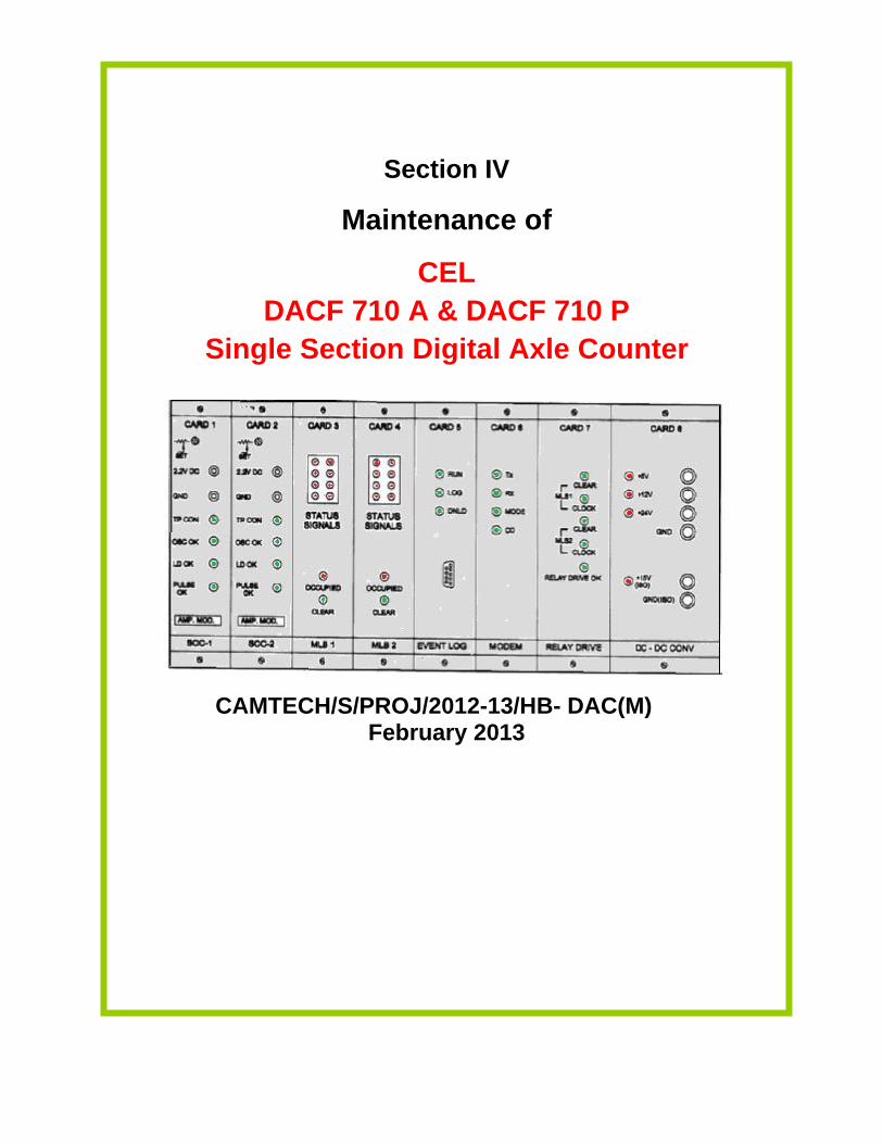
Maintenance of
CEL DACF 710 A & DACF 710 P
Single Section Digital Axle Counter
CAMTECH/S/PROJ/2012-13/HB- DAC(M) February 2013

Contents
Section IV: Maintenance of DACF 710 A & DACF 710 P CEL Single Section Digital Axle Counter
Sr. No. Description Page No.
4.1 Introduction 1
4.2 Components of DACF 1
4.3 Vital Relay box 1
4.4 SM’s Reset box 2
4.5 Surge Voltage Protection Device 2
4.6 Installation of Tx and Rx coils after replacement of rail 2
4.7 LED indications on SSDAC unit 3
4.8 Maintenance 4
4.9 Resetting procedure 8
4.10 Tools & Spares 10
4.11 Do’s & Don’ts 11

CAMTECH/S/PROJ/12-13/HB-DAC (M)
Section IV: Maintenance of DACF 710 A/P CEL SSDAC February 2013
1
Section IV Maintenance of
DACF 710 A & DACF 710 P CEL Single Section Digital Axle Counter
4.1 Introduction
The system comprises of trackside counting units, installed at both ends near the detection points on the track. No separate evaluator is required. Two versions available (i) DACF 710 P (Phase reversal type) The DACF 710 P is not affected by the push trolleys having 4 spoke and 8 spoke wheels; and rail dolly. Trolley suppression track circuit is not required. It counts the following push trolleys: (a) Push trolley with perforated wheel; (b) Dip lorry and (c) Motor trolley. (ii) DACF 710 A (Amplitude Modulation type) The SSDAC remains unaffected with all types of insulated push trolleys but goes into disturbed state (ERROR condition) for non insulated trolleys. Trolley suppression track circuit is required.
4.2 Components of DACF The CEL DACF system consists of following units Axle detectors Transmitter (TX) coils – 2Nos. fed with 21 kHz and 23 kHz carrier signals
Receiver (RX) coils – 2 Nos. to receive the transmitter signal The Rx signal is phase modulated with each train wheel passing over the detection point. Trackside electronic unit (SSDAC) The SSDAC unit comprises total 8 cards namely: Card No.1 & 2 - Signal Conditioning Card
Card No.3 & 4 - Micro controller logic blocks (2 Micro controllers)
Card No. 5 - Event Logger Card
Card No. 6 - Modem Card
Card No. 7 - Relay Driver Card
Card No. 8 - Power Supply Module (DC-DC converter)
4.3 Vital relay box
The VR box consists of dual relay i.e VR & PR relay of Q style, 24V and 1000 ohm. It is provided in the trackside location box along with SSDAC unit.
Fig. 4.1: Vital Relay Box

CAMTECH/S/PROJ/12-13/HB-DAC (M)
Section IV: Maintenance of DACF 710 A/P CEL SSDAC February 2013
2
4.4 SM’s Reset Box - 1 No. for common resetting (when used in station area/platform lines)
- 2 Nos. for independent resetting (when used in block sections) The reset box consists of the following:
i. The LED indications Section Clear - Green indication. Section Occupied - Red indication. Power ON - Yellow indication. Preparatory Reset - Green indication. Line Verification – Yellow indication.
ii. SM’s key actuator. iii. Reset Push button (Red colour). Fig. 4.2: SM’s Reset Box iv. Counter for recording the number of reset operations. v. 20 X 2 LCD display with backlit. vi. 4 keys keypad for setting the date and time operation.
vii. 9 pin D-sub connector on the motherboard of reset box, used for downloading the data for analysis purpose.
4.5 Surge Voltage Protection Device
This Surge Voltage Protection Device is provided to protect the equipments from surge voltages. This device is to be installed at each location along with every SSDAC unit.
Fig. 4.3: Surge Voltage Protection Device 4.6 Installation of Tx and Rx coils after replacement of rail
Marking and drilling holes on web of rail 3 holes of 14 mm dia.on the rail web 0-170-340 mm at 86 mm from top for 90R rail and 88 mm. from the top for 52 Kg/60Kg. rail.
Fig.4.4: Fixing of Marking Jig. Marking using punching guide as per rail size
Fig. 4.5 : Marking Jig, Punch and fixing device
CAMTECH/S/PROJ/12-13/HB-DAC (M)
Section IV: Maintenance of DACF 710 A/P CEL SSDAC February 2013
3
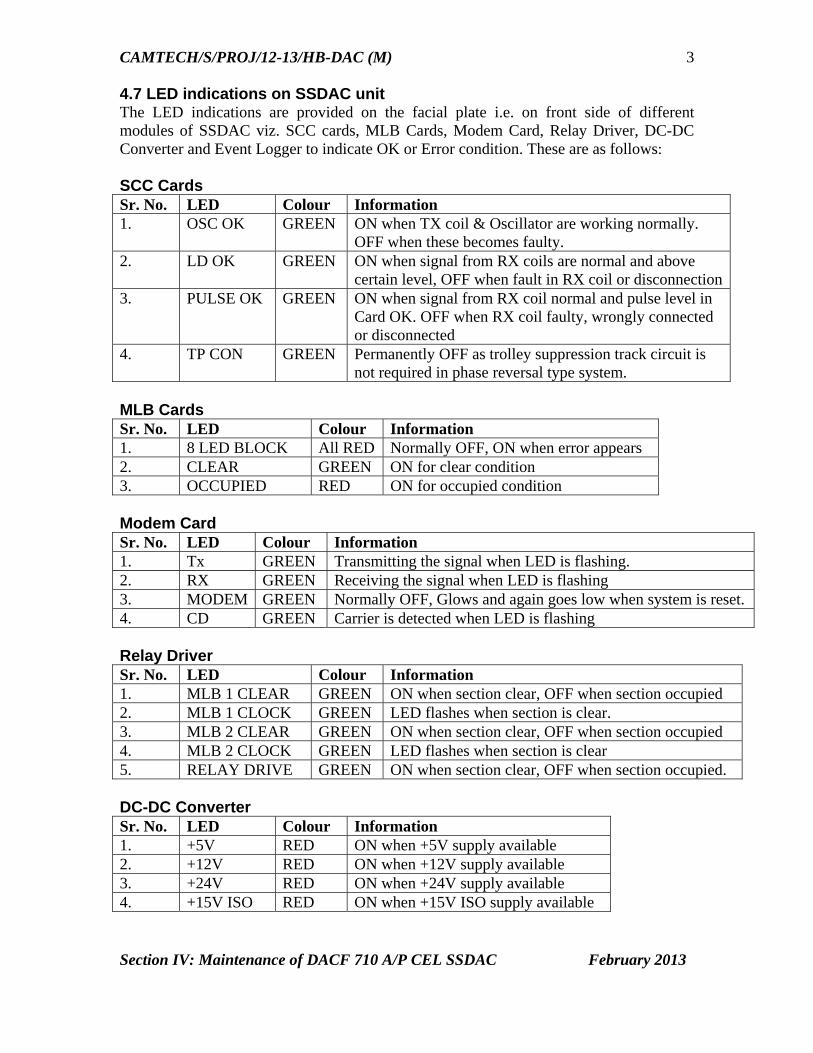
4.7 LED indications on SSDAC unit The LED indications are provided on the facial plate i.e. on front side of different modules of SSDAC viz. SCC cards, MLB Cards, Modem Card, Relay Driver, DC-DC Converter and Event Logger to indicate OK or Error condition. These are as follows: SCC Cards Sr. No. LED Colour Information 1. OSC OK GREEN ON when TX coil & Oscillator are working normally.
OFF when these becomes faulty. 2. LD OK GREEN ON when signal from RX coils are normal and above
certain level, OFF when fault in RX coil or disconnection3. PULSE OK GREEN ON when signal from RX coil normal and pulse level in
Card OK. OFF when RX coil faulty, wrongly connected or disconnected
4. TP CON GREEN Permanently OFF as trolley suppression track circuit is not required in phase reversal type system.
MLB Cards Sr. No. LED Colour Information 1. 8 LED BLOCK All RED Normally OFF, ON when error appears 2. CLEAR GREEN ON for clear condition 3. OCCUPIED RED ON for occupied condition Modem Card Sr. No. LED Colour Information 1. Tx GREEN Transmitting the signal when LED is flashing. 2. RX GREEN Receiving the signal when LED is flashing 3. MODEM GREEN Normally OFF, Glows and again goes low when system is reset. 4. CD GREEN Carrier is detected when LED is flashing Relay Driver Sr. No. LED Colour Information 1. MLB 1 CLEAR GREEN ON when section clear, OFF when section occupied 2. MLB 1 CLOCK GREEN LED flashes when section is clear. 3. MLB 2 CLEAR GREEN ON when section clear, OFF when section occupied 4. MLB 2 CLOCK GREEN LED flashes when section is clear 5. RELAY DRIVE GREEN ON when section clear, OFF when section occupied. DC-DC Converter Sr. No. LED Colour Information 1. +5V RED ON when +5V supply available 2. +12V RED ON when +12V supply available 3. +24V RED ON when +24V supply available 4. +15V ISO RED ON when +15V ISO supply available
CAMTECH/S/PROJ/12-13/HB-DAC (M)
Section IV: Maintenance of DACF 710 A/P CEL SSDAC February 2013
4
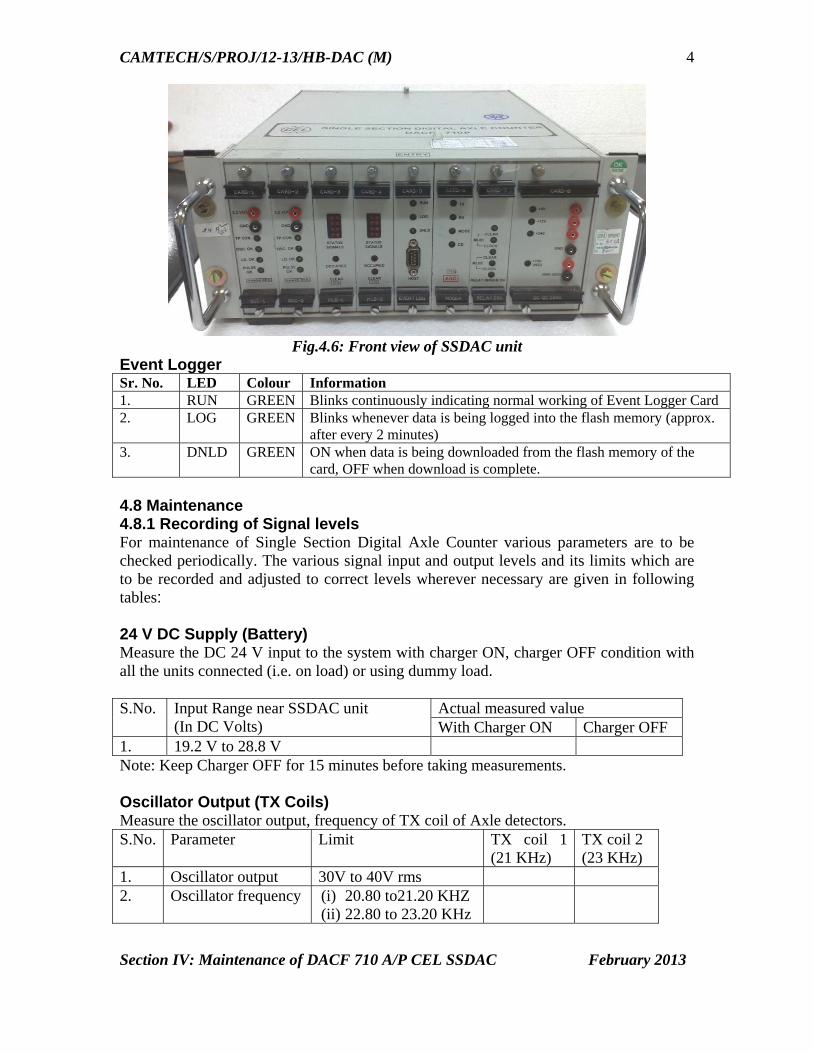
Fig.4.6: Front view of SSDAC unit
Event Logger Sr. No. LED Colour Information 1. RUN GREEN Blinks continuously indicating normal working of Event Logger Card 2. LOG GREEN Blinks whenever data is being logged into the flash memory (approx.
after every 2 minutes) 3. DNLD GREEN ON when data is being downloaded from the flash memory of the
card, OFF when download is complete. 4.8 Maintenance 4.8.1 Recording of Signal levels For maintenance of Single Section Digital Axle Counter various parameters are to be checked periodically. The various signal input and output levels and its limits which are to be recorded and adjusted to correct levels wherever necessary are given in following tables: 24 V DC Supply (Battery) Measure the DC 24 V input to the system with charger ON, charger OFF condition with all the units connected (i.e. on load) or using dummy load. S.No. Input Range near SSDAC unit
(In DC Volts) Actual measured value With Charger ON Charger OFF
1. 19.2 V to 28.8 V Note: Keep Charger OFF for 15 minutes before taking measurements. Oscillator Output (TX Coils) Measure the oscillator output, frequency of TX coil of Axle detectors. S.No. Parameter Limit TX coil 1
(21 KHz) TX coil 2 (23 KHz)
1. Oscillator output 30V to 40V rms 2. Oscillator frequency (i) 20.80 to21.20 KHZ
(ii) 22.80 to 23.20 KHz

CAMTECH/S/PROJ/12-13/HB-DAC (M)
Section IV: Maintenance of DACF 710 A/P CEL SSDAC February 2013
5
Receiver Coil Output Measure the RX coil signal output with and without dummy wheel.
Fig 4.7: Adjustment of Receiver coil with the help of dummy wheel
For Amplitude Modulation type Digital Axle Counter S.No. Parameter Signal Limit
mV rms Signal Measured Value
Dip 15% of signal (mV rms)
Dip measured value
1. RX Coil 1 (21 KHz) 750 - 1200 2. RX Coil 2 (23 KHz) 750 - 1200
Fig 2.9 : Dummy wheel setting = 44 mm for 90 R, 52 kg and 60- kg rails

CAMTECH/S/PROJ/12-13/HB-DAC (M)
Section IV: Maintenance of DACF 710 A/P CEL SSDAC February 2013
6
For Phase Reversal type Digital Axle Counter S.No. Parameter Limit mV rms Measured Value 1. RX Coil 1 (21 KHz) 275 - 600 2. RX Coil 2 (23 KHz) 275 - 600 SCC Cards (Cards 1 & 2) Measure the DC voltages at monitoring sockets of SCC cards 1 & 2 with respect to ground.
Modem Output (Card 6) Check and record the modem signal output of SSDAC during normal working condition of the system.
S.No. Measuring Limit (mV rms) Measured Output (mV rms) 1. >400 mV (-6 dB)
Relay Drive (Card 7) Check and record Relay drive output to the Vital Relay with section clear and section occupied condition. (This may be checked across R1 & R2 of relay coil in vital relay box).
S.No. Parameter Measuring Limit (DC volts) Measured output (DC volts) 1. Clear mode >20 V 2. Occupied mode <2 V
S. No.
Card Measured output voltage (DC volts) Without dummy wheel
With dummy wheel
With push trolley (4/8 spokes) on axle detectors
Limit Meas-ured value
Limit
Meas-ured value
Limit Meas-ured value
1. SCC1
2.0 to 2.5 V
<0.7 >1.7 V
2. SCC2
2.0 to 2.5 V
<0.7 >1.7 V
Fig 4.8.: Front view of SCC 1 Card
CAMTECH/S/PROJ/12-13/HB-DAC (M)
Section IV: Maintenance of DACF 710 A/P CEL SSDAC February 2013
7
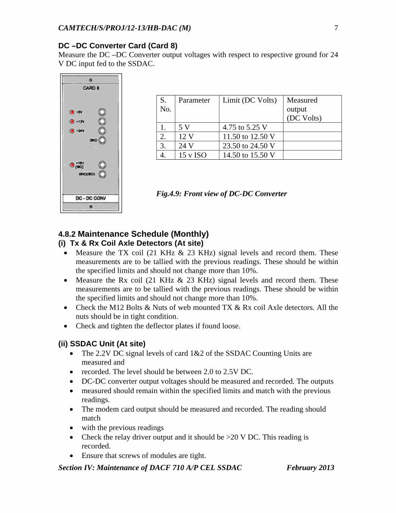
DC –DC Converter Card (Card 8) Measure the DC –DC Converter output voltages with respect to respective ground for 24 V DC input fed to the SSDAC.
4.8.2 Maintenance Schedule (Monthly) (i) Tx & Rx Coil Axle Detectors (At site) Measure the TX coil (21 KHz & 23 KHz) signal levels and record them. These
measurements are to be tallied with the previous readings. These should be within the specified limits and should not change more than 10%.
Measure the Rx coil (21 KHz & 23 KHz) signal levels and record them. These measurements are to be tallied with the previous readings. These should be within the specified limits and should not change more than 10%.
Check the M12 Bolts & Nuts of web mounted TX & Rx coil Axle detectors. All the nuts should be in tight condition.
Check and tighten the deflector plates if found loose.
(ii) SSDAC Unit (At site) The 2.2V DC signal levels of card 1&2 of the SSDAC Counting Units are
measured and recorded. The level should be between 2.0 to 2.5V DC. DC-DC converter output voltages should be measured and recorded. The outputs measured should remain within the specified limits and match with the previous
readings. The modem card output should be measured and recorded. The reading should
match with the previous readings Check the relay driver output and it should be >20 V DC. This reading is
recorded. Ensure that screws of modules are tight.
S. No.
Parameter Limit (DC Volts) Measured output (DC Volts)
1. 5 V 4.75 to 5.25 V 2. 12 V 11.50 to 12.50 V 3. 24 V 23.50 to 24.50 V 4. 15 v ISO 14.50 to 15.50 V
Fig.4.9: Front view of DC-DC Converter

CAMTECH/S/PROJ/12-13/HB-DAC (M)
Section IV: Maintenance of DACF 710 A/P CEL SSDAC February 2013
8
Ensure that MS circular connectors are tight.
(iii) Power Supply (Battery Room & Site) The 24V DC power supply should be measured and recorded. The 24V DC
should remain within specified limits. Inspect the battery charger and check its charging current and ensure it is properly charging the battery. Any interference with power supply and connections of SSDACis likely to cause
failure. This should be done only after ensuring that no train is occupying or approaching
the section.
(iv) Inspection of Reset Box (SM’ s room) Monitor the reset box while the train is occupying the section. The occupied (red) LED should be glowing. When the train clears the section, the clear LED (green) glows. The Reset to the system is controlled through the key actuator & Reset button of reset box. This should not be disturbed. The LCD displays all the information regarding the system. (Please refer
Handbook on Troubleshooting of Digital Axle Counter Section IV) (v) General
Check all the cable connections on the CTboard of apparatus case at both locations.
Ensure that these are in tight condition. Check the deflector plates of the Axle detectors are in normal position. If found
loose this should be properly tightened. (vi) Repair of Faulty Cards
Before declaring any card is faulty, the fault should be analysed and confirmed. Repair of cards is a highly technical job and is not possible at site. Hence
Railways should not carry it out. The card should be sent to CEL for repair.
4.9 Resetting Procedure 4.9.1 In station area
Common resetting The common resetting of both SSDAC units is to be carried out when used in station area for platform lines, yard lines etc. Last vehicle (LV) proving is used in conjunction with reset box if required. Resetting operation Insert SM’s key, turn right and keep pressed. Press Reset button for 2 seconds.

CAMTECH/S/PROJ/12-13/HB-DAC (M)
Section IV: Maintenance of DACF 710 A/P CEL SSDAC February 2013
9
Release SM’s key and Reset Button. Turn left, remove SM’s key and keep in safe custody.
With the above operation 48 V DC from reset box is extended to SSDAC unit. Reset command is generated in MLB1 and MLB2 cards (Cards 3 & 4). The SSDAC units are reset and counts become zero. The SSDAC units attain the preparatory reset state. The PR & PPR relays pick up and Prep. Reset indication glows on the reset
box. The reset counter reading increments by 1 count. After one pilot train is passed in the section the system becomes normal. Vital Relay picks up. Note: Reset command to Micro-controllers will not be generated if system is in clear/preparatory/occupied state. System can be resetted if it is in error state or out counts were registered after occupied state.
4.9.2 In Block Section
Independent resetting The independent resetting of SSDAC units at each station is to be carried out when used in Block Sections. Sometimes SM’s key and button contacts are extended to a remote location for resetting purpose.
Resetting operation Insert SM’s key, turn right and keep pressed. Press Reset button for 2 seconds. Preparatory LED starts flashing. Release SM’s key and Reset Button. Turn left, remove SM’s key and keep in safe custody. With the above operation 48 V DC from reset box is extended to SSDAC unit. Reset command is generated in MLB1 and MLB2 cards (Cards 3 & 4). The SSDAC units are reset and counts become zero. The SSDAC units attain the preparatory reset state. The PR & PPR relays pick up and Prep. Reset indication glows on the reset
box. The reset counter reading increments by 1 count. After one pilot train is passed in the section the system becomes normal. Vital Relay picks up.

CAMTECH/S/PROJ/12-13/HB-DAC (M)
Section IV: Maintenance of DACF 710 A/P CEL SSDAC February 2013
10
Note: Reset command to Micro-controllers will not be generated if system is in clear/preparatory/occupied state. System can be resetted if it is in error state or out counts were registered after occupied state. Resetting operation by both stations is required and is necessary in BPAC use.
4.10 Tools and Spares The following tool kit and spares are required for installation and maintenance:
Tool Kit
1. Portable data analyzer for downloading event logger data for analysis and report generation. (Specification ref: RDSO letter No. STS/E/AC/DIGITAL/CEL dated 19.12.2006.
1 No.
2. Pure sine wave Digital Multimeter make Fluke model 187/Rishabh model 285/ Kusum Meco model 859CF or equivalent.
1 No.
3. Train simulator, Model TS 267P CEL make 1 No. 4. Extender card (Card No.557) 1 No. 5. Dummy wheel 1 No. 6. Ring spanner 17-19, 24-26 1 No. each7. Open end spanner 17-19, 24-26 1 No. each8. Socket spanner with handle 1 No. 9. Torque wrench (Jaicom JPR65 or equivalent, 88NM) 1 No. 10. Screw driver No. 902 1 No. 11. Screw driver No. 935 1 No. 12. Marking jig for drilling 1 No. 13. Dummy load to check power supply (resistive) 1 No. Recommended Spares
The following spares are to be recommended to be kept for 5 Nos. of working Single Section Digital Axle Counter in a particular section.
1. SCC Cards (Card 1 & 2) 2 Nos 2. MLB Cards (Card 3 & 4) 2 Nos 3. Modem Card (Card6) 1 No 4. Relay driver (Card 7) 1 No. 5. Event Logger Card (Card 5) 2 Nos. 6. DC –DC Converter (Card 8) 1 No. 7. Axle Detectors (AD710) 21 KHz/23KHz (Tx coil) 1 No. 8. Axle Detectors (AD710) 21 KHz/23KHz (Rx coil) 1 No. 9. Hardware for mounting Axle Detectors 1 Set 10. MS circular connectors (6 Nos.) 1 Set 11. Reset box RB -259 1 Set 12. SSDAC unit (housing with mother board, without cards) 1 No. 13. Vital Relay Box with Relay 24 V, 1000 Ohm, Q type 1 No. 14. Surge Voltage Protection Device box (SV – 121) 1 No.

CAMTECH/S/PROJ/12-13/HB-DAC (M)
Section IV: Maintenance of DACF 710 A/P CEL SSDAC February 2013
11
4.11 Do's & Dont’s Do’s
The inter connection drawings are to be followed for connecting the Transmitter & Receiver coils. Tx1 is 21 KHz, Tx2 is 23 KHz & Rx1 and Rx2 coils are 21 KHz & 23 KHz, respectively.
Ensure that Receiver and Transmitter coil cables have been laid in different pipes.
Ensure that both the TX coils & Rx coils are having proper alignment on Rail. Ensure that packing of sleepers with ballast on both sides of Axle detector is
proper. Check that metal sheaths of the outdoor cable are connected to earth at both
ends The recommended cables for wiring of the system at site should be used. The steady Battery voltage 24V should be maintained. The cable connections should not be connected loosely. The M.S Circular connectors of SSDAC are checked and maintained firmly. The SSDAC & Reset box is provided with sealing arrangement. They should
be sealed at site. Resetting should be done only after ensuring that there is no train in the
section
Don'ts Don’t install the Axle detectors near the rail joint (should be more than 6
sleepers away). Don’t install the Axle detectors where the rail is badly worn out. Don’t cut or join the Transmitter / Receiver cables supplied along with the
coil. It would result in change of frequency of signal. Don’t lay the TX and RX coil cables in the same pipe. Don’t use any other outdoor cable other than the recommended cables. Avoid installing the Axle detectors on curve of rail / too much slope of rail to
the possible extent. Don’t remove the cards from SSDAC units under power ON condition of
system. Remove card if necessary after Switching OFF the power to the unit.
Section V
Maintenance of
SSDAC-G36 G.G.Tronics Single Section Digital Axle Counter
CAMTECH/S/PROJ/2012-13/HB- DAC (M) February 2013
Contents
Section V: Maintenance of G36 GG Tronics Single Section Digital Axle Counter
Sr. No. Description Page No.
5.1 Introduction 1
5.2 Modules of G36 SSDAC 1
5.3 Configurations 1
5.4 Relay Box 3
5.5 Reset Box 3
5.6 Fixing of TX/RX coils after rail replacement 4
5.7 Power Supply Arrangement 5
5.8 Protective devices 5
5.9 Maintenance 5
5.10 Resetting procedure 7
5.11 Tools and Spares 9
5.12 Precautions 10
5.13 Do’s & Don’ts 10
5.14 Maintenance Log Sheet for SSDAC – G36 12

CAMTECH/S/PROJ/12-13/HB-DAC (M)
Section V - Maintenance of G-36 G.G. Tronics SSDAC February 2013
1
Section V Maintenance of
SSDAC-G36
G.G.Tronics Single Section Digital Axle Counter
5.1 Introduction SSDAC G36 manufactured by M/s G.G.Tronics India Pvt. Ltd., is a microcontroller based system with 2 out of 2 architecture suited for proving station and block section. 5.2 Modules of G36 SSDAC The hardware and software for all the configurations are same. The main modules for SSDAC-G36 are listed below:
SSDAC unit Reset box Axle Detectors (Tx & Rx coils factory tuned to 21 KHz & 25 KHz with
associated cables of 15 Mtrs.each) 5.3 Configurations SSDAC-G36 units can be installed to work in the following configurations:
Two detection points Single section: In straight line [2DP1S]. Three detection points Single section: In point zone [3DP1S]. Three-detection points for two consecutive sections in a straight line [3DP2S].
(i) SSDAC 2DP1S system
This system is provided with two detection points on straight lines in station or block section. It indicates the section as occupied or clear through a Vital Relay (VR) output. The system consists of Start Fed (SF) and End Fed (EF) units. The SF and EF unit consists of the following modules: Phase detector Card 1 - 21 KHz – 1No. Phase detector Card 2 - 25 KHz – 1 No. Central Processing Unit 1(CPU1) – 1 No. Central Processing Unit 2(CPU2) – 1 No. Communication module – 1No. Relay Drive Module – 1 No. SM-CPU /Event logger module – 1 No. DC/DC Converter – 1 No. LCD display Module

CAMTECH/S/PROJ/12-13/HB-DAC (M)
Section V - Maintenance of G-36 G.G. Tronics SSDAC February 2013
2
LCD alphanumeric display with 4 lines & 20 characters per line is fixed on SF/EF units for providing live display of different status, wheel counts and error messages in plain English for guiding the installation and maintenance staff. Note:
(i). CPU1 & CPU2 have unique addresses. (ii). Communication and relay drive modules are equipped in different positions in SF/EF
units for unique port addressing.
Fig.5.1:2DP1S system layout plans for block section and station section
(ii) SSDAC- 3DP1S System In SSDAC 3DP1S configuration, there will be three SSDAC units i.e. Unit A, Unit B and Unit C can be interfaced using FSK Modem communication. All the other features are similar to that of 2DP1S system.
(iii) SSDAC-3DP-2S System
In this configuration, there will be three SSDAC units i.e. Start Fed, Centre Fed and End Fed units which are interfaced using FSK Modem communication. All the other features are similar to that of 2DP1S system.
Fig. 5.3: 3DP2S system layout plan for two consecutive sections in a straight line
SF: Start Fed, CF: Centre Fed, EF: End Fed EFVR - A : Vital Relay at Sec B for End Fed CFVR - A : Vital Relay for Sec A at Centre Fed PR: Preparatory Relay CFVR - B : Vital Relay for Sec B at Centre Fed SFVR - A : Vital Relay at Sec A for Start Fed)
, Com2 : Communication Card
Station Station Section A Section B
Block Section
DP-SF DP-EFDP-CF
DP-B
DP-C
DP-A
DP-SF DP-EFStation Section
Station
Station Station Block Section
DP-SF DP-EF
Fig.3.2: 3DP1S system layout plan for point zone

CAMTECH/S/PROJ/12-13/HB-DAC (M)
Section V - Maintenance of G-36 G.G. Tronics SSDAC February 2013
3
5.4 Relay Box Relay boxes are provided depending upon the configuration as given below:
Sr. No. Configuration Units Vital relay Preparatory Relay 1. 2DP1S version SF 1 1
EF 1 1 2. 3DP1S version -- 1 -- 3. 3DP2S version SF 1 1
EF 1 1 CF 2 2
5.5 Reset Box
The Reset Box has the following controls and displays.
SM Key – This has a facility of locking to prevent unauthorized operations. For executing a reset command, this key has to be kept pressed after unlocking it. Reset Push Button – This switch is meant for sending the reset command to the system. For sending the reset command, both the SM Key and the reset push button are to be held pressed simultaneously and momentarily. Line Verification Box Line verification Box is supplied only for case where hard reset has to be adopted instead of a preparatory reset.
Indications One 10 mm Green and Red LED are provided for indicating status of block section. One 5 mm green LED for indicating the status of preparatory reset. Flashing- when local reset is applied. Steady - when reset is applied at the other end also & the system is waiting for pilot train. OFF – when the section becomes clear. One 5 mm Yellow LED for indicating the line verification status. Normally OFF; glows only when line verification key is operated for executing direct reset. One 5 m Yellow LED for indicating power ON condition.
Fig. 5.4.: Reset box front view

CAMTECH/S/PROJ/12-13/HB-DAC (M)
Section V - Maintenance of G-36 G.G. Tronics SSDAC February 2013
4
Counter One 6 digit non-resettable counter is provided which increments after each resetting operation. Display One LCD display with 4 lines & 40 characters gives display of events, System Status, Checksum and Version No, Counts and error code. The reset box is connected to the system with one pair of quad cable for FSK communication and 12 core signal cable for transfer of reset commands and reception of the signals from the system.
The reset box required may be one per unit or two per unit depending upon the configurations. Process of resetting required for a particular configuration also differs. For example a single stationmaster or two separate stationmasters can do reset.
SIGNALLING CABLE
FSK QUAD CABLE
Fig. 5.5: Termination details of Reset Box 5.6 Fixing of TX/RX coils after rail replacement Marking & Drilling holes on the Rail The 3 Holes of 13 mm dia. are required to be marked and drilled for fixing web mounted
TX/RX coils at each location with spacing of 183mm. From bottom of the rail drill the holes at 68 mm for 52 Kg, 84 mm for 60 Kg and 57 mm for 90 R. A standard MS jig with pilot holes for marking the drilling of rails of different gauges is provided for the installation of the system. This jig can be fixed on to the bottom of the rails and the track drilling can be marked accurately for fixing Tx/Rx coils.
RESET DETAIL T1 +24V T9 LV FC 1B T2 GND T10 LV FC 2A T3 Prep Relay FC1 T11 LV FC 2B T4 Spare T12 Vital Relay FC2 T5 Vital Relay FC1 T13 Vital Relay BC2 T6 Spare T14 +RESET T7 Spare T15 -RESET T8 LV FC 1A T16 Spare
FSK DETAIL T1 Spare T2 Spare T3 Spare T4 Spare T5 SM Modem FSK T6 SM Modem FSK
T1
T2
T3
T4
T5
T6
T7
T8
T9
T10
T11
T12
T13
T14
T15
T16
T1
T2
T3
T4
T5
T6

CAMTECH/S/PROJ/12-13/HB-DAC (M)
Section V - Maintenance of G-36 G.G. Tronics SSDAC February 2013
5
5.7 Power Supply Arrangement The SSDAC system works on 24V DC supply. This has to be provided by the respective station through power cables. The continuous current drain, requirement of battery and battery charger are as indicated in Table below: S. No. Configuration Continuous
current drain Battery capacity Charger capacity
1. 2DP1S version < 2 Amp. 24 V/40 A.H. – 1 set 5 Amp. – 2 Nos. 2. 3DP1S version < 3 Amp. 24 V/40 A.H. – 1 set 5 Amp. – 1 No. 3. 3DP2S version < 3 Amp. 24 V/40 A.H. – 3 sets 5 Amp. – 3 Nos.
Input supply to be maintained between 22 V and 26 V DC. 5.8 Protective devices The details of protective fuses and surge arrestors are as given below: Table A -Fuses
Path FTB Point Rating Quantity Input 24 V DC Power supply to system 1,2 6.3 Amps 2 Nos. on + limbs Spare 5,6,7,8 6.3 Amps 4 Nos. DC 24 V supply to Relay Box 11,12,13,14 6.3 Amps 4 Nos. Connection from System to Relay box 15 to 22 2 Amps 8 Nos. Connection to VPR & PPR relays in Relay room
23,24,25,26 2 Amps 4 Nos.
Quad cable to system 27,28 2 Amps 2 Nos. To reset box in the station 35,36,43,44 2 Amps 4 Nos. Tx/Rx coil connections 51 to 58 2 Amps 8 Nos.
Table B - LDUs (Lightening Discharge Protection Units)
Path Type Quantity Input 24 V DC Power Supply to System 24 V DC 1 No. Termination of Quad cable to System 24 V DC 1 No. Quad cable from System to Reset Box 24 V DC 1 No. Quad cable from Reset Box to System for reset 48 V DC 1 No.
5.9 Maintenance
Adjustments required in the field The adjustment has to be done after measuring the voltages at monitoring points provided on different modules, tabulated in the Table C. Output voltages of DC-DC Converter Measure the input voltage of 24 V DC between GND and the corresponding input monitoring point; this should be within 22 V and 26 V DC. With the same GND measure the other voltages.

CAMTECH/S/PROJ/12-13/HB-DAC (M)
Section V - Maintenance of G-36 G.G. Tronics SSDAC February 2013
6
Adjust +5V precisely to 5V with the help of potentiometer provided for the purpose on the front plate of DC-DC Converter. Similarly adjust +18V fed to the PD card.
Settings in PD cards for different voltages In the PD cards adjustment facility is provided for Rx signal, Supervisory signal and phase adjustment of Rx with respect to Tx. All the adjustments have to be carried out under no wheel condition and the voltages are to be as indicated in Table D. Adjustments have to be carried out on each of the 21 KHz & 25 KHz PD cards individually. Table C: Monitoring points of SSDAC
Module Monitoring item Measured values range
DC-DC Converter
+5V DC and GND 4.75V to 5.25 V +18V DC and GND 17.75V to 18.25 V +12V DC and GND 11.75V to 12.25 V -12V DC and GND 11.75V to 12.25 V +24V DC and GND 22V to 26V
CPU1 EN1B O/P and GND (For SF, CF, 3DP1S units)
11.5V to 12.5V DC
EN1A O/P and GND (For EF, CF) 11.5V to 12.5V DC CPU2 EN2B O/P and GND
(For SF, CF, 3DP1S units) 11.5V to 12.5V DC
EN2A O/P and GND (For EF, CF) 11.5V to 12.5V DC RELAY DRIVE 1 (For EF,CF)
VITAL RELAY A O/P(+) VITAL RELAY A O/P(-)
>20V DC
RELAY DRIVE (For SF,CF,3D units)
VITAL RELAY B O/P(+) VITAL RELAY B O/P(-)
>20V DC
Table D – Settings of PD cards Module Monitoring point Expected values
Without wheel With wheel Phase Detector (PD1 and PD2)
RX-SIG and GND (Rx Adj.) 900 mV to 1.2 V AC < 350 mV AC SUP-OUT and GND 4V to 5V DC 3 V to 3.9 V DC WHEEL-M-OUT and GND 4.5V to 5V DC 3 mV to 5 mV DC WHEEL-S-OUT and GND 4.5V to 5V DC 3 mV to 5 mV DC RX-PH-SIG and GND (PH Adj.)
10V to 12V DC 0.1 or 0.2 V (Min.)
SUP-ADJ and GND (SUP Adj.)
4V to 5V DC 3 V to 3.9 V DC
Wheel influencing both detectors
-- < 2 V in both PD cards
Note: (i) The above monitoring points should be checked monthly.

CAMTECH/S/PROJ/12-13/HB-DAC (M)
Section V - Maintenance of G-36 G.G. Tronics SSDAC February 2013
7
(ii) For measuring AC voltages of Tx/Rx coils and at Phase Detector terminals, it is essential that a true RMS voltmeter with Digital Multi-meter of 100 kHz bandwidth like Fluke model 187 or higher and their equivalents of other manufacturers is used for getting proper readings.
(iii) Presence of train wheel condition is to be created with the help of dummy wheel. Maintenance schedule specified by manufacturer
Schedule Maintenance Daily NIL Weekly NIL Monthly Check and record the readings of Power
Supply module and PD module and check the Tx/Rx coil voltages as per the log sheet
Half yearly Replace if any parts broken 5.10 Resetting Procedure
The procedure for reset for the different configurations is described in the following paragraphs. The reset box is wired to SSDAC system through a repeater relay named as VPR. The repeater relay in the relay room repeats the status of the vital relay of the SSDAC system. For all SSDAC system configurations the same reset circuit can be used.
(i) Reset procedure for 2DP1S system The SSDAC-2DP1S system allows reset from stationmaster whenever system is powered on or system/section enter error mode or unbalanced with occupied LED glowing, but no hardware failures. SSDAC-SF and SSDAC-EF need reset from station A and station B. Under this condition, reset is possible only if preparatory and vital relay are in de-energize/drop state. The following procedure is adopted for resetting a 2DP1S system: Stationmaster A inserts and turns the SM key and press the reset button
simultaneously. Preparatory LED start blinking and LCD displays “Reset Applied“ in the position of
remote DP status indicating that reset is pressed. Stationmaster B inserts and turns the SM key and presses the reset button
simultaneously. After SSDAC-SF and SSDAC-EF communication is successful both the systems
enter the preparatory mode with preparatory LED glowing in the reset box at station A and station B and the counter gets incremented by 1.
The LCD display’s “Wait For Pilot Train” in both Local and remote DP status position.
Now the pilot train is allowed in the section to balance the section. On successful piloting of train with minimum of two axles as Incounts and Out-counts, section gets balanced.

CAMTECH/S/PROJ/12-13/HB-DAC (M)
Section V - Maintenance of G-36 G.G. Tronics SSDAC February 2013
8
The section goes through reset operation and vital relays of SSDAC-SF and SSDAC–EF energize/pickup. Occupied LEDs goes off and clear LEDs glow at both station A and station B.
Reset procedure is now completed and SSDAC-2DP1S section is ready for train movements.
(ii) Reset Procedure for 3DP1S (Hard Reset)
SSDAC-3DA, SSDAC-3DB and SSDAC-3DC will need reset from station. The following procedure is adopted for resetting a 3DP1S system: Stationmaster physically verifies that the section is clear and operates line verification switch and line verification LED glows in the reset box indicating that there is no train in the section. Stationmaster inserts and turns the SM’s key and presses the reset button simultaneously. SSDAC-3DP1S Unit A, SSDAC-3DP1S Unit B and SSDAC-3DP1S Unit C system goes through the reset operation and vital relay picks-up/energizes. Counter gets incremented by 1. Occupied LED switch off and clear LED glows. Reset procedure is now completed and SSDAC-3DP1S section is in balanced mode ready for train movements.
(iii) Reset Procedure for 3DP-2S (Preparatory Reset)
SSDAC-SF, SSDAC-CF and SSDAC-EF need reset from station A and station B. Under this condition, reset is possible only if preparatory and vital relay are de-energize/drop. The following procedure has to be followed: Reset Procedure for Section A Station A stationmaster insert and turns the SM key and presses the reset button of
reset box in station A simultaneously for section A. Now, Preparatory LED starts blinking indicating that reset is initiated at station A for
section A. Station B stationmaster insert and turns the SM key and presses the reset button
simultaneously of reset box in station B for section A. After, communication of reset status between SF and CF unit of section A is
successful, Preparatory LED of section A at Station A and at station B glows steadily indicating that section A is in preparatory mode and ready for piloting.
The pilot train is allowed in the section A to balance the section. On successful piloting of train with minimum of two axles and matching of In-counts and Out-counts of section A system gets balanced.
Now, section A’s vital relays are picked up/energize indicating balanced mode and ready for train movements.
Reset procedure for Section B Station A stationmaster insert and turns the SM key and presses the reset button
simultaneously of reset box in station A for section B. Preparatory LED starts blinking indicating reset operation at station A for section B.
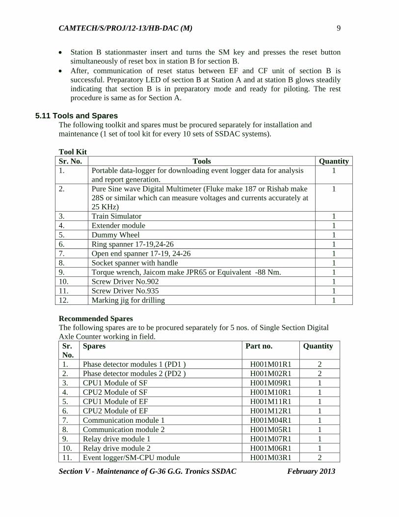
CAMTECH/S/PROJ/12-13/HB-DAC (M)
Section V - Maintenance of G-36 G.G. Tronics SSDAC February 2013
9
Station B stationmaster insert and turns the SM key and presses the reset button simultaneously of reset box in station B for section B.
After, communication of reset status between EF and CF unit of section B is successful. Preparatory LED of section B at Station A and at station B glows steadily indicating that section B is in preparatory mode and ready for piloting. The rest procedure is same as for Section A.
5.11 Tools and Spares
The following toolkit and spares must be procured separately for installation and maintenance (1 set of tool kit for every 10 sets of SSDAC systems). Tool Kit Sr. No. Tools Quantity1. Portable data-logger for downloading event logger data for analysis
and report generation. 1
2. Pure Sine wave Digital Multimeter (Fluke make 187 or Rishab make 28S or similar which can measure voltages and currents accurately at 25 KHz)
1
3. Train Simulator 1 4. Extender module 1 5. Dummy Wheel 1 6. Ring spanner 17-19,24-26 1 7. Open end spanner 17-19, 24-26 1 8. Socket spanner with handle 1 9. Torque wrench, Jaicom make JPR65 or Equivalent -88 Nm. 1 10. Screw Driver No.902 1 11. Screw Driver No.935 1 12. Marking jig for drilling 1 Recommended Spares The following spares are to be procured separately for 5 nos. of Single Section Digital Axle Counter working in field. Sr. No.
Spares Part no. Quantity
1. Phase detector modules 1 (PD1 ) H001M01R1 2 2. Phase detector modules 2 (PD2 ) H001M02R1 2 3. CPU1 Module of SF H001M09R1 1 4. CPU2 Module of SF H001M10R1 1 5. CPU1 Module of EF H001M11R1 1 6. CPU2 Module of EF H001M12R1 1 7. Communication module 1 H001M04R1 1 8. Communication module 2 H001M05R1 1 9. Relay drive module 1 H001M07R1 1 10. Relay drive module 2 H001M06R1 1 11. Event logger/SM-CPU module H001M03R1 2
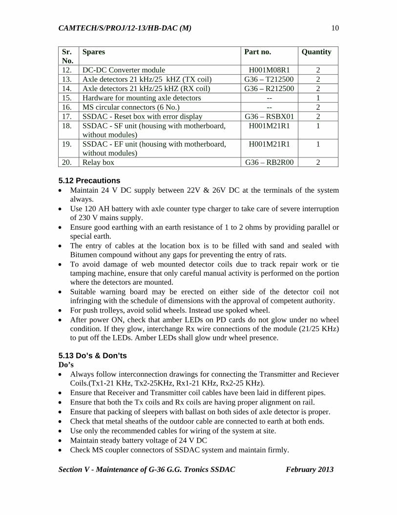
CAMTECH/S/PROJ/12-13/HB-DAC (M)
Section V - Maintenance of G-36 G.G. Tronics SSDAC February 2013
10
Sr. No.
Spares Part no. Quantity
12. DC-DC Converter module H001M08R1 2 13. Axle detectors 21 kHz/25 kHZ (TX coil) G36 – T212500 2 14. Axle detectors 21 kHz/25 kHZ (RX coil) G36 – R212500 2 15. Hardware for mounting axle detectors -- 1 16. MS circular connectors (6 No.) -- 2 17. SSDAC - Reset box with error display G36 – RSBX01 2 18. SSDAC - SF unit (housing with motherboard,
without modules) H001M21R1 1
19. SSDAC - EF unit (housing with motherboard, without modules)
H001M21R1 1
20. Relay box G36 – RB2R00 2 5.12 Precautions Maintain 24 V DC supply between 22V & 26V DC at the terminals of the system
always. Use 120 AH battery with axle counter type charger to take care of severe interruption
of 230 V mains supply. Ensure good earthing with an earth resistance of 1 to 2 ohms by providing parallel or
special earth. The entry of cables at the location box is to be filled with sand and sealed with
Bitumen compound without any gaps for preventing the entry of rats. To avoid damage of web mounted detector coils due to track repair work or tie
tamping machine, ensure that only careful manual activity is performed on the portion where the detectors are mounted.
Suitable warning board may be erected on either side of the detector coil not infringing with the schedule of dimensions with the approval of competent authority.
For push trolleys, avoid solid wheels. Instead use spoked wheel. After power ON, check that amber LEDs on PD cards do not glow under no wheel
condition. If they glow, interchange Rx wire connections of the module (21/25 KHz) to put off the LEDs. Amber LEDs shall glow undr wheel presence.
5.13 Do’s & Don’ts Do’s Always follow interconnection drawings for connecting the Transmitter and Reciever
Coils.(Tx1-21 KHz, Tx2-25KHz, Rx1-21 KHz, Rx2-25 KHz). Ensure that Receiver and Transmitter coil cables have been laid in different pipes. Ensure that both the Tx coils and Rx coils are having proper alignment on rail. Ensure that packing of sleepers with ballast on both sides of axle detector is proper. Check that metal sheaths of the outdoor cable are connected to earth at both ends. Use only the recommended cables for wiring of the system at site. Maintain steady battery voltage of 24 V DC Check MS coupler connectors of SSDAC system and maintain firmly.
CAMTECH/S/PROJ/12-13/HB-DAC (M)
Section V - Maintenance of G-36 G.G. Tronics SSDAC February 2013
11
Preparatory Resetting should be done only after ensuring that there is no train in the section.
It is recommended that heat resisting paint to be used on the apparatus case so that the temperature inside apparatus case is maintained lower in comparison to normal paints.
Place Caution Board near the SSDAC Axle Detectors to avoid damage to the coils from packing machines.
Provide Deflector plates near the SSDAC Axle Detectors to avoid damage to the coils from hanging parts of trains.
Use spoked wheels for push trolleys in place of solid wheels to avoid error in SSDAC system.
Don’ts Do not connect the cable connections loosely. Don’t cut or join the Transmitter/Receiver cables supplied along with the coil. It
would result in change of input Receiver signal. Don’t remove the modules from SSDAC system under Power ON condition. Remove
the modules if necessary after switching OFF the power to the SSDAC system. Local address of CPU-1, CPU-2 and configuration settings of the SSDAC system
should not be changed at the field. When section is in Occupied/Preparatory mode, Motor trolley wheel, Push trolley
with solid mass wheel and Material trolley wheel must not be allowed to Enter/Exit the section to avoid SSDAC system going to Error condition.

CAMTECH/S/PROJ/12-13/HB-DAC (M)
Section V - Maintenance of G-36 G.G. Tronics SSDAC February 2013
12
5.14 Maintenance Log Sheet for SSDAC – G36 Block Section : …………………………….. Station…………………….. SF/EF
S. No.
Date Battery AC Volts Phase Detector 1 Phase Detector 2 With push trolley on Axle Detector (4 spokes)
DC-DC Converters (DC Volts)
TX1 V rms /freq
TX2 V rms /freq
RX1 V rms /freq
RX2 V rms /freq
RX Sig & GND AC Volts
SUP level & GND DC volts
RX PH-SIG & GND socket DC volts
RX Sig & GND AC volts
SUP level & GND DC volts
RX PH-SIG & GND socket DC volts
RX PH – SIG & GND socket
5 V +12 V
-12 V
+18V 24V
Normal Dummy Wheel
Normal Dummy wheel
PD1 PD2 Monitor sockets on DC-DC Converter card FTB
1&2 FTB 52 & 53
FTB 56 & 57
FTB 54& 55
FTB 58& 59
22-30V
40-70 V 20.802 to 21.302 kHz
40-70 V 24.750 to 25.250 kHz
300 mV to 1.2 V
300 mV to 1.2 V
10 to 12 V
< 1 v 10 to 12 V
< 1 v 10 to 12 V
10 to 12 V
4.75 to 5.25 V
11.75 to 12.25 V
-11.75 to -12.25 V
17.75 to 18.25 V
22 to 26 V
CAMTECH/S/PROJ/12-13/HB-DAC (M)
Maintenance of Digital Axle Counters ANNEXURE I - Abbreviations February 2013
ANNEXURE I ABBREVIATIONS Section I :Az LS Eldyne SSDAC AC Alternating Current AzLM Thales Multi Section Digital Axle Counter AzLS Thales Single Section Digital Axle Counter DC Direct Current DIP Dual in line Packeged DP Detection Point EAK Tack side Electronic Unit ETU001 Test equipment (Tool Kit) Hz Hertz LED Light Emitting Diode MESSAB1 Rx voltage for SK1 MESSAB2 Rx voltage for SK2 PCB Printed circuit Board PEGUE1 Reference voltage for SK1 PEGUE2 Reference voltage for SK2 RMS Root Mean Square Rx Reciever Sk1, Sk2 Tx /Rx coil sets SK30H Rail contacts Tx Transmitter Zp30CA-2. Detection points Section II: Az LM Eldyne MSDAC AC Alternating Current ACE Axle Counter Evaluator AzLM Thales Multi Section Digital Axle Counter AzLS Thales Single Section Digital Axle Counter DC Direct Current DIP Dual in line Packeged DP Detection Point EAK Tack side Electronic Unit ETU001 Test equipment (Tool Kit) Hz Hertz ISDN Integrated Services Digital Network LED Light Emitting Diode MESSAB1 Rx voltage for SK1 MESSAB2 Rx voltage for SK2 PCB Printed circuit Board PEGUE1 Reference voltage for SK1 PEGUE2 Reference voltage for SK2 RMS Root Mean Square Rx Reciever Sk1, Sk2 Tx /Rx coil sets SK30H Rail contacts Tx Transmitter Zp30CA-2. Detection points

CAMTECH/S/PROJ/12-13/HB-DAC (M)
Maintenance of Digital Axle Counters ANNEXURE I - Abbreviations February 2013
Section III: Az S 350 U Siemens MSDAC AC Alternating Current AFTC Audio Frequency Track Circuit AWS Automatic Warning System AzGrH Auxiliary Axle Count Reset Button AzGrT Axle Count Reset Button Az S 350 U Siemens Multi Section Digital Axle Counter BLEA Block Input/Output CH Channel DC Direct Current DIN Standards setting organization for Germany kHz Kilo-Hertz LED Light Emitting Diode mV Milli Volt PC Personal Computer RR Reset Restriction SIRIUS Serial computer interface universal board SOPP Internal Software Test STEU Control& Diagnostic TVDS Track Vacancy Detection Section VAU Processing & Monitoring vAzGrT Preparatory Axle Count Reset Button VESBA Amplifier, trigger and band-pass filter WDE Wheel Detection Equipment ZP 43 Wheel detection equipment Section IV: DACF 710 A & DACF 710 P CEL SSDAC AC Alternating Current BPAC Block Proving by Axle Counter CD Carrier Detection CEL Central Electronic Ltd. DACF 710 A Amplitude Modulation type Digital Axle Counter DACF 710 P Phase Reversal type Digital Axle Counter dB Decibel DC Direct Current DIP Dual In line Packaged DNLD Download LCD Liquid Crystal Display LD Level Detector LED Light Emitting Diode LV Last Vehicle MLB Micro Controller Logic Block PR Preparatory Reset Relay PPR Preparatory Proving Relay RDSO Research Designs & Standards Organisation Rx Reciever SCC Signal Conditioning Card SM Station Master SSDAC Single Section Digital Axle CounterTP Trolley Protection Tx Transmitter

CAMTECH/S/PROJ/12-13/HB-DAC (M)
Maintenance of Digital Axle Counters ANNEXURE I - Abbreviations February 2013
VR Vital Relay Section V: G36 G.G. Tronics SSDAC AH Ampere Hour CF Centre Fed CPU Central Processing Unit CFVR Vital Relay for Centre Fed DC Direct Current 2DP1S Two detection points Single section 3DP1S Three detection points Single section 3DP2S Three-detection points for two consecutive sections in a straight line EF End Fed EFVR Vital Relay for End Fed FSK Frequency Shift Keying FTB Fused Terminal Blocks GND Ground Hz Hertz KHz Kilo Hertz LCD Liquid Crystal Diode LDU Lightning Detector Unit LED Light Emitting Diode MS Mild Steel PD Phase Detector PPR Repeater relay for Preparatory Relay PR Preparatory Relay QNA1 Style Q AC immunized relay RDSO Research Design & Standards Organisation Rx Receiver SF Start Fed SFVR Vital Relay for Start Fed SM Station master SSDAC Single Section Digital Axle Counter Tx Transmitter VPR Repeater relay for Vital Relay VR Vital Relay
CAMTECH/S/PROJ/12-13/HB-DAC
Maintenance of Digital Axle Counters ANNEXURE II - References February 2013
ANNEXURE II REFERENCES RDSO Specification No. RDSO/SPN/177/2003 Version 1.0 with amdt.2 RDSO Specification No. RDSO/SPN/177/2003 Version 1.0 with amdt.2 RDSO Specification No.RDSO/SPN/177/2012 Version 3.0 RDSO specification No.RDSO/ SPN /176 /2005 Version 2.0 AzLS installation guideline – M/s Eldyne Electro-Systems Pvt. Ltd. AzLM installation guideline – M/s Eldyne Electro-Systems Pvt. Ltd. Installation Manuals - Single section Digital Axle Counter DACF -710 A & DACF 710 P – M/s Central Electronics Ltd. SSDAC G-36 2DP1S Operation and Maintenance Manual (SSDAC-2DP1S-MM)
Version 1.0– M/s G.G.Tronics India Pvt.Ltd. Maintenance Instructions Az S 350 U Microcomputer Axle Counting System – M/s
Siemens Ltd. Installation and Maintenance Instructions DEK 43 Electronic Double Wheel
Detector for ZP 43 Wheel Detection Equipment – M/s Siemens Ltd. Operating & Service Manual ZP43 (S210) Wheel Detection Equipment