digital axle counter - indian railway · section i.e there is only one entry point and one exit...
TRANSCRIPT

Hkkjr ljdkj &GOVERNMENT OF INDIA jsy ea=ky;& MINISTRY OF RAILWAYS ¼dk;kZy;hu iz;ksx gsrq½& (For official use only)
MAINTENANCE HANDBOOK ON
DIGITAL AXLE COUNTER
(MULTI SECTION)
CAMTECH/2008/S/MSDAC/1.0
DECEMBER 2008
Maharajpur, Gwalior – 474 005
Tele: 0751-2470185, Fax:0751-2470841, e-mail: [email protected]
Centre for Advanced Maintenance TECHnology Excellence in Maintenance
MAINTENANCE HANDBOOK ON
DIGITAL AXLE COUNTER (MULTI SECTION)
CAMTECH/2008/S/MSDAC/1.0 December 2008
PART- A
DIGITAL AXLE COUNTER (MULTI SECTION)
No. of pages - 6
PART-B
Az LM ELDYNE MULTI SECTION DIGITAL AXLE COUNTER
No. of pages - 24
PART – C
AzS350 U SIEMENS MULTI SECTION DIGITAL AXLE COUNTER
No. of pages - 27

FOREWORD
Track circuit and axle counter play a vital role in Railway Signalling and their
failure affects the punctuality of trains. Digital Axle counter is the latest
modification in this field to provide enhanced reliability.
CAMTECH is continuously putting efforts in documentation and upgradation of
information on maintenance practices. The current handbook has been
developed on Multi Section version of Digital Axle Counter which is being
installed at various Railway stations/yards on Indian Railways.
It gives me great pleasure in presenting this handbook to the Signal maintenance
personnel and I hope that it will prove useful to them in maintaining the above
system. All the concerned field personnel should in their own interest get
acquainted with the information given in this handbook, for efficient working of
the system installed in their sections.
CAMTECH GWALIOR S.C. SINGHAL Date: 24.12.2008 EXECUTIVE DIRECTOR

PREFACE
Axle Counters initially developed using transistorized circuits and ICs have their
own limitations and frequent failures due to trolley suppression track circuits. To
overcome these problems the micro-controller and softwares based Digital Axle
Counters were developed, which proved to be more reliable with inherent safety
features. This handbook has been prepared to help the field maintenance
personnel to provide trouble-free working of Multi section Digital Axle Counter
system which is progressively being installed on Indian Railways.
It is clarified that this handbook does not supersede any existing provisions laid
down in the Signal Engineering Manual, Railway Board publications and Zonal
Railways instructions. The instructions given in it are for the purpose of guidance
only.
We are sincerely thankful to Shri A.K.Jain, Director/Signal RDSO, Shri Deepak
Arora, Sr. D.S.T.E.(Co) Bhopal,W.CRly., Shri Sunil Kumar, Sr.D.S.T.E.Bhusawal,
C.Rly., M/s Eldyne Electrosystems Pvt. Ltd. Kolkata, M/s Siemens Ltd., Mumbai
and field personnel who helped us in preparing this handbook.
CAMTECH GWALIOR JAGMOHAN RAM Date:19.12.2008 DIRECTOR (S & T)

CONTENTS
PART- A
DIGITAL AXLE COUNTER (MULTI SECTION)
Sr.No. Description Page No.
1. Introduction……………………………………………………….. 1 2. Types of Digital Axle Counter………………………………….. 1 3. Multiple Section Digital Axle Counter………………………….. 1 3.1 General Description……………………………………………... 1 3.2 Communication…………………………………………………… 2 3.3 Salient Features……………………………………………….… 3 3.4 Configuration……………………………………………………… 3 4. Main Parts………………………………………………………… 3 4.1 Functions of various parts………………………………………. 4 4.1.1 Axle detector……………………………………………………… 4 4.1.2 DAC Field unit……………………………………………………. 4 4.1.3 Central Evaluator………………………………………………… 4 4.1.4 Reset module/panel..……………………………………………. 4 4.1.5 Line Verification box……………………………………………... 5 4.1.6 Vital relay drive and Relay unit……………………………….… 5 4.1.7 Event Logger……………………………………………………… 5 4.1.8 Diagnostic terminal………………………………………………. 5 5. Resetting of Digital Axle Counter………………………………. 6 5.1 Preparatory Reset……………………………………………….. 6 5.2 Hard Reset …………………………………………………….… 6 6. RDSO approved firms…………………………………………… 6

CONTENTS
PART-B
Az LM: ELDYNE MULTI SECTION DIGITAL AXLE COUNTER Sr.No. Description Page No.
1. Introduction………………………………………………………. 1 2. Main Modules and their functions……………………………… 1 2.1 Outdoor Trackside system……………………………………… 1 2.1.1 Rail Contact (SK30H)…………………………………………… 2 2.1.2 Track-Side Electronic Unit (EAK)……………………………… 2 2.2 Indoor Equipment……………………………………………….. 2 2.2.1 Axle Counter Central Evaluator (ACE)……………………….. 2 2.3 Communication Link (With or without PDCU).………………. 3 3. Installation ……………………………………………………….. 3 3.1 Installation of Rail Contacts (SK 30H)………………………… 3 3.1.1 Drilling of mounting holes ..…………………………………….. 4 3.1.2 Drilling Jig ………………………………………………………... 4 3.1.3 Mounting of Rail Contact ..……………………………………... 5 3.2 SK30H installation ……………………………………………… 5 3.3 Important instructions to be followed during installation of
Rail Contacts (SK30H)……………………………………….. 6
3.4 Installation of Track-Side Electronic Unit (EAK)……………… 7 3.5 Connections……………………………………………………… 7 3.6 Power Supply……………………………………………………. 9 3.7 Earthing of EAK…………………………………………………. 9 3.8 Installation of Axle Counter Central Evaluator (ACE)……….. 9 3.8.1 Power Supply to ACE ………………………………………….. 9 3.8.2 Connection to the detection point……………………………… 10 3.8.3 Connection of relays……………………………………………. 10 3.8.4 Connection of PDCU……………………………………………. 10 3.8.5 Arrangement of Serial and Parallel cards in ACE……………. 11 4. Adjustment of Rail contact……………………………………… 12 4.1 Adjustment of Tx head with Dummy wheel and Tool Kit…… 12 4.2 Test equipment (Tool Kit) ETU001……………………………. 12 4.2.1 Functions of Test Equipment ETU001………………………... 12 4.2.2 Contents of Test Equipment ETU001………………………… 13 4.2.3 Selector Switch functions………………………………………. 13 4.3 Parameters to be checked for adjustment of rail contact…… 14 4.3.1 Measurement of Channel 1 & 2.………………………………. 14 4.3.2 Measurement of MESSAB1 & MESSAB2.…………………… 14

Sr.No. Description Page No.
4.3.3 Measurement of PEGUE1 & PEGUE2..……………………… 14 4.3.4 Measurement of voltage and frequency of TX heads……….. 14 4.3.5 Measurement of Power Supply Voltage..…………………….. 14 4.4 Adjustment procedure….……………………………………….. 15 4.4.1 Adjustment of MESSAB1……………………………………….. 15 4.4.2 Trolley Suppression……………………………………………... 15 4.4.3 Adjustment of MESSAB2……………………………………….. 16 4.4.4 Adjustment of PEGUE1………………………………………… 16 4.4.5 Adjustment of PEGUE2………………………………………… 16 5. Address setting………………………………………………….. 16 6. Diagnostics……………………………………………………….. 17 6.1 LED indications on EAK………………………………………… 17 6.2 Diagnostics information through LED display of various
boards of ACE…………………………………………………… 18
6.2.1 Power Supply board normal display…………………………... 18 6.2.2 Serial I/O board normal display………………………………... 19 6.2.3 Serial I/O board normal display………………………………... 19 6.2.4 Computer board normal display…………...…………………... 20 6.3 System Diagnostics by computer……………………………… 20 7. Reset Box………………………………………………………… 20 7.1 Steps to initiate a reset…………………………………………. 21
Annexure I - Maintenance Log-sheet for Eldyne MSDAC Annexure II – Technical data - Eldyne MSDAC Annexure III – Abbreviations used in Part B

CONTENTS
PART - C
AzS350 U : SIEMENS MULTI SECTION DIGITAL AXLE COUNTER Sr.No. Description Page No.
1. Introduction ……………………………………………………... 1 1.1 Outdoor Equipment ……………………………………………. 1 1.2 Indoor Equipment………………………………………………. 1 2. Mode of Operation……………………………………………… 2 3. Power Supply……………………………………………………. 2 3.1 Power Supply for indoor equipment………………………….. 2 3.2 Power Supply for outdoor equipment…………………..…….. 2 4. Double Usage of Counting Heads……………………………. 2 4.1 Analogue double usage……………………………………….. 3 4.2 Digital double usage……………………………………………. 3 4.3 Double usage via SIRIUS2 Board…………………………….. 3 5. Installation …………..…………………………………………... 3 5.1 Installation of Outdoor equipments………………………...…. 3 5.1.1 DEK 43 Double Wheel Detector………………………………. 4 5.1.2 Connecting Cables …………………………………………….. 6 5.1.3 Trackside Connection Box…………………………………….. 6 5.1.4 Permissible distances………………………………………….. 9 5.1.5 External Power Supply for ZP 43 (Optional)………………… 9 5.1.6 Double Usage for ZP 43 (Optional)…………………………… 9 5.1.7 Over voltage Protection for ZP 43…………………………….. 9 5.2 Installation of Indoor equipments……………………………... 10 5.2.1 AzS350U Axle counting cabinets…………………………….. 10 6. Overview of Boards……………………………………………. 11 6.1 SIRIUS2 (serial computer interface universal) board………. 11 6.2 BLEA12 boards………………………………………… ……… 11 6.3 STEU control and diagnostic board………………………….. 12 6.4 VAU & CPU board …………………………………………….. 12 6.5 VESBA board…………………………………………………… 12 6.6 DIGIDO Board………………………………………………….. 12 6.7 SVK2150 Power Supply Board……………………………….. 12 7. Reset Options…………………………………………………… 13 7.1 Immediate axle count reset/Hard reset………………………. 13 7.2 Preparatory axle count reset…………………………………... 13 8. Tools required for installation, testing, commissioning and
maintenance…………………………………………………….. 14
9. Adjustment and commissioning ………………………………. 14 9.1 Adjustments to be done at the Outdoor junction Box…….… 14 9.2 Central evaluator adjustments ………………………………... 15

Sr.No. Description Page No.
9.3 Measurement of Parameters …………………………………. 15 10. Maintenance…………………………………………………….. 17 10.1 ZP43 Wheel detection equipment…………………………….. 17 10.2 Diagnostics………………………………………………………. 17 10.2.1 Out door equipment…………………………………………….. 17 10.2.2 Indoor Equipment……………………………………………….. 18 11. Fault finding and troubleshooting……………………………... 20 12. Do’s and Don’ts…………………………………………………. 24 12.1 Do’s………………………………………………………………. 24 12.2 Don’ts…………………………………………………………….. 24
Annexure IV - Maintenance Log-sheet for Siemens MSDAC Annexure V – Technical data - Siemens MSDAC Annexure VI – Abbreviations used in Part C

CAMTECH/S/2008/MSDAC/1.0
Digital Axle Counter (Multi Section) December 2008
1
PART- A
DIGITAL AXLE COUNTER (MULTI SECTION) 1. Introduction
Axle counter is a device for monitoring a specified section of track for the presence of vehicle. Conventional Axle counters were designed with transistorized circuits and ICs. Now Axle Counters are designed using Micro-Controllers and Software program, and these are called as “Digital Axle Counters”. The communication used in the system is by means of packets for exchange of information between units. This communication is in duplex mode and is fail safe. (In duplex mode data is exchanged between two connected devices in both directions simultaneously. Data flow takes place independently in both directions)
2. Types of Digital Axle Counter There are two types in use:
• Single Section Digital Axle Counter • Multiple Section Digital Axle Counter
Single section axle counters are generally used to monitor a single track section i.e there is only one entry point and one exit point for a particular track section. Digital data is transmitted directly between two axle counter field equipments by means of modem communication. Whereas a Multi Section Digital Axle Counter is used to monitor a portion of line called as “Track Section” confined by multiple Entry & Exit points. There are counting heads (Axle Detectors) at the beginning and end of each track section. These units are connected to an evaluation computer (Central Evaluator) which processes the information generated by the counting heads. If the number of axles counted in matches that counted out, the respective track section is indicated as being clear.
3. Multiple Section Digital Axle Counter 3.1 General Description
Multi Section Digital Axle Counter consists of axle detectors and field units configuring upto (n-1) track sections, where n is the number of detection points. It is capable of counting axles, count comparison, finding direction of axle movement, supervision, relay drive and transmission of counts and health of axle detectors and field units. The field units are connected to the Central Evaluator by transmission medium where transmission is in VF range. Track clear indication shall only be given when IN count and OUT count are equal and equipment is functioning all right. Axle counter shows
CAMTECH/S/2008/MSDAC/1.0
Digital Axle Counter (Multi Section) December 2008
2
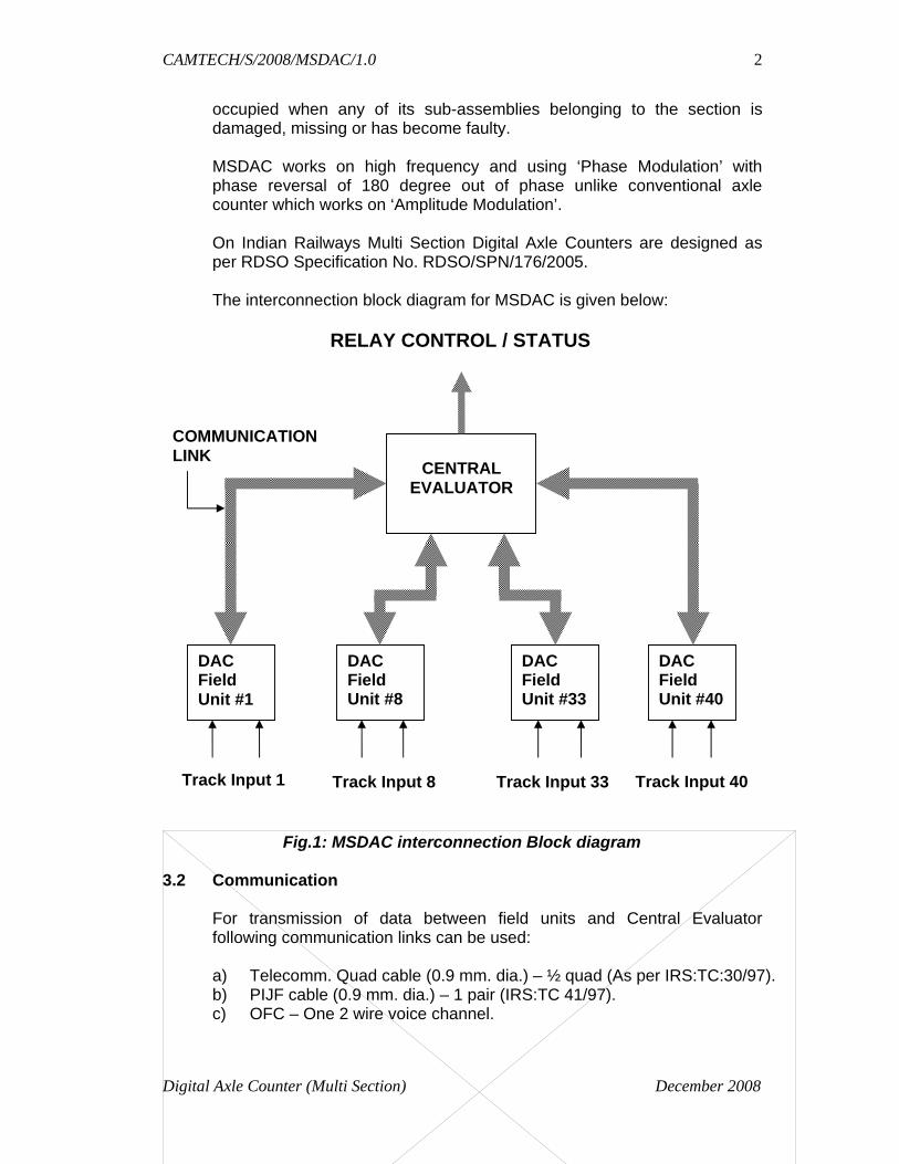
occupied when any of its sub-assemblies belonging to the section is damaged, missing or has become faulty. MSDAC works on high frequency and using ‘Phase Modulation’ with phase reversal of 180 degree out of phase unlike conventional axle counter which works on ‘Amplitude Modulation’.
On Indian Railways Multi Section Digital Axle Counters are designed as per RDSO Specification No. RDSO/SPN/176/2005.
The interconnection block diagram for MSDAC is given below:
Fig.1: MSDAC interconnection Block diagram 3.2 Communication
For transmission of data between field units and Central Evaluator following communication links can be used:
a) Telecomm. Quad cable (0.9 mm. dia.) – ½ quad (As per IRS:TC:30/97). b) PIJF cable (0.9 mm. dia.) – 1 pair (IRS:TC 41/97). c) OFC – One 2 wire voice channel.
CENTRAL
EVALUATOR
DAC Field Unit #1
DAC Field Unit #8
DAC Field Unit #33
DAC Field Unit #40
RELAY CONTROL / STATUS
Track Input 1 Track Input 8 Track Input 33
COMMUNICATION LINK
Track Input 40
CAMTECH/S/2008/MSDAC/1.0
Digital Axle Counter (Multi Section) December 2008
3
3.3 Salient Features • The Central Evaluator is connected to DAC field units in Star configuration. • Each track section can be reset independently from the Reset box/Reset
module of Reset panel with co-operation of line verification box simultaneously.
• The Event logger records all the events occurring in the multiple section digital axle counter with RTC.
• It has such an arrangement that wheels of push trolleys with 4 spokes or 6 spokes are not counted. Dip lorries, rail dollies etc. are not counted by it but they disturb the axle counter and it shows failed indication. Trolley protection track circuit is not required with phase modulation.
3.4 Configuration
Multi Section Digital Axle Counter can be easily configurable as per yard layout in different track sections as given below:
1. One detection point single section : In terminal lines/siding. 2. Two detection points single section: In straight line. 3. Three detection points single section: In point zone. 4. Four detection points single section: In point zone. 5. Multiple detection points single section: In ladder. 6. Consecutive single section in a straight line.
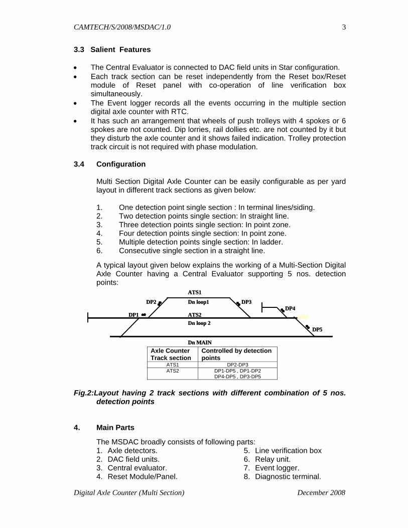
A typical layout given below explains the working of a Multi-Section Digital Axle Counter having a Central Evaluator supporting 5 nos. detection points:
ATS1
DP2 Dn loop1 DP3 DP4
DP1 ATS2 Dn loop 2
DP5
Dn MAIN
ATS1
DP2 Dn loop1 DP3 DP4
DP1 ATS2 Dn loop 2
DP5
Dn MAIN Axle Counter Track section
Controlled by detection points
ATS1 DP2-DP3 ATS2 DP1-DP5 , DP1-DP2
DP4-DP5 , DP3-DP5
Fig.2:Layout having 2 track sections with different combination of 5 nos.
detection points 4. Main Parts
The MSDAC broadly consists of following parts: 1. Axle detectors. 2. DAC field units. 3. Central evaluator. 4. Reset Module/Panel.
5. Line verification box 6. Relay unit. 7. Event logger. 8. Diagnostic terminal.

CAMTECH/S/2008/MSDAC/1.0
Digital Axle Counter (Multi Section) December 2008
4
4.1 Functions of various parts 4.1.1 Axle detector
It comprises of two sets of TX/RX coils/sensors. These operate at frequencies above 20 KHz. These are of web mounted type.
4.1.2 DAC Field unit
It has 2 out of 2 architecture. It detects and counts axles passing over the axle detector as well as determine the direction of passing axles . These transmit axle counts and health status to Central Evaluator at regular intervals. Provision is available for setting unique address of each field unit. The address shall be minimum 8 bits.
4.1.3 Central Evaluator
The Central Evaluator is based on 2 out of 3 logic. This is housed in relay hut provided at the station. This is connected to DAC field units in star configuration. The Central Evaluator provides one vital relay output for each track section.
It receives the reset command generated from reset unit for section-wise resetting of track section(s). It provides input to the Event logger for registration and recording of events occurring in the multiple section digital axle counter.
It has an RS-232 port (9600 bits/sec) to interface with Electronic interlocking system as per RDSO/SPN/148. It has separate port to connect to station data logger as specified in RDSO/SPN/99. It can communicate with DAC field units.
4.1.4 Reset Module/Panel
Reset boxes are provided in ASM room housed in a Reset panel/Reset module to reset respective track sections. These work from 24 V DC supply. The following are provided in the Reset box/Module: 1. A six digit (min.) non-resettable type counter. 2. Reset switch with key. 3. Reset push button – RED. 4. Axle counter section clear indication – GREEN. 5. Axle counter section occupied indication – RED. 6. Power OK indication – YELLOW. 7. Preparatory reset indication – GREEN. 8. Line verification indication –YELLOW.
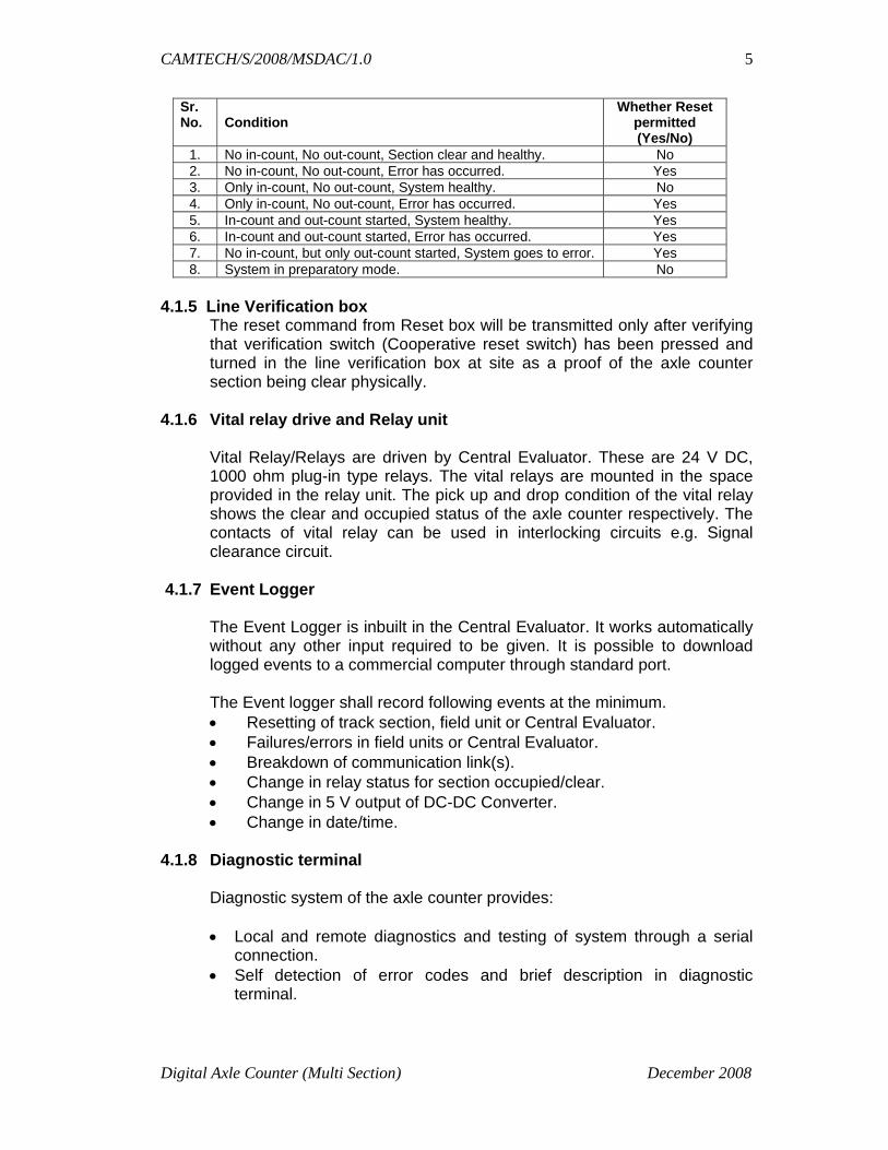
The possibility of reset will be as per table on next page:
CAMTECH/S/2008/MSDAC/1.0
Digital Axle Counter (Multi Section) December 2008
5
Sr. No.
Condition
Whether Reset permitted (Yes/No)
1. No in-count, No out-count, Section clear and healthy. No 2. No in-count, No out-count, Error has occurred. Yes 3. Only in-count, No out-count, System healthy. No 4. Only in-count, No out-count, Error has occurred. Yes 5. In-count and out-count started, System healthy. Yes 6. In-count and out-count started, Error has occurred. Yes 7. No in-count, but only out-count started, System goes to error. Yes 8. System in preparatory mode. No
4.1.5 Line Verification box
The reset command from Reset box will be transmitted only after verifying that verification switch (Cooperative reset switch) has been pressed and turned in the line verification box at site as a proof of the axle counter section being clear physically.
4.1.6 Vital relay drive and Relay unit
Vital Relay/Relays are driven by Central Evaluator. These are 24 V DC, 1000 ohm plug-in type relays. The vital relays are mounted in the space provided in the relay unit. The pick up and drop condition of the vital relay shows the clear and occupied status of the axle counter respectively. The contacts of vital relay can be used in interlocking circuits e.g. Signal clearance circuit.
4.1.7 Event Logger
The Event Logger is inbuilt in the Central Evaluator. It works automatically without any other input required to be given. It is possible to download logged events to a commercial computer through standard port.
The Event logger shall record following events at the minimum. • Resetting of track section, field unit or Central Evaluator. • Failures/errors in field units or Central Evaluator. • Breakdown of communication link(s). • Change in relay status for section occupied/clear. • Change in 5 V output of DC-DC Converter. • Change in date/time.
4.1.8 Diagnostic terminal
Diagnostic system of the axle counter provides: • Local and remote diagnostics and testing of system through a serial
connection. • Self detection of error codes and brief description in diagnostic
terminal.

CAMTECH/S/2008/MSDAC/1.0
Digital Axle Counter (Multi Section) December 2008
6
• The same display normally shows in count/out count detection point-wise and section-wise and software version No. when the system is switched on initially.
• After running the diagnostic software, the system data (viz. Current data and Historical data) can be downloaded and analysed on the PC. The historical data may be used to reconstruct the sequential occurrence of events happened in the system.
5. Resetting of Digital Axle Counter
There are two types of resetting done for a Multi Section Digital Axle Counter:
i) Preparatory Reset ii) Hard Reset
5.1 Preparatory Reset
For track section on a straight line confined by two detection points, when reset is applied, the axle counter section goes to “Preparatory Reset Mode”. The preparatory reset LED in Reset box/Reset module of reset panel glows and reset counter increments. The axle counter section will still be in ‘occupied state’. It becomes clear only after more than one in-count from one end and same number of out-count from the other end takes place.
5.2 Hard Reset
For track section on a terminating line/siding line, point zone and ladder, the reset command from Reset box/Reset Module of Reset panel will be transmitted only after verifying that verification switch (Cooperative reset) has been pressed and turned in the line verification box at site as a proof of the axle counter section being clear physically. On availability of reset command, the section resets instantly and show clear and the counter increments. Note: (a) A reset operation is only possible when section is occupied or
disturbed or there is an error in the system . (b) Reset key operation (including line verification switch) should be
performed by an authorized person only. 6. RDSO approved firms
At present there are two RDSO approved firms for supply and installation of Multi Section Digital Axle Counter on Indian Railways: 1. M/s Eldyne Electrosystems Pvt. Ltd., Kolkata. 2. M/s Siemens India Ltd., Navi Mumbai. Part B and Part C of this handbook cover axle counters of above firms respectively.

CAMTECH/S/2008/MSDAC/1.0
AzLM – Eldyne Multi Section Digital Axle Counter December 2008
1
PART-B
Az LM ELDYNE MULTI SECTION DIGITAL AXLE COUNTER
1. Introduction
This part provides brief description and specific guidelines for installation, commissioning, adjustment and maintenance of Multi Section Digital Axle Counter of AzLM system manufactured by M/s Eldyne Electro-systems Pvt. Ltd., in association withThales of Germany.
2. Main Modules and their functions
AzLM system consists of following main modules:
• Outdoor Trackside system: Rail contacts (SK30H) & Track-Side Electronic Unit (EAK) (ZP30H)
• Indoor Equipment: Axle Counter Central Evaluator (ACE) • Communication Link (With or without PDCU)
2.1 Outdoor Trackside system 2.1.1 Rail Contact (SK30H)
It consists of Transmitter, Receiver, Protective hose and fixing parts for hose. The rail contact Sk30H is connected to the to the Track side Electronic unit (EAK). It consists of two coil sets, Sk1 and Sk2, both installed on the same rail. When a wheel passes, these supply two time-offset signals which are fed to
EAK which processes these signals and produces IN counts and OUT counts. These In/Out counts are fed to the Axle Counter Central Evaluator (ACE) through communication link for further processing.
Receiving heads
Transmitter heads
Protective hose
Cable to EAK
Sleeper
Rail
Fig.2.1: Rail Contacts (SK30H)

CAMTECH/S/2008/MSDAC/1.0
AzLM – Eldyne Multi Section Digital Axle Counter December 2008
2
2.1.2 Track-Side Electronic Unit (EAK) Track-Side Electronic Unit (EAK) is installed near Rail Contacts SK30H and connected to it via integral cables. Electronic Unit EAK consists of Analog Card, Digital Card , Motherboard and spare slot for additional PCB (Digital Card) and housing. It detects and counts axles passing over the Rail Contacts as well as determine the direction of passing axles. These transmit axle counts and health status to Central Evaluator at regular intervals. Each EAK connected to the same ACE has a unique address. 2.2 Indoor Equipment 2.2.1 Axle Counter Central Evaluator (ACE)
Axle Counter Central Evaluator is the decision making unit for multi section digital axle counter. It has the following sub parts which are housed in a Sub-rack. CPU Card CPU Card acts as the brain of AzLM which have diagnostic interfaces and an alphanumeric display. Two CPU Cards are required for 2 out of 2 system.
1 2 3 41 2 3 4
Evaluator/ Digital Board Analog Board Sub Rack WAGO terminals Ground plate Cable to 1. Transmitter 1 2. Receiver 1 3. Receiver 2 4. transmitter 2 Housing Base
Fig.2.2: Track-Side Electronic Unit (EAK)
1 2 1 2 3 4
4
5 5 3
1 Power supply
5 Parallel I/O
3 Covering plate
4 Serial I/O
2 Computer CPU card
5
4
4 4 5
3
1 2 1 2 3 4
4
5 5 3
5
4
4 4 5
3 Fig.2.3: a) Front view of Axle Counter Evaluator b) Complete Evaluator cabinet

CAMTECH/S/2008/MSDAC/1.0
AzLM – Eldyne Multi Section Digital Axle Counter December 2008
3
Power Supply Card It has DC-DC converters. It works on 24 V DC and generates 5 V DC and 12 V DC required for the electronic circuitry. Two Power Supply Cards are required for 2 out of 2 system.
Serial Card It receives information from detection points through ISDN communication link and provides this information to CPU Cards. One Serial Card can monitor maximum two detection points.
Parallel Card It is responsible for providing section information. One parallel card can monitor maximum one section only.
2.3 Communication Link (With or without PDCU)
The system uses two wire ANSI T1.601 communication protocol with ISDN modulation for communication between ACE and EAK. For better reliability the correct pair of star quad cable should be used with proper terminations as shown in Fig.2.4 below:
Maximum distance communication link possible is 13 Km when attenuation of the link is 24 dB. For using same conductor for power and data, Power Data Coupling Unit (PDCU) is used.
3. Installation Installation must be carried out in accordance with RDSO approved pre-
commissioning checklist for the equipment. 3.1 Installation of Rail Contacts (SK 30H)
• Selection of location for installing Rail Contact on the rail web between two sleepers as per approved signalling plan.
• Any embossments on the rail web must be removed else another location for the rail contact has to be selected.
Figure 2.4: Matched Pair of 4 Quad Cable
QUAD 1: 1st Pair: Blue - White & 2nd Pair Red – Grey. QUAD 2: 5th Pair: Brown - White & 2nd Pair Red – Grey. QUAD 3: 3rd Pair: Green - White & 2nd Pair Red – Grey. QUAD 4: 7th Pair: Orange - White & 2nd Pair Red – Grey

CAMTECH/S/2008/MSDAC/1.0
AzLM – Eldyne Multi Section Digital Axle Counter December 2008
4
• On double line section the rail contact should be mounted preferably on the outside rail.
• Recommended distance from rail joint (fish-plated or welded or insulating joint)
- not less than 1 metre, in normal conditions. - not less than 2 metre, if the condition of the track is poor.
• Mandatory distance from rail contact of same type (Sk30, Sk30H) of a neighbouring detection
- not less than 2 metre. 3.1.1 Drilling of Mounting Holes
Drill the mounting holes on the rail web in correct position as per following approximation formula:
a = (0.409 * h), where a = height of the mounting hole h = height of the rail
Note: (i) All the heights are to be measured from the foot of the rail. (ii) This formula is only a general one for an initial guideline. For more accuracy, guidance from a pilot installation should be taken.
Figure 2.5: Drilling Position for installation of Rail Contacts
a1 or a2 or a3 = a-calculated+1.5 mm. b = 13 mm+0.2 mm c = 148 mm+0.2 mm
Height of mounting hole for different rail profiles is given below:
Rail Profile 90 lb 52 Kg 60 Kg a [mm] 56 mm 63 mm 68 mm
Drill the final three holes of diameter 13mm on the rail web with the help of drilling jig.
3.1.2 Drilling Jig The drilling jig consists of:
i) Drilling template
CAMTECH/S/2008/MSDAC/1.0
AzLM – Eldyne Multi Section Digital Axle Counter December 2008
5
ii) Mounting device for the drilling machine iii) Templates for the standard rail profiles iv) Fastening device v) The drilling machine
3.1.3 Mounting of Rail Contact
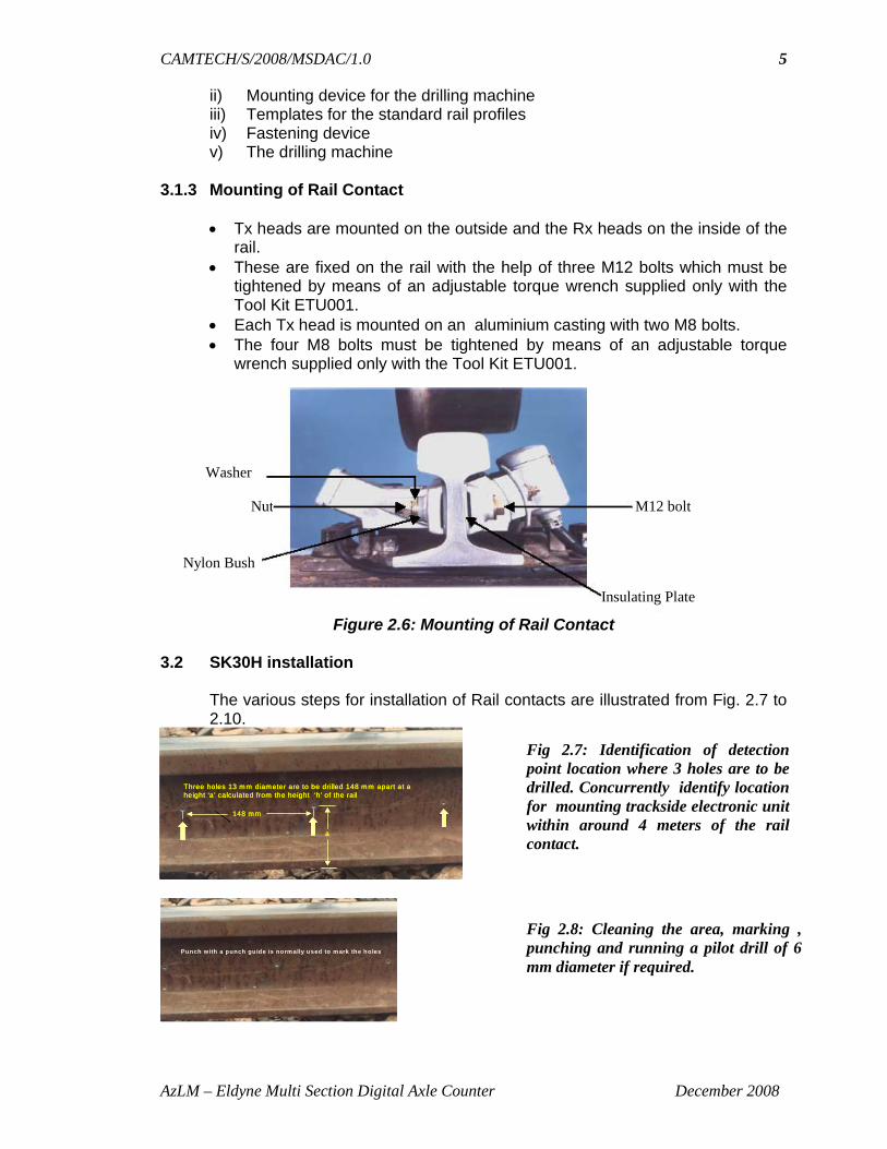
• Tx heads are mounted on the outside and the Rx heads on the inside of the rail.
• These are fixed on the rail with the help of three M12 bolts which must be tightened by means of an adjustable torque wrench supplied only with the Tool Kit ETU001.
• Each Tx head is mounted on an aluminium casting with two M8 bolts. • The four M8 bolts must be tightened by means of an adjustable torque
wrench supplied only with the Tool Kit ETU001.
Washer
Nut
Nylon Bush
Insulating Plate
M12 bolt
Figure 2.6: Mounting of Rail Contact
3.2 SK30H installation
The various steps for installation of Rail contacts are illustrated from Fig. 2.7 to 2.10.
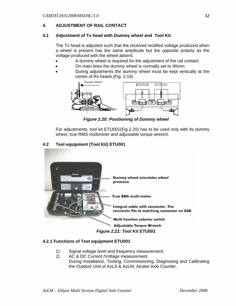
Three holes 13 mm diameter are to be drilled 148 mm apart at a height ‘a’ calculated from the height ‘h’ of the rail
148 mm
a
Three holes 13 mm diameter are to be drilled 148 mm apart at a height ‘a’ calculated from the height ‘h’ of the rail
148 mm
a
Three holes 13 mm diameter are to be drilled 148 mm apart at a height ‘a’ calculated from the height ‘h’ of the rail
148 mm
a
Punch w ith a punch guide is norm ally used to m ark the holes
Fig 2.7: Identification of detection point location where 3 holes are to be drilled. Concurrently identify location for mounting trackside electronic unit within around 4 meters of the rail contact.
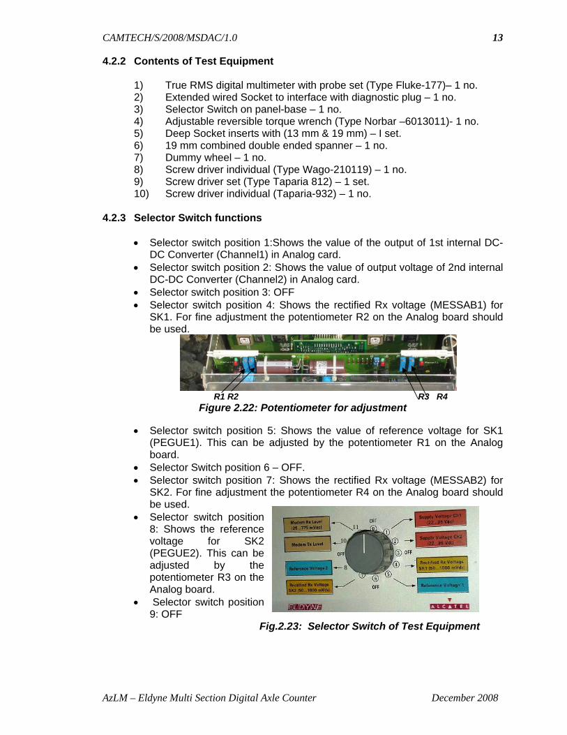
Fig 2.8: Cleaning the area, marking , punching and running a pilot drill of 6 mm diameter if required.

CAMTECH/S/2008/MSDAC/1.0
AzLM – Eldyne Multi Section Digital Axle Counter December 2008
6
3.3 Important instructions to be followed during installation of Rail Contacts
(SK30H) • The teeth and grooves of aluminium casting and the Tx head should be
correctly lined-up. • After tightening the nuts, the bolts should protrude a minimum of 2mm.. • The transmitter head must not touch the rail-head. • The brackets for the protective hose must be insulated from the rail. By
inserting nylon bushes into the holes of the bracket. • Mark the rail contact integral cables, before putting them inside the
protective hose, as Sk1 / Sk2 according to reference count direction so that correct cables can be identified after taking out at the other end.
• The protective hose must be cut to the correct length before the cable is inserted. The hose must be made watertight with a rubber seal on the rail contact side and the hose clamp on the side of the EAK.
• Exposed integral cables at the Tx & Rx side should have adequate radius of curvature to avoid stress and contact with the ballast.
• The integral cables of rail contacts must be laid directly from the track to the electronic unit avoiding loops/coils. The integral cables are available in three different lengths 4m, 5.5m and 8m. Right length of integral cable should be chosen before installation. The cable should not be shortened.
• Deflector plates to be installed as shown in figure 2.11 to protect the rail contacts from hanging metal objects from passing train
Fig 2.9: Three 13 mm holes are drilled accurately.
Fig 2.10: Cleaning and deburring the drilled hole
Fitting of Tx heads on the outside and Rx heads on the inside of the rail Protecting tube should be mounted on brackets with integral cable as per specified bends
and clamping.(Refer Fig.2.1)

CAMTECH/S/2008/MSDAC/1.0
AzLM – Eldyne Multi Section Digital Axle Counter December 2008
7
. 3.4 Installation of Track-Side Electronic Unit (EAK)
EAK, if installed, out side the location box should be installed in the Lockable Mushroom Cover with SS stand (EPC 001–CI Eldyne make). If EAK is placed inside the location box it is recommended to house the EAK with a dust cover (Eldyne make).
3.5 Connections
The rail contacts are connected according to table below.
Rail contact and wire colour Terminal on Zp30H(EAK) Rx 1(black) Sk1 / E1 Rx 1 (transparent) Sk1 / E2 Rx 1 (blue) Sk1 / E3 Tx 1 (transparent) Sk1 / S2 Tx 1 (black) Sk1 / S1 Tx 2 (black) Sk2 / S1 Tx 2 (transparent) Sk2 / S2 Rx 2 (blue) Sk2 / E3 Rx 2 (transparent) Sk2 / E2 Rx 2 (black) Sk2 / E1
Figure 2.11: Installation of Deflector Plates
Fig. 2.12 (a) Mushroom cover with pedestal (b) EAK installation

CAMTECH/S/2008/MSDAC/1.0
AzLM – Eldyne Multi Section Digital Axle Counter December 2008
8
• Connect the screen of the rail contact cables to the earthing bar • Remove the cable insulation for a length of approximately 45mm. • Fasten the screen to the earthing bar by means of a cable tie and
connect the screen to the earthing bar using the clip supplied. • The pairs of wire have to be twisted properly as shown in Fig. 2.13.
Twisting conductors Exposing the screen Earthing clip
Fig. 2.13: Fixing of Rail Contact Integral Cable at EAK Side Following table shows the connection for Power Supply / Communication to the EAK :
Connections Terminals Superimposed Power (+) & Data Line 3 Superimposed Power (-) & Data Line 13
Provide a shorting link between terminal 2 & 1 and 12 & 11 if the same pair of conductors is used for superimposed data and power supply to the EAK. If separate power supply is used for installation, the communication line has to be between terminals 3 & 13 and the 60V power supply has to be connected to terminals 1 & 11.
Fig. 2.14: Termination of
EAK
bk
b1
bk
bk
bk
b1
717
19
20
18
9
10
8 tr
( -
) Po
wer
Sup
ply
( +
) P
ower
Sup
ply
1516 6
5
14
1312
4
32
EAK 30 H tr
tr
tr
11 1
E3
SK1
E1
E2
Rx Tx
E1
S2
S1
SK2S1
S2
E3E2
Rx Tx

CAMTECH/S/2008/MSDAC/1.0
AzLM – Eldyne Multi Section Digital Axle Counter December 2008
9
3.6 Power Supply
• Recommended power supply for EAK for AzLM is 54 VDC to 72 VDC. • Power consumption per EAK - 9W (approx.). • Recommended ripple content of the power supply <24mV peak to peak.
3.7 Earthing of EAK
The EAK has to be connected to the earth with a copper cable of minimum 25mm2 or an iron cable of minimum 50mm2. The housing has to be earthed to a suitable low inductance (approximately L<40µH) and low resistance (approximately R<4 ohm) earth.
Fig.2.15 : Earth Connection 3.8 Installation of Axle Counter Central Evaluator (ACE) ACE is installed in a relay hut near station. The following connections are to be made during installation of ACE.
• Power Supply to ACE. • Connection to the detection point. • Connection of relays. • Connection of PDCU
3.8.1 Power Supply to ACE
U1 & U2 are the connectors for 24V DC Supply to ACE. Polarity of the supply should be checked before connection.(Refer Fig.15 )
Fig.2.16 : Backplane of Axle Counter Central Evaluator ACE-2-10

CAMTECH/S/2008/MSDAC/1.0
AzLM – Eldyne Multi Section Digital Axle Counter December 2008
10
3.8.2 Connection to the detection point.
• The slots S01 to S10 are used for I/O cards, either Serial or Parallel depending upon the site specific software.
• Each I/O slot has 12-pin WAGO strip connectors numbered from X01 to X12 on the backplane of the subrack.
• If a Serial Card is plugged into an I/O slot, say slot 1, Connectors X01/9 & X01/10 are used for communicating (ISDN) with a detection point. Connections from X01/9 & X01/10 go to Pin14 & Pin15 respectively of the PDCU i.e. connection with the concerned detection point.
• Connectors X01/11 & X01/12 of the same I/O slot are used for communicating with another detection point.
• Connections from X01/11 & X01/12 go to Pin14 & Pin15 respectively of another PDCU that is in connection with the concerned detection point.
• Connectors X01/5 & X01/6, and X01/7 & X01/8 are shorted to avoid cross talk between two ISDN communication signal coming from two detection points connected with the same Serial I/O Card.
The pin assignments for a Parallel Card plugged in, say, slot 10, are given below. Connectors: X10/1 & X10/2 - Vital Input No 1 (viz. Preparatory reset). X10/3 & X10/4 - Vital Input No. 2 (viz. Hard Reset). X10/5 & X10/6 - non-vital output no. 1 (viz. Reset Acceptance). X10/7 & X10/8 - non-vital output no. 2 (viz. Technical defect).
. 3.8.3 Connection of relays
The vital relay QN1 (8F-8B) output is derived from connectors X10/9, X10/10, X10/11 & X10/12 through the potential free contact of two relays provided on the Parallel Card. A diode (1N 4007) is connected across the vital relay coil to protect the Parallel Card from higher voltage generated across the relay coil during the change of position of relay.
3.8.4 Connection of PDCU
PDCU is the interface between outdoor equipment (Detection Point) and indoor equipment (ACE). It has a superimposing circuit for using same conductor for
Figure 2.17 : Connection of Vital Relay with Parallel Card

CAMTECH/S/2008/MSDAC/1.0
AzLM – Eldyne Multi Section Digital Axle Counter December 2008
11
power and data. One PDCU is used for one detection point only. Where local power supply is used to feed the EAK) the superimposed power and data is not used. In that case, the PDCU is used for isolation of communication line and only connector no. 4, 5 and 14,15 are used.
LED indication
RED LED glowing- 315 ma fuse inside PDCU blown off & no power at detection point.
Fig. 2.18 (a) Front view of a PDCU (b) Connection diagram of PDCU 3.8.5 Arrangement of Serial and Parallel cards in ACE
Fig. 2.19 : Arrangement of Power Supply Unit (PSU), CPU, Serial and Parallel
Cards in ACE in a 8 DP – 6 Section Configuration
CAMTECH/S/2008/MSDAC/1.0
AzLM – Eldyne Multi Section Digital Axle Counter December 2008
12
4. ADJUSTMENT OF RAIL CONTACT 4.1 Adjustment of Tx head with Dummy wheel and Tool Kit
The Tx head is adjusted such that the received rectified voltage produced when a wheel is present has the same amplitude but the opposite polarity as the voltage produced with the wheel absent. • A dummy wheel is required for the adjustment of the rail contact. • On main lines the dummy wheel is normally set to 40mm. • During adjustments the dummy wheel must be kept vertically at the
centre of Rx heads.(Fig. 2.19) Dummy Wheel
Figure 2.20: Positioning of Dummy wheel
For adjustments, tool kit ETU001(Fig.2.20) has to be used only with its dummy wheel, true RMS multimeter and adjustable torque wrench.
4.2 Test equipment (Tool Kit) ETU001
Figure 2.21: Tool Kit ETU001
4.2.1 Functions of Test equipment ETU001
1) Signal voltage level and frequency measurement. 2) AC & DC Current /Voltage measurement. During Installation, Testing, Commissioning, Diagnosing and Calibrating
the Outdoor Unit of AzLS & AzLM, Alcatel Axle Counter.
CAMTECH/S/2008/MSDAC/1.0
AzLM – Eldyne Multi Section Digital Axle Counter December 2008
13
4.2.2 Contents of Test Equipment
1) True RMS digital multimeter with probe set (Type Fluke-177)– 1 no. 2) Extended wired Socket to interface with diagnostic plug – 1 no. 3) Selector Switch on panel-base – 1 no. 4) Adjustable reversible torque wrench (Type Norbar –6013011)- 1 no. 5) Deep Socket inserts with (13 mm & 19 mm) – I set. 6) 19 mm combined double ended spanner – 1 no. 7) Dummy wheel – 1 no. 8) Screw driver individual (Type Wago-210119) – 1 no. 9) Screw driver set (Type Taparia 812) – 1 set. 10) Screw driver individual (Taparia-932) – 1 no.
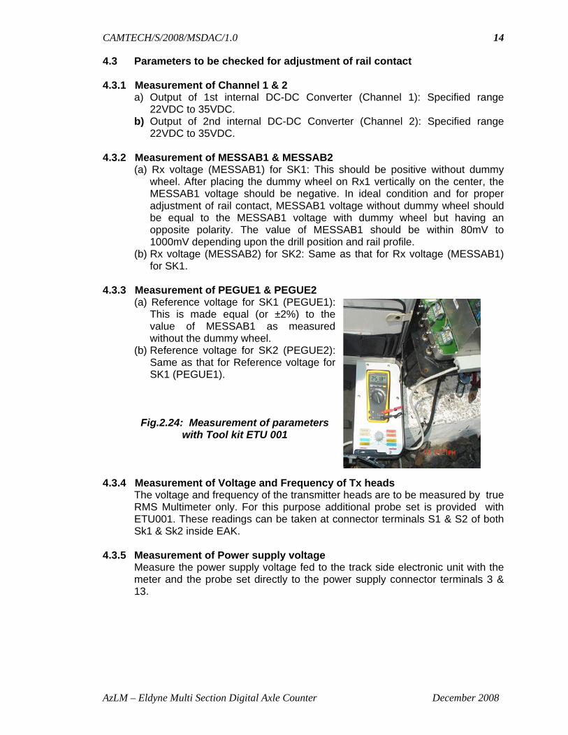
4.2.3 Selector Switch functions
• Selector switch position 1:Shows the value of the output of 1st internal DC-DC Converter (Channel1) in Analog card.
• Selector switch position 2: Shows the value of output voltage of 2nd internal DC-DC Converter (Channel2) in Analog card.
• Selector switch position 3: OFF • Selector switch position 4: Shows the rectified Rx voltage (MESSAB1) for
SK1. For fine adjustment the potentiometer R2 on the Analog board should be used.
R1 R2 R3 R4
Figure 2.22: Potentiometer for adjustment
• Selector switch position 5: Shows the value of reference voltage for SK1 (PEGUE1). This can be adjusted by the potentiometer R1 on the Analog board.
• Selector Switch position 6 – OFF. • Selector switch position 7: Shows the rectified Rx voltage (MESSAB2) for
SK2. For fine adjustment the potentiometer R4 on the Analog board should be used.
• Selector switch position 8: Shows the reference voltage for SK2 (PEGUE2). This can be adjusted by the potentiometer R3 on the Analog board.
• Selector switch position 9: OFF
Fig.2.23: Selector Switch of Test Equipment
8
10
11
CAMTECH/S/2008/MSDAC/1.0
AzLM – Eldyne Multi Section Digital Axle Counter December 2008
14
4.3 Parameters to be checked for adjustment of rail contact 4.3.1 Measurement of Channel 1 & 2
a) Output of 1st internal DC-DC Converter (Channel 1): Specified range 22VDC to 35VDC.
b) Output of 2nd internal DC-DC Converter (Channel 2): Specified range 22VDC to 35VDC.
4.3.2 Measurement of MESSAB1 & MESSAB2
(a) Rx voltage (MESSAB1) for SK1: This should be positive without dummy wheel. After placing the dummy wheel on Rx1 vertically on the center, the MESSAB1 voltage should be negative. In ideal condition and for proper adjustment of rail contact, MESSAB1 voltage without dummy wheel should be equal to the MESSAB1 voltage with dummy wheel but having an opposite polarity. The value of MESSAB1 should be within 80mV to 1000mV depending upon the drill position and rail profile.
(b) Rx voltage (MESSAB2) for SK2: Same as that for Rx voltage (MESSAB1) for SK1.
4.3.3 Measurement of PEGUE1 & PEGUE2
(a) Reference voltage for SK1 (PEGUE1): This is made equal (or ±2%) to the value of MESSAB1 as measured without the dummy wheel.
(b) Reference voltage for SK2 (PEGUE2): Same as that for Reference voltage for SK1 (PEGUE1).
Fig.2.24: Measurement of parameters with Tool kit ETU 001
4.3.4 Measurement of Voltage and Frequency of Tx heads
The voltage and frequency of the transmitter heads are to be measured by true RMS Multimeter only. For this purpose additional probe set is provided with ETU001. These readings can be taken at connector terminals S1 & S2 of both Sk1 & Sk2 inside EAK.
4.3.5 Measurement of Power supply voltage
Measure the power supply voltage fed to the track side electronic unit with the meter and the probe set directly to the power supply connector terminals 3 & 13.

CAMTECH/S/2008/MSDAC/1.0
AzLM – Eldyne Multi Section Digital Axle Counter December 2008
15
4.4 Adjustment procedure
Connect the test equipment to the diagnostic port of EAK.
Fig.2.25:Connection to diagnostic port
Steps to adjust the rectified voltage: 4.4.1 Adjustment of MESSAB1
• Put Selector Switch to position 4. • Measure the rectified voltage with and without dummy wheel. • Turn Potentiometer R2 on the Analog board to positive max. • The rectified voltage without dummy wheel must be set to positive
maximum. • If there is a big difference between the positive value and the negative
value, move the Tx heads upward or downward along the serration and adjust to optimum position. Taking the transmitter head upwards increases the negative voltage and decreases the positive voltage and vice versa.
• Adjust using Pot. R2 such that rectified voltage with and without dummy wheel are absolute equal (equal but having opposite polarity). Tolerance <=30mV.
• After getting the positive and negative voltages within the above specified tolerance limit the tighten the transmitter head properly with the torque wrench set at 25 Nm.
4.4.2 Trolley suppression
For Trolley suppression to be effective, the positive voltage (without dummy wheel) should be greater than the negative voltage (with dummy wheel) by a value not less than 30 mV so that the rectified Rx voltage does not go to negative (Figure 2.25) with the specified trolley wheel. It is recommended that the adjustment should be done using a spoke trolley wheel that is normally used in the section.

CAMTECH/S/2008/MSDAC/1.0
AzLM – Eldyne Multi Section Digital Axle Counter December 2008
16
Figure 2.26: Voltage Pattern with a trolley wheel after adjustment 4.4.3 Adjustment of MESSAB2
Repeat the above procedure for MESSAB2 (using Selector Switch position 7, and Potentiometer R4 on the Analog board).
4.4.4 Adjustment of PEGUE1
• Put Selector Switch to position 5 • Measure voltage • Adjust using potentiometer R1 on analog board such that PEGUE1 =
MESSAB1(without dummy wheel) Tolerance +-2% 4.4.5 Adjustment of PEGUE2
• Repeat for PEGUE2 using Selector Switch position 8 and potentiometer R3 such that PEGUE2 = MESSAB2(without dummy wheel) Tolerance +-2%
Measure the power supply voltage fed to the track side electronic unit with the meter and the probe set directly to the power supply connector (Terminals 3 & 13 if superimposed power & data line is used and terminals 1 & 11 if otherwise). Note down the adjustment details carried out during installation or periodic maintenance for the detection point in the log-sheet for future reference.
5. Address Setting
Each EAK connected to the same ACE for a particular installation, must have an unique address. This address setting can be done by setting the DIP switches provided on the mother board as shown in Figure 2.26. The system will not work without proper address as defined in site specific software. The set of addresses assigned to the EAKs in the site specific software must be maintained during installation.
Ensure that the switches are firmly set to the correct position. Only insulated long needle like materials to be used to set the switches. • To set a ´1´ press switch to the end that is marked “1”. • To set a ´0´ press switch to the other end.

CAMTECH/S/2008/MSDAC/1.0
AzLM – Eldyne Multi Section Digital Axle Counter December 2008
17
Address Setting For EAK With HEX Address 0001
0 0 0 0 0 0 0 0 0 0 0 0 0 0 0 1 on both set of Dip switches
Address Setting For EAK With HEX Address 0002
0 0 0 0 0 0 0 0 0 0 0 0 0 0 1 0 on both set of Dip switches Figure 2.27 : Setting of Address
Switch S1 & S2 address for CPU 1, Switch S3 & S4 address for CPU 2 6. Diagnostics 6.1 LED indications on EAK
LEDs are provided on the Analog and Evaluator/Digital cards to indicate different status of the system.
LED indications on Analog card LED Colour Indication H1 - 1 Red On: Wheel on rail contact 1
Off: No wheel on rail contact 1 H1 - 2 Green Off: Wheel approaching
Flashing: Sensor voltage (MESSAB1) within tolerance no wheel approaching.
H2 - 1 Red On: Wheel on rail contact 2 Off: No wheel on rail contact 2
H2 - 2 Green Off: Wheel approaching Flashing: Sensor voltage (MESSAB2) within tolerance no wheel approaching.
H3 - 1 Red On: Voltage H24V out of tolerance. Off: Voltage H24V within tolerance.
H3 - 2 Green On: Voltage H5V O.K. Off: Voltage H5V not O.K.

CAMTECH/S/2008/MSDAC/1.0
AzLM – Eldyne Multi Section Digital Axle Counter December 2008
18
LED indications on Digital Card
LED Colour Indication Normal operation H1 - 1 Green Transmitting data Flashing H1 – 2 Green CPU1 indicates a
fault during self-test of Analog part
OFF
H2 – 1 Green Transmitting data Flashing H2 – 2 Green CPU2 indicates a
fault during self-test of Analog part
OFF
6.2 Diagnostics information through LED display of various boards of ACE 6.2.1 Power supply Board normal display
Fig. 2.28 : Power Supply Board
There are three LEDs on power supply card: LED1, LED 2 & LED 3
LED in LED out1 LED out2 Functiongreen green green Normal operation
green off green temarature too high, overload, overvoltage at output1
green green off temarature too high, overload at overvoltage output2
Green off offInput voltage too low, input
voltage too highoff green green not applicableoff green off not applicable
off off offno input voltage, input voltage
too low, input open, input voltage too high
Function of LEDs

CAMTECH/S/2008/MSDAC/1.0
AzLM – Eldyne Multi Section Digital Axle Counter December 2008
19
6.2.2 Serial I/O Board normal display
6.2.3 Parallel I/O Board normal display
Row Channel Colour Function1 1 & 2 Green External input 1 activated.2 1 & 2 Green External input 2 activated
(applicable for board with two inputs)
3 1 & 2 Green Section clear, relay picked up (voltage on relay).
1 Yellow Non-vital output 1 activated.2 Yellow Non-vital output 2 activated.1 Yellow Polling2 Yellow Polling
6 1 & 2 Green Don’t care
Function of LEDs
4
5
Fig. 2.29 : Parallel I/O Board
LED ISDN-link channel 1 LED ISDN-link channel 2
• on for link state “connected”(if the ISDN link to the associated detection point is operational)
• otherwise off LED ISDN-telegram channel 2 LED ISDN-telegram channel 1
• flashes while receiving an ISDN-telegram(if a valid ISDN telegram was received from the associated detection point)
• otherwise off The serial I/O interface consists of two independent ISDN transmission paths and one I/O board is used for maximum two detection points. Fig. 2.28 : Serial I/O Board
Channel 1 Channel 2
1 2
3 4 5 6 Key Switch (not provided in new version) Push Button(not provided in new version) The control circuits of the parallel serial I/O boards are divided into Channels 1 and 2.

CAMTECH/S/2008/MSDAC/1.0
AzLM – Eldyne Multi Section Digital Axle Counter December 2008
20
6.2.4 Computer Board normal display
1
2 3
4
5
Fig. 2.30 : Computer Board 6.3 System Diagnostics by computer
For AzLM, the main diagnostic tool is the PC, loaded with diagnostic software. The diagnostic PC must be a Pentium PC having a serial interface RS-232 (19200 bps) port with Windows operating system. The serial interface has to be connected to the serial interface port on the CPU Card 1 of ACE by a Null modem cable. After running the diagnostic software, the system data can be downloaded and analyzed on the PC. (User’s manual may be referred). Note:The null modem cable should not always be kept connected at the CPU card end as well at the diagnostic PC end.
7. Reset Box
Fig. 2.32: Front Panel of Reset Box (ERBM-02)
1. Push Switch 2. Reset Counter 3. Preparatory Reset Indication – Green LED 4. Line Verification Indication – Yellow LED 5. Section Clear / Unoccupied Indication - Green LED 6. Section Closed / Occupied Indication - Red LED
1. Ethernet interface 2. Reset Button 3. LED 1…4
LED1: The flashing LED shows the communication on the Ethernet interface. LED2 & 3: Flashing LEDs show the communication between the processors. In normal condition, both LEDs flash. LED4: Not used.
4. Alphanumeric display The display shows a rotating bar if the CPU is operational
5. Diagnostic interface The serial interface socket to which the serial interface of the diagnostic PC is connected.
Fig. 2.31: System diagnostics by computer

CAMTECH/S/2008/MSDAC/1.0
AzLM – Eldyne Multi Section Digital Axle Counter December 2008
21
ERBM-02 is the reset box/module for Alcatel’s Multi Section Digital Axle Counters AzLM. It provides the basic resetting pulse (24VDC) for 3 seconds (approximately) to ACE to reset a particular section.
Fig. 33: SM’s Key Module
This Reset Key acts as the common key for all the reset boxes used in a particular installation. Additionally a buzzer is provided to give audio indication that the 3-second reset pulse is on.
7.1 Steps to initiate a reset
1. Insert the KEY, turn it clockwise and then push. Simultaneously, insert and turn the Cooperative reset key if provided. (H & R are to be shorted at selection jumper J1 on PCB if the Cooperation / Line verification is required otherwise P & R are to be shorted).
2. While KEY is in turned and pressed position, press the Reset Push Button for a specific section momentarily.
3. BUZZER sounds for 3 seconds and then stops. 4. Turn back the KEY anti-clockwise and take out.
Each reset is registered in the sealed reset COUNTER unit. The count increases by one after each reset commanded by the operator.
For more details Az LM Installation Guideline along with Pre-commissioning Check list for AzLM V5.1.2 may be referred.
1. Reset Key 2. Power On LED Indication (Yellow LED)

CAMTECH/S/2008/MSDAC/1.0
AzS350U- Siemens Multi Section Digital Axle Counter December 2008
1
PART - C
AzS350 U SIEMENS MULTI SECTION DIGITAL AXLE COUNTER
1. Introduction
This part explains the working and guidelines for installation, commissioning, adjustment and maintenance of AzS350U micro computer axle counting system from M/s Siemens.
STEU STEU
SIRIUS2
Inputs:AzGrT, vAzGrT;
AzGrH
Indo
or e
quip
men
tIn
ter-
lock
ing
TVDS A
VAU VAU
Outputs:Cl, ¬Cl, RR, RA
Inputs and outputs:user-definedinformation
3rd BLEA12
1st BLEA12
4th BLEA12
2nd BLEA12
Az
S 3
50 U
OtherAz S 350 U
systems
ServicePC
Out
door
equi
pmen
t
V iamodem
Null modem cable
OptionalAzGrH Auxiliary axle count reset buttonAzGrT Axle count reset buttonCl Track clear / occupied indicationRA Reset acknowledgementRR Reset restrictionTVDS Track vacancy detection sectionvAzGrT Preparatory axle count reset buttonZP 43 Wheel detection equipment (counting head)
TVDS DTVDS CTVDS B
ZP 43
1st VESBA 5th VESBA2nd VESBA 3rd VESBA 4th VESBA
ZP 43 ZP 43 ZP 43 ZP 43
1st BLEA12 pair
2nd BLEA12 pair
SIMISChannel 1
SIMIS Channel 2
OtherAz S 350systems
DIGIDO Internal connector 22
Two-
core
shi
elde
d ca
ble
Fig. 3.1. Structure of AzS350 U
1.1 Outdoor Equipment
The outdoor equipment is the ZP 43 wheel detection equipment (WDE) (counting head) comprising a double wheel detector and a trackside connection box. Counting heads are installed at the limits of a track vacancy detection section (TVDS).
1.2 Indoor Equipment
The indoor equipment consists of the evaluation computer which is installed near station.
The evaluation computer • evaluates the signals transmitted from the counting heads, • compares the number of axles counted into a track vacancy
detection section with the number of axles counted out, • monitors the track vacancy detection sections and generates a
track clear or occupied indication.

CAMTECH/S/2008/MSDAC/1.0
AzS350U- Siemens Multi Section Digital Axle Counter December 2008
2
2. Mode of Operation
When a wheel enters the sensing range of the double wheel detector, it modifies the strength of the alternating electro magnetic field thereby generating pulses. These pulses are transmitted via connecting cable to the evaluation computer. Following electrical isolation, the VESBA board forwards the WDE data via two independent channels. If the signal exceeds a defined limit after band-pass filtering (this is the case if the counting head is not passed – closed-circuit principle), a trigger stage responds and generates a digital "high" signal at the output of this board. In the case of wheel passage or signal failure, a "low" signal is generated.
The STEU control and diagnostic board receives the signal data. It stores the WDE signals and transfers them to the VAU processing and monitoring board. The SIMIS C microcomputers process and evaluate the axle counting data and forward the results to the higher-level interlocking circuits via the BLEA12 input / output board (relay outputs). The SIRIUS2 (serial computer interface universal) board is used to transmit WDE signals between two Az S 350 U.
3. Power Supply 3.1 Power Supply for Indoor equipment
Input Supply voltage to Evaluation computer is 24 VDC to 60 V DC (+20%/-10%). The SVK2150 power supply board generates the following operating voltages required by Az S 350 U: • 5 V DC for internal operation • 70 V DC for external operation of max. five counting heads
3.2 Power Supply for Outdoor equipment
WDE supply voltage at counting head – 30 to 72 V DC. As an option, the counting heads can be supplied with power directly from an on-site voltage source via an additional band-pass filter board for external supply (in the ZP 43 wheel detection equipment).
Option for external supply at counting head – 42 to 50 V DC. 4. Double Usage of Counting Heads
When using the double-usage function, the WDE signals of one counting head are jointly used by two adjacent evaluation computers. This function results in economy of counting heads, ensuring at the same time continuous track vacancy detection. There are three types of double usages: • Analogue double usage • Digital double usage • Double usage via SIRIUS2 Board

CAMTECH/S/2008/MSDAC/1.0
AzS350U- Siemens Multi Section Digital Axle Counter December 2008
3
4.1 Analogue double usage
The connection of a counting head (outdoor equipment) to two evaluation computers (indoor equipment) is called analogue double usage. A supplementary board in the trackside connection box of the counting head permits the analogue WDE signals to be transmitted to both evaluation computers. An additional cable is required between the counting head and the second evaluation computer.
4.2 Digital double usage For digital double usage of a counting head (outdoor equipment), digitised WDE signals are transmitted between two interconnected evaluation computers (indoor equipment). By interconnecting evaluation computers, the signals of a counting head can also be used by a second evaluation computer. No additional cabling between indoor and outdoor equipment is required for this multiple usage of WDE signals.
4.3 Double usage via SIRIUS2 Board
WDE signals can also be jointly used by connecting two evaluation computers via a SIRIUS2 board (V.24 interfaces). In addition to the WDE data of up to five directly connected counting heads, this mode of connection permits the WDE information of up to six counting heads of an adjacent evaluation computer to be also used.
5. Installation Installation must be done in accordance with RDSO approved pre-
commissioning checklist for the equipment. 5.1 Installation of outdoor equipments
The ZP 43 wheel detection equipment (counting head) is installed at the limits of a track section. It comprises: • DEK 43 double wheel detector with connecting cables to the
trackside connection box (approx. 5 m long, optionally 10 m) • Trackside connection box
The ZP 43 wheel detection equipment is connected to the evaluation computer via two wires of a star-quad railway signalling cable. This cable is used to transmit the WDE signals to the evaluation computer and to supply the counting head with power (if it is not supplied from an external voltage source).

CAMTECH/S/2008/MSDAC/1.0
AzS350U- Siemens Multi Section Digital Axle Counter December 2008
4
Key:DEK 43 = Double wheel detectorRx1, Rx2 = ReceiversT = TransformerTCB = Trackside connection box Tx1, Tx2 = Transmitters
Rx1 Rx2
VDC
VDC
VDC
Vf1
f2V
Evaluation computer
DEK 43
DCDC
T
Generator43 kHz
Voltageconverter
f1 f2
ZP 43
Signalling cable,paired or star-quad
Connecting cables
Vf
Receiving amplifier
Filter
Amplifier
Rectifier
Voltage-frequencyconverterBand-pass filter
TCB
Vf
Tx1 Tx2
VDC = Supply voltageVf1 = Signal voltage f1Vf2 = Signal voltage f2ZP 43 = Wheel detection equipment
Fig.3.2. Block diagram of ZP43 Wheel detection equipment
5.1.1 DEK 43 Double Wheel Detector
The DEK 43 double wheel detector (IP68) consists of two electronic sensors. Each sensor has a transmitter and a receiver section. The transmitters and receivers of both sensors are accommodated in one housing each. The transmitter housing is located on the outer side and the receiver housing on the inner side of the rail. In order to reduce interference from the rail, e.g. through traction return currents, the transmitter and receiver are provided with a reducing plate on the side facing the rail. The reducing plate is shaped to match the rail profile and extends from the base of the rail across the web to underneath the rail head. The double wheel detector is attached by means of two mushroom-head screws through centred holes in the neutral zone of the rail web.

CAMTECH/S/2008/MSDAC/1.0
AzS350U- Siemens Multi Section Digital Axle Counter December 2008
5
Fig 3.3 (a) Installation between Sleepers
For UIC 60 : Height X= 85 mm
For 52 kg: Height X= 69 mm
For 90 lbs: Height X= 56 mm
Fig 3.3(b) Double wheel detector components
1. Inner side of rail 2. Outer side of rail 3. Transmitter 4. M12 Hexagonal nut 5. Spring washer 6. Square washer 7. Mushroom head bolt 8. Receiver 9. Reducing plate

CAMTECH/S/2008/MSDAC/1.0
AzS350U- Siemens Multi Section Digital Axle Counter December 2008
6
5.1.2 Connecting Cables
Shielded connecting cables are used to connect the double wheel detector and the track side connection box. They are approximately 05 meter long (alternatively 10 meters.).
Transmitter
Reducing plates
Receiver
ZP 43 trackside connection box
Transmitter / receivercable with flexibletubing
Flexible tubingfor signallingcable
Pipe support
Fig 3.4 Connection between DEK43 and track side connection box
5.1.3 Trackside Connection Box
Two variants of the trackside connection box are available, variant E (cast-aluminium housing) and V (plastic housing). Both variants of the trackside connection box are air-tight (IP67) and have a removable, lockable cover. For trackside installation, pipe supports of various heights are available. The connection box is equipped with cable glands of various diameters to allow cables to be led into or brought out of the box. A mounting rack is installed in the trackside connection box. The electronic components required for controlling the double wheel detector and pre-processing the detector information is accommodated on plug-in circuit boards.
Fig 3.3(c) Installation of DEK43 double wheel detector

CAMTECH/S/2008/MSDAC/1.0
AzS350U- Siemens Multi Section Digital Axle Counter December 2008
7
Frequency tuning board 1: Connection for WDE service equipment 2: Lightning protection board (core-to-core)
3: Generator board 4: Band-pass filter board or band-pass filter board for external supply
Si1
f2
6,52
f1
3,6
0,1 A
5: Supplementary board for WDE double usage
or jumper board
Fig 3. 5 (a) Variant E
Adjusting control for signal frequency 2 (6.52 kHz) Rotary switch (S1) for transmitter frequency (43 kHz
Adjusting control for signal frequency 1 (3.60 kHz)
3 4 5
1
1:
3:
4:
Wiring backplane including overvoltage protectionand tuning components (core-to-core) Connection for WDE service equipmentBand-pass filter board or band-pass filter board for external supplyGenerator board with adjusting controls forsignal frequencies
2:
5:
Supplementary board for WDE double usage
2
Fig 3.5(b) Variant V

CAMTECH/S/2008/MSDAC/1.0
AzS350U- Siemens Multi Section Digital Axle Counter December 2008
8
Fig 3.5(c) Termination details of track side connection box
Fig 3.5(d) Track side connection box installation

CAMTECH/S/2008/MSDAC/1.0
AzS350U- Siemens Multi Section Digital Axle Counter December 2008
9
5.1.4 Permissible distances Permissible distance between double wheel detector of same
design When both wheel detectors are installed on the same rail the distance between them should be more than 5 metre. When wheel detectors are installed on the opposite rails, the horizontal distance between the wheel detectors should be more than 1 metre.
Permissible distances between double wheel detectors in point zone The distance between any two detectors should be more than 1 metre.
Permissible distances between double wheel detectors and tuning unit of AFTC The double wheel detector should be installed more than 1 metre away from the boundary of tuned zone of tuning unit. The distance between two wheel detectors on either side of the tuning unit shall not be less than 5 metre.
Permissible distances between double wheel detectors and track magnet of AWS The double wheel detectors should be installed more than 0.7 metre away from the track magnet of AWS.
5.1.5 External Power Supply for ZP 43 (Optional)
The wheel detection equipment can also be supplied externally with DC voltage or AC voltage. External supply is required if evaluation computer and wheel detection equipment are a great distance apart. In this case, the wheel detection equipment cannot be supplied via the core pair which carries the WDE signals. Power must be supplied via a second core pair or a different cable. It must be uninterruptible.
5.1.6 Double Usage for ZP 43 (Optional)
Using a supplementary board (mounting location 5) in the trackside connection box, the analogue WDE signals are provided twice, allowing wheel detection equipment to interoperate with two neighbouring evaluation computers, i.e. double usage of the wheel detection equipment is possible.
5.1.7 Over voltage Protection for ZP 43
Some users of axle counting systems have particularly high electromagnetic interference, due to atmospheric conditions, e.g. thunderstorms, and technical conditions, such as traction currents. The overvoltage protection units already available in the wheel detection equipment (overvoltage protection in connecting cables – core-to-core) can be supplemented by additional overvoltage protection measures (core-to-earth).

CAMTECH/S/2008/MSDAC/1.0
AzS350U- Siemens Multi Section Digital Axle Counter December 2008
10
Irrespective of whether or not the additional over-voltage protection system is used, the trackside connection box must always be earthed. Over-voltage protection components are available for both variants of ZP 43 equipment.
5.2 Installation of indoor equipments
Evaluation computer is the heart of the AzS350U Axle counter system. It consists of SIMIS fail safe microcomputer system from M/s Siemens.
5.2.1 AzS350U Axle counting cabinets
The cabinets accommodates the required number of evaluation computers mounting frames (ECMF). Optional components such as ventilator sub assemblies, compartment basis and terminal modules are installed depending upon the cabinet type.
Axle counting cabinet S25552-J605-U1
This cabinet can accommodate a maximum of six evaluation computers mounting frames. Connection of counting heads: Within the cabinet, connecting cables lead from the backplane connectors of the evaluation computer mounting frame to the counting head terminals on the mounting plate. The cable connection to the intermediate distribution rack is made during installation on site.
Connection of BLEA12 boards: Within the cabinet, connecting cables lead from the front connectors of the BLEA12 boards to terminal blocks (MOKAU). On the MOKAU modules, there are fuse holders for the outputs of the BLEA12 board. The cable connection from the terminal blocks to the intermediate distribution rack is made during installation on site. Axle Counting Cabinet S25552-J605-U2 This cabinet can accommodate a maximum of nine evaluation computers mounting frames.
Fig 3.6 Cabinet S25552-J605-U1
Fig 3.7 Cabinet S25552-
J605-U2

CAMTECH/S/2008/MSDAC/1.0
AzS350U- Siemens Multi Section Digital Axle Counter December 2008
11
Two variants for connecting counting heads: The first variant permits connection via cables with backplane connectors directly to the intermediate distribution rack. For the second variant, the counting head connections are run via an optional terminal strip in the lower part of the cabinet using backplane connectors already during cabinet assembly. Connection of BLEA12 boards: Ready-made connecting cables with front connectors in the required cable lengths permit the BLEA12 boards to be directly and cost-effectively connected to the intermediate distribution rack (different cable variants for the first and the second pair of BLEA12 boards).
6. Overview of Boards
The plug in circuit boards are accommodated in a single tier mounting frame with wiring blackplane. Dummy boards are inserted in free slots for optional boards.
Fig. 3.8 Front view of AzS350 U evaluation computer (including slot numbers)
6.1 SIRIUS2 (serial computer interface universal) board
The SIRIUS2 (serial computer interface universal) board enables communication between the connected evaluation computers. It provides two serial, bidirectional interfaces for data transmission, each equipped with a V.24 output. The SIRIUS2 board is used on one channel only.
6.2 BLEA12 boards
All inputs and outputs (CI, ¬CI, AzGrT or vAzGrT, RR, RA, user-defined block information) to and from the interlocking are done via the BLEA12 block input / output board. Two BLEA12 boards (first pair of BLEA12 boards) are required for the dual-channel Az S 350 U, one for channel 1 and one for channel 2. A second, optional pair of BLEA12 boards can be inserted.

CAMTECH/S/2008/MSDAC/1.0
AzS350U- Siemens Multi Section Digital Axle Counter December 2008
12
6.3 STEU control and diagnostic board
Each computer channel has a STEU control and diagnostic board, which evaluates the WDE signals received (counting head- and section-specific data).
6.4 VAU & CPU board
The VAU processing and monitoring board, a CPU board, constitutes the fail-safe microcomputer system (SIMIS C computer core). The VAU board provides monitoring and comparator functions for synchronous dual-channel microcomputer operation.
6.5 VESBA board
Each directly connected counting head requires one VESBA amplifier, trigger and band-pass filter board (numbering of counting heads: CH 1 to CH 5). It provides electrical isolation between indoor and outdoor equipment (counting head). The VESBA board splits the signal frequencies f1 and f2 into two independent channels and filters, amplifies, rectifies and evaluates (trigger) the data transmitted from the counting head.
6.6 DIGIDO Board
The DIGIDO digital double-usage board is used if WDE information is to be jointly used by two evaluation computers.
6.7 SVK2150 Power Supply Board
The SVK2150 power supply board provides 5 V for the evaluation computer and 70 V for the counting heads.
The brief summary of Az S 350 U components is tabulated below:
Quantity Short name Designation 1 MF Mounting frame 2 VAU* Processing and monitoring board 2 STEU* Control and diagnostic board 2 or 4 BLEA12* Block input / output board 0 or 1 SIRIUS2 Serial computer interface universal board 0 to 5 VESBA Amplifier, trigger and band-pass filter board 0 or 1 DIGIDO Digital double-usage board 1 SVK2150 Power supply board *Computer core: boards for channel 1 and channel 2; at least two BLEA12 boards necessary
CAMTECH/S/2008/MSDAC/1.0
AzS350U- Siemens Multi Section Digital Axle Counter December 2008
13
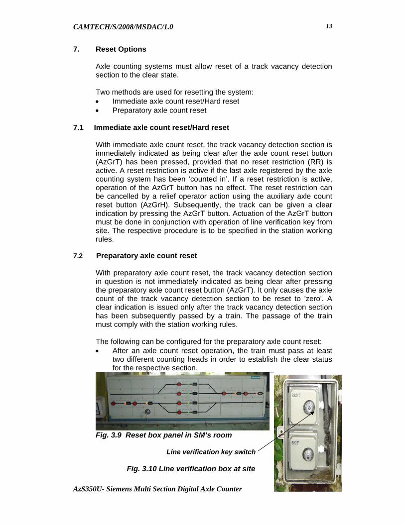
7. Reset Options
Axle counting systems must allow reset of a track vacancy detection section to the clear state. Two methods are used for resetting the system: • Immediate axle count reset/Hard reset • Preparatory axle count reset
7.1 Immediate axle count reset/Hard reset
With immediate axle count reset, the track vacancy detection section is immediately indicated as being clear after the axle count reset button (AzGrT) has been pressed, provided that no reset restriction (RR) is active. A reset restriction is active if the last axle registered by the axle counting system has been ‘counted in’. If a reset restriction is active, operation of the AzGrT button has no effect. The reset restriction can be cancelled by a relief operator action using the auxiliary axle count reset button (AzGrH). Subsequently, the track can be given a clear indication by pressing the AzGrT button. Actuation of the AzGrT button must be done in conjunction with operation of line verification key from site. The respective procedure is to be specified in the station working rules.
7.2 Preparatory axle count reset
With preparatory axle count reset, the track vacancy detection section in question is not immediately indicated as being clear after pressing the preparatory axle count reset button (AzGrT). It only causes the axle count of the track vacancy detection section to be reset to 'zero'. A clear indication is issued only after the track vacancy detection section has been subsequently passed by a train. The passage of the train must comply with the station working rules.
The following can be configured for the preparatory axle count reset: • After an axle count reset operation, the train must pass at least
two different counting heads in order to establish the clear status for the respective section.
Fig. 3.9 Reset box panel in SM’s room
Line verification key switch
Fig. 3.10 Line verification box at site

CAMTECH/S/2008/MSDAC/1.0
AzS350U- Siemens Multi Section Digital Axle Counter December 2008
14
• After an axle count reset operation, the train must pass all counting heads at the beginning and end of the track vacancy detection section in order to establish the clear status for the respective section. This may involve several individual train passages.
• After an axle count reset operation, the train must pass all counting heads passed during the last train passage in order to establish the clear status for the respective section.
8. Tools required for installation, testing, commissioning and maintenance
• Hole drilling machine
• 13 mm drill bit
• Spanners 19 and 13
• Torque wrench with 19” socket
• Screw driver 3/32” * 2”
• Multimeter for measurement of values
• Extension card for measurement.
9. Adjustment and commissioning 9.1 Adjustments to be done at the Outdoor junction Box
• Tighten the Counting Head nut with a torque wrench applying a torque of 75 Nm
• Switch on the Evaluation Computer in the relay room
• Adjust the Frequency Fs as close as possible to 43 KHz
• Adjust Frequency F1 to 3.50 KHz
• Adjust Frequency F2 to 6,37 KHz

CAMTECH/S/2008/MSDAC/1.0
AzS350U- Siemens Multi Section Digital Axle Counter December 2008
15
9.2 Central evaluator adjustments
After the outdoor adjustment the VESBA voltage (V1 & V2) in the evaluator has to be adjusted to 3 volts.
Si 1
0,2A
F/U
F/U
0 V
U
U
..
. .
Fig. 3.11 Adjustments at VESBA Board 9.3 Measurement of Parameters Readings to be taken at the outdoor junction box.
Observed Values Sr. No. Parameter Acceptable Range
CH1 CH2 CH3 CH4 CH5 CH61 U60 30 V TO 72 V DC
2 U24 21.3 V TO 22.4V DC
3 Fs (43 Khz) 42.8 to 43.2 KHz
4 F1 (3.50 Khz) 3.47 to 3.53 KHz
5 F2 (6.37 Khz) 6.31 to 6.43 KHz
6 UR1 3.25 V to 3.65 V DC
7 UR2 3.05 V to 3.45 V DC
8 UE1 60 to 150 mv (AC)
9 UE2 60 to 150 mv (AC)
Counting head fuse (0.2 A) Counting head (systems 1 and 2 of double wheel detector) System 1 LED (yellow) lights up when system 1 of double wheel detector is passed or occupied (or V1< 1.3 V DC) Potentiometer for voltage adjustment V1 = 3.0 V DC ± 0.10 V Measuring socket for signal frequency F1 = 3.60 kHz ± 0.05 kHz (freq. adjusted at counting head) Measuring socket for voltage V1 = 3.0 V DC ± 0.10 V 0 V measuring sockets for both systems
System 2 Measuring socket for signal frequency F2 = 6.52 kHz ± 0.10 kHz (freq. adjusted at counting head) Measuring socket for voltage V2 = 3.0 V DC ± 0.10 V LED (yellow) lights up when system 2 of double wheel detector is passed or occupied (or V2< 1.3 V DC) Potentiometer for voltage adjustment V2 = 3.0 V DC ± 0.10 V

CAMTECH/S/2008/MSDAC/1.0
AzS350U- Siemens Multi Section Digital Axle Counter December 2008
16
Readings to be taken at the evaluation computer. Observed Values Sr.N
o. Parameter Acceptable Range CH1 CH2 CH3 CH4 CH5 CH6
1 Signal F1 2.9 to 3.1 V DC 2 Signal F2 2.9 to 3.1 V DC
Fig.3.12(a) Measurement of U60
Fig.3.12(b) Measurement of Fs
Fig.3.13 Measurement of F1

CAMTECH/S/2008/MSDAC/1.0
AzS350U- Siemens Multi Section Digital Axle Counter December 2008
17
10. Maintenance 10.1 ZP43 Wheel detection equipment
Wheel detection equipment shall be inspected
• Every twelve months for high traffic density lines • Every eighteen months for other lines
Scope of inspection • Visual inspection of all parts for damage and secure fittings • Check parameters as given in para 9.3. • Only electrical re adjustments are to be performed if the value do
not come with in acceptable range.
10.2 Diagnostics 10.2.1 Out door equipment
Outdoor equipment-related adjustment and control measurements are performed with the help of WDE test equipment. ZP 43 E / V provides a mounting location for this purpose. The equipment is connected via a plug-in connection for diagnostic purposes. In case of failure when rapid and precise fault location is required, the tests can be performed without altering any of the Az S 350 U components, i.e. without disconnecting cables or removing boards. The following test equipment is used: Test adapter board The test adapter board can be used during commissioning and maintenance for testing and adjusting work on the wheel detection equipment. The necessary voltage and frequency measurements can be performed using a commercially available multi-meter. The front panel of the board has measuring sockets arranged in pairs to which the multi-meter can be connected. The test adapter board is inserted in the corresponding mounting location in the trackside connection box of the ZP 43 E / V wheel detection equipment.
Fig.3.14 Test adapter board with measuring
sockets

CAMTECH/S/2008/MSDAC/1.0
AzS350U- Siemens Multi Section Digital Axle Counter December 2008
18
10.2.2 Indoor Equipment
The front panels of the boards are fitted with light-emitting diodes (LEDs) indicating the status or cause of possible faults of the axle counting system. In addition, the LEDs provide statistical information, e.g. the number of track section occupancies or the number of axles having passed a counting head. With its additional service PC, the system enables maintenance activities to be carried out in a most effective manner.
Using the service PC, the information of up to nine evaluation computers can be evaluated. For this purpose, the service PC is connected to the serial interface (SIRIUS2 board) of the evaluation computer. Eight evaluation computers can be serially connected via a converter. The ninth evaluation computer is connected directly to the free serial interface of the service PC.
A standard PC is used as the hardware platform. A PC or a laptop can be connected, depending on the environmental conditions on site. The following information of the connected evaluation computers is displayed via the diagnostic software:
• all nine ECs: clear / occupied state of each TVDS • one EC at a time: TVDS, CH, axle count, error count
Remote diagnostics via modem is also possible with the service PC. The relevant information is transferred to a maintenance centre for analysis by maintenance staff. The mode of visualisation is the same as on the service PC on site. The information given by some of the boards through LED display is given below. VAU Board
VGL = Comparator (yellow LED)
SPW = Voltage controller (red LED)
PAB = Program-controlled shutdown (red LED)
ANL = Start-up (red LED)
Red button = System reset
VGL
SPWPABANL
Fig. 15 VAU Board Normal
Display

CAMTECH/S/2008/MSDAC/1.0
AzS350U- Siemens Multi Section Digital Axle Counter December 2008
19
STEU Board
Lit LEDs
2 xx
0123456789
1011
Diagn.
0 - System reset performed, pressing of AzGrT required1 - Minus axle blocking effective; counting capacity exceeded; undefined counting pulse2 - Count monitoring3 - Faulty telegram transmission between evaluation computers or the second evaluation computer is shut down4 - Reset restriction (RR) effective5 - Section occupied, axle count not equal to 0 or another LED is on
6 - As for LEDs 0 to 5 of TVDS 1 7 - "8 - " 9 - " 10 - " 11 - "
2 xx
0123456789
1011
Diagn.
Display TVDS 1
Display TVDS 3
STEU 1Channel 1(left board)
2 xx
0123456789
1011
Diagn.
Display TVDS 2
DisplayTVDS 4
STEU 2Channel 2
(right board)
TVDS 4 not configuredDisplay of
telegram transmission state
Mea
ning
of L
EDs
for T
VDS
1 M
eani
ng o
f LED
s fo
r TVD
S 3
Lit LEDs
0 - As for LEDs 0 to 5 of TVDS 1 1 - "2 - " 3 - " 4 - " 5 - "
6 - As for LEDs 0 to 5 of TVDS 1 7 - "8 - " 9 - " 10 - " 11 - "
Mea
ning
of L
EDs
for T
VDS
2M
eani
ng o
f LED
s fo
r TVD
S 4
TVDS 4 not configured7 - LEDs 7 to 9:8 - Display of telegram9- transmission state
Fig.16 (a) Front view of STEU Board, display of operating state for Track vacancy detection section (TVDS) 1 to 4.
STEU 1Channel 1(left board)
STEU 2Channel 2
(right board)
2 xx
0123456789
1011
Diagn.
2 xx
0123456789
1011
Diagn.
LEDs for statistics function selection
STEU 1Channel 1(left board)
STEU 2Channel 2
(right board)
2 xx
0123456789
1011
Diagn.
2 xx
0123456789
1011
Diagn.
Display of selectedstatistics function
Display of resultfor selected
statistics function
LED
s fo
rdi
spla
y of
resu
lts
LEDs forobject selection
Select withAzGrH button
Result
Display of selected object(CH, TVDS, block information
or system information selectable)
Fig.16 (b) Front view of STEU Board, Statistics
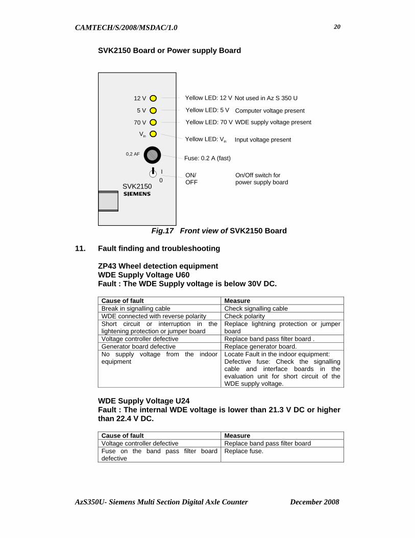
CAMTECH/S/2008/MSDAC/1.0
AzS350U- Siemens Multi Section Digital Axle Counter December 2008
20
SVK2150 Board or Power supply Board
SVK2150
12 V
I0
ON/OFF
On/Off switch forpower supply board
0,2 AF
5 V
70 V
Vin
Yellow LED: 12 V Not used in Az S 350 U
Yellow LED: 5 V
Yellow LED: 70 V
Yellow LED: Vin
Fuse: 0.2 A (fast)
Computer voltage present
WDE supply voltage present
Input voltage present
Fig.17 Front view of SVK2150 Board
11. Fault finding and troubleshooting
ZP43 Wheel detection equipment WDE Supply Voltage U60 Fault : The WDE Supply voltage is below 30V DC.
Cause of fault Measure Break in signalling cable Check signalling cable WDE connected with reverse polarity Check polarity Short circuit or interruption in the lightening protection or jumper board
Replace lightning protection or jumper board
Voltage controller defective Replace band pass filter board . Generator board defective Replace generator board. No supply voltage from the indoor equipment
Locate Fault in the indoor equipment: Defective fuse: Check the signalling cable and interface boards in the evaluation unit for short circuit of the WDE supply voltage.
WDE Supply Voltage U24 Fault : The internal WDE voltage is lower than 21.3 V DC or higher than 22.4 V DC.
Cause of fault Measure Voltage controller defective Replace band pass filter board Fuse on the band pass filter board defective
Replace fuse.

CAMTECH/S/2008/MSDAC/1.0
AzS350U- Siemens Multi Section Digital Axle Counter December 2008
21
Transmitter frequency fs Fault: Transmitter frequency is out of the tolerance range. Frequency adjustment is not possible.
Cause of fault Measure Generator defective Replace generator board Lightning protection elements defective Replace lightning protection board Frequency tuning board defective Replace mounting frame Double wheel detector (transmitter) defective
Replace double wheel detector (transmitter)
Signal frequencies f1 and f2 Fault: Signal frequency f1 and f2 is out of the tolerance range.
Cause of fault Measure Double wheel detector loose Firmly tighten the fastening bolts.
Readjust transmitter frequency fs and signal frequencies f1 and f2.
Double wheel detector is installed incorrectly
Install double wheel detector correctly.
Receiver voltage UE1 and UE2 Fault: Receiver voltages are less than 60 mV.
Cause of fault Measure Double wheel detector is defective or loose
Firmly tighten the fastening bolts or replace double wheel detector
The Double wheel detector is installed on a very high rail section
Check the double wheel detector for correct installation (drilling dimensions, secure fit of the screws, no stray metal parts in the vicinity). If UE1 and UE2 are at the least 54 mV and it is possible to adjust the signal frequencies to the set point no further measures are required.
Evaluation computer
VESBA Board
Fault: Yellow LED of the VESBA card is continuously lit (i.e. no wheel on the detection point) Cause of fault Measure There is a fault at the counting head Check the counting head for loose nut.
Check if the frequencies f1 and f2 are in the given range. Check the fuse on the junction box.
The VESBA voltage is not adjusted to 3V.
Adjust the VESBA voltage to 3V. Check the fuse on the VESBA module.
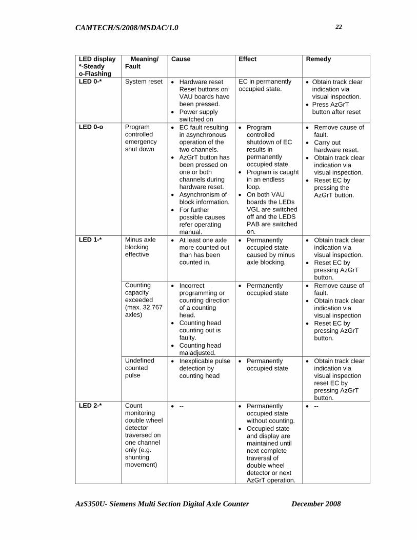
CAMTECH/S/2008/MSDAC/1.0
AzS350U- Siemens Multi Section Digital Axle Counter December 2008
22
LED display *-Steady o-Flashing
Meaning/ Fault
Cause Effect Remedy
LED 0-* System reset • Hardware reset Reset buttons on VAU boards have been pressed.
• Power supply switched on
EC in permanently occupied state.
• Obtain track clear indication via visual inspection.
• Press AzGrT button after reset
LED 0-o Program controlled emergency shut down
• EC fault resulting in asynchronous operation of the two channels.
• AzGrT button has been pressed on one or both channels during hardware reset.
• Asynchronism of block information.
• For further possible causes refer operating manual.
• Program controlled shutdown of EC results in permanently occupied state.
• Program is caught in an endless loop.
• On both VAU boards the LEDs VGL are switched off and the LEDS PAB are switched on.
• Remove cause of fault.
• Carry out hardware reset.
• Obtain track clear indication via visual inspection.
• Reset EC by pressing the AzGrT button.
Minus axle blocking effective
• At least one axle more counted out than has been counted in.
• Permanently occupied state caused by minus axle blocking.
• Obtain track clear indication via visual inspection.
• Reset EC by pressing AzGrT button.
Counting capacity exceeded (max. 32.767 axles)
• Incorrect programming or counting direction of a counting head.
• Counting head counting out is faulty.
• Counting head maladjusted.
• Permanently occupied state
• Remove cause of fault.
• Obtain track clear indication via visual inspection
• Reset EC by pressing AzGrT button.
LED 1-*
Undefined counted pulse
• Inexplicable pulse detection by counting head
• Permanently occupied state
• Obtain track clear indication via visual inspection reset EC by pressing AzGrT button.
LED 2-* Count monitoring double wheel detector traversed on one channel only (e.g. shunting movement)
• -- • Permanently occupied state without counting.
• Occupied state and display are maintained until next complete traversal of double wheel detector or next AzGrT operation.
• --

CAMTECH/S/2008/MSDAC/1.0
AzS350U- Siemens Multi Section Digital Axle Counter December 2008
23
LED display *-Steady o-Flashing
Meaning/ Fault
Cause Effect Remedy
Count monitoring counting head fault due to spurious pulse
• Double wheel detector, after complete traversal, detected pulses on one channel only (more than 4ms.)
• Double wheel detector during a traversal detected pulse due to spurious pulses (more than 4ms)
• Double wheel detector without a traversal detected pulses due to spurious pulse (more than 4ms)
• Counting error leading to a permanently occupied state
• No counting error, at least one axle follows after the cause the track clear indication will be given after the train has passed display is switched off.
• Occupied state without a train, occupied state and display are maintained until next traversal with track clear indication or until next AzGrT operation.
• Check counting head concerned including cable.
• Obtain track clear indication via visual inspection
• Reset EC by pressing AzGrT button.
LED 3 -* Telegram transmis-sion faulty or switched off
• Data transmission between Ecs is fully faulty.
• Second EC has been switched off.
• Second EC is in emergency shutdown state.
• Data transmission between Ecs was faulty (DIP switch TELFM is set to off and double wheel detector detected no pulses).
• As long as the connection is interrupted or faulty data is received the TVDS with remote counting heads remain in the occupied state.
• Occupied state and display are maintained until next complete traversal of double wheel detector or next AzGrT operation (DIP switch TELFM set to off).
• Check connection between Ecs
• Check whether second EC has been switched off or is in an emergency shut down state (restart).
• Reset EC by pressing AzGrT button.
• Wait for train run. If TVDS remain occupied perform the measures above.
LED 4-* Reset restriction (RR)
• One counting head of the TVDS detected pulses.
• There are axles in the TVDS.
• Time frame for simultaneous AzGrT operation exceeded (single channel operation).
• RR effective and section is occupied.
• Cancel RR via AzGrT button after section clear proving (according to station working rules).
• If time frame was exceeded restart EC (after consultation with SM).
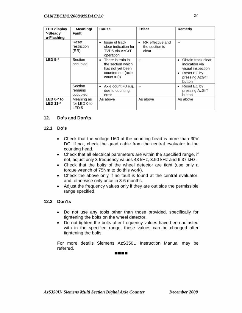
CAMTECH/S/2008/MSDAC/1.0
AzS350U- Siemens Multi Section Digital Axle Counter December 2008
24
LED display *-Steady o-Flashing
Meaning/ Fault
Cause Effect Remedy
Reset restriction (RR)
• Issue of track clear indication for TVDS via AzGrT operation
• RR effective and the section is clear.
--
Section occupied
• There is train in the section which has not yet been counted out (axle count = 0)
-- • Obtain track clear indication via visual inspection
• Reset EC by pressing AzGrT button
LED 5-*
Section remains occupied
• Axle count =0 e.g. due to counting error
-- • Reset EC by pressing AzGrT button
LED 6-* to LED 11-*
Meaning as for LED 0 to LED 5
As above As above As above
12. Do’s and Don’ts 12.1 Do’s
• Check that the voltage U60 at the counting head is more than 30V DC. If not, check the quad cable from the central evaluator to the counting head.
• Check that all electrical parameters are within the specified range, if not, adjust only 3 frequency values 43 kHz, 3.50 kHz and 6.37 kHz.
• Check that the bolts of the wheel detector are tight (use only a torque wrench of 75Nm to do this work).
• Check the above only if no fault is found at the central evaluator, and, otherwise only once in 3-6 months.
• Adjust the frequency values only if they are out side the permissible range specified.
12.2 Don’ts
• Do not use any tools other than those provided, specifically for
tightening the bolts on the wheel detector. • Do not tighten the bolts after frequency values have been adjusted
with in the specified range, these values can be changed after tightening the bolts.
For more details Siemens AzS350U Instruction Manual may be referred.

CAMTECH/S/2008/MSDAC/1.0
Annexure – Digital Axle Counter (Multi Section) December 2008
ANNEXURE I
MAINTENANCE LOG-SHEET FOR ELDYNE MSDAC
Railway…………………… Division………………… Station…………… DP No………… Track Section…………….
Date………… Item Permissible range Recorded value
1 a) Power supply Channel 1 22…35 VDC 2 b) Power supply Channel 2 22…35 VDC
c) ( Rectified Rx1 voltage w/o dummy wheel ) MESSAB1
+80..+1000mV DC 4
(d) With dummy wheel set on 40 mm
-80..-1000mV DC
5 (e) Reference voltage PEGUE1 Adjust as per (c) (f) ( Rectified Rx1 voltage w/o dummy wheel ) MESSAB2
+80..+1000mV DC 7
(g)With dummy wheel set on 40 mm
-80….-1000mV DC
Selector position
in test
unit
8 h)Reference voltage PEGUE2 Adjust as per (f) Terminal 3 & 13 of EAK
i) Input Power supply voltage 54 V to 72 V DC
(j) Transmitter frequency SK1 30.0….. 31.25 KHz Terminal SK1/S1 & SK1/S2
(k) Transmitter voltage SK1 40……85 VAC
(l)Transmitter frequency SK2 27.4…..28.6 KHz Terminal SK2/S1 & SK2/S2
m)Transmitter voltage SK2 40……85 V AC
n)H1-1 Red/H1-2 Green Note (o) H2-1 Red/H2-2 Green Note
Indications Analog board (p) H3-1 Red/H3-2 Green Note
(q) H1-1 Green/H2-1 Green Note Indications Digital board
(r)H1-2 Green/H2-2 Green Note
(s) Signature

CAMTECH/S/2008/MSDAC/1.0
Annexure – Digital Axle Counter (Multi Section) December 2008
ANNEXURE II
TECHNICAL DATA – ELDYNE MSDAC
Input Power Supply Voltage Outdoor equipment EAK (On terminals 3 & 13) 60 V DC Indoor equipment ACE ( On connectors U1 & U2) 24 V DC Reset box 24 V DC Vital Relay 24 V DC Current consumption (per unit) ACE-2-10 2.30 A ACE-2-26 3.95 A ACE-2-42 5.70 A Vital relay 0.12 A Reset box (with line verification box) 0.3 A EAK 0.17 A Rail contact SK 30 - Transmitter Frequency TX1 30.0 to 31.25 kHz TX2 27.4 to 28.6 kHz Cable length TX1/TX2/RX1/RX2
Available in 4.0 meters, 5.5 meters & 8.0 meters length.

CAMTECH/S/2008/MSDAC/1.0
Annexure – Digital Axle Counter (Multi Section) December 2008
ANNEXURE III
ABBREVIATIONS USED IN PART B
AC Alternating Current ACE Axle Counter Evaluator ANSI American National Standards Institute AzLS Single Section Digital Axle Counter System AzLM Multi Section Digital Axle Counter System CPU Central Processing Unit DC Direct Current DIP Dual Inline Packaged DP Detection Point EAK Trackside Electronic Unit ETU001 Tool Kit PDCU Power Data Coupling Unit I/O Input/Output ISDN Integrated Services Digital Network LED Light Emitting Diode MESSAB Receiver coil output voltage PC Personal Computer PCB Printed Circuit Board PEGUE Reference voltage Pot. Potentiometer RX Receiver Sk1/Sk2 Tx/Rx coil sets SK30H Rail Contacts (Track devices) TX Transmitter WAGO (Used for M/s WAGO make terminals)

CAMTECH/S/2008/MSDAC/1.0
Annexure – Digital Axle Counter (Multi Section) December 2008
ANNEXURE IV
MAINTENANCE LOG-SHEET FOR SIEMENS MSDAC Railway…………………… Division………………… Station…………… DP No………… Track Section…………….
Log Sheet for ZP 43V – S210 U60
U24 FS F1 F2 Ur1 Ur2 UE1 UE2 Date
30V to 72V DC
21.3V to 22.4V DC
42.8 kHz to 43.2 kHz
3.47 kHz to 3.53 kHz
6.31 kHz to 6.43 kHz
3.25V to 3.65V DC
3.05V to 3.45V DC
60mV to 150mV
60mV to 150mV
Signature
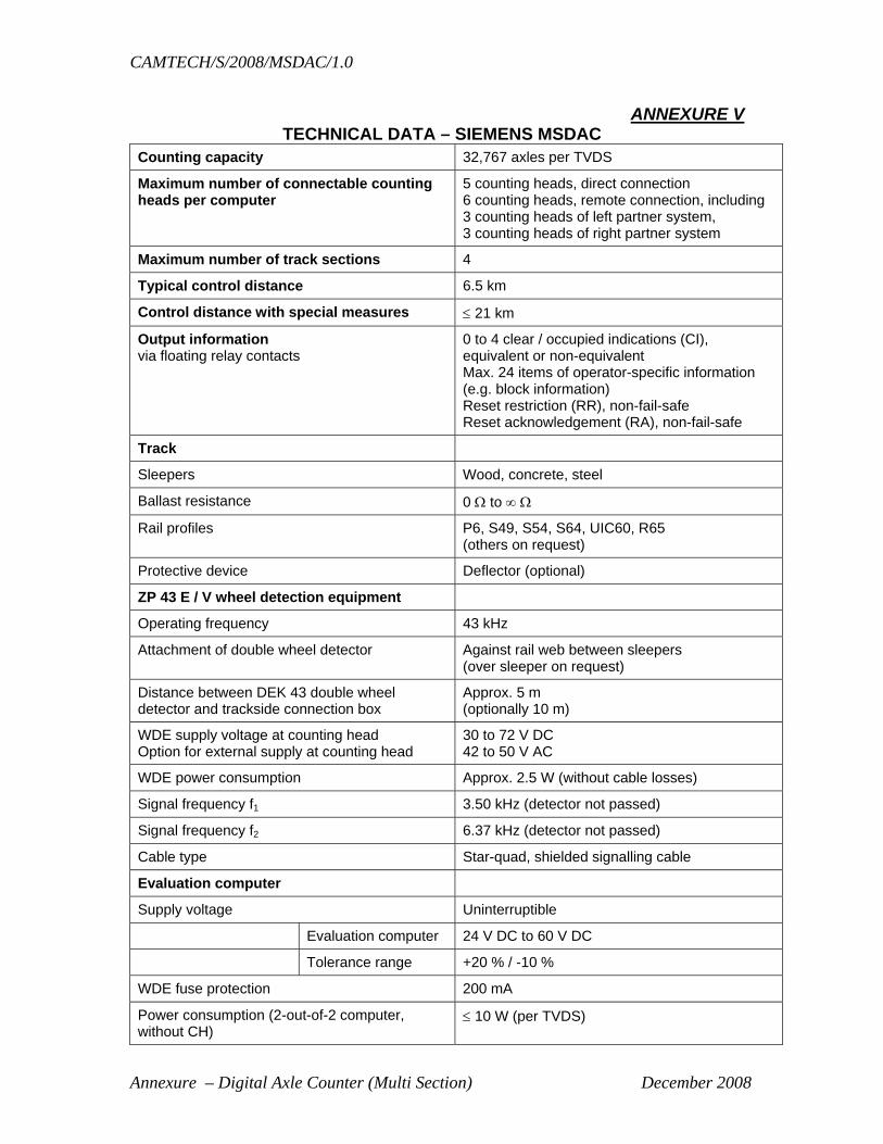
CAMTECH/S/2008/MSDAC/1.0
Annexure – Digital Axle Counter (Multi Section) December 2008
ANNEXURE V TECHNICAL DATA – SIEMENS MSDAC
Counting capacity 32,767 axles per TVDS
Maximum number of connectable counting heads per computer
5 counting heads, direct connection 6 counting heads, remote connection, including 3 counting heads of left partner system, 3 counting heads of right partner system
Maximum number of track sections 4
Typical control distance 6.5 km
Control distance with special measures ≤ 21 km
Output information via floating relay contacts
0 to 4 clear / occupied indications (CI), equivalent or non-equivalent Max. 24 items of operator-specific information (e.g. block information) Reset restriction (RR), non-fail-safe Reset acknowledgement (RA), non-fail-safe
Track
Sleepers Wood, concrete, steel
Ballast resistance 0 Ω to ∞ Ω
Rail profiles P6, S49, S54, S64, UIC60, R65 (others on request)
Protective device Deflector (optional)
ZP 43 E / V wheel detection equipment
Operating frequency 43 kHz
Attachment of double wheel detector Against rail web between sleepers (over sleeper on request)
Distance between DEK 43 double wheel detector and trackside connection box
Approx. 5 m (optionally 10 m)
WDE supply voltage at counting head Option for external supply at counting head
30 to 72 V DC 42 to 50 V AC
WDE power consumption Approx. 2.5 W (without cable losses)
Signal frequency f1 3.50 kHz (detector not passed)
Signal frequency f2 6.37 kHz (detector not passed)
Cable type Star-quad, shielded signalling cable
Evaluation computer
Supply voltage Uninterruptible
Evaluation computer 24 V DC to 60 V DC
Tolerance range +20 % / -10 %
WDE fuse protection 200 mA
Power consumption (2-out-of-2 computer, without CH)
≤ 10 W (per TVDS)
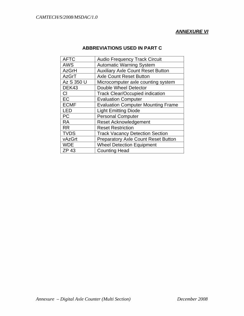
CAMTECH/S/2008/MSDAC/1.0
Annexure – Digital Axle Counter (Multi Section) December 2008
ANNEXURE VI
ABBREVIATIONS USED IN PART C
AFTC Audio Frequency Track Circuit AWS Automatic Warning System AzGrH Auxiliary Axle Count Reset Button AzGrT Axle Count Reset Button Az S 350 U Microcomputer axle counting system DEK43 Double Wheel Detector Cl Track Clear/Occupied indication EC Evaluation Computer ECMF Evaluation Computer Mounting Frame LED Light Emitting Diode PC Personal Computer RA Reset Acknowledgement RR Reset Restriction TVDS Track Vacancy Detection Section vAzGrt Preparatory Axle Count Reset Button WDE Wheel Detection Equipment ZP 43 Counting Head