block working by axle counter - indian railwayrdso.indianrailways.gov.in/works/uploads/file/handbook...
TRANSCRIPT
BLOCK WORKING ON DOUBLE LINE BY AXLE COUNTER
1.0 INTRODUCTION
In Indian Railways, Absolute Block System is in existence for double line section. Thissystem requires conventional double line block instruments. The complete arrival of train isphysically verified by receiving end Station Master (SM)/ Cabinman/ switchman/ ASM,who checks the “Last Vehicle Board” or the Tail Lamp. When it is not possible to do so, acertificate indicating that :
The train has arrived completely, andTrain is standing clear of fouling mark,
is taken from the Guard. This results in detention to the trains .
In busy section if receiving end SM fails to follow the procedure strictly, there is apossibility of block being closed even if parting has occurred in mid-section and completetrain has not arrived. Some accidents had taken place on this account. To avoid detentionsto trains and ensure safe working of trains, Axle counters are used for complete arrival oftrains and closing of block sections automatically.
The axle counter block system is operated on a continuously energized principle.
The train occupies & clear the block section automatically.
2.0 DETAILS OF EQUIPMENT
2.1 The Axle Counter Block System for a block section, comprises of the followingequipment :
EQUIPMENT QTY.INDOOR Station master’s block panel 2 Nos.
Axle counter rack 2 Nos.a) Multiplexers-
Transmitter & ReceiverB) Combiner/Converter -
Transmitter & Receiver
2 Nos.
2 Nos.
Composite relay rack 2 Nos.OUT-DOOR
Track devices alongwith junctionboxes 4 Wire/2 Wire 4 Wire type
2 Sets2 Sets
PET Quad in RE cable 1 ½

CAMTECH/99/S/AXLE/1.0 2
BLOCK WORKING BY AXLE COUNTER JULY’ 1999
2.1.1 S.M.’s Block panel
SM’s control panel is shown in the diagram. It is provided with the following:
Two lighted strips - One for Train Going To (TGT) and another for Train ComingFrom (TCF). Each strip shows:
♦ Yellow light for ‘Line Closed’ condition. ♦ Green light for TGT/TCF condition. ♦ Red light for ‘Train On Line’ (TOL) condition.
Four LED indications for the following.
♦ TGT line free - Green. ♦ TCF line free - Green ♦ TGT line occupied or block forward/back - Red. ♦ TCF line occupied or block forward/back - Red.
A Red colored ‘Train Going To’ push button .
An SM’s Key for controlling SM’s panel keeping control over operations.
Two acknowledgment push buttons with yellow light indication.
♦ ‘TGT’ “Line occupied / Line free” acknowledgment. ♦ ‘TCF’ “Line occupied / Line free” acknowledgment
A “Line Clear” Blocking Key (LCB)-meant for
SM’s BlockFig. No. 1

CAMTECH/99/S/AXLE/1.0 3
BLOCK WORKING BY AXLE COUNTER JULY’ 1999
♦ withdrawing the Line Clear already taken. ♦ preventing fresh line clear.
A bell push button for calling other end SM’s attention and to be pressed along with‘TGT’ button to take line clear or with Reset key out to withdraw line clear alreadytaken.
A Reset Cooperation Push Button and Reset Key - To be operated during failure of
the block system.
Telephone- For conversation with other end SM.
LSS indication - Last stop signal aspects proving indications i.e. ON & OFF aspectsare given.
Counter - To register number of Axle Counter resetting cases.
2.1.2 Axle counter rack
The axle counter rack (contains the evaluator, SUPR, EVR etc.) is installed in relay room.
The axle counter receives the track side signals through a quad cable from advance starterand home signal locations.
The evaluators for each direction of block working are kept at the receiving station and theaxle counter monitors the complete portion of track between the last stop signal (LSS) atTrain Sending station and block overlap (180 Mts.) in advance of the home signal at Trainreceiving station.
2.1.3 Prewired relay rack
Relay rack consists of provision for 24 plug-in type QNA1/ QNN1 relays & subracks. Tx - MUX, Rx -MUX and Combiner- Converter.
The rack alongwith axle counter is installed on a raised platform inside relay room.
Details of the connections between track device, multiplexer and axle counterevaluater are indicated in diagram.
CAMTECH/99/S/AXLE/1.0 4
BLOCK WORKING BY AXLE COUNTER JULY’ 1999
Multiplexer
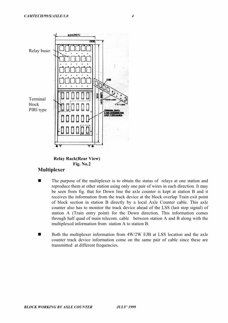
The purpose of the multiplexer is to obtain the status of relays at one station andreproduce them at other station using only one pair of wires in each direction. It maybe seen from fig. that for Down line the axle counter is kept at station B and itreceives the information from the track device at the block overlap Train exit pointof block section in station B directly by a local Axle Counter cable. This axlecounter also has to monitor the track device ahead of the LSS (last stop signal) ofstation A (Train entry point) for the Down direction. This information comesthrough half quad of main telecom. cable between station A and B along with themultiplexed information from station A to station B.
Both the multiplexer information from 4W/2W EJB at LSS location and the axlecounter track device information come on the same pair of cable since these aretransmitted at different frequencies.
Relay Rack(Rear View)Fig. No.2
Relay buses
TerminalblockPIRI type

CAMTECH/99/S/AXLE/1.0 5
BLOCK WORKING BY AXLE COUNTER JULY’ 1999
Similarly the other half quad is used for transmitting the axle counter track device atLSS location information from station B which is required by the up evaluator atstation A and also for transmitting the multiplexer information from station B tostation A. Since there are two track devices associated with each detection point,normally 2 pairs of wires are required to carry 5 KHz signals up to the evaluator. Toeconomise over pair of wires between stations, Channel B at track device at LSSlocation is converted from 5 KHz to 3.5 KHz and combined with 5 KHz at ‘A’Channel at same location for transmission at a single pair.
The multiplexer has a total capacity for handling 10 relay inputs.
The multiplexer works in TDM (Time Division Multiplexing) mode and convertsthe relays status in to digital bits 0 and 1.
It transmits them through the cable after doing frequency shift key modulationusing two frequencies of 1100 Hz/1300 Hz for one direction and 1500 Hz /1700 Hzfor other direction.
From each station seven relays are repeated from station A to station B and viceversa for Up & Dn. direction, the multiplexer has five spare inputs at each station. Inthe 16 bits of data of the multiplexer two parity check bits are used for errordetection purpose.
The multiplexer has a duplicated circuitry by way of hardware redundancy.
The maximum cable attenuation between transmitter and receiver of themultiplexer could be 20 dB.
It works on 24 V +20 %
-10 % The current consumption is 3 Amp. including 24 nos. ofPlug in Relays in Rack .
Multiplexer & Prewired Relay RackFig. No. 3
CAMTECH/99/S/AXLE/1.0 6
BLOCK WORKING BY AXLE COUNTER JULY’ 1999
2.1.5 4 Wire / 2 Wire EJB design feature
It consist of four modules. It is installed at Advanced starter for detecting the trainentry in to the section.
The 4 wire/2 wire converter has been designed to economize the requirement ofcable pairs in transmitting information from EJB (Electronic Junction Box) toevaluator.
This is an extra card to be fitted in conventional EJB and works on EJB’s powersupply.
It converts frequency of Channel at track device channel 5 KHz frequency to 3.5KHz.
It consists of three conventional modules namely :
♦ OSC. Card ♦ REC1 Card ♦ REC2 Card and a 4W/2W convertor card as 4th module.
Since, A and B outputs are at different frequencies, it is possible to transmit theoutputs of two receiver coils to the evaluator through one pair of cable (1/2 quad)only.
Combiner
It is a part of 2nd card in combiner converter.
It combines the FSK output of Mux Transmitter & composite signal from EJB andlaunches it on 1120 side of VFT Transformer for tranmission to other station.
Converter
Likewise at the other end of the cable a 2 wire/6 wire equipment is used which againreproduces the original two receiver outputs of 5 KHz. from the combined 5 KHz -3.5 KHz. signal coming through 2 wire circuit.
The 4 wire output of the 2 wire/6 wire equipment at the receiving end is connectedto the evaluator.
It demuxes the composite signal, received from other station on VI Transformer into 3 signals.
♦ 5 KHz A Channel for Evaluation.

CAMTECH/99/S/AXLE/1.0 7
BLOCK WORKING BY AXLE COUNTER JULY’ 1999
♦ 3.5 KHz B Channel later on converts it to 5 KHz for evalator throughfrequency 3.5 KHz.
♦ FSK signal for receiver 1100/1300 Hz or 1500/1700 Hz.
2.1.6 Track devices
Track devices are installed at Home signal & Advanced starter.
Track devices detect the passage wheels/axles passing it.
2.1.7 Cable
The frequencies 1100/1300 Hz and 1500/1700 Hz are different from the frequenciesused for axle counters and therefore the multiplexer information as well as the axlecounter track device (output of 4W/2W converter unit) information from station Ato station B can go on one pair i.e. ½ PET Quad of main telecommunication. pair onthe PET quad. Similarly the multiplexer information and axle counter track deviceinformation from station B to station A can go on another ½ PET quad of the maintelecom. cable.
The data is transmitted through the cable at the speed of 110 BPS.
The bell code transmission is by transmission of 150-190 Hz. AC signal rectified &fed to Bell Relay, Telephone transmission takes place on one pair of wire.
3.0 OPERATION OF THE SYSTEM
3.1 In the conventional double line block instrument all the operations are performedby the receiving end station master. But in Axle Counter Block System, all operations areperformed by sending end station master except for withdrawal /cancellation of line clear.
When it is intended to dispatch a train to the next station, the SM of the sending stationpushes the TGT (Train Going To) button on his panel. If all the conditions for the receptionof the train are satisfied at the receiving station, an indication of “Train Going To” (Greenlight) appears on the SM’s panel at the sending station. Simultaneously an indication ofTCF (Train Coming From) appears on the panel at receiving end station.
TGT indication on the panel enables the SM at the sending end to clear the Advancedstarter at his station.
When the train enters in the block section, the green TGT indication disappears and a redindication of TOL (Train On Line) appears automatically on the SM`s panels at sending endand receiving end, Green TCF indication disappears at receiving end. In addition buzzersring at both stations to draw the attention of the station masters at both stations.
CAMTECH/99/S/AXLE/1.0 8
BLOCK WORKING BY AXLE COUNTER JULY’ 1999
Information of departure of train into block section is given by sending end SM toreceiving end SM on phone.
The SM at the receiving station clears the Home signal and receives the train.
Line closed (Yellow) indication appears automatically on the SM’s panel at both Station,on complete arrival of Train.
3.2 Cancellation
Where a line clear has been obtained and it is afterwards found that the train to which itreferred, has to be detained owing to any reason, the following procedure must be adopted:-
■ If LSS ( last stop signal) is not taken off SM should not clear the LSS.
■ If LSS is already taken off, it must be put back to “ON ” and SM should inform thedriver of the train for which the LSS was taken off, regarding cancellation of theline clear obtained for the said train as per SR 3.36 (5) (ii).
For cancelling the “ line clear ” the following procedure must be adopted.
Sending end station gives “ call attention ” to receiving end SM and informs that thetrain for which “Line Clear” has been obtained is being detained and the “LineClear” is to be canceled. In support of this he gives a private number.
Receiving end SM acknowledges and give consent by giving a private number. Also
takes out the LCB Key and simultaneously presses Bell push button with SM`s key“IN”.
At receiving end “Train Coming From” green indication disappears & “Line
Closed” white indication appears on the Block panel. LCB Key is inserted andturned.
At sending end, “Train Going TO” green indication disappears & “Line Closed”
white indication appears on the Block panel.
NOTE : Next train can now be sent following the regular procedure & as per station workingorder.
3.3 Reset
It may be required to reset the Axle counter in very rare cases of extra ordinary conditions.It is necessary to take all precautions to verify the block section is free of vehicles beforethe reset operation is carried out in the system. The procedure is given below in clauses3.3.1 and 3.3.2 for reset operation taking in to account of the working rules of Railway.

CAMTECH/99/S/AXLE/1.0 9
BLOCK WORKING BY AXLE COUNTER JULY’ 1999
3.3.1 Reset push button : (Reset co-operation from sending end)
The receiving end SM requests the reset co-operation for resetting of axle counter after hisverification of the last train passed in the section. The sending end SM presses the resetcooperation push button on the panel. This will actuate one of the Multiplexer Relays on thereceiving end and is indicated by yellow LED glow near reset counter. This permits thereceiving end SM to reset the Axle counter inserting Axle Counter reset key & pressing itfor a moment.
3.3.2 Resetting of the Axle Counter : (Receiving end)
I . During Installation and Commissioning
The reset is applied in Axle counter by pressing the key actuator push button after the resetcooperation is obtained as given in para 3.3.1. The section verification is not required andthe reset is applied in a normal course.
II. There can be following failures of block system :
Case I :
When the train has been received at the receiving station, but the “Line occupied” redindication remains on the panel. In such cases the receiving end SM verifies the clearanceof block section by checking the last vehicle of the train at his station and initiates thefollowing action-
If last vehicle has arrived :- The receiving end SM requests the Reset cooperationfrom station in rear A station as per clause 3.3.1 after obtaining the reset cooperationby means of yellow LED indication available on panel. As soon as the reset relay inAxle counter is actuated the Axle Counter becomes Resetted when the key actuatoris released in the SM`s panel, the counter increments by one count only on sucessfulreset of Axle Counter. The sending end reset cooperation is also to be withdrawnlater. After the above procedure the Axle Counter gets resetted and line freeindication of block section is available on the panel. The line clear for next trainmovement may be taken in a normal manner without the observation of cautionorder.
When Last Vehicle could not be checked by receiving end SM it may be verifiedfrom station ahead, the receiving end SM initiates and follows the procedure forreset of Axle Counter given above. But the next train is allowed on caution order asper the Railway Working Rules.
Case 2 : Axle Counter fails without any train movement in the block section
The following may be the reasons :
♦ Tx/Rx coil broken/damaged on track side.

CAMTECH/99/S/AXLE/1.0 10
BLOCK WORKING BY AXLE COUNTER JULY’ 1999
♦ Failure of cards in junction box & Axle Counter Evaluator. ♦ Failure of Advance/Home track circuits.
In such cases of failures the ESM is required to attend the failure. After rectification offault, the SM of receiving end follows the resetting procedure and the Axle Counter isresetted. The line clear for the next train is taken and train is sent on caution order.
4.0 STATUS OF RELAYS DURING TRAIN WORKING
4.1 The following chart gives the position of relays at both stations for getting ‘Lineclosed’ condition on both ‘up’ and ‘down’ lines of the block section.
DESPATCH RELAYS ATSENDING STATION
RECEPTION RELAYS ATRECEIVING STATION
ADV TPR AZTR SR BCR AMR ADV TPPR
BPR AZTPR HOME TPR TGTR AMR TCFPR TCFR DR TGTPR TOLR TOLR BCPR ZR
BSMR ASMR AXPR
4.2 The position of relays for getting ‘Train Going To’ and ‘Train Coming From’ on
sending and receiving stations SM’s panel respectively.
Assume the names of block stations as ‘A’ and ‘B’ and SM of the sending stationtakes ‘line clear’ for despatching a train from ‘A’ to ‘B’.
S.M`s key should be turned to ‘ON’ position at station ‘A’ and LCB key should beturned to ‘ON’ position at station ‘B’
STATION -ADESPATCH RELAYS
STATUS
STATION - BRECEPTION RELAYS
STATUS
S.M’s key should be in ‘ON’position
LCB key should be in ‘ON’position
ADV TPR AZTR SR BCR AMR ADV TPPR
BPR AZTPR HOME TPR
CAMTECH/99/S/AXLE/1.0 11
BLOCK WORKING BY AXLE COUNTER JULY’ 1999
TGTR AMR TCFPR TCFR DR TGTPR TOLR TOLR BCPR ZR
BSMR ASMR AXPR
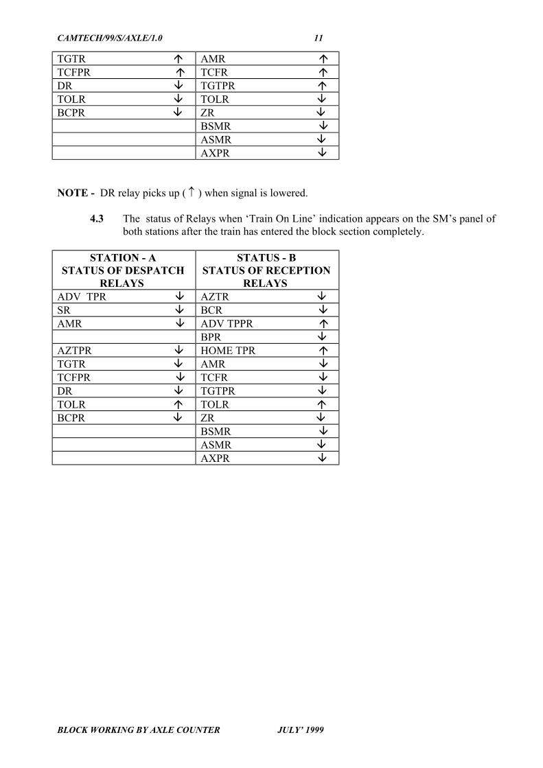
NOTE - DR relay picks up ( ↑ ) when signal is lowered.
4.3 The status of Relays when ‘Train On Line’ indication appears on the SM’s panel ofboth stations after the train has entered the block section completely.
STATION - ASTATUS OF DESPATCH
RELAYS
STATUS - BSTATUS OF RECEPTION
RELAYS ADV TPR AZTR SR BCR AMR ADV TPPR
BPR AZTPR HOME TPR TGTR AMR TCFPR TCFR DR TGTPR TOLR TOLR BCPR ZR
BSMR ASMR AXPR

CAMTECH/99/S/AXLE/1.0 12
BLOCK WORKING BY AXLE COUNTER JULY’ 1999
5.0 INSTALLATION
Manual supplied with Axle Counter should be referred.
The SM’s panel is to be installed in SM’s/ ASM’s/ cabin in such a way so that themarked layouts of TGT/ TCF provided on the SM’s panel is in correspondence withthe actual layout.
The SM’s panel should be so installed to have sufficient space for opening the backdoor for connecting the MS couplers and for maintaining the circuits inside theSM`s panel.
Open the back door and take out the open ends of 24 pin and 19 pin MS couplercables, through the respective holes provided at the bottom of SM’s panel. The twoM.S.Coupler plugs are to be tightened by rotating the couplers in clockwisedirection
The SM’s key and L.C.B. key have to be inserted in their respective positions andturned to ‘ON’ position for normal operation of block. The reset key is to be insertedand kept in its position.
The axle counter rack is installed in relay room with in 100 Mts. from SM’s panelinstallation.
The axle counter rack may be installed on a raised platform. EVR and SUPR areplaced inside axle counter relay rack and wired with 16/0.2 PVC wires.
The track side electronic junction box and respective track devices are installed nearadvanced starter and home signals on a minimum 3 rail length of closed trackcircuit.
The track devices are located at 33 Mts. from the start of the track circuit & 6 Mts.,from end of track circuit in the direction of train.
Relay rack and axle counter rack are installed side by side.
The relay rack and axle counter should have clear space of 650 MM. on front, backand any side to open the door for installation and maintenance.
The rack is having provisional space for 24 plug in type QNA1/QNN1 relays. Theplug in relays supplied are identified by the relay name and each is to be inserted into its respective socket and clamped with relay clamp.
Combiner/converter are installed at the bottom most space of the rack. Tighten thetwo 10 pin MS Couplers (plug) to the respective receptacles of combiner/convertersub system from the back side of the rack.
The Rx-Mux is to be inserted in the middle of the rack. Install and tighten the two14 pin M.S.Coupler and one 7 pin MS Coupler into their respective receptacles.
CAMTECH/99/S/AXLE/1.0 13
BLOCK WORKING BY AXLE COUNTER JULY’ 1999
The Tx-Mux sub system is to be installed above the Rx-Mux at the top slot. The Tx-Mux MS couplers are of 14 pin and 10 pin type and have to be tightened to theirrespective receptacles.
The cable coming from SM’s panel, axle counter rack, battery banks, advance andhome lever circuit controller. Connections have to be terminated as per drawingsupplied by the Manufacturer.
Battery bank (+ 24 V) supply connections are made only at the final stage i.e. aftercompleting and checking of all wiring. “Power on” switches of Tx-Mux, Rx- Muxmust be kept in ‘off’ position and switched ‘ON’ only after ensuring the correctnessof wiring.
Cable coming from other station is directly terminated in relay rack as per drawing
supplied by manufacturer.
Axle Counter cable shall only be earthed at Evaluator end/combiner as the case maybe, rest of the cable shall not be earthed at any point, wherever cable pair is totapped out shield and armour of cable shall be made through insulated from eachother.
The track relay used shall be Q series plug in type - QT/QTA/QBAT followed by
QN1/QNA1/QSPA1 need not be provided for trolley protection in block section.
6.0 EARTHING
■ All equipment are to be earthed properly as per instructions given byManufacturer.
■ Earth resistance should not be more than 3 ohms.
7.0 COMMISSIONING
To be commissioned as per Manufacturer’s instructions.
8.0 MAINTENANCE
8.1 Battery bank and battery charger (weekly)
Check battery bank i.e. batteries electrolyte level, specific gravity and voltage.
For efficient battery maintenance refer Hand book on lead acid secondary cell issuedby IRCAMTECH, Gwalior.
Inspect the charging equipment, measure charging current and ensure that it isadequate more than load current about 25%.
8.2 Relay rack (Fortnightly)
Ensure that the retainer clips are holding the relays properly.

CAMTECH/99/S/AXLE/1.0 14
BLOCK WORKING BY AXLE COUNTER JULY’ 1999
Check proper sequential functioning of the relays as per the train movement.
Check DC voltage to the relay rack, it should be with in specified limit i.e. 24V +20% - 10%.
Check the tightness and proper fitting of the fuses provided at the rear of the relayrack.
8.3 Transmitter Multiplexer (Fortnightly)
Ensure that all PCB modules are properly inserted and confirm that the captivescrews provided in the front plate are tight.
Ensure that the MS couplers provided at the rear plate are tight.
Ensure 10.8 +0.2 V DC at the socket provided on the front plate 8th module.
Check the FSK signal output at the FSK socket provided in 3rd module. It should bein the range of 1.5 +0.2V. If necessary adjust the level with the potentiometerprovided on the module. The locking nut of the potentiometer should then betightened.
On the same module a high/low switch will be available in same equipment high for
block section length more than 5 Kms. & low for other wise.
8.4 Receiver Multiplexer (Fortnightly)
Ensure that all PCB modules are properly inserted and the captive screws are tight.
Ensure that the MS couplers provided at the rear plate are tight.
Measure the DC regulated voltage at the 10 V sockets provided in 7th module. Itshould be 10.8 +0.2V.
With a high impedance multimeter check the FSK signal output at the socket in 7th
module. It should be 1.5V + 0.2V rms. (AC). If necessary adjust with thepotentiometer. The locking nut of the potentiometer should be tightened afteradjustment.
CAMTECH/99/S/AXLE/1.0 15
BLOCK WORKING BY AXLE COUNTER JULY’ 1999
8.5 Combiner/Converter (fortnightly)
Ensure that all PCB modules are properly inserted and the captive screws are tight.
Ensure that the couplers provided at the rear plate are tight.
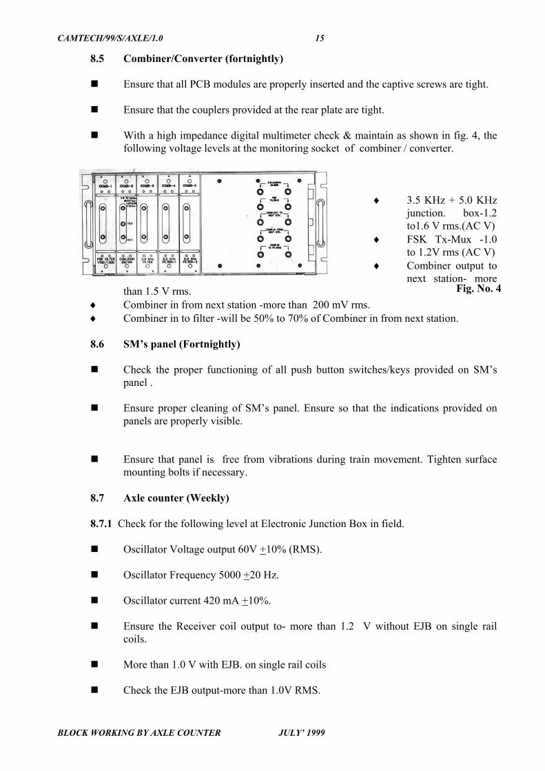
With a high impedance digital multimeter check & maintain as shown in fig. 4, thefollowing voltage levels at the monitoring socket of combiner / converter.
♦ 3.5 KHz + 5.0 KHzjunction. box-1.2to1.6 V rms.(AC V)
♦ FSK Tx-Mux -1.0to 1.2V rms (AC V)
♦ Combiner output tonext station- more
than 1.5 V rms.♦ Combiner in from next station -more than 200 mV rms.♦ Combiner in to filter -will be 50% to 70% of Combiner in from next station.
8.6 SM’s panel (Fortnightly)
Check the proper functioning of all push button switches/keys provided on SM’spanel .
Ensure proper cleaning of SM’s panel. Ensure so that the indications provided onpanels are properly visible.
Ensure that panel is free from vibrations during train movement. Tighten surfacemounting bolts if necessary.
8.7 Axle counter (Weekly)
8.7.1 Check for the following level at Electronic Junction Box in field.
Oscillator Voltage output 60V +10% (RMS).
Oscillator Frequency 5000 +20 Hz.
Oscillator current 420 mA +10%.
Ensure the Receiver coil output to- more than 1.2 V without EJB on single railcoils.
More than 1.0 V with EJB. on single rail coils
Check the EJB output-more than 1.0V RMS.
Fig. No. 4
CAMTECH/99/S/AXLE/1.0 16
BLOCK WORKING BY AXLE COUNTER JULY’ 1999
8.7.2 Evaluator
Check at Evaluator check all PCB cards are properly inserted and the captivescrews are tight.
Ensure that the MS couplers provided at the rear side are tight.
Ensure that all channel’s individual levels at card no.1 are 05 mV + 5 .
Ensure that EV / SUP relay voltage is more than 10 V DC of universal axle counter.
Ensure that BY 127 diode is fixed across the coil of EV/SUP Relays.
9.0 DO’s AND DON’Ts
9.1 DO’s
Tighten all the couplers properly in the combiner/converter and Mux/ Receiver/Mux-Transmitter.
Insert fuse holders provided in the relay rack (F1 to F4) properly.
Insert all the cards properly in the mother board before replacement of new cards,since any loose fitting of these cards can also lead to error condition.
Avoid rough handling of relays during insertion and removal.
Check proper earthing.
9.2 DON’Ts
Insert or remove cards from Mux-Transmitter or Mux-receiver when the ‘PowerON’ switch is in ‘ON’ position.
Operate bell plunger push button for exchanging block codes when telephonicconversation is taking place.
Apply oil/grease on push buttons.
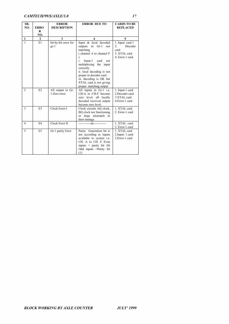
FAULT CHART FOR MUX TRANSMITTER ERROR CARD 1
CAMTECH/99/S/AXLE/1.0 17
BLOCK WORKING BY AXLE COUNTER JULY’ 1999
SR.NO. ERRO
R NO.
ERRORDESCRIPTION
ERROR DUE TO CARDS TO BEREPLACED
1 2 3 4 51 E1 bit-by-bit error for
gr-1 Input & local decodedoutputs in Gr-1 notmatching( channel A to channel F)i. Input-1 card notmultiplexing the inputcorrectly.ii. local decoding is notproper in decoder card.iii. decoding is OK butXTAL card is not givingproper matching output
1. Input- card 12. Decodercard3. XTAL card4. Error-1 card
2 E2 All output in Gr-1-Zero error
All inputs in Gr-1 i.e.CH-A to CH-F becomezero level. all locallydecoded received outputbecome zero level.
1. Input-1 card2.Decoder card3.XTAL card4.Error-1 card
3 E3 Clock Error-I Clock circuits AQ clock,BQ clock not functioningor large mismatch intheir timings.
1. XTAL card2. Error-1 card
4 E4 Clock Error II ------------do------------ 1. XTAL card2. Error-1 card
5 E5 Gr-1 parity Error Parity Generation bit isnot according to inputsavailable to system i.e.CH. A to CH. F Eveninputs = parity bit (0)Odd inputs =Parity bit(1)
1. XTAL card2.Input- 1 card3.Error-1 card
CAMTECH/99/S/AXLE/1.0 18
BLOCK WORKING BY AXLE COUNTER JULY’ 1999
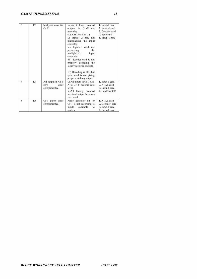
6 E6 bit-by-bit error forGr.II
Inputs & local decodedoutputs in Gr.-II notmatching(i.e. CH-G to CH-L )i.) Inputs -2 card notmultiplexing the inputcorrectly.ii.) Inputs-1 card notprocessing themultiplexed inputcorrectly.iii.) decoder card is notproperly decoding thelocally received outputs.
iv.) Decoding is OK, butsync. card is not givingproper matching output.
1. Input-2 card2. Input -1 card3. Decoder card4. Sync card5. Error -1 card
7 E7 All output in Gr-1zero errorcomplimented
i.) All inputs in Gr-1 CH-A to CH-F become zerolevel.ii.)All locally decodedreceived output becomeszero level.
1. Input-1 card 2. XTAL card3. Error-1 card4. Card 2 of CC
8 E8 Gr-1 parity errorcomplimented
Parity generator bit forGr-1 is not according toinputs available tosystem
1. XTAL card2. Decoder card3. Input-1 card 4. Error-1 card

CAMTECH/99/S/AXLE/1.0 19
BLOCK WORKING BY AXLE COUNTER JULY’ 1999
FAULT CHART FOR MUX TRANSMITTER ERROR CARD-2
SR.NO.
ERROR NO.
ERROR DESCRIP-TION
ERROR DUETO
CARDS TO BEREPLACED IN
SEQUENCEUNTILL THEERROR GETS
REPLACED1 E9 Gr-1 input all zero error
complimented.All inputs in Gr-1 CH-A to CH-Fbecome zerolevel.
1.Input -1 card 2. Error-2 card
2 E10 Gr-2 input all zero errorcomplimented.
All inputs in Gr-2 ch-G to ch-Lbecome zerolevel.
1.Input-1 card2. Error-2 card
3 E11 Gr-2 parity errorcomplimented.
Parity generationbit for Gr-2 isnot according toinputs availableto system.
1. Sync card2.Input-2 card3.Error-2 card4.Decoder card
4 E 12 All out[put in Gr-2 zeroerror complimented.
All inputs in Gr-2 ch-G to ch-Lbecome zerolevel.
1.Input-2 card2.Decoder card3.Sync .card4.Error-2 card
5 E13 Gr-2 parity error Parity generationbit is notaccording toinputs availableto system i.e. ch-G to ch-L Eveninput =parity bit(O) odd input =parity bit (1)
1. Sync. card2. Input-2 card3. Error-2 card
6 E14 All outputs in Gr-2 zeroerror.
All inputs in Gr-2 i.e. ch G to chL become zerolevel
1. Sync. card2. Decoder card3. Input-2 card4. Error-2 card5. Input-1 card
7 E 15 Sync. clock Error-1complimented
Clock circuitsAQS,BQS notfunctioning orlarge mismatchin their timings.
1. XTAL- card2. Sync.-card3. Error-2 card
8 E 16 Sync. clock Error -2 complimented.
Clock circuitsAQS, BQS notfunctioning orlarge mismatchin their timings
1. XTAL- card2. Sync.-card3. Error-2 card
9 E 15 Sync. clock Error-1complimented.
Clock circuitsAQS, BQS notfunctioning orlarge mismatchin their timings.
1. XTAL- card2. Sync.-card3. Error-2 card
CAMTECH/99/S/AXLE/1.0 20
BLOCK WORKING BY AXLE COUNTER JULY’ 1999
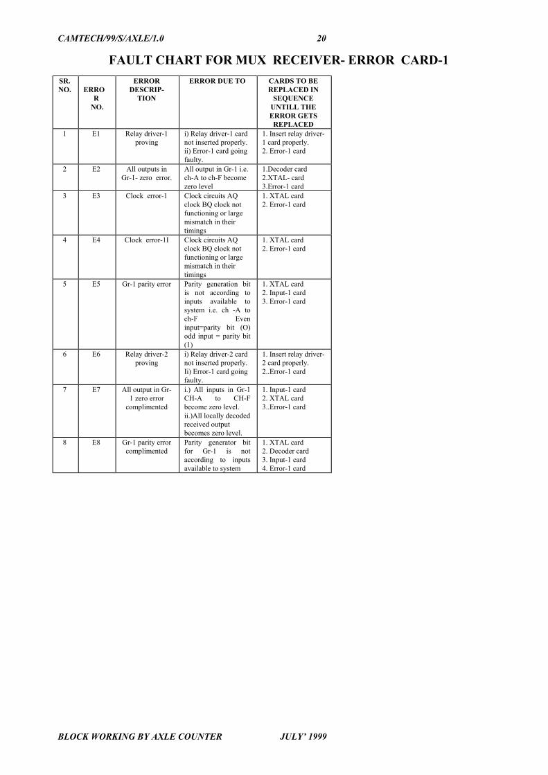
FAULT CHART FOR MUX RECEIVER- ERROR CARD-1SR.NO. ERRO
R NO.
ERRORDESCRIP-
TION
ERROR DUE TO CARDS TO BEREPLACED IN
SEQUENCEUNTILL THEERROR GETS
REPLACED1 E1 Relay driver-1
provingi) Relay driver-1 cardnot inserted properly.ii) Error-1 card goingfaulty.
1. Insert relay driver-1 card properly.2. Error-1 card
2 E2 All outputs inGr-1- zero error.
All output in Gr-1 i.e.ch-A to ch-F becomezero level
1.Decoder card2.XTAL- card3.Error-1 card
3 E3 Clock error-1 Clock circuits AQclock BQ clock notfunctioning or largemismatch in theirtimings
1. XTAL card2. Error-1 card
4 E4 Clock error-1I Clock circuits AQclock BQ clock notfunctioning or largemismatch in theirtimings
1. XTAL card2. Error-1 card
5 E5 Gr-1 parity error Parity generation bitis not according toinputs available tosystem i.e. ch -A toch-F Eveninput=parity bit (O)odd input = parity bit(1)
1. XTAL card2. Input-1 card3. Error-1 card
6 E6 Relay driver-2proving
i) Relay driver-2 cardnot inserted properly.Ii) Error-1 card goingfaulty.
1. Insert relay driver-2 card properly.2..Error-1 card
7 E7 All output in Gr-1 zero error
complimented
i.) All inputs in Gr-1CH-A to CH-Fbecome zero level.ii.)All locally decodedreceived outputbecomes zero level.
1. Input-1 card 2. XTAL card3..Error-1 card
8 E8 Gr-1 parity errorcomplimented
Parity generator bitfor Gr-1 is notaccording to inputsavailable to system
1. XTAL card2. Decoder card3. Input-1 card 4. Error-1 card

CAMTECH/99/S/AXLE/1.0 21
BLOCK WORKING BY AXLE COUNTER JULY’ 1999
FAULT CHART FOR MUX RECEIVER ERROR CARD-2
SR.NO. ERRO
R NO.
ERRORDESCRIP-
TION
ERROR DUE TO CARDS TO BEREPLACED IN
SEQUENCEUNTILL THEERROR GETS
REPLACED 1 E9 Relay driver -3
provingRelay driver-3 cardnot inserted properly.
1. Insert relay driver-3card properly.2. Relay driver -3 card3. Error -2 card
2 E 10
Relay driver -4proving.
Relay driver-4 cardnot inserted properly.
1. Insert relay driver-4card properly.2.Relay driver -4 card3..Error -2 card
3 E11
Gr-2 parityerrorcomplimented.
Parity generation bitfor Gr-2 is notaccording to inputsavailable to system.
1. Sync. card2..Error-2 card3. Decoder card
4 E12
All outputs inGr-2 zero errorcomplimented.
All inputs in Gr-2 i.e.ch G to ch L becomezero level
1. Sync. card2. Decoder card3. Error-2 card4.Check quad cableconnection & loss
5 E13
Gr-2 parityerror
Parity generation bitis not according toinputs available tosystem i.e. ch-G toch-L Eveninput=parity bit (O)odd input = parity bit(1)
1. Sync. card2.Error-2 card
6 E14
All output inGr-2 zero error
All inputs in Gr-2 i.e.ch G to ch L becomezero level
1. Sync. card2. Decoder card3. Input-2 card4. Error-2 card5. Input-1 card
7 E 15
Sync.clockError-1complimented.
Clock circuits AQS,BQS not functioningor large mismatch intheir timings.
1. XTAL- card2. Sync.-card3. Error-2 card
8 E 16
Sync. clock Error -2complimented.
Clock circuits AQS,BQS not functioningor large mismatch intheir timings
1. XTAL- card2. Sync.-card3. Error-2 card