axle counter
TRANSCRIPT

AXLECOUNTER 1
TEACHING NOTES
ON
AXLE COUNTER
&
IBS
SIGNAL & TELECOMMUNICATION TRAINING CENTRE, BYCULLA, MUMBAI
(ISO 9001-2000 CERTIFIED)

AXLECOUNTER 2
CONTENTS PAGE NO.
1. INTRODUCTION 03
2. OUTDOOR & INDOOR EQUIPMENTS 03
3. BASIC FUNCTION, INSTALLATION PROCEDURE 04
4. CABLE CONNECTIONS 05
5. POWER SUPPLY, INITIAL ADJUSTMENTS 06
6. STAGGERING 07
7. TESTING OF THE SYSTEM 08
8. TROUBLE SHOOTING CHART 09
9. TROUBLE SHOOTING 10
10.ISOLATION OF DEFFECTIVE CARDS 13
11.UNIVERSAL AXLE COUNTER 18
12.INTERMEDIATE BLOCK SIGNAL 19
13.USE OF A/COUNTER FOR I B S 20
14.DESCRIPTION OF RELAYS AND CIRCUITRY 22
15.POWER SUPPLY ARRANGEMENT FOR IBS 23

AXLECOUNTER 3
AXLE COUNTER
INTRODUCTION:
Electronic axle counting system is used in place of conventional track circuits for monitoring track
section. In this system, number of axles entering a specified portion of the track at one end and leaving
the track circuit at the other end is counted electrically/electronically. And if the IN COUNT and OUT
COUNT tallies, the section is deemed to be clear of presence of vehicles.
Axle counters are used for:
� Plain track [Working track] (maximum length)
� Points and crossings
� Long bridges
� I B Signalling
Components of the system:
The main components of the system are:
� Outdoor equipment [detection points in the track area]
� Information transmission equipment[cables]
� Indoor equipment [evaluation, indication & resetting]
Outdoor equipment:
a) Rail inductors: It consists of an electronic rail inductor set and electronic junction box. The rail
inductor set consists of Transmitter & Receiver coils. The rail inductors are fixed to the base of
the rail by steel clamps, while the transmitter housing is fixed on the base clamp on the outer side
of the rail and the receiver housing is fixed on the inner side of the rail and staggered by 150mm
to 200mm relative to each other from one set of electronic indicator. See Figure.
b) Electronic Junction Box: The electronic junction box consists of the power supply generator-
amplifier and receiver circuits required for the operation of Rail inductors and information
transmission. The transmitter coils are connected in series to the oscillator. The receiving
amplifiers are connected independently to the respective RX coils. See figure:
c) Trolley protection track circuits: A short length of track circuit is used along with field nits so as
to prevent insulated push trolleys from actuating the axle counters to prevent failures caused by
indiscriminate use of push trolleys. The axle counter will not count unless the track circuit is
shunted. The shunting of track circuit will not take place as push trolleys are insulated.
Information Transmission Equipment:
The transmission equipment forwards the information from the detection points to the indoor equipment.
It usually consists of a cable with communication characteristics for the operating mode TWOWIRE
transmission (ONE WIRE pair) and for operating mode FOUR WIRE transmission (TWO WIRE pair)
of cables is necessary. The transmission equipment is also used for the supply voltage to the detection
points. The maximum possible distance between the detection points and the evaluation equipment
depends upon the loop resistance and the attenuation of the connection lines. The maximum permissible
line loss on the cable is18db.
Indoor equipment:
The indoor equipment evaluates the signal received from the detection points. Viz:
1. It counts the axle pulses.
2. Tests the outdoor equipment for proper functioning.
3. Collects the indications of several detection points.
4. Forms a track clear or track occupied information.
5. Transmits this information to the interlocking equipment.

AXLECOUNTER 4
The evaluator is made of plug-in printed circuit cards. Both the indoor and outdoor equipments are fed
from a battery via a power pack. The out put from this equipment is obtained through two line relays,
which are used to indicate the track occupied condition and to control signal aspects.
:
SM’s Re-setting Unit:
In the event of failure of the system after passage of a train due to miscount or any other failure, the
system is required to be re-set. The resetting of the system is to be initiated only after personally
verifying of the axle section. Re-set unit facilitates remote control of the unit circuit.
The unit consists of a key actuated press switch, visual indicators and a counter. The push can be
activated only after a key is inserted and the switch is unlocked. The key cab is extracted from the
switch only after the push button is normalized. The reset switch when pressed energizes the reset relay
and works in conjunction with a counter.
Basic Function:
The detection points are fed with the electronic signals of 5KHZ generated by the trackside electronic
equipment. The arrangement and shape of transmitter and receiver coils are such that two magnetic flux
paths are generated in the vicinity of the rail. These two magnetic fluxes transverse the receiver coils in
the opposite direction.
Reluctance of the magnetic paths of these two fluxes is different under normal condition when no wheel
is passing on the track devices. The flux 1 is quite large compared to the flux 2 and the resultant flux
induces voltage in the receiver coil. When the wheel passes over the track transducers, the screening
effect of the wheel flange causes a reduction of flux to a value nearly equal in magnitude to that of
flux2. These two fluxes almost cancel each other and the induced voltage in the receiver coil falls to
negligible value. This forms a dip. These signals after amplification are fed through the transmission
line to the indoor equipment, which processes and evaluates the receiver signals.
The four amplitude-modulated sign wave signals A, B, C & D channels are connected to a digital pulses
and operate the logic counters and other supervision circuits in the evaluator. The evaluator relay is
energized only when the counts stored in the IN counter and the OUT counter are equal. A second relay
is controlled by all supervisory functions and it is energized when these functions indicate that the
equipment has been functioning normally. The signal aspects are controlled by both the relays in series.
INSTALLATION PROCEDURES:
Track Detection Units:
1. The track detection units should be installed on a closed track circuit extending to a minimum of
3 rail lengths on double line and 5 rail lengths on single line.
2. To accommodate the base clamps, there should be a clear space of 600mm between two sleepers.
Either side of the sleepers should be packed well.
3. The base clamps should be fixed minimum 6 sleepers away from the nearest rail joint. The rail
inductors should not be fixed under any circumstances between sleeper carrying rail joints.
4. On electrified sections, a minimum distance of 20meters should be maintained between the rail
inductors and the nearest block joint in case of double rail track circuits.
5. The distance between two rail inductors of different axle counting circuits should be at least 5
meters so as to avoid mutual induction.
6. The clamps should be fitted one on each rail, the rail clamps should be fully tightened and locked
by means of lock washers to prevent any movement relative to the rail during the passage of a
train.
7. Transmitting coil assembly should be fixed on outer side of the rail. The clamp holding the
transmitter housing should butt against the rail feet of the rail. A nylon-packing piece of
appropriate thickness should be placed between the clamp and the base plate.
8. The receiver coil assembly should be fixed on the inner side of the rail. Gap between the
receiver housing and the rail web should be about 3mm for 90lhs, 12mm for 52Kg and 18mm for
62Kg. Nylon packing of the same thickness should be used below the receiver housing.

AXLECOUNTER 5
9. It should be ensured that the rail is not badly worn out.
10. Care should be taken to ensure the TX coil assembly and RX coil assembly are fixed parallel to
each other on the same centre line.
11. It should be ensured that the staggering between the rail inductors fixed to the two rails is so
adjusted between 150mm-200mm [preferably 175mm].
12. Protectors should be placed in the sleeper space next to the track fittings, 300mm away from the
centre of TX / RX fittings. Protectors should be maintained on both sides of the fittings on
single line and on double line.
Track Side ‘EJ’ Box:
1. The location, which houses receiver amplifier, should be placed at a level well above the
flooding level of the area.
2. This equipment should be housed in a location box, but close to the detection point so that
one length of cable should not exceed 15meters.
3. The cables for transmitter coils and receiver coils should be laid in different GI pipes at a
minimum separation of 300mm.
4. The two transmitter coils are to be connected in series to the oscillator. The receiving
amplifiers are to be connected independently to the respective receiving coils.
5. The incoming cables from the rail inductors and rail evaluator may be terminated first on a
cable distribution board. Wires from oscillators and receiver amplifier should also be
brought and terminated on the same distribution board.
CAUTION: The cable carrying oscillator output should not be cut because it is a part of tuned
circuit of 5KHz. If it is cut, then the 5KHz frequency will deviate the specified limits.
Cable Connections: 1. From rail inductor to EJ Box multi-stand flexible cable conductor twin twisted core PVC
insulated and PVC sheathed (extra soft grade) should be used.
2. The output of receiver amplifier is to be fed to the evaluator through proper cable
connections.
3. In non-RE Area, 9mm diameter conductor twin twisted or star quad communication cable
is to be used. (Impedance at 5KHz is 200 ohms approximately.)
4. In RE Area, PVC insulated star quad communication cable to RE specification should be
used (Impedance at 5KHz is 200 ohms approximately.)
5. When the distance between the evaluator and check device does not exceed 2 KMS,
6 ½ db (0.51 mm) twin twisted or star quad communication cable is to be used.(This
cable has impedance of 47 ohms at 5KHz and gives higher attenuation)
6. All precautions for laying communication cable should be strictly followed.
Evaluator:
1. The evaluator should be installed preferably in a room or at a location, which is not
accessible to unauthorized persons.
2. It should be located away from any source of heavy electromagnetic interference.
3. Each evaluator should be provided with separate DC-DC converter.
4. The shielded cables are to be provided for feeding the +5 volts DC supply to the
evaluator. (The cables should be properly identified and marked before connecting
them to the DC-DC converters. Both shields are connected to common ground.)
5. All incoming cables and power, communication cables should be terminated on a
terminal block/strip in the lower portion of the rack. Connection to the evaluator
should be made through pre-wired coupler along with the equipment.
6. The SUPR and EVR relays should be of 1000 ohms DC Neutral shelf type relays with
4F/B contacts or ‘Q’ series relays. The pick up value these relays should be not less
than 6 volts.
AXLECOUNTER 6
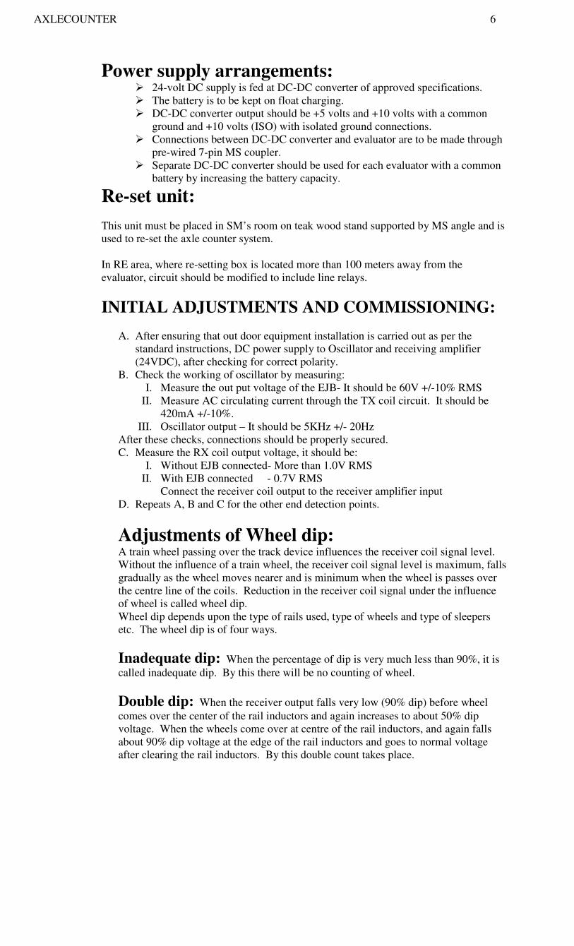
Power supply arrangements: � 24-volt DC supply is fed at DC-DC converter of approved specifications.
� The battery is to be kept on float charging.
� DC-DC converter output should be +5 volts and +10 volts with a common
ground and +10 volts (ISO) with isolated ground connections.
� Connections between DC-DC converter and evaluator are to be made through
pre-wired 7-pin MS coupler.
� Separate DC-DC converter should be used for each evaluator with a common
battery by increasing the battery capacity.
Re-set unit:
This unit must be placed in SM’s room on teak wood stand supported by MS angle and is
used to re-set the axle counter system.
In RE area, where re-setting box is located more than 100 meters away from the
evaluator, circuit should be modified to include line relays.
INITIAL ADJUSTMENTS AND COMMISSIONING:
A. After ensuring that out door equipment installation is carried out as per the
standard instructions, DC power supply to Oscillator and receiving amplifier
(24VDC), after checking for correct polarity.
B. Check the working of oscillator by measuring:
I. Measure the out put voltage of the EJB- It should be 60V +/-10% RMS
II. Measure AC circulating current through the TX coil circuit. It should be
420mA +/-10%.
III. Oscillator output – It should be 5KHz +/- 20Hz
After these checks, connections should be properly secured.
C. Measure the RX coil output voltage, it should be:
I. Without EJB connected- More than 1.0V RMS
II. With EJB connected - 0.7V RMS
Connect the receiver coil output to the receiver amplifier input
D. Repeats A, B and C for the other end detection points.
Adjustments of Wheel dip: A train wheel passing over the track device influences the receiver coil signal level.
Without the influence of a train wheel, the receiver coil signal level is maximum, falls
gradually as the wheel moves nearer and is minimum when the wheel is passes over
the centre line of the coils. Reduction in the receiver coil signal under the influence
of wheel is called wheel dip.
Wheel dip depends upon the type of rails used, type of wheels and type of sleepers
etc. The wheel dip is of four ways.
Inadequate dip: When the percentage of dip is very much less than 90%, it is
called inadequate dip. By this there will be no counting of wheel.
Double dip: When the receiver output falls very low (90% dip) before wheel
comes over the center of the rail inductors and again increases to about 50% dip
voltage. When the wheels come over at centre of the rail inductors, and again falls
about 90% dip voltage at the edge of the rail inductors and goes to normal voltage
after clearing the rail inductors. By this double count takes place.

AXLECOUNTER 7
Very slight double dip:The change in voltage between first dip and second
dip is very less (less than 50%). With this very slight double dip occurs. This dip is
slightly broadened. This is the optimally correct adjustment of the wheel dip.
Sharp Wheel Dip:This dip occurs when the wheel comes over the centre of
the rail inductors and it will be more than 90%. This is full dip and it is correct
adjustment.
The adjustment of the wheel dip is to be carried out with the help of a dummy wheel
and a high input impedance sensitive-multimeter.
Place the calibrated dummy wheel on the rail at the centre of the rail inductors.
Observe the drop in the output voltage of the receiving coil. Adjust the TX coil
slightly up or down in the serrations so that the drop in voltage is 90% or more.
RX coil output without dummy wheel should be between 0.7V to 1.0V RMS. With
dummy wheel, it should be at least 10% below normal signal. Adjust the other
inductors similarly.
NOTE: Dummy wheels has calibrated and graded markings. By adjusting markings,
the depth of the dummy wheel influencing the received signals can be adjusted for
different sections of rails.
However, this is not required when nylon packing is given to raise the height as per
the rail.
For 90 lbs rail - 3 mm thickness nylon packing
52Kg rail - 12 mm thickness nylon packing
60Kg rail - 18 mm thickness nylon packing
Staggering: The track transducers are to be fitted in staggering position on the rails. Maximum
200mm; minimum 150mm; optional 175mm.
It is only from the stagger of these signals the logic circuit provided in the evaluator
discriminate the direction of the movement and connect the counting pulse either to
the IN counter or to the OUT counter as the case may be.
Adjustment of EJB output: a) Measure output voltage of EJB without Evaluator connected. It should be
more than 1.0V RMS.
b) Measure output voltage of EJB with Evaluator connected. It should be more
than 0.6V RMS.
Adjustment of Indoor Equipment (Evaluator):
1. Check that the outdoor communication cable has been terminated properly on
cable termination rack.
2. Check that connection has been made between the termination rack and
evaluator
3. Battery charger and batteries have been connected to DC-DC converter
properly and output of DC-DC converter has been connected to the evaluator.
4. Check that trolley suppression circuit has been wired properly.
5. Check that the re-set circuits has been wired properly.

AXLECOUNTER 8
6. Now, switch on DC-DC converter. Random counting will be seen on the
display unit. Operate there-set switch. The random counting should get
disappeared. ie. Display will show no count.
7. Measure the open circuit voltage on the termination rack and see that it should
be 500mV peak to peak. Connect all the cards and pull out card no .1
8. Connect the card no.1 to the evaluator through extension card, keep the
potentiometer at maximum in clock wise direction and ensure that output of
card no.1 is about 150mV RMS for each channel.
9. Now adjust the output of card no.1with the help of potentiometer for a value of
105mV RMS and also ensure that it is pure sinusoidal.
10. With all cards inserted press the re-set switch and see there should not be any
count on display unit. The EV1, EV2 and CLR LEDs only will lit. Check the
EV and SUP relays are picked up and EV and SUP relay voltage is 8+/-1
VDC.
11. Under dropped condition, voltage across the EV and SUP relay should be less
than 0.5V.
Testing of the System Working:
1. Connect one switch across the incoming lead of channel A and another
switch across the incoming lead of channel B
2. The switches should be connected in such a way that when they are
operated, shorts the two conductors of the incoming channels.
3. Operate the switches in the following sequence and observe the counts in
the display unit:-
Step I. Operate the switch of channel B – No count
Step II. Operate the switch of channel A – One OUT count
Step III. Normalize the switch of channel B – One more OUT count
Step IV. Normalize the switch of channel A - No count
4. Now, disconnect the switches and connect the oscilloscope at the output of
the channels and check the dip. The dip should be 90% or more. If not, re-
adjust transmitter housing.
5. Drop all channel input except channel A and observe the counting during
the passage of train, as per number of axles in the train. Then the display
should show the same number of axles. Should show IN count and OUT
count. If the display unit shows count then, there may be a problem of
Double Dip or loose connection. If it is double dip, then it should be
avoided by re-adjusting the TX coil position. This test should be repeated
for all channels individually and ensure that counting is correct.
6. After ensuring that the unit is counting properly and EV and SUP relays
are functioning properly, connect +10V supply through front contact of
trolley protection track relay. Measure this voltage at card number 3.
Check that no counting takes place when an insulated trolley is moved over
the track detection unit.
7. Remove 10V (trolley protection voltage ) and now short each channel one
at a time and ensure that after each short SUP relay should drop and do not
pick up unless is re-set. The voltage on EV and SUP relays should not be
more than 0.5V when the relays are de-energized.
AXLECOUNTER 9
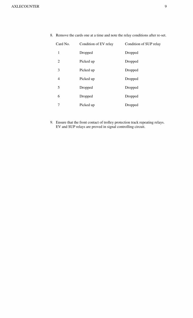
8. Remove the cards one at a time and note the relay conditions after re-set.
Card No. Condition of EV relay Condition of SUP relay
1 Dropped Dropped
2 Picked up Dropped
3 Picked up Dropped
4 Picked up Dropped
5 Dropped Dropped
6 Dropped Dropped
7 Picked up Dropped
9. Ensure that the front contact of trolley protection track repeating relays.
EV and SUP relays are proved in signal controlling circuit.

AXLECOUNTER 10
TROUBLE SHOOTING CHART Fault localization in Track Side Equipment:
OK NOT OK
OK NOT OK
OK NOT OK
OK
OK NOT OK
OK OK NOT OK
OK NOT OK
OK
STILL NOT OK
Measure card no.1 all channel output voltage
Measure channel input to evaluator
Check card no. 1 of EV
Soldering connections.
Adjust levels if
required on card no.1
Check channel input
Termination at EV
room.
Check RX / AMF output at
terminal C1,C2 & C3,C4 as
in wiring diagram
Attend to
terminal and
rectify
One RX/AMF output
voltage -NIL
Both RX/AMF output
voltage- NIL
Check input of RX/AMF at
terminals B 5 26 or B 7 28
Replace RX/AMF card of that
defective channel
Check RX coil
output connections
Check oscillator
output voltage across
terminals
Check TX coil voltages
of A&B channels across
Check feed of input
12/24VDC to oscillators
power supply connections
across
Replace receiver coil,
which is defective
Replace TX coil,
Which is defective
Replace oscillator
unit TX card
Rectify and restore
In both these cases after replacement of cards
Change oscillator, Receiver amplifier unit

AXLECOUNTER 11
Typical failure and Trouble Shooting
List of normal troubles Trouble shooting procedure and their
remedies.
1) DC fuse blowing 1) Check DC supply 12V/24V to
location box terminals, if normal
2) Check DC fuse, if provided
3) Check DC current drain
(200mA), if abnormal
4) Check coupler SK-2 wires,
whether any short, loose
connection or break, and confirm
whether supply is going to pin D
(+24V) and pin E (-24V) to EJ
box.
5) If still high current drain, replace
EJ box or replace Reg. OSC card
RA-I card or RA-II card one by
One. Because of short circuit in
any one of these cards the fuse
may be blowing.
2) OSC output NIL 1) Check OSC output voltage
(approx. 56V to 64VAC) across
SK-2 coupler pin A&B wires.
3) OSC output low or dropping 2) Check OSC frequency 5kHz +/-
20Hz, if normal
4) OSC frequency changed. 3) Check total circulation current (I)
in both TX-1 and TX-2 coils in
series. It should be 460mA to
520mA (approximately)
4) Check circulation of current in
TX-1 and TX-2 separately. It
should be same as in step 3 if
normal otherwise disconnect SK-2
coupler and check resistance
between pin A & B. It should be
around 40 ohms if normal, or else
replace REG OSC card. Because of
any short circuit or components
failure in the cards. Connect the SK-
2 coupler to EJ box again.
5) Check voltage across TX-1 and
TX-2 coils in series.
6) Check voltage drop across each
TX coil it should be approx. 60V/2
or 30VAC each, if it is normal
7) Disconnect TX coils from
terminals and check resistance of
the TX coils (approx. 1 to 2 ohms
each)
If found any abnormality, replace
TX coils.

AXLECOUNTER 12
5) Double dip occurs 1) Adjust the height of TX and RX
coils on the base plate as per
procedure.
6) 90% dip not available. 1) Check SK-1 coupler wires
whether any short, loose connection
or break and confirm whether RX-2
in wires going to pin E & F
respectively and check normal
voltage (0.7V to 1.2 VAC) across
the pins.
7) RA-I out put- Nil 2) Confirm whether RA-1 out wires
8) RA-2 out put –Nil going to pin A&B and RA-2 out
9) RA-I output –Nil wires going to pins G & H
10) RA-II output – Low respectively and check normal out
put voltage (0.7V to 1.2 VAC)
across the pins
3) Check RA-1 out at the terminals
going to quad cables (approx. 0.7V
to 1.2 VAC)
4) Check RA-1out at terminals
going tot quad cables (approx. 0.7V
to 1.2 VAC) or else replace RA-1
and RA-2 card one by one.
AXLECOUNTER 13
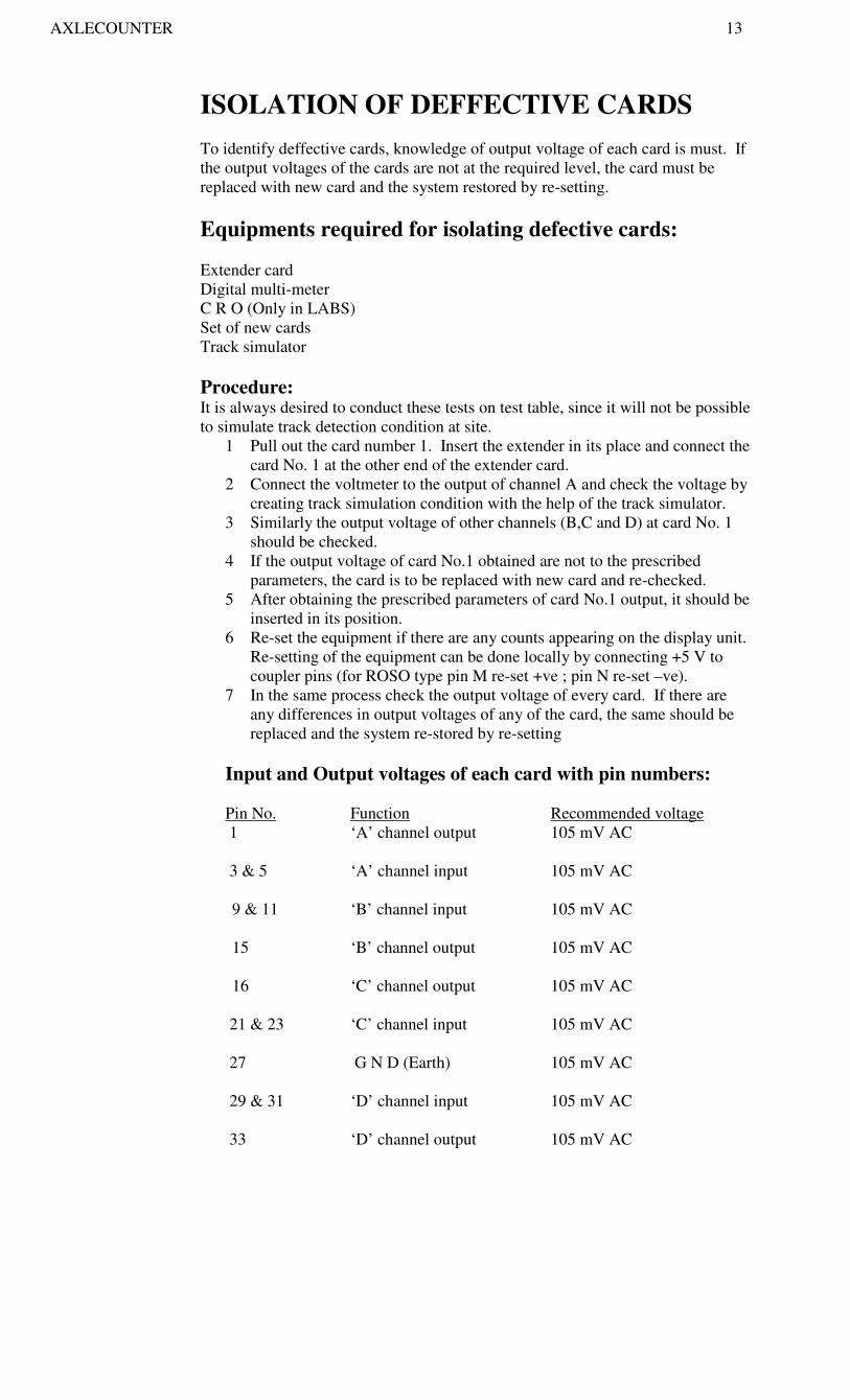
ISOLATION OF DEFFECTIVE CARDS
To identify deffective cards, knowledge of output voltage of each card is must. If
the output voltages of the cards are not at the required level, the card must be
replaced with new card and the system restored by re-setting.
Equipments required for isolating defective cards:
Extender card
Digital multi-meter
C R O (Only in LABS)
Set of new cards
Track simulator
Procedure: It is always desired to conduct these tests on test table, since it will not be possible
to simulate track detection condition at site.
1 Pull out the card number 1. Insert the extender in its place and connect the
card No. 1 at the other end of the extender card.
2 Connect the voltmeter to the output of channel A and check the voltage by
creating track simulation condition with the help of the track simulator.
3 Similarly the output voltage of other channels (B,C and D) at card No. 1
should be checked.
4 If the output voltage of card No.1 obtained are not to the prescribed
parameters, the card is to be replaced with new card and re-checked.
5 After obtaining the prescribed parameters of card No.1 output, it should be
inserted in its position.
6 Re-set the equipment if there are any counts appearing on the display unit.
Re-setting of the equipment can be done locally by connecting +5 V to
coupler pins (for ROSO type pin M re-set +ve ; pin N re-set –ve).
7 In the same process check the output voltage of every card. If there are
any differences in output voltages of any of the card, the same should be
replaced and the system re-stored by re-setting
Input and Output voltages of each card with pin numbers:
Pin No. Function Recommended voltage
1 ‘A’ channel output 105 mV AC
3 & 5 ‘A’ channel input 105 mV AC
9 & 11 ‘B’ channel input 105 mV AC
15 ‘B’ channel output 105 mV AC
16 ‘C’ channel output 105 mV AC
21 & 23 ‘C’ channel input 105 mV AC
27 G N D (Earth) 105 mV AC
29 & 31 ‘D’ channel input 105 mV AC
33 ‘D’ channel output 105 mV AC

AXLECOUNTER 14
Card No.2
Pin No. Function Recommended voltage
1 ‘A’ channel output 105 mVAC (2VDC)
5 & 29 +10V 10VDC
9 ‘B’ channel output 105 mVAC (2VDC)
17 G N D (Earth)
25 ‘C’ channel output 105 mVAC (2VDC)
31
2
Card No. 3
‘D’ channel output
‘A’ out via RSR back contact
105 mVAC (2VDC)
Pin No. Function Recommended voltage
8 GND earth proving 4.5 VDC
9 ‘A’ output pulse shaper 4.5 VDC
13 ‘B’ output pulse shaper 4.5 VDC
21 ‘C’ output pulse shaper 4.5 VDC
25 ‘D’ output pulse shaper 4.5 VDC
11 & 13
20
25 & 26
GDD (Earth)
+10V
5KHz signal to SUP relay drive
unit to gain amplifier drive.
--------
10VDC
105 mVDC
NOTE:
Input to card no.3 at pin 1,7,27,33 will be 2VDC when track is shunted. (No trolley
protection to 2,5,29 and 32 pins) and 3VDC when track is clear.

AXLECOUNTER 15
Card no.4
Pin No. Function Recommended voltage
1 GND
5 IOSO 2 IN OUT count
Supervision normally too old
Old evaluator New Card
8 IN count pulse normal SV
O
SV
O
For each count
9 OUT count pulse
Normal count
10 OUT count pulse
COUNT 4.5
0 V
NORMAL
27
21
16
IN OUT pulse
IN OUT supervision No.1
IN OUT supervision No.2
(ISOI) NORMALLY 3 V
(ISO2) HIGH
24
EV2 voltage from card No.5 (ISO2) HIGH
11
22
23
12
15
ROI
ISO1
NORO2
VOC ( R )
GNR ( R )
Normally low 0 V to 8 V
Normally low 0 V to 8 V
Normally low 0 V to 8 V
5 VDC
5 VDC

AXLECOUNTER 16
Card No. 5
Pin No. Function Recommended voltage
5 IN count supervision - 1 Normally High >3
7 IN count supervision - 2 Normally High >3
11 EV1 Normally High >3
25 EV2 Normally High >3
25 EV3 Normally High >3
27
29
19
21
Card No. 6
Pin No.
1
3
6
10
14
OUT count supervision – 1
OUT count supervision - 2
GND
GND ( R )
Function
Voltage monitor Output
EV Relay Drive voltage +ve
EV Relay Drive voltage -ve
Failure supervision
Level Detector A channel
Normally High >3
Normally High >3
Old version New version
>4VDC 3.8 to 5.5VDC
8V+/-1V >11V
8V+/-1V >11V
>3VDC
>3VDC
24 Level Detector B channel >3VDC
20
32
2
31
Level Detector C channel
Level Detector D channel
GND
GND ( R )
>3VDC
>3VDC
>3VDC
>3VDC

AXLECOUNTER 17
Card No. 7
Pin No. Function Recommended New version
Voltage
4 +ve SUPR Drive 8V +/-1V(Open circuit) >11V
3 -ve SUPR Drive
19 10KHz square wave
21 Level Detector Drive A >3V
6 Level Detector Drive B >3V
1 Level Detector Drive C >3V
31 Level Detector Drive D >3V
Warning: Any mistake in power supply connection may lead to serious and irreparable damage to the equipment.

AXLECOUNTER 18
UNIVERSAL AXLE COUNTER
By merging single entry and multi-entry axle counters, a new axle counter is developed
known as Universal Axle Counter.
A single unit of universal axle counter can be used to detect up to maximum 4 detection
points.
3D system can be converted into 4D system and vice-versa by changing jumpers in the
card. For conversion of 3D or 4D into 2D, card 2,4 and 5 are to be replaced by respective
dummy cards and necessary jumpers to be changed.
The cards in universal axle counters are:
Card No. 1 - Attenuator / Amplifier / Rectifier
Card No. 2 - Attenuator / Amplifier / Rectifier
Card No. 3 - Pulse shaper
Card No. 4 - Pulse shaper
Card No. 5 - Logic No.1
Card No. 6 - Logic No.2
Card No. 7 - Counter comparator
Card No. 8 - General supervision
Card No. 9 - Relay driver
Card No. 1 reads for ABCD channels and Card No.2 reads for EFGH.
These channels are used in 3D and 4D system.
Card No. 5 is also used for 3D and 4D system.
Equipments for Universal Axle Counter System: 1 Relay rack (Common for all models) - 1No.
2 Evaluator - 1No.
3 DC-DC converter - 1No.
4 Electronic Junction Box - 2 Nos. for 2D system
- 3 Nos. for 3D system
- 4 Nos. for 4D system
5. Re-set box - 1 No.
6. Track Device Assembly - 2 Nos. for 2D system
- 3 Nos. for 3D system
- 4 Nos. for 4D system
7. Line Verification Box - 1 No.
8. EVR and SUPR relay - 1000 ohms shelf type or 4F/4B
relay or ‘Q’ style plug-in Relay
(1000 ohms). 4F/4B and voltage
is more than 11V.
POWER SUPPLY ARRANGEMENT
Evaluator - 24V Min. 21.6V Max. 28.8V Current 1.5Amps
EJB - 24V Min. 21.6V Max. 28.8V Current <250mAmps.
Re-set Box Min. 21.6V Max. 28.8V Current 500mAmps.

AXLECOUNTER 19
INTERMEDIATE BLOCK SIGNAL
Definition: Intermediate block signaling means an arrangement of signaling on double line in which,
a long block section is split into two portions, each constituting a separate block section
by providing an Intermediate Block stop Signal. The IBS is equivalent to that of class
‘C’ station at which trains are not booked to stop.
Advantages of IBS: Under absolute block system of working “No train shall be allowed to leave a block
station unless line clear has been obtained from block station in advance”.
And on double line, such line clear shall not be given unless the line is clear not only up
to the first stop signal at which such line clear is given but for an adequate distance
beyond it. (Reference G.R.8.01)
With this system of working only one train can be allowed to enter into the block section.
A second train can be sent only on clearance of block section by last preceding train.
This affects the section capacity very badly, where the density of traffic is very heavy,
since trains take more time to clear the block section. So as to increase the section
capacity to meet the traffic demand, the entire block section on double line is splitted into
two portions with IBS arrangement. IBS is treated as a class’C’ station on double line,
section remotely controlled from block station in rear.
Requirements for IBS: � IBS shall be provided on double line only.
� Providing an intermediate stop signal should split the block section. Such stop
signal should be provided with telephone communication with the station in rear.
� The presence of stop signal should be warned by a distant signal (Double distant
where in use) provided at minimum braking distance in rear.
� A continuous track circuit extending from last stop signal of the block station in
rear to a point not less than 400 meters in advance of IBS should be provided.
Axle counter working may be provided in lieu of track circuit.
� A control to ensure that LSS of block station is automatically replaced to ON by
the passage of train and that it cannot be taken OFF again until track circuit or
axle counter portion of the line is cleared (400 meters beyond IBS)
� A control to ensure that IBS cannot be taken OFF until line clear has been
received from the block station in advance.
� A means to ensure that IBS is replaced to ON by the passage of train and
maintained in that position until the train has cleared the block section and fresh
line clear is obtained.
� In order to attract the attention of the duty Station Master at sending station, the
following audio-cum-visual indications are to be provided:
1) When the power supply to the IBS fails OR any of the lamps of IBS or IB
distant is failed.
2) When the train enters the Axle counter section or block section.
3) When the block section is occupied, entry of a second train by passing IBS
at on.
4) An indication to prove the circuits associated with axle counter section is
in order and axle counter section is clear or occupied.
Pressing the acknowledgement button can stop the alarm in 1 and 3.
Putting back LSS lever/knob OR IBS can stop the alarm in 2
lever/knob to normal position.
AXLECOUNTER 20
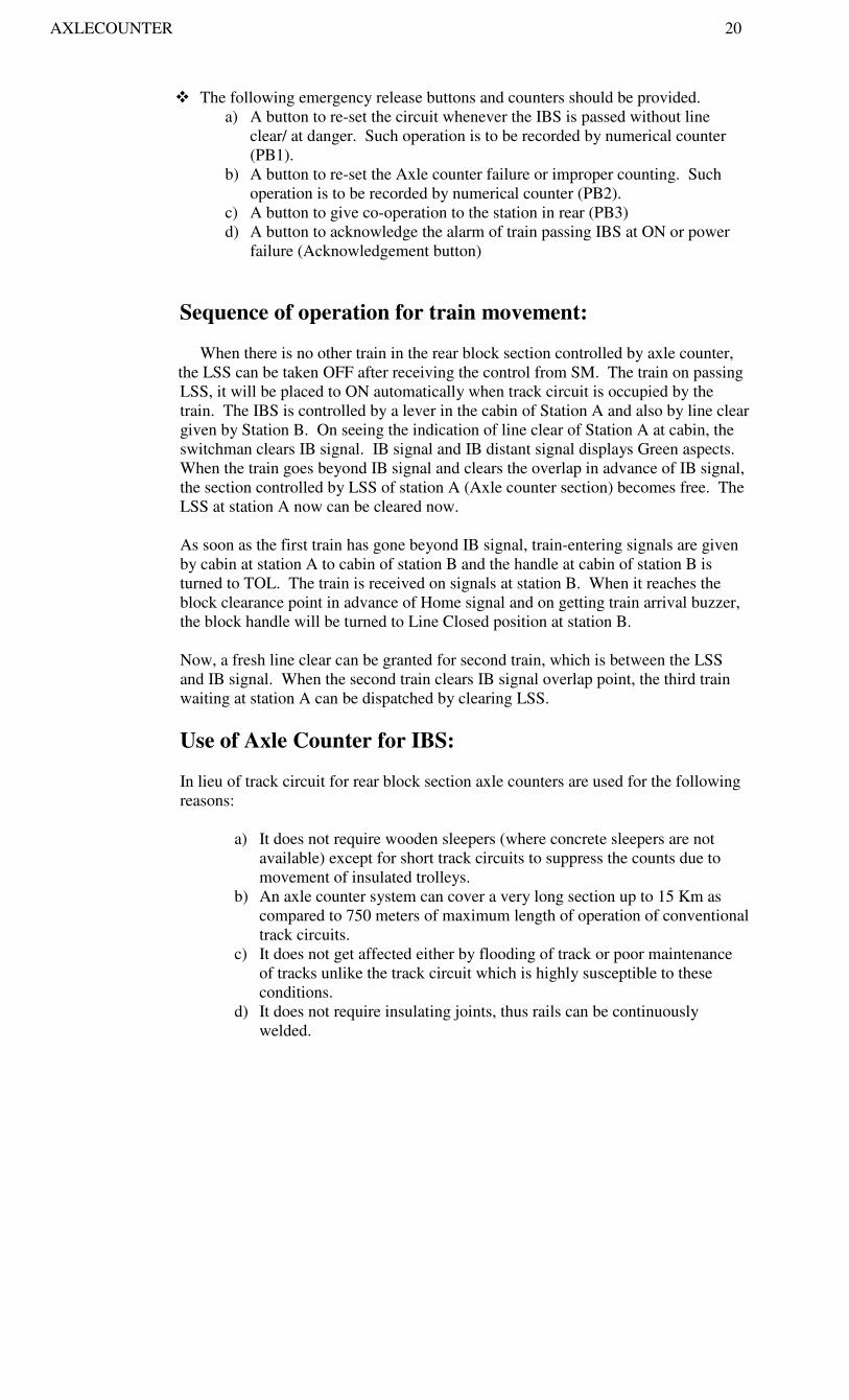
� The following emergency release buttons and counters should be provided.
a) A button to re-set the circuit whenever the IBS is passed without line
clear/ at danger. Such operation is to be recorded by numerical counter
(PB1).
b) A button to re-set the Axle counter failure or improper counting. Such
operation is to be recorded by numerical counter (PB2).
c) A button to give co-operation to the station in rear (PB3)
d) A button to acknowledge the alarm of train passing IBS at ON or power
failure (Acknowledgement button)
Sequence of operation for train movement:
When there is no other train in the rear block section controlled by axle counter,
the LSS can be taken OFF after receiving the control from SM. The train on passing
LSS, it will be placed to ON automatically when track circuit is occupied by the
train. The IBS is controlled by a lever in the cabin of Station A and also by line clear
given by Station B. On seeing the indication of line clear of Station A at cabin, the
switchman clears IB signal. IB signal and IB distant signal displays Green aspects.
When the train goes beyond IB signal and clears the overlap in advance of IB signal,
the section controlled by LSS of station A (Axle counter section) becomes free. The
LSS at station A now can be cleared now.
As soon as the first train has gone beyond IB signal, train-entering signals are given
by cabin at station A to cabin of station B and the handle at cabin of station B is
turned to TOL. The train is received on signals at station B. When it reaches the
block clearance point in advance of Home signal and on getting train arrival buzzer,
the block handle will be turned to Line Closed position at station B.
Now, a fresh line clear can be granted for second train, which is between the LSS
and IB signal. When the second train clears IB signal overlap point, the third train
waiting at station A can be dispatched by clearing LSS.
Use of Axle Counter for IBS:
In lieu of track circuit for rear block section axle counters are used for the following
reasons:
a) It does not require wooden sleepers (where concrete sleepers are not
available) except for short track circuits to suppress the counts due to
movement of insulated trolleys.
b) An axle counter system can cover a very long section up to 15 Km as
compared to 750 meters of maximum length of operation of conventional
track circuits.
c) It does not get affected either by flooding of track or poor maintenance
of tracks unlike the track circuit which is highly susceptible to these
conditions.
d) It does not require insulating joints, thus rails can be continuously
welded.

AXLECOUNTER 21
Re-setting procedure:
There are two type of re-setting involved. In first case, if the axle counter fails to show
clear indication when the train has fully cleared the overlap in advance of IB signal. This
is indicated by ACPKR. The re-setting of axle counter to be done jointly by SMs of
station A and station B only after the train has arrived completely at the station and so
verified by SM of station B. SM of station B has to press PB3 button and SM of station
A has to press PB1 simultaneously till such time the axle counter shows clear indication.
A counter records this re-setting.
In the second case, when the train has passed the IB signal at danger, which is indicated
by K1 and buzzer, LSS cannot be cleared for subsequent train till such time the ACZR
relay picks up, which had dropped due to train passing IB signal at danger. This resetting
process is also done after the train has completely arrived at station B and so verified by
SM of station B. SM of station A has to press PB1 and SM of station B has to press PB3
buttons simultaneously till such time the indication disappears. A counter also records
this re-setting. LSS can be cleared only after this re-setting.
In both cases, the circuit will only permit one train to be in the IB signalling system for
the duration of the failure and normal working can be restored only when the re-setting is
done. Before the re-setting (any type) is done by the SM in co-operation, SM must verify
that all the trains supposed to be in the section have arrived completely at the receiving
station and there are no trains in the IB signalling system.
Procedure to be followed for passing IB signal at ON aspect or signal at blank: As per G.R.3.75 whenever the driver comes across an IB signal at danger or blank, he has
to wait and contact on telephone provided on IB signal post with SM/Switchman of the
station or cabin, as the case may be, who will tell him the reasons for the signal failure
and when authorized by the station A only then the driver can pass the IB signal at danger
and proceed to station B.
In case the telephone is defective, or communication is not possible with station A, the
driver after waiting for 5 minutes can pass the IB signal at danger and proceed at a speed
of 15KMPH which should be reduced to 8KMPH in case of inadequate visibility.
The driver should proceed at restricted speed, looking out for any possible obstruction till
he reaches station B and on arrival at station B the system should be re-set by the joint
co-operation of both then SMs and the IB signalling system can be normalized.
Description of Relays and Circuitry:
LSS-SR: It is a stick relay, which sticks through LSS TPR and its own front contact.
This relay will drop as soon as LSS TPR drops and once dropped it will not pick up
unless LSS TPR picks up, after ensuring that axle counter is showing occupied and
proving that EVR, SUPR and NSR is also down. In the holding circuit of this relay in
addition to the contact of SR, contact of NSR is also proved in parallel to ensure that
whenever the LSS TPR relay drops momentarily and picks up, the SR will remain pick
up.
LSS-YR: Controls the LSS and it proves that the axle counter portion is clear. No train
has gone beyond IB signal by passing the signal at danger and also that SR is up and HSR
down.(due to ACPR up). It also proves the track circuit ahead of IB signal are up and
also proves the slot given by SM for clearing LSS. The contacts of LSS YR are used for
picking LSS DR when the lever is reversed. LSS DR controls the feed to LSS.

AXLECOUNTER 22
NSR (Normal Stick Relay)
This relay is a repeater of LSS SR and ACPR and it will stick through its own front
contact and through LSS lever normal band. This relay helps in enabling LSS SR to pick
up immediately during momentary failure and picking up of LSS TPR as explained
above.
During normal working, this is one of the relays holding ACZR in pick up position.
ACPR (Axle Counter section clear Proving Relay):
When picked, it proves axle counter section is free of any train and depends upon EVR,
SUPR, SR and also ensures LSS YR and SMs slot for LSS are not given and also lever is
normal before ACPR can pick up. Once picked up, the relay remains picked up even if
the LSS is cleared or the lever is reversed. Drops when the axle counter section is
occupied or any system failure of axle counter. This relay also proves that once it is
dropped, due to section being occupied, the SMs slot the relay controlling the advanced
starter lever are all put back to normal before ACPR can pick up once again. The SUPR
front contact is also bypassed by LSS DR which ensures that after the LSS is cleared, if
SUPR is dropped momentarily due to variation in the output from track devices on
account of trolleys being placed on track device, etc., the ACPR will not drop and cause
the signal to go to danger.
ASR1 & ASR2: These relays pick up when the handle is turned to TOL at the receiving
end after making sure that LCPR is down and IB signal is not showing Green aspect.
After ASR1 Picking up ASR2 will pick up. Once picked up they remain stick through
their front contact and also through IBS TPR The use of two relay also ensure that handle
has to be turned to TOL for considerable period before ASR2 relay can pick up. Further,
to ensure that two relays do not drop when the contacts of IBS TPR break momentarily,
the same is by-passed by contacts of ASR1, ASR2, NSR and back contact of LCPR.
IBS-HSR (IB Signal Stick Relay):
The relay is normally de-energized and picks up when the axle counter section is
occupied and the train is approaching the IB signal and IB signal is cleared and
displaying the clear aspect. Once train has gone beyond IB signal and has occupied IB
track circuit even after the IB TPR drops and IB signal goes to danger, this relay will
continue to hold through IB TPR drop contact and its own front contact. By the time the
train clears IB TPR, the ACPR picks up due to axle counter section, section free and
hence IB HSR drops and does not pick up again until the IB signal is cleared second time.
This is one of the relays, which helps in non-dropping of ACZR relay when a train has
passed IB signal in the clear condition and comes on the IB track circuit.
PBPR (Push Button Proving Relay):
This relay picks up whenever the ACZR is down and is used for silencing the buzzer.
Similarly, when the power failure takes place or the IB signal is completely blank, the
buzzer would appear once again and it is to be silenced only by picking up XR relay by
pressing the acknowledgement button. The bell, which sounds in conjunction with K2 &
K3 indications, is silenced, whenever LSS lever or IB signal lever is replaced to the
normal position.

AXLECOUNTER 23
ACRSR (Axle Counter Re-setting Relay):
This relay is used for re-setting of axle counter system. Whenever axle counter shows
occupied even when there is no axle left in the axle counter portion. For this the sending
station SM has to press PB2 and receiving station SM has to press PB3. When both these
conditions are satisfied, CRR picks up at sending station, and then ACRSR will pick up
after proving that axle counter relay ACPR is down. Once ACRSR is picked up, a
counter registers the axle counter re-setting and the relay R inside the evaluator picks up
which in turn will re-set EVR and SUPR and enable ACPR to pick up again.
ACZR (Axle Counter Special Relay):
The purpose of this relay is to detect whether a train has passed IBS at ON. This relay
remains normally pick up and it has three holding paths:
I. Through LSS NSR up;
II. Through IBS SR up and
III. Through IBS TPR down.
This relay drops only when all three controls have failed or not available. As long as
IBS TPR is up, ACZR will hold through its front contact and whenever IBS TPR is down
for any reason, ACZR will hold through IBS TPR back contact and as soon as HSR
picks up ACZR will hold through HSR front contact even if the train occupies IBS track.
Once train clears IBS track, even if HSR drops, the ACZR will continue to hold through
IBS TPR picked up contact. But if a train has passed IBS at ON, HSR would not have
picked up and as soon as the train comes on IBS track, all the three paths for ACZR will
be broken and it will drop. For it to pick up again it requires re-setting of IB section by
co-operation of both the SMs, with the sending SM pressing PB1 the relay ACZNR
picks up after proving ACZR in down condition and proving IBS TPR is up. On getting
the co-operation indication given at station at A and in addition the relay ACZNPR picks
up at sending end with in this duration CRR and ACZNR remain picked up. As soon as
ACZNPR picks up the relay ACZR will pick up and subsequently ACZR will hold
through its own front contact.
A special counter also registers the operation of ACZNR. When ACZR has picked up
ACZNR and ACZNPR will drop. CRR drops when PB3 is released at receiving end.
Power Supply Arrangement for IBS:
Power supply required at IBS location is 110VAC for signal lighting and 24VDC for
operating the various repeater relays from IBS location to the station A. In RE Area,
Up/Down AT supply shall be provided at IB signal location. In Non-RE Area, 230VAC
is taken through 25sq.mm.2 core aluminum power cable from station A and station B to
the IBS location from where it can be stepped down to 110VAC for signal lighting and
also used for battery charger. This 230VAC is tapped from auxiliary transformers of the
traction supply at the cabin of station A or station B, if AT supply is not provided at IBS
location. Normally supply is tapped from two auxiliary transformers so that in case of
failure of one of the AT supplies, the other can be manually selected. In case of AT
supply provided at IBS location, auto-change over arrangement is provided for this
purpose.

AXLECOUNTER 24
Apart from power cable, one quad is required for carrying the axle counter track device at
the overlap point of IBS. In addition 12-core cable (Two for controlling the IBS, six for
repeating relays, two for end to end cancellation circuit from station A to station B) is
required. Additional 6 core for RE cutting between IBS; IBS-D and IBS-ID and lighting
circuit for distant signals are also required.
Similarly cable is required for telephone communication between IBS location and
station A.
*******************