module 3 introduction to basic standard knowledge for … course module/module 3.pdf ·...
TRANSCRIPT
PANAMA MARITIME AUTHORITYInternational Representative Office
New York, USA
MODULE 3
Introduction to basic standard knowledge for ASI Inspectors
INTRODUCTION• This module is distributed with the sole purpose
to provide basic standard ship knowledge to all ASI inspectors.
• This material is intended for internal use of the Panama Maritime Authority only.
• Panama Maritime Authority shall not be held liable from the unauthorized and illegal distribution, commercialization or modification from the original version and contents of this module.
Chapter 5 – Forces on a Ship1.General
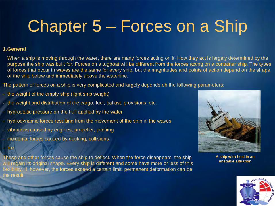
When a ship is moving through the water, there are many forces acting on it. How they act is largely determined by the purpose the ship was built for. Forces on a tugboat will be different from the forces acting on a container ship. The types of forces that occur in waves are the same for every ship, but the magnitudes and points of action depend on the shape of the ship below and immediately above the waterline.
The pattern of forces on a ship is very complicated and largely depends oh the following parameters:
- the weight of the empty ship (light ship weight)
- the weight and distribution of the cargo, fuel, ballast, provisions, etc.
- hydrostatic pressure on the hull applied by the water
- hydrodynamic forces resulting from the movement of the ship in the waves
- vibrations caused by engines, propeller, pitching
- incidental forces caused by docking, collisions
- Ice
These and other forces cause the ship to deflect. When the force disappears, the ship will regain its original shape. Every ship is different and some have more or less of this flexibility. If, however, the forces exceed a certain limit, permanent deformation can be the result.
A ship with heel in an unstable situation

2 Longitudinal Strength
2.1 Shearing ForcesWhen a ship is in calm water, the total upward force will equal the total weight of the ship. Locally this equilibrium willnot be realized because the ship is not a rectangular homogeneous object. The local differences between upwardpressure and the local weight give rise to shearing forces that lead to longitudinal tensions. The shearing force is theforce that wants to shift the (transverse) plane from one part of the ship to another. The submerged part of the shipclearly shows the difference in volume between the midship, the fore and the aft ship; this is the reason for thedifference in upward force.In the drawing on the right of this page a part of the aft ship is shown along with the digging force near a bulkhead. Theshearing force at the bulkhead is 400 - 200 = 200 tons. The downward force causes a hogging moment of 400 tons x 6meters. The upward force causes a sagging moment of 200 t x 3m.The bending moment at the bulkhead is: 2400 tm - 600tm = 1800m (hogging) The longitudinal forces occur because:a.the weights in the ship are not homogeneous in the fore and aft directionb.the upward force differs due to the shape of the underwater body.
200 tons shearing force at this bulkhead
The submerged part of the chip clearly shows the difference in volume between the midships section and the aft section. This explains the difference in upward pressure.
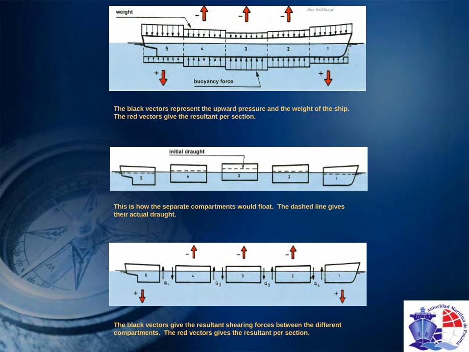
The black vectors represent the upward pressure and the weight of the ship. The red vectors give the resultant per section.
This is how the separate compartments would float. The dashed line gives their actual draught.
The black vectors give the resultant shearing forces between the different compartments. The red vectors gives the resultant per section.
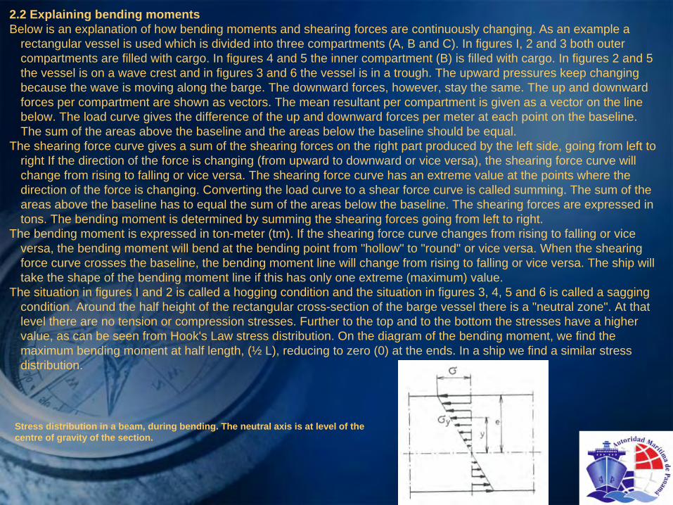
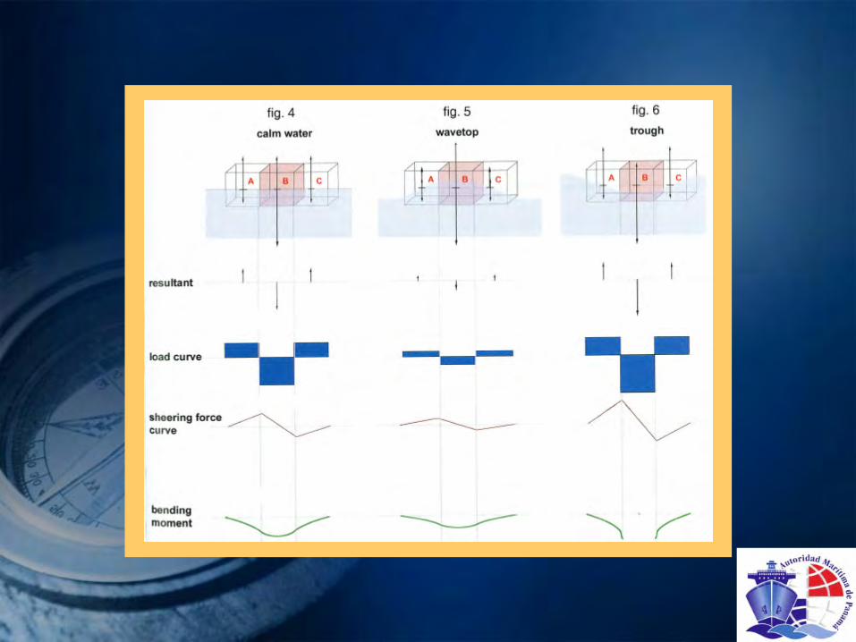
2.2 Explaining bending momentsBelow is an explanation of how bending moments and shearing forces are continuously changing. As an example a
rectangular vessel is used which is divided into three compartments (A, B and C). In figures I, 2 and 3 both outer compartments are filled with cargo. In figures 4 and 5 the inner compartment (B) is filled with cargo. In figures 2 and 5 the vessel is on a wave crest and in figures 3 and 6 the vessel is in a trough. The upward pressures keep changing because the wave is moving along the barge. The downward forces, however, stay the same. The up and downward forces per compartment are shown as vectors. The mean resultant per compartment is given as a vector on the line below. The load curve gives the difference of the up and downward forces per meter at each point on the baseline. The sum of the areas above the baseline and the areas below the baseline should be equal.
The shearing force curve gives a sum of the shearing forces on the right part produced by the left side, going from left to right If the direction of the force is changing (from upward to downward or vice versa), the shearing force curve will change from rising to falling or vice versa. The shearing force curve has an extreme value at the points where the direction of the force is changing. Converting the load curve to a shear force curve is called summing. The sum of the areas above the baseline has to equal the sum of the areas below the baseline. The shearing forces are expressed in tons. The bending moment is determined by summing the shearing forces going from left to right.
The bending moment is expressed in ton-meter (tm). If the shearing force curve changes from rising to falling or vice versa, the bending moment will bend at the bending point from "hollow" to "round" or vice versa. When the shearing force curve crosses the baseline, the bending moment line will change from rising to falling or vice versa. The ship will take the shape of the bending moment line if this has only one extreme (maximum) value.
The situation in figures I and 2 is called a hogging condition and the situation in figures 3, 4, 5 and 6 is called a sagging condition. Around the half height of the rectangular cross-section of the barge vessel there is a "neutral zone". At that level there are no tension or compression stresses. Further to the top and to the bottom the stresses have a higher value, as can be seen from Hook's Law stress distribution. On the diagram of the bending moment, we find the maximum bending moment at half length, (½ L), reducing to zero (0) at the ends. In a ship we find a similar stress distribution.
Stress distribution in a beam, during bending. The neutral axis is at level of the centre of gravity of the section.

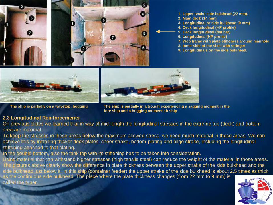
1. Upper snake side bulkhead (22 mm).2. Main deck (14 mm)3. Longitudinal or side bulkhead (9 mm)4. Deck longitudinal (HP profile)5. Deck longitudinal (flat bar)6. Longitudinal (HP profile)7. Web frame with plate stiffeners around manhole8. Inner side of the shell with stringer9. Longitudinals on the side bulkhead.
The ship is partially on a wavetop: hogging The ship is partially in a trough experiencing a sagging moment in the fore ship and a hogging moment aft ship
2.3 Longitudinal ReinforcementsOn previous slides we learned that in way of mid-length the longitudinal stresses in the extreme top (deck) and bottom area are maximal.To keep the stresses in these areas below the maximum allowed stress, we need much material in those areas. We can achieve this by installing thicker deck plates, sheer strake, bottom-plating and bilge strake, including the longitudinal stiffening attached to that plating.In the double bottom, also the tank top with its stiffening has to be taken into consideration.Using material that can withstand higher stresses (high tensile steel) can reduce the weight of the material in those areas.The pictures above clearly show the difference in plate thickness between the upper strake of the side bulkhead and the side bulkhead just below it. In this ship (container feeder) the upper strake of the side bulkhead is about 2.5 times as thick as the continuous side bulkhead. The place where the plate thickness changes (from 22 mm to 9 mm) is called the taper.
2.4 The loading Program
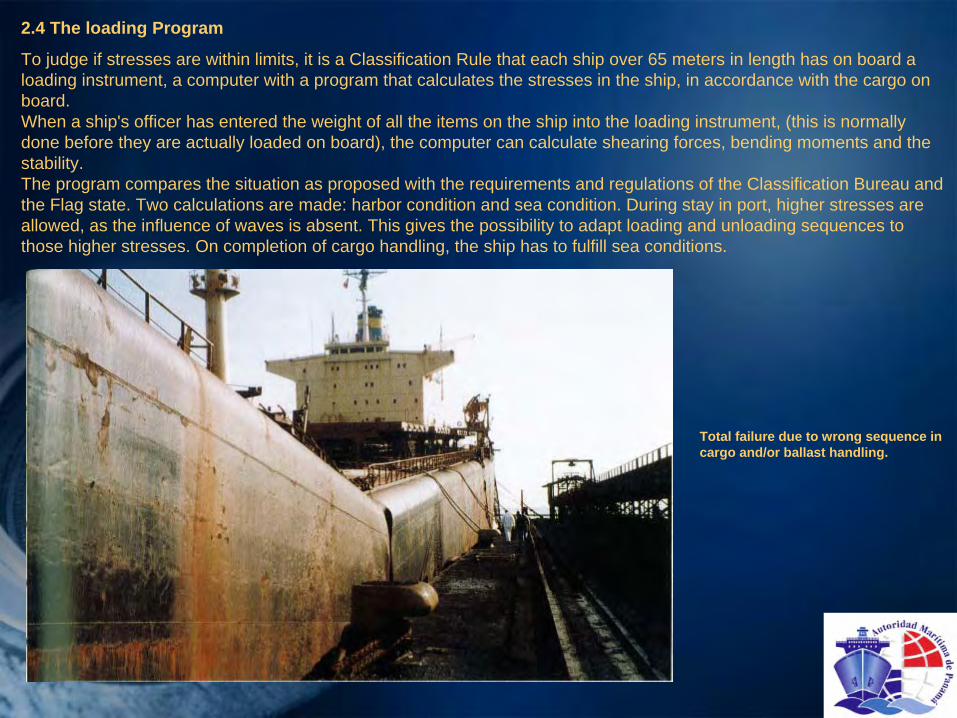
To judge if stresses are within limits, it is a Classification Rule that each ship over 65 meters in length has on board a loading instrument, a computer with a program that calculates the stresses in the ship, in accordance with the cargo on board.When a ship's officer has entered the weight of all the items on the ship into the loading instrument, (this is normally done before they are actually loaded on board), the computer can calculate shearing forces, bending moments and the stability.The program compares the situation as proposed with the requirements and regulations of the Classification Bureau and the Flag state. Two calculations are made: harbor condition and sea condition. During stay in port, higher stresses are allowed, as the influence of waves is absent. This gives the possibility to adapt loading and unloading sequences to those higher stresses. On completion of cargo handling, the ship has to fulfill sea conditions.
Total failure due to wrong sequence in cargo and/or ballast handling.

2.5 Stress distribution and deflection simulation
Stresses in and deflections of the ships hull, due to the various forces working on the ships when encountering heavy waves, can be simulated and made visible in computer models. The following slides show the stress distribution in colors, and exaggerated, the consequential deflection. Using this technique, with the various speeds and wave-patterns, and the direction in relation to the ship, simulated in a computer, gives tools to ship managers in instructions to ship masters, when to change course or to slow down, in order to prevent damages. These computer simulation outcomes can be translated into clear written instructions.
Deformation of a container vessel in hogging condition

Pressure distribution for the container vessel in hogging condition
Deformation and stresses in the bottom plating under hogging condition

Torsional deflection of the same container vessel together with the stresses. Here the detail view into the forward cargo hold is of special interest. The torsional loads cause a considerably high stress level in way of the partial stringer decks at the positions of changing width.
3. Torsion of the HullTorsion occurs in a seaway and when there is an asymmetry in the mass distribution over the horizontal plane. For example, if there is a weight of 100 tons on the starboard side of the fore ship which is compensated by an equivalent weight on the port side of the aft ship, there will be torsion (or torque). If both weights are 10 meters from the centerline, the torsion moment will be100 ton x 10 meter =1000 tm.In adverse weather, especially when the waves come in at an angle, the torsion can increase as a consequence of the asymmetric distribution of the upward pressure exerted by the water on the submerged part of the hull. Torsion causes a ship to be subject to extra stresses and deformations. This can result in leaking hatches and defects in hatch-coaming corners. Especially "open ships", i.e. ships with large deck openings, tend to be torsionally weak and are sensitive to this. A good example are container ships and modern box-hold general cargo ships. Large bulkcarriers (capesize) with large hatch openings and enormous torsional forces when ocean-waves come in under an angle, are specially strengthened in hatch-coaming corners.
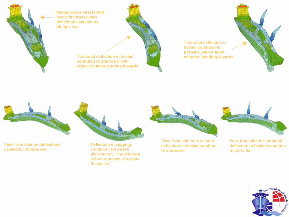
Multipurpose vessel with heavy lift cranes with deflections caused by oblique sea
Torsional deflection in heeled condition to starboard with crane columns bending inwards
Torsional deflection in heeled condition to portside, with cranes columns bending inwards
View from side on deflections caused by oblique sea
Deflection in sagging condition. No stress distribution. The different colors represent the plate thickness
View from side for torsional deflection in heeled condition to starboard
View from side for torsional deflection in heeled condition to portside

4. Local Stresses
4.1 Panting Stresses
These occur in the fore-ship during pitching. The constantly changing water pressure increases the stress in the skin and the frames. Panting stress is not a result of hydrostatic pressure, but more a result of hydrodynamic pressure. To reduce the panting stress effect, panting beams in transverse direction and stringers against the ship's shell are added to the forepeak, the area aft of the forepeak and aft peak structure.
4.2 PoundingWhen pitching becomes so heavy that the entire bow comes above the water, pounding or slamming can occur. Especially with a flat fore ship, such as in bulkcarriers and tankers, the dynamic forces on the flat bottom when that flat bottom beats at the sea- surface, can result in damage to plating and internals. Plates can be set in, and internals can be deformed.To prevent this kind of damage, thicker plates are fitted, and more internals, at smaller distances, such as floors at every frame, and more keelsons.
4.3 Diagonal loadsThese occur when the ship is asymmetrically laden and during rolling of the ship in waves. The effect of the diagonal loads is reduced by the addition of frame brackets, deck beam brackets, cross frames and transverse bulkheads.
4.4 Vibration StressThese can be caused by:-vibrations induced by the (main) engine,-forces on the aft ship caused by the rotation of the propeller.-wave impactVibration of a construction occurs when the own resonance frequency is equal to the first, second or third order of an induction source: the main engine, the propeller, etc. Adding weight and structure, and so changing the resonance frequency or local stiffening are remedies. Vibration is a growing concern, as ships are being built lighter and lighter, due to the use of high tensile steel, which allows thinner construction at the same strength, and the application of better paints, which eliminates the need of corrosion surplus. Vibration can result in fatigue-defects, noise, and discomfort for the crew.Vibration can also be eliminated by inducing another vibration source, with contra-pulses
4.5 Drydocking LoadsThese forces are the result of vertical upward forces in way of the location of keel and (to a lesser extent) the side blocks.Keelblocks are supposed to take the total weight of the ship. Side blocks are put in drydock to keep the ship upright, but of course also to take weight. When calculating block loads, only the keelblocks are taken into consideration.
5. Stiffening
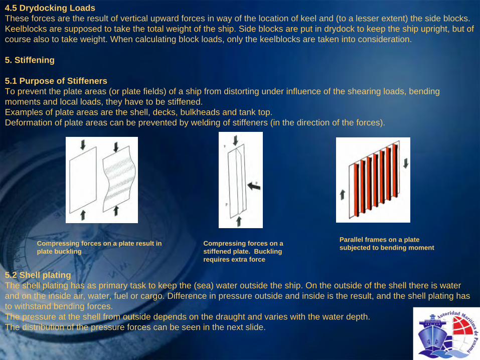
5.1 Purpose of StiffenersTo prevent the plate areas (or plate fields) of a ship from distorting under influence of the shearing loads, bending moments and local loads, they have to be stiffened.Examples of plate areas are the shell, decks, bulkheads and tank top.Deformation of plate areas can be prevented by welding of stiffeners (in the direction of the forces).
Compressing forces on a plate result in plate buckling
Compressing forces on a stiffened plate. Buckling requires extra force
Parallel frames on a plate subjected to bending moment
5.2 Shell platingThe shell plating has as primary task to keep the (sea) water outside the ship. On the outside of the shell there is water and on the inside air, water, fuel or cargo. Difference in pressure outside and inside is the result, and the shell plating has to withstand bending forces.The pressure at the shell from outside depends on the draught and varies with the water depth.The distribution of the pressure forces can be seen in the next slide.
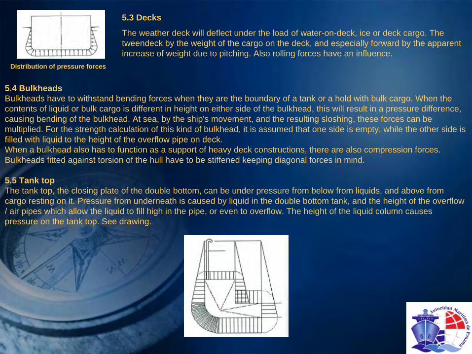
Distribution of pressure forces
5.3 Decks
The weather deck will deflect under the load of water-on-deck, ice or deck cargo. The tweendeck by the weight of the cargo on the deck, and especially forward by the apparent increase of weight due to pitching. Also rolling forces have an influence.
5.4 BulkheadsBulkheads have to withstand bending forces when they are the boundary of a tank or a hold with bulk cargo. When the contents of liquid or bulk cargo is different in height on either side of the bulkhead, this will result in a pressure difference, causing bending of the bulkhead. At sea, by the ship's movement, and the resulting sloshing, these forces can be multiplied. For the strength calculation of this kind of bulkhead, it is assumed that one side is empty, while the other side is filled with liquid to the height of the overflow pipe on deck.When a bulkhead also has to function as a support of heavy deck constructions, there are also compression forces. Bulkheads fitted against torsion of the hull have to be stiffened keeping diagonal forces in mind.
5.5 Tank topThe tank top, the closing plate of the double bottom, can be under pressure from below from liquids, and above from cargo resting on it. Pressure from underneath is caused by liquid in the double bottom tank, and the height of the overflow / air pipes which allow the liquid to fill high in the pipe, or even to overflow. The height of the liquid column causes pressure on the tank top. See drawing.

5.6 PanelThe water pressure results in forces on the plating, which is so large that they cannot be absorbed by the plate without deformation or even fracturing. The plates have therefore to be stiffened by stiffening profiles. A combination of plate with stiffeners is called a panel.By adding stiffeners, the panel is divided in strakes, with the width of the stiffener-spacing. The load on that area is transferred to the stiffener, which in itself has gained in strength, due to the fact that it is welded to the plate. The thickness of the plating is determined by the stiffener spacing. In bulkheads; therefore, the lower plates are thicker than the upper plates. Classification gives regulations for the maximum spacing of stiffeners, depending on their function (shell frames).
Each stiffener takes its part of the total force working on a panel. The magnitude of the force is related to the pressure on the panel, the spacing of the stiffeners and the (unsupported) length of the stiffener. In the drawing below a panel is shown where the part supported by the middle stiffener has been indicated.To determine the dimensions of the stiffener, the width of the plate carried by the stiffener, is taken (for a certain percentage) into the calculation of the required section modules. The section modulus comprises stiffener plus plate. The effective part of plate is called: contributing plate.
When the unsupported length (span) of a stiffener is so long, that this is resulting in very heavy stiffeners, the stiffeners themselves are getting support from even heavier stiffeners, the so-called stringers or web frames. The spacing of horizontal webs, the stringers (flats), increases from a small spacing at the bottom to a large spacing at the top of the bulkhead, in connection with the triangular liquid pressure on the bulkhead. We can then use the same (vertical) profile section over the full height of the bulkhead.
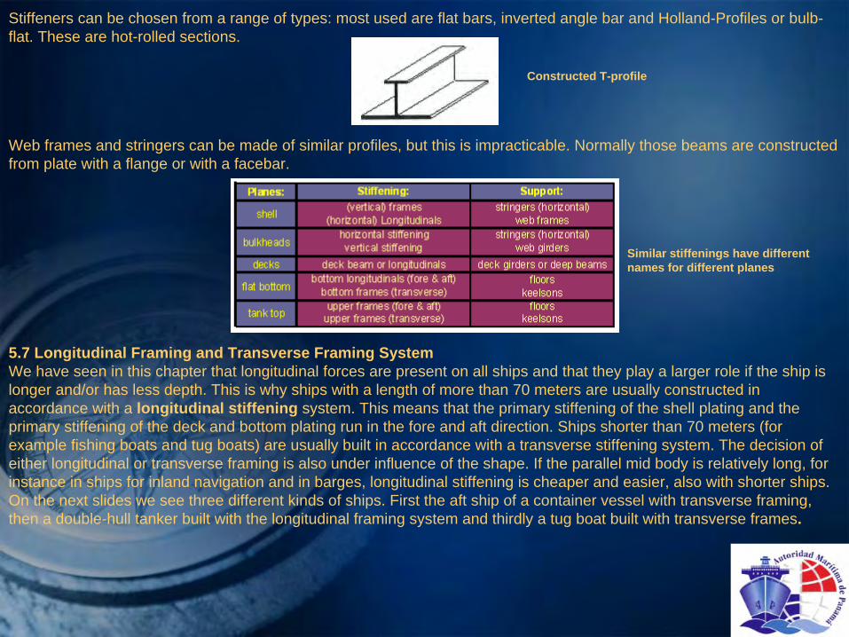
Stiffeners can be chosen from a range of types: most used are flat bars, inverted angle bar and Holland-Profiles or bulb- flat. These are hot-rolled sections.
Constructed T-profile
Web frames and stringers can be made of similar profiles, but this is impracticable. Normally those beams are constructed from plate with a flange or with a facebar.
Similar stiffenings have different names for different planes
5.7 Longitudinal Framing and Transverse Framing SystemWe have seen in this chapter that longitudinal forces are present on all ships and that they play a larger role if the ship is longer and/or has less depth. This is why ships with a length of more than 70 meters are usually constructed in accordance with a longitudinal stiffening system. This means that the primary stiffening of the shell plating and the primary stiffening of the deck and bottom plating run in the fore and aft direction. Ships shorter than 70 meters (for example fishing boats and tug boats) are usually built in accordance with a transverse stiffening system. The decision of either longitudinal or transverse framing is also under influence of the shape. If the parallel mid body is relatively long, for instance in ships for inland navigation and in barges, longitudinal stiffening is cheaper and easier, also with shorter ships.On the next slides we see three different kinds of ships. First the aft ship of a container vessel with transverse framing, then a double-hull tanker built with the longitudinal framing system and thirdly a tug boat built with transverse frames.

5
1. Frames2. Ice strengthening frames3. Web frames4. Deck beams5. Deck girders6. Centre keels (duct keel)
Cross-section of a container vessel near the engine room (transverse frames)
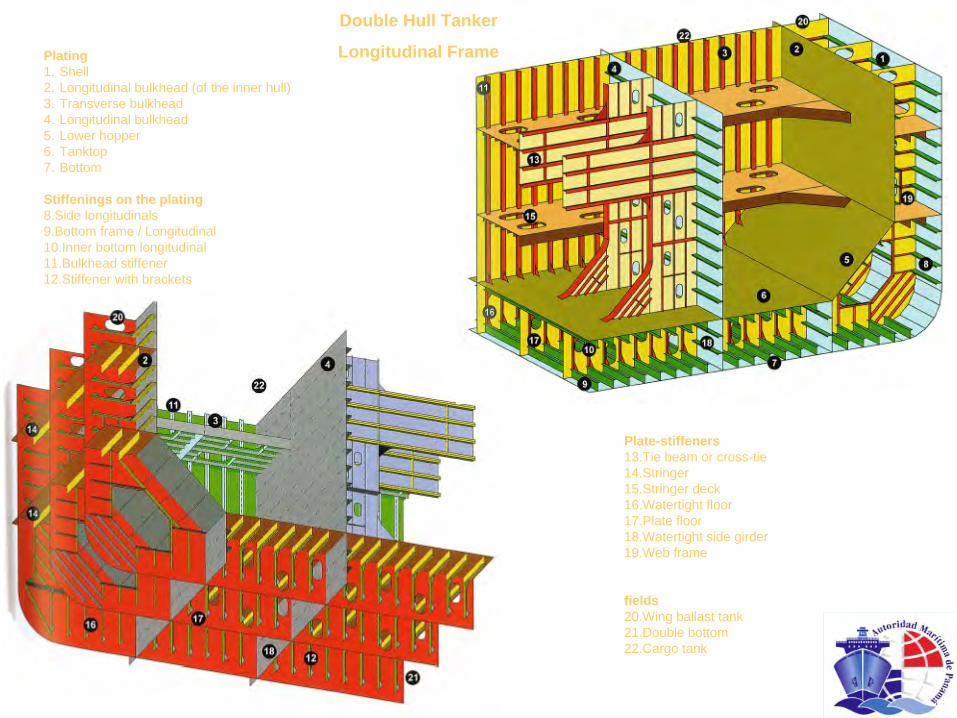
Plating1. Shell2. Longitudinal bulkhead (of the inner hull)3. Transverse bulkhead4. Longitudinal bulkhead5. Lower hopper6. Tanktop7. Bottom
Stiffenings on the plating8.Side longitudinals9.Bottom frame / Longitudinal10.Inner bottom longitudinal11.Bulkhead stiffener12.Stiffener with brackets
Plate-stiffeners13.Tie beam or cross-tie14.Stringer15.Stringer deck16.Watertight floor17.Plate floor18.Watertight side girder19.Web frame
fields20.Wing ballast tank21.Double bottom22.Cargo tank
Double Hull Tanker
Longitudinal Frame

Tugboat – Transverse frames
1 Wheelhouse front windows2 Wheelhouse rear windows3 Portside funnel4 Starboard side funnel5 Mast6 Deckhouse top7 Foredeck8 Forward bitts9 Forward bulwark with closed clock10 Location bow fender11 Side bollard forward12 Bilge keel13 Towing bitt14 Sideshell transverse frame15 Deck bracket16 Bilge bracket17 Transverse full floor18 Stringer19 Stern fender20 Sternroller, for anchor handling21 Bulwark toprail, gunwale22 Thruster nozzle23 Poop deck, working deck.24 Rubbing bar25 Deck beam26 Transverse bulkhead27 Location of towing winch28 Steering-gear room29 Side bollard aft30 Longitudinal bulkhead (Shaft tunnel)31 Bilge plating

Tugboat – Transverse frames
1 Wheelhouse front windows2 Wheelhouse rear windows3 Portside funnel4 Starboard side funnel5 Mast6 Deckhouse top7 Foredeck8 Forward bitts9 Forward bulwark with closed clock10 Location bow fender11 Side bollard forward12 Bilge keel13 Towing bitt14 Sideshell transverse frame15 Deck bracket16 Bilge bracket17 Transverse full floor18 Stringer19 Stern fender
27 Location of towing winch28 Steering-gear room29 Side bollard aft30 Longitudinal bulkhead (Shaft tunnel)31 Bilge plating
20 Sternroller, for anchor handling21 Bulwark toprail, gunwale22 Thruster nozzle23 Poop deck, working deck.24 Rubbing bar25 Deck beam26 Transverse bulkhead

Chapter 6 – Laws & Regulations1.The International Maritime Organization (IMO)
1.1 General
International shipping, and national shipping to a lesser extent, are subject to stringent laws and regulations, by international and national regulatory bodies.
Internationally those bodies are united in the international Maritime Organization, IMO.
Within the United Nations, maritime affairs are taken care of by the International Maritime Organization, in abbreviation, IMO. The main objective, from the first conference in 1948 up to its entry into force in 1958, is improvement of safety at sea. SOLAS (Safety Of Life At Sea) goes back as far as 1914, but due to World War I never came into force. There were even earlier international treaties, but they were not very successful.
Seafaring has, through history, always been one of the most dangerous occupations. Many countries had unilateral regulations on safety, but as sea trade is of international nature, the rules and regulations were better set up internationally, instead of by individual countries. In 1948 a conference was held where the basis was laid for IMO.
The slogan is: Safe, Secure and Efficient Shipping on Clean Oceans.The first objective was to improve safety of life at sea: SOLAS, followed by the subject of cleaner oceans, resulting in the
MARPOL Convention about marine pollution, accelerated by the Torrey Canyon accident (1967).

1.2 Assembly / CommitteesIn IMO the governing body is the Assembly, with has installed Committees for the different objectives.-MSC, the Marine Safety Committee, with safety related Conventions and Codes as their working area, resulting in the SOLAS Convention.-MEPC, the Marine Environment Protection Committee, with environmental subjects as their working area, resulting in the MARPOL regulations, first in 1973, afterwards 1978.
Other Committees are: LEGAL (Security), TCC (Training) and FAL (Electricity).There are some 10 sub-committees.Up to August 2008 there were 166 member states and three associated members.
Basic IMO structure
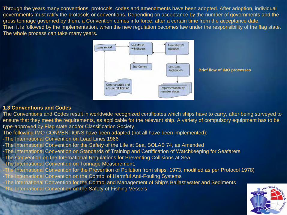
Through the years many conventions, protocols, codes and amendments have been adopted. After adoption, individual governments must ratify the protocols or conventions. Depending on acceptance by the number of governments and the gross tonnage governed by them, a Convention comes into force, after a certain time from the acceptance date.Then it is followed by the implementation, when the new regulation becomes law under the responsibility of the flag state. The whole process can take many years.
Brief flow of IMO processes
1.3 Conventions and CodesThe Conventions and Codes result in worldwide recognized certificates which ships have to carry, after being surveyed to ensure that they meet the requirements, as applicable for the relevant ship. A variety of compulsory equipment has to be type-approved by Flag state and/or Classification Society.The following IMO CONVENTIONS have been adapted (not all have been implemented):-The International Convention on Load Lines 1966-The International Convention for the Safety of the Life at Sea, SOLAS 74, as Amended-The International Convention on Standards of Training and Certification of Watchkeeping for Seafarers-The Convention on the International Regulations for Preventing Collisions at Sea-The International Convention on Tonnage Measurement,-The International Convention for the Prevention of Pollution from ships, 1973, modified as per Protocol 1978)-The International Convention on the Control of Harmful Anti-Fouling Systems-The international Convention for the Control and Management of Ship's Ballast water and Sediments-The International Convention on the Safety of Fishing Vessels

Each of the Conventions is, where necessary, more precise in Codes. However, some Codes are independent, without reflection to a Convention.
Examples of CODES:- The IMO Code for the Construction and the Equipment of Ships Carrying Dangerous Chemicals in Bulk,- The ILO/IMO Code of Practice on Security in Ports- The IMO Code of Safe Practice for Solid Bulk Cargoes (BS Code)- The International Safety Management Code (ISM)- The IMO Code of Safe Practice for Ships Carrying Liquefied Gases in Bulk- The FAO/ILO/IMO Code of Safety for Fishermen- The IMO Code of Safe Practice for Cargo Stowage- The IMO Code of Practice for Atmospheric Oil Mist Detectors- The IMO Code of Practice for the Safe Carriage of Irradiated Nuclear Fuel- The IMO International Code of Signals- The IMO Code of Equipment of Mobile Offshore Drilling Units (the MODU Code)
2. CertificatesBefore any Certificate can be issued, a ship must be registered in a certain country, the Flag State. This means that the
flag state accepts a ship as carrying their flag and belonging to their 'fleet’. Against a certain fee, and taxation on the earnings, the authorities allow the ship to sail under their jurisdiction. The port and country where the ship has been registered has to be mark on the stern.
The certificates can be divided in certificates every ship must have on board, and certificates which are connected to the type of cargo the ship is intended for, or the area the ship is allowed to sail.
2.1 Compulsory Certificates in accordance with SOLASThe SOLAS Convention requires every ship on international voyages (above 500 GT) to have on board:
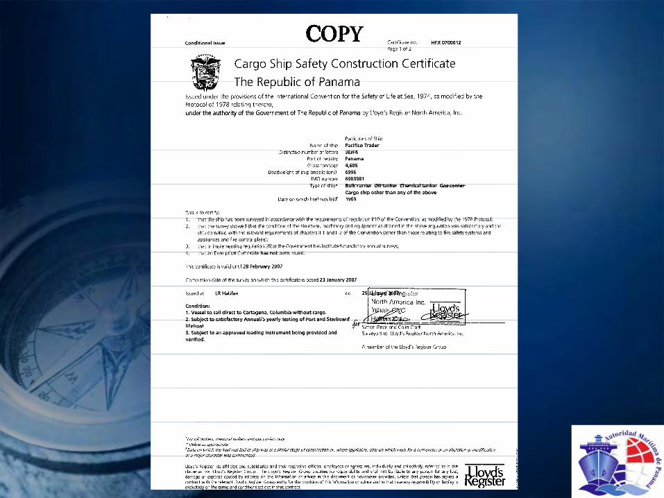
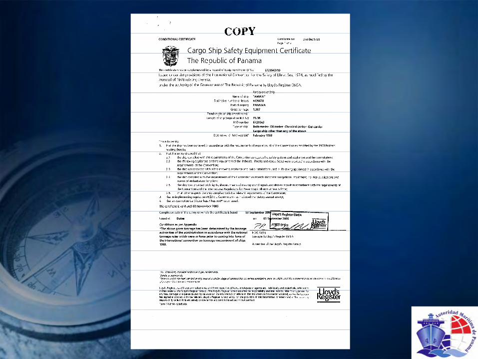
On cargo ships:1.Cargo Ship Safety Construction Certificate2.Cargo Ship Safety Equipment Certificate3.Cargo Ship Safety Radio CertificateA Cargo Ship Safety Certificate, combining I, 2 and 3.These can be issued to replace 1, 2 and 3 above. All above certificates have to be accompanied by a.

Record of Equipment, giving a list of items which need to be on board of the relevant ship.In SOLAS the ship's construction is also regulated, with regards to strength, maximum size of floodable compartments, intact and damage stability, covered under the Safety Construction Certificate.
On Passenger ships:—Passenger Ship Safety CertificateEarlier in use than the cargo ship safety certificate, the passenger ship safety certificate with the same content.Rules and regulations and certificates are more stringent for passenger ships than for cargo ships.
2.2 Certificates, compulsory in accordance with other Conventions:
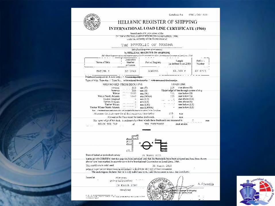
2.2.1 LoadlineThe Loadline Convention requires the International Loadline Certificate, evidence of meeting freeboard requirements, as prescribed in the Convention, and in the relevant Code. Loadline requirements started in the United Kingdom by a member of parliament, Mr Plimsoll, after which certificates have been issued by the Classification Societies since 1876, when the Freeboard Mark or Pliensoll Mark became compulsory. The regulations to comply with at present are laid down in the Loadline Convention 1966. On the basis of ship's length, size of openings in deck, sheer, door sill heights etc., a minimum freeboard is calculated, and has to be displayed at the ship's side. The carriage of timber as deck-cargo, or oil in an oil tanker, gives relaxations. The Plimsoll Mark shows minimum freeboard, and is a safety mark.
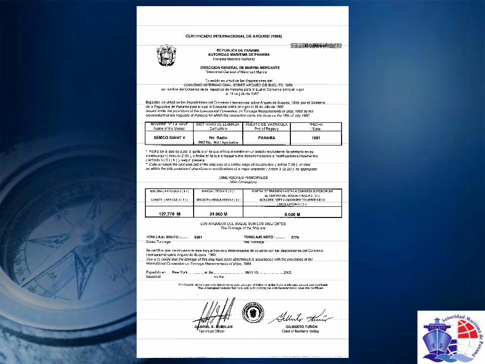
2.2.2 TonnageThe Tonnage Convention requires every ship to be provided with The International Tonnage Certificate. As proof of the registration the Flag state issues this certificate, or the Classification Society issues this certificate on their behalf. This certificate is worldwide accepted as giving the official details of the ship: main dimensions and volumes of the various spaces, in particular the spaces in connection with cargo, cargo holds, tanks, etc., all in accordance with regulations set out in the Tonnage Convention.It shows Gross Tonnage and Net Tonnage, figures with a high legal value. Net Tonnage is the Gross Tonnage minus the spaces which do not directly contribute to the earnings, like ballast tanks and the engine room for a certain percentage. Details can be found in the Convention. Harbor dues and many other financial charges are often based on GT.Every ship is provided with a so-called IMO number, a 7-digit number as an identification, the idea for the number borrowed from Lloyd's Register. The number stays with the ship for its lifetime, and has to be marked off clearly visible, and is printed on all certificates
Apart from the international Tonnage Certificate, the Suez Canal and the Panama Canal have their own way of establishing 'tonnage' to base their fees on. Therefore, special tonnage certificates are issued for Suez Canal and Panama Canal.
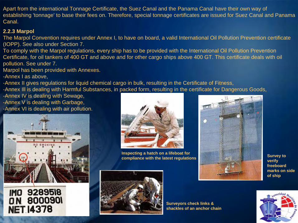
2.2.3 MarpolThe Marpol Convention requires under Annex I, to have on board, a valid International Oil Pollution Prevention certificate (IOPP). See also under Section 7.To comply with the Marpol regulations, every ship has to be provided with the International Oil Pollution Prevention Certificate, for oil tankers of 400 GT and above and for other cargo ships above 400 GT. This certificate deals with oil pollution. See under 7.Marpol has been provided with Annexes.-Annex I as above,-Annex II gives regulations for liquid chemical cargo in bulk, resulting in the Certificate of Fitness,-Annex Ill is dealing with Harmful Substances, in packed form, resulting in the certificate for Dangerous Goods,-Annex IV is dealing with Sewage,-Annex V is dealing with Garbage,-Annex VI is dealing with air pollution.
Inspecting a hatch on a lifeboat for compliance with the latest regulations Survey to
verify freeboard marks on side of ship
Surveyors check links & shackles of an anchor chain
2.3 Examples of Certificates in connection with the ship’s designation:
2.3.1 Dangerous Goods
International Certificate of Fitness for the Carriage of Dangerous Chemicals in Bulk (IBC Code Certificate) accompanied by a cargo list, is issued when the ship is found applicable to the regulations in the relevant Code. A chemical tanker has to be provided with equipment to minimize residues in cargo tanks, various measurement tools and special equipment related to the cargo they are intended to transport. The cargo list gives the names of the chemicals the tanks comply with. This relates to closing appliances, cargo tank coating, gasket materials, protective clothing, breathing apparatuses, gasmasks, etc.
2.3.2 Certificate of Fitness for the Carriage of Liquefied Gases in Bulk
Gas ships have a similar Certificate of fitness for the Carriage of liquefied Gases in Bulk, in accordance with the International Gas Code, or for older ships the Gas Carrier Code.
2.3.3 Certificate of Compliance for the Carriage of Dangerous GoodsThe carriage of dangerous goods in all forms: packaged form, in solid form in bulk, explosives, dangerous liquid chemical cargoes in bulk in chemical tankers, gases in gas tankers and packed radio-active materials, is regulated in SOLAS Chapter VII. In the subdivisions A-D all kinds of rules and provisions are given, withrequirements for the ship's construction, stowage requirements and packing, labeling, etc.On the certificate is clearly stated which dangerous goods the ship is allowed to carry. An approval cargo list gives the specific names.
2.3.4 Certificate of Compliance for the Carriage of Solid Bulk CargoesFor bulk carriers a special certificate has been created in connection with the transport of Solid Bulk Cargoes. These cargoes have been categorized A, B and C, depending on their hazards. A is the least harmful, C the most harmful. For each of these cargoes there are special requirements.
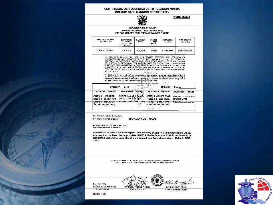
2.3.5 Minimum Safe Manning Certificate
The Flag state is also responsible for stating the minimum number of crew, and their required qualifications, who have to be on board when the ship is underway.

3. ClassificationShips are built in accordance with Rules and Regulations of a Classification Society, chosen by the prospective owner. The Society approves the relevant drawings, and inspects the actual construction. Classification is controlling strength and quality of materials and workmanship in connection with the ship, when built "under Class*.The Classification Society issues a certificate upon completion of construction:The Certificate of Class, for Hull and Machinery.The Certificate of Class is the basis for underwriters to insure a ship.At the same time a trading Certificate of Class is issued with a validity of 5 years which has to be endorsed every year, on completion of the Annual Survey.Every year, in a window of three months before the birthday and three months after, an Annual Survey has to be carried out, covering Class, Safety Construction, Safety Equipment, Loadline, Radio, Marpol, Fitness, Dangerous Goods, Cargo gear, etc. Normally all done at the same port of call as far as practicable.When at the end of the three months after the 'birthday‘ one of the trading certificates has not been endorsed by the relevant Classification or Flag state the ship is not allowed to leave port.To carry out the different surveys, the Class Societies each maintain a worldwide network of surveyors, centralized by their main offices.The main Societies have been since 1968 grouped under IACS, the International Association of Classification Societies. Since 1970 they are consultative to IMO, contributing their expert technical knowledge.The members are (in alphabetic order):-American Bureau of Shipping (ABS) -Korean Register (KR) Associate:-Bureau Veritas (BV) -Lloyd's Register (LR) Indian Register of Shipping (IRS)-China Classification Society (CCS) -Nippon Kaiji Kyokai (NK)-Det Norske Veritas (DNV) -Registro Italiano Navale (RINA)-Gemanischer Lloyd (GL) -Russian Maritime Register of Shipping (RS)
The division between Classification certificates and statutory certificates is as follows:-The Classification Society looks after the technical condition of the ship.-The Flag State (country of Registry) after the people on board, and their behavior in connection with safety, environment and communication.
Panama also recognizes a group of private companies acting on its behalf for the issuance of statutory certificates known as Recognized Organizations (RO). Visit our website (www.segumar.com) for a complete list.
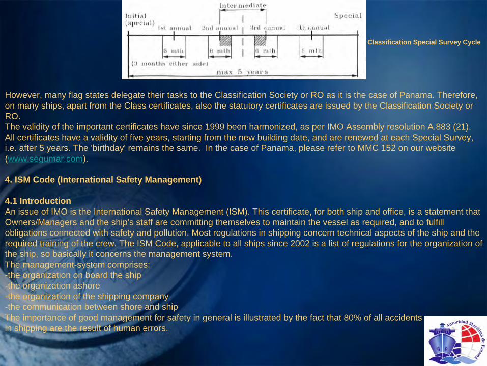
Classification Special Survey Cycle
However, many flag states delegate their tasks to the Classification Society or RO as it is the case of Panama. Therefore, on many ships, apart from the Class certificates, also the statutory certificates are issued by the Classification Society or RO.The validity of the important certificates have since 1999 been harmonized, as per IMO Assembly resolution A.883 (21). All certificates have a validity of five years, starting from the new building date, and are renewed at each Special Survey, i.e. after 5 years. The 'birthday' remains the same. In the case of Panama, please refer to MMC 152 on our website (www.segumar.com).
4. ISM Code (International Safety Management)
4.1 IntroductionAn issue of IMO is the International Safety Management (ISM). This certificate, for both ship and office, is a statement that Owners/Managers and the ship's staff are committing themselves to maintain the vessel as required, and to fulfill obligations connected with safety and pollution. Most regulations in shipping concern technical aspects of the ship and the required training of the crew. The ISM Code, applicable to all ships since 2002 is a list of regulations for the organization of the ship, so basically it concerns the management system.The management-system comprises:-the organization on board the ship-the organization ashore-the organization of the shipping company-the communication between shore and shipThe importance of good management for safety in general is illustrated by the fact that 80% of all accidentsin shipping are the result of human errors.
4.2 ObjectivesThe objectives of the ISM Code are: - to satisfy all relevant national and international regulations like SOLAS. MARPOL, ISM, Class and Labor laws- creating a permanent awareness of safe behavior by the personnel on board and ashore- ensuring a readiness to act effectively in emergencies- guaranteeing safety at sea- preventing accidents and damage to environmentThe ISM Code is a standard of safety consisting of 13 elements, each describing a business operation that is relevant to
safety and environment. The elements can be considered as paragraphs of the ISM Code. They can deal with:- (planned) maintenance- office personnel and crew
4.3 How ISM worksa.The Shipping CompaniesEvery shipping company must possess a Document of Compliance (DOC). This document states that the shipping
company is found fit to exploit the ship in accordance with the demands of the ISM Code. One of the demands is that the shipping companies must develop, execute and maintain a Safety Management System (SMS).
The Flag state issues the DOC, but only after a Classification Society has approved the safety management system. The DOC remains valid for a period of five years, provided that the annual surveys by the Classification Society yield good results.
b. The ShipsThe ships can get a Safely Management Certificate (SMC) if the DOC has been issued to the shipping company. The
SMC also remains valid for a five year period. During this period there should be an inspection between the second and third years.
4.4 The AuditsThe SMS is inspected by means of an audit. An audit is a prescribed survey to check whether the organizations on shore
and on the ship are able to successfully execute the regulations and have reached certain goals. Audits can be distinguished into internal audits and external audits.
The ISO organization grants one certificate to the entire organization, contrary to the ISM which has separate certificates for the organization on and off shore.

a.Internal AuditsInternal audits are performed by the shipping company and can comprise matters like:- the overlap between the way of working on board and the SMS regulations applied- checking if the measures taken for safety and the environment are in accordance with the SMS- testing the SMS for efficiency and taking measures if necessaryAll relevant personnel must be informed of the results of these audits and the measures taken. The management must
correct all shortcomings. Internal audits are usually performed annually.
b. External AuditsExternal audits are performed by the bureau of classification under supervision of the Flag state. if the organization lives
up to the standards set, the shore organization receives the DOC and the ship the SMC.
5. International Organization for Standardization (ISO)ISO has drawn up the:- ISO 9000 (standard)- ISO 14000(owinmment)- ISO 18000(labor circumstances) These standard set demands for matters that an organization should have or do in such a way that the customer can be
confident that the product meets the standards of good quality.A company will voluntarily use the ISO standards, possibly under pressure of the free market. The company will draw up a
Quality Management System (QMS) that can be certified by a bureau of classification.The IS0 9000 standard is a general standard aligned to the ISM Code. This means that every company draws up and
executes its own QMS based on the demands.
6. ISPS CodeBy various regulatory bodies, measures have been taken in connection with the growing threat of terrorist attacks. IMO
has compiled regulations under the name:International Ship and Port Facility Security Code (ISPS Code).Applicable to:- Passenger ships- Cargo ships above 500 GT- Mobile Offshore Drilling Units- Harbor Facilities, and means of transport.
Above ships need to have on board an International Ship Security Certificate. Fishing ships and Navy ships are exempted from the Code.
Objective of the ISPS Code is that risk of a terrorist activity is minimized."Security officers" have to be appointed:-Company Security Officer (CSO)-On a ship the Ship Security Officer (SSO)-On a harbor facility the Port Facility Security Officer (PFSO)All ships which are obliged to carry an ISPS certificate, and the relevant harbor facilities have to compile a security scheme, comprising all security measures, such as:-To know at each moment who are on board or on the facility-To control entrances and perform visitor identity checks-To control loading and discharging cargo and stores.
The ISPS Code acknowledges 3 threat levels:-level 1: No specific threat - no additional measurements needed,-level 2: Enhanced, general threat - increased security-level 3: Terrorist threat - further increased measures.
7. Marine Pollution (MARPOL)In 1973 IMO adopted the International Convention for the Prevention of Pollution from Ships, modified again in 1978. The Marine Environment Protection Committee (MEPC) does the daily work and has given clarification. The actual regulations to prevent pollution by environment unfriendly substances are given in "Annexes".The following applies to ships. For platforms and other stationary equipment at sea, other regulations apply, also specified under Marpol.Note: On January I, 2007, a updated and revised Annex I came into force.
7.1 Annex IThis Annex of Marpol deals with regulations in order to prevent the pollution of the seas by oil from ships. Oil is defined for this Annex as petroleum in any form including crude oil, fuel oil, sludge, oil refuse and refined products. All such substances are listed in the appendix 1 to this Annex.We have two basic situations:- Oil and oily mixtures generated in the Engine Rooms of a ship not being an oil tanker of 400 GT and
above, and engine rooms of any oil tanker.- Oil and oily mixtures resulting from cargo pump rooms, cargo handling, cargo tank cleaning, etc. on Oil Tankers.
All Engine Rooms generate waste oil, sludge and oil polluted bilge water. Waste oil and sludge will be collected in waste oil tanks and sludge tanks, and the bilge water via the bilge wells, in bilge water holding tanks. After settling, the water in the bilge water holding tank can be pumped into the sea, under the following conditions:-the oil and oily-mixture is not mixed with cargo residues-is not coming from cargo pump rooms-the vessel is not in a Special Area-the vessel is underway at sea-the oil content of the effluent without dilution does not exceed 15 parts per million (PPM), and the ship has in operation a filtering equipment as required by regulation 16 of the Annex.
To be allowed to discharge oil and oily mixtures from engine rooms while sailing in a Special Area, there must be a filtering equipment on board, with an oil content meter, and a device that automatically stops the discharge when the oil content exceeds 15 PPM.This oil content meter and stopping device is already a requirement for vessels larger than 10,000 GT. If a vessel of less than 10,000 GT wishes to discharge in a Special Area, it also must be equipped with an oil content meter and an automatic stopping device.The content of the bilge holding tank is pumped to a bilge separator. This is a vertical settling tank, where the oil separates from the water, often followed by a filter which filters the remaining oil (if any) out. In the settling lank, a probe measures if oil is found, and starts a pump, discharging the oil to the waste oil tank. When the probe does not find oil, the pump stops. The remaining water is pumped overboard via the oil content meter which checks via a full flow, or via a bypass flow the oil content in the processed bilge water. If the oil content is more than 15 PPM, a pre-alarm is generated, but the discharge is still not stopped. If the oil content is consistent over 15 PPM, after ± 20 seconds a second alarm is generated. This second alarm will stop the discharge.The automatic stopping device can be a three-way valve, a combination of two alternating working valves, or a pump stop. The automatic stopping device must be so arranged, that in case of a failure or in power-off condition, no discharge into the sea is possible.All the equipment must be Type Approved. and kept well maintained.

All operations like fuel bunkering, transfer of waste oils and sludge, handling of bilge water, defects on the filtering equipment, accidental discharges must be recorded without hesitation in the Oil Record Book.The Special Areas can be found in regulation 10 of the Annex. The North-West European Waters, the Baltic Sea and the Mediterranean are Special Areas, to give some examples.Oil Tankers generate cargo residues, remains from cargo line blowing, manifold-drip trays, tank washings, pump room bilge water, etc. Those oily residues are collected in the slop tank(s) of the vessel. It is under no condition allowed to transfer such oily residues to the engine room.Oil Tankers have apart from the engine room generated oils, another problem. When an oil cargo is discharged, there is always residue, and often the tanks must be cleaned to prepare them for a next cargo.Washing is done with rotating water jets in the tanks, generating an oily water mixture which is pumped to the so-called slop tank. There it is left to settle into oil and water.Tank washing is performed using tank washing machines. These machines are water pressure driven, and give rotating water jets, which reach every corner of the surface of the tank. While washing, the washing water is continuously pumped to another tank or the slop tank.Water washing is carried out to enable tank entry. To achieve a gas free condition, all the oil which can generate gas, needs to be away. This is best done by washing the tank. After washing and pumping away the slops, the tank is to be properly re-inerted, after which the tank has to be ventilated, till the oxygen content is 21%. By following this procedure, there is never an explosive mixture.After settling, it is allowed to pump the contents of the slop tank into the sea, under the following conditions:-the tanker is not within a Special Area,-the tanker is more than 50 nautical miles from the nearest land,-the ship is underway at sea-the instantaneous rate of discharge of oil content does not exceed 30 liters per nautical mile,-the total quantity of oil discharged into the sea does not exceed:-for existing tankers 1/15,000 of the total of the particular cargo of which the residue formed a part,-for new tankers 1/30,000 of the total quantity of the particular cargo of which the residue formed a part.-the tanker has in operation Oil Discharge and Monitoring Equipment and a slop tank arrangement as required by regulation 15 of this Annex.The Oil Discharge and Monitoring Equipment (ODME) must be type approved. Oil tankers over 150 GT must be equipped with an ODME.All operations must be recorded in the Oil. Record Book without hesitation.The remaining oil is to be retained in the slop tank. Either to be pumped ashore later, or when the next cargo is suitable, usually only possible with crude, to be mixed with that next cargo. (load-on-top-system). If this is not allowed, the content of the slop tank has to be pumped ashore, at a reception facility.
Crude tankers during discharge wash their tanks with cargo, to prevent the accumulation of sediment. The cargo oil is pumped through the rotating jets with high pressure, and the sediments are kept mixed with the cargo and pumped ashore with the cargo. This is called Crude Oil Washing (COW). The rotating jets are the same as used during tank washing.A problem connected with high pressure water washing and COW is that static electricity is generated. Crude Oil Washing (and water washing) is therefore only allowed at an atmosphere with reduced oxygen (5%), below the level that explosions or fire can occur. COW is compulsory through Marpol legislation, and lnert Gas is a consequence. To achieve an atmosphere above the cargo, or in the empty tank of below 5% oxygen, the exhaust gas of the boiler is, after washing, led into the tank during discharging.All tankers need their cargo and ballast water to be kept in completely separate tanks. These are called Segregated Ballast Tanks (SBT). All handling of oils and ballast water has to be accurately administrated and entries are to be kept on board for three years.The minimum SBT capacity of a tanker is regulated to ensure sufficient ballast capacity for safe navigation.
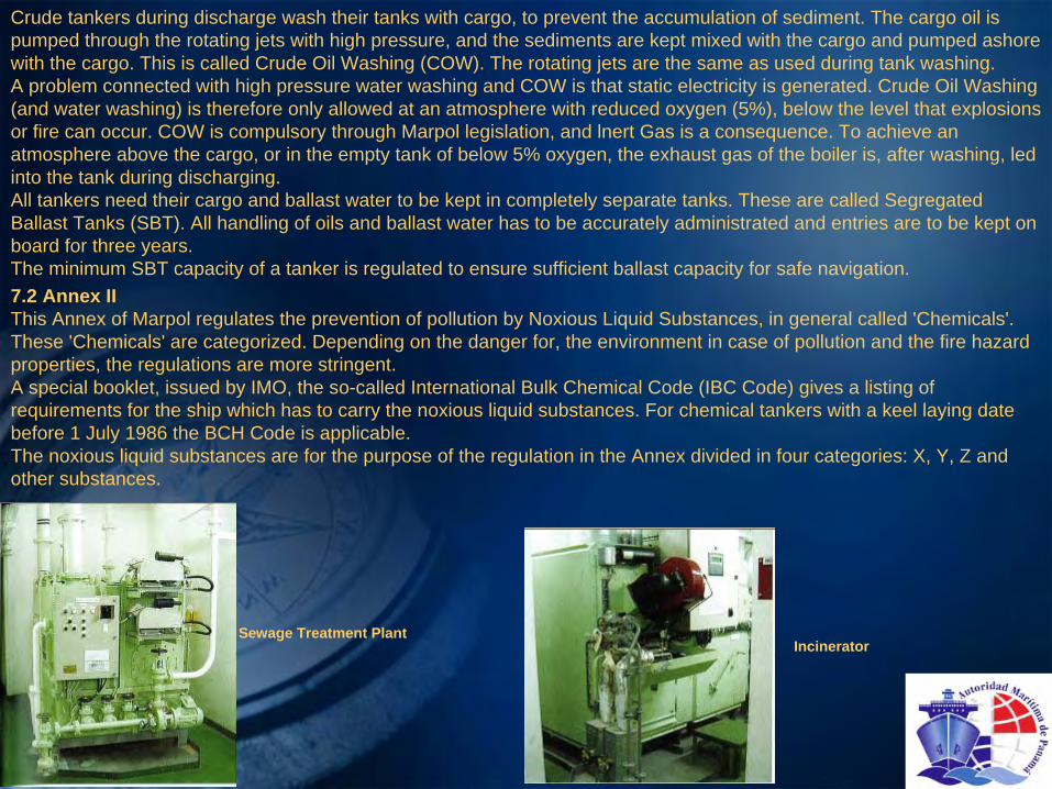
Sewage Treatment PlantIncinerator
7.2 Annex IIThis Annex of Marpol regulates the prevention of pollution by Noxious Liquid Substances, in general called 'Chemicals'. These 'Chemicals' are categorized. Depending on the danger for, the environment in case of pollution and the fire hazard properties, the regulations are more stringent.A special booklet, issued by IMO, the so-called International Bulk Chemical Code (IBC Code) gives a listing of requirements for the ship which has to carry the noxious liquid substances. For chemical tankers with a keel laying date before 1 July 1986 the BCH Code is applicable.The noxious liquid substances are for the purpose of the regulation in the Annex divided in four categories: X, Y, Z and other substances.

Category X is the most toxic one, and category other substances practically non-toxic; when discharged into the sea from tank cleaning or de-ballasting operations they would be a major hazard (cat. X) up to a recognizable hazard (other substances) to either marine resources or human health.Depending on the cargo category, the ship's cargo tanks have to meet special requirements, with regard to location, distance from ship's side or bottom, i.e. double hull requirements. Therefore the ships are divided into 'types I, II and Ill.Pumping, piping and unloading arrangements are regulated. Slop handling and mandatory pre-wash (cleaning and discharge of the tank washings ashore after unloading) are prescribed.Stability in intact and damaged condition is an important issue.Another important requirement for all chemical tankers is the total quantity of residue on board after discharging. Special cargo pumps, or built-in devices in the cargo pumps allow emptying of the tanks till only a minor quantity (some liters per tank) is left behind; this is called the minimum stripping quantity. Pumping the last drops out goes via a small pipe and not via the normal discharge line to the manifold.As with all other tankers, all cargo handling has to be accurately administrated in the Cargo Record Book, without delay. The relevant equipment required for chemicals, and the required procedures, are described in a specific book: The Procedures and Arrangements Manual.Each chemical tanker has to be provided with a International Certificate of Fitness for the Carriage of Dangerous Chemicals in Bulk, with a attached list of cargoes that the ship is fit to carry, a tank plan, tank groups, and a list of additional requirement. On BCH Code chemical tankers this certificate is called the Certificate of Fitness for the Carriage of Dangerous Chemicals in Bulk. This certificate has a validity of five years and runs parallel with the Special Survey cycle. Annual survey of the equipment is mandatory after which the certificate is endorsed.
7.3 Annex IIIThis Annex of Marpol regulates the carriage of Packed Harmful substances. The carriage of harmful substances is prohibited, except when in accordance with the provisions in this Annex. Packages have to be labeled with the correct name and durable mark or labeled as a marine pollutant.The packing must be adequate. There are stowage requirements and quantity limitations. Throwing overboard is only allowed in case the safety of the ship is at risk or in case of saving life at sea, This type of cargo is to be reported (type, quantity, location) to harbor authorities in each port the ship calls at, also when the cargo is not handled.The relevant certificate is called: Document of Compliance for the Carriage of Dangerous Goods.

Waste Management

7.4 Annex IVThis Annex regulates the Prevention of Pollution by Sewage, applicable to ships of over 400 GT. Every ship shall be equipped with a sewage treatment system, comminuting and disinfecting system, or a holding tank.
Two criteria:-When a ship has a treatment system sewage can be discharged-Ships having a comminuting system can discharge sewage outside 3 miles of the nearest land.The size of the holding tank depends on the ship's normal operating scheme, and there must be adequate connections for discharge into a reception facility. The content of the holding tank can be discharged overboard at least 12 miles from shore, and only at a moderate rate of speed of at least 4 knots.
7.5 Annex VThis Annex regulates the Prevention of Pollution by Garbage. Garbage means all kinds of victuals, domestic and operational waste, liable to be disposed of continuously or periodically, except substances defined under other Annexes.Disposal into the sea of plastics is always prohibited. This includes ropes, fishing nets, and plastic bags. Floating waste like dunnage, lining and packing material is allowed to be disposed of at least 25 miles from the nearest land. Food waste, paper, rags etc. at least 12 miles from shore. When the last is ground into small particles, max. 25 mm, 3 miles is sufficient.Ships operating in special areas have to comply with more strict discharge standards. On ships intended for long voyages waste from packages, i.e. wood, carton, plastics, etc. can be disposed of by burning it in an incinerator. This is a simple stove, where the waste is put into the fire-space, and where a simple gas-oil homer ignites the waste, and if necessary keeps it burning. The ashes may be disposed of in the sea.A ship must have a garbage management plan and a record must be kept, similarly to substances described under other Annexes.
7.6 Annex VIAnnex VI deals with air pollution caused by ships. This Annex came into force the 19th of May 2005. It restricts the emission of:-Substances which attack the ozone layer,-Nitrogen-Oxygen compounds NO(x)-Sulphur-Oxygen compounds SO(x).-Volatile Organic Compounds (VOC)-Exhaust of incinerators,
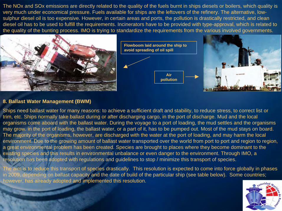
The NOx and SOx emissions are directly related to the quality of the fuels burnt in ships diesels or boilers, which quality is very much under economical pressure. Fuels available for ships are the leftovers of the refinery. The alternative, low- sulphur diesel oil is too expensive. However, in certain areas and ports, the pollution is drastically restricted, and clean diesel oil has to be used to fulfill the requirements. Incinerators have to be provided with type-approval, which is related to the quality of the bunting process. IMO is trying to standardize the requirements from the various involved governments.
Flowboom laid around the ship to avoid spreading of oil spill
Air pollution
8. Ballast Water Management (BWM)
Ships need ballast water for many reasons: to achieve a sufficient draft and stability, to reduce stress, to correct list or trim, etc. Ships normally take ballast during or after discharging cargo, in the port of discharge. Mud and the local organisms come aboard with the ballast water. During the voyage to a port of loading, the mud settles and the organisms may grow. in the port of loading, the ballast water, or a part of it, has to be pumped out. Most of the mud stays on board. The majority of the organisms, however, are discharged with the water at the port of loading, and may harm the local environment. Due to the growing amount of ballast water transported over the world from port to port and region to region, a great environmental problem has been created. Species are brought to places where they become dominant to the existing species and this results in environmental unbalance or even danger to the environment. Through IMO, a resolution has been adopted with regulations and guidelines to stop / minimize this transport of species.
The aim is to reduce this transport of species drastically. This resolution is expected to come into force globally in phases in 2009, depending on ballast capacity and the date of build of the particular ship (see table below). Some countries; however, has already adopted and implemented this resolution.
The subject has been divided in a sediment problem and the problem of organisms. The amount of mud has to be minimized by taking ballast in deep water, and by removing mud when it has settled. Getting rid of sediment is net easy. The best way is manually: use a fire hose with low pressure and high volume, hose the mud towards the suction of the ballast pump, and simultaneously pump the water with the mud overboard. This process is rather easy in large ballast tanks, but nearly impossible in low double bottom tanks, and very impracticable during a voyage.Apart from the environmental problem. the ship's loading capacity is reduced by the weight of the mud. This weight can vary front just a few tons in a small coastal vessel, up to 2000 tons in case of a capesize bulk carrier, or a large tanker. Therefore, the sediment content has to be monitored. The amount of sediment normally stabilizes, and is the main content of the 'ships constant'. This is the difference between what the ship should be able to load, and what it actually can load until the limits indicated by the freeboard requirements are reached.
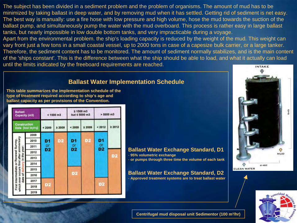
Ballast Water Implementation ScheduleThis table summarizes the implementation schedule of the type of treatment required according to ship’s age and ballast capacity as per provisions of the Convention.
Ballast Water Exchange Standard, D1- 95% volumetric exchange- or pumps through three time the volume of each tank
Ballast Water Exchange Standard, D2- Approved treatment systems are to treat ballast water
Centrifugal mud disposal unit Sedimentor (100 m³/hr)
Removal of sediment can be done in various ways. In the resolution disposal is allowed at sea at a minimum of 200 nm from shore and in water of minimal 200 meter depth. In port, or during repairs at a shipyard, disposal needs to be carried out at special reception fatalities.In order not to arrive in a loading port with the ballast water taken on board in the discharge port, the ballast has to be changed at sea during the voyage. Water taken in at 200 nm from shore and where the water depth is 200 meter or more, is considered 'clean'.Changing the ballast water can be performed in three ways which are acceptable to the IMO:I. Sequential method, emptying and refilling each individual tank,2. Flow-through method, replacing the water by adding to and simultaneously overflowing of the tank,3. Dilution method, filling over the top and simultaneously pumping water out the normal way.
A tank content is considered changed when 95 % of the water has been exchanged. When method 2 or 3 is chosen, changing is considered complete when three times the volume of the tank has been pumped through. During the whole procedure various topics are to be looked at:free surface effects, draught, trim, propeller immersion, minimal draught forward to prevent slamming, visibility from the bridge, stability, stress, sloshing, possible over-pressurizing, prevention of internal transfer of ballast water, etc.Changing ballast has to be planned, and has to be part of the voyage planning. Once started, it has to be completed, otherwise the organisms may grow again.
An approved Ballast Water Management Plan has to be on board every ship, explaining how to change ballast, and taking the above in account. A designated person in charge of ballast water management and responsible for the training of other personnel has to be appointed. The form of the plan and the record of BWM activities is stated in the IMO resolution. A Ballast Water Record Book has to be kept.
Where large gas tankers have fully automatic computer programs to run the pumping sequence, on small ships this still may have to be done manually. Precautions have to be taken that no contamination of water in already changed tanks with water from a tank that still has to be refilled when the pumping is changed from one tank to another.The quantity of organisms and mud can be reduced by not taking ballast during the night, when the organisms tend to come to the surface, in shallow water where propellers are stirring up the sediment or where dredging is in progress or recently done.
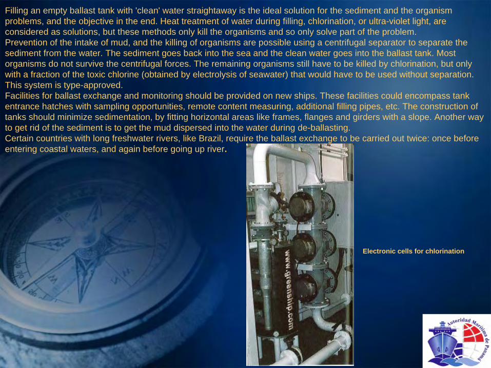
Filling an empty ballast tank with 'clean' water straightaway is the ideal solution for the sediment and the organism problems, and the objective in the end. Heat treatment of water during filling, chlorination, or ultra-violet light, are considered as solutions, but these methods only kill the organisms and so only solve part of the problem.Prevention of the intake of mud, and the killing of organisms are possible using a centrifugal separator to separate the sediment from the water. The sediment goes back into the sea and the clean water goes into the ballast tank. Most organisms do not survive the centrifugal forces. The remaining organisms still have to be killed by chlorination, but only with a fraction of the toxic chlorine (obtained by electrolysis of seawater) that would have to be used without separation. This system is type-approved.Facilities for ballast exchange and monitoring should be provided on new ships. These facilities could encompass tank entrance hatches with sampling opportunities, remote content measuring, additional filling pipes, etc. The construction of tanks should minimize sedimentation, by fitting horizontal areas like frames, flanges and girders with a slope. Another way to get rid of the sediment is to get the mud dispersed into the water during de-ballasting.Certain countries with long freshwater rivers, like Brazil, require the ballast exchange to be carried out twice: once before entering coastal waters, and again before going up river.
Electronic cells for chlorination
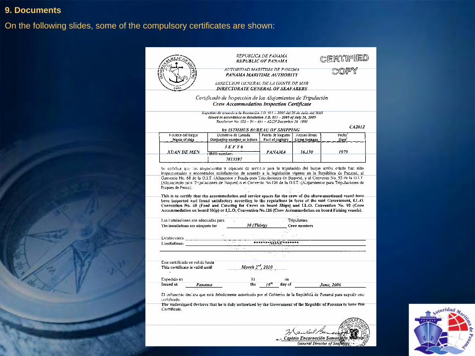
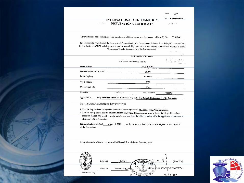
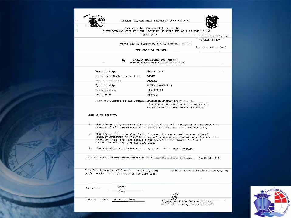
9. Documents
On the following slides, some of the compulsory certificates are shown:


THANK YOU!