module 5 introduction to basic standard knowledge for … course module/module 5.pdf ·...
TRANSCRIPT

PANAMA MARITIME AUTHORITYInternational Representative Office
New York, USA
MODULE 5
Introduction to basic standard knowledge for ASI Inspectors

INTRODUCTION•
This module is distributed with the sole purpose to provide basic standard ship knowledge to all ASI inspectors.
•
This material is intended for internal use of the Panama Maritime Authority only.
•
Panama Maritime Authority shall not be held liable from the unauthorized and illegal distribution, commercialization or modification from the original version and contents of this module.

Chapter 9 –
Cargo Gear/Lifting Appliances
1. Onboard Cargo Handling
Transshipment is moving cargo into and from a means of conveyance, like a ship or a truck. Most cargo is moved with the aid of some type of handling gear. Only very small and lightweight cargo is still moved by manpower. The cargo handling gear is either present on the ship (self-loader/ unloader) or at the port. ln
the latter case the quay has a large array of mobile cranes capable of moving along the length of the
quay. These cranes used to move exclusively on rails, but today an increasing number of cranes are equipped with ordinary wheels with air-tires and steering capabilities. This allows the cranes to move freely across the entire quay.
1.1 The Choice for on board Cargo Handling Gear
There are many types of cargo handling gear for ships and just as many incentives for choosing to install one or the other:-The charterer (who hires the ship) demands it. Although, is not the shipping company's concern, but if not in possession of a self-discharging ship, the order goes to a competitor who does have one!-The area of navigation demands it because the ports in that area lack cranes. This is often the case in some areas of Africa, South America, Asia and in small ports and factory sites
all over the world.-In order to transport special. cargo, too bulky or too heavy to handle with the available shore-cranes. This requires special attention, however, in general the earnings are higher.-Special cargo is a one time, large scale transport like a complete factory, moved in sections, or large and heavy machinery.

Ship's cranes reduce the stability and the
carrying capacity of a ship; they also cost money and require maintenance. On a general cargo ship, two cranes, including foundations, represent 10% of the total building costs. Refrigerated vessels often have 7 or more (light) cranes on board which may cost as mush as 20% of the total building costs. As a compromise it is possible that a ship is built without cranes, but with the
necessary foundation (strengthening in several places on the ship) and piping systems. if cranes are then required, they can be installed without radical changes to the ship and without extra loss of time (if the cranes are ordered in advance).
1.2 Statutory DemandsThe statutory demands for cargo handling gear, including lifts, ramps, hoistable
decks etc. are laid down in the ILO convention 152 (International Labor Organization). Compliance with the regulations is under the supervision of the Flag state and the Classification Society.Classification of cargo handling gear can be according to:-National law, which states that the ship checks the gear annually ands a class check is done every 5 years.-International regulations which state that the gear has to be checked annually by the Classification Society for an
Mobile crane on pneumatic tires Mobile crane loading paper rolls stacked on a pallet and handled by a forklift
Container cranes on rails at work
examination and a function test. Once in five years a Quadrennial Survey, i.e. a yearly examination, including opening up of blocks, etc . plus a load test.

Division of tasksThe inspections, certification and responsibilities are divided as follows:-AII ILO 152 tasks directly related to cargo handling (cranes, ramps etc.) are the responsibility of the Classification Society.-All ILO tasks related to safety, like entrance to the ship, hold
or crane entrances and safety in the holds as well as supervising the Classification Societies are the responsibility of the Flag state.-All tasks that do not result from the ILO 152 treaty like hoisting gear in the engine room, store cranes etc. are the responsibility of the shipping company, in compliance with national law and ISM.CertificatesThe items under control of the Classification Society are specifically mentioned in the Register of Ship's Lifting Appliances and Cargo Handling Gear.Excerpts from the ILO 152 treaty: Every seagoing vessel must have a Register of Ship's Lifting Appliances and Cargo Handling Gear.The inside cover of this register must state:-The rules for the five yearly insertions as stated in the ILO rules and the rules of the Classification Society.-Rules for the annual inspections-Test certificates must be present for all parts of the loading gear that can wear through use and ageing, like:
•the crane (complete)•the runner and topping lift wires•the blocks and sheaves•the hoisting winch•the crane hook•attachments
The certificate must show which requirements are applicable for every part.-
Certificates are marked by a name stamp of the surveyor, covered by his signature and the date and place of testing.-
The bottom of the jib must show:•the maximum safe working load (SWL).
Indication of SWL and range of a large shear legs floating crane
•the radius applicable to the load (the horizontal distance between turning point and vertical runner),These figures must be clearly visible from the place when the cargo is hooked on to the cargo hook.

2. Revolving CranesThe picture on the right shows a ship with three common revolving cranes. The crane house is bolted to a slewing bearing, which lower ring
is bolted to a pillar, the foundation, which is part of the ship's construction. The slewing bearing is a large double turning bearing. An electric or hydraulic motor grabs with its pinion in the rim of the upper turning ring, which is a large ring shaped cogwheel that rotates the crane. Normally the crane cannot rotate unrestrictedly in connection with electrical cables running to and from the crane, inside the pedestal.The crane cabin is a steel construction with windows that allow the crane driver a wide view of the area of activity. The wire drum, drive
engine and the controls and security are all located in the crane house. The diameter is 2-3 meters.The crane jib is hinged to the crane house, making lowering and topping possible. The crane jib consists of one or two box beams. The jib is designed in such a way that it has the desired strength, while its weight is minimal and its stiffness is maximal. The different types of revolving cranes that are discussed can be distinguished mainly on the basis of where the jib is attached to the crane house.
1. Crane foundation / pedestal
2. Slewing bearing
3. Crane house
4. Jib
5. Jib-crutch or boom rest
6. Topping cylinder
2.1 Position of Cranes on the shipMasts and cranes used to be placed exclusively on the centerline, but today they are increasingly moving towards the side of the ship.The following remarks can be made on this subject:-Positioning on the centerline of the ship is best for
the ship's stability. With cranes at centerline, the crane driver has a good view of the holds, but not of the quay. There is also no preference with which side the ship should come alongside.-If all the cranes are positioned on one side of the ship, there is an adverse effect on the position of the ship's centre of gravity. Therefore, only large, ships, where the mass of the cranes is very small compared to the ship's total mass, can have this kind of arrangement. For the crane driver the view of the holds is not so good compared to the situation where all the cranes are on the centerline, but the view on the quay is greatly enhanced. In addition, the reach of the crane on the quay is also much improved.

-An alternative is, to position one crane on port side and one on
starboard side, (or two and two, alternating). They are still off centre, but now half the number of cranes are not on the side of the quay, which is bad for the view and reach of these cranes.
-if remote controls (wireless) are used, the view from the crane cabin is of no importance. The crane driver can position himself wherever the view is the best.
2.2 Securing the craneAll crane jibs are subject to additional threes when the ship is
in waves. Therefore jibs have their own cradle, a support, where they can be secured during the voyage. This can be done in
several ways:-a fixed or moveable support, somewhere on the deck-a fixed support against the forecastle, a deck house, the poop deck-a neighboring crane as support if the crane jib's length equals the distance between the two cranes-a support against the crane cabin to which the jib can be fastened when the crane is not in use.
2.3 Load Control
a. Slewing velocityRevolving cranes often have a long cargo runner (hoisting wire) to which the load is attached, especially at short range
(when the jib is near vertical). If the crane rotates, the initial velocity of the load will be less than the velocity of the jib. The velocity of the load increases. When the jib has reached its
final position and stops there, the load will still have momentum, which sends it past the position of the jib. The skills of the crane driver make that the load arrives at the intended location.
An objection to the revolving crane is that the horizontal momentum of the load makes it difficult to accurately position the load. High loading and discharging speeds cannot be obtained therefore. In many cranes with a large range, the angular velocity, when revolving, is reduced automatically is connection with the following:
-
The forces of accelerating and decelerating increase with the square of the range.-
The centrifugal forces, which give the load the tendency to leave its circular trajectory, increase as a function of the crane's range.
-
Crane drivers can central the load up to a maximum angular velocity of 2.5-3 m/s.

b. Lifting Capacity
The maximum pulling capacity of a drum-winch is, an average of 10-25 tons. If the jib is lowered and the radius of the crane increases, the
load, hanging flaw the end of the jib, increases the moment on the crane (tipping moment). For this reason, the maximum load of all cranes depends on the radius (inversely proportional). In some cranes, the maximum pulling force of the winch is automatically reduced when the radius increases. This prevents that loads are lifted when the radius is too large. (load/ momentum-limit).
c. Lifting velocity
In some cranes it is possible to switch the winch manually from single work to double acting. In double acting, the maximum pulling force is
larger and the lifting velocity smaller (inversely proportional). Often this switching is automatic; if the crane has to lift a too heavy load it will switch to double work.
1. Support on deckhouse
2. Support on the fore mast
2.4 Ship’s StabilityWhen working with cargo gear, and especially with heavy loads, the stability (GM) of the ship must be positive to such an extent, that it remains positive when the load is suspended from
the crane. Ship's initial calculated stability allows cranes to cause a list of not mote than 5°. Too great a list can be prevented or reduced by shifting ballast water (or fuel). In many ships this is automated by an anti-heeling system that automatically pumps water from one wing tank
to another, during the moving of a heavy load from port to starboard, or vice versa. The working angle limit of cranes normally is 5°.ln
general, revolving cranes are hardly bothered by trim (the difference in draught forward and aft). Most cranes can tolerate a trim of 5°, but there are also cranes with a maximum trim of 2°.One of the reasons for a maximum list and a maximum trim is that
the slewing engine must overcome a larger part of the load's weight (this increases with the sine of the crane's angle
with the vertical).
2.5 SafeguardsSome safety devices of revolving cranes are typical for these types of cranes, others apply to all crane types.

General rules:-
A zero voltage device shall be present. No power to the various electric motors means that these motors are on their brakes. If the power supply is restored after it has been interrupted, the crane may not start to operate on its own. A normal safeguard is, that the main switch opens automatically. it can be turned on again when the crane driver is back in place and resets the controls.
-
An overload safety shall be present. If any part of the crane experiences an overload, this part is immediately shut down. In case of an electrical crane motor, any overload should also activate the brakes. if this does not happen, the load or the jib falls down, and when the crane is revolving it will be difficult to stop it.
-
Emergency stops shall be present. Red emergency stop buttons shall be present within reach of the crane driver and wherever the regulations require them. When pushed, all movement
of the crane is made impossible. Emergency stops can only be reset locally.
-
A hoist limit switch shall be present This is a limit switch that defines the highest position of the hook.-
Empty-drum safeguard. The hoisting cable shall be wrapped around the drum at least three times in order to keep sufficient lifting capacity (friction).
-
Sometimes an inclination limit switch is present. This shuts down the crane when the angle of inclination becomes too large.
Specifically for revolving cranes:-
A limit switch for the highest and lowest position of the jib. This is also the maximum and minimum outreach limit.-
Turning limit switch to prevent the crane jib from touching some
part of the ship's structure.
2.6 DrivesEvery
crane has at least three motors: one for the runner, one for the
topping of the jib and one for slewing. The motors can be
hydraulic or electric. In case of hydraulic power to the crane, the hydraulic supply is created by a so-called power-pack, driven by an electric motor.
a. Hydraulic Crane drivesThe runner and the slewing both require revolving hydraulic motors; the topping of the jib is done using one or two hydraulic cylinders. The main slide valve is controlled with the main lever via the driver valve. The motor automatically stops moving in a direction when the crane reaches an extreme position. This is done with the aid of a limit switch and an end switch. Of course, movement in the opposite direction is still possible.

To lay down the jib in the crutch, the resting position, an over-ride switch is necessary, as this is normally below the allowed lowest position of the jib.The main slide valve often has a very ingenious construction adapting the force and velocity of the winch engine to the position of the control lever. The main slide valve also lifts the brakes of the particular motor when movement is wanted. Furthermore, if the oil lines of a hydraulic motor are dosed, the main slide valve can absorb the extra load.
b. Electric drivesThe electrical drives of the ship's cranes receive their power from the ship's switchboard. For this purpose, the ship's 3-
phase current is changed by an adjustable converter into either direct current (DC) or an alternating current with an adjustable frequency.The control lever operates the converter, which sends current to
the motor and lifts the brakes off. In contrast to the hydraulic engines, the electrical motor cannot absorb the forces
of a load if the power supply is cut off. In case of a stop-
command, the brakes are applied instantaneously to overcome this short coming. However, as a result of this, the brakes of an electric winch engine wear faster than the brakes of a hydraulic winch motor.As in hydraulic drives, excessive lifting, slacking, topping and
slewing is prevented by a limit switch. Of course, moving in the opposite direction is still possible.
2.7 Classification of CranesRevolving cranes can be distinguished into the following types:-conventional type-low type-Heavy lift cranes
3. Conventional Type CraneThe advantage of the conventional revolving cranes over the low types is that during topping and slacking, the load remains at the same height. This horizontal level luffing
/ load travel is achieved by using the high position of the pulley block and the way the runner is reeve through. This ensures that
it slacks the same distance as the top of the jib rises. When lowering, the same correction is carried out in reverse.In the case of double runners, hook blocks are used instead of hooks.

Conventional cranes can differ in the ways that the jib is slacked and topped:-with a cable (topping lift wire)-with (two) hydraulic cylinders
3.1 Topping with a steel cableIn topping and slacking with a cable, the crane jib is attached to the crane house as low as possible, just above the slewing bearing. A longer distance between the end connection of
the topping-lift wire and the lower hinge-pin of the jib means a lower force in that wire. Furthermore, the center of gravity will be lower.A possible danger in these types of cranes is that in case of a sudden list, a steep crane jib can smash against the crane cabin. This effect is amplified by the forces in the runner (running part). To prevent this, rubber stops are used, but if there
is a load hanging from the runner, both the load and the crane jib can he damaged.The topping-lift wire can be connected to the top of the jib, or to a point halfway, or a combination of both, preventing vibrations in the jib.
Topped crane with topping cylinders adjacent to the crane hut.
Cranes with topping wires
1.Crane House 6.Turning point of the jib 10.Runner 14.Rams horn hook
2.Cabin 7.Light runner (aux. hoist) 11.Pulley (sheave) 15.Heavy cargo block
4Pedestal 8.Hoisting safety device 12.Light cargo block
5.Slewing bearing 9.Hanger (topping lift) 13.Swivel
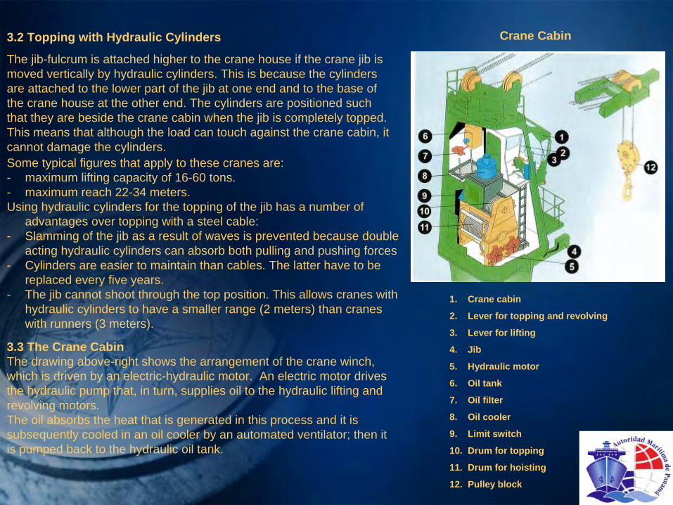
3.2 Topping with Hydraulic Cylinders
The jib-fulcrum is attached higher to the crane house if the crane jib is moved vertically by hydraulic cylinders. This is because the cylinders are attached to the lower part of the jib at one end and to the base of the crane house at the other end. The cylinders are positioned such that they are beside the crane cabin when the jib is completely topped. This means that although the load can touch against the crane cabin, it cannot damage the cylinders.Some typical figures that apply to these cranes are:-
maximum lifting capacity of 16-60 tons.-
maximum reach 22-34 meters.Using hydraulic cylinders for the topping of the jib has a number of
advantages over topping with a steel cable:-
Slamming of the jib as a result of waves is prevented because double acting hydraulic cylinders can absorb both pulling and pushing forces
-
Cylinders are easier to maintain than cables. The latter have to
be replaced every five years.
-
The jib cannot shoot through the top position. This allows cranes with hydraulic cylinders to have a smaller range (2 meters) than cranes with runners (3 meters).
3.3 The Crane CabinThe drawing above-right shows the arrangement of the crane winch, which is driven by an electric-hydraulic motor. An electric motor drives the hydraulic pump that, in turn, supplies oil to the hydraulic lifting and revolving motors.The oil absorbs the heat that is generated in this process and it is subsequently cooled in an oil cooler by an automated ventilator;
then it is pumped back to the hydraulic oil tank.
1. Crane cabin
2. Lever for topping and revolving
3. Lever for lifting
4. Jib
5. Hydraulic motor
6. Oil tank
7. Oil filter
8. Oil cooler
9. Limit switch
10. Drum for topping
11. Drum for hoisting
12. Pulley block
Crane Cabin

3.4 Bulk Crane
The bulk crane is a unit designed for loading and / or discharging using grabs and logs on standard (handy size, 30,000 tons) bulk carriers. These are usually conventional revol-ving cranes, up to 20 ton SWL.
3.5 Tanker
Manifold Crane/ Hose Crane
A tanker needs a crane to handle the loading/discharging hose. Often, the hose has to be picked up from the jetty, or out of sea in case of a buoy mooring.
The (always) hydraulic crane has a low tubular foundation, with a crane body bolted on through a slewing bearing. The jib is fitted at the top of the body. The jib is supported by a hydraulic ram. The winch is often on top of the jib, or on the crane body.
Bulk Crane:
1.Pedestal
2.Slewing bearing
3.Crane house
4.Jib
5.Grab
6.Crane
There is no crane cabin. A platform with handles, is sufficient.
However, often there is a second maneuvering stand at the ship's side. Once the hose is lifted, and bolted to the manifold pipe, and hanging in a smooth bend, the crane does not need to be operated during the whole loading or discharge operation. Depending on the ship's size, the SWL ranges from 5 tons for a 5000 tons tanker to 20 tons for a 300,000 ton tanker. The beam of the ship decides if one crane can do the job, or that two are
needed, beside each other, one on each side. The necessary reach is only 5 to 7 meters outside the ship.
Ship with bulk cranes

4. The revolving crane of the low type
In cranes of the conventional type the crane houses are 8-15 meters above the slewing bearing. However, in cranes of the low type, this distance is approximately 5 meters. The crane
cabin extends only just above
the fulcrum of the forked jib, which fuses into one box-beam jib further away from the crane. The drum of the hoisting winch, which also serves as a pulley, is placed on top of the crane house. The lifting capacity of these cranes can vary between 10 and 150 tons, the range between 12 to 35 meters.
4.1 The crane’s construction
The figures below show one of many versions of the low type cranes. A peculiarity of this crane is that
the horizontal position is merely used to “park”
the crane in the boom cradle: the boom rest.When operating, the crane should remain topped at least 15°, as indicated by the minimum and maximum range. All
revolving cranes give the load a certain freedom of rotation. The runner itself however, also has the tendency to entwine when being loaded or unloaded, For this reason, the hook is always connected to the runner via a swivel bearing, allowing the two parts to rotate independently.When a double cargo runner is used, the hook block must not rotate relative to the crane jib because this will cause the two parts of the runner to get entangled.A special electric hydraulic hook rotator can be used to prevent
this and to prevent undesired rotation of the load.When using such a device, somewhere on the crane jib there is a cable reel that slacks and hoists the power cable via a number of guide sheaves, ensuring that it never hangs too loose or too tight and that exactly follows the cargo hook. This cable reel is controlled by the crane driver with the same lever
that the driver uses to control the hoisting winch.
Revolving crane of the low type with hydraulic topping cylinders
1.Jib 8.Cam disc
2.Crane house 9.Outlet air-cooler
3.Runner 10.Floodlight
4.Topping cylinder 11.Fulcrum of the jib
5.Crane cabin 12.Crane Foundation
6.Hoisting winch 13.Hook rotator
7.Hook block

4.2 The advantages of the low type crane-The jib of a low crane is much higher compared to a conventional
crane where the top of the crane house is at the same height. This way the crane can still operate, even if there are many containers stacked on top of each other.-The low crane has a lower weight and a lower centre of gravity compared to a conventional crane with the slewing bearing at the same height. This offers more stability and increases the cargo capacity.-If containers are stacked at the same height, the low crane gives the bridge a better view.
5. Cranes for heavy cargoThe cargoes to be transported by ship are continuously increasing in weight. The shipping industry therefore builds ships for heavy cargo, where every new generation of ships gets cranes
with a higher capacity than the previous generation.The cargoes this type of specialized ships are built for, can be complete installations for the petro-chemical industry, or power stations and suchlike, as long as then are heavy components amongst the total package.Nowadays, cranes with a lifting capacity of 150 tons or more, are called ‘cranes for heavy cargo'. The lifting capacity can be as high as 800 tons.There are two basic types of heave-cargo cranes:-conventional cranes,-mast cranes.The conventional crane, has a crane house, mounted on and revolving through a slewing roller bearing, with the crane jib connected to the crane house. The slewing bearing is bolted to a
pedestal which is part of the ship’s construction and has to take the full tilting moment of the crane plus cargo. This bearing usually is a 3-row roller bearing. This type of crane has the advantage that the winches are located inside the crane house, and slewing can be carried out unobstructed.The mast crane is installed around a mast which is welded to the ship's construction. At the lower part of the mast, a platform is mounted, which can rotate around the mast. On this platform the jib, or derrick is mounted. On top of the mast is a free-turning swivel-head, with sheaves for the hanger and runner wires. The winches are installed inside the mast, or inside the pedestal of the mast, or even below deck.The hanger and runner wire go through the mast to the top-swivel. This arrangement restricts the slewing ability. Normally to + or -
270°.In connection with the cost of the slewing bearing, conventional cranes are built to a maximum of 400 tons. Higher lifting capacity is not economic, and technically too difficult. Above 400 tons the mast crane is mostly used.

1. Mast
2. Jib
3. Topping lift and running part of the hoisting rope
4. Cargo hook
5. Hook of auxiliary hoist
6. Slewing bearing
7. Mast foundation / pedestal
8. Top slewing unit
Heavy lift ship working with heavy piece of cargo Mast Crane
These cargoes have impact on the ship's construction. The double
bottom and the tanktop
have to be adapted to a large number of tons per m2. Stability requires anti-heeling tanks, with high capacity pumps to prevent listing of the ship during cargo lifting from outside the ship. Usually side tanks are used
for this purpose.To increase the stability, side pontoons can be used, attached to the ship's side, enlarging the moment of inertia of the waterline, and which can be empty or filled with water.The cranes are often used in tandem, to load a heavy part together. The load control therefore is computerized and both crane drivers have information on display about their own crane,
but also about the other crane. Reach and load are maximized via the load / moment curve calculated for each individual crane, and they are not to be exceeded.For the heavy cargoes, the ship is provided with special tools
heavy slings, shackles, spreader ,beams, etc. Also suitable lashing gear has to be provided. All these tools are load-tested, marked and certified.

5.1 Hoisting diagram
The capacity of a crane depends on the range and the maximum load of all the parts of the crane, together as well as apart. The right side of the graph shows the important impact of the range. The heeling angle is also clearly visible.
5.2 Stabilizing PontoonsStabilizing pontoons are employed when the heeling tanks fail to
reduce the list to an angle of less than 3°. The pontoons are necessary when the GM may get smaller than 1 meter. They are rigidly attached to the sides of the ship at a distance
of 0,5 meter in such a way that the ship and pontoon essentially become one.A pontoon consist of tanks that can be filled and emptied independently.The pontoon can transfer both downward and upward forces. After use, the pontoon are emptied and lifted back on board.
Stabilizing pontoon for increased waterline area
6. Gantry CranesGantry cranes are deck cranes that can travel, over the cargo, along the ship in longitudinal direction. Many different types of cranes can be attached to the
gantry. Ships without own cargo gear often use a simple gantry crane as a hatch cradle.Gantry cranes specifically for the handling of cargo can be distinguished into three main types:-
gantry cranes with a revolving crane on top-
gantry cranes with a moveable cable trolley with jib-
gantry cranes with a double portal and cable trolley without a jib.Gantry cranes are always sensitive to trim; 2º
often
is the maximum. Cranes that have a cable trolley are even more sensitive and in this case a list of 2º
is the maximum.
Multi-purpose ship with hatch cradle
If there is a revolving crane on top this maximum may be a little bit higher, but it will never be more than 5º. The four-point suspension of the hoist gives a gantry crane an excellent load control. This ensures that the load stays in line so that it can be deposited at the right location.A disadvantage of gantry cranes is their massive weight that shifts the center of gravity to a higher point. This reduces the stability and the carrying capacity. An advantage is that the ship hardly needs any strengthening; only the guide rails on deck need a strong foundation.

A characteristic of gantry cranes is the large reel on the
side for the feeder cable.The portal uses train wheels to travel over the guide rails. The
travelling part uses pinions to mesh into a toothed rack, which is attached to the longitudinal beam, which is usually the
foundation for the rails. Clamps on the sets of wheels fit around the rails without actually touching them in order to prevent the gantry from tipping over. During the voyage, heavy gantry cranes are lifted free from the rails by hydraulics jacks, in order not to damage the wheels (ball bearings) and rails by the ship's vibrations.
7. U-Gantry with a cable trolley without a fixed jib
The forces in a crane are distributed more equally in gantry cranes with two beams and
a cable
trolley without a jib than in a gantry crane with a fixed or rotating jib; there are more torsion forces in the latter. This allows the structure to be only slightly heavier than structures with only one beam. However, the crane cabin should be placed higher than in the other two types of gantry cranes because the load always remains some distance below it.Similar to the other types of gantry cranes, this type can best be
used for moving:-Containers-parcels of timber or paper-rolls thin steel-other bundled cargo.
Gantry Crane with a cable trolley and a fixed jib (front an side view) U-Gantry with trolley on a container ship

8. Side loadersSide-loader systems are used for the transshipment of small cargo units like pallets, rolls of paper and general cargo. The system comprises one or more doors in the side of the ship, and one or more elevators situated behind these doors to transport the cargo from the ramp, at quay level, to the holds and vice versa.The advantages are:-it has minimum impact on the ship's stability because it adds almost no weight.-Furthermore, the ramp lies low.-a high transfer capacity. The cargo does not have to be transported over unnecessary distances. This minimizes the waiting period.-If the route over the quay to the ship is covered, loading and discharging of delicate cargo (paper rolls) can continue during rain or snow.The disadvantages are :-The
doors in the side of the ship reduce the longitudinal strength. This has to be compensated by applying thicker plates around the hole in the ship's side.-the elevators reduce the available cargo volume.-the elevators are unsuitable for heavy loads.-there is a maximum size for the cargo to fit the dimensions of the elevators.Some characteristics of side-load systems-the maximum work load (of the elevator) is 8-20 tons-the lifting speed of the elevator is 0.33-066 m/s
(20-40 meters/min)
9. RampsRo-Ro vessels are ships where the cargo is brought on board on wheels via ramps. Loading and discharging can take place quickly, due to the speedy and mainly horizontal transport.An advantage of this is that the ship is independent from the shore facilities.In general, ramps have sufficient length to be used both in high
and low tides. Opening and closing is done with a winch or hydraulic cylinders. Closing and securing is done using hydraulic sequence locking systems, when the ramp is brought in closed position, the locking wedges, bars, hooks etc, come in, operated by hydraulic cylinders.

1. Opened side door.
2. Cargo (paper rolls)
3. Elevator
4. Quay
5. Tweendeck
Ship with three side doors Paper roll on the elevator A fork lift picks up paper rolls inside the cargo hold
Side and top view of an elevator system
Top view
Fork lift places paper rolls on the loading platform

The most important types of ramps are:-straight ramps, extending straight from the forward and aft ends
or front the side.-quarter ramps, having an angle of 45°
relative to the centerline.-slewing ramps, here the angle can be varied between +45°
and -45°
relative to the centerline.Driving from
the loading deck to the other decks also proceeds via internal ramps.These can be distinguished into:-fixed ramps-adjustable ramps-car decks that also serve as ramps.
Ro-Ro Vessel: (figure right)
1. Straight stern ramp/door
2. Hoistable ramp
3. Shell door
4. Fixed ramp with cover
5. Door
6. Car-deck access ramp
7. Hydraulic power pack
8. Hoistable car decks
9.1 Ramps between ship and shore- Straight rampsThe use of straight ramps means that the ships sometimes depend on a specially designed, sloped quay, with a landing area for the ramp. If loading and discharging is done via the fore-ship or the aft-ship, the full length of the ship has to fit in the berthing place. However, this is not necessary if the straight ramp is lowered from the side of the ship.- Straight ramp in the fore-shipA straight ramp forward, is normally combined with a watertight door, behind bow doors or sometimes a bow visor. The bow-doors have a very complicated shape as this is part of the shaped profile of the ship's bow. The inside of these doors have a flat edge with a rubber seal to make the door watertight.
The bow-doors/ visor absorb the forces of the waves, andare therefore subject to stringent requirements for its strength, locking system, seals and security. Rules stipulate that the bow ramp and the watertight door, positioned as the collision bulkhead, must be separated from each other. This is normally accomplished in one of the two following ways.
Figure 24A
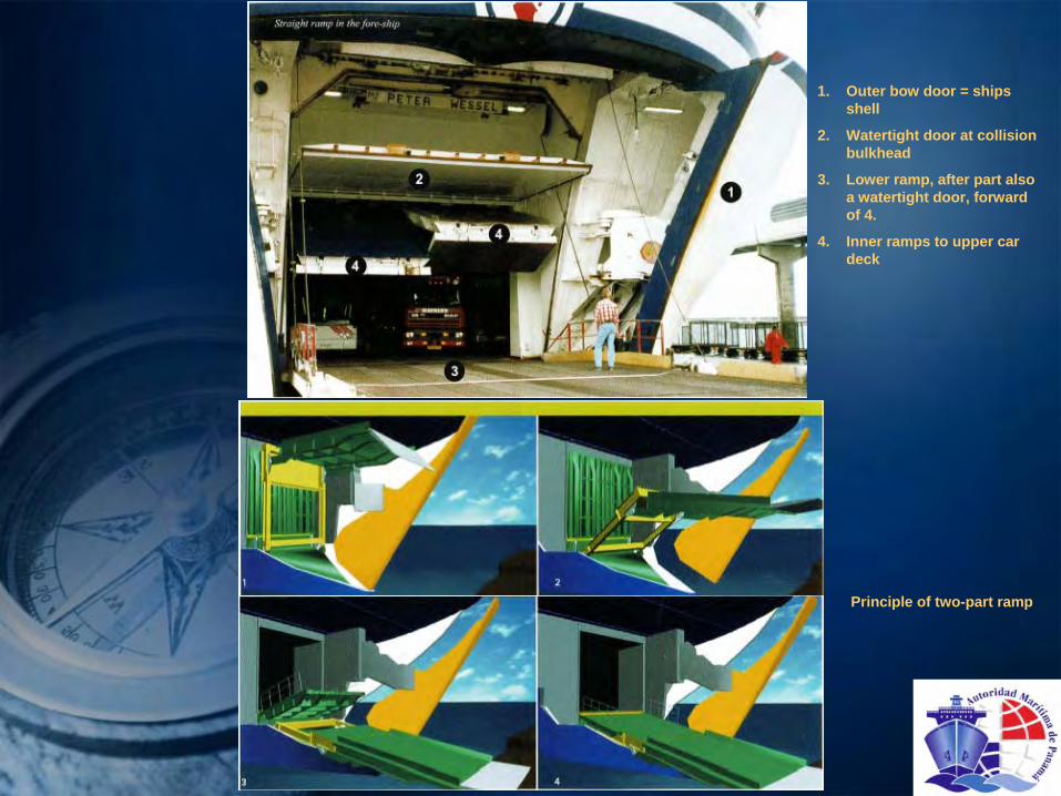
1. Outer bow door = ships shell
2. Watertight door at collision bulkhead
3. Lower ramp, after part also a watertight door, forward of 4.
4. Inner ramps to upper car deck
Principle of two-part ramp
1. With a folding frame bow ramp arrangement the collision bulkhead door can be completely separated from the rest of the ramp. This implies that no part connected to the door will extend forward of the correct position for the collision bulkhead. Door and frame is positioned forward of the collision bulkhead door and controls the folding movement through hinge connections with the outer part of the ramp. In the fully out folded position the frame, together with the outer section, forms the load carrying structure.2..A normal bow ramp/door arrangement is fitted behind the bow-doors/visor. Behind this ramp, at the position of the collision bulkhead, another set of doors is fitted.
- Straight ramp in the aft-shipThe aft-ship can suffice with just one watertight door, which, if it is flat, is used as a ramp. The closed ramp protrudes above the aft-ship.- Straight ramp in the sideStraight ramps can also be located on the side and they are comparable to the straight ramps in the stern and to the side loaders discussed earlier. The ship designer tries to make the side ramp in such a manner that, when closed, it forms a seamless whole with the ship's hull. Them are also high demands for locking, sealing
and
safety measures for these types of ramps.- Quarter rampsA quarter ramp makes an angle of approximately 45º
with the ship's centerline. This limits the orientations of the
ship in berthing to the side where ramp is located.
9.2 Inboard ramps- Fired inboard rampThe figure 24A (two slides back) shows a
ship with a fixed lamp that leads to the lower hold. Economically a disadvantage, as nothing can be stored underneath the ramp.- Hoistable car deckA hoistable
car deck is shown in the following slide. These can be used in
tweendecks, allowing two layers of cars to be transported above each other. When the tweendeck
is full, the ramp, complete with cars, is hoisted to the tweendeck
position. The space below the movable car deck can be loaded when the ramp has been hoisted.

Inboard ramp Straight ramp on the side Ship with quarter ramp in dry-dock
Straight ramp on the aft ship 1. Hoistable car deck
2. Hingeable hangers
3. Hoisting wire
4. Ramp
5. deck

- Hoistable Inboard RampsBetween decks, inside the ship, hoistable
ramps are used, which are closed, by lifting the ramp, herewith
closing the upper deck or the freeboard deck. This has implications for tightness, strength, certification. This type of ramp can be very long, depending on angle when lowered and height of the cargo space below.
10. Register and certificatesEvery ship with cargo gear has to be provided with documentation:-
Register of Ship's Cargo Gear and Lifting Appliances, accompanied with the relevant testing certificate:
♦Certificate
of Test and Examination of Winches, Derricks, and Accessory Gear.♦Certificate of Test and Examination of Cranes or Hoists and their Accessory Gear,
before being taken in use.♦Certificate of Examination and Test of Wire Ropes (for
each rope).Cranes, used in the Offshore industry, i.e. the petroleum winning, are subject to more
stringent regulations, in connection with being in use at an Offshore Unit, ship or platform, at sea, and subject to the unit's movements. These cranes are called Offshore Cranes.In case of repairs carried out to any cargo gear item, this has to he done under supervision of Class or Flag state, and generally re-testing and re-certification has to be carried out.Movable or hoistable
ramps between decks are in some cases also cargo space. A lorry
is placed on the ramp, before it is hoisted. In that case, the ramp
is cargo gear, and subject to the normal cargo gear inspections and testing. In that case the ramp needs to be registered in the cargo gear book. Wires and locking devices need to be tested by ship's staff regularly, as per ISM requirements. If this is a ramp between a lower deck and the freeboard deck, the ramp is a water-tight closing, and also subject to the regulations for load lines, with the inspections and tests applicable for
weather tightness.
- Cargo liftsTrailer lifts provide the only solution to the problem of transferring trailers between deck levels in areas of Ro-Ro
ships where longitudinal space is limited. The trailer lifts are available in a wide variety of configurations to suit individual
applications. The lay out of the installation can be arranged to enable the lift platform to act as a watertight hatch cover when secured in its upper level position.- ElevatorsPersonnel elevators need to be tested and certified by a recognized company on a yearly basis.
Slewing ramp
Quarter ramp

11. Load Testing EquipmentAll equipment intended to be used in lifting gear needs to be certified. Regulations for lifting equipment and testing are internationally harmonized. This means that material qualities are checked, workmanship is judged and that a load test has to be carried out under the supervision of a regulating body. For ships this is normally the Classification Bureau or RO.All the items in hoisting gear must be covered by a certificate,
stating an identification and a test. The load test is carried out to guarantee a Safe Working Load (SWL) or the Working Load Limit (WLL).A crane as a complete unit is tested by lifting a weight, and carrying out the normal movements like hoisting, lowering, slewing and topping. When the power to the crane is interrupted,
the brake has to hold the load. The weight for testing is heavier than the WLL. For the smallest cranes this means 25% overweight, for the biggest cranes it is 5 tons more than the SWL.Individual small items belonging to the crane, such as blocks, hooks, shackles, etc. are normally tested at a load in accordance with ILO and the Classification:-single sheave blocks at 4 times the SWL-multi sheave blocks below SWL 25 tons, at 2 x SWL-multi sheave blocks between SWL 25 and 160 tons at (0.933 x SWL)
+ 27 tons-multi sheave blocks over 160 tons, at 1.1 x SWL-hooks, shackles, chains, rings below SWL. 25 tons at 2x SWL-hooks, shackles, chains, rings above SWL 25 tons at (1.22 x SWL)
+ 20 tons.Test weights can be steel weights with a known mass; the modern variant is a water bag, which can be filled with water till the required mass is reached. A certified load cell indicates the weight. Water bags are available up to 35 tons.
Testing lifeboat davits using water bags Crane load test using a pontoon because water bags
do not exceed 35 tons
Testing the crane with water bags

Chapter 10 –
Anchor and Mooring Gear1. Overview of Anchor and Mooring Gear
1. Storage part of the mooring drum
2. Puling section of the drum (working part)
3. Brake band
4. Gear box
5. Electric hydraulic motor
6. Warping head
7. Chain in the gypsy wheel
8. Dog clutch
9. Anchor
10. Hawse pipe
11. Spurling pipe
12. Chain locker
13. Chain stopper with security device
14. Guide roller
15. Bollard
16. Guide roller
17. Deck
18. Hatch to chain locker
Longitudinal cross-section of the fore shipAnchor windlass with mooring drum and warping head
Top view

2. Anchor Equipment
2.1 PurposeThe purpose of the anchor gear (or ground tackle) is to fix the position of a ship in shallow water by using the seabed. Reasons for doing so can be:-The ship has to wait until a berth becomes available.-To load or discharge cargo when a port does not have a berth for
the ship, either temporarily or permanent.-To help with maneuvering if the ship does not have a bow thruster and/or no tugboats are available.-In emergency cases to avoid grounding.2.2 Legal demands on the anchor and mooring gearEach bow-anchor needs to be provided with a certificate, issued by Class,
based on type, materials used, weighing, and testing. The same is applicable to chain cables. A certificate for the anchor and mooring equipment is only issued after all the requirements of the Classification Society or RO are met. The original certificate has to be on board. The table below indicates equipment numbers used to determine the minimum weights and dimensions of the anchors, chains, ropes, etc. The equipment number can be found on the Midship
Section drawing.

2.3 Anchors
Anchors are the final safety resource of a ship. From the ancient times of the first boats, the men using them had a stone on some sling to keep the boat in position. Later developments show combinations with wood, ending in the stock-anchor (fisherman's anchor) with wooden stock. When propulsion or steering fails, the seafarer has to rely on his anchoring equipment. It is therefore of upmost importance that this equipment is in good
condition. A regular check of the condition of the anchor itself, the crown, anchor shackle, the chain cable, windlass, brake band and anchor securing arrangements is a master’s obligation.
In general, ships have two bow anchors and sometimes a stern anchor. There are two bow anchors for safety. Under normal circumstances one anchor is sufficient, but under severe weather
condition; or in strong current both anchors may be needed. Also, if one anchor fails, the second anchor is a back-up. A ship is not allowed to sail from any port when one anchor has been lost. In general the Classification Society may allow departure, under the condition that replacement is carried out at the earliest opportunity and that the vessel takes additional tug assistance leaving and entering port.
The stern anchor is used to prevent ships (coastal trade liners for example) from rotating due to the changes in a river current.Anchors can be distinguished as: -Conventional anchors-HHP anchors (high holding power)-SHHP anchors (super high holding power)Common conventional anchor types are: Spek, Hall, Union, Baldt. Spek
anchors have the advantage of being fully balanced.A fully balanced anchor has the following advantages:-an anchor recess that completely envelops the anchor, can be used-the shell cannot be easily damage during heaving when the anchor
flukes leave the water vertically.Accepted HHP anchors are ACI4, Pool and Danforth. CQR and Plow-type
anchors are only used on small crafts. Various copies of accepted types are made all over the world.
Pool anchor (HHP) type HG “pool N” anchor
Hall anchor (conventional anchor)
1.Crown / shackle
2.Shank
3.Flukes
4.Crown pin
5.Crown plate
6.Anchor chain with swivel

Spek anchor
Flipper anchor
Anchor d’hone
Hall anchor
AC-14 anchor
Pool TW anchor
Danforth anchor
HHP anchor with an open crown plate

The conventional type is still used a lot and serves as a standard for newer types of anchor. Conventional anchors are always cast. Newer types like Pool, can also consist of plates (or
other components) that are welded together. If the flukes are hollow, they tend to be more resistant towards bending forces. The crown plate ensures that the flukes of the anchor penetrate the sea floor. In certain types of anchors, the flukes prevent the anchor from burying itself too deep in the sea bottom.The navy uses a specially developed HHP anchor with an open crown plate (bottom plate). The advantage of this type of anchor is that it digs into the bottom more rapidly.HHP anchors are allowed to be 25% lighter in weight because their holding force is twice as strong as that of a conventional anchor. The SHHP anchors can be 50% lighter in weight, because their holding force is even larger, namely 4 times as large as with a conventional anchors, However, this type of anchor is not
accepted by Class for normal ships and can only be used on yachts and special crafts.For Offshore and Dredging special very high holding power anchors are in use, which have to be laid down in position by a tugboat, a so-called 'anchor-run boat', and also have to be lifted out by the same boat, using a separate wire attached to the crown of the anchor. These anchors are certified as Recoverable Mooring Systems. An example of such an anchor is the Flipper Delta anchor.2.4 Anchor chainThe chain runs from the chain locker, through the spurling
pipe, via the gypsy wheel of the windlass through the hawse pipe, to the anchor. The anchor chain consists of links with studs to prevent kinks in the chain (stud-link chain).The required strength and length of the chain can be determined with the aid of the equipment numbers in the previous table. This table also distinguishes two main types of material quality, namely U2 and U3. Not included in the table
are the qualities U1, which has become obsolete, and U4, which is an offshore quality.The anchor chain is composed of lengths (shackles), each with a length of 15 fathoms (15 x 1,83 = 27.5 meter). The shackles are interconnected by a kenter
shackle.In order to keep track of the outboard chain length, the paying out and heaving in of the anchor can be monitored by markings near each kenter
shackle. The markings can be white paint and/ or wire wound around the studs. The kenter
itself is red.
1. Half link 2. Locking pin 3. Stud
1.Anchor shank 2.Link 3.Swivel 4.Open link 5.Enlarged link 6.Kenter shackle 7.Crown shackle

The paid out chain length can also be monitored electronically, by sensors that carefully register how many times the gypsy wheel rotates. An advantage of
this system is that when the anchor is hove
in, the winch automatically slows down when the
anchor chain is almost completely inside and stops completely when the anchor
is home.
A D-shackle connects the anchor and the chain. A swivel is usually fixed on the chain and allows the anchor to rotate independently from the chain. The swivel can also be
connected directly to the anchor.
2.5 Hawse Pipes and Anchor PocketsThe hawse pipe is a tube that leads from the shell plating to the forecastle deck. A water-spray in the pipe cleans the chain during heaving of the anchor.During heaving, the flukes of the anchor should be parallel to the ship's shell. A collar protects the part of the ship's shell around the hawse pipe. In addition to this, the plating is extra thick in this area.Anchor pockets or recesses are sometimes made in the bow into which the anchors can be completely retracted.The advantages of the anchor recesses:-the anchors are protected from direct contact with waves-a loose anchor cannot bang against the shell (important on passenger liners)-damage to the shell by floating ice can be prevented.-prevention of fatigue damage to the anchor itself-mooring wires do not get fouled2.6 Chain Stopper / Cable StopperThe chain stopper absorbs the pull of the chain by diverting it to the hull. The chain
Water spray in hawse pipe
1.Tensioner
2.Cable stopper
3.Chain
4.Guard
stopper's holding force should be minimum 80% of tensile breaking strength of the anchor chain. Furthermore, the hawse pipe's resistance absorbs 20% and the windlass should have a holding force of 45% of the minimum break load.In most types of chain stoppers, the chain runs over a roller, sometimes equipped with a tensioner. The actual stopper mostly is a heavy bar, laid over the flat link, and secured with a strong pin. The securing consists of a hook onto which both eyes
of a steel wire are attached, This wire is put through a link of the chain and tensioned. This securing fixes the anchor in the recess thereby preventing banging of the anchor against the shell.

Cable stoppers are to be
divided into anchor securing for when the vessel is at sea, and for when the vessel is riding at anchor. When the vessel is at sea, the anchor is held by the brake band, and a securing wire or preferably a high tensile chain, through the chain cable and attached to a strong point on
the forecastle deck. The windlass should not be engaged.
When riding at anchor the chain force on big ships is held by a transverse, hingeable
bar, a strong back, incorporated in the guide roller above the hawse pipe secured on top of a flat link of the anchor chain, so that a vertical link cannot pass. The chain forces are then transferred to the ship's construction. A wire as anchor securing at sea is insufficiently strong and vulnerable to chafing especially when not lashed through a link of the chain under a stud.2.7 WinchesAnchor winches are used to heave in and pay out the anchors and anchor chains in a controlled way. The same winch can be used to operate a mooring drum. A clutch is used to connect / disconnect the gypsy wheel or the mooring drum to the main shaft. The anchor can be hove in if the gypsy wheel is coupled to the main shaft.Anchor winches normally are provided with a mooring drum, via a separate clutch. The winch turns either the gypsy, or the mooring drum, or both. The main shaft in most cases is horizontal; however, in rare cases it can be vertical, like a capstan.The winches can be powered by:-electricity; an electric motor rotates a cogwheel. The advantage of using an electric motor is that the noise is limited. Especially on passenger liners this is important.-hydraulic systems. The cogwheels are driven by a hydraulic motor, which is connected to a hydraulic pump system located below the deck. Advantages of this system are that there is no risk of (electrical) sparks and furthermore, the system is gearless.-Electric-hydraulic. The set of pumps is incorporated in the winch instead of below deck. This means that there is no need for piping systems for the hydraulic oil.-steam.
1. Main shaft
2. Gear box
3. Electric motor
4. Warping drum
5. Drum (storage part)
6. Drum (working part)
7. Gypsy wheel
8. Control level for the band break

2.8 Chain lockerThe anchor chain enters the chain locker via the spurling
pipes. Chain lockers are high and narrow, making them self-
trimming. This means that the stacked chain cannot fall over in bad weather. The end of the chain, bitter-end, is connected to an end-connection in the chain locker, with a release possibility outside the locker. On very large ships, often the connection is a weak link, to break when the chains runs out accidentally. This way the drain locker and forecastle deck will not be damaged, because a heavy chain, when running, cannot
be stopped.A grating (plate with holes) on the bottom of the chain locker makes sure that water, rust and mud can fall through, to a space below the chain locker. This has a separate manhole entrance, for cleaning purposes. A (manual) bilge pump can drain off the water. In emergencies, the chain can be
released by the bitter-end outside the chain locker.Possible types of chain release devices (bitter-end connection):-remove the pin out of the last link of the chain with a hammer. The pin is located either below deck outside the chain locker or on next to the windlass.-
a weak link in the bitter-end connection ensures that the chain breaks loose when the stress becomes too high. The breaking form must be less than the maximum holding force of the
chain.-the hand wheel can be used to release or attach the chain.
Bitter-end connection Windlass with anchor securing, guide roller and bitter-end connection
1. Working part
2. Storage part
3. Warping end

3. Mooring GearA ship's mooring system, is designed to moor a ship with a standard lay-out, on a standard jetty, with bollards at regular distances. A ship is therefore equipped with winches, with wires or ropes on drums
(no hands) and with additional ropes, which can be paid out by hand,
and tightened using the warping heads.Tankers have, through an international standard system of the oil companies, a standardized mooring system.3.1 Winches- DrumA winch drum can be made in two ways: a straight drum, and a drum in two parts, for tensioning and for storage. If the drum is made of one part, it serves both as head (storage) and as drawing and pulling drum. These types of drums are only suitable for steel wire and certain synthetics. If force is applied to a synthetic hawser, it may not slip through the layers of rope below. If this does happen, the rope gets foul. Sorting the rope out again takes a lot of time. If the drum consists of two parts, then the small part is the working drum and the other part is the storage part. The tension in a rope (with a maximum of two layers) may only be applied on the working drum.Suppose that the diameter of the drum is 30 cm, and 5 windings fit next to each other in two layers, then the pulling drum can pull
in 10 m. of rope.If the MBL (minimum break load) of the ropes is 100%, then the holding capacity of the drum is 80%, and the pulling force is approximately 1/3 of this. This rule applies to all the drums mentioned.
Ship’s fore deck:
1. Warping head
2. Drum
3. Bollards
4. Eyes to connect the stoppers
5. Guide roller (fairlead)
6. Center lead
7. Leadway
8. Head line
9. Forward spring- Warping HeadThe warping head is used:to heave in extra ropes, set them up and fasten them on the bollards.to move the ship alongside the quay over short distances. If the
warping drum is used, the gypsy wheels and the drums must not be coupled to the main shaft which would engage the anchor cable.

- Self tensioning winches
3.2 Mooring Gear Auxiliaries
One or more winches can be placed on the fore ship, depending on
the size of the ship and the preference of the owner. As shown in the picture (next slide), the warping drum, bollard and fairlead are preferably positioned in a straight line.Rollers, chocks, guide pulleys and bollards.A rope is guided from the shore via a panama chock, through the bulwark to a bollard or winch. The panama chock must
be able to withstand large forces, because the direction of the rope changes inside the panama chock. The panama chock must be curved to prevent wear of the rope.Roller fairleads can also be made of vertical and horizontal rollers. Their function is the same as the panama chock. However, the roller fairlead causes less wear to the ropes.Rollers on deck serve to change the direction of the ropes. Both the roller fairleads and the guide pulleys are able to withstand a maximum of 32 tons of pulling force depending on the
ship's size.Bollards transfer the mooring forces to the ship's hull. The outsides of the bollards have
a nose, which prevents the first few windings of the rope from slipping upwards. Above or below this, there is an eye to which the rope stopper can be attached. The stopper absorbs the forces in the rope temporarily
so that the rope can be taken off the warping drum and
Control for the self tensioning winch:
1.Control lever for the winch
2.Cooling fan
3.Control for the self-tension setting
CapstanThe capstan consists of a warping drum with a vertical drive shaft that is driven either electrically, hydraulically or electro-hydraulically. The capstan is usually placed on the aft ship and, if the ship is very long, on the sides. If the capstan is combined with a gypsy wheel, it can be used to control the (stern) anchor i.e. a vertical anchor windlass.
- Capstan
Self tensioning winches can be adjusted to maintain a certain holding force. If this value is exceeded, then the winch automatically adjusts the
length of wire to the new force (too much bolding force: slacking; too little holding force: heaving). This system is frequently used by ships that load and discharge quickly (container ships and Ro-Ro vessels) or if there is a large tidal range in the port.
placed on the bollard. The double bollard is provided with two ridges to prevent the rope from moving. A stopper lug has been fitted as rope stopper.For the non-moving parts like panama chocks, the allowed force is 1/5 of the
maximum static force that this part is able to sustain.

Panama chock Panama chock & roller fairlead
Bollard:
1.Guide roller 2.Nose 3.Stopper eye
3.3 Emergency towing system for tankers
This has the advantage that the strands in the core can be arranged in a parallel fashion: this gives the maximum tensile strength. The mantle itself rarely contributes to the tensile strength. The threads in the core need not be resistant to wear as the mantle provides the wear resistance. Therefore it is important that the wear resistance of the mantle is higher than the wear resistance of the core. A mantle keeps the cable round and compact, which reduces sensitivity to wear.
4. Rigging4.1 Cables & ropesGeneralCables are used on ships:to moor the ship and maintain its position at a jetty, and for towing.for the cargo gearin fishing and dredgingThe cables mentioned in “a.”
are usually made of rope and called hawsers or lines. The cables used in “b.”
and “c.”
generally are steel cables. The latter are described in more detail in the section "description of common cables".
Rope can be made from either natural or synthetic fibers. Nowadays, with a few exceptions, most ropes are made from synthetic fibers. The synthetic fibers are manufactured from mineral oil products that have undergone a chemical process.
The rotation of the threads is opposite to the strands, preventing the rope to unlay. Below some (of the many) types of ropes are categorized according to the way they have been stranded (plaited).
Some rope types have a mantle. The purpose of the mantle is to keep the strands in the core together.
In recent years a number of environmental disasters involving tankers has shown how difficult it is to make a connection with a ship in distress. The IMO demands that tankers with a carrying capacity of more than 20,000 tons have an emergency towing connection forward and aft. Forward this is a stopper, which holds a standard chain, when pulled through from outside to inside (the same stopper as the tanker uses when mooring on a single buoy). Aft it has to be a prepared system. This means a rope or wire in the water, with a messenger buoy, ready to be picked up and fastened by a tugboat, and that can be deployed by one man.
1.Bow lines 2.Spring lines

Some core types that can be present in core with a mantle cables:-Braided-Stranded-parallel strands-parallel threadsThe characteristics that are important when using or buying rope:-MBF (Minimum Break Force). This is the minimum force in KN needed to break the rope.-Elasticity.-Density. The larger the density, the heavier the rope. It is important to know whether the density is smaller or larger than 1,000 t/m3, in other words: does the rope sink or float.-UV resistance. After several years, sunlight can degrade a rope.-Wear resistance.-Construction .The number of strands and the way that the rope is
plaited, the presence of a mantle.-Water absorption, expressed as a weight percentage of the rope.-Backlash or snapback. This indicates if, in case of breaking, the rope falls "dead" on the deck, or snaps back. Rubber has a large backlash.-Creep limit. This is the lengthening of the cable in time under constant tension.-Chemical durability. This indicates how well the rope can resist
(the action of) chemicals.-A knot or splice in a cable can reduce the strength by as much as 50%.-TCLL value (thousand cycle load level). This is the cyclic load level as a percentage and as an absolute value of the maximum load under wet conditions. This is the load at which a cable will break when it has undergone the load a 1000 times. For example, if the TCLL value of a 100 ton/f Cable is 50%, or 50 ton/f, then the cable will break if subjected to a 50 ton/f load a 1000 times.
3 strand Parallel fiber core with mantle
4x2 strand braided Braided
1. Fiber
2. Thread
3. Rope yarn
4. Strand
5. 3-Strand rope

4.2 Description of common cables
a.
High grade cables
b.
Polyamide
c.
Polyester
d.
Polyolefines
e.
Natural rope
f.
Steel cables
a. High grade cablesAramide
and High Module Poly-Ethylene (HMPE) are high grade cables. Kevlar, Twaron
and Technora
are aramide
brand names and Dyneema
and Spectra are HMPE brands. The difference between the two types is that aramide
has a lower (thus better) creep, but aramide
sinks whereas HMPE floats. High grade cables are relatively new
products and strength wise they are comparable to steel cable of the same diameter. However, the price
is 5 -10 times higher than steel cables.Advantages over steel cables are:-light weight-easy to handle-non-conductive-small backlashb. PolyamidePolyamide is better known as nylon. Polyamide ropes sink (density > 1,000 kg/m³) and absorb water after being a few days in contact with water. The absorption of water adds 4% to the rope's weight. This can reduce the MBF by 20%. Polyamides have a large elasticity. A consequence of this is the
backlash when parting. The rope sweeps over the deck and endangers the people present there. Certain types of polyamides can be spliced and re-used after the rope has snapped. However, especially cheap ropes are disposed of when they snap, and a new rope is ordered.c. PolyesterPolyesters are very resistant to wear and very durable, both in wet and dry conditions. In mechanical characteristicspolyester resembles nylon, except that it is more resistant to wear. Furthermore, polyester is more expensive. The density of nylon (1.14) is lower than of polyester (1.38) and the energy absorbing capacity of nylon is higher, making it more suitable to absorb large force variations. For this reason, nylon is often
used as a stretcher, to protect steel cables from large shock loads.
Towing wire with a stretcher Lines & cables resting on a bollard

d. PolyolefinesThere are two types of polyolefine
rope, namely "High Performance Ropes" and "Standard Ropes". The
difference between these two lies not just in the MBF, but also in the qualities like UV sensitivity and wear resistance, which increase the durability of the rope. High performance ropes can also be found with a mantle.Polypropylene, polyethylene and mixtures of these compounds are polyolefines. Many high performance ropes like the Tipo-eight are also polyolefines. Polyprop
is a polyolefine
rope that is often used.Its advantages are:-it floats-it is relatively cheapThe disadvantages are:-not very resistant to wear-low TCLL value-short lifespane. Natural ropeNatural fiber rope has been replaced on most ships by synthetic ropes. In general, the only type of natural rope still in use on ships is manilla
rope. Manilla
rope is manufactured from the abaca fiber that is present in the
leaf stalks of the manilla
plant.Although the resistance to chemicals and UV light is good, the MBF is about 2-8 times smaller than the MBF of synthetic ropes.Manilla
on ships is used for the pilot ladder, boat ropes of lifeboats and helicopter nets.The reason for this is:-manilla
is less sensitive to fire and burns slower.-Manilla
is rough and hairy, ,therefore it does not slip easily, especially when wet.f. Steel wire ropesSteel cables or wire ropes have advantages and disadvantages. They are strong, cheap, have little elongation under tension, have a high wear resistance, but they are heavy, and they rust.They are used where the circumstances allow or demand it for instance for hoisting and luffing
wires in cranes, mooring wires for tankers and bulk carriers, anchor wires in dredging and offshore, towing wires for fishing and tugboats. In case of fire they are not immediately destroyed.Steel wires are available in numerous constructions, depending on the requirements.There are basically two steel tensile strength grades: 1770 N/mm²
and 1960 N/mm². Cables are made of a number of strands, turned in a long spiral around a core. The strands consist of a number of usually galvanized wires.
An eye is spliced into a rope

For flexible wire, the core is rope, and when flexibility is not
necessary, the core is steel. A steel core makes a stronger wire. Rope core when oiled, lubricates the wire, but allows deformation under stress and bending. Steel wires need maintenance. Regularly greasing is essential.The strength is optimal when different sizes of wires are used in one strand, so that the space between the wires is optimally filled. This is done in cables made according to the Warrington-Seale (WS), the section is then optimally filled with steel and the permeability for water is less.Like ordinary rope, there are right hand and left hand laid cables. Analogue to synthetic rope, the direction of rotation of strands and wires is mostly opposite, called "ordinary lay”.Other constructions are Cross-lay, Lang's Lay, Non-Rotating, etc. When wires and strands have the same direction of
rotation, there is the possibility of turning open. These types of wires are only to be used where the ends, both sides, are fixed, like as mast-stays, and bridge suspensions. Non-Rotating cables are always cross-lay.During the fabrication process the wires in the strands can be preformed into the helical form which they get in the finished state, to reduce internal stresses in the rope. That prevents unspinning, and a broken wire does not stick out. The construction of steel wire is given in a formula.For example: Galvanized, Diam. 36 mm, 6 x 36 ws
+ iwrc.It means 36 mm diameter, 6 strands with each 36 galvanized wires, warrington
seal (ws), and an independent wire rope core (irwc). Warrington seal is a means of constructing a wire rope from wires with different diameter, so that water ingress is limited.Steel wire is mostly galvanized, but untreated steel wires also exists, and for special purposes stainless steel is used.
4.3 Various partsVarious rigging parts are explained on these slides:-End connections-Shackles-Turnbuckles or bottle screws-Thimbles-Sockets— End connectionsEnd connections are needed to connect a wire to something else. Often shackles are used for the connection.— Safety hookA safety kook is shown in the next slide. It prevents the load from falling out of the hook, even if the load is resting. The hook can only be opened by pressing the safety pin.
Lifeboat hoisted with 19x7 steel wires

End links
1.Gaff socket with rolled connection 2.Cast spelter socket 3.Rolled eye terminal 4.Thimbled talurit eye 5.Spliced eye with thimble 6.Thimbled flemish eye, swaged 7.Wedge socket
1.Brand or type marking 2.Chain size (chain 7/8 of an inch) 3.Class, grade 8 (high grade steel) 4.Safety pin 5.Spring
— ThimblesA thimble is a ring inside a spliced eye, to enlarge the radius of the wire in a splice, where this comes around e.g. the pin of a Shackle, and thus protecting the wire and is usually made of galvanized steel. Its function is to protect the eye of a cable from wear and damage.
Thimble
— Shackles Shackles can be divided into Bow shackles and D shackles. The light types can be closed with a screwed bolt, the heavy types with a bolt and a nut. These can both come with or without a locking pin. Their general purpose is to connect certain parte to each other or to the ship. The Safe Working Load (SWL) can vary from 0.5 ton up to 1000 tons and more.
1.Bow shackle with safety pin 2.Bow shackle with screwed bolt 3.D-shackle with safety bolt and nut 4.D-shackle with screwed bolt
— TurnbucklesTurnbuckles are used to connect and tension steel wires or lashing bars. The bottle screw consists of two screws, one with a left screw thread, and the other with a right screw thread. These are connected by a house.
Safety Hook
Turnbuckle
1.Gaff
2.House
3.Thread, one left, one right handed
4.Eye
Shackles & wires
Spreaders for heavy or large loads

— Steel wire clampsA steel wire clamp can be used to quickly make an eye in a cable. The U-bolt of the clamps should be attached to the part of the cable that is free from pulling forces. The bolts should be attached to the "dead" part where no pulling forces are acting on the cable.Steel wire clamps may not be used for lifting purposes, with an exception for guys and keg sockets to make sure that the cable does not slip.— SlingsWhen lifting objects, often slings are needed. A sling is a wire
with at each end an eye spliced or clamped. The eye can be long or short, all depending on the purpose. When the item to be lifted has lugs welded on it, a sling with talurits
and shackles can be used. In
Wire clamps on a cable
Wire clamp on a kegsocket
Cable-laid sling
other cases long eyes are more versatile. These eyes can be talurit
clamped, but better is a flemish
eye, with a swaged clamp. A flemish
eye is a very simple, but very strong splice. From a wire with an even number of strands, the strands are turned loose over the double length of the eye. Over that length the wire is split in two sets of strands. Half the number of strands are laid in a bend in one direction, the other half into the other direction, meeting together in opposite direction, forming an eye. The strands are turned into each other, forming a wire. Where the ends come together a conical steel bush is placed on forehand, which is pressed together, preventing the wire ends from jumping loose.The strongest sling is the grommet. A wire is turned around a circular rod, say six times the circumference, forming a cable, after which the rod is putted out, and the wires, acting as strands, remain, turned around themselves. The ends are put away
inside the rope. A grommet is very flexible and very strong. The heaviest grommets, for offshore lifts, reach a calculated MBL of 7500 tons. Testing is not possible, but the MBL of the individual wires is a known figure, found from a breaking test of a sample. Cable-laid slings are very heavy cables, constructed from steel cables with varying diameters, to fill the available diameter as solid as possible. Eyes are spliced at each end. The built-up rope diameter can go as high as 350 mm. The calculated MBL can go as high as 4000 tons.— Fabric SlingsModern slings are fabric. Woven front modem fibers very light and strong band-type slings are made, with one disadvantage: they can easily be damaged by sharp items. But strength-weight ratios can be extremely high, when modern fibers as Dyneema, Aramide, or other carbons are used. Very flexible and soft slings are made from Dyneema
in long straight threads, not laid, inside a canvas tubing. This type of sling is very friendly to machined or polished steel objects.

4.4 Forces and stresses- Some definitionsSafe Working Load (SWL) or Working Load Limit (WLL) is the maximum acceptable load on an item (shackle, hook, wire, derrick, crane, etc.).Minimum Breaking Load (MBL) is the guaranteed minimum load at which an item, when tested to destruction as a sample for a large number of identical items, will fail. So, on average, most items will fail at a higher load. The load-stretch diagram below shows that the tested chain actually failed at a higher load than the MBL. The diagram also shows that proof loading by the manufacturer is done to 2.5 times the safe working load. For a re-certification test, the proof load will be 2 times the SWL.Figures normally used for the ratio WLL/MBL (or SWL/MBL) are: -For chains:
1: 4-For steel wires and shackles: 1: 5-For ropes:
1: 6 or 1: 7- Forces in wiresThe figure on the right shows the forces in a wire when a weight
of 1000 N is lifted, and how the force in a rope or wire increases as a function of the angle
between the components. When that angle exceeds 90°
the increase is excessive. Between 120°
and 150°
the forces run up to 1950 N. The angle is therefore not allowed to exceed 120°. The material used for the wire does not influence the forces.
Load/stretch diagram of a grade 8 chain
Spreader with hook, SWL 6000 tons
Blocks with rams horns of heavy cargo gear, SWL 400 tons

THANK YOU!