lab c2 silabs 2: input; byte operations...
TRANSCRIPT
Chapter 20LC
Lab C2 SiLabs 2: Input; ByteOperations
Contents
20LCLab C2 SiLabs 2: Input; Byte Operations 120LC.1Port Pin Use in This Lab . . . . . . . . . . . . . . . . . . . . . . . . . . . . . . . . . . . . . . . . . . . . . . . . . . . . 220LC.2Bitflip LED Blink Program, Recast with Subroutine . . . . . . . . . . . . . . . . . . . . . . . . . . . . . . . . . . . . . . 2
20LC.2.1Some Oddities of PUSH AND POP . . . . . . . . . . . . . . . . . . . . . . . . . . . . . . . . . . . . . . . . . . 320LC.3Bit Input: “Blink LED if. . . ” . . . . . . . . . . . . . . . . . . . . . . . . . . . . . . . . . . . . . . . . . . . . . . . . . . 4
20LC.3.1Bit Input . . . . . . . . . . . . . . . . . . . . . . . . . . . . . . . . . . . . . . . . . . . . . . . . . . . . . . . . 420LC.3.2C language Equivalent: “If. . . ” . . . . . . . . . . . . . . . . . . . . . . . . . . . . . . . . . . . . . . . . . . . . . 7
20LC.4Byte Operations, In and Out . . . . . . . . . . . . . . . . . . . . . . . . . . . . . . . . . . . . . . . . . . . . . . . . . . 720LC.4.1Hardware for Byte In, Byte Out . . . . . . . . . . . . . . . . . . . . . . . . . . . . . . . . . . . . . . . . . . . . 720LC.4.2Code for Byte In, Byte Out . . . . . . . . . . . . . . . . . . . . . . . . . . . . . . . . . . . . . . . . . . . . . . . 8
20LC.5Add Keypad Value to Running Sum . . . . . . . . . . . . . . . . . . . . . . . . . . . . . . . . . . . . . . . . . . . . . . 920LC.5.1Code for 8-bit Running Sum . . . . . . . . . . . . . . . . . . . . . . . . . . . . . . . . . . . . . . . . . . . . . . 920LC.5.216-bit Running Sum . . . . . . . . . . . . . . . . . . . . . . . . . . . . . . . . . . . . . . . . . . . . . . . . . . 11
20LC.6. . .You Can Disconnect Cables, etc. . . . . . . . . . . . . . . . . . . . . . . . . . . . . . . . . . . . . . . . . . . . . . . 14
REV 01; March 23, 2015.
1Revisions: check init caps in headings, space after §(3/15); add headerfile and index (7/14); interchangeHi, Lo port ass’mts in 16-bitdisplay, to be consistent with u4 port use; update display photos to show no-label display of 8 and 16-bit quantities (4/14); replace keypadhardware image to fit new display (3/14); add reference to 16-bit data display LCD (4/13); add note suggesting disconnect displays andkeypad (11/11); correct pushbutton ref in text to P0.4 (3/11).
1
2 Lab C2 SiLabs 2: Input; Byte Operations
20LC.1 Port Pin Use in This Lab
Today, we make use of just one more PORT0 pin, in addition to the LED drive of lab C1: an input pin drivenby a pushbutton.
Later in this lab, in § 20LC.4 on page 7, we also add byte input and output devices at two other ports, PORT1(display) and PORT2 (keypad), and finally we also ask PORT0 to drive another 8-bit LCD display. That lastaddition does not conflict with the two PORT0 uses shown in fig. 1.
Figure 1: PORT0 pin use in today’s lab: a pushbutton input added
20LC.2 Bitflip LED Blink Program, Recast with Subroutine
Last time, we slowed the LED-blinking program by putting time-wasting DELAY code inline with the bitflipcode. This works, but makes the code relatively hard to read, and clumsy to write. In a tiny program likeBitflip this hardly matters. But in a more complex program it is useful to break the code into modules, calledsubroutines, all of which are stitched together by a main calling program. Here, we will make that formalchange to the delayed bitflip program of Lab C1. The behavior of the LED will be the same. The code willbe easier read.
The code below is just the old code, rearranged—with a few details added that permit the main program toinvoke the two subsidiary subroutines: one subroutine takes care of the SiLabs special initializations (we callthis patch of code “USUAL SETUP,” and it reappears in almost all of the programs in this series of labs).The other subroutine, DELAY, simply uses up about one second, to set the LED blink rate, as in Lab SiLabsµ 1.
We have made one small change in “USUAL SETUP,” relative to that used in the delay code of µ 1: we haveslowed the system clock by a factor 8, as the ’410 permits, in order to save a little power. In this application,certainly this slowdown has no appreciable effect. It is not necessary, but we thought we’d show this option—which is the IDE’s default, but here imposed by the explicit command, ORL OSCICN, #04h ; sysclk = 24.5 Mhz /8.
We’ll list the program, and then look at some of its details.
; bitflip_delay_subroutine.a51 bitflip program, with delay for full-speed operation
$NOSYMBOLS ; keeps listing short$INCLUDE (C:\MICRO\8051\RAISON\INC\c8051f410.inc)
ORG 0 ; tells assembler the address at which to place this code
ACALL USUAL_SETUPSETB P0.0 ; start with LED OFF (it’s active low)
FLIPIT: CPL P0.0 ; toggle LEDACALL DELAY ; waste some timeSJMP FLIPIT ; do it forever
;--- SUBROUTINES ----DELAY: PUSH ACC ; save the registers that this routine will mess up
PUSH BPUSH 4 ; this saves register R4--in the zeroth set of registers
Lab C2 SiLabs 2: Input; Byte Operations 3
MOV A,#0 ; maximize two delay values (0 is max because dec before test)MOV B,#0 ; ...and second loop delay valueMOV R4, #10h ; 1 second delay: this multiplies the 64K other loops
INNERLOOP: DJNZ B, INNERLOOP ; count down innermost loop, till inner hits zeroDJNZ ACC,INNERLOOP ; ...then dec second loop, and start inner again.DJNZ R4, INNERLOOP ; now, with second at zero, decrement the outermost loop
POP 4POP BPOP ACCRET ; back to main program
USUAL_SETUP: ANL PCA0MD, #NOT(040h) ; Disable the WDT.; Clear Watchdog Enable bit
; Configure the OscillatorORL OSCICN, #04h ; sysclk = 24.5 Mhz / 8
; Enable the Port I/O CrossbarMOV XBR1, #40h ; Enable CrossbarRET
END
The subroutine is invoked by a CALL operation, here in the shorter ACALL version. (Subroutines and thestack are discussed in Classnotes µ2). Subroutine etiquette requires that the subroutine save any values it willmess up, so that the main program can operate properly on a return from the subroutine. The saving hereis done with PUSH operations; the same registers are restored, before exit from the subroutine, with POPoperations. RET pulls the “return” address off the stack, so that execution can resume at the main program’sinstruction that follows the ACALL.
20LC.2.1 Some Oddities of PUSH AND POP
20LC.2.1.1 Potential Ambiguity in the Name “Rn”
One of the PUSHes is odd: PUSH 4 ; this saves register R4--in the zeroth set of registers. Why“PUSH 4” rather than “PUSH R4”? Because “R4,” surprisingly, is ambiguous: the 8051 has four sets ofscratch registers, named R0. . .R7. The 8051 resolves the ambiguity by referring to two bits in its PSW (“Pro-gram Status Word”) register. After a reset, these two bits are at zero, so the controller uses the zeroth registerset, by default.
But the broad-minded assembler program does not dare to presume which of the four register sets is intended.So, it requires that we describe the zeroth R4 by its on-chip address. “4” is the (unambiguous) address of thezeroth version of R4.2
20LC.2.1.2 “A” Wants to be Called “ACC”
As we noted in Classnotes µ2, PUSH and POP require that we call register A “ACC.” Don’t ask why!3
2We wish the assembler were bold enough to assume that the particular R4 intended is the one in use at the time of the reference. Butthis is not the way 8051 assemblers work. [ASK PAUL IF THERE’S AN OBJECTION TO THIS PROPOSAL]
3. . . because we don’t know.
4 Lab C2 SiLabs 2: Input; Byte Operations
20LC.2.1.3 The Result, We Hope: Code That’s Easier to Follow
The use of subroutines makes even this simple program easier for a reader to make sense of. The guts of theprogram sit near the start:
FLIPIT: CPL P0.0 ; toggle LEDACALL DELAY ; waste some timeSJMP FLIPIT ; do it forever
Appearing early, and all in one place, this code is easier to make sense of than the code of the delayed-bitflipprogram of Lab SiLabs 1, where the delay and initialization code was placed inline.
From this point, we will use subroutines regularly, in an effort to make our programs readable and also topermit building them up in stages. This effort recalls our methods in the analog part of this course: there, wetried to design and test subcircuits that we then could link as modules. The method eased our work in bothdesign and analysis—and the motive for use of subroutines is the same.
20LC.3 Bit Input: “Blink LED if. . . ”
In the first micro lab, we made an LED blink. As an application for an intelligent controller, that’s not veryimpressive. A ’555 oscillator can make an LED blink. Now we will modify the program just slightly, so thatthe LED blinks unless we press a pushbutton. That’s still not very impressive, you may protest: a pushbuttonon the ’555 RESET* line could achieve the same result.
Well, OK: fair enough. But we’d like to make a claim that the ability of the processor to do one thing underone condition, another thing under another condition amounts to a glimmering of intelligence. This ability isfundamental to what can make a computer seem smart. So, let’s add this capability to the blinker program.
20LC.3.1 Bit Input
20LC.3.1.1 Hardware
When using buses—as you have seen in today’s class notes—responding to a bit input requires some hardware(a 3-state to get the information onto the data bus) and then a bit-testing operation on the accumulator register(also called “ACC” or just “A”).
Using a controller’s built-in port, as in the ’410 (which provides no buses), data inputs are much simpler.An input signal (either a bit as in bitflip if.a51, or a byte, as in § 20LC.4 on page 7) is tied directly to thecontroller’s port pin or pins: no need for a 3-state, because the pin accesses not a public bus but a private roadinto the controller.
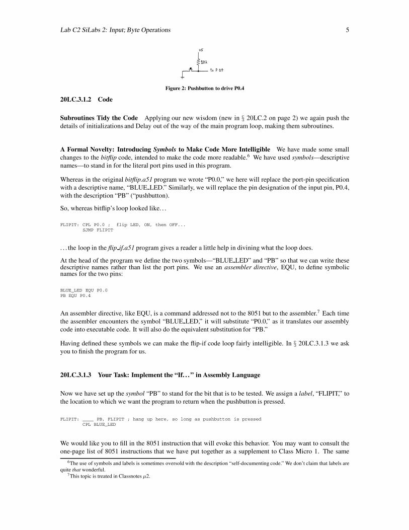
The hardware to let us talk to the ’410 with a pushbutton thus is extremely simple: a pushbutton can groundthe input signal while a pullup resistor otherwise pulls it to +5V.4 If switch bounce matters, then at least acapacitor must be added, to slow the edge.5 But let us omit that here, for maximum simplicity, since bouncedoes not matter in this program. Wire this on a breadboard strip.
4On some 8051/’410 ports even the pullup can be omitted. But at PORT 0, which we use here, no such pullup is present.5As you know, a true debouncer for an SPST switch requires more than an RC circuit. It also requires a Schmitt trigger to square
up the transition of the slow RC. But a processor input, unlike a true edge-triggered input such as a flip-flop clock, does not need thatsquaring up, as we will see next time, in Lab C3.
Lab C2 SiLabs 2: Input; Byte Operations 5
Figure 2: Pushbutton to drive P0.4
20LC.3.1.2 Code
Subroutines Tidy the Code Applying our new wisdom (new in § 20LC.2 on page 2) we again push thedetails of initializations and Delay out of the way of the main program loop, making them subroutines.
A Formal Novelty: Introducing Symbols to Make Code More Intelligible We have made some smallchanges to the bitflip code, intended to make the code more readable.6 We have used symbols—descriptivenames—to stand in for the literal port pins used in this program.
Whereas in the original bitflip.a51 program we wrote “P0.0,” we here will replace the port-pin specificationwith a descriptive name, “BLUE LED.” Similarly, we will replace the pin designation of the input pin, P0.4,with the description “PB” (“pushbutton).
So, whereas bitflip’s loop looked like. . .
FLIPIT: CPL P0.0 ; flip LED, ON, then OFF...SJMP FLIPIT
. . . the loop in the flip if.a51 program gives a reader a little help in divining what the loop does.
At the head of the program we define the two symbols—“BLUE LED” and “PB” so that we can write thesedescriptive names rather than list the port pins. We use an assembler directive, EQU, to define symbolicnames for the two pins:
BLUE_LED EQU P0.0PB EQU P0.4
An assembler directive, like EQU, is a command addressed not to the 8051 but to the assembler.7 Each timethe assembler encounters the symbol “BLUE LED,” it will substitute “P0.0,” as it translates our assemblycode into executable code. It will also do the equivalent substitution for “PB.”
Having defined these symbols we can make the flip-if code loop fairly intelligible. In § 20LC.3.1.3 we askyou to finish the program for us.
20LC.3.1.3 Your Task: Implement the “If. . . ” in Assembly Language
Now we have set up the symbol “PB” to stand for the bit that is to be tested. We assign a label, “FLIPIT,” tothe location to which we want the program to return when the pushbutton is pressed.
FLIPIT: ____ PB, FLIPIT ; hang up here, so long as pushbutton is pressedCPL BLUE_LED
We would like you to fill in the 8051 instruction that will evoke this behavior. You may want to consult theone-page list of 8051 instructions that we have put together as a supplement to Class Micro 1. The same
6The use of symbols and labels is sometimes oversold with the description “self-documenting code.” We don’t claim that labels arequite that wonderful.
7This topic is treated in Classnotes µ2.
6 Lab C2 SiLabs 2: Input; Byte Operations
information, in wordier form, appears at pp. 15-16 of the Philips/NXP programmer’s guide for the 8051:http://www.nxp.com/acrobat download2/various/80C51 FAM PROG GUIDE 1.pdf (dec. 2010).
When you have filled in the code, the label and symbol offer strong clues to the logic of this loop. Perhapsyou find FLIPIT: ____ PB, FLIPIT and CPL BLUE_LED cryptic still. But the symbols help, do they not?
Program Flow Conditioned by Pushbutton The novelty in the behavior of bitflip if.a51— distinct fromthe novelty in the program’s listing—isthe code’s testing of an input. The conditional jump command that weasked you to fill in implements the “if” in the “Blink. . . if. . . .” This conditional (“if”. . . ) keeps the programstuck on this line so long as the pushbutton holds P0.1 at a logic Low. Only when the pushbutton is released,permitting P0.1 to go High, does the program flow reach the next line, where the LED-flipping occurs
Here is the full program listing:
; bitflip_if.a51 toggle LED, slowly--if pushbutton NOT pressed
$NOSYMBOLS ; keeps listing short$INCLUDE (C:\MICRO\8051\RAISON\INC\c8051f410.inc)
BLUE_LED EQU P0.0PB EQU P0.4 ; pushbutton will determine whether LED is to toggle or not
ORG 0 ; tells assembler the address at which to place this code
SJMP STARTUP ; here code begins--with just a jump to start of; real program. ALL our programs will start thusORG 80h ; ...and here the program starts
STARTUP: ACALL USUAL_SETUPCLR BLUE_LED ; start low, just to make it predictable
FLIPIT: ___ PB, FLIPIT ; hang up here, so long as pushbutton is pressedCPL BLUE_LED ; ...but flip the LED when button not pushedACALL DELAYSJMP FLIPIT
;----SUBROUTINES ------USUAL_SETUP: ; Disable the WDT.
ANL PCA0MD, #NOT(040h) ; Clear Watchdog Enable bit
; Configure the OscillatorORL OSCICN, #04h ; sysclk = 24.5 Mhz / 8, for lower power
; Enable the Port I/O CrossbarMOV XBR1, #40h ; Enable Crossbar
RET
DELAY: PUSH ACC ; save the registers that this routine will mess upPUSH BPUSH 4 ; this saves register R4--in the zeroth set of registers
MOV A,#0 ; maximize two delay values (0 is max because dec before test)MOV B,#0 ; ...and second loop delay valueMOV R4, #10h ; 1 second delay: this multiplies the 64K other loops
INNERLOOP: DJNZ B, INNERLOOP ; count down innermost loop, till inner hits zeroDJNZ ACC,INNERLOOP ; ...then dec second loop, and start inner again.DJNZ R4, INNERLOOP ; now, with second at zero, decrement the outermost loop
POP 4POP BPOP ACCRET ; back to main program
END
We found the blink rate a little low for our tastes. Try speeding it up by, say, a factor of four.
Lab C2 SiLabs 2: Input; Byte Operations 7
20LC.3.2 C language Equivalent: “If. . . ”
C language code that would achieve the same result—flipping an LED unless a pushbutton grounds an inputnamed “inbit”—looks a lot like the assembly language loop of § 20LC.3.1.2 on page 5. In C the “if” isexplicit; in assembly language the “if” is expressed in the conditional jump operation that you filled in, in§ 20LC.3.1.3 on page 5.
if(!inbit) outbit = outbit;else outbit = !outbit;
For code as simple as this, C offers no advantage over assembly.
20LC.4 Byte Operations, In and Out
We have used bit operations, so far, because they give such a quick reward for minimal wiring. Byteoperations—with which we started on the Big Board branch of the micro labs—are just as simple to code,but require a very little more wiring effort. Let’s make that small effort, now, and do some byte operations.
20LC.4.1 Hardware for Byte In, Byte Out
20LC.4.1.1 Byte Input, from Keypad
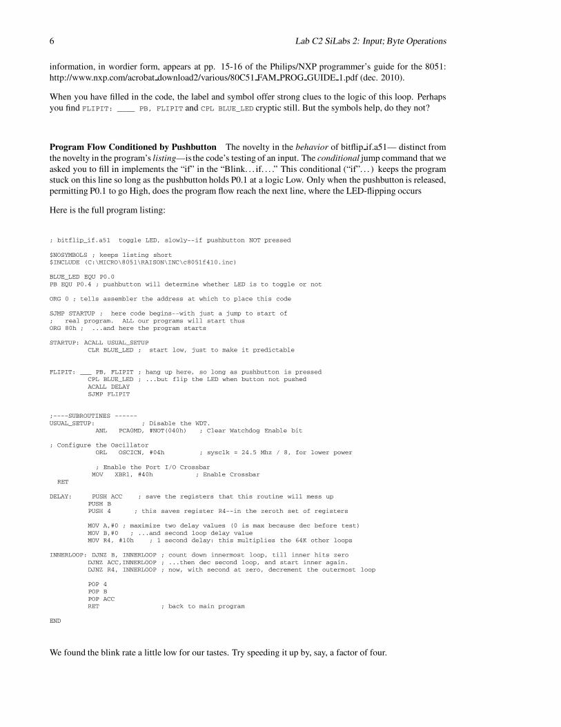
As input device, let’s use the keypad, with its 16-pin DIP connector. On a breadboard strip you can convertthe DIP’s 8 data lines—which unfortunately lie on two sides of the connector—into the 8-in-a-row form thatwill be convenient for wiring to the ’410:
Figure 3: DIP connector from keypad, adapted to in-line flat cable
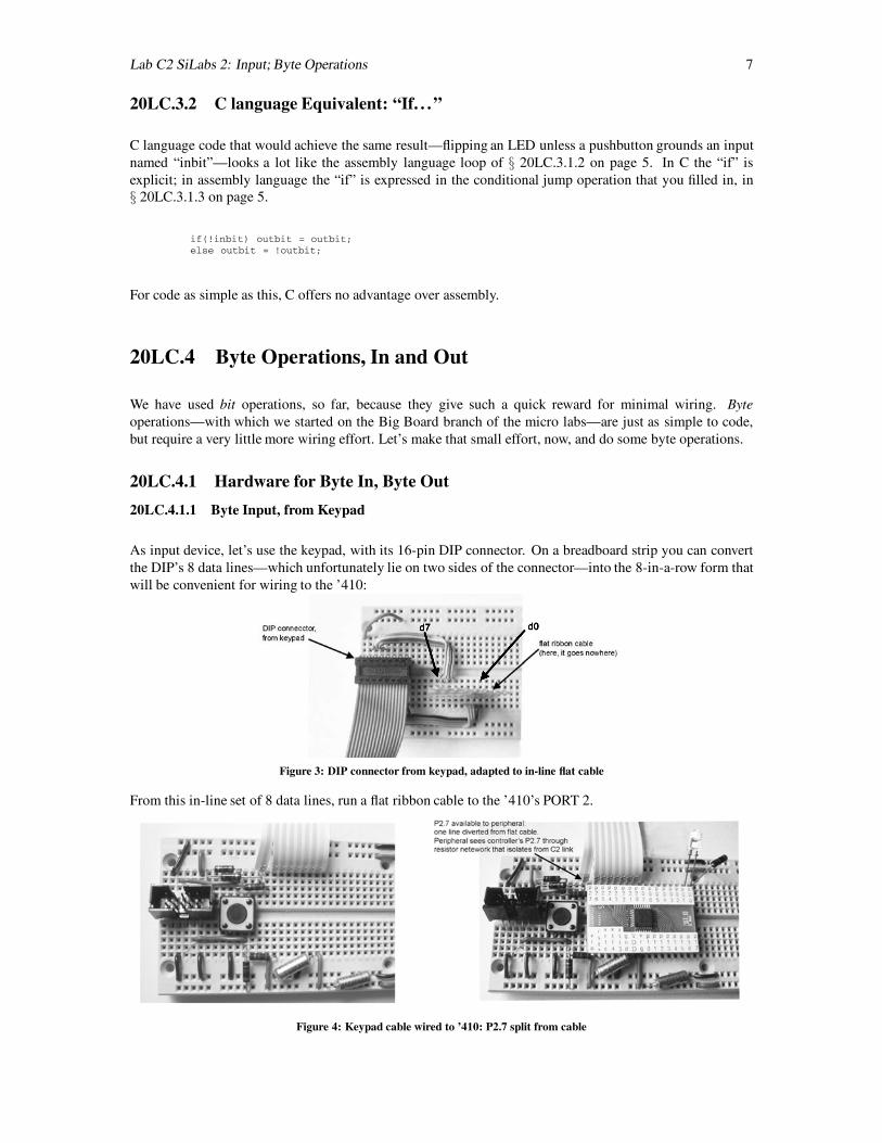
From this in-line set of 8 data lines, run a flat ribbon cable to the ’410’s PORT 2.
Figure 4: Keypad cable wired to ’410: P2.7 split from cable
8 Lab C2 SiLabs 2: Input; Byte Operations
The D7 line on the cable, you’ll notice, comes not from the ’410’s P2.7 but from the far end of the C2-neutralizing resistive network described in Lab SiLabs µ 1.
20LC.4.1.2 Keypad In, Byte Display Out
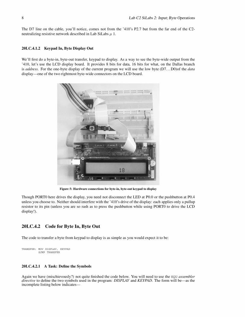
We’ll first do a byte-in, byte-out transfer, keypad to display. As a way to see the byte-wide output from the’410, let’s use the LCD display board. It provides 8 bits for data, 16 bits for what, on the Dallas branchis address. For the one-byte display of the current program we will use the low byte (D7. . .D0)of the datadisplay—one of the two rightmost byte-wide connectors on the LCD board.
Figure 5: Hardware connections for byte-in, byte-out keypad to display
Though PORT0 here drives the display, you need not disconnect the LED at P0.0 or the pushbutton at P0.4unless you choose to. Neither should interfere with the ’410’s drive of the display: each applies only a pullupresistor to its pin (unless you are so rash as to press the pushbutton while using PORT0 to drive the LCDdisplay!).
20LC.4.2 Code for Byte In, Byte Out
The code to transfer a byte from keypad to display is as simple as you would expect it to be:
TRANSFER: MOV DISPLAY, KEYPADSJMP TRANSFER
20LC.4.2.1 A Task: Define the Symbols
Again we have (mischievously?) not quite finished the code below. You will need to use the EQU assemblerdirective to define the two symbols used in the program: DISPLAY and KEYPAD. The form will be—as theincomplete listing below indicates—
Lab C2 SiLabs 2: Input; Byte Operations 9
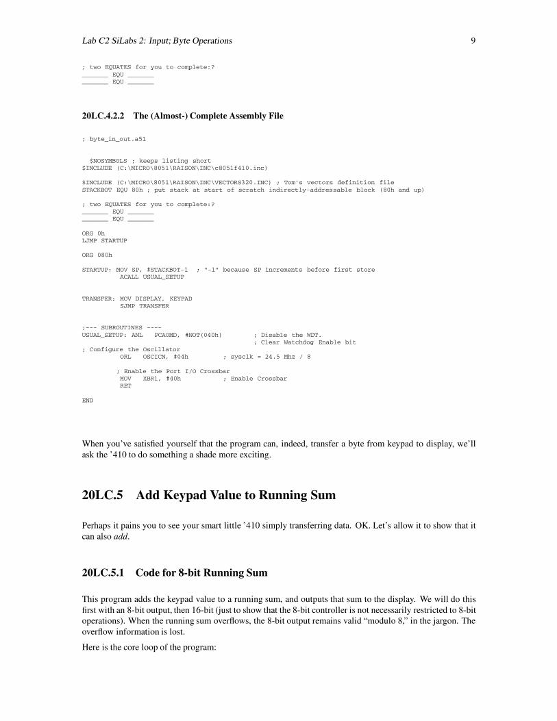
; two EQUATES for you to complete:?_______ EQU ______________ EQU _______
20LC.4.2.2 The (Almost-) Complete Assembly File
; byte_in_out.a51
$NOSYMBOLS ; keeps listing short$INCLUDE (C:\MICRO\8051\RAISON\INC\c8051f410.inc)
$INCLUDE (C:\MICRO\8051\RAISON\INC\VECTORS320.INC) ; Tom’s vectors definition fileSTACKBOT EQU 80h ; put stack at start of scratch indirectly-addressable block (80h and up)
; two EQUATES for you to complete:?_______ EQU ______________ EQU _______
ORG 0hLJMP STARTUP
ORG 080h
STARTUP: MOV SP, #STACKBOT-1 ; "-1" because SP increments before first storeACALL USUAL_SETUP
TRANSFER: MOV DISPLAY, KEYPADSJMP TRANSFER
;--- SUBROUTINES ----USUAL_SETUP: ANL PCA0MD, #NOT(040h) ; Disable the WDT.
; Clear Watchdog Enable bit; Configure the Oscillator
ORL OSCICN, #04h ; sysclk = 24.5 Mhz / 8
; Enable the Port I/O CrossbarMOV XBR1, #40h ; Enable CrossbarRET
END
When you’ve satisfied yourself that the program can, indeed, transfer a byte from keypad to display, we’llask the ’410 to do something a shade more exciting.
20LC.5 Add Keypad Value to Running Sum
Perhaps it pains you to see your smart little ’410 simply transferring data. OK. Let’s allow it to show that itcan also add.
20LC.5.1 Code for 8-bit Running Sum
This program adds the keypad value to a running sum, and outputs that sum to the display. We will do thisfirst with an 8-bit output, then 16-bit (just to show that the 8-bit controller is not necessarily restricted to 8-bitoperations). When the running sum overflows, the 8-bit output remains valid “modulo 8,” in the jargon. Theoverflow information is lost.
Here is the core loop of the program:

10 Lab C2 SiLabs 2: Input; Byte Operations
Transfer: MOV A, RUN_SUM ; recall running sumADD A, KEYPAD ; form new sum. Note that result lands in AMOV RUN_SUM, A ; ...save itMOV DISPLAY, A ; ...and show itACALL DELAYSJMP Transfer ; ...forever
To make sense of this code, you need to recall that the result of ADD goes to the accumulator, the A register.So, each pass through the loop updates both the running sum (RUN SUM) and the display.
As you try this program, you might start by setting up 01h on the keypad. The summing then amounts just tocontinually incrementing, of course. When you’re feeling more adventurous, try keypad value FFh.
; keysum_8bit.a51 shows sum of keypad and running sum; decimal adjust after initial binary display;
$NOSYMBOLS ; keeps listing short$INCLUDE (C:\MICRO\8051\RAISON\INC\c8051f410.inc)
STACKBOT EQU 80h ; put stack at start of scratch indirectly-addressable block (80h and up)
DISPLAY EQU P1 ; so-called Data byte on LCD boardKEYPAD EQU P2RUN_SUM EQU R7 ; this choice is arbitrary
DELAY_MULTIPLIER EQU 08h ; about half-second delay, at div-by-8 clock rate
ORG 0hLJMP STARTUP
ORG 080h
STARTUP: MOV SP, #STACKBOT-1
ACALL USUAL_SETUP
; Initialize running sumCLR A
MOV RUN_SUM, A ; clear running sum
Transfer: MOV A, RUN_SUM ; recall running sumADD A, KEYPAD ; form new sum
; DA A ; For decimal sum--try after watching binary additionMOV RUN_SUM, A ; ...save itMOV DISPLAY, A ; ...and show itACALL DELAYSJMP Transfer ; ...forever
;----SUBROUTINES ----DELAY: PUSH ACC ; save the registers that this routine will mess up
PUSH BPUSH 4 ; this saves register R4--in the zeroth set of registers
MOV A,#0 ; maximize two delay values (0 is max because dec before test)MOV B,#0 ; ...and second loop delay valueMOV R4, #DELAY_MULTIPLIER ; a more general way to specify delayu: this multiplies the 64K other loops
INNERLOOP: DJNZ B, INNERLOOP ; count down innermost loop, till inner hits zeroDJNZ ACC,INNERLOOP ; ...then dec second loop, and start inner again.DJNZ R4, INNERLOOP ; now, with second at zero, decrement the outermost loop
POP 4 ; restore saved registersPOP BPOP ACCRET ; back to main program
USUAL_SETUP: ; Disable the WDT.ANL PCA0MD, #NOT(040h) ; Clear Watchdog Enable bit
; Configure the Oscillator;ORL OSCICN, #04h ; sysclk = 24.5 Mhz / 8, for lower power
; Enable the Port I/O CrossbarMOV XBR1, #40h ; Enable Crossbar
RETEND
Lab C2 SiLabs 2: Input; Byte Operations 11
20LC.5.1.1 Delay Routine Marginally Amended
We made one small change to the Delay routine, in § 20LC.5.1 on page 9: rather than fix the duration ofDelay within that subroutine, as we did earlier (for example, in § 20LC.2 on page 2), we set the value of thedelay multiplier at the head of the program. The multiplier, in this routine, determines how many times the16-bit countdown loop will be repeated (each loop taking about 80ms).
This change makes Delay more versatile, and also illustrates a point concerning the design of programs: it’sa good idea to initialize constants up at the start of a program, where they are easy to see and to change. Ifyou decide to change the Delay duration from 1 second to two, you don’t want to have to search the programlisting so as to locate the place where that duration is set.
20LC.5.1.2 8-bit Output Amended to Decimal Form
Binary addition makes efficient use of the running-sum and keypad bytes, permitting use of all 256 com-binations. But when a display is intended for humans—with their many fingers, and their peculiar decimalcounting system—a decimal output often is preferable. The 8051 knows how to restrict its output to thedecimal values, so long as we give it keypad values that also are limited to decimal values.
All we need do, in order to see this behavior, is to un-comment the instruction “DA” in the program of§ 20LC.5.1 on page 9. DA (“Decimal Adjust”) operates on the Accumulator (A register), noting when a“half-carry” from the low nybble occurs. So, for example, if A holds the value 09h and we add one, in binarythe next value would be 0Ah. But DA notes the “half-carry” and amends the accumulator value appropriately:the “half-carry” tells the processor to roll over the low nybble to 0 while incrementing the high nybble. Theresult thus becomes 10h, the decimal count, indeed, that must succeed 09h.
We should note what DA cannot do: it cannot transform a hexadecimal value to decimal; it works properlyonly after an operation, like ADD, that affects flags appropriately—particularly, the half-carry flag. Thedetails of flag effects appear in the descriptions of each processor operation, in the 8051 instruction setreference.
The first time you do an operation that depends on flag behaviors, you would be wise to check this behaviorin the instruction set reference. INC (increment) and DEC affect no flags, for example. That is a behaviorone could not anticipate from any principle that we can perceive.
It is, of course, possible to do a generalized conversion from a binary value to decimal. But this process callsfor a multi-step algorithm, and is neither simple nor quick. DA neatly covers the present task.
20LC.5.2 16-bit Running Sum
Now let’s allow the 8051 show that it can handle values larger than one byte. We don’t often ask it to do so—and, in fact, are inclined to keep its computation tasks minimal. But at a price of speed, an 8-bit processorcan concatenate operations so as to operate on values larger than what fits in a single byte.
Here, we will keep the running sum to 16 bits rather than 8, and we will display it on the LCD board using fourhex digits rather than two, as for the byte sum. We’ll exercise this hardware with an amended running-sumprogram.
12 Lab C2 SiLabs 2: Input; Byte Operations
20LC.5.2.1 Hardware for 16-bit Display
20LC.5.2.2 Two-Byte Output, to Display
On the LCD board you will find two 8-bit ‘data’ connectors, labelled “D15. . .D8” and “D7. . .D0.” These willaccept your micro’s 16-bit output. Set the right-hand DIP switch to “16” rather than “8mux.” This makes thetwo 8-bit ports independent. (“8mux,” in contrast, would merge the inputs, so that they could be separatedonly by the separate assertions of the two latch ENABLE*s. That is an option you will not use, here.)
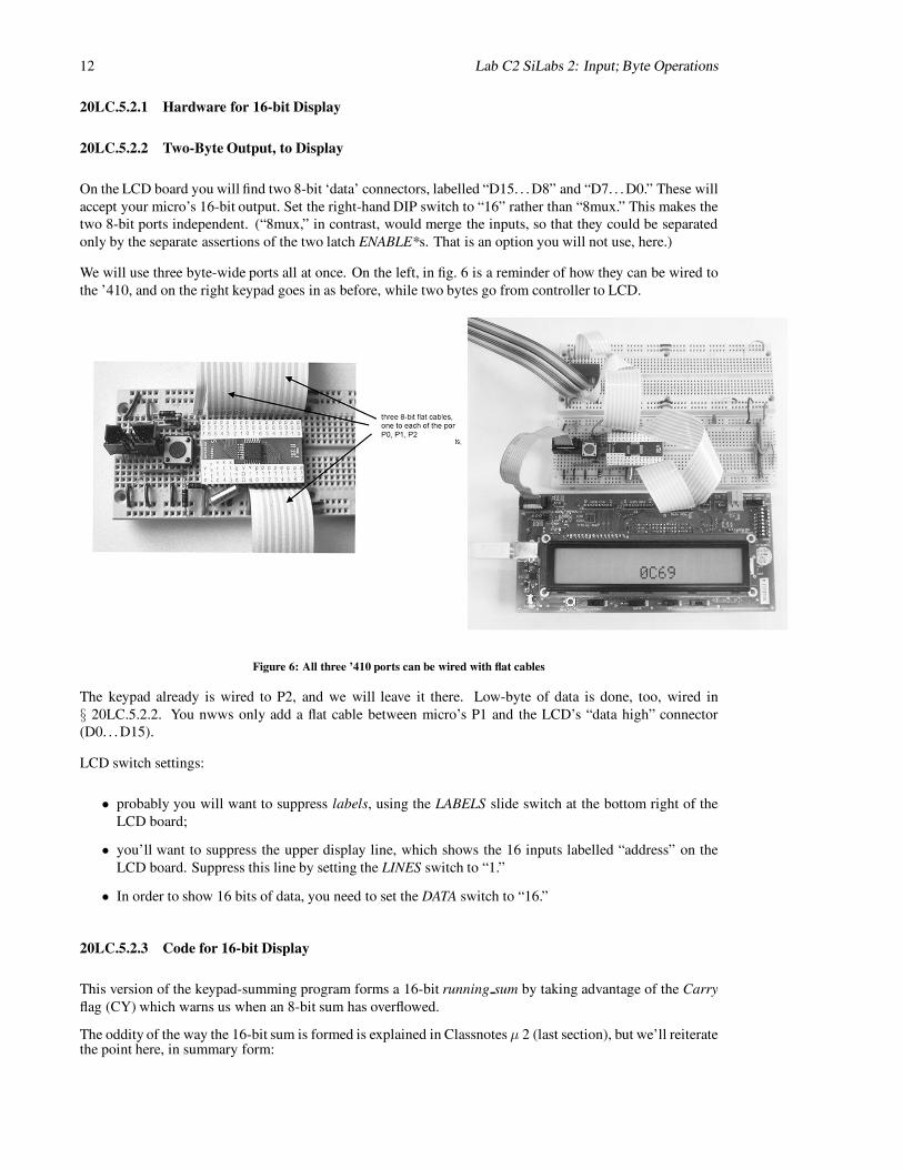
We will use three byte-wide ports all at once. On the left, in fig. 6 is a reminder of how they can be wired tothe ’410, and on the right keypad goes in as before, while two bytes go from controller to LCD.
Figure 6: All three ’410 ports can be wired with flat cables
The keypad already is wired to P2, and we will leave it there. Low-byte of data is done, too, wired in§ 20LC.5.2.2. You nwws only add a flat cable between micro’s P1 and the LCD’s “data high” connector(D0. . .D15).
LCD switch settings:
• probably you will want to suppress labels, using the LABELS slide switch at the bottom right of theLCD board;
• you’ll want to suppress the upper display line, which shows the 16 inputs labelled “address” on theLCD board. Suppress this line by setting the LINES switch to “1.”
• In order to show 16 bits of data, you need to set the DATA switch to “16.”
20LC.5.2.3 Code for 16-bit Display
This version of the keypad-summing program forms a 16-bit running sum by taking advantage of the Carryflag (CY) which warns us when an 8-bit sum has overflowed.
The oddity of the way the 16-bit sum is formed is explained in Classnotes µ 2 (last section), but we’ll reiteratethe point here, in summary form:
Lab C2 SiLabs 2: Input; Byte Operations 13
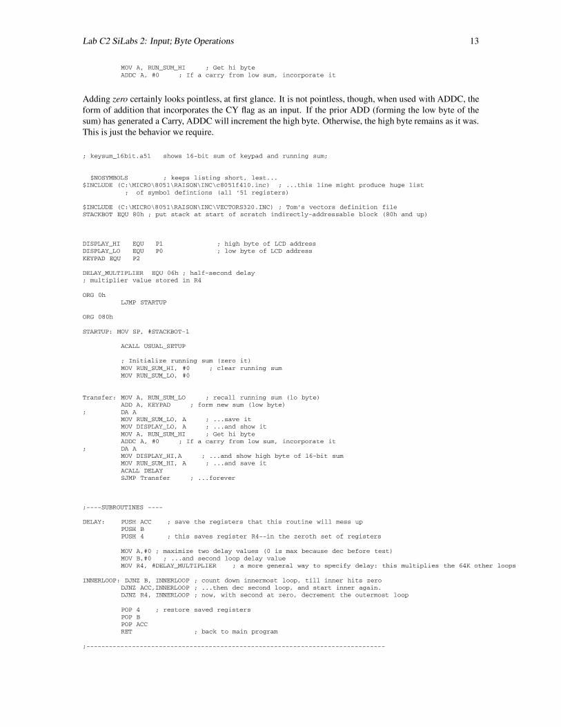
MOV A, RUN_SUM_HI ; Get hi byteADDC A, #0 ; If a carry from low sum, incorporate it
Adding zero certainly looks pointless, at first glance. It is not pointless, though, when used with ADDC, theform of addition that incorporates the CY flag as an input. If the prior ADD (forming the low byte of thesum) has generated a Carry, ADDC will increment the high byte. Otherwise, the high byte remains as it was.This is just the behavior we require.
; keysum_16bit.a51 shows 16-bit sum of keypad and running sum;
$NOSYMBOLS ; keeps listing short, lest...$INCLUDE (C:\MICRO\8051\RAISON\INC\c8051f410.inc) ; ...this line might produce huge list
; of symbol defintions (all ’51 registers)
$INCLUDE (C:\MICRO\8051\RAISON\INC\VECTORS320.INC) ; Tom’s vectors definition fileSTACKBOT EQU 80h ; put stack at start of scratch indirectly-addressable block (80h and up)
DISPLAY_HI EQU P1 ; high byte of LCD addressDISPLAY_LO EQU P0 ; low byte of LCD addressKEYPAD EQU P2
DELAY_MULTIPLIER EQU 06h ; half-second delay; multiplier value stored in R4
ORG 0hLJMP STARTUP
ORG 080h
STARTUP: MOV SP, #STACKBOT-1
ACALL USUAL_SETUP
; Initialize running sum (zero it)MOV RUN_SUM_HI, #0 ; clear running sumMOV RUN_SUM_LO, #0
Transfer: MOV A, RUN_SUM_LO ; recall running sum (lo byte)ADD A, KEYPAD ; form new sum (low byte)
; DA AMOV RUN_SUM_LO, A ; ...save itMOV DISPLAY_LO, A ; ...and show itMOV A, RUN_SUM_HI ; Get hi byteADDC A, #0 ; If a carry from low sum, incorporate it
; DA AMOV DISPLAY_HI,A ; ...and show high byte of 16-bit sumMOV RUN_SUM_HI, A ; ...and save itACALL DELAYSJMP Transfer ; ...forever
;----SUBROUTINES ----
DELAY: PUSH ACC ; save the registers that this routine will mess upPUSH BPUSH 4 ; this saves register R4--in the zeroth set of registers
MOV A,#0 ; maximize two delay values (0 is max because dec before test)MOV B,#0 ; ...and second loop delay valueMOV R4, #DELAY_MULTIPLIER ; a more general way to specify delay: this multiplies the 64K other loops
INNERLOOP: DJNZ B, INNERLOOP ; count down innermost loop, till inner hits zeroDJNZ ACC,INNERLOOP ; ...then dec second loop, and start inner again.DJNZ R4, INNERLOOP ; now, with second at zero, decrement the outermost loop
POP 4 ; restore saved registersPOP BPOP ACCRET ; back to main program
;------------------------------------------------------------------------------
14 Lab C2 SiLabs 2: Input; Byte Operations
USUAL_SETUP: ; Disable the WDT.ANL PCA0MD, #NOT(040h) ; Clear Watchdog Enable bit
; Configure the Oscillator;ORL OSCICN, #04h ; sysclk = 24.5 Mhz / 8, for lower power
; Enable the Port I/O CrossbarMOV XBR1, #40h ; Enable Crossbar
RETEND
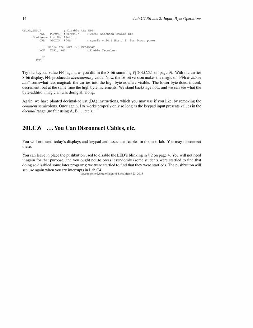
Try the keypad value FFh again, as you did in the 8-bit summing (§ 20LC.5.1 on page 9). With the earlier8-bit display, FFh produced a decrementing value. Now, the 16-bit version makes the magic of “FFh as minusone” somewhat less magical: the carries into the high byte now are visible. The lower byte does, indeed,decrement; but at the same time the high byte increments. We stand backstage now, and we can see what thebyte-addition magician was doing all along.
Again, we have planted decimal-adjust (DA) instructions, which you may use if you like, by removing thecomment semicolons. Once again, DA works properly only so long as the keypad input presents values in thedecimal range (no fair using A, B. . . , etc.).
20LC.6 . . . You Can Disconnect Cables, etc.
You will not need today’s displays and keypad and associated cables in the next lab. You may disconnectthese.
You can leave in place the pushbutton used to disable the LED’s blinking in § 2 on page 4. You will not needit again for that purpose, and you ought not to press it randomly (some students were startled to find thatdoing so disabled some later programs; we were startled to find that they were startled). The pushbutton willsee use again when you try interrupts in Lab C4.
lab controller2 headerfile july14.tex; March 23, 2015
Index
ACCvs “A” SiLabs (lab), 3
ADDC (lab), 12
CALLSiLabs (lab), 2
DA (lab), 11
EQU (lab), 8
IFbit test equivalents (lab), 7
POPSiLabs (lab), 3
PUSHSiLabs (lab), 3
subroutineSiLabs (lab), 2
15