journal of reliable powerv1n2 a7 - selinc.com.br · “applying iec 61850 to real life:...
TRANSCRIPT

Journal of Reliable PowerVolume 1 Number 2 October 2010
$12.00

Introduction
Automated Event Retrieval Reduces Operating Costs Todd Rosenberger, David Prestwich, Matthew Watkins, and Mark Weber (2008)
Using Information From Relays to Improve the Power System—Revisited David Dolezilek (2010)
Implementing Distribution Automation and Protection Karl Zimmerman and Mike Collum (2003)
Case Study of a Large Transmission and Distribution Substation Automation Project David Dolezilek (1999)
Proven Drop-In Control House Turnkey Solution for Total Protection, Monitoring, Automation, and Control of T&D Substations: A Case Study in Justification and Implementation Brian McDermott, David Dolezilek, and Timothy Tibbals (2001)
Apply Radios to Improve the Operation of Electrical Protection Shankar V. Achanta, Brian MacLeod, Eric Sagen, and Henry Loehner (2010)
IEC 61850: What You Need to Know About Functionality and Practical Implementation David Dolezilek (2005)
IEC 61850 – What It Can and Cannot Offer to Traditional Protection Schemes Daqing Hou and David Dolezilek (2008)
IEC 61850 – More Than Just GOOSE: A Case Study of Modernizing Substations in Namibia Dorran D. Bekker, Peter Diamandis, and Timothy Tibbals (2010)
Ten Tips for Improving the Security of Your Assets Edmund O. Schweitzer, III (2009)
Communications and Protocols Bibliography
SEL University Training Options
Modern Solutions for Protection, Control, and Monitoring of Electric Power SystemsOrdering Information
Journal of Reliable Power Volume 1 Number 2 October 2010
2
4
12
25
31
43
51
63
72
83
90
92
98
99
Timothy Tibbals received his B.S. in electrical engineering from Gonzaga University in 1989. After graduation, he joined Schweitzer Engineering Laboratories, Inc. (SEL) as an application engineer, performing system studies and relay testing. He also worked as a development engineer and as part of the development team for many of the communications features and functions of SEL products. He subsequently worked as an application engineer for protection, integration, and automation products, assisting customers through product training, seminars, and phone support. He also served as the automation services supervisor in the SEL Engineering Services Division for several years before returning to the Research and Development Division as a product engineer for automation and communications engineering products. He is currently a senior automation system engineer in the Sales and Customer Service Division.
Issue Editor

2 | Journal of Reliable Power
This second issue of the Journal of Reliable Power fea-tures technical papers that focus on communications
and protocols. With the introduction of microprocessor-based relay technology more than 25 years ago came the idea that a protective relay could do much more than protect the power system. Early microprocessor-based relay designs integrated a wealth of new functions, rang-ing from sequential events recording and fault location to metering, multiple settings groups, and communications. Before communications grew into an access mechanism for the additional information these relays could provide, its function in early microprocessor-based relays was pri-marily as a user-interface feature to configure protection functionality.
Improved fault location was one of the primary features that influenced the industry’s adoption of microprocessor-based relays. Interestingly, it was the communication of this fault location data out of the protection relay that truly made the technology useful, as documented in “Auto-mated Event Retrieval Reduces Operating Costs.”
Early systems required the protection engineer or relay technician to locally communicate with the relay using simple ASCII terminals to access these data. Soon after the introduction of the digital microprocessor-based relay, SEL developed other products that could be used to either access relay data remotely via dial-up modem or with an SEL Protective Relay Terminal Unit (PRTU). Microprocessor relays could also provide data to existing analog Remote Terminal Units (RTUs) using the SEL-DTA Display Transducer Adaptor. “Using Information From Relays to Improve the Power System—Revisited” demonstrates the methods then available to leverage these data features and information.
Application of these relay data to the existing serial communications made it clear that optimization was needed to increase data update rates to remote commu-nications systems. This need led to the invention of SEL Fast Messaging protocol (1994), which was developed to speed the transfer of relay data to remote devices while maintaining the separation of protection functionality and deterministic operation from data communications. Fast message protocol was initially applied to data transfer
between the SEL relay and SEL-DTA but soon found its way into new communications processor products, such as the SEL-2020. These new communications methods opened the door for inventive users to create new ways of improving the substation control and automation system (see “Case Study of a Large Transmission and Distribu-tion Substation Automation Project”).
The SEL-2020 Communications Processor, intro-duced in 1995, allowed digital data from the relay to be concentrated from multiple relays and then communicated to SCADA using a single serial communications channel. With the data already in digital form from the relay, the communications processor only needed to translate this information to other industry standard protocols, such as DNP3 and Modbus®. The SEL-2020 also allowed engi-neering access to relays, leveraging the single serial con-nection to provide both SCADA and engineering access.
Improving communications for protection functions, specifically for pilot protection schemes, was becoming increasingly important. To address this need, SEL devel-oped a new protocol, Mirrored Bits® communications, as an alternative to traditional analog protection communi-cations equipment and brought this functionality directly into the microprocessor-based protection relay (see “Implementing Distribution Automation and Protection”).
In 2002, SEL was the first to include synchronized phasor measurement capability in microprocessor-based protective relays. This measurement feature, accompa-nied by the means to communicate synchrophasors using the IEEE C37.118 protocol, opened new possibilities for the application of synchrophasors in both local and wide-area protection and control (see “Real-Time Synchropha-sor Applications for Wide-Area Protection, Control, and Monitoring” online at www.selinc.com).
The combination of improved data communications and relay-to-relay logic communications enabled the sim-plification of substation panel design and wiring. This simplification also provided cost reductions to users both in installation and design and in asset management with the availability of real-time equipment monitoring (see “Proven Drop-In Control House Turnkey Solution for
Introduction

Introduction | 3
Total Protection, Monitoring, Automation, and Control of T&D Substations: A Case Study in Justification and Implementation”).
In many situations radio systems have become an economical choice for relay protection and data commu-nications, compared to traditional methods that use micro-wave communications systems, optical fiber, leased tele-phone line, and other communications methods. “Apply Radios to Improve the Operation of Electrical Protection” is a tutorial on the application, installation, and cost ben-efits of radio systems.
As the available microprocessor capability of protec-tive relays improved over time, communications networks experienced similar advancements. Ethernet-based com-munication became standard in office computers, while advancements in Ethernet hardware and fiber-optic com-munication enabled the use of Ethernet in substations. This new substation Ethernet communication was expected to transport all the same data for SCADA and control that serial communications methods had provided in the past. Initially, Ethernet was added to existing systems by incor-porating it into the serial-based communications proces-sors or SCADA gateway products. However, substation data communications requirements soon moved Ethernet communications directly into the protective relay. Relay data and functionality, previously available only via serial connections, were now available via Ethernet.
During this time period, standards work brought substation data communications into a modern object-oriented methodology. The IEC 61850 standard came as the result of this effort and moved data communications into the substation from an anonymous register or object-based format to a self-describing object model approach (see “IEC 61850: What You Need to Know About Func-tionality and Practical Implementation”).
This new standard brought new possibilities and chal-lenges. Protection engineers now needed to understand communications networks because of the coexistence of protection, automation, and SCADA communication. IEC 61850 GOOSE (Generic Object Oriented Substa-tion Event) messages, designed specifically for protection applications, are similar to Mirrored Bits communica-tions, but, rather than point-to-point serial communica-tions, they are point-to-multipoint across the Ethernet net-work. These new messages require substation networks to be as reliable as the physical connections they replace and that other network communications traffic does not impact them.
These network management concepts are not new, but they are now being applied by new users of the sub-station network, protection engineers and communica-tions engineers alike. Understanding these new capabili-ties and available technology is crucial for the successful application of Ethernet and IEC 61850 in the substation of today. “IEC 61850—What It Can and Cannot Offer to Traditional Protection Schemes” and “IEC 61850—More Than Just GOOSE: A Case Study of Modernizing Substa-tions in Namibia,” both illustrate these points. “Applying IEC 61850 to Real Life: Modernization Project for 30 Electrical Substations,” a technical paper available on the SEL website, is another source of information.
Another challenge is the application of these commu-nications between substations and between substations and control centers. Wide-area dependable communications are needed today for new protection, control, and moni-toring applications. The SEL ICON™ provides depend-able, deterministic, and secure communications for these critical infrastructure applications of the electric power system. Visit www.selinc.com/ICON for more detailed information.
Any discussion on communications today must include the issue of security. From the very first days of our company, SEL has recognized the need for secu-rity and has incorporated password and access level protection in all products. “Ten Tips for Improving the Security of Your Assets” highlights specific ways to practice sensible cybersecurity. As security require-ments have changed, SEL has developed new prod-ucts and methods to address these needs; the SEL-3021 Serial Encrypting Transceiver and SEL-3620 Ethernet Security Gateway are two examples. For detailed infor-mation about SEL security products and services, please visit www.selinc.com/securecommunications and www.selinc.com/cybersecurity.
Today’s engineer is challenged with a broadening range of products and technologies. Mastering these chal-lenges presents tremendous opportunities to make the electric power system safer, more reliable, and more eco-nomical.
If you have comments or suggestions, please email [email protected] or share your thoughts with our edi-tors by phone at +1.509.332.1890. For more information and for electronic versions of this and past issues, visit www.selinc.com/literature.

4 | Journal of Reliable Power
Automated Event Retrieval Reduces Operating Costs
Todd Rosenberger, Oncor Electric Delivery David Prestwich, Matthew Watkins, and Mark Weber, Schweitzer Engineering Laboratories, Inc.
Abstract—In August 2007, Oncor Electric Delivery began installing a centralized automatic relay event retrieval and indexing system. With over 400 transmission substations and 3,600 relays capable of recording critical event data, Oncor wanted to improve their existing process of dispatching a technician to a substation each time a critical event occurred that needed further review. Beyond the obvious operating cost savings associated with retrieving critical event data, Oncor had additional ideas for using the data.
Analyzing every event file where the relay sensed a fault condition and the breaker cleared it is an opportunity to gauge the health of the protection and control system. Relays that generate power system event reports ranging from a few cycles to a few seconds provide the opportunity to see fault inception, relay response, and breaker operation. To analyze every event file, Oncor developed a process to retrieve event records from their protective relays.
It is often assumed that automatic event collection systems require installation of new and potentially costly communications equipment for high-speed data transfer. Additionally, proposed North American Electric Reliability Cooperation (NERC) Critical Infrastructure Protection (CIP) reliability standards are often interpreted as mandates to apply potentially expensive and complex firewalls or software security to associated communica-tions channels. Considering the high costs of applying this equipment or software across 400 transmission substations, Oncor engineers immediately recognized that they could obtain significant cost savings if the recommended security guidelines and event collection requirements could be satisfied using existing installed communications equipment. Oncor met this goal with minimal hardware installations. This paper highlights the installed system and provides a summary of installation and operational benefits.
I. BACKGROUND Oncor Electric Delivery (Oncor) is an electric distribution
and transmission business that provides power to more than three million homes and businesses throughout east, west, and north central Texas. Oncor has more than 115,000 miles of transmission and distribution lines and 900 substations throughout the state.
In the 1990s, Oncor began deploying digital fault recorders (DFRs) in their substations. In January 1997, due to the amount of information coming from the DFRs and in order to address the need to efficiently analyze, categorize, and prioritize DFR records, Oncor finalized a software development contract with Texas A&M University. The project included the development of automated DFR event classification logic and universal viewing software. Reference [1] highlights Oncor’s initial system.
Over the last 10 years, the DFR program has grown from 80 to over 230 data acquisition units with automatic DFR event retrieval. Fig. 1 shows the present system. Initially, the system monitored between 32 and 64 analog channels and 64 to 128 digital channels at each location. Today, Oncor has nearly doubled the analog and digital data channels at each site. Of the 235 DFRs, over 30 are dual purpose and provide Oncor with transient and long-term recording capabilities.
Distribution Substations
Generation Switchyards
Transmission Switchyards
DFR Event Classification System
High - Medium - Low Email
Cell Phones and Pagers
Engineering Access
Increased Asset Utilization - O&M Labor - Minimum Additional Hardware
Notification
150 DFR Locations
Fig. 1. Oncor Electric Delivery Classification System
While Oncor continues to make software improvements to the event classification software, the overall event priority criteria remain the same.
• High priority: undesirable operations • Medium priority: events from correct operations or
reclose failure • Low priority: manually triggered, switching
operations, or remote fault events See Fig. 2 for additional details on event classification [1].
Relay Slow ClearingBreaker FailureBreaker Slow ClearingBreaker RestrikeCarrier Misoperation
High
Correct OperationRecloser FailureLine Lockout
Medium
No OperationManual TriggerSwitching OperationsRemote Faults
Low
Fig. 2. Event Priority Classification
Oncor uses the DFR report data to help schedule maintenance or review relay settings. Fig. 3 shows three months of high-priority DFR records that alerted Oncor personnel to issues that resulted in an unexpected operation, such as delayed relay trip time or required carrier mainte-nance.
Automated Event Retrieval Reduces Operating Costs | 5
Fig. 3. High-Priority Event Records
Looking at the details of each specific event, Oncor engineers are able to determine the root cause and make appropriate changes to improve future operation. The event report in Fig. 4 resulted from a high-priority event classification (Relay Slow Clearing due to carrier delay). Engineers were able to schedule carrier maintenance to ensure the problem would not occur again.
Fig. 4. High-Priority Event Record
Annually, the system automatically retrieves and analyzes over 12,000 events. The system automatically diagnoses the following:
• Fault location • Power grid impact • Event root cause • Breaker problems • CT and PT instrumentation issues
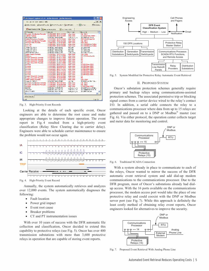
With over 10 years of success with the DFR automatic file collection and classification, Oncor decided to extend this capability to protective relays (see Fig. 5). Oncor has over 400 transmission substations with more than 3,600 protective relays in operation that are capable of storing event reports.
Distribution Substations
Generation Switchyards
Transmission Switchyards
DFR Event Classification SystemHigh - Medium - Low Email
Cell Phones and Pagers
Engineering Access
Notification
150 DFR Locations
Communications Processor,SCADA RTU Functions,
and Remote Access
Transmission Line Retrofit
Panels
Relay Providers
Distribution Substations
Protective Relay Master Station
Fig. 5. System Modified for Protective Relay Automatic Event Retrieval
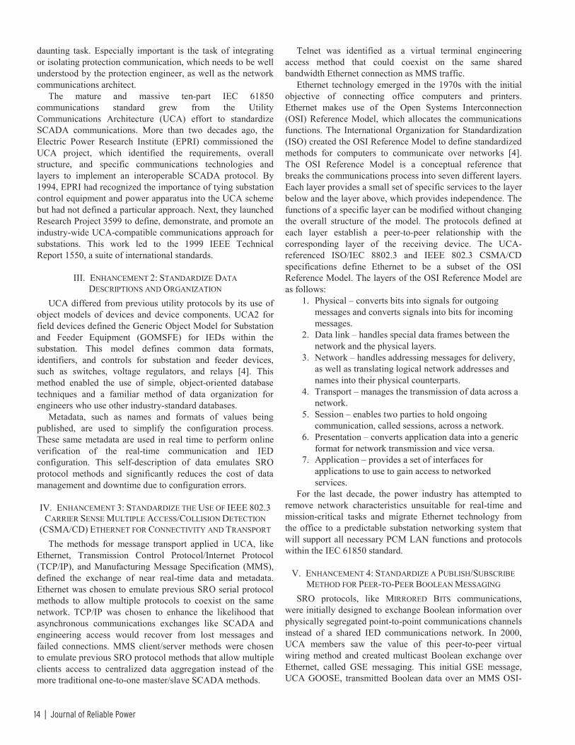
II. PROPOSED SYSTEM Oncor’s substation protection schemes generally require
primary and backup relays using communications-assisted protection schemes. The associated permissive trip or blocking signal comes from a carrier device wired to the relay’s contact I/O. In addition, a serial cable connects the relay to a communications processor where data from up to 15 relays are gathered and passed on to a DNP or Modbus® master (see Fig. 6). Via either protocol, the operation center collects target and meter data for monitoring and control.
Communications Processor
Protective Relays (15)
RTU
DNP or Modbus
15
Fig. 6. Traditional SCADA Connection
With a system already in place to communicate to each of the relays, Oncor wanted to mirror the success of the DFR automatic event retrieval system and add dial-up modem communications to the communications processor. Due to the DFR program, most of Oncor’s substations already had dial-up access. With the 16 ports available on the communications processor, the modem access port would take the place of one protective relay and could coexist with the DNP or Modbus server port (see Fig. 7). While this approach is definitely the least costly method of obtaining relay event reports, Oncor engineers looked for alternatives to improve the security.
Communications Processor
Protective Relays (14)
RTU
DNP or Modbus
External Modem
Analog Phone Line
14
Fig. 7. Proposed Event Retrieval With Analog Phone Line

6 | Journal of Reliable Power
Oncor is underway to expand Ethernet communications to their substations. The first two test sites went online in October 2007, and Oncor wanted to make sure this proposed system could adapt to Ethernet communications. Using the communications processor, they could either communicate by adding a direct Ethernet connection or by using a serial-to-Ethernet transceiver (see Fig. 8). Oncor chose the transceiver. In addition to being more economical than adding an Ethernet port, the serial-to-Ethernet transceiver would later provide security consistent with the dial-up application and simplify settings management.
Communications Processor
Ethernet Router
Serial-to-Ethernet Converter
Intranet
Protective Relays (14)
14
RTU
DNP or Modbus
Fig. 8. Proposed Event Retrieval With Ethernet Connection
On the master station side, Oncor used a configuration similar to the DFR system. External modems connect the master station computer to the remote locations. The master station uses a static IP address so the communications processors that are connected via serial-to-Ethernet transceivers know through which port to send the data. The automatic event classification and archiving software communicates to the master station. Once the master station retrieves the events, the classification program, similar to the program already in place for DFR records, assigns priority to the events (see Fig. 9). Oncor met their goal of integrating 20 substations in 2007 and will complete the remaining substation installations in 2008.
Event Classification
Archiving
External Modem
Analog Phone Line
Master Station
Ethernet
Automatic Event Retrieval
Software
Fig. 9. Master Station Connections
While this system mimics the proven communications system of the DFR program, Oncor knew NERC/CIP Reliability Standards specified requirements for the electronic security perimeter associated with dial-up and Ethernet access to critical cyber assets.
III. HOW NERC/CIP COULD IMPACT THIS AUTOMATIC EVENT RETRIEVAL PROCESS
On January 16, 2006, NERC proposed the following CIP Reliability Standards [2]:
CIP-002–Critical Cyber Asset Identification CIP-003–Security Management Controls CIP-004–Personnel and Training
CIP-005–Electronic Security Perimeters CIP-006–Physical Security CIP-007–Systems Security Management CIP-008–Incident Reporting and Response Planning CIP-009–Recovery Plans for Critical Cyber Assets
CIP standards 002, 003, 005, and 007 directly impact the implementation of dial-up modem and Ethernet access to protective relays. Oncor expects to use collected event data to aid in compliance with future NERC relay maintenance standards. Oncor has implemented and documented a plan to protect critical cyber assets in order to comply with CIP-003, Requirement 4. This plan is confidential; however, we will discuss one element of the plan for improving security.
A. CIP-002–Critical Cyber Asset Identification CIP-002 provides definitions for critical assets, cyber
assets, and critical cyber assets. In a system with dial-up access, the communications processor could be subject to CIP-002, while the relays are not. Although the relays have routable protocols, they were not required for this application where all communications use nonroutable protocols. Distance relays commonly use communications-aided protection schemes; however, by definition, due to communications be-tween discrete electronic security perimeters, they are exempt from CIP-002. To provide “defense in depth” [3] to their protective relays, utilities take additional steps as outlined in [4]. In contrast, the DFRs may not be affected by these NERC/CIP standards—depending on how your company views the DFR data.
B. CIP-003–Security Management Controls CIP-003, Requirements 4 and 5 apply to automatic event
retrieval from protective relays. Requirement 4, Information Protection, requires implementing and documenting a program to identify, classify, and protect information associated with critical cyber assets. Requirement 5 addresses access control. This requirement addresses the need for a program to document and manage access to critical cyber assets. Because Oncor needed dial-up and Ethernet communications in their substations, they looked for an innovative and economical way to limit access to the communications processor (see Section IV), thus meeting the intent of CIP-005, Requirement 2.1.
C. CIP-005–Electronic Security Perimeter CIP-005 details the requirements that define the electronic
security perimeter, monitoring of electronic access, and cyber vulnerability assessment. Clearly, if the communications processor is a critical cyber asset, it needs an electronic security perimeter and additional security to meet these re-quirements. Oncor chose to incorporate existing technology rather than invest in new technology that would add to the overall project cost and complexity.
D. CIP-007–Systems Security Management CIP-007 defines the methods, processes, and procedures
for securing critical cyber assets and other cyber assets within the electronic security perimeter.

Automated Event Retrieval Reduces Operating Costs | 7
IV. ADDING DEFENSE IN DEPTH Oncor improved control access security using the
NOCONN (no connections permitted) function in the communications processor. NOCONN terminates existing connections and blocks requested communications on each individual port. The NOCONN function meets the security standard by aborting transmissions in progress, terminating the receipt of characters, and blocking connections. This communications termination appears the same as a port time out to other connective devices.
Each port in the communications processor contains the NOCONN function. Users enter either a setting to permanently enable or disable the port or a control equation to specify the condition in which NOCONN is used.
Oncor uses the NOCONN solution as one of several defense mechanisms. In the normal state, NOCONN remains on until an event occurs. Once the relay has a new available event, the communications processor turns off NOCONN and allows the modem to dial out or the Ethernet port to connect to the master station. Once the communications processor transfers the event to the master station, the communications processor turns on NOCONN and blocks any external communications. During the outgoing transmission, the communications line is in use and blocks other communica-tions attempts. Users define the specific dial-out number for modem applications or the specific static IP address of the master station for Ethernet applications as part of the communications processor’s set file.
As an additional benefit to this secure system, Oncor engineers have remote engineering access to the protective relays. Oncor accomplished this by modifying the NOCONN logic to accept known remote access to the communications processor. To comply with NERC/CIP reliability standards, Oncor will have to develop strong procedural or technical controls to authorize and log temporary remote access. As with automatic event transmission, other communication is blocked during temporary access.
V. SYSTEM OPERATION The master station contains automatic event retrieval
software. Similar to other relay setting programs, Oncor created a connection directory for each protective relay (Fig. 10). The connection directory includes connection information (modem or Ethernet) for the communications processor and the appropriate port to which the relay is connected.
Fig. 10. Configuring Connection Directory
Once Oncor configures the connection directory, they define the specific event reports that the software extracts from the relay (Fig. 11). Options include standard ASCII-based event reports, compressed event reports, or raw COMTRADE files.
Fig. 11. Selecting Event Collection Options
When the software saves an event report or capture of a user command, it saves the data relative to the end user’s file naming needs (see Fig. 12). This dynamic file naming ability conforms to the recently approved IEEE C37.232 standard [5].
Fig. 12. Available Naming Conventions per C37.232

8 | Journal of Reliable Power
Depending on requirements, the software allows for two modes of operation: polling and listening.
• Polling allows the software to repeat a series of event collections based on time and date intervals.
• Listening places the software in a state to listen for incoming calls from a communications processor on a direct serial, modem, or Ethernet connection.
Due to the number of protective relays on their system, Oncor only enabled the listening mode. The software allows different parameters for serial modem and Ethernet (telnet) commu-nications.
In listening mode, when an event becomes available in the protective relay, the NOCONN function is disabled and the communications processor dials out to the master station. Similarly, if the communications processor uses Ethernet to connect to the master station, the communications processor enables its serial port, allowing the serial-to-Ethernet transceiver to connect to the master station.
The software creates a database of all retrieved records (Fig. 13), and it provides a user interface for viewing each report. Oncor archives the event reports for long-term storage.
Fig. 13. Software Event Viewer
The software supports email notification of new events (Fig. 14). Oncor can set the software to email the event summary or the entire event to predefined individuals. The email contains information similar to the relay event summary, so it can quickly alert the operator of fault magnitudes and distances, allowing quicker power restoration.
Fig. 14. Sample Email Notification
Reference [6] provides additional details on the protective relay, communications processor, and software configuration.
VI. ADDED BENEFITS Beyond collecting event reports, the automatic event
retrieval software also allows user-specified commands. Operators configure up to ten specific commands, and the software stores the relay’s response to each command in a uniquely named text file. Fig. 15 shows the user command configuration dialog. With this configuration, the relay responds with breaker monitoring data (shown in Fig. 16). Once the relay transfers all available event reports to the master station, the software issues and records the response to all user-specified commands.
Fig. 15. Configuring User Commands (Breaker Monitor)
Fig. 16 shows the output for the breaker wear command. It includes information such as electrical and mechanical operating time, accumulated primary current interrupted, and maximum current interrupted.
Fig. 16. Breaker Monitor Report
When analyzing event reports, it is helpful to have sequential events reports (SER). By entering a user-specified

Automated Event Retrieval Reduces Operating Costs | 9
command, Oncor obtains SER data. In Fig. 17, Oncor used the SER 100 command to obtain the latest 100 entries. Normally, SER records provide information relevant to reclose intervals and carrier issues. In this example, the SER records uncovered an unmonitored system issue, which could have negatively affected the outcome of a future event.
Fig. 17. Sequential Events Report
Oncor issues the MET BAT command to get station battery monitoring information, as shown in Fig. 18.
Fig. 18. Battery Summary Report
In addition to automatically prioritizing relay fault event records, Oncor expects to modify the classification software to review the available text files. This additional benefit provides more data points to allow Oncor to monitor the health of their power system including:
• Fault location • Reclose intervals • Carrier signal integrity • Breaker failure • Breaker operate time • Battery alarms
VII. RESULTS From August 2007 to the end of the year, Oncor
successfully commissioned over 20 substations with the automatic event retrieval software. This includes automatic event retrieval from over 150 protective relays using either dial-up or Ethernet connections.
On average, the master station receives the event within 5–10 minutes of the protective relay generating the event report. This time varies because the same event is recorded in
multiple relays at each end of the line (for a transmission fault). To help illustrate the benefits Oncor has already realized, consider the following three examples.
A. Recurring Fault and Use of Two-Ended Fault Calculation Pinpoints Location
In November 2007, Oncor experienced two faults, one day apart, on their 345 kV system. They suspected the same fault location. With a line length of 78.9 miles, one relay calculated a single-end distance to fault of 51 miles, and based on the same reference point, the relay at the other end calculated 58.6 miles (see Fig. 19 and Fig. 20). Note that single-ended fault distance calculations require specific fault resistance assump-tions.
Fig. 19. Example I: Local Switchyard, 51 Miles
Fig. 20. Example I: Remote Switchyard, 20.3 Miles
Using a Mathcad® worksheet designed to take fault information from both ends of the line, Oncor calculated a distance of 54.4 miles. The local field employee found the fault and estimated the actual distance to be 54.25 miles. By having the event reports automatically transfer to the master station, Oncor was able to provide a more accurate distance-to-fault measurement and restore the line faster.
B. Multiple PT Grounds Cause Undesired Relay Operations In October, one of Oncor’s 138 kV lines experienced a
fault. One of the protective relays operated unexpectedly for a reverse fault (see Fig. 21). Comparing the time stamps in

10 | Journal of Reliable Power
Fig. 22 and Fig. 17, the master station received the event report within seven minutes. After review, Oncor engineers quickly noted incorrect prefault voltage measurements. As a result, the relay received improper information on which to base a directional decision and performed an undesired operation. Later, a review of the SER log obtained during the automatic event collection supported the suspicion of multiple PT grounds (see Fig. 17).
Fig. 21. Sample 138 kV Fault Record
Fig. 22. Sample 138 kV Fault Record Summary Showing Time Stamp
C. Periodic Event Trigger Oncor engineers wanted a method to automatically trigger
relay event reports and automatically retrieve them using the master station software. In order to do this, they programmed the communications processor to periodically trigger an event report in the relay. Once the relay sends the event report summary to the communications processor, the communica-tions processor begins the connection process as if the power system triggered the event in the relay.
VIII. FUTURE DIRECTION AND ENHANCEMENTS Now that the master station has event data coming from the
protective relays, Oncor can begin implementing the rules to interpret the data. This includes incorporating the event report and user data into the event classification software. In addition, Oncor wants to continue with the project and inno-vate even further.
A. Automatic Two-Ended Fault Location While the master station is receiving event data from each
end of the transmission line, Oncor would like an add-on module to calculate the two-ended fault location and email the summary to the local dispatcher.
B. Actual Relay Settings Compared With the As-Set Database Each event report contains the active settings within the
protective relay. This provides an opportunity for an auto-check with the settings located in the master relay settings database. Automatically checking the as-set settings with the actual settings provides another check to the overall management, such as technician training, and provides power system security.
C. Automatic Emailing The automatic event retrieval software presently supports
event summary or entire event emailing. After comparing the faults collected from the initial 20 substations, Oncor gained a high confidence in the single-ended fault location provided by the relay. Oncor plans to use this feature to help restore power faster.
D. Needs-Based Maintenance Utilities commonly use periodic-based maintenance
programs to schedule equipment service and repair. Now, with the available data, Oncor expects to schedule maintenance based on need. For example, the breaker user report provides information regarding contact wear, as well as electrical and mechanical system health. Operating times falling within a specific range could provide enough information to extend maintenance intervals.
IX. CONCLUSION Based on realized cost savings, Oncor is continuing to
implement this software in its present state to all its substations. Oncor hopes to use the future enhancements mentioned above to aid in compliance with future NERC relay maintenance standards. These future enhancements will add another layer of defense to an already secure power system.
X. REFERENCES [1] M. Kezunović, et al., “The Next Generation System for Automated DFR
File Classification,” Proceedings of the 51st Annual Conference for Protective Relay Engineers, College Station, TX, April 8–9, 1998. Available: http://eppe.tamu.edu/k/ee/tamu98.pdf
[2] CIP Standard 002-1–009-1, Cyber Security, Jan. 16, 2006. [3] “Federal Energy Regulatory Commission Staff Preliminary Assessment
of the North American Electric Reliability Corporation’s Proposed Mandatory Reliability Standards on Critical Infrastructure Protection,” RM06-22-000, Dec. 11, 2006. Available: http://www.ferc.gov/industries/electric/indus-act/reliability/ 12-11-06-cip.pdf.
[4] E. O. Schweitzer, III, “Twelve Tips for Improving the Security of Your Assets,” Aug. 25, 2006. Available: http://www.selinc.com/
[5] IEEE C37.232-2007, IEEE Recommended Practice for Naming Time Sequence Data Files.
[6] T. Tibbals et al., SEL Application Guide AG2000-08, “Applying the SEL-5040 Power System Report Manager,” June 2004.
XI. BIOGRAPHIES Todd Rosenberger received his BS from Rensselaer Polytechnic Institute in 1993 and his ME from Rensselaer Polytechnic Institute in 1994. Prior to joining Oncor Electric Delivery in 2001, he worked seven years for the National Grid as a substation engineer. He is a P.E. in the states of Texas and Massachusetts.

Automated Event Retrieval Reduces Operating Costs | 11
David Prestwich received his BS in Mathematics from the University of Idaho in 1999. He has been a Product Engineer for the PC Software group at Schweitzer Engineering Laboratories, Inc. for the past two years and has led several projects touching a wide variety of SEL products. Prior to joining SEL, he worked as an automation engineer implementing control systems around the world. Matthew B. Watkins received his BS, Summa Cum Laude from Michigan Technological University in 1996 and an MBA from Cardinal Stritch University in 2003. Prior to joining Schweitzer Engineering Laboratories, Inc. in 2005, he worked for five years as a distribution protection engineer, responsible for the applications of reclosers throughout the distribution system. Presently, he is an SEL field application engineer in Dallas/Fort Worth, TX, and is a member of the IEEE. Mark S. Weber received his AAS in Electronics Engineering Technology in 1985. Since 1986, he has been with Schweitzer Engineering Laboratories, Inc. His work includes product support, design, and training. Since 2006, he has been a supervisor in SEL’s Automation and Integration Engineering group. During his time at SEL, he has authored and co-authored several technical papers and application guides.
Previously presented at the 2008 Texas A&M Conference for Protective Relay Engineers.
© 2008 IEEE – All rights reserved. 20081216 • TP6311-01

12 | Journal of Reliable Power
Using Information From Relays to Improve the Power System – Revisited
David Dolezilek, Schweitzer Engineering Laboratories, Inc.
Abstract—Ten years ago, engineers began considering Ethernet for use in substation system integration. However, it had several characteristics that made it unsuitable for near real-time supervisory control and data acquisition (SCADA) and peer-to-peer communications. This paper describes the improvements that have been deployed over the last decade and the effect these improvements have had on speed, dependability, and determinism of messaging over Ethernet. SCADA, engineering access, and peer-to-peer communications have all been improved via new methods specific to the power industry, as well as others developed to improve Ethernet in general.
The 1998 technical paper “Using Information From Relays to Improve the Power System” explained the wealth of information available from protective relay intelligent electronic devices (IEDs), discussing information categories and methods available to retrieve data. It also compared the performance of peer-to-peer protocol message delivery based on the device address with multicast Utility Communications Architecture (UCA) Generic Object-Oriented Substation Event (GOOSE) messages based on the network address. Revisiting the analysis shows how IEC 61850 GOOSE messages make use of recent IEEE and IEC Ethernet enhancements and benefit from the replacement of Ethernet hubs with store-and-forward switches.
Two major differences between messaging based on a network address versus a device address impact the design, performance, diagnostics, and upgrade of communications systems. Unlike direct serial channels, the physical path of Ethernet network messages does not match the logical path. Ethernet messages that logically pass directly between two peers actually physically pass through several cables and switches. Further, the physical path changes over time without the knowledge of the peers. Because several GOOSE sources and destinations (and, in fact, several different protocols) all share bandwidth on the IED Ethernet interface, it is not evident which IEDs are publishing or subscribing to each other. This paper explains the methods for determining active peers and their messaging statuses in order to support commissioning and diagnostics. Perhaps equally important is the use of these methods by a technician who wishes to take a relay out of service but no longer has physical terminations or wiring diagrams and wishes to disable only one of several logical connections within one physical Ethernet connection.
Adding IEDs to an existing network requires new methods of identifying existing communications behavior, changing the behavior, and being certain that it was changed correctly. IEC 61850 GOOSE messages provide virtual wiring terminations among IEDs. Therefore, each new message configuration may actually change these interconnections. This paper discusses the enhancements made to Ethernet network mechanisms and message construction that improve the likelihood that substation Ethernet local-area networks (LANs) will provide satisfactory performance, determinism, and availability. These networks are being considered not only for convenient engineering access but also for new and more mission-critical SCADA and wide-area automation systems based on synchronous communication, like
synchrophasors. Also, many new uses for multicast messaging, including GOOSE and Sampled Value (SV), are being considered for substation and distribution automation and protection once a mission-critical LAN is available.
Protection and communications engineers alike can review the enhancements made to substation Ethernet networking over the last decade to understand the state of the art and appropriate design considerations. In order to effectively use the available IED features for protection and automation, protection and automation engineers must understand how to create communications networks capable of constant, synchronous, and deterministic messaging.
I. INTRODUCTION Modern microprocessor-based relays are no longer merely
protection devices for power apparatus but have evolved to perform many other functions that facilitate effective power system operation. Contemporary microprocessor-based relays routinely include metering, protection, automation, control, digital fault recording, and reporting applications. Because of this, it is now more accurate to refer to these microprocessor-based devices as multifunction intelligent electronic devices (IEDs). As IEDs replace old electromechanical relays in new and retrofitted power substations, the amount of data available from substations increases exponentially [1].
To accommodate new, increasingly popular IED network functions, substation communications infrastructure is experiencing a dramatic change and is migrating to Ethernet. The majority of successful substation integration systems that are going into service today and in the near future are based on non-Ethernet local-area networks (LANs), built using EIA-232 point-to-point and EIA-485 multidrop communications ports within the IEDs. The information exchanges are carried out using register and/or address-based protocols, such as DNP3, IEC 60870, and Modbus®. These communications methods also include National Institute of Standards and Technology-approved protocol standards created by a standards-related organization (SRO) and offered via a “reasonable and nondiscriminatory” license. This includes MIRRORED BITS® communications, open vendor-developed serial protocols, and other standards, such as IEEE C37.94. With the new IEC 61850 standard and the popularity of Ethernet networks, the entire picture of substation communication is changing.
Today, the IEC 61850 standard is gaining popularity in utilities. Many substation integration and automation projects are built demonstrating the benefits of the standard [2].
In addition to many client/server substation integration, automation, and control functions, the IEC 61850 standard

Using Information From Relays to Improve the Power System—Revisited | 13
includes two real-time, peer-to-peer communications methods that are particularly useful to protection and automation engineers: Generic Substation Event (GSE) messaging and Sampled Value (SV) messaging. The two types of GSE messages, Generic Object-Oriented Substation Event (GOOSE) and Generic Substation State Event (GSSE), can coexist but are not compatible. GSSE is an older, binary-only message type, and all new systems use the more flexible but less efficient GOOSE, which conveys both binary and analog data. When applied with precision, these peer-to-peer communications mechanisms allow protection engineers to revolutionize traditional protection and control schemes, reducing the cost of system design, installation, commissioning, operation, and maintenance, and increasing the reliability of the system at the same time.
SV peer-to-peer messaging is used to pass digitized transducer signals from switchyards to IEDs via communications cables instead of copper conductors. Like GSE, IEC 61850-compliant SV messages are multicast, so data measured at one location are sent to any number of subscribers throughout the Ethernet network. SV is an important IEC 61850 messaging protocol that ensures multivendor interoperability when implemented according to the standard. SV applications will benefit from the enhancements to GOOSE multicast message management that are detailed in this paper. Both GOOSE and SV messaging act as virtual cables to move measured and calculated data to other system locations via digital communication instead of copper conductors. Their contents act as virtual wires within the virtual cables to transfer values from place to place.
With the new IEC 61850 standard, communications standards and protocols are no longer used only by substation integration engineers for asynchronous data flow, like supervisory control and data acquisition (SCADA), engineering access, and metering. To effectively use the available IED features for protection and automation, protection and automation engineers must understand how to create communications networks capable of constant, synchronous, and deterministic messaging. Protection, control, and automation engineers need to understand the mechanisms involved in GOOSE and SV messages (i.e., creation, publication, and subscription), as well as the parameters of the communications networks that transmit the messages. Using this information, protection, control, and automation engineers can influence the performance of GOOSE and SV messages and therefore the speed, jitter, security, and dependability that affect protection schemes. They must accurately specify the intrasubstation LANs or intersubstation wide-area networks (WANs) to guarantee the reliable operation of protection and automation schemes.
In this paper, we concentrate on the industry-wide efforts made over the last decade to improve the likelihood that Ethernet networks will satisfy local- and wide-area protection, control, and monitoring (PCM).
II. ENHANCEMENT 1: CREATE A NORTH AMERICAN COMMUNICATIONS STANDARD
During the 1990s, worldwide electric utility deregulation expanded, “creating demands to integrate, consolidate, and disseminate real-time information quickly and accurately within and with substations” [3]. Traditional SCADA vendors continued to adhere to the business model of customer retention via closed systems using private and proprietary communications protocols. On the other hand, North American IED vendors, primarily protective relay manufacturers, recognized the need to develop standardized methods to share information among a network of interconnected devices. The field-proven success of serially connected, multivendor IED LANs in North America demonstrated clear advantages over centralized SCADA methods.
PCM IEDs are multifunction devices that perform PCM functions first and foremost but also serve as sources of information. As these IEDs acquire power system data and perform additional calculations and logic, they create a specific local database with knowledge about the power system asset with which they are associated. Therefore, in addition to present power system values, these IEDs record information about the health, performance, and history of the overall power system, as well as specific assets, such as transformers, breakers, and other primary equipment. Time-synchronized measurements available in modern IEDs enable new applications based on time-aligned data sharing across wide areas among IEDs and data client applications.
Because mission-critical power system applications require both robust components and deterministic behavior, PCM IEDs are designed to perform processes in real time. Processor, memory, operating system, and circuit board design decisions are made with knowledge of the real-time deadlines of protection and control applications. Once these processes are optimized, less time-critical monitoring applications are carefully added to the IED so as not to impede the mission-critical real-time activities. Robustly designed PCM IEDs appropriately perform all applications, such as simultaneous protection, control, and phasor measurement.
As microprocessor-based relays integrated multiple functions into one physical device, many communications protocols were developed to integrate virtually thousands of pieces of information from each IED. These protocols include both SRO protocols and independent standards, such as IEC 60870 and DNP3, managed by a committee (users group) funded by a collection of vendors and users that organize enhancements and testing.
Many protocols of both varieties can coexist on an IED network to collectively serve several different functions. However, complex combinations of protocols make designing an overall substation automation system (SAS) to integrate information from devices of different manufacturers a
14 | Journal of Reliable Power
daunting task. Especially important is the task of integrating or isolating protection communication, which needs to be well understood by the protection engineer, as well as the network communications architect.
The mature and massive ten-part IEC 61850 communications standard grew from the Utility Communications Architecture (UCA) effort to standardize SCADA communications. More than two decades ago, the Electric Power Research Institute (EPRI) commissioned the UCA project, which identified the requirements, overall structure, and specific communications technologies and layers to implement an interoperable SCADA protocol. By 1994, EPRI had recognized the importance of tying substation control equipment and power apparatus into the UCA scheme but had not defined a particular approach. Next, they launched Research Project 3599 to define, demonstrate, and promote an industry-wide UCA-compatible communications approach for substations. This work led to the 1999 IEEE Technical Report 1550, a suite of international standards.
III. ENHANCEMENT 2: STANDARDIZE DATA DESCRIPTIONS AND ORGANIZATION
UCA differed from previous utility protocols by its use of object models of devices and device components. UCA2 for field devices defined the Generic Object Model for Substation and Feeder Equipment (GOMSFE) for IEDs within the substation. This model defines common data formats, identifiers, and controls for substation and feeder devices, such as switches, voltage regulators, and relays [4]. This method enabled the use of simple, object-oriented database techniques and a familiar method of data organization for engineers who use other industry-standard databases.
Metadata, such as names and formats of values being published, are used to simplify the configuration process. These same metadata are used in real time to perform online verification of the real-time communication and IED configuration. This self-description of data emulates SRO protocol methods and significantly reduces the cost of data management and downtime due to configuration errors.
IV. ENHANCEMENT 3: STANDARDIZE THE USE OF IEEE 802.3 CARRIER SENSE MULTIPLE ACCESS/COLLISION DETECTION
(CSMA/CD) ETHERNET FOR CONNECTIVITY AND TRANSPORT The methods for message transport applied in UCA, like
Ethernet, Transmission Control Protocol/Internet Protocol (TCP/IP), and Manufacturing Message Specification (MMS), defined the exchange of near real-time data and metadata. Ethernet was chosen to emulate previous SRO serial protocol methods to allow multiple protocols to coexist on the same network. TCP/IP was chosen to enhance the likelihood that asynchronous communications exchanges like SCADA and engineering access would recover from lost messages and failed connections. MMS client/server methods were chosen to emulate previous SRO protocol methods that allow multiple clients access to centralized data aggregation instead of the more traditional one-to-one master/slave SCADA methods.
Telnet was identified as a virtual terminal engineering access method that could coexist on the same shared bandwidth Ethernet connection as MMS traffic.
Ethernet technology emerged in the 1970s with the initial objective of connecting office computers and printers. Ethernet makes use of the Open Systems Interconnection (OSI) Reference Model, which allocates the communications functions. The International Organization for Standardization (ISO) created the OSI Reference Model to define standardized methods for computers to communicate over networks [4]. The OSI Reference Model is a conceptual reference that breaks the communications process into seven different layers. Each layer provides a small set of specific services to the layer below and the layer above, which provides independence. The functions of a specific layer can be modified without changing the overall structure of the model. The protocols defined at each layer establish a peer-to-peer relationship with the corresponding layer of the receiving device. The UCA-referenced ISO/IEC 8802.3 and IEEE 802.3 CSMA/CD specifications define Ethernet to be a subset of the OSI Reference Model. The layers of the OSI Reference Model are as follows:
1. Physical – converts bits into signals for outgoing messages and converts signals into bits for incoming messages.
2. Data link – handles special data frames between the network and the physical layers.
3. Network – handles addressing messages for delivery, as well as translating logical network addresses and names into their physical counterparts.
4. Transport – manages the transmission of data across a network.
5. Session – enables two parties to hold ongoing communication, called sessions, across a network.
6. Presentation – converts application data into a generic format for network transmission and vice versa.
7. Application – provides a set of interfaces for applications to use to gain access to networked services.
For the last decade, the power industry has attempted to remove network characteristics unsuitable for real-time and mission-critical tasks and migrate Ethernet technology from the office to a predictable substation networking system that will support all necessary PCM LAN functions and protocols within the IEC 61850 standard.
V. ENHANCEMENT 4: STANDARDIZE A PUBLISH/SUBSCRIBE METHOD FOR PEER-TO-PEER BOOLEAN MESSAGING
SRO protocols, like MIRRORED BITS communications, were initially designed to exchange Boolean information over physically segregated point-to-point communications channels instead of a shared IED communications network. In 2000, UCA members saw the value of this peer-to-peer virtual wiring method and created multicast Boolean exchange over Ethernet, called GSE messaging. This initial GSE message, UCA GOOSE, transmitted Boolean data over an MMS OSI-

Using Information From Relays to Improve the Power System—Revisited | 15
based stack (base stack without using TCP/IP). MMS and all other Internet Protocol (IP) traffic are identified in the message header with Ethertype 08-00. The inefficiency of navigating the session, transport, and network layers of the MMS stack, combined with the fact that Ethernet technology at the time (IEEE 802.3 CSMA/CD) relied on hubs rather than switches, made the use of UCA GOOSE unreliable.
The contents of UCA GOOSE were fixed Dynamic Network Announcement (DNA) state information and user state information. UCA GOOSE contains 32 DNA bits and 64 user state bits, for a total of 96 bits of state information in one message. In UCA GOOSE, the first 32 bit pairs are reserved for transmitting DNA information. The remaining 64 bit pairs (user state) can be mapped to other values, making it possible to transmit other types of digital information (up to 8 bytes, four 16-bit integers, or two single-precision floating point numbers).
Even though UCA GOOSE had a fixed-length payload to simplify encoding and decoding, similar to MIRRORED BITS communications, collision detection and mitigation among Ethernet messages within a hub CSMA/CD collision domain prohibited synchronous GOOSE message exchange. As documented in [5], one risk of the multicast GOOSE is the potential lack of assured and timely message arrival and processing due to “best effort” protocol quality of service and the variable communications latency associated with a shared medium network. Reliability improvements to UCA GOOSE were attempted through the use of repeated unacknowledged messages. This paradigm produced specific challenges because repeated messages add to the network load and device processing.
VI. ENHANCEMENT 5: HARMONIZE UCA2 AND IEC 61850 INTO ONE GLOBAL SCADA REPLACEMENT STANDARD
In Europe, IEC Technical Committee 57 (IEC TC 57) Teleprotection and Power System Control was tasked with defining the new IEC 61850 communications standard [4]. Working Groups (WG) 10, 11, and 12 were formally responsible for the various parts of the IEC 61850 standard, as follows:
• WG10 – functional architecture, communications structure, and general requirements.
• WG11 – communication within and between unit and substation levels.
• WG12 – communication within and between process and unit levels.
A joint task force composed of members from the different working groups began to define the IEC 61850 Communication Network and Systems in Substations Standard based on the MMS protocol.
In October 1997, the Edinburgh TC 57 WG10-12 meeting concluded with the agreement to develop one standard for substation automation and communication and to merge the North American and European approaches. The North American UCA specifications and modeling approach were
offered to the IEC working groups. In January 1998, it was concluded that harmonization was feasible. IEC 61850 became a superset of UCA, and subject matter experts from each effort joined forces.
VII. ENHANCEMENT 6: STANDARDIZE A PUBLISH/SUBSCRIBE METHOD FOR ANALOG MULTICAST MESSAGING
During this time, MIRRORED BITS communications was augmented to multicast not only Boolean information but also analog values and virtual terminal engineering access conversations from one to several IEDs. These capabilities led members of the IEC 61850 joint task force to develop similar capabilities. The original GOOSE message was renamed as GSSE because it was restricted to conveying Boolean state information. A new GSE message capable of transferring measured analog values, bit strings, and Boolean information was created and named GOOSE. GSSE and GOOSE can coexist but are not compatible. The new GOOSE was designed as a multicast message with its own unique Ethertype, which does not use IP methods or the MMS OSI-based stack and therefore does not navigate the network, transport, or session layers of the MMS stack. Multicast means that the message has no destination address because the network layer is removed. The message cannot be routed and must be sent to every port and device on the Ethernet network.
The new GOOSE was defined as a Layer 2 multicast with Ethertype 88-B8, which operates below the network, transport, and session layers. It is isolated to a LAN, cannot be used for remote teleprotection except on specialized connections, and wastes bandwidth on network segments where it is unwanted but unstoppable.
By stripping away the IP layers, creating a unique Ethertype, and restricting the message to a single Ethernet frame, performance improvements over GSSE were expected. Another feature borrowed from an existing SRO protocol was the ability to pick and choose payload contents via a configurable data region. Unfortunately, poor choices in the configuration of the IEC 61850 payload, called a data set, such as data fields that vary in length as values change, made encoding and decoding message contents very inefficient. The new IEC GOOSE removed the DNA block and bit pair specification, converting the entire user data payload into a data pool that is freely configured to transfer any type of information (i.e., logic bits, characters, bytes, integers, and floating point numbers). Configurable data set contents enable future designs, and variable length fields provide concise bandwidth management at the expense of increased message latency and IED complexity and processing. GOOSE messages became more flexible for automation. Except for within very carefully developed IED interfaces, inefficiencies due to adding networking responsibilities to IEDs prohibited synchronous GOOSE message exchange for teleprotection. Efforts to maintain a group of fixed and flexible data set messages were not adopted.

16 | Journal of Reliable Power
VIII. ENHANCEMENT 7: STANDARDIZE GOOSE STATISTICS AND BOTH FIXED AND VARIABLE PUBLICATION RATES
The channel monitoring features of MIRRORED BITS communications demonstrate how necessary message delivery statistics are for the verification and troubleshooting of multicast information transfer. In order to verify the publisher of a GOOSE message, IEC 61850 documented the use of the destination multicast Media Access Control (MAC) address, the name of the message payload (data set reference), the application identifier (app ID), and the message configuration description (GOOSE control reference), which includes the device name. Once started, GOOSE messages are published constantly until they are disabled, even if the contents remain unchanged. Each time a maximum wait time delay expires, a message is published with the same values for the data set, and the statistic “sequence number” is incremented. Each time values in the message payload change, the statistic “state number” is incremented, the sequence number is reset, and the message is published without delay. A fixed-rate publication of GOOSE messages when the data set contents do not change acts as a heartbeat. The publisher can never receive positive acknowledgement that the subscribers received the GOOSE message; however, frequent receipt helps the subscriber recognize that the publisher is active and functioning properly. This method is less than optimal for time-critical interlocking, protection, and automation. It is improved with the time-to-live (TTL) value. TTL is a configurable value used to tune the network, recognizing that devices or LAN components drop messages. Each time a message is published because of a state change or because the maximum delay timer times out, the message includes a time-to-wait (TTW) value for the subscriber. This time tells the subscriber the maximum amount of time delay until another GOOSE message will be received, roughly three times TTL. However, when the data set does change, GOOSE changes behavior and is published before the TTL expires. A message is published immediately after the change without waiting the maximum time delay, and GOOSE publications become more rapid. If the data within the GOOSE data set stop changing, the repetition rate gradually slows to the configurable maximum time between publications, which lowers the network load.
IX. ENHANCEMENT 8: ADOPT INTERNATIONAL STANDARD METHOD FOR DESCRIPTION AND CONFIGURATION
In order to standardize the process of configuration, IEC 61850 specifies a Substation Configuration Language (SCL) that is based on Extensible Markup Language (XML). This process allows the interoperable exchange of configuration information with file formats and contents directly with the IEDs and into and among engineering tools of different manufacturers at well-defined stages in a general engineering process. Best engineering practice requires that the IEDs accept, store, use, and return the configuration files upon request. To date, many vendors have done only a partial implementation of IEC 61850 in this regard. They still use the antiquated UCA method of reusing the protection and automation settings process to send IEC configuration to the
IEDs. This does not meet the spirit or intent of IEC 61850 SCL-based configuration files, creates an opportunity for the IEC 61850 network configuration process to inadvertently impact protection, and defeats the intentional separation of network and protection expertise and responsibility. The various SCL-based configuration files include the following:
• System specification description (SSD) file that outlines a substation automation project, optionally including system one-line diagrams.
• IED capability description (ICD) file that describes the preconfigured default capabilities and services available from an IED.
• Substation configuration description (SCD) file that describes the relationship among the IEDs in the substation automation project and information exchange structures.
• Configured IED description (CID) file that is the final customized file to download into an IED to enable its configured functions.
X. ENHANCEMENT 9: MIGRATE TO IEEE 802.1 AND ADOPT USE OF SWITCHED ETHERNET NETWORKS
Prior to switched Ethernet technology, early networks were built using Ethernet hubs, where messages competed for bandwidth in collision domains. When an Ethernet hub received a message packet, called an Ethernet frame, at one port, it transmitted (repeated) the packet out of all of its ports. If two or more devices on the network tried to send packets at the same time, a message collision occurred. At the time, existing SRO protocols were being successfully deployed using store-and-forward techniques within communications processors, where every message was queued and sent in the appropriate order—no message collisions or lost messages. Messages were routed to only the IED that expected them and sent in the order that they were received, unless a high-priority message, such as a control command, was received and moved to the front of the queue.
An Ethernet switch is an IED and has an operating system and firmware, multiple required settings, a power supply, and several Ethernet ports. Each port connects to one computer or IED and forms a small network segment. This configuration eliminates the shared medium among multiple devices because it is essentially a communications processor without internal data storage. With the use of twisted pairs and fiber cables that separate the transmitted and received traffic, modern switched Ethernet LANs create a truly full-duplex and collision-free communications environment.
IEC 61850 migrated to IEEE 802.1 and ISO/IEC 15802-1 in order to change from the network behavior associated with IEEE 802.3 CSMA/CD and collision domain network segments. ISO/IEC 15802-1 defines the MAC Service used in modern Ethernet navigation [6]. The MAC Service provides transparent transfer of data between MAC Service users by directing messages from one port to another on the network until the message reaches its final destination. The 48-bit hardware MAC (hMAC) address is divided into two parts. The first 24 bits correspond to the organizationally unique

Using Information From Relays to Improve the Power System—Revisited | 17
identifier (OUI), as assigned by the IEEE Standards Board. The second 24 bits of the address are administered locally by the assignee to provide uniqueness. An Ethernet switch keeps a list of the MAC addresses of each device to which it connects. When receiving a message from a port, the switch examines the destination MAC address of the message and forwards it only to the port with a device that matches the address. This method works for client/server IP traffic, such as SCADA poll and response using MMS; however, it does not work for GOOSE. As previously described, the GOOSE message was modified to behave in a multicast mode at Layer 2 without knowledge of the destination hMAC addresses and using multicast MAC, or virtual MAC (vMAC), instead. Therefore, GOOSE messages are published to a group destination multicast vMAC address, which goes to every port.
An Ethernet switch processes every message received or transmitted by each port. It takes time for switches to process messages, and this introduces a short, but unavoidable, switch processing latency delay. If a switch cannot process and forward all of the messages that it receives, a backlog occurs. A message will wait in a transmitting memory queue for its turn to be sent. If this occurs, there is a switch queue latency in addition to the switch processing latency. A message may need to go through several switches in a network to reach its destination. When networks are designed with knowledge and care, the likelihood of a switch queue delay is minimized but not eliminated.
IEC 61850 became more successful using Ethernet switches that automatically divide the network into multiple segments, act as high-speed, selective bridges between the segments, and support simultaneous connections of multiple client/server pairs or multicast groups of devices that do not collide within the shared network bandwidth. It accomplishes this by maintaining a table of each port and destination hMAC address, which is the source address of the IED connected to that port and the destination of messages intended for that IED. This IP-to-MAC lookup table becomes the navigation instructions to move messages through the network. The switch stores and forwards messages as they are received, similar to earlier serial SRO protocols. When the switch receives an IP packet, it reads the destination hMAC address from the header information in the packet, establishes a temporary association between the source and destination ports, sends the packet on its way, and then terminates the connection. Once received at the switch port with the destination hMAC address, the process is repeated, and the destination address is replaced with the hMAC address of the next network port. Layer 2 GOOSE messages have a multicast address, not a destination address, and therefore cannot be managed via mechanisms for MMS, Telnet, File Transfer Protocol (FTP), and other IP messages using Layer 3 and above. Multicast (one to many) means that each time a GOOSE message is received on a port, it is automatically sent to every other port. Even though GOOSE no longer requires
collision detection and mitigation among Ethernet messages within a collision domain, the use of shared Ethernet bandwidth provisioning prohibits deterministic synchronous GOOSE message exchange.
XI. ENHANCEMENT 10: ADOPT USE OF NEW IEEE C37.2 DEVICE NUMBERS
The IEEE C37.2 standard provides device numbers for relay system components. For example, 21 is the distance relay function, and 86 is the lockout relay function. In the past, systems often deployed one relay per function. New multifunction relays perform several IEEE C37.2 functions in one device. The standard was revised to repurpose Device Number 16 to represent the function of a communications device as part of a relay system. Suffix letters identify specific attributes, as follows:
• C – security processing function (virtual private network and encryption)
• F – firewall or message filter function • H – hub (obsolescent) • M – network managed function (configured via
Simple Network Management Protocol, SNMP) • R – router • S – switch • T – telephone component (auto-answer modem)
Suffix letters are combined and preface the device number with “S” for serial or “E” for Ethernet for additional clarity. If “E” is not used, communication is EIA-232 or EIA-485. For example, a port switch on a dial-up connection is 16SS, and an Ethernet switch is 16ES.
Suffix letters also describe multifaceted or multifunctional communications devices. For example, a 16ESM is an Ethernet-managed switch, and a 16ERFCM is an Ethernet-managed router that acts as a WAN interface.
XII. ENHANCEMENT 11: ADOPT USE OF IEEE 1613 ENVIRONMENTAL HARDENING SPECIFICATIONS FOR
COMMUNICATIONS EQUIPMENT The operating environment in the substation and on the
pole top requires much more robust components and devices than traditional Ethernet uses. Communications systems need to function on a cold start during an ice storm and communicate from unventilated cabinets in direct sunlight on distribution poles. High mean time between failures (MTBF) communications devices are essential for security, determinism, reliability, and maintainability of Ethernet networks.
IEEE 1613 was developed to help customers understand and request communications devices designed to withstand the same rigors as protective relays, especially for those devices installed among and moving data between relays for communications-assisted protection schemes. Early modems and radios did not meet these standards. New devices are now available as a consequence of the standard. The same is

18 | Journal of Reliable Power
becoming true for Ethernet devices as well. IEEE 1613 specifies that a communications device meet the following criteria:
• Operates at least from –20 to +55°C, up to –40 to +85°C, with high humidity.
• No cooling fans. • Operates from station battery dc voltages with ripple. • Dielectric tests 2 kV/500 V. • 5 kV impulse tests for insulation barriers. • Oscillatory surge withstand capability (SWC) test,
2.5 kV 1 MHz decaying wave. • Fast transient SWC test, 4 kV for 50 ns. • Radio frequency interference (RFI) susceptibility test,
35 V/m from 80 MHz to 1 GHz. • Electrostatic discharge (ESD) tests as for relays,
IEEE C37.90.3. • Vibration and physical shock tests as in IEEE C37.1. • Class 1 – temporary data errors; Class 2 – no data
errors during disturbances (for relaying).
XIII. ENHANCEMENT 12: IEC 61850 STANDARDIZATION OF RELIABILITY AND MAINTAINABILITY METRICS
IEC 61850-3 makes frequent reference to IEC 60870-4, which specifies performance requirements for a telecontrol system, classifying these requirements according to properties that influence the performance of the system [7] [8]. IEC 61850-3 Section 4 describes internationally standardized requirements for the quality of substation communications systems and has the following scope:
[It] details the quality requirements such as reliability, availability, maintainability, security, data integrity, and others that apply to the communications systems that are used for monitoring, configuration, and control of processes within the substation. [7]
The standard then goes on to say that each networked IED system should be designed considering the graceful degradation principle:
There should be no single point of failure that will cause the substation to be inoperable and adequate local monitoring and control shall be maintained. A failure of any component should not result in an undetected loss of functions nor multiple and cascading component failures. [8]
IEC 61850-3 Section 4 also says that each SAS shall be designed as a fail-safe design:
There shall be no single failure mode that causes the SAS to initiate an undesired control action, such as tripping or closing a breaker. In addition, SAS failures shall not disable any available local metering and local control functions at the substation. [7]
IEC 61850-3 Section 4 describes the following reliability measures:
• MTTR – mean time to repair. • MDT – mean detection time. This is the fraction of the
MTTR that occurs between failure and the availability of the self-test alarm.
• MRT – mean repair time. This is the bulk of the MTTR that occurs after the self-test alarm is detected and acted upon. This includes the end user time to respond to the site and the manufacturer-influenced device repair time.
• MTTF – mean time to failure. • MTBF – mean time between failures (MTTR +
MTTF). IEC 61850-3 Section 4 summarizes the design practices
and reliability measures by prescribing the following quality metrics for comparison:
• Reliability measured as MTBF. • Device availability measured as a percentage of
availability. • System availability measured as a percentage of
availability. • Device maintainability measured as MTTR. • System maintainability measured as MTTR.
XIV. ENHANCEMENT 13: ADD IEEE 802.1 ETHERNET NETWORK COMPENSATION MECHANISMS INTO IEDS
Ethernet uses shared bandwidth-provisioning techniques to merge all of the message packets of multiple conversations onto various network segments. The network devices use variable provisioning and path-routing techniques, which increase the likelihood that packets will safely navigate the network. However, these same techniques make the network activity uncertain and nondeterministic, which is generally reflected by drawing the network as a cloud. Each message is delivered into the cloud and, most often, eventually exits the cloud at the destination. However, it is not clear how the message will navigate the network each time.
As previously mentioned, multicast behavior means that each time a multicast message, such as GOOSE, is received on a switch port, it is automatically sent to every other port. This becomes a huge burden on the switch to manage more traffic. Unneeded but unstoppable messages waste bandwidth and increase latency of necessary GOOSE exchange. IED processor burden increases because the IEDs must process each of the necessary and unnecessary GOOSE messages.
Each time an IED receives a multicast or broadcast message, it has to decode the message and see if it should process the message. The IED examines the multicast address, data set reference, application ID, and GOOSE control reference of each message to verify that it is the correct message from the correct IED. If it matches the IED SCL subscription configuration, the IED processes and maps the contents to internal memory. If it does not match, the message is discarded after the verification processing.

Using Information From Relays to Improve the Power System—Revisited | 19
One of the techniques to alleviate the network burden of multicast/broadcast messages is the virtual local-area network (VLAN). IEEE extended the Ethernet Standard 802.1 with the designator Q for message quality, which includes extensions for optional VLANs via a previously unused field in the Ethernet header tag that becomes a VLAN identifier (VID). IEEE 802.1Q VLAN, or QVLAN, divides a physically connected network into several VLANs, as shown in Fig. 1. QVLANs originated from a need to segregate network traffic from different departments inside one enterprise. While keeping the sensitive information private, QVLAN techniques can restrict traffic flow of multicast and/or broadcast messages to a single QVLAN and therefore the devices within it.
Fig. 1. Switched Ethernet and QVLAN configuration
IEC 61850 adopted the use of the IEEE 802.1Q VID as a QVLAN tag to identify multicast messages and overcome the inability to perform network routing by performing manual routing. Because of the unwanted and unstoppable automatic distribution of multicast messages, the manual routing acts in reverse. The multicast messages are routed everywhere but are only allowed to pass through ports from which they have not been blocked. In IEC 61850 networks, QVLAN tags are implemented within the multicast message by the publishing IED and used by switches for manual routing. This is one of several network processing tasks that have been forced into the IEDs to compensate for inadequate data flow capabilities in Ethernet networks. Switches unable to perform QVLAN filtering, or those configured incorrectly, will not work properly and may block even wanted GOOSE transfer. Best engineering practice methods within IEC 61850 dictate a unique QVLAN identifier for each GOOSE message publication.
GOOSE has become an efficient method of using digitized communication to replace the traditional field wiring technique of physical copper conductors conveying state or analog information between a sensor and IED. A GOOSE message acts like a virtual cable, with information from several conductor pairs, or virtual wires, within it. The QVLAN becomes the unique cable designator. Ethernet switches use the QVLAN to cause the Ethernet network to act as power system engineers wish and guide the GOOSE virtual cable to only those IEDs that need it. Network designers add settings to each switch port to identify which QVLANs to allow and which to restrict. Though configuration intensive, this mechanism helps mitigate the wasted bandwidth, transit
delays, and unnecessary IED processor burden that is associated with unrestricted multicast. Like many aspects of Ethernet, the promiscuous nature of sending all of the multicast messages everywhere until told to stop is the opposite behavior to what protection and automation engineers want. These engineers prefer that virtual cables go nowhere until told to do so. Also, when unexpected multicast traffic is added in the future, it will result in wasted bandwidth, transit delays, and unnecessary IED processor burden if it has no QVLAN tag or has a QVLAN tag with ports that were not set to anticipate and restrict. This will happen any time a new device is added intentionally or when an unwanted or unexpected device is added without knowledge of the designer.
The only effective method to segregate Ethernet multicast traffic and GOOSE virtual cables is to follow these simple rules:
• Assign each GOOSE virtual cable a unique QVLAN. • Allow no multicast messages on the network without
QVLAN tags. • Disable all unused switch ports. • Configure each switch port to block delivery of every
multicast message to the connected IED except the QVLAN virtual wires that the IED has subscribed to within its SCL file.
Another compensation technique to reduce transit latency of multicast messages due to network congestion is the use of priority tagging per IEEE 802.1p. In order to compensate for the bandwidth-sharing techniques of Ethernet, packet prioritization was created to emulate long-standing SRO serial protocol message prioritization methods. In this case, each packet, regardless of the protocol within it, can be assigned a priority. This is done similar to QVLAN within a previously unused field in the Ethernet header tag. It is another of several network processing tasks that have been forced into the IEDs to compensate for inadequate data flow capabilities in Ethernet networks. For switches and IEDs that support the feature, the priority tag indicates the importance of each packet relative to the others. Packets with the highest priority are sent to the top of the queue. If a lower-priority message is in process or packets with the same or higher priority are in queue, even prioritized packets must wait.
Unlike QVLAN, if a switch does not support priority or is configured incorrectly, it will not prohibit message transit through the network. However, it will not prevent transit latencies by treating all messages the same during a transmission backlog. Perhaps more importantly, potential message latency due to incorrect use of the priority tag may not be evident during normal operation of the network. Latencies may occur only during times of power system and Ethernet network stress, long after commissioning testing, at the time when latencies are most dangerous.
XV. ENHANCEMENT 14: IEC 61850 ADOPTION OF ETHERNET NETWORK FAILURE COMPENSATION TECHNIQUES
MAC table routing is very rigid and does not allow Ethernet networks to be built with redundant network

20 | Journal of Reliable Power
segments. In fact, even if networks are built with physically redundant connections, switches will detect and intentionally block redundant active connections because Ethernet is incapable of supporting two connections to the same MAC address. Instead, Ethernet networks act in a fail-and-recover mode as an alternative to redundancy. MAC table routing prohibits redundant data paths, and once the single path fails the network, attempts recovery by discovering if an alternate path exists. However, design for reliability requires redundant data paths through the network. In order to compensate, several methods have been introduced that do not prevent failure but enable MAC traffic through a new network segment after failure. Rapid Spanning Tree protocol (RSTP) provides a way to automatically reconfigure switch MAC tables upon startup or after a network segment failure. Typical RSTP reconfiguration times of the switch MAC tables are approximately 5 milliseconds per switch. However, reconvergence of the full end-to-end data path through the LAN cloud can take tens of seconds. Other proprietary methods have been introduced as well, and some operate more quickly. Other protocols, such as Parallel Redundancy Protocol (PRP) or High-Availability Seamless Ring (HSR), provide specialized redundancy methods but require specific implementations in IEDs and specialized network devices to connect to standard Ethernet networks.
The new challenge is that numerous kinds of Ethernet network switch or segment failures completely isolate an IED. MAC behavior will not allow redundant data flow through these less reliable network components. IED manufacturers have developed incredibly reliable Ethernet interfaces and cabling, like robust serial SRO protocol connections in the past. Like those individual serial IED connections, reliability analysis shows that nonredundant IED Ethernet interfaces are more than sufficient. Instead, effort and expense should be applied to make the Ethernet network more robust and actively redundant.
MAC address behavior makes it impossible to deploy redundancy of the likely points of failure in the network, such as switches and network segments. MAC behavior prohibits redundant paths; design for reliability requires redundant paths. The only solution that works with established MAC behavior is to install two completely separate and expensive Ethernet networks. Further, this requires that new features, dual Ethernet ports, and more switching capabilities be added to the IEDs to compensate. Fig. 2 illustrates a physical layout of a redundant Ethernet compensation design. Note that half of the existing connections are always inactive; only one data path is active. The best-effort Ethernet processes must wait for failure to occur, then erase and rebuild MAC tables to find a new path. The network requires twice as many Ethernet switches, IED connections, and cables as otherwise necessary for redundant protection and requires careful network design and configuration.
Fig. 2. Physically redundant LAN system for protection and control with nonredundant data flow [9]
XVI. ENHANCEMENT 15: ADDITION OF GOOSE VIRTUAL CABLE SUPERVISION TECHNIQUES
The receiving IED needs to verify both the quality of multicast messages as well as the quality of the data within the message. The quality of incoming messages is calculated and used to supervise the success of virtual cable connections. IEC 61850 lists the error conditions shown in Table I. If any of these are set, the message quality indicates failure.
TABLE I GOOSE MESSAGE ERROR CODES
Message Statistics Error Code
Configuration revision mismatch between publisher and subscriber CONF REV MISMA
Publisher indicates that it needs commissioning NEED COMMISSIO
Publisher is in test mode TEST MODE
Received message is decoding and reveals error MSG CORRUPTED
Message received out of sequence OUT OF SEQUENC
Message TTL expired TTL EXPIRED

Using Information From Relays to Improve the Power System—Revisited | 21
Because GOOSE message contents are standardized to include error codes, sequence number, state number, and TTL values, it is possible for each IED to calculate the GOOSE message quality for GOOSE messages received from any vendor IED. Once the IED has calculated the GOOSE message quality status, this value is available as a logic element within the IED. Each IED uses this status to block and enable logic, display GOOSE status on the IED front panel to aid troubleshooting, and alarm technicians via SCADA protocols or email, Short Message Service (SMS), or telephone messages.
Fig. 3 illustrates the use of message quality to supervise the status of a GOOSE message virtual cable between a feeder relay and a transformer bay controller. The power transformer secondary protection cannot be coordinated with the feeders without fast and constant block indications from feeder overcurrent relays. GOOSE messages communicate the block information, enable the coordination, and allow the definite-time overcurrent element in the power transformer secondary relay to be enabled with a much shorter delay. Both the block signal from the feeder and the loss of GOOSE virtual wiring, detected as bad message quality are combined via an OR gate in the logic selectivity scheme to block the trip of the fast overcurrent element of the power transformer secondary relay, as seen in Fig. 3. In the case of a communications system failure, message quality is set to 1 as a result of TTL expiration. This loss of the blocking signal creates an uncoordinated condition, and the power transformer secondary protection reverts to the longer traditional coordinating scheme operation time.
Fig. 3. Communications-assisted bus protection logic
The change in the message quality status is time-stamped and recorded as a change of state event in the IED. Once recorded as a time-stamped change of state, the GOOSE message quality status for each message is collected as a system-wide diagnostic. After commissioning, message quality only fails when a message is corrupted or not received. The observation of failures indicates the reliability of individual GOOSE virtual cables. If the message quality failure is intermittent, the duration of the failures is calculated as the difference between time stamps. The aggregate of failure duration over a given amount of time determines the channel availability.
XVII. ENHANCEMENT 16: IEC 61850 DEFINITION OF MESSAGE TRANSMISSION PERFORMANCE CLASSES
MMS and GOOSE messages serve several different applications, and each application may have different performance requirements. IEC 61850 classifies application types based on how fast the messages are required to be transmitted among networked IEDs [7]. The standard also specifies the performance of each type of application, documented as time duration of message transmission. Table II lists the message types.
TABLE II IEC 61850 MESSAGE TYPES AND PERFORMANCES
Type Application Performance Class
Requirement (Transmission
Time)
1A Fast Messages
(Trip)
P1 10 ms
P2/P3 3 ms
1B Fast Messages
(Other)
P1 100 ms
P2/P3 20 ms
2 Medium Speed 100 ms
3 Low Speed 500 ms
4 Raw Data P1 10 ms
P2/P3 3 ms
5 File Transfer ≥1000 ms
6 Time Synchronization (Accuracy)
The time duration to create and deliver messages between IEDs via a protocol is the message transmission time, represented in Fig. 4 by t = ta + tb + tc. The time duration to publish information in Physical Device 1, deliver it via a protocol message, and act on it in Physical Device 2 is the information transfer time, represented by T = t + f2. This information transfer time duration is the time truly useful to the design engineer because it represents actually performing an action as part of a communications-assisted automation or protection scheme. Transfer time, T, is easily measured as the time difference between the accurately time-stamped Sequential Events Recorder (SER) records in IEDs with synchronized clocks.
Fig. 4. Transmission time definition (from IEC 61850-5)

22 | Journal of Reliable Power
XVIII. ENHANCEMENT 17: PUBLISH IEC 61850 STANDARD AND CREATE USERS GROUP FOR FUTURE ENHANCEMENTS In North America, a small community of relay and
substation control equipment manufacturers have been successfully using MMS and GOOSE in substation automation since 2000. They began enhancing their products to become compliant with the IEC 61850 communications standard even as the standard was being created. They were later joined by manufacturers in Europe as substation Ethernet became popular. Though parts of the standard remain in development today and new tasks are added as they are identified, the ratified standard was published in 2006. Most manufacturers participated in the IEC working groups developing the sections of the standard or in the UCA International Users Group (UCAIUG), which is the industry consortium of manufacturers and utilities that has overseen continued development, conformance certification, and technical issue resolution of the industry standards.
XIX. ENHANCEMENT 18: CREATE ACCURATE ETHERNET-BASED TIME-SYNCHRONIZATION METHOD
Most early adopters of IEC 61850 used it to perform simple substation automation system (SAS) functions like SCADA. Those satisfied with ±5-millisecond time-stamp accuracy deploy Simple Network Time Protocol (SNTP) but rarely confirm its performance because it is difficult to test.
To address power industry needs for accurate timing and synchronization over Ethernet networks, the Relay Communications Subcommittee (H Subcommittee) of the IEEE Power System Relaying Committee (PSRC) and the Data Acquisition, Processing, and Control Systems Subcommittee (C0 Subcommittee) of the IEEE Substations Committee (Sub) established the joint working group, PSRC H7/Sub C7, tasked to develop IEEE PC37.238 Standard Profile for Use of IEEE Standard 1588 Precision Time Protocol in Power System Applications. The joint Working Group coordinates its work with IEC TC 57 WG10 to enable adoption of the standard profile into IEC 61850 Edition 3.
IEEE 1588 is not yet standardized, and the accuracy of off-the-shelf SNTP is not adequate for any power system application. Network designers presently use IRIG-B, a Global Positioning System-based (GPS-based) method, also documented in IEC 61850. IRIG-B provides greater than 1-millisecond accuracy and is communicated to the IED via a connection to a time-distribution network that is physically separate from the IED connection to the Ethernet communications network.
IEC 61850 documents different levels of time-synchronization accuracy for different applications. Because there are numerous protocols and reasons for using communication, there are different classes of both message transfer speed and time-stamp accuracy. Further, the standard dictates that “the time synchronizing of the clocks in IEDs has to be one order of magnitude better than requested by the functional requirements” [4]. The classes of functional accuracy within the standard include: ±1 millisecond,
±0.1 millisecond, ±25 microseconds, ±4 microseconds, and ±1 microsecond. Therefore, even for the least severe accuracy class of ±1 millisecond, synchronizing of the clocks must be one order of magnitude better, which requires minimum accuracy of ±0.1 millisecond.
To date, the GPS-based method of a separate IRIG-B distribution network is the only method within the standard that is suitable to provide the accuracy necessary for messaging on a LAN. Testing of commercial SNTP time-source clocks used in IEC 61850 SASs reveals that they are not sufficiently accurate, even for the least precise applications of ±1 millisecond.
In lab testing with commercial clocks directly connected to the IED, results demonstrate that the clocks drift from absolute time and also fail to provide ±1 millisecond or better synchronization of the IED clock via SNTP. However, this is not evident without specialized observation techniques built into the IEDs. It is not easy to tell when an IED clock is in error due to a poor synchronization method. Though difficult to verify, it is a crucial mistake made by several SAS designers because the data within the SAS cannot be used synchronously. Worse, the data are offered for use without providing the amount of error associated with the time stamp. Further, archived event data will not accurately represent the true sequential events observed by several devices because their clocks will not be accurate to absolute time nor relative to one another. Essentially, waveform and SER time-stamp information will not be accurate enough to coordinate among networked devices.
These clocks that are routinely used within SASs have been verified to exhibit the following behavior:
• Time latency between IED time request and clock response exceeds 5 milliseconds one or more times within each 60-minute test period when communicating via a direct LAN cable between the clock and IED.
• This delay often exceeds 5 milliseconds and occasionally exceeds 30 milliseconds, which results in SNTP time errors exceeding 15 milliseconds.
• Methods like SNTP will change in accuracy as the network grows in size or utilization.
The IEEE 1588 time-synchronization method will provide greater accuracy over Ethernet networks by capturing the time that each message is received. This information, combined with the time-synchronization information in the message, is used to accurately time-synchronize over nondeterministic Ethernet. The profile is expected to be finalized in 2010, and many manufacturers are providing IEDs with the appropriate Ethernet hardware interfaces that will be capable of a field firmware upgrade to IEEE 1588 when it is finalized. However, this same Ethernet hardware change that allows accurate time synchronization over the LAN means that this method will not be backward compatible with previously installed IEDs. These older devices will need to maintain their IRIG-B time-synchronization connection.

Using Information From Relays to Improve the Power System—Revisited | 23
XX. ENHANCEMENT 19: IEC 61850 ADOPTION OF FIXED-RATE MEASUREMENT AND PUBLICATION FOR SV In order to ensure unrestricted future development and
interoperable use of SV applications, the original protocol description, IEC 61850-9-2 process bus protocol, was open to different technical interpretations, which would most likely not be interoperable. As customers began showing interest in demonstration projects, the UCAIUG created and published standardized implementation guidelines for substation applications, IEC 61850-9-2 Lite Edition, to ensure interoperability. Specifically, fixed-rate sampling and fixed-rate SV message publication were standardized, as well as the concept of a merging unit. Although future installations may use intelligent instrument transformers that directly publish SV, a merging unit connects to conventional instrument transformers, digitizes and time-stamps the samples, and publishes them via SV messages. For protection-class applications, the sampling source performs 80 samples per cycle and publishes 80 messages per cycle. Each SV message, or Ethernet packet, contains a single instance of voltage and current samples and is published immediately after being sampled. For power quality class applications, including power quality metering and waveform recording, this sampling rate may not be sufficient. Therefore, a second sample rate of 256 samples per cycle was chosen. The samples are collected and published as eight time-stamped groups of samples per Ethernet packet at 32 times per cycle. These SV messages are published at an unchanging fixed rate, which is faster, but similar to GOOSE heartbeat mode publication. The information exchange for SV is the same multicast publisher/subscriber mechanism as GOOSE. The time stamp is added to the values so the subscriber can check the timeliness of the values and align the samples from multiple sources for further processing.
XXI. ENHANCEMENT 20: DEVELOPMENT OF IEC 61850-90-1 AND IEC 61850-90-2 FOR COMMUNICATION
OUTSIDE SUBSTATIONS SRO protocols, like MIRRORED BITS communications, have
been used successfully for over a decade for intrasubstation applications, similar to GOOSE over a LAN, but, more importantly, for intersubstation applications. In 2009, IEC TC 57 published the Draft Technical Report for communication between substations (IEC 61850-90-1) to enable GOOSE to be used for applications previously performed with MIRRORED BITS communications and IEEE C37.118 synchrophasor messaging, including the following:
• Distance line protection with permissive teleprotection scheme.
• Distance line protection with blocking teleprotection scheme.
• Directional comparison protection. • Transfer/direct tripping. • Interlocking. • Multiphase automatic reclosing application for parallel
line systems.
• Current differential line protection. • Phase comparison protection. • Fault locator system (multiterminals). • System integrity protection schemes (SIPS). • Real-time predictive generator shedding. • Out-of-step detection. • Synchrophasor applications. • Remedial action schemes (RASs). • Islanding detection and management.
A similar activity is underway to standardize the use of IEC 61850 for communication between substations and control centers. It will be published as IEC 61850-90-2.
XXII. ENHANCEMENT 21: IEC 61850 ADOPTION OF FIXED-LENGTH ENCODING OF GOOSE CONTENTS
When the flexible data pool of IEC GOOSE replaced the DNA block and bit pair specification of UCA GOOSE, it also extended the message size from the original 259 bytes up to a maximum permitted Ethernet frame size of 1,518 bytes. Some data types, and therefore the message itself, were defined to vary in length to reduce the number of bytes if a data element was known to never reach its maximum size. Recent changes to IEC 61850-8.1 support the ability to force these values to always be transferred as their maximum number of bytes to simplify the decoding and processing by the subscribers. The minimal increase in message size is negligible to the transport process.
XXIII. ENHANCEMENT 22: RESTORATION OF MESSAGE PERFORMANCE AND TIME-ACCURACY MEASURES
In early June 2003, the authors of IEC TC 57 made enhancements to the Part 10 Conformance Testing draft. The scope of these enhancements included a test to verify the ability of the IED to communicate time-stamped information about an instrumented event. It was suggested that an accurate time stamp relies on several separate functions, including the clock accurately decoding the received signal, accurate synchronization of the IED clock to the received signal, timely IED detection of change of state, and accurate use of IED clock values to time-stamp the data. A second test verified incoming GOOSE and IEC 61850 commanded control (GCNTL) messages by measuring the time latency between the receipt of the incoming message and a logical change of state in the device and/or a physical contact output change of state. For outgoing GOOSE and GCNTL messages, the test measured the time latency between the logical change of state in the device and/or a physical contact input change of state and the transmission of the associated GOOSE or GCNTL message.
Unfortunately, the editing process removed these tests based on the perception that performance tests, unless against limits explicitly stated in other parts of IEC 61850, are essential for system functionality but of no relevance for a conformity test. The verification for correctness of vendor statements regarding performance was also said to be of no relevance for a conformity test. This has proven to cause confusion and concern among the users of IEC 61850, and the

24 | Journal of Reliable Power
UCAIUG has begun the process to restore these tests. A draft of “Test Procedures for GOOSE Performance According to IEC 61850-5 and IEC 61850-10 Version 0.2b” is presently in development. Also, concurrent evaluation of modernizing testing for digital communications performance is underway within C9 IEEE 1686 and H TF1 IEEE C37.115.
XXIV. CONCLUSION Many efforts and enhancements have been made in the last
decade to mitigate the nondeterministic and nonredundant nature of Ethernet networks. However, due to its intended cloudlike behavior, which is preferable in nonmission-critical applications, it may still be unacceptable as a transport mechanism. Ethernet as a connection mechanism for IED data flow seems to be a good choice. IED manufacturers have demonstrated an ability to develop robust Ethernet interfaces for use in wide temperature ranges. However, even the most recent compensation enhancements to Ethernet and IEC 61850 messaging rely on failure recovery, rather than true redundancy. Shared bandwidth techniques simply cannot provide the certainty needed for synchronous multicast messaging. Design for reliability methods suggest that Ethernet as a connection mechanism should be combined with a deterministic, nonshared bandwidth-provisioning method for message transport to satisfy the power system needs for the following:
• Resiliency • Reliability • Redundancy instead of recovery • Deterministic behavior • Traffic prioritization • Bandwidth reservation
XXV. REFERENCES [1] D. Hou and D. Dolezilek, “IEC 61850 – What It Can and Cannot Offer
to Traditional Protection Schemes,” proceedings of the 35th Annual Western Protective Relay Conference, Spokane, WA, October 2008.
[2] V. M. Flores, D. Espinosa, J. Alzate, and D. Dolezilek, “Case Study: Design and Implementation of IEC 61850 From Multiple Vendors at CFE La Venta II,” proceedings of the 9th Annual Western Power Delivery Automation Conference, Spokane, WA, April 2007.
[3] K. Schwarz, “IEEE UCA™ and IEC 61850 Applied in Digital Substations,” proceedings of DistribuTECH Europe, Vienna, Austria, October 2000.
[4] E. Udren, S. Kunsman, and D. Dolezilek, “Significant Substation Communication Standardization Developments,” proceedings of the 2nd Annual Western Power Delivery Automation Conference, Spokane, WA, April 2000.
[5] IEEE PSRC H6Special Report, Application Considerations of IEC 61850/UCA 2 for Substation Ethernet Local Area Network Communication for Protection and Control, 2005.
[6] ISO/IEC DTR 8802-1:1999, Information Technology – Telecommunications and Information Exchange Between Systems – Local and Metropolitan Area Networks – Technical Reports and Guidelines – Part 1: Overview of Local Area Network Standards.
[7] IEC 61850 Standard. Available: http://www.iec.ch. [8] IEC 60870 Standard. Available: http://www.iec.ch. [9] E. Udren, “IEEE (ANSI) Device Number 16 – Ethernet Switches and
Routers.”
XXVI. BIOGRAPHY David Dolezilek is the technology director of Schweitzer Engineering Laboratories, Inc. He is an electrical engineer (BSEE Montana State University) with experience in electric power protection, integration, automation, communication, control, SCADA, and EMS. He has authored numerous technical papers and continues to research innovative technology affecting the industry. Dolezilek is a patented inventor and participates in numerous working groups and technical committees. He is a member of IEEE, the IEEE Reliability Society, CIGRE working groups, and two IEC technical committees tasked with global standardization and security of communications networks and systems in substations.
© 2010 by Schweitzer Engineering Laboratories, Inc. All rights reserved.
20100805 • TP6435-01

Implementing Distribution Automation and Protection | 25
Implementing Distribution Automation and Protection
Karl Zimmerman and Mike Collum, Schweitzer Engineering Laboratories, Inc.
I. INTRODUCTION A growing trend of the last few years is for distribution
engineers to use protective relays to implement automation solutions. This approach is cost effective because the protective devices already measure system voltages and currents, monitor the status of switches, communicate between devices, and are programmable. This paper provides a case study on several installed systems and provides field data obtained from these installations.
II. CASE STUDY SYSTEMS
A. System #1: Normal/Standby Source Transfer Over Optical Fiber
One application is a normal/standby source transfer [1]. In this case, reclosers and recloser controls protect the circuit. Both controls provide standard overcurrent protection and reclosing functions. At each location, the recloser controls monitor the switch status and the voltages at each side of the switch. Each control has communications ports that allow fiber-optic transceivers to communicate between the two controls.
Fig. 1. Normal/Standby One Line Diagram
One of the first installations was for a large industrial customer who needed increased service reliability. The two reclosers and controls were separated by one pole span on a distribution circuit. Thus, the cost of installing fiber-optic cable and transceivers was reasonable.
The following describes the operation: • The controls continuously monitor each phase of
voltage magnitude and provide overcurrent protection for the load when the recloser is closed. When any one phase of voltage drops below a preset level on the control designated as the normal source and an overcurrent condition does not exist, the normal-source recloser trips after a settable time delay. The LOW VOLT TRIP message displays on the front panel of the controller to indicate that the normal-source recloser is in an abnormal state.
• After the normal-source recloser trips on a low voltage condition, the standby-source recloser closes after a settable time delay. The LOW VOLT CLOSE message displays to indicate that the standby-source recloser is in an abnormal state.
• When the normal-source voltage returns to a healthy state, the reclose of the normal-source recloser and the trip of the standby-source recloser depend on the sync-close option selected. If sync-close supervision is enabled, the normal-source recloser closes after a settable time delay when a sync or dead bus condition exists and, the standby source trips after a settable time delay following the normal-source reclose. Note that the normal-source recloser waits indefinitely for a sync condition before closing. If sync-close supervision is disabled, the standby-source recloser trips after a settable time delay when the normal-source line voltage becomes healthy (the load again is temporarily without power) and the normal-source recloser closes after a settable time delay following the trip of the standby-source recloser (restoring power to the load).
• The LOW VOLT TRIP and the LOW VOLT CLOSE display messages reset when each source returns to its prior position and completes the voltage throw-over trip/close cycle.

26 | Journal of Reliable Power
TABLE I SUMMARY OF TRANSFER CONDITIONS
Conditions for Normal-Source Trip on Low Voltage 1. Communication between devices OK 2. Control designated as normal source 3. Other control designated as Standby 4. Transfer scheme enabled 5. Healthy line voltage on Standby 6. Standby recloser open 7. Low voltage on any phase and no overcurrent condition on
Normal Source 8. Controls configured properly
Conditions for Standby-Source Close on Low Voltage 1. Communication between devices OK 2. Control designated as standby source 3. Transfer scheme enabled 4. Normal-source recloser open 5. Normal source tripped on low voltage 6. Healthy line voltage on Standby Source
Low voltage trip timer starts after all above conditions are satisfied and trips the normal-source recloser when it times out.
Low voltage close timer starts after all above conditions are satisfied and closes the standby-source recloser when it times out.
Conditions for Normal-Source Reclose After Low Voltage Trip
1. Communication between devices OK 2. Control designated as normal source 3. Transfer scheme enabled 4. Control previously tripped on a low voltage condition 5. Healthy line voltage on normal source 6. Standby-source recloser closed, voltage requirements satisfied
(sync or dead bus condition) when sync-close supervision is enabled OR Standby source open when sync-close supervision is disabled
Conditions for Standby-Source Trip After Low Voltage Close1. Communication between devices OK 2. Control designated as standby source 3. Transfer scheme enabled 4. Healthy line voltage on normal source 5. Control previously closed on a low voltage condition 6. Normal-source recloser closed if sync-close supervision is
enabled
Each transition has its own timer (normal trip, standby close, etc.). In this system, most of the times were set in the 0.5 to 1 second range, although we will see in System #3 that these times can be reduced to expedite the transfer process.
B. System #2: Normal/Standby Source Transfer Using Digital Radios
System #2 employs a scheme similar to System #1, except that the communications media is digital point-to-point radios. The engineers elected to use radios because of the cost savings as compared to installing fiber. The key to the successful operation of this transfer scheme is to have good line of sight between the radios at each end. In this particular installation, the reclosers and controls are separated by just over one-half mile. The radios used are unlicensed spread spectrum radios in the 900–960 MHz range.
The recloser controls continuously monitor the integrity of the communications channel. The following screen capture shows a “COMM” report extracted from one of the controls. We can see that the channel has dropped out periodically, but the overall unavailability of the channel is 0.000126. In other words, on average the channel is unavailable for about 10.9 seconds per day. The unavailability of a fiber channel is much lower.
The following report, captured by a control from the “normal source,” shows the sequence of events record for a successful transfer. We added the “comment” field for clarification and instructional purposes for this paper. In this report, the controller monitors the status of the switch (open or closed), the reclosing function (reset or lockout), the status of the source voltage, the trip and close timers for the transfer scheme, and some of the intermediate variables and communications parameters (TMB3A, TMB1B, etc.) for internal programming.

Implementing Distribution Automation and Protection | 27
C. System #3: Normal/Standby Fast Transfer With Pad-Mounted Switch
This scheme is again similar to System #1, except that a pad-mounted transfer switch performs switching (see Fig. 2) instead of reclosers. The customer needed to reduce the transfer delay to minimize the voltage drop for some critical loads. Therefore, the system design is to transfer the source from loss of voltage on the normal source to application of the standby source voltage in less than 7 cycles.
To achieve the fastest transfer time, all transfer delays (trip normal source, close standby source) are set to zero and some controller settings are optimized to eliminate processing delays.
The scheme employs several fail-safe modes to prevent both switches from being closed or open simultaneously and to provide protection for phase reversals.
Fig. 2. Pad-Mounted Switch One-Line Diagram
Fig. 3 shows the validating timing diagram from loss of the preferred source voltage to the emergency source close.
Fig. 3 Fast Transfer Scheme Timing Diagram
D. System #4: Main-Tie-Main Scheme Over Fiber The scheme shown in Fig. 4 is applied on an overhead
distribution system in Louisiana. The basic logic and functionality are similar to Systems 1 and 2, except that three switches are being controlled. The interrupters are circuit reclosers, and the protection is provided by nondirectional overcurrent elements in recloser controls. The controls communicate control logic over optical fiber.
Fig. 4. Main-Tie-Main One Line Diagram

28 | Journal of Reliable Power
On System 4, critical loads on segments 2 and 3 spawned the application of this switching scheme. The utility chose not to feed all four segments from one source for scheme simplicity. However, the system is capable of changing setting groups to accommodate this in the future. The utility has also considered adding reclosers to the switching scheme. The main constraints are the cost of fiber and the desire to maintain simplified settings and operation.
The scheme operation consists of the following: • If either source (L or R) is lost, the associated main
recloser (M1 or M2) opens, and tie recloser (T) closes. • Two nondirectional overcurrent elements are applied
at recloser T. One is activated when fed from source L, the other when fed from source R. To avoid delays, no setting groups are used.
• The sources are momentarily paralleled during return to normal switching.
E. System #5: Automatic Load Restoration for Causeway Bridge
The 24-mile Lake Ponchartrain Causeway crosses the largest inland body of water in Louisiana. The Causeway has twin two-lane spans that about 30,000 vehicles use on the average workday.
The bridge, operated by the Greater New Orleans Expressway Commission (GNOEC), received a major upgrade in electrical and other services over the past few years to power drawbridge operation, mobile phone towers, toll facilities, and a series of variable message warning signs to be installed along the bridge (see Fig. 5).
Part of this upgrade was to add eleven fault interrupting switchgear units spaced at two to three mile intervals on the 24.9 kV feeder along the bridge. Each switchgear unit has three to five motor operated switches, two of which are used as sources (the remainder are loads). Protective relays control the source switches. The relays monitor the current in the
three-phase current transformers (CTs), the status of the two switches in the switchgear, and transmit and receive information from the upstream and downstream relays over optical fiber. Power to support the entire bridge load is available from two different utility sources: one from the south, the other from the north.
In the event of a loss of source from one side or the other, the basic specification calls for power restoration within ten seconds. The design concept is that at no time will the system operate in a closed loop.
The scheme was designed to use the north and south shore switches for fault interrupting, and the remaining switches to sectionalize and restore load. This approach requires closing into faults during the restoration process. However, the fault currents are small, ranging from about 300 to 600 Amps, so closing into faults during the switching process is seen as a small concession to maintain scheme simplicity. Non-directional overcurrent elements are applied at each relay for fault detection and communicated to the adjacent relays. Each relay monitors the status of the two source switches in its own switchgear and transmits and receives the status of the nearest upstream and downstream switch. In addition, the following information is communicated or “passed through” to all devices, upstream and downstream:
• Status of North Shore Breaker • Overvoltage (Healthy Voltage) from North Shore
Source • Status of South Shore Breaker • Overvoltage (Healthy Voltage) from South Shore
Source • Status of Normally Open Tie Point
The scheme operation consists of the following: For a loss of source (north or south): Provided no faults are
detected on the line and the remote source is available (healthy voltage and breaker closed), the lost source breaker opens and the normally open tie switch closes.
Fig. 5. One-Line Diagram of the Bridge Electrical System

Implementing Distribution Automation and Protection | 29
For a fault (example: on North Shore portion of the line): The North Shore breaker trips. Since all of the switches have overcurrent detection, the switches closest to the fault are open. Then, the North Shore breaker closes by control action. Since it is possible the fault was in the switch itself or between the CTs and the switch, this would reenergize the fault. The North Shore breaker trips again and the next upstream switch opens. This process continues until the fault clears. Then, the normally open tie closes to restore power to all but the faulted portion of the feeder.
One set of CTs is installed at every switchgear located on the source side of the switchgear. Thus, depending on the fault location, it could take a maximum of four reclose attempts from the shore breaker to completely restore load (worst case: system fed from South Shore, fault occurs between the CT and switch at M9). Again, the decision to use this scheme was a tradeoff between a few extra reclose attempts and simplicity.
The scheme operated correctly during Hurricane Isidore in late 2002 when the South Shore feed was lost. However, minutes later, the North Shore feed was also lost. Not even a good transfer scheme could solve that problem.
F. System #6: International Drive Automation and Protection In the year 2000, a project to upgrade the reliability of the
distribution system in the International Drive area just south of Orlando, Florida, was completed. The local utility, Florida Power Corporation, installed: dozens of pad-mounted fault interrupting switchgear units; thousands of feet of underground feeder cable; thousands of feet of fiber-optic cable; and a complete digital fiber multiplexed communi-cations system (Fig. 6). This upgrade provided a tremendous improvement in the protection, control, and automation of the system [2].
Although there are many aspects of the project that are quite remarkable, one of the main innovations is that the underground system operates as a closed loop. As such, the protection is treated more like a transmission system than a traditional distribution system. Some protection schemes include directional overcurrent relays in a permissive overreaching transfer trip scheme, directional comparison blocking, breaker failure protection, and bus fault protection.
The relays applied for protection also perform an automatic source transfer. This scheme protects against the loss of a substation bus at Orangewood Substation. In short, the transfer switches Loop 1 and Loop 2 if either of these two loops should lose its normal source.
Orangewood Substation has two buses with a tie circuit breaker; the bus tie automatically closes if one transformer is lost at the station. One bus supplies Loop 1, the other bus, Loop 2. In the event that the system loses one transformer at the substation, the tie automatically throws-over to restore service to both loops.
Fig. 6. I Drive System One-Line Diagram
However, in the case of a bus fault, the bus differential operates to initiate clearing the fault and there is no source to the loop supplied by the faulted bus. In this case, the switchgear connecting to the next loop detects the loss of source on both of its two normally-closed feeder positions. After a time delay to coordinate with the substation throw-over, the tie-feeder closes (provided voltage is present on the alternate source).
Fig. 7 illustrates the control logic. The scheme is interlocked to prevent closing when the occurrence of a fault causes loss of voltage. If the alternate source is also unavailable, no closing occurs. The return of good voltage to the normal feeders resets the scheme. System operators can open the automatically closed interrupter manually or through SCADA. This scheme is implemented in four 3-feeder switchgear units that connect Loop 1 to Loop 2. For proper scheme operation, the normally open points as shown in Fig. 5 must be maintained. This automatic transfer scheme is not implemented on Loops 3 and 4 because the Sand Lake Substation uses a breaker-and-a-half scheme to provide protection against loss of a substation bus or transformer.
Fig. 7. Control Circuit Representation of Automatic Source Transfer Logic

30 | Journal of Reliable Power
G. System #7: Power Plant Source Transfer Scheme This transfer scheme is being applied at a power plant. As
we can see in Fig. 8, there are two 2400 V Generator Auxiliary Buses, connected by a normally closed Breaker 2. The buses are normally supplied from the generator auxiliary transformer. This transfer scheme was put in place to automatically switch the source over to the house service (fed by a separate transformer).
Fig. 8. Power Plant Source Transfer Scheme One-Line Diagram
The following are operating characteristics of the scheme: • Operators enable or disable the automatic transfer
scheme through the plant Distributed Control System (DCS). After the operators send a signal, the relays check breaker and voltage status and then activate the scheme. Provided all of the voltage sources are healthy, Breaker 1 is open and Breakers 2 and 3 are closed.
• Transfer occurs if the Generator Auxiliary source voltage drops below a preset pickup OR Breaker 3 opens.
• At this time, the automatic transfer scheme is only implemented from the generator auxiliary supply to the house service supply. Restoration to normal is done manually for simplicity.
• The scheme includes two delays. The initial undervoltage sensing uses a 30-cycle delay for security. The scheme adds a 60-cycle delay before closing the alternate supply (Breaker 1) to allow the motors to coast down and ensure a “dead” bus. The optimum transfer time is 1.5 seconds or less to keep from asserting a downstream transfer scheme on a 480 V bus (fed from the 2400 V bus, operates in about 2 seconds).
Refinements made during the design process and start-up include the following:
• The output from the DCS system was initially thought to be a pulsed output and then changed to a maintained output. The relays could handle either, but appropriate settings changes needed to be made.
• In the initial design, the transfer occurred only on a loss of healthy voltage from the generator auxiliary bus. However, a new excitation system kept the
generator voltage high much longer than the previous system (on the order of minutes). Thus, transfer now occurs for any operation of Breaker 3 or the loss of healthy voltage.
• During testing, engineers learned that even after the normal source opens, the voltage stayed above the pickup setting (about 85%) on the 2400 V bus to delay transfer and additional 1.5 seconds (3 sec total—too long for this scheme). As a result, we are examining the possibility of raising the voltage threshold or minimizing delays, or a combination of both.
III. CONCLUSIONS 1. Many utility and industrial users are applying
protection and automation using the same protective devices because of the economics and capabilities of the devices.
2. The design of the scheme depends on: the criticality of the load; the time in which the load needs to be restored; the physical distance between the switches; the type of switches applied; and other factors, including cost.
3. Fiber optics is the preferred communications media because of reliability and speed. In addition, direct metallic connections can be used for devices in the same location and point-to-point radios are a cost-effective alternative when a clear line of sight is available.
IV. REFERENCES [1] M. Collum, “Making SEL-351R Recloser Controls Talk,” Application
Guide 2000-06. Available at www.selinc.com. [2] J. R. Fairman, K. Zimmerman, J. W. Gregory, and J. K. Niemira,
“International Drive Distribution Automation and Protection,” Proceedings of the 26th Annual Western Protective Relay Conference, Spokane, WA, October 24-26, 2000.
V. BIOGRAPHIES Mike Collum, P.E. started working with Schweitzer Engineering Laboratories, Inc. in 1997 as a field application engineer. He is currently the Regional Service Manager for the Southeast out of Tupelo, Mississippi. For 11 years prior to joining SEL, he was director of planning and protection for South Mississippi Electric Power Association. Mike graduated from Mississippi State University with a BSEE degree. He is a registered professional engineer in the State of Mississippi.
Karl Zimmerman is a Regional Service Manager with Schweitzer Engineering Labs in Belleville, Illinois. His work includes providing application support and technical training for protective relays.
He is an active member of the IEEE Power System Relaying Committee and is the Chairman of Working Group D-2 on fault locating.
Karl received his BSEE degree at the University of Illinois at Urbana-Champaign and has over 20 years of experience in the area of system protection. He has spoken at many technical conferences and has authored several papers and application guides on protective relaying.
© 2003 by Schweitzer Engineering Laboratories, Inc. All rights reserved.
20030310 • TP6151-01

Case Study of a Large Transmission and Distribution Substation Automation Project | 31
Case Study of a Large Transmission and Distribution Substation Automation Project
David Dolezilek, Schweitzer Engineering Laboratories, Inc.
Abstract—In this paper, the author describes a case study of a large substation integration design project. The project involves complete integration and automation of distribution and transmission within the substation. The critical design factors that the customer required are discussed, followed by system designs presented to the customer. The author steps through the project with the aid of lessons learned along the way to explain how and why a particular system architecture was chosen. System reliability, redundancy of protection and communications and no single point of failure were essential. The author next presents analysis tools and uses them to quantify attributes of the PECO Energy Company system design. The reader is told how to use these tools to quantify aspects of any system. Review of the progression of this successfully installed system will present the reader with a comprehensive discussion of available technologies, quantification of system attributes, and the implementation of a multivendor system.
The project consisted of a protection and control design for a retrofitted substation, recently renovated for PECO Energy Co., which exploits many of the advanced capabilities of microprocessor relays. For the protection and distribution automation schemes, a completely integrated microprocessor-based design was envisioned, primarily to provide supervisory control and data acquisition (SCADA), distribution automation (DA), and automation of the transmission system through a substation integration system. In addition, this scheme would minimize maintenance cost through the use of self-checking and relay setting verification. The new economical, streamlined design allows for primary and backup redundancy for all single contingency fault conditions, while intuitively replicating existing electromechanical protection philosophies. The microprocessor relays’ new digital communications capabilities, incorporated into a substation integration (SI) system, allow exceptionally fast and reliable SCADA control, status and metering for all interrupting devices, lockout relays, and motor operated disconnects (MOD)s.
I. INTRODUCTION PECO Energy Co. is an electric utility that serves the
metropolitan Philadelphia area. Like many other utilities today, PECO needed a better way, both locally and remotely, to monitor, control, diagnose, and maintain equipment in the substation to reduce operating costs and provide improved customer service. These demands to increase productivity and reduce costs translated into the need to collect and act on decision-making information.
A. Replace Transmission Substation Data Acquisition and Control Network
A SCADA system had been installed in the early 1980s as a transmission host system. The instrumentation and control (I&C) in the substation was performed by a network of remote terminal units (RTUs). Age and deterioration had combined to
adversely affect this substation network, but the transmission host was deemed adequate to remain in service for several more years.
Therefore, PECO had to find a way to upgrade the existing transmission I&C system while maintaining the existing transmission host.
B. Install Distribution Substation Data Acquisition and Control Network
At the same time, PECO sought to enhance the flexibility of its control system and set out to automate its distribution circuits rated at 34, 13, 4, and 2.4 kV.
During the development phase of this distribution automation system, PECO performed a study to find the most cost effective substation I&C system. They found that significant time and cost were associated with all the direct wiring necessary for the traditional RTU approach. In a typical 13 kV feeder compartment, for example, an average of 26 individual control and metering wires would have to be run from the feeder compartment to the RTU. A significant quantity of analog transducers would have to be installed to sense amp, watt, and VAR values while motor operators would be added to the SB-1 control switches. In addition, the PECO control philosophy called for automatic and manual control, requiring costly motor operators to be added to the existing control points for breaker operation, fast trip, and auto reclose.
PECO had to choose and install an I&C system to interface with the new distribution host.
II. DEFINE THE PROJECT The goal was to find the most beneficial and cost effective
substation I&C system to work for both the legacy transmission SCADA and the new DA system. In light of the characteristics of the existing hosts, PECO challenged vendors to provide a system with the following attributes.
• No single point of failure should result in loss of data acquisition or control of any piece of substation equipment.
• The speed and throughput of the system should perform such that remote monitoring and control would be maintained at the legacy transmission host and the new distribution host.
• The system should process and confirm a remote breaker control operation within two seconds.
• All metering and status information would have to be sampled, processed, and reported within ten seconds.
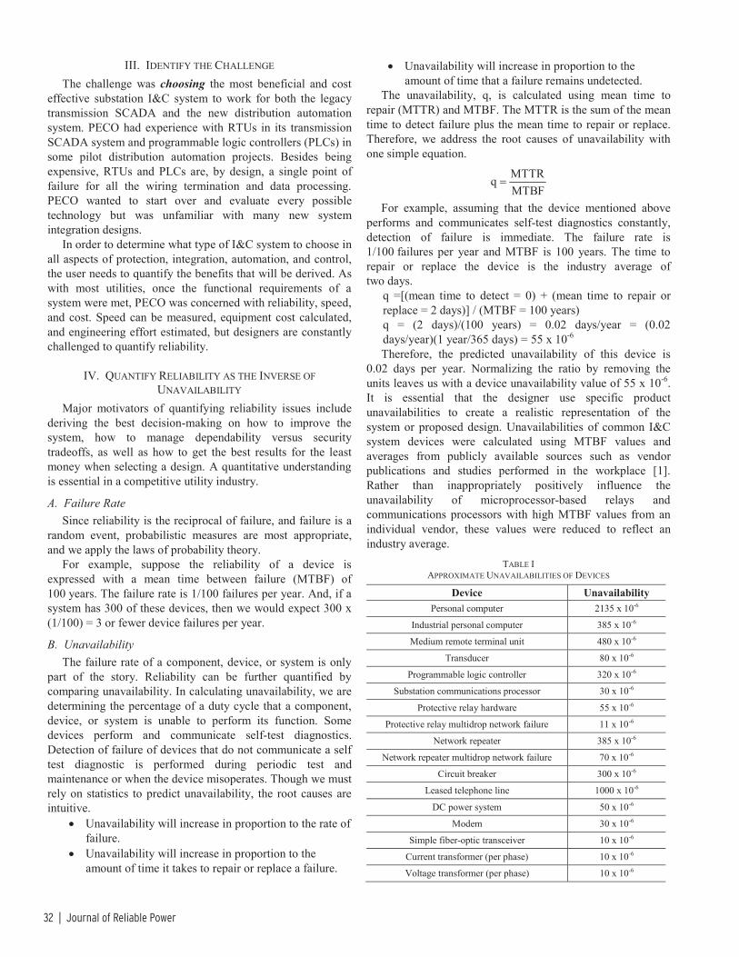
32 | Journal of Reliable Power
III. IDENTIFY THE CHALLENGE The challenge was choosing the most beneficial and cost
effective substation I&C system to work for both the legacy transmission SCADA and the new distribution automation system. PECO had experience with RTUs in its transmission SCADA system and programmable logic controllers (PLCs) in some pilot distribution automation projects. Besides being expensive, RTUs and PLCs are, by design, a single point of failure for all the wiring termination and data processing. PECO wanted to start over and evaluate every possible technology but was unfamiliar with many new system integration designs.
In order to determine what type of I&C system to choose in all aspects of protection, integration, automation, and control, the user needs to quantify the benefits that will be derived. As with most utilities, once the functional requirements of a system were met, PECO was concerned with reliability, speed, and cost. Speed can be measured, equipment cost calculated, and engineering effort estimated, but designers are constantly challenged to quantify reliability.
IV. QUANTIFY RELIABILITY AS THE INVERSE OF UNAVAILABILITY
Major motivators of quantifying reliability issues include deriving the best decision-making on how to improve the system, how to manage dependability versus security tradeoffs, as well as how to get the best results for the least money when selecting a design. A quantitative understanding is essential in a competitive utility industry.
A. Failure Rate Since reliability is the reciprocal of failure, and failure is a
random event, probabilistic measures are most appropriate, and we apply the laws of probability theory.
For example, suppose the reliability of a device is expressed with a mean time between failure (MTBF) of 100 years. The failure rate is 1/100 failures per year. And, if a system has 300 of these devices, then we would expect 300 x (1/100) = 3 or fewer device failures per year.
B. Unavailability The failure rate of a component, device, or system is only
part of the story. Reliability can be further quantified by comparing unavailability. In calculating unavailability, we are determining the percentage of a duty cycle that a component, device, or system is unable to perform its function. Some devices perform and communicate self-test diagnostics. Detection of failure of devices that do not communicate a self test diagnostic is performed during periodic test and maintenance or when the device misoperates. Though we must rely on statistics to predict unavailability, the root causes are intuitive.
• Unavailability will increase in proportion to the rate of failure.
• Unavailability will increase in proportion to the amount of time it takes to repair or replace a failure.
• Unavailability will increase in proportion to the amount of time that a failure remains undetected.
The unavailability, q, is calculated using mean time to repair (MTTR) and MTBF. The MTTR is the sum of the mean time to detect failure plus the mean time to repair or replace. Therefore, we address the root causes of unavailability with one simple equation.
MTTRqMTBF
=
For example, assuming that the device mentioned above performs and communicates self-test diagnostics constantly, detection of failure is immediate. The failure rate is 1/100 failures per year and MTBF is 100 years. The time to repair or replace the device is the industry average of two days.
q =[(mean time to detect = 0) + (mean time to repair or replace = 2 days)] / (MTBF = 100 years) q = (2 days)/(100 years) = 0.02 days/year = (0.02 days/year)(1 year/365 days) = 55 x 10-6 Therefore, the predicted unavailability of this device is
0.02 days per year. Normalizing the ratio by removing the units leaves us with a device unavailability value of 55 x 10-6. It is essential that the designer use specific product unavailabilities to create a realistic representation of the system or proposed design. Unavailabilities of common I&C system devices were calculated using MTBF values and averages from publicly available sources such as vendor publications and studies performed in the workplace [1]. Rather than inappropriately positively influence the unavailability of microprocessor-based relays and communications processors with high MTBF values from an individual vendor, these values were reduced to reflect an industry average.
TABLE I APPROXIMATE UNAVAILABILITIES OF DEVICES
Device Unavailability Personal computer 2135 x 10-6
Industrial personal computer 385 x 10-6
Medium remote terminal unit 480 x 10-6
Transducer 80 x 10-6
Programmable logic controller 320 x 10-6
Substation communications processor 30 x 10-6
Protective relay hardware 55 x 10-6
Protective relay multidrop network failure 11 x 10-6
Network repeater 385 x 10-6
Network repeater multidrop network failure 70 x 10-6
Circuit breaker 300 x 10-6
Leased telephone line 1000 x 10-6
DC power system 50 x 10-6
Modem 30 x 10-6
Simple fiber-optic transceiver 10 x 10-6
Current transformer (per phase) 10 x 10-6
Voltage transformer (per phase) 10 x 10-6

Case Study of a Large Transmission and Distribution Substation Automation Project | 33
We assume that mean time to detect failure is negligible since microprocessor-based relays, RTUs, and PLCs alert the system immediately if there is a failure in the system. Therefore, the MTTR is just the mean time to repair, which is assumed to be two days or .005 years.
Example: for a PC, unavailability is (MTTR = .005)/(MTBF = 2.56) = .002135.
Further, if the failure of interest can be caused by a PC or a microprocessor-based relay, it can be seen that a relay is (2135)/(55) = 39 times more reliable than a PC.
Reliability is inversely proportional to unavailability. The higher the unavailability value, the less available a device or system will be to perform its function and therefore cause failure.
V. IDENTIFY A SELECTION PROCESS
A. Fault Tree Method “Fault tree analysis,” a concept first proposed by H. A.
Watson of Bell Telephone Laboratories to analyze the Minuteman Launch Control System, can be used to combine device unavailabilities. This method, used and refined over the ensuing years [2], is attractive because it does not require extensive theoretical work and is a practical tool that any engineer can learn to use. While computer programs are available to assist in developing and analyzing complex fault trees, small fault trees, which are easily analyzed manually, are also useful.
If a system consists of several devices, use a fault tree to combine device unavailabilities to calculate the system reliability. Refer again to our device which has an unavailability of 0.02 days per year. The device might consist of two components, each with an unavailability of 0.01 days per year. Both components must operate properly for the device to be sound. The individual unavailabilities of the two components add up to the total unavailability of 0.02 days per year. Add the component unavailabilities to obtain the device unavailability if either component in a device can cause the device to fail.
Similarly, for a system with two devices which must operate properly for the system to be sound, add the device unavailabilities to obtain the system unavailability since either device could cause the system to fail.
On the other hand, our device with unavailability of 0.02 days per year might consist of two redundant components, each with an unavailability of 0.1414 days per year. Though the individual component unavailability is greater, in this example the components are redundant and either component can give satisfactory performance to the device. Therefore, the product of the individual component unavailabilities is the device unavailability. Multiply the component unavailabilities to obtain the device unavailability, if both components must fail to cause a device failure.
Similarly, for a system with two devices which operate redundantly, multiply the device unavailabilities to obtain the system unavailability since both devices must fail in order for the system to fail.
B. Fault Tree Construction A fault tree is tailored to a particular failure of interest and
models the part of the system which influences the probability of the failure. The failure of interest is called the top event. A given system may have more than one top event which merits investigation. As an example, consider the traditional RTU centric power and I&C system in Fig. 1 which consists of a circuit breaker, a leased line, a modem, three CTs and three VTs, a battery, an RTU, and eight associated transducers. What is the chance that the I&C system will fail to perform its function, i.e., acquire line data such as currents, voltages, kV, and kW, or fail to control the breaker. To answer this, consider the top event “No Line Data or Control.” The fault tree in Fig. 1 helps analyze this chance.
Use the fault tree to break the top event into lower-level events. The OR gates in Fig. 1 express the idea that any of several failures can cause the top event. The circuit breaker could fail OR the leased line could fail, OR the modem could fail, etc. For these simple fault trees, the lower-level events are basic events which are depicted with a circle and referred to as “roots.” The roots are failures of devices such as the leased line, modem, instrument transformers, or the dc subsystem.
It is important to identify all causes of the event of a system you are evaluating. This discipline helps find opportunities to improve overall reliability and helps calibrate the contribution of alternatives relative to other common failure causes. Use OR gates to combine multiple events, when any one failure will result in the failure of the event above the gate. Use AND gates to combine multiple events when all devices directly below the gate must fail in order to have a failure above the gate.
C. Fault Tree Analysis After entering event data, analysis of the fault tree shown
in Fig. 1 is straightforward using a single simplifying assumption known as the rare event approximation. It ignores the possibility that two or more rare events can occur simultaneously. For two events, each of which occurs with probability less than 0.1, the rare event approximation produces less than 5% error. When the events in question are failures, the rare event approximation is always conservative; the approximated probability of failure is always greater than the actual probability of failure [3].
Employing the rare event approximation, calculate the unavailability associated with each event expressed with an OR gate as the sum of the unavailability for each input to the OR gate. For example, the unavailability associated with the lower left OR Gate in Fig. 1 is the sum of the unavailability of the five inputs to that OR gate. The fault tree of Fig. 1 contains only basic events and OR gates. A failure could be caused by the circuit breaker, OR leased line, OR the modem, OR any of six instrument transformers, OR the battery, OR the RTU, OR any of eight associated transducers. Therefore the unavailability associated with the Top Event is simply the sum of all of the basic events or 2160 x 10-6.

34 | Journal of Reliable Power
The lower left OR gate identifies a fragment of the fault tree which would be common to all design choices. The lower right OR gate identifies the I&C fragment of the fault tree that is unique to each individual design. The examples use a leased line because PECO planned to use leased lines, as do most installed SCADA systems in the United States.
No Line 1 Data orControl
I&CEquipment
CommonSubstationEquipment
LeasedLine Fails
1000
ModemFails
30
CT/VTFails
60
1440
DCFails
50
BreakerFails300
TransducerFails240
720
RTUFails480
XDCRTU
2160
Fig. 1: Fault Tree for RTU-Based I&C System
D. Fault Tree for a Relay and Communications Processor Star I&C System
The fault tree in Fig. 2 includes a relay for the line and a communications processor to communicate with the master.
I&CEquipmentCommon
SubstationEquipment
LeasedLine Fails
1000
ModemFails
30
CT/VTFails
60
DCFails
50
BreakerFails300
CommunicationsProcessor
Fails30
MicroprocessorRelay Fails
55
No Line 1 Data orControl
1440 85
1525
Fig. 2: Fault Tree for Relay and Communications Processor Star I&C System
In this design, the communications processor acts as a substation grade client/server with a high MTBF, high availability, and great support for enhancement or expansion. The microprocessor-based relays connected in a star topology [4] collect data and refine it into information. It is also interesting to recognize that, in this design, as information is collected, it can be acted on at the appropriate level and passed no further than necessary. This reduces bandwidth requirements as you pass along only the information that is truly needed by a host.
Observe that for these examples the relay and communications processor star network I&C subsystem is 8.5 times more reliable than the RTU-based subsystem.
VI. EVALUATE THE SPECIFIC APPLICATION In 1997 PECO began a project to renovate the deteriorating
69 kV–13 kV Westmoreland substation, which presently supplies about one-third of Philadelphia’s electrical load. The project scope consisted of a complete turnkey transmission
and distribution automation solution from system design through installation and commissioning. The design involved a three-ended 230 kV transmission line to be tapped to supply three 90 MW transformers. Each transformer was to supply three 13 kV distribution buses which include feeders and capacitor banks, as well as tie lines to other stations. The existing four 69 kV subtransmission lines were to be connected in a ring bus arrangement.
The fault tree method tool can be used in mission-critical design applications, regardless of size. The previous simple examples have demonstrated the ease of construction and analysis for a nonredundant substation situation. Since the Westmoreland original requirements suggested 54 breakers and switches, the following example uses this method to compare redundant I&C designs with the top event “No line data or control of any of the 54 breakers and/or switches.” The example analyzes only the I&C fragment of the designs, the lower right fragment in the above examples, since the rest of the tree is common to each possible selection.
A. RTU Centric
Backup I&CFails
Primary I&CFails
No Line Data orControl of Any Oneof the 54 Breakers
15490 15490
240
RTUFails
(3)(480) =1440
TransducerFails
(54)(8)(30) =12960
ModemFails
30
LeasedLine Fails
1000
RTU XDC
RTUFails
(3)(480) =1440
TransducerFails
(54)(8)(30) =12960
ModemFails
30
LeasedLine Fails
1000
RTU XDC
I&CSubsystem
Fig. 3: Fault Tree for RTU Centric Westmoreland I&C System
In this RTU centric example, assume the use of a medium-sized RTU. Therefore, use the I/O capabilities and unavailability information for industry average medium-sized RTUs.
Each of the primary and backup I&C subsystems consists of 3 RTUs and 432 transducers. Since both primary AND backup must fail, the unavailability of each subsystem is ANDed together (or multiplied).
B. PLC Centric
Backup I&CFails
Primary I&CFails
No Line Data orControl of Any Oneof the 54 Breakers
16410 16410
269
PLCFails
(7)(320) =2240
TransducerFails
(54)(8)(30) =12960
ModemFails
30
LeasedLine Fails
1000
PLC XDC
PLCFails
(7)(320) =2240
TransducerFails
(54)(8)(30) =12960
ModemFails
30
LeasedLine Fails
1000
PLC XDC
I&CSubsystem
Fig. 4: Fault Tree for PLC Centric Westmoreland I&C System

Case Study of a Large Transmission and Distribution Substation Automation Project | 35
In this PLC example, assume the use of a medium-sized PLC. Therefore, use the I/O capabilities and unavailability information for industry average medium-sized PLCs.
Each of the primary and backup I&C subsystems consists of 7 PLCs, racks, and power supplies, as well as 432 transducers. Since both primary AND backup must fail, the unavailability of each subsystem is ANDed together (or multiplied).
C. Microprocessor-Based Relays I&C System PECO recognized that the innovative developments within
intelligent electronic devices (IEDs) in the substation created new ways of collecting and reacting to data and then using this data to create information. Simple communication methods between microprocessor-based relays, for example, enable data acquisition and control as well as superior protection systems. The same information created for protection can feed other system needs such as automation, monitoring, and control. By placing microprocessor-based protective relays near the equipment, wiring is reduced and data processing is distributed to be near the source. Control decisions can be made local to the equipment or come from a supervisory system. All data can be communicated via a single robust communication channel rather than the traditional method of a dedicated pair of copper conductors to sense every contact.
D. Multidrop Relay Network Centric Direct connect and multidrop are two types of data link
connections to protective relays. In a multidrop, Fig. 5, several devices can be physically connected in a bus network, and control of the transmit and receive conductors must be negotiated. A multidrop connection requires that only one relay communicate at a time. Software and hardware are used to determine which device has permission to transmit so that data does not collide on the conductor. Since several devices are connected, addressing is necessary within the protocol to identify the source and destination of the data being communicated. This addressing adds overhead in the form of processing time and amount of information that needs to be transmitted thus reducing the amount of data that can be transferred at a given speed. Devices compensate for this by increasing the speed at which they communicate and increasing the amount of communications processing they perform.
Multidrop Network
Hardware-SpecificProtocolInterface IED IED IED IED IED IED IED IED IED IED
Fig. 5: Multidrop Network IED Interface
It is important to keep in mind that if the mediation of control of data transmission should fail, none of the multidropped devices can communicate. This can be caused by relay communications hardware failing to release control, relay communications software failing to process mediation schemes correctly, or corruption of the network [5]. A
probable failure rate is that roughly one fifth of the failures of these devices do, in fact, affect the network.
Link toMaster Fails
IED SubsystemFails
No Line Data orControl of Any Oneof the 54 Breakers
13 1
3427
GatewayFails2133
GW
RepeaterFails
Network210
RPTR
Relay FailsNetwork
1070
ModemFails
30
LeasedLine Fails
1000
ModemFails
30
LeasedLine Fails
1000
Primary BackupPrimary Backup
I&CSubsystem
Micro-processorRelay Fails
2970
RepeaterFails385
RPTR
Micro-processorRelay Fails
2970
RepeaterFails385
RPTR
Fig. 6: Multidrop Relay Network Centric Westmoreland I&C System
Due to the nature of converting from one protocol language to another, this design includes a protocol gateway. The repeaters are necessary to connect the large quantity of relays onto a bus. This, in turn, changes the way you represent the redundancy of the system. The lower left AND gate represents the redundant IED I&C subsystems. The lower right AND gate represents the redundant host connections. Each relay, each repeater, and the protocol gateway has a failure mode that would cause the top event. The upper OR gate takes these failure modes into account with unavailabilities from the above table. Since the unavailability of the microprocessor-based relays in each of the primary and backup I&C subsystems is 2970 x 10-6, the total for all relays in the system is 5940 x 10-6, and the unavailability of the network, or chance that the bus will be disrupted, due to these components is roughly one fifth of the total or 1070 x 10-6. Three repeaters are needed with an unavailability total of 1155 x 10-6, and the unavailability of the network due to these components is roughly one fifth of this or 210 x 10-6. The gateway is a single point of failure for the entire network with an unavailability of 2133 x 10-6.
E. Communications Processor Star Relay Network Centric In a direct connection, there are only two devices
connected via a transmit and receive pair of conductors. Use each conductor to transmit from one device and receive by the other device. Since there are only two devices, each of them can constantly control the conductor on which they are transmitting and both can know implicitly to which other device they are connected. Direct connections to many relays allow each of them to communicate simultaneously. Many direct connections originating from one device is called a star network. Fig. 7 illustrates the star topology.
Relays
CommunicationsProcessor
Fig. 7: Star Topology

36 | Journal of Reliable Power
Many star networks can be connected in a parallel or vertical hierarchy. Any protocol can be used in this configuration. Virtually all microprocessor-based relays have a simple EIA-232 serial port connection to support direct connections. Any of the other communication methods can be used in a direct connection as well.
Direct connection designs allow the network to support a wide range of relay capabilities. Simple, slow communicating devices can coexist with more complex fast communicating relays.
Open architecture is a term that refers to networks that are interoperable among vendors. The star network is the only design that is truly open and accommodates multiple protocols, multiple baud rates, and multiple network interfaces.
It is important to keep in mind that if the mediation of control of data transmission of a device in a star configuration should fail, none of the other directly connected relays are affected. Using the relay’s redundant counterpart, the system continues to function in the absence of the failed relay.
Backup I&CFails
Primary I&CFails
No Line Data orControl of Any Oneof the 54 Breakers
4150 2665
11
Micro-processorRelay Fails
2970
CommunicationsProcessor
Fails150
ModemFails30
LeasedLine Fails
1000
CommunicationsProcessor
Fails150
ModemFails
30
LeasedLine Fails
1000
Micro-processorRelay Fails
1485
I&C Subsystem
Fig. 8: Communications Processor Star Relay Network Centric Westmoreland I&C System
Backup protection for distribution is done with dual application relays; thus, the system is made even simpler with fewer devices. The unavailability of the 54 microprocessor-based relays in the primary I&C subsystems is 2970 x 10-6. The unavailability of the 27 microprocessor-based relays in the backup I&C subsystems is 1485 x10-6. The unavailability of five communications processors totals 150 x 10-6.
Table II summarizes the I&C subsystem unavailability for the four architectures, and for interest, compares both redundant and nonredundant designs.
TABLE II I&C SUBSYSTEM UNAVAILABILITY FOR 54 BREAKER/SWITCH DESIGN
Nonredundant Design
Redundant Design
RTU Centric 15490 x 10-6 240 x 10-6
PLC Centric 16410 x 10-6 269 x 10-6
Multidropped Relay Network Centric 7158 x 10-6 3427 x 10-6
Communications Processor Star Relay Network Centric 4150 x 10-6 11 x 10-6
From Table II it can be seen that in addition to the obvious benefit of providing protection, the redundant communications processor centric system design is 22 times more reliable than a redundant RTU design and 25 times more reliable than a redundant PLC design. It can further be seen that the redundant communications processor star relay network centric system design is 312 times more reliable than the redundant multidrop microprocessor relay design.
Why is the communications processor star relay network centric design so much more reliable? This protection subsystem is elegant by its simplicity. The streamlined architecture performs all the necessary functions with a minimal number of components. Thus, the system design is more reliable. The modular nature of the architecture allows for future expansion as well.
The reliability of these substation grade components as well as the use of fiber optics further adds to the reliability of this system design. These components all meet IEEE SWC and radiated EMI tests as well as IEC impulse voltage, vibration, shock, and bump tests—to name a few. The protection vendor that was eventually chosen employed an innovative arc interruption technology in the relays which eliminates contact wear and auxiliary relays as well as speeds tripping time. Relays are often mounted on doors, in swing panels or directly in equipment that subject them to vibration. Also, during shipment they might be dropped or otherwise abused. Recognizing this long ago, the protection vendor incorporated vibration testing as part of its design. The wide operational temperature range of the protective relays also adds to their reliability. In addition to the ability to use the relays in extremely harsh environmental conditions such as the pole-top, they will suffer degradation, due to temperature, at a much slower rate than products designed to meet lower standards.
An interesting benefit to this analysis was that there existed two direct correlations between reliability and cost. The obvious one is that redundant systems of a particular design are more reliable and more costly than nonredundant systems of the same design. However, when comparing different designs, the most reliable design has fewer devices and components. Fewer components translate into fewer costs. Therefore, for this and many other examples, as you drive reliability up, you drive cost down.
Table III summarizes the I&C subsystem capital equipment costs for the hardware necessary to perform data acquisition and control for the four different architectures. Both redundant and nonredundant designs are compared. As with the MTBF values, the cost numbers are derived from industry averages. We encourage individuals to use their known costs to create specific comparisons.

Case Study of a Large Transmission and Distribution Substation Automation Project | 37
TABLE III I&C SUBSYSTEM HARDWARE COSTS FOR 54 BREAKER/SWITCH DESIGN
Nonredundant Design
Redundant Design
RTU Centric $189,700 $379,400
PLC Centric $210,700 $421,400
Multidropped Relay Network Centric $60,400 $116,100
Communications Processor Star Relay Network Centric $12,500 $25,000
Since protection is necessary for each design, the examples assume protection costs to be the same for any of the designs and leave this cost out of these comparisons. The RTU and PLC example costs for integration include all of the RTU, PLC, and transducer hardware. Protection components are a separate investment. The multidrop and communications processor centric relay solutions involve costs for network interfaces, communications equipment, and communications processors. Transducers are not necessary. The distributed nature of the microprocessor-based relay design also reduces wiring, documentation, etc., and all of the associated costs.
F. RTU Centric The nonredundant network requires three RTUs ($10,500),
multiple I/O panels ($28,000), 324 volt and amp transducers ($97,200), 108 kvar and kW transducers ($54,000) = $189,700. Cost of a redundant system is twice this design cost.
G. PLC Centric The nonredundant network requires seven PLCs ($22,750),
seven racks ($5,250), seven power supplies ($3,500), multiple I/O panels ($28,000), 324 volt and amp transducers ($97,200), 108 kvar and kW transducers ($54,000) = $210,700. Cost of a redundant system is twice this design cost.
H. Multidrop Relay Network Centric The nonredundant network requires 54 relay network
protocol interfaces ($54,000), two repeaters ($3,400), one gateway ($3,000) = $60,400. Redundant design involves 54 additional relay network protocol interfaces ($54,000) and one additional repeater ($1,700) = $116,100.
I. Communications Processor Star Relay Network Centric The communications processor centric design for this
original Westmoreland comparison requires five communi-cations processors ($12,500) for a total = $12,500. The redundant design involves five additional communications processors ($12,500) for a total = $25,000.
VII. CHOOSE THE COMMUNICATIONS PROCESSOR STAR RELAY NETWORK
One last consideration was that though the microprocessor-based relay and communications processor vendor was well established, in fact PECO engineers had already successfully installed more than 100 of the vendor’s relays, they were cautious about trying something new. They were reassured to learn that the vendor had several hundred customers around
the globe for each of the devices that PECO was considering in the design. This design was simply a new innovative twist on well-established protective relay technology, simply reusing already available data and control.
After fully evaluating the solutions available, PECO engineers chose the communications processor star relay network centric design. In so doing they were able to upgrade their transmission I&C system, install a distribution I&C system, and completely replace all of their protection systems … all for less cost than a traditional SCADA I&C system. In essence, they felt that they had successfully chosen the most reliable SCADA solution that incidentally offered a premier protection replacement at no additional cost. They enhanced their system requirements to address protection as follows.
No single point of failure would result in loss of data acquisition, control or protection of any piece of substation equipment.
A completely integrated microprocessor-based protective relay design was envisioned which would further minimize maintenance cost through the use of self-checking and relay setting verification. Communications processors would collect and organize the data from the protective relays and some micro PLCs local to the transformers and breakers. Significant benefits of the system would include remote access to the substations from PECO’s central office complex, allowing remote configuration and control of relays, and complete SCADA visibility through a substation integration system. In addition to the local displays and control buttons on the relays, an off-the-shelf human machine interface (HMI) software package was to be used to create a customized interface for PECO for local substation control. The interface would need to view settings, change settings, and download relay data. The protection and control network of relays and communications processors was to be designed to provide the SCADA interface so the local computer serves only as an interface to view all of the information and provide access to all of the controls in the substation. Should the PC fail, remote control would be unaffected.
Ultimately, PECO elected to use this topology to implement a major protection and automation upgrade at 87 existing substations.
Although the communications processor star relay network centric design accommodates using in-service IEDs and IEDs from multiple vendors, for the rebuild PECO elected to replace all of the protection components with new products, and they elected to use a single vendor for both primary and backup protection. PECO felt that the product reliability of the protection vendor they chose was so high that they could not increase reliability by choosing separate vendors for primary and backup. However, different products from the vendor were used as primary and backup.
The chosen design offered full redundancy of primary and backup protection as well as communications. The failure of any one of the protection or communication components will not prevent monitoring or control of any one of the 54 breakers and/or switches in the substation.

38 | Journal of Reliable Power
“This design reflects a substation integration system that has gone well beyond our previous separate systems for protection, data acquisition, and control. The new design uses [Protection Vendor] equipment on an unprecedented scale and is the largest single integrated system for protection, control, data acquisition, and monitoring ever undertaken by PECO,” says Jack Leonard, PECO Supervising Engineer, System Monitoring, and Control.
A. Other Communications Processor Star Relay Network Advantages
• IED integration enhances distribution automation, SCADA, and protection by migrating some of the communications functions to an intermediate substation device. Moving protocols into the IEDs adds to their cost and accelerates their obsolescence as technology advances. The resources available within the IEDs are instead better focused on optimizing protection solutions.
• System automation, control, and supervisory data available in protective relays enhance protection and control of individual power system components as well as the entire power system by permitting rapid, well-informed decisions. Adaptive protection and control methods are used as the power system configuration changes dynamically.
• Device diagnostic data enhance distribution automation, SCADA, and protection by maximizing the availability of the protection system.
• Historical data available in protective relays enhance distribution automation, SCADA, and protection through dynamic system trend analysis as well as being the source for remote operator and process forensic analysis. By continually monitoring conditions of devices over time, operators and processes develop a clearer picture of device performance.
• The communications processor can act as a client/server, data concentrator, substation archive, programmable logic platform, gateway, router, dial-out device, communication switch, and time synchronization broadcaster.
• The communications processor can communicate without developing vendor-specific protocol software and can eavesdrop on conversations between two devices in the I&C system.
• Star networks can acquire and transfer substation integration data using much slower direct connections. These direct connections are also more reliable, more robust, and less expensive.
• The communications processor simplifies implementation through autoconfiguration. This is similar, though not as comprehensive, as current efforts by the utility communication architecture (UCA) movement to define this function.
• Direct connection designs allow the network to support a wide range of IED capabilities. Simple, slow
communicating devices can coexist with more complex fast communicating relays.
• Communications processors enhance the value of the distribution automation, SCADA, and protection I&C system data by making it available to multiple master systems and other users.
• As protocol requirements change in the substation, an individual communications processor can be upgraded instead of each of the IEDs. Protection, monitoring, and control are left undisturbed and in service as a protocol change is made. It is also more economical to make this change in a single device.
• The age of IEDs that are in substations today varies widely. Many of these IEDs are still useful but lack the most recent protocols. Rarely is a substation integration upgrade project undertaken where all existing IEDs are discarded. A communications processor that can communicate with each IED via a unique baud rate and protocol can extend the usefulness of IEDs. Using a communications processor for substation integration also easily accommodates future IEDs.
• Networks are made up of direct and multidrop connections. Point-to-point star networks are much more reliable than multidrop networks. It is important to keep in mind that if the mediation of control of data transmission should fail, none of the multidropped devices can communicate.
• Troubleshooting communications problems is much faster and more efficient through simple LED indication on direct links from a communications processor than attempting to decipher multidrop networks.
• Protocol standardization does not mean that every IED must use the same protocol; it means that each protocol must be explicitly defined to support interoperability.
VIII. IMPLEMENT A SYSTEM PECO’s new substation uses a completely integrated
protection and control design, comprised of over 140 microprocessor-based relays and communications—making the substation perhaps the largest completely microprocessor-controlled substation in existence. The design exploits many of the advanced programming and communication capabilities of microprocessor-based relays. All of the relays are integrated into an SI system to provide SCADA visibility and to provide information and control capabilities to a local HMI. The system increases the efficiency of substation maintenance through the use of automated reporting of all pertinent relay-generated fault data and breaker trouble conditions. The economical design allows primary and backup redundant fault clearing for all single contingency fault conditions while intuitively replicating, and to some degree enhancing, existing electromechanical protection philosophies. The relay digital communications capabilities also allow fast and reliable supervisory control
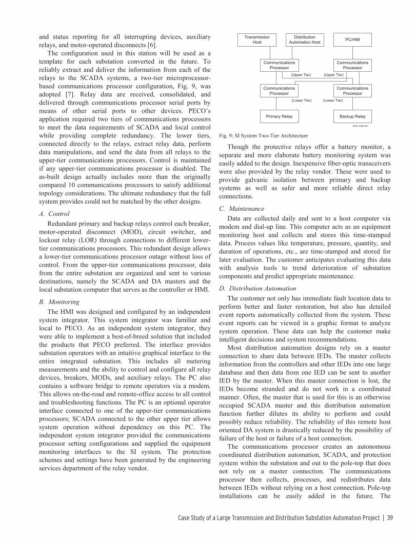
Case Study of a Large Transmission and Distribution Substation Automation Project | 39
and status reporting for all interrupting devices, auxiliary relays, and motor-operated disconnects [6].
The configuration used in this station will be used as a template for each substation converted in the future. To reliably extract and deliver the information from each of the relays to the SCADA systems, a two-tier microprocessor-based communications processor configuration, Fig. 9, was adopted [7]. Relay data are received, consolidated, and delivered through communications processor serial ports by means of other serial ports to other devices. PECO’s application required two tiers of communications processors to meet the data requirements of SCADA and local control while providing complete redundancy. The lower tiers, connected directly to the relays, extract relay data, perform data manipulations, and send the data from all relays to the upper-tier communications processors. Control is maintained if any upper-tier communications processor is disabled. The as-built design actually includes more than the originally compared 10 communications processors to satisfy additional topology considerations. The ultimate redundancy that the full system provides could not be matched by the other designs.
A. Control Redundant primary and backup relays control each breaker,
motor-operated disconnect (MOD), circuit switcher, and lockout relay (LOR) through connections to different lower-tier communications processors. This redundant design allows a lower-tier communications processor outage without loss of control. From the upper-tier communications processor, data from the entire substation are organized and sent to various destinations, namely the SCADA and DA masters and the local substation computer that serves as the controller or HMI.
B. Monitoring The HMI was designed and configured by an independent
system integrator. This system integrator was familiar and local to PECO. As an independent system integrator, they were able to implement a best-of-breed solution that included the products that PECO preferred. The interface provides substation operators with an intuitive graphical interface to the entire integrated substation. This includes all metering measurements and the ability to control and configure all relay devices, breakers, MODs, and auxiliary relays. The PC also contains a software bridge to remote operators via a modem. This allows on-the-road and remote-office access to all control and troubleshooting functions. The PC is an optional operator interface connected to one of the upper-tier communications processors; SCADA connected to the other upper tier allows system operation without dependency on this PC. The independent system integrator provided the communications processor setting configurations and supplied the equipment monitoring interfaces to the SI system. The protection schemes and settings have been generated by the engineering services department of the relay vendor.
CommunicationsProcessor
PC/HMI
CommunicationsProcessor
CommunicationsProcessor
TransmissionHost
CommunicationsProcessor
(Upper Tier) (Upper Tier)
(Lower Tier) (Lower Tier)
DistributionAutomation Host
Backup RelayPrimary Relay
DWG. 6084-002
Fig. 9: SI System Two-Tier Architecture
Though the protective relays offer a battery monitor, a separate and more elaborate battery monitoring system was easily added to the design. Inexpensive fiber-optic transceivers were also provided by the relay vendor. These were used to provide galvanic isolation between primary and backup systems as well as safer and more reliable direct relay connections.
C. Maintenance Data are collected daily and sent to a host computer via
modem and dial-up line. This computer acts as an equipment monitoring host and collects and stores this time-stamped data. Process values like temperature, pressure, quantity, and duration of operations, etc., are time-stamped and stored for later evaluation. The customer anticipates evaluating this data with analysis tools to trend deterioration of substation components and predict appropriate maintenance.
D. Distribution Automation The customer not only has immediate fault location data to
perform better and faster restoration, but also has detailed event reports automatically collected from the system. These event reports can be viewed in a graphic format to analyze system operation. These data can help the customer make intelligent decisions and system recommendations.
Most distribution automation designs rely on a master connection to share data between IEDs. The master collects information from the controllers and other IEDs into one large database and then data from one IED can be sent to another IED by the master. When this master connection is lost, the IEDs become stranded and do not work in a coordinated manner. Often, the master that is used for this is an otherwise occupied SCADA master and this distribution automation function further dilutes its ability to perform and could possibly reduce reliability. The reliability of this remote host oriented DA system is drastically reduced by the possibility of failure of the host or failure of a host connection.
The communications processor creates an autonomous coordinated distribution automation, SCADA, and protection system within the substation and out to the pole-top that does not rely on a master connection. The communications processor then collects, processes, and redistributes data between IEDs without relying on a host connection. Pole-top installations can be easily added in the future. The

40 | Journal of Reliable Power
communications processor also provides data acquisition and control to the remote or local hosts but continues with DA functions should the hosts fail. Also, direct links can be established between microprocessor-based relays and recloser controllers based on these relays, as an example, so that protection and automation data can be directly, quickly, and reliably transferred peer-to-peer. Further, the communications processor can support mediation of local or remote control of the entire system.
E. Equipment Monitoring Trip coil monitoring is an example of verifying auxiliary
equipment. Control Equations in the relays can be used to perform trip coil monitoring as well as other functions in the system, such as capacitor bank supervision and sophisticated reclose and tripping requirements. Personnel safety is enhanced through the fast trip scheme for hot-line maintenance, which provides flashover detection. Simple topology and communication LEDs offer easier and faster communications troubleshooting.
F. Protection The microprocessor-based relay and communications
processor I&C system also performs the following protection and control [6].
13 kV feeder protection and control 13 kV tie line protection and control 13 kV capacitor bank protection and control 13 kV bus protection and control 13 kV bus tie protection 230/13 kV transformer protection 230 kV circuit switcher remote control 230 kV line protection and control 230 kV bus protection and control
As of this writing, five substations, including Westmoreland, have been successfully integrated on the PECO system. Three more are planned for 1998.
IX. REALIZE MANY KEY ADVANTAGES TO PECO
A. Distributed Topology • Number of relays reduced by 75% • Analog wiring reduced by 30% • Control wiring reduced by 50% • Failures detected within seconds vs. at next
maintenance interval • Breaker isolation and system restoration reduced from
hours to minutes
B. Enhanced System Topology • Automatic fault data • Remote access to detailed event reports • View oscillography and digitals for timing details and
operation analysis • Make system improvement recommendations based
on data • Verify auxiliary equipment (trip coil)
• Automated system operation supervision for breaker closing
• Reduced maintenance • Increased personnel safety • “Fast Trip” scheme provides instantaneous tripping
during hot-line maintenance • Flashover detection for open switches
X. RECOGNIZE ADDITIONAL SYSTEM BENEFITS
A. Choose Products From Any Vendor The substation grade, communications processor star relay
network centric design does not require the high-speed networks within the substation but can easily connect to them. The solution is nonvendor-specific. Previously installed or newly procured devices from any manufacturer may be connected to the system and eavesdropping can be used to retrieve data via a nonintrusive data link from islanded systems that have no additional communication capabilities.
B. Leave Protection, Monitoring, and Control Undisturbed While Changing Protocols
One of the most important design features may be the fact that the network protocols are deployed in the upper-tier communications processors. If need arises to add or change a new network protocol or connection, this is easily accomplished in the communications processor. Data acquisition, control, and protection continue uninterrupted within the protection system as network protocol needs change.
C. Integrate Devices Inside and Outside the Substation You can easily incorporate devices outside the substation
into your design, such as distribution automation controllers out on a pole-top application. This allows coordination between protection, automation, and control products for intelligent sectionalization and restoration. This produces fewer outages, shorter duration of outages, and thus, fewer affected customers. The trial and error method of detecting faults is replaced by fault location.
D. Enhance Power Quality Power quality is a broad concept used in comparing the
actual power system values to their ideal. Although there are many dedicated power quality measurement devices, relays are an effective measurement and storage device for some power quality data. Harmonics, frequency, voltage sag, voltage swell, and voltage interrupt are examples of power quality data captured by relays.
The relay vendor created a power quality feature called voltage sag swell interrupt (VSSI). An additional set of triggers capture power quality event data such as wave form deformation and/or sagging and/or swelling. The power quality event report is similar to a fault event report, but is of longer duration, to be sure to capture enough information, to effectively analyze a VSSI event.
Most significant power quality problems are identifiable as power system voltage variations: complete interruption of

Case Study of a Large Transmission and Distribution Substation Automation Project | 41
voltage (<0.1 per unit), undervoltage (sag), and overvoltage (swell). A large percentage of these voltage variations are a result of power system faults. Recording and reporting voltage variation in the relay allows low cost correlation and validation of power consumer complaints. Monitoring the power quality allows the relay to react and compensate for power system variation or to alert users.
E. Benefit From Revenue Class Metering Accuracy Except for transformers with very few windings, revenue
and protection CTs act the same. The difference is that revenue class CTs go into saturation so as to protect the revenue meter to which they are usually attached. Electromechanical relays have such a large burden that, in the past, it was not possible to get revenue class accuracy from the protection CT with electromechanical relays attached. The burden of microprocessor-based relays is so small that we can get revenue class accuracy on a protection CT. In fact, PECO’s relay vendor has metering accuracy that equals or exceeds the accuracy of revenue meters between 0.8 and 1.0 power factor. These data can be easily used to verify calibration of revenue devices. The relays obviously also continue to read current values in a fault condition whereas the revenue meters must be protected by a saturating CT.
XI. CONCLUSION The challenge is often choosing the most beneficial and
cost effective substation design. Major motivators of quantifying reliability issues include
deriving the best solutions on how to improve the system, how to manage dependability versus security tradeoffs, as well as how to get the best results for the least money when selecting a design. A quantitative understanding is essential in a competitive utility industry. As with most utilities, once the functional requirements of a system were met, PECO was ultimately concerned with reliability, speed, and cost. Speed can be measured, equipment cost calculated, and engineering effort estimated but designers are constantly challenged to quantify reliability.
The failure rate of a component, device or system is only part of the story. Reliability can be further quantified by comparing unavailability. In calculating unavailability, we are determining the percentage of a duty cycle that a component, device, or system is unable to perform its function.
Though we must rely on statistics to predict unavailability, the intuitive root causes are that unavailability will increase proportionally to the rate of failure, unavailability will increase proportionally to the amount of time it takes to repair or replace a failure and unavailability will increase proportionally to the amount of time that a failure remains undetected.
“Fault tree analysis,” a concept first proposed by H. A. Watson of Bell Telephone Laboratories, can be used to combine device unavailabilities. This method, used and refined over the ensuing years, is attractive because it does not require extensive theoretical work and is a practical tool that any engineer can learn to use. The author has shown that small
fault trees, which are easily analyzed manually, are also very useful. The fault tree method tool can be used in mission-critical design applications, regardless of size.
The communications processor star relay network centric design subsystem is elegant in its simplicity. The streamlined architecture performs all the necessary functions with a minimal number of components. Thus, the system design is more reliable. The modular nature of the architecture allows for future expansion as well.
An interesting benefit to performing this analysis was that two direct correlations between reliability and cost were found. The obvious one is that redundant systems of a particular design are more reliable and more costly than nonredundant systems of the same design. However, when comparing different designs, the most reliable design has fewer devices and components. Fewer components translate into fewer costs. Therefore, for this and many other examples, as you drive reliability up, you drive cost down.
The customer not only has immediate fault location data to perform better and faster restoration, but also detailed event reports automatically collected from the system. These event reports can be viewed in a graphic format to analyze system operations. These data can help the customer make intelligent decisions and system recommendations.
IED integration enhances distribution automation, SCADA, and protection by migrating some of the communications functions to an intermediate substation device. Moving protocols into the IEDs adds to their cost and accelerates their obsolescence as technology advances. The resources available within the IEDs are instead better focused on optimizing protection solutions.
System automation, control, and supervisory data available in protective relays enhance protection and control of individual power system components as well as the entire power system by permitting rapid, well-informed decisions. Adaptive protection and control methods are used as the power system configuration changes dynamically.
Device diagnostic data enhance distribution automation, SCADA, and protection by maximizing the availability of the protection system.
Star networks can acquire and transfer the distribution automation, SCADA, and protection data using much slower direct connections. These direct connections are also more reliable, more robust, and less expensive.
The star network is the only design that is truly open and accommodates multiple protocols, multiple baud rates, and multiple network interfaces.
Communications processors enhance the value of the distribution automation, SCADA, and protection I&C system data by making it available to multiple master systems and other users.
Substation integration designs that rely on a master connection cannot share data between IEDs when this connection is lost. The IEDs become stranded and do not work in a coordinated manner. The communications processor creates an autonomous coordinated distribution automation, SCADA, and protection system within the substation that does
42 | Journal of Reliable Power
not rely on a master connection and allows mediation of local or remote control of the entire substation.
The age of IEDs that are in substations today varies widely. Many of these IEDs are still useful but lack the most recent protocols. Rarely is a substation integration upgrade project undertaken where all existing IEDs are discarded. A communications processor that can communicate with each IED via a unique baud rate and protocol can extend the usefulness of IEDs. Using a communications processor for substation integration also easily accommodates future IEDs.
Networks are made up of direct and multidrop connections. Point-to-point star networks are much more reliable than multidrop networks. It is important to keep in mind that if the mediation of control of data transmission should fail, none of the multidropped devices can communicate.
The rebuilt Westmoreland substation exploits virtually all of the capabilities of microprocessor-based relays. The new substation contains more than one hundred microprocessor-based relays, integrated into an SI system comprised of 22 communications processors. This is perhaps the largest substation of its kind ever built.
Increased visibility of system trouble and relay alarms is obtained by incorporating relay targets and event reports into the SI system so operators and engineers can diagnose and maintain the system.
The economical design uses relays to control breakers and other devices, and report on the status of each breaker. Metering data on all equipment is derived from the relays, displayed on the local HMI controller, and sent to the remote SCADA operators. These features eliminate substation RTUs, transducers, meters, and control switches.
Transmission breaker failure relaying is enhanced through the use of sophisticated logic that controls the breaker, lockout auxiliaries, and MODs, isolating the failed breaker. This logic enables safe operator control of the breakers, switches, and MODs for quick load restoration.
The microprocessor features allow sophisticated testing techniques to quickly and efficiently test many relay elements in repeatable programmed tests. The results of these tests are stored in software for later reference. Load checking is easily performed from a remote location without additional test equipment. Relay setting verification is achieved during relay configuration through database software, reducing relay setting time by half and increasing accuracy.
XII. BIOGRAPHY David J. Dolezilek received his BSEE from Montana State University in 1987. In addition to independent control system project consulting, he worked for the State of California, Department of Water Resources, and the Montana Power Company before joining Schweitzer Engineering Laboratories, Inc. in 1996 as a system integration project engineer. In 1997 Dave became the Director of Sales for the United States and Canada and he now serves as the Engineering Manager of Research and Development in SEL’s Automation and Communications Engineering group. He continues to research and write technical papers about innovative design and implementation affecting our industry, as well as participate in working groups and technical committees. He is a member of the IEEE and the International Electrotechnical Commission (IEC) Technical Committee 57.
XIII. REFERENCES [1] Gary W. Scheer, “Answering Substation Automation Questions Through
Fault Tree Analysis.” Proceedings of the Fourth Annual Substation Automation Conference, Texas A&M University, College Station, Texas, April 8 - 9, 1998.
[2] Hiromitsu Kumamoto and Ernest J. Henley, “Probabilistic Risk Assessment and Management for Engineers and Scientists.” 2nd Ed. IEEE Press, Pascataway, NJ, 1996.
[3] P. M. Anderson, B. Fleming, T. J. Lee, E. O. Schweitzer III, “Reliability Analysis of Transmission Protection Using Fault Tree Methods.” Proceedings of the 24th Annual Western Protective Relay Conference, Spokane, Washington, October 21 - 23, 1997.
[4] E. O. Schweitzer III, Gary W. Scheer, and David Dolezilek, “Comparison of SEL-2020 Star Network to Shared Networks.” Schweitzer Engineering Laboratories, Inc., 1997.
[5] Dave Dolezilek and Dean Klas, “Using Information From Relays to Improve the Power System.” Schweitzer Engineering Laboratories, Inc., 1998.
[6] James A. Schwenk, Mark D. Diehl, and Robert A. Crognale, “Microprocessor Relay Capabilities Improve Protection, SCADA, and Maintenance.” Proceedings of the 25th Annual Western Protective Relay Conference, Spokane, Washington, October 13 - 15, 1998.
[7] David Wood, “Two-Tiered Redundant SEL 2020 Control and Data Acquisition Example (A “Job Done” Example).” Application Guide 98-04, Schweitzer Engineering Laboratories, Inc., 1998.
Copyright © SEL 1998, 1999 All rights reserved.
990823 • TP6084-01

Proven Drop-In Control House Turnkey Solution for Total Protection, Monitoring, Automation, and Control of T&D Substations: A Case Study in Justification and Implementation
| 43
Proven Drop-In Control House Turnkey Solution for Total Protection, Monitoring,
Automation, and Control of T&D Substations A Case Study in Justification
and Implementation Brian McDermott, Duke Power
David Dolezilek and Timothy P. Tibbals, Schweitzer Engineering Laboratories, Inc.
Abstract—New protection, monitoring and control installations have evolved into complete turnkey control house installations. The entire control house, or just the panels, are pre-engineered, designed, pre-constructed, and pre-tested off-site and then installed in the substation. This new solution is less expensive and more reliable due to enhanced functionality of today’s microprocessor-based relays and communications processors.
The Belmont Tie Substation is not the first substation upgraded as part of Duke Power’s Substation Automation and Relay Upgrade program. However, it is the first to be built as a complete control house off-site and then delivered intact and “dropped in” to the substation yard. Once positioned in the yard, field wiring is terminated and the station is commissioned.
Although the “drop-in control house” design and implementation strategy is innovative in its own right, the true advancements were the integration of the substation control, monitoring, and data acquisition functionality into the protective relay and communications processors. The following is a list of achievements:
1. Control and monitoring functions are performed by the microprocessor relays installed at the substation. The microprocessor relays are responsible for tripping and closing the breakers either via automation settings, or via local or remote operator contacts. The relays send back the status of the breakers along with the operational and maintenance data for the substation apparatus.
2. Communications processors perform the data concentration and remote terminal functionality. These communications processors are the link between the relays and the substation computer. They also provide the link through a digital lease line to Duke Power’s Transmission Control Center (TCC). The TCC is responsible for the monitoring and operations of Duke Power’s transmission system.
3. Capacitor control is performed by the microprocessor relay protecting the capacitor. This relay is programmed to perform the switching of the capacitor banks as needed for correct operation.
4. Analog data from the electrical lines is measured by the microprocessor relays. This includes the Thermal Demand readings, Energy readings, Voltage readings, Current readings, and Instantaneous Megawatt and Megavar readings.
5. Breaker Condition Monitoring is performed by the microprocessor relays. This includes the breaker operational counters, the integrated peak and average fault current readings, and the percent contact wear.
6. Sequential Events Recorder (SER), or sequence-of-events (SOE) is performed by the microprocessor relays. At one station over 1100 SOE points are assigned in the relays. The SOE data reports automatically to the station computer and Duke Power’s database server where they are stored, sorted, and displayed. A web-based browser is used to display the SOE log remotely.
7. Analog fault recordings are performed automatically through the microprocessor relays. Whenever a fault occurs and the relay operates the breaker, an analog fault record is recorded.
8. Fault location and magnitude is calculated by the relay, this information is mapped back to the station computer for display on the Human-Machine Interface (HMI) and made available to the TCC.
9. The microprocessor relay collects substation alarms. These alarm points are mapped back to the station computer for display on the HMI, stored, and transferred to Duke Power’s, Electric Transmission (ET) PI database server. A web-based browser is used to display the alarm log remotely.
10. All equipment tagging (Red, Yellow, Orange, and Blue) is displayed on the microprocessor relay’s LCD display and the substation computer. A history of the tags is maintained through a database file.
11. All backup control, monitoring, and data displaying is performed by the microprocessor relay. The control and monitoring of the station does not rely on the station computer; complete control and monitoring remain available through the communications processors and the microprocessor relays.
12. Quantity of installed electrical panels was reduced by a factor of two.
13. RTD inputs providing top oil, ambient, and winding temperatures are collected from a transformer monitor IED. The communication system digitally collects this temperature information, along with fan current and status points such as low liquid, sudden pressure, and slow gas. Decisions are also made to control the cooling system and report alarm indications.

44 | Journal of Reliable Power
14. Rather than simply monitoring the battery voltage level, the system digitally communicates with the battery charger, which provides metering functions for the battery charge current, battery voltage, service voltage, and battery temperature. The charger also provides alarm conditions for low battery voltage, high charge rate, high battery voltage, battery symmetry, positive ground, negative ground, and component failure.
The Belmont Tie Substation is one of several substations being upgraded as part of this ongoing project. This paper was created as a case study of a total substation control house design and installation.
I. INTRODUCTION In the spring of 1998, Duke Power, Electric Transmission
(ET) began developing an automation strategy for transmission substations. Historically, ET had utilized separate equipment for Supervisory Control and Data Acquisition (SCADA) and protective relaying functions in the substation. This legacy equipment consisted of electro-mechanical relays and telemetry SCADA systems; combining protection and SCADA functionality was not possible. Beneficial functionality, such as sequence-of-events (SOE), digital fault recording (DFR), breaker condition monitoring (BCM), and annunciation would require installation of separate equipment. Since additional equipment from multiple vendors does not typically utilize a common communication pathway, this would have resulted in higher installation and maintenance costs as well as low reliability.
ET’s ability to retrieve operating information to assist in maintenance and engineering analysis is greatly hampered by this system architecture. Furthermore, most of the SCADA and protective relaying equipment is approaching an age where end-of-life issues must be considered. The Transmission Substation Automation & Relay Team (TSAR-Team) was formed to develop and implement an automation strategy to address these obsolete terminals.
Albemarle Switching Station was the first Duke Power Substation designed using the microprocessor relay to fully integrate all protection, control, and monitoring functions required from an electrical terminal perspective. This station proved successful and formed the basis for ET’s automation/integration strategy.
A. Lessons Learned Albemarle Switching Station created many new design
standards, and as such, significant learning took place on the pilot project. The following is a summary of some of the “Lessons Learned.”
1) Partnerships Offset Learning Costs The learning curve for implementing substation automation
is a steep one. Significant in-house training must be performed. Industry standards are not available to aid in the design process. The unavailability of standards is further complicated by the lack of integration tools to perform the necessary work. Methods for mitigating these costs include partnering with a systems integrator and sharing lessons learned with other utilities.
2) Standards Reduce Cost The automation of Albemarle Switching Station paved the
way for Duke Power’s transmission upgrade program. Subsequent station upgrades used the standards developed here to speed the engineering design process, thereby reducing cost. Difficulties arose with maintaining design standards due to the frequency of new product offerings that afforded enhanced protection/control functionality. The challenge then became holding off implementing new product offerings to allow the cost savings to be achieved while using the design standards in place.
3) Dedicated Team Brings Success The importance of a dedicated team cannot be overstated.
The engineering complexities of substation automation make a focused core group critical for long-term success. The need for representation from all support groups is important not only to achieve buy-in across departmental lines, but also to provide the needed expertise to implement a long-term program.
4) Vendor Relationships Benefit Project As standards are developed it is necessary to involve the
manufacturers in the program objectives. This serves as a win-win relationship for both sides with the utility receiving faster service in equipment deliveries/modifications and the manufacturers enhancing their product lines, making them more marketable to the industry. There are many additional positives that can be gained by the utility as well, including training, system design recommendations, and engineering support.
5) Pretested Panels Improve Design At Albemarle it was decided early in the design process to
reuse the control house. During the installation of the new protection and control system it became evident that this was not the best business decision for several reasons:
• Refurbishment costs of aged buildings can be quite expensive and add to operation and maintenance expenditures.
• Existing house designs are not suited for new integrated systems and are typically three times larger than necessary for the new equipment.
• At Albemarle, the complete electrical terminal infrastructure was assembled and tested at Duke Power’s Relay Lab. All parties deemed this laboratory-commissioning phase critical to the success of the pilot project.
B. Automation Upgrade Program Developed After the success of Albemarle Switching Station, the
Transmission Automation and Relay Upgrade Team at Duke Power immediately implemented two more integrated solutions: Acrerock Tie Station and Walker Tie Station. These substations were smaller than Albemarle, but allowed the standards developed at Albemarle to be used. These standards allowed a very rapid engineering design phase and coupled to pre-commission laboratory testing, provided a robust solution. Although these substations were commissioned without incident, retesting due to the dismantling and reassembling of

Proven Drop-In Control House Turnkey Solution for Total Protection, Monitoring, Automation, and Control of T&D Substations: A Case Study in Justification and Implementation
| 45
the panels resulted in additional cost. At the time Walker Tie Station was laboratory tested, several members of the TSAR-Team were invited to a large California electrical utility to view a “turnkey” control house automation project. This proved to be the event that turned on the proverbial “light bulb” for the project. These team members witnessed a very effective delivery method for an integrated protection and control system. The system was delivered to the substation as a complete, pre-engineered and pre-assembled control house. Not only would this method lower the construction cost, but also provide the opportunity to outsource the project engineering and construction. By treating the electrical terminals as an “apparatus” a complete “Factory Acceptances Test” could be performed before the control house was shipped to the substation. Problems could be corrected and retested before the unit arrived on site. This would dramatically reduce the field commissioning time thus reducing the overall cost of the project.
After returning from this trip, the TSAR-Team developed a high-level business case that compared the cost of replacing the obsolete terminals using an integrated complete control house approach versus a traditional panel-for-panel replacement. A long-term implementation plan was developed which prioritized ET’s substations and placed them on a 20-year replacement program. This became known as the Automation Upgrade Program. The following is a summary of the business case objectives.
C. Business Case Overview The Automation Upgrade Program focuses on the
replacement of the protection, control, and data acquisition functions within existing transmission tie stations. The primary drivers for this upgrade work are reliability concerns associated with the aging infrastructure and good economic business decisions where failure to fund programs today would result in higher costs in the future. The two options reviewed were terminal upgrade and station upgrade.
Terminal Upgrade Alternative. Replacement of aging assets with new microprocessor technology that is multifunctional in nature. Replacement is limited to a “protective terminal” basis that represents only a portion of the total station protection/control requirements.
Station Upgrade Alternative. Applying the new technology using an integrated approach (i.e. protection, control, and data acquisition functions), to the entire station. The many benefits associated with this alternative clearly made it the best solution. Primary benefits provided by the new technology are listed below.
1. Reduced Capital Costs. The newer technology is multifunctional with lower initial cost compared with purchasing many discrete components to perform the same required functions. Note: A reduction of 15 to 25% in capital requirements has been realized using this alternative.
2. Reduced O&M Costs. The new method achieves a lower O&M total life-cycle cost by reducing complexity and using more reliable hardware. This
hardware provides advanced apparatus diagnostics that reduce station inspection times. O&M expenditures are lowered due to an integrated approach using automatic data capture for both record keeping and asset management.
3. Enhanced Operability. The new protection/control computer interface provides operators with additional information that reduces the potential for operator error. Total outage duration is minimized, by providing easy-to-use station one-line and control displays, which facilitate service restoration.
4. Enhanced Functionality. The new protective relays provide all metering, alarming, sequence-of-events, and status information that would normally be provided by discrete components or be unavailable. These data are automatically retrieved daily and compared with predefined limits for automatic notification to operation and maintenance personnel. This automatic notification provides opportunities for improved work deployment on these assets. Additional functions available within the relays are fault location, fault current magnitude, 0.2% voltage metering accuracy for load profiling and meter checking (a benefit in an RTO business), and power quality functions. Breaker monitoring is built into the relay to aid in determining more optimum maintenance cycles.
The TSAR-Team developed a detailed prioritization station list placing all ET substations on a 20-year replacement cycle. Under this plan, 11 transmission class substations had to be implemented each year to fulfill a 20-year cycle. With this in mind, ET realized a close relationship would have to be established with an integrator to achieve this goal. In the spring of 2000, the TSAR-Team sent out an RFQ to provide seven 100/44 kV substation control houses based on ET’s automation standards. This work was awarded to SEL Systems and Services Division (SSD) in May 2000; the first “drop-in” substation control house was delivered for Belmont Tie Station.
II. DROP-IN CONTROL HOUSE TURNKEY SOLUTION The ET drop-in control house solution is based on the
protection, integration, and automation technology from a single vendor. The microprocessor relays perform protection, monitoring, control and automation. Using the intelligence and functionality of the relays, ET not only eliminated the need for RTUs and PLCs but also added the ability to perform distributed automation. This distributed automation, as near to the apparatus as possible, is more robust and flexible than centralized automation in RTUs and PLCs and provides advantages never before available. The communications processors integrate communications among the micro-processor relays and other intelligent electronic devices (IEDs) such as equipment monitors, weather stations, and battery chargers to create a powerful substation-wide database. Alarms and reports are sent to personnel or applications via several communications media.

46 | Journal of Reliable Power
The drop-in control house solution has become a pre-engineered, pre-designed, pre-assembled, pre-wired, and pre-tested building that arrives ready for installation and field wiring.
The control house solution delivers a wealth of power system information that provides users an increased understanding of power system asset status and operation. This information permits risk assessment and outage avoidance, reduced labor and outages for maintenance, and helps create a more competitive and reliable power system. Information from the system is being used to monitor asset return-on-investment (ROI), identify and replace obsolete equipment, strategize effective use of resources and financial capital, and increase device and system productivity.
ET recognized that the traditional SCADA approach does not fit the new information management needs of the substation. SCADA protocols pass only a small amount of the intelligent information that is available within the IEDs. Choosing the truly open communications architecture of the communications processor allows ET to take advantage of all the information in the relays and other IEDs. RTU and PLC solutions restrict the type and amount of information that can be retrieved, used, and passed on to operators.
A. Success Achieved Using Single Vendor for Dual Primary Protection
In the past, many utilities have attempted to minimize their risk of failed protection by installing a primary protection system and then installing another protection system as backup, often from a separate vendor. Early on, ET examined their goal of ensuring the health and availability of the power system. Their solution was to:
• Maximize protection security by correctly operating to protect power system apparatus from faults, and
• Maximize dependability by minimizing protection downtime so equipment is available to operate.
Protection security was ensured by choosing a well-designed protection system to minimize misoperations. This protection system consisted of protection devices and a unique redundant system. Protection devices were chosen with the following characteristics:
• Expected performance is indicated by quantity and type of vendor testing.
• Future performance is predictable based on in-service units and operation history.
To further increase security a dual primary1 application was chosen with a unique scheme to prevent weaknesses from overlapping.
Dependability was ensured by choosing reliable, high availability products to minimize downtime. Protection systems were chosen to maximize dependability based on the following characteristics.
1 New product capabilities and integration technology have created opportunities for utilities to install redundant products, which are both considered primary protection. This application is referred to as “dual primary.”
• Reliability of individual microprocessor relays – High Mean-Time-Between-Failure (MTBF) and high Mean-Time-Between-Removals (MTBR) measures demonstrate that devices fail infrequently and are thus available to perform protection. High MTBF products offer maximum dependability.
• Redundant protection products – two products simultaneously in service to eliminate the possibility that failure of one device will jeopardize protection. Redundant protection in the “drop-in control house” solution also provides redundant monitoring and control.
• Unique redundant protection platforms – unique product platforms reduce the possibility that component failures will affect both protection products simultaneously. However, both platforms must be individually reliable to maximize dependability. Redundant protection products of the same platforms are often more dependable than using a second platform with a lower MTBF.
ET chose microprocessor relays to maximize protection reliability and dependability based on the above criteria. ET chose a communications processor based on similar criteria. ET found that all products could be selected from the same vendor and still maintain the highest possible reliability and dependability. The decision to use a single vendor provided many other benefits that are listed below.
• Same settings configuration and management methods reduced cost and complexity
• Same testing platform and processes reduced cost and increased efficiency
• Same operator interface reduced mistakes and lowered cost
• Same integration technology reduced cost and simplified information management
• Same communication technology simplified communication design and reduced cost
• Same event collection technology simplified collection and analysis
• Same remote engineering access technology reduced cost and enhanced accessibility
• Same troubleshooting methods and practices reduced cost and increased efficiency
• Same installation methods and practices reduced cost and increased efficiency
• Same training methods and technology reduced cost and complexity
• Fewer product types increased efficiency of operations and maintenance
• Fewer product types reduced documentation costs and minimized spare parts stock
The selected vendor yielded the following benefits: • Ability to access and use all information within the
IEDs via innovative communication technologies
Proven Drop-In Control House Turnkey Solution for Total Protection, Monitoring, Automation, and Control of T&D Substations: A Case Study in Justification and Implementation
| 47
• High-speed and robust distributed protection, control, and automation via Fast Operate commands and MIRRORED BITS™ communications
• High MTBF and MTBR and 10-year warranty • Excellent product and application support • Lower total ownership cost
B. Justification Based on Shareholder and Customer Benefits The integrated system within the “drop-in control house”
solution provides enhanced SER and analog fault recording (AFR) capabilities. The value of these capabilities is further enhanced by an automated data collection infrastructure, which makes the data quickly and automatically available to operators and engineers to quickly determine and document operations and events. As each new “drop-in control house” is brought on line, a larger area of ET’s transmission system is monitored by synchronized and coordinated SER and AFR. The integrated system provides additional benefits in the power quality arena, voltage load profiling and voltage surveillance. Power factor monitoring, energy metering, and interval demand metering are additional benefits realized through this system.
Each new “drop-in control house” provides shareholder value through lowering the capital requirements for protection and control upgrades, retrofits and new installations. Additional value is realized through real-time performance monitoring of substation assets; this allows operating these assets at higher ratings while maintaining safe limits. By operating the assets with confidence at these higher ratings, a delay or cancellation of major capital additions and substation rebuilds can be realized. As ET’s protective and control infrastructure ages and becomes obsolete, this integrated solution becomes the most attractive and cost effective approach for replacement programs.
Customer value is added through enhanced monitoring of substation apparatus. Outage prevention and quicker restoration times are realized through better information provided from the integrated system. Scheduled condition-based maintenance instead of time-based maintenance lowers O&M costs. Service response costs are lowered due to an accurate apparatus assessment program implemented through EPRI’s Maintenance Management Software (MMW). This system provides early warning of apparatus and protection failure, preventing possible misoperations and outages. With fault location available, dispatching line crews right to the transmission span in need of repair lowers O&M costs while restoring service more quickly. Power quality and load-profiling features provide enhanced service to the customer.
C. Technical Innovation Simplifies and Improves Implementation
Simplifying interconnections and minimizing the installed assets by combining substation functionality, traditionally performed in separate single function devices, required a tremendous amount of logic programming to take place inside the microprocessor relays. ET relay engineers worked closely with apparatus engineers to develop new standards for applying this monitoring and control functionality. Settings
templates for these standards were created with input from field engineers and service technicians. These templates allow ET to benefit from reduced implementation cost through reuse of standards and templates.
An integrated microprocessor-based system is an active system that continuously monitors system conditions and interacts with the substation computer, TCC, and ET’s corporate database. The new integrated IED system monitors over 6,000 data points in contrast to the traditional system that it replaced which monitored 96 status points. Alarm criteria for each data point were defined and new methods for handling this massive amount of data were developed. ET purchased two large servers for the MMW and PI software. The standards developed provide a consistent implementation methodology for future substation integration projects. Current efforts focus on integrating these data into ET’s work management system so work orders can be generated automatically based on automatic data analysis. This closes the loop on the management of the substation assets by providing a proactive maintenance system.
D. Innovation Improves Information Management The integrated architecture within the “drop-in control
house” provides an innovative approach and level of integration unparalleled in the industry to date. Past integration efforts focused on integrating functional blocks of equipment through various communications media. This required many different types of equipment often from different manufacturers. This not only complicates the design, but also presents a support challenge from an operation and maintenance perspective. The “drop-in control house” approach leverages the functionality available in microprocessor relays to form a completely integrated protection, control, monitoring, and automation system.
The integrated system reaches beyond the substation; ET sought out an innovative and efficient solution to the data storage and analysis of the substation data. ET implemented PI and MMW software on two large servers that met the requirements of the data storage and analysis needs. These applications provide efficient data storage, links to ET’s asset database, and fast data retrieval for analysis. Currently PI automatically generates a notification of the alarms to the appropriate operating, maintenance, or engineering personnel and automatically triggers the generation of work orders in the future.
III. BELMONT TIE DROP-IN CONTROL HOUSE SOLUTION Belmont Tie Station is a small 100/44 kV substation
consisting of four 44 kV lines, two 100 kV lines, two transformer banks, and a swap-over control scheme. The control house was placed on site in November 2000 and successfully in service by December of 2000.

48 | Journal of Reliable Power
CR
AMER
TON
ACM
E
FER
RY
NAT
ION
AL
44 kV
BELMONT B&W 100 kV
BK 3BK 2
W
B
Fig. 1. Belmont Tie One-Line Drawing
A. Key Benefits and Improvements Realized by this Solution Improvements to current performance and standards are
achieved in many areas.
1) Lower Equipment Costs Capital equipment costs are dramatically reduced due to
minimized quantity of devices. The design at Belmont Tie Switching Station allowed the consolidation of over 1000 discrete components to less than 80. This is achieved primarily due to the use of the microprocessor relays and utilizing the internal functionality of these devices.
2) Lower Installation Costs Simplified field interconnections are achieved by providing
a field termination box in the control house. This allows a simple above ground trench system to be utilized, which brings all apparatus interconnections into the control house for termination. This system is a cost effective alternative to other trenching methods when replacing substation cabling and provides an easy method for adding terminals in the future. All wiring from the termination box to the relays was verified and checked during the “Factory Acceptance Testing” (FAT), so additional verification is not necessary. This reduces the commissioning time dramatically compared to the previous retrofit stations.
3) Lower Operations Costs Operating costs are reduced, and the chance of operator
error minimized, through the use of automation and control products from one vendor. Similar look and feel of the local operator interfaces on the relays simplifies the operation and training for the control system. Operators are more efficient in an emergency when they have fewer types of control interfaces to learn and use. The PC-based HMI provides useful
information in innovative ways to streamline the operations further.
4) Lower Maintenance Costs Applying microprocessor relays with self-test diagnostics
and instant digital communications eliminates all periodic maintenance (PM) cycles for the installed electrical terminals. Maintenance of the power system apparatus is enhanced through the collection of information from the IEDs. Periodic maintenance of power system assets is being replaced with predictive maintenance because better information indicates when and what type of maintenance to perform.
5) Lower Enhancement and Upgrade Costs The integrated design is robust and flexible due to the fact
that the protection, monitoring, control, and automation are performed by IEDs distributed throughout the system. This design also permits easy enhancement of the system via upgrades and/or replacement of individual in-service IEDs. These changes are minimized but when necessary, the impact on the system is greatly reduced due to the integrated and distributed design. By treating the electrical terminals as an apparatus, when end-of service is reached, a new control house complete with the newest technology can be dropped in, commissioned, and placed in service before the old control house is taken away.
6) Lower Life-Cycle Costs Life-cycle cost is dramatically reduced. By eliminating
most of the discrete components and standardizing on one vendor for microprocessor relays, significant O&M savings are achieved over the life of the installed assets.
7) Increased Availability and Reliability Reliability and availability have both been extended due to
the use of microprocessor relays. The old protective system relied on electro-mechanical relays that do not perform self-diagnostics or self-alarming. True condition of this equipment cannot be verified until called upon to operate, by then it is too late. The microprocessor relays have very high reliability and availability numbers. The probability of failure when called to operate is very low due to the self-diagnostics and self-alarming functionality of these relays. Planned repairs can be performed when alarmed. By providing this type of warning, guaranteed availability can be assured when needed. Combining the control and monitoring functionality in these relays achieves additional reliability through higher MTBF measures, which are dramatically greater for the selected relays than for traditional SCADA equipment. The installed microprocessor relay-based system is simplified over the traditional system, which improves MTBF estimates. Another important factor is the integration of the automatic diagnostics into ET’s corporate database and alarming system, this ensures that proper early warning of failure is detected.
8) Eliminated RTUs and PLCs The microprocessor relays and communications processors
perform traditional SCADA plus many new innovative automation and monitoring functions. ET was able to eliminate failure prone RTUs and PLCs from their designs.

Proven Drop-In Control House Turnkey Solution for Total Protection, Monitoring, Automation, and Control of T&D Substations: A Case Study in Justification and Implementation
| 49
Dramatic cost savings were realized since ET no longer needed to buy RTUs, PLCs, and their accessories. In addition, ET saved the expense of drafting, configuring, and installing RTUs or PLCs, and the cost of frequent maintenance.
9) Increased Productivity Productivity is increased due to the automatic collection
and storage of substation data. This includes monthly relay and breaker operations reports, meter reading reports, breaker condition reports, and transformer bank thermal reading reports. During fault operations, an increase in productivity is realized via automatic fault location calculations provided to the dispatch center. Better analysis takes place after an unexpected event occurrence with the use of enhanced SER reports and extended alarms at the transmission control center (TCC). This results in better determination of asset condition and faster restoration of service. Efficiency is increased through better monitoring of the loading and temperatures of the bank transformers. Additional information is collected from an on-site weather station, which provides ambient temperature, solar radiation, wind speed and direction, and precipitation. This is useful for transformer cooling performance analysis, other asset management, as well as planning.
10) Replacement of Periodic Maintenance With Predictive Maintenance
Real-time predictive maintenance is realized through the use of EPRI’s “Managed Maintenance Workstation” and the substation data collected. This software provides an optimized look at the data and allows data correlation with many other databases for complex trending analysis. Automatic analysis of these data is achieved using previously developed templates. When the software detects an “out of limits” condition, appropriate maintenance personnel are notified.
11) Prediction and Prevention of System Apparatus Failures
In addition to predicting the appropriate maintenance times and procedures, the system monitors power system apparatus and alarms warnings of impending failure. Examples include detecting and reporting a leaky compressor and monitoring and reporting the health and performance of a breaker. The compressor alarm can trigger action prior to its failure, allowing operators to avoid use of marginal breakers, thus avoiding outages.
12) Reduced Potential Human Errors Potential human errors are reduced through intelligent
supervisory programming of the microprocessor relays. One error, which has been prevented through this system, is the operation of a circuit breaker due to improper switching procedures. The microprocessor relay will prevent the unblocking of the 51G element if it is picked up, thus preventing a misoperation. This information is also displayed for the operator to see on the local substation computer.
13) Increased Safety Safety is increased due to the enhanced protective features
incorporated in the microprocessor relays. Traditionally when
the 24 kV transformer low-tension breaker is bypassed for maintenance, the bus and transformer protection is blocked. Protection is most critical for field crews at this time. The protective scheme implemented provides the selection of a “Station Differential” when the low-tension breaker is bypassed. This is one of many safety improvements afforded by the new integrated design.
Substation status is conveyed via screens that were designed by the station operators for quick and easy comprehension. One example of this is the mimic bus that is displayed while the operator is switching a circuit breaker. Only the affected circuits are visible on the mimic display with the circuit breaker that will operate shown in flashing red. This display shows all the currents and power flows on the mimic bus. This leads to a safer operating environment.
B. Additional Benefits Many more improvements were realized with this system.
The microprocessor relays used in the complete substation control house solution at Belmont Tie not only satisfy the protection requirements but also meet the SCADA and monitoring needs. This integrated system, based totally on microprocessor relays and communications processors, delivers all the functionality of ET’s long-term automation strategy. This functionality includes protection, automation, monitoring, control, SCADA, SOE, DFR, HMI, BCM, annunciating, fault location, temperature monitoring, performance trending, etc.
ET’s process for engineering the protection and control was improved by performing a “Factory Acceptance Test” before this complete substation control house solution was shipped. This provided ET and vendor engineers the opportunity to completely test and verify all protection schemes and integration infrastructure before installation/commissioning took place at the substation. By performing this test, and integrating the electrical terminals and the control house solution into a program, confidence was gained in the system that provided a smooth field-commissioning execution plan.
This integrated system provides the required functionality through the microprocessor relay and communications processors while providing the lowest capital installed cost. Long-term O&M savings are projected based on elimination of protective equipment PM’s, better managed apparatus maintenance and higher equipment reliability. Redundant protection has become so inexpensive with this design that ET is applying it to circuits which were previously not redundant. The cost is often less than a single trouble call.
Another benefit with the drop-in control house strategy is that while Belmont Tie was being commissioned, another control house was undergoing it’s “FAT” and prepared for delivery. This system allows concurrent activities to take place with each control house in a different construction phase. This approach allows 9 to 11 substation upgrades per year to be achieved. Without this integrated, drop-in strategy, ET would not have the resources necessary to retrofit 11 substations per year.

50 | Journal of Reliable Power
Fig. 2. Old and New Control Houses in Belmont Tie Substations
Fig. 3. Panel Configuration Inside Control House
IV. CONCLUSION The drop-in control house strategy using integrated
microprocessor relays and communications processors provides a good solution to the problem of obsolescing substation electrical terminal assets. As more and more of our assets are approaching “end-of-service life” new and innovated methods must be explored to address this need. The capital cost requirements realized by this program are significantly less than traditional methods, while providing O&M savings. By developing good relay and control standards, integrators and relay vendors can successfully deliver a quality pre-commissioned control house that meets asset and business requirements far into the future. Even though ET is near the beginning of their program diagnostic and data archival tools, like PI and MMW, they have already produced significant asset management benefits. These benefits include, hourly VAR monitoring, capacitor operational data, accurate voltage and power flow trending, and transformer heat monitoring.
V. BIOGRAPHIES Brian A. McDermott received his AS degree from Gaston College in 1981. He started work at Duke Power in the Transmission Department and has progressed through several assignments, including test supervisor. He is currently employed in Duke Power’s Electric Transmission Department. In his current assignment, Brian provides technical direction for transmission automation and integration, performs engineering studies, develops Electric Transmission’s automation strategy, and is project manager and Alliance Manager for Electric Transmission’s automation team. He holds US Patent number 5,055,766, titled “Voltage regulator compensation in power distribution circuits.”
David J. Dolezilek received his BSEE from Montana State University in 1987. In addition to independent control system project consulting, he worked for the State of California, Department of Water Resources, and the Montana Power Company before joining Schweitzer Engineering Laboratories, Inc. in 1996 as a system integration project engineer. In 1997 Dolezilek became the Director of Sales for the United States and Canada, then moved on to serve as the Engineering Manager of Research and Development in SEL’s Automation and Communications Engineering group. In 2000, Dolezilek was promoted to Automation Technology Manager to research and design automated systems. He continues to research and write technical papers about innovative design and implementation affecting our industry, as well as participate in working groups and technical committees. He is a member of the IEEE, the IEEE Reliability Society, and the International Electrotechnical Commission (IEC) Technical Committee 57 tasked with global standardization of communication networks and systems in substations.
Timothy P. Tibbals received his BSEE from the Gonzaga University in Spokane, Washington in 1989. After graduation, he joined Schweitzer Engineering Laboratories, Inc. as an Application Engineer performing system studies and relay testing. He has also worked as a development engineer and has been part of the development team for many of the communication features and functions of SEL products. He subsequently worked as an Application Engineer for protection, integration and automation products assisting customers through product training, seminars and phone support. In 2000 he was promoted to Automation Services Supervisor in the Systems and Services Division. He currently supervises the engineers and projects within the Automation Services Group and has been project manager of many innovative systems including turnkey drop-in control house projects.
© 2001 by Schweitzer Engineering Laboratories, Inc. All rights reserved.
20011107 • TP6127-01

Apply Radios to Improve the Operation of Electrical Protection | 51
Apply Radios to Improve the Operation of Electrical Protection
Shankar V. Achanta, Brian MacLeod, Eric Sagen, and Henry Loehner, Schweitzer Engineering Laboratories, Inc.
Abstract—A few decades ago, power system communications were power-line carrier, leased telephone lines, or pilot wires—all with expensive terminal equipment. Later, electric utilities applied sophisticated microwave communications systems, and optical fiber in optical ground wire (OPGW) was deployed along many transmission lines. More recently, radio has entered into teleprotection applications. This paper discusses fundamental concepts of radio systems and considers them in terms of the control and protection requirements for modern power systems. In many situations, radio solutions are an economical and reliable way to improve the speed and sensitivity of transmission and distribution systems. Further, radio solutions economically integrate distributed generation into power control systems at virtually any point.
This paper begins with first principles and concludes with the economic benefits of radio-based control solutions. It considers system parameters for protection using radio solutions and discusses where, when, and how to apply radio as a protection communications method. The paper describes licensed and unlicensed radio principles, spread-spectrum techniques, and data requirements for high-speed protection. Finally, it examines the economic benefits of extending high-speed protection into subtransmission and distribution systems.
I. INTRODUCTION: WHERE, WHEN, AND HOW TO USE RADIOS In electrical protection, radios are used in distribution
automation, distributed generation, and backup protection for other primary schemes. They are also used to provide faster protection for existing schemes. Radio benefits include lower cost, easier deployment, and simpler planning when compared with other communications methods. Radios are suited to a large percentage of electrical protection applications in all parts of the electrical power system but are not suited to every situation. One of the authors conducted an analysis of the transmission lines in a major United States electric utility, as shown in Fig. 1. The results show that the vast majority of lines are 21 miles or less in length, a distance easily covered by most radios designed for industrial control.
Analysis of major U.S. utility with 463 transmission lines up to 123 miles long and up to 345 kV
Transmission Lines by Length
< 21 Miles
≥ 21 Miles
100
363
Fig. 1. Required Protection Distances
In distributed generation applications, electric utilities do not own the generating facility and often do not have established communication to the site. The purpose of the protection system is to separate the generation from the electrical system under system fault conditions. A simple transfer trip scheme can be engineered using radio at a much lower cost than running fiber optics or leasing communications lines. Using radio conserves the capital of the utility and avoids overinvestment in facilities not owned by the utility. The radio link is established between the generation site and a point of common connection to the transmission system, as shown in Fig. 2.
Transmission Network
Distributed Generation
Point of Common Connection
Fig. 2. Distributed Generation Protection
Radios improve the speed and sensitivity of transmission systems. Consider an existing time-step distance scheme, as shown in Fig. 3.
Fig. 3. Protection Without Communication
The protection in Zone 1 is fast, but a fault occurring in Zone 2 takes longer to detect and clear. The lower sensitivity and slower protection response increase stress on transmission system components, leading to earlier failure and lower reliability.

52 | Journal of Reliable Power
Adding radio communication results in high-speed protection along the full length of the line, as depicted in Fig. 4. Protection action can be taken in 2 to 4 electrical cycles compared to 20 to 40 electrical cycles for the Zone 2 protection of Fig. 3. This is a tenfold improvement.
Fig. 4. Protection With Communication
As a final example, radios have wide applications in distribution automation. Various forms of recloser control and loop scheme applications are compatible with the lower implementation cost of radios. The cost sensitivity of distribution systems makes radio communication an especially good match.
II. RADIO FUNDAMENTALS
A. Use of Radio for Information Transmission The use of radio frequency (RF) signals for wireless
transmission of information started in the early twentieth century with spark-gap Morse code signaling and has advanced and evolved to become an integral part of both voice and data communications in our world today. The following sections explore radios that use unlicensed bands for data communication.
B. Modulation A single-frequency sine-wave radio signal, called a carrier,
does not by itself convey information. In order for information to be transmitted, the radio wave must be modulated in some way. Modulation is the process of systematically varying some attribute of the RF carrier signal to convey information. The RF carrier is represented in (1).
( )c cA cos 2 f tπ +ϕ (1)
where: Ac is the amplitude. fc is the frequency. φ is the phase.
Information can be transmitted by varying any of these carrier attributes (Ac, fc, or φ) or some combination of the three.
Amplitude modulation is an example of analog modulation where the amplitude (Ac) of the carrier is modulated by the information signal directly, as shown in Fig. 5.
Fig. 5. Example of Amplitude Modulation
The information on this signal is represented by the change in the amplitude of the sinusoidal carrier.
Frequency shift keying (FSK) is a digital modulation example where the carrier frequency is switched between two discrete frequencies to represent the ones or zeros in a digital representation of the information being transmitted. An FSK signal is shown in Fig. 6.
Fig. 6. Example of FSK Modulated Signal
Traditionally, frequencies ranging between a few kHz to a few GHz have been used for radio transmission. The carrier frequencies used for radio transmission are much higher than the information rate of the modulated signal. Higher frequencies are used for radio transmission because of increased propagation efficiency and noise immunity and a reduction in the size of the antennas required. The frequency (f) and wavelength (λ) of a radio signal are related to the speed of light (C) through a particular medium, as shown in (2). C f •= λ (2)
From (2), we see that as frequency increases, wavelength decreases, and vice versa. Antenna size is related to the signal wavelength and, in practice, is usually one-fourth of the wavelength.
When an RF carrier is modulated, the single-frequency sine wave is transformed into a complex signal with multiple frequency components clustered around the carrier (depending on the modulation technique, a discrete carrier may not even be present). The radio signal bandwidth (BW) is defined as the range of frequencies occupied by the modulated RF signal. Radio system design attempts to maximize the data rate for a given BW through efficient modulation techniques. The BW occupied by an RF signal varies depending on the type of modulation used, but in general, the occupied BW is greater than or equal to the rate of information being transmitted. For an FSK system, the occupied BW of a radio channel is about twice the transmitted data rate.

Apply Radios to Improve the Operation of Electrical Protection | 53
In order for a radio link to be established, the information to be transmitted must be imposed on the RF carrier at the transmitter through RF signal modulation and extracted from the RF signal at the receiver through demodulation. This requires that the modulation and demodulation processes be matched between the transmitter and receiver.
C. Radio System Path Loss Most radio communications systems rely on a direct line-
of-sight path between the transmitting and receiving devices to establish a reliable communications link. A fundamental property of a line-of-sight radio system is the attenuation of the transmitted signal as the distance between the transmitter and receiver is increased. This signal attenuation with distance is referred to as propagation loss or path loss. Radio engineers use the following simplified equation for the path loss between two radio antennas in free space:
( ) ( )PL db 20log 4 d /= π λ (3)
where: LP is the path loss in dB. d is the distance between the transmitter and the receiver. λ is the wavelength of the RF carrier in the same units as that of the distance [1].
This path loss equation can be rearranged and simplified to give path loss in terms of distance in miles between the transmitter and receiver and the frequency of the RF carrier in MHz, as shown in (4) [2].
( ) ( )( ) ( )( )P miles MHzL db 36.57 20log d 20log Freq⎡ ⎤= + +⎢ ⎥⎣ ⎦ (4)
Inspection of (4) shows that path loss is directly proportional to both the distance between the radios and the frequency of transmission. This equation is often used in conjunction with maximum transmit power and receiver sensitivity to specify the maximum line-of-sight range of a radio or to estimate the required transmit power and receiver sensitivity for a radio link over a known distance.
Equations (3) and (4) express the path loss in terms of a logarithmic power ratio with units of dB.
( )dB 10log P1/ P2= (5)
A power ratio expressed in dB is a unitless quantity. Power can also be expressed as a ratio with respect to a known reference. The commonly used logarithmic quantity dBm is a power ratio relative to 1 mW, as given in (6).
( )dBm 10log P /1 mW= (6)
Absolute and relative power ratios in dB and dBm can be combined by addition and subtraction rather than multiplication and division, which is why they are widely used.
The use of dB and dBm in power calculations is demonstrated in the Fig. 7 example of a radio link.
Fig. 7. Point-to-Point Radio Link
If the transmit power is 30 dBm (1W) at 915 MHz and the transmit and receive antenna gains are 2 dB each, what is the power at the receiving radio at 25 miles? This can be represented in (7).
( ) ( ) ( ) ( ) ( )R T T R PP dBm P dBm G dB G dB L dB= + + − (7)
where: PR is received power. PT is transmitted power. GT and GR are transmitter and receiver antenna gain, respectively. LP is path loss (4).
For this problem, LP (dB) = 123.8 dB. The receiver power at 25 miles is PR (dBm) = 30 dBm +
2 dB + 2 dB – 123.8 dB = –89.8 dBm. The free space path loss equation of (4) provides the most
optimistic (lowest) value for RF propagation loss in a radio link because it does not account for interference from terrain, buildings, atmospheric conditions, and climatic factors or multipath fading that adversely affect radio propagation in the real world. More sophisticated propagation loss equations are used when a more complete understanding of path loss is required.
D. Receiver Sensitivity The path loss calculations in the previous section yield the
received signal power of a radio link for a given transmit power and distance. The receiver sensitivity specification indicates whether the radio will be able to decode the received information. Receiver sensitivity is an important measure of radio system performance because it defines the lowest signal level the radio can detect and still provide a reliable communications link. The lower the power level that the receiver can successfully process, the better the receive sensitivity. For a data radio receiver, sensitivity is defined in terms of the bit error rate (BER) at the sensitivity threshold. This BER value provides a measure of the radio link quality at the power level for which the receiver sensitivity is specified.
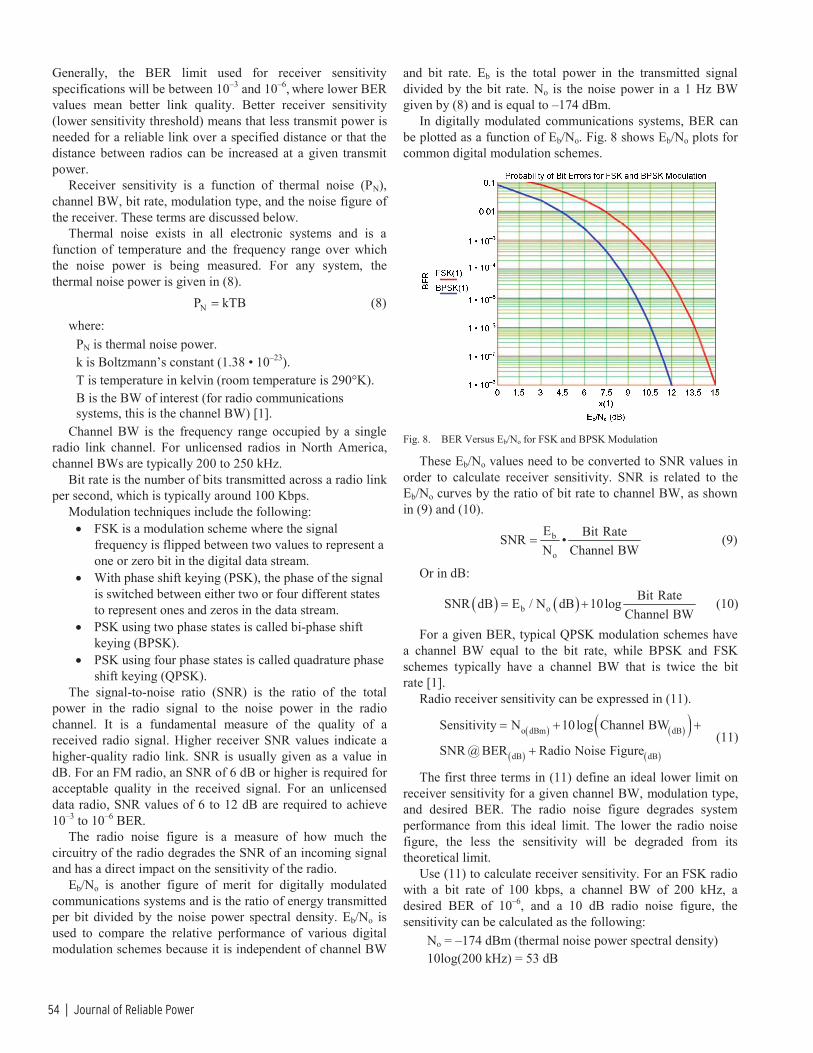
54 | Journal of Reliable Power
Generally, the BER limit used for receiver sensitivity specifications will be between 10–3 and 10–6, where lower BER values mean better link quality. Better receiver sensitivity (lower sensitivity threshold) means that less transmit power is needed for a reliable link over a specified distance or that the distance between radios can be increased at a given transmit power.
Receiver sensitivity is a function of thermal noise (PN), channel BW, bit rate, modulation type, and the noise figure of the receiver. These terms are discussed below.
Thermal noise exists in all electronic systems and is a function of temperature and the frequency range over which the noise power is being measured. For any system, the thermal noise power is given in (8). NP kTB= (8)
where: PN is thermal noise power. k is Boltzmann’s constant (1.38 • 10–23). T is temperature in kelvin (room temperature is 290°K). B is the BW of interest (for radio communications systems, this is the channel BW) [1].
Channel BW is the frequency range occupied by a single radio link channel. For unlicensed radios in North America, channel BWs are typically 200 to 250 kHz.
Bit rate is the number of bits transmitted across a radio link per second, which is typically around 100 Kbps.
Modulation techniques include the following: • FSK is a modulation scheme where the signal
frequency is flipped between two values to represent a one or zero bit in the digital data stream.
• With phase shift keying (PSK), the phase of the signal is switched between either two or four different states to represent ones and zeros in the data stream.
• PSK using two phase states is called bi-phase shift keying (BPSK).
• PSK using four phase states is called quadrature phase shift keying (QPSK).
The signal-to-noise ratio (SNR) is the ratio of the total power in the radio signal to the noise power in the radio channel. It is a fundamental measure of the quality of a received radio signal. Higher receiver SNR values indicate a higher-quality radio link. SNR is usually given as a value in dB. For an FM radio, an SNR of 6 dB or higher is required for acceptable quality in the received signal. For an unlicensed data radio, SNR values of 6 to 12 dB are required to achieve 10–3 to 10–6 BER.
The radio noise figure is a measure of how much the circuitry of the radio degrades the SNR of an incoming signal and has a direct impact on the sensitivity of the radio.
Eb/No is another figure of merit for digitally modulated communications systems and is the ratio of energy transmitted per bit divided by the noise power spectral density. Eb/No is used to compare the relative performance of various digital modulation schemes because it is independent of channel BW
and bit rate. Eb is the total power in the transmitted signal divided by the bit rate. No is the noise power in a 1 Hz BW given by (8) and is equal to –174 dBm.
In digitally modulated communications systems, BER can be plotted as a function of Eb/No. Fig. 8 shows Eb/No plots for common digital modulation schemes.
Fig. 8. BER Versus Eb/No for FSK and BPSK Modulation
These Eb/No values need to be converted to SNR values in order to calculate receiver sensitivity. SNR is related to the Eb/No curves by the ratio of bit rate to channel BW, as shown in (9) and (10).
b
o
E Bit RateSNR •N Channel BW
= (9)
Or in dB:
( ) ( )b oBit RateSNR dB E / N dB 10log
Channel BW= + (10)
For a given BER, typical QPSK modulation schemes have a channel BW equal to the bit rate, while BPSK and FSK schemes typically have a channel BW that is twice the bit rate [1].
Radio receiver sensitivity can be expressed in (11).
( ) ( )( )( ) ( )
o dBm dB
dB dB
Sensitivity N 10log Channel BW
SNR @ BER Radio Noise Figure
= + +
+ (11)
The first three terms in (11) define an ideal lower limit on receiver sensitivity for a given channel BW, modulation type, and desired BER. The radio noise figure degrades system performance from this ideal limit. The lower the radio noise figure, the less the sensitivity will be degraded from its theoretical limit.
Use (11) to calculate receiver sensitivity. For an FSK radio with a bit rate of 100 kbps, a channel BW of 200 kHz, a desired BER of 10–6, and a 10 dB radio noise figure, the sensitivity can be calculated as the following:
No = –174 dBm (thermal noise power spectral density) 10log(200 kHz) = 53 dB

Apply Radios to Improve the Operation of Electrical Protection | 55
SNR for 10–6 BER: from Fig. 8, Eb/No = 13.5; because this radio has a bit rate/BW ratio of 1/2, the SNR will be 3 dB less than Eb/No, so SNR = 10.5 dB.
Receiver Sensitivity –147 dBm 53 dB10.5 dB 10 dB –100.5 dBm
= + ++ =
(12)
E. Receiver Selectivity Selectivity is a measure of the ability of a radio to receive
the desired in-channel signal in the presence of an undesired out-of-channel interfering signal. As with radio sensitivity, selectivity is specified in terms of a desired BER. In addition, it is specified in terms of how close the out-of-channel interfering signal is to the desired channel. The frequency separation of the desired signal and the unwanted signal can be defined in terms of channels or in hertz.
Radio selectivity is determined primarily by the quality of the channel filter used in the design. The steeper the attenuation slope of the channel filter and the better the ultimate out-of-channel attenuation, the better the radio selectivity will be. Selectivity is lowest for the channels immediately adjacent to the desired channel and improves as the frequency separation to the undesired signal increases.
As shown in Fig. 9, radio selectivity is measured by setting the desired in-channel signal level 3 dB above the radio sensitivity level (the received power at which the specified BER is achieved). An out-of-channel interfering signal is then introduced at a specific frequency offset and its power increased until the BER of the in-channel signal increases to the sensitivity limit. The selectivity is defined as the ratio of the out-of-channel signal amplitude to the in-channel signal in dB.
Fig. 9. Receiver Selectivity
F. Antenna Gain and Patterns Antennas are the radiating elements of a radio system that
allow for efficient radio wave propagation. Antennas are passive devices, which do not alter RF signals or amplify the RF power of the radio. At best, they can only radiate as much power as is delivered to their input terminals. The term antenna gain does not refer to amplification of a signal; rather, it is the ability of an antenna to radiate more RF energy in a particular direction than an antenna that radiates RF energy uniformly. The antenna pattern is a graphical view of the relative directivity of the antenna. These can be two-dimensional plots showing radiated power in either a
horizontal or vertical plane or a three-dimensional solid showing radiated power in all directions in space.
Fig. 10 shows the two basic types of antennas: omnidirectional and directional. Omnidirectional antennas, such as a half-wave dipole, have equal radiated power in all directions in a plane perpendicular to the axis of the antenna. The radiation pattern for a vertically oriented dipole looks like a donut without a hole in a horizontal plane with equal gain in all directions in the horizontal plane. Directional antennas, such as multi-element Yagi antennas, are designed to radiate more of their power in one direction than in other directions and have a radiation pattern with a main lobe in one direction that looks like a short, flattened baseball bat with smaller side lobes and a small back lobe in the direction opposite to the main lobe.
Omnidirectional
Directional
Fig. 10. Omnidirectional and Directional Antennas
Directional antenna gains are defined relative to that of an ideal isotropic radiator or a half-wave dipole. An isotropic radiator is a point radiator with a spherical gain pattern having equal radiated power in all directions, as shown in Fig. 11.
Fig. 11. Directional Antenna Gain
The reference value dBi indicates antenna gain relative to an isotropic radiator, while dBd is used to indicate gain relative to a half-wave dipole radiator. A half-wave dipole has a gain of 2.15 dBi. The gain pattern of a directional antenna is defined in terms of beam width in angular degrees from the direction of greatest gain in both the horizontal and vertical directions. The beam width is generally specified as the point at which the gain of the antenna is 3 dB below the maximum.
Antennas are tuned resonant devices, and as such, they operate efficiently within a relatively narrow band of frequencies around the center frequency for which they were designed. The BW of an antenna is usually defined at some low value of voltage standing wave ratio (VSWR), a measure

56 | Journal of Reliable Power
of reflected power, where the majority of the incident power is being radiated by the antenna. Typically, antennas have BWs on the order of 10 percent of their center frequency.
The radiation efficiency of an antenna depends on the impedance match between the transmission line connected to the antenna inputs and the antenna structure itself. Usually, a matching network is designed into the antenna input to achieve a good impedance match. Improper impedance matching adversely impacts the radiation efficiency and/or gain of the antenna. This loss of efficiency affects transmission and reception equally.
Directional antennas are multi-element devices with a single driven element and multiple passive elements. A Yagi antenna (shown in Fig. 12) has a single passive reflector in the direction opposite to the desired radiated direction, a single driven element called a radiator, and one or more passive director elements that help provide the directional gain of the antenna.
Fig. 12. Yagi Antenna
G. Spread-Spectrum Techniques A spread-spectrum system is one where a wider band of
frequencies is utilized to transmit a signal than the minimum required to transmit the desired information. This additional BW is used to provide a reliable communications link in the presence of high-level noise or interfering signals. The Shannon-Hartley channel capacity theorem defines the upper limit of error-free data transmission within a specified BW as (13).
( )2C B• log 1 S / N= + (13)
where: C is the channel capacity in bits per second. B is the channel BW in hertz. S/N is the signal-to-noise power ratio (also referred to as SNR).
This equation can be rearranged to give the minimum SNR to transmit a given data rate in a given BW, as shown in (14).
( )
CB
dBSNR 10• log 2 1⎛ ⎞⎜ ⎟⎝ ⎠
⎛ ⎞⎜ ⎟= −⎜ ⎟⎝ ⎠
(14)
For a fixed data rate C, increasing the BW B means that the minimum SNR for error-free data transmission can be lower. In fact, for values of B greater than C, the SNR can actually be negative, meaning reliable communication can be maintained
with a background noise level higher than the desired signal. Increasing channel BW to allow for reliable communication in the presence of high-level interfering signals and noise is what spread-spectrum techniques are all about.
Spread-spectrum processing provides for expansion of the signal BW by up to several orders of magnitude through a code attached to the communications channel. The ratio between the spread signal BW and the original signal BW (base band [BB]) is known as the processing gain (PG).
A typical spread-spectrum communications system is shown in Fig. 13.
Transmitter
Spread-Spectrum Code
Receiver
Spread-Spectrum Code
Data In Data Out
RF Out RF In
Fig. 13. Spread-Spectrum System
In Fig. 13, both the transmitter and receiver share a predefined spread-spectrum code for successful wireless communication. The incoming data are combined with this code and fed into the transmitter block. At the receiver end, the receiver uses the same code to extract the data from the RF signal.
This can be explained in the frequency domain, as shown in Fig. 14.
Fig. 14. Signal Spreading
In the transmit block, the incoming data at the BB rate go through the spreading and modulation operations and are “spread” in frequency, as well as shifted in frequency (for wireless transmission). At the receiver end, despreading and demodulation operations are performed to extract the original data, as shown in Fig. 15.
Despreading + Demodulation +
Frequency Shifting
FrequencyData In (BB • PG)
Data In (Spread-Spectrum Code)
RF Carrier
Data In (BB)Frequency
Fig. 15. Signal Despreading
There are several different spread-spectrum techniques available today, distinguished by the point where the spread-spectrum code is injected into the communications channel.
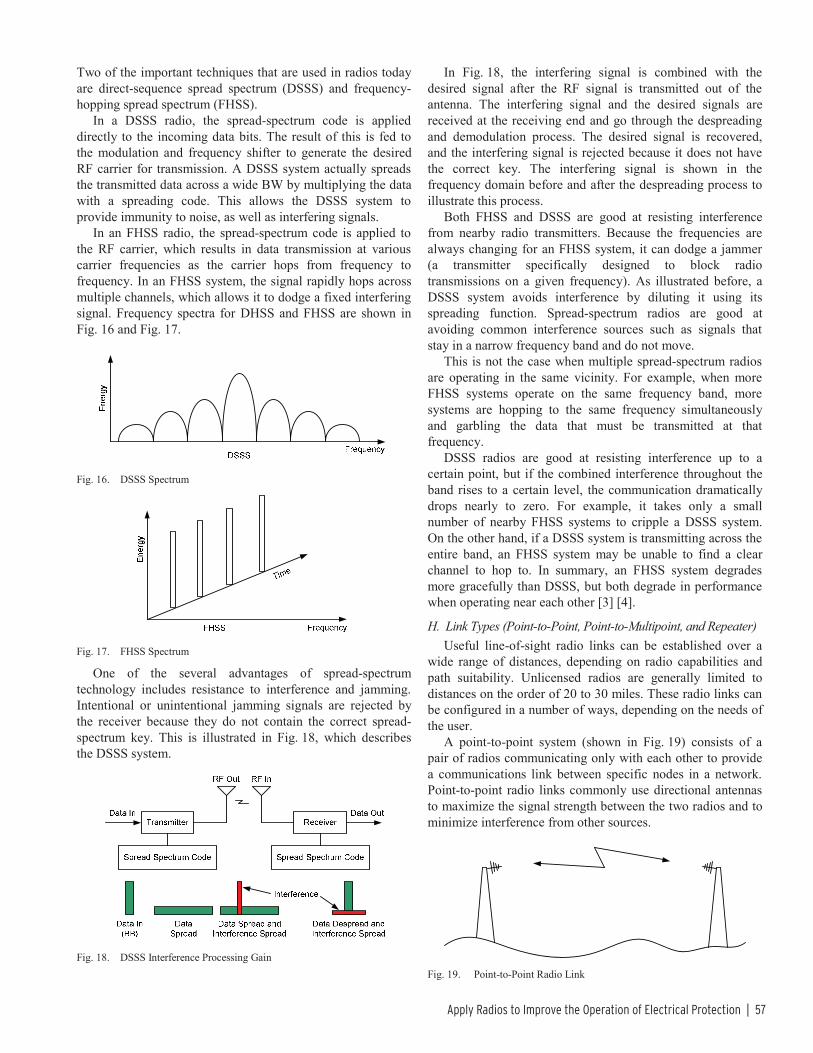
Apply Radios to Improve the Operation of Electrical Protection | 57
Two of the important techniques that are used in radios today are direct-sequence spread spectrum (DSSS) and frequency-hopping spread spectrum (FHSS).
In a DSSS radio, the spread-spectrum code is applied directly to the incoming data bits. The result of this is fed to the modulation and frequency shifter to generate the desired RF carrier for transmission. A DSSS system actually spreads the transmitted data across a wide BW by multiplying the data with a spreading code. This allows the DSSS system to provide immunity to noise, as well as interfering signals.
In an FHSS radio, the spread-spectrum code is applied to the RF carrier, which results in data transmission at various carrier frequencies as the carrier hops from frequency to frequency. In an FHSS system, the signal rapidly hops across multiple channels, which allows it to dodge a fixed interfering signal. Frequency spectra for DHSS and FHSS are shown in Fig. 16 and Fig. 17.
Fig. 16. DSSS Spectrum
Fig. 17. FHSS Spectrum
One of the several advantages of spread-spectrum technology includes resistance to interference and jamming. Intentional or unintentional jamming signals are rejected by the receiver because they do not contain the correct spread-spectrum key. This is illustrated in Fig. 18, which describes the DSSS system.
Fig. 18. DSSS Interference Processing Gain
In Fig. 18, the interfering signal is combined with the desired signal after the RF signal is transmitted out of the antenna. The interfering signal and the desired signals are received at the receiving end and go through the despreading and demodulation process. The desired signal is recovered, and the interfering signal is rejected because it does not have the correct key. The interfering signal is shown in the frequency domain before and after the despreading process to illustrate this process.
Both FHSS and DSSS are good at resisting interference from nearby radio transmitters. Because the frequencies are always changing for an FHSS system, it can dodge a jammer (a transmitter specifically designed to block radio transmissions on a given frequency). As illustrated before, a DSSS system avoids interference by diluting it using its spreading function. Spread-spectrum radios are good at avoiding common interference sources such as signals that stay in a narrow frequency band and do not move.
This is not the case when multiple spread-spectrum radios are operating in the same vicinity. For example, when more FHSS systems operate on the same frequency band, more systems are hopping to the same frequency simultaneously and garbling the data that must be transmitted at that frequency.
DSSS radios are good at resisting interference up to a certain point, but if the combined interference throughout the band rises to a certain level, the communication dramatically drops nearly to zero. For example, it takes only a small number of nearby FHSS systems to cripple a DSSS system. On the other hand, if a DSSS system is transmitting across the entire band, an FHSS system may be unable to find a clear channel to hop to. In summary, an FHSS system degrades more gracefully than DSSS, but both degrade in performance when operating near each other [3] [4].
H. Link Types (Point-to-Point, Point-to-Multipoint, and Repeater) Useful line-of-sight radio links can be established over a
wide range of distances, depending on radio capabilities and path suitability. Unlicensed radios are generally limited to distances on the order of 20 to 30 miles. These radio links can be configured in a number of ways, depending on the needs of the user.
A point-to-point system (shown in Fig. 19) consists of a pair of radios communicating only with each other to provide a communications link between specific nodes in a network. Point-to-point radio links commonly use directional antennas to maximize the signal strength between the two radios and to minimize interference from other sources.
Fig. 19. Point-to-Point Radio Link

58 | Journal of Reliable Power
A point-to-multipoint scheme involves a network of radios with a master (M) communicating with a number of remote sites (R1, R2, R3, and R4), as shown in Fig. 20. Point-to-multipoint schemes generally use an omnidirectional antenna for the master because of the need to broadcast the signal widely.
Fig. 20. Point-to-Multipoint Radio Link
A repeater uses multiple radios in a point-to-point scheme to establish a link where a single line-of-sight path is not viable. The repeater radios are set up at an intermediate point (or points) in the path between the ends of the link to relay the signals farther along to the opposite end of the link or to another repeater along the path. Repeaters are used where line of sight between the ends of the link is obscured or where the length of the path exceeds the range of a single pair of radios. This type of scheme is shown in Fig. 21 and uses directional antennas to maximize gain and minimize interference.
Fig. 21. Radio Repeater Link
III. SYSTEM PARAMETERS FOR POWER SYSTEM PROTECTION When applying radio technology in protection and control
applications, many factors play a large role in overall system performance and should be considered. Unlicensed radio systems have the advantage of costing much less than using fiber or pilot wires, but there are new challenges to making the radio channel meet the same requirements as cabled solutions. The following five items should be evaluated when selecting radios for protection and control applications:
• Latency • Availability • Security and dependability • Robustness in harsh environments • Encryption
A. Latency Minimizing the latency of the radio link is critical for high-
speed operations. Early radios for the control market did not suit these applications because the radios were designed for sending large amounts of data with buffering to overcome channel unavailability. This buffering caused large delays in operation and, in some instances, led to undesired operations. Newer radios now have operating modes that allow buffering to be turned off or have special operation modes to support specific protocols designed for control. Selection of protocol and radio latency, together, have a large effect on system performance and overall latency.
When using radio for a pilot protection scheme or for high-speed control, the maximum allowed radio latency varies from 1.5 to 2 cycles. When evaluating radio latency, it is important to know the minimum and maximum latency for a good radio link. Very popular spread-spectrum radios always have a variable latency and, depending on how the manufacturer designed the radio, will exhibit a small or large variability in latency. The latency, along with the availability of the link, provides the real average, minimum, and maximum latency expected for a given operation.
B. Availability Radio link availability is the ratio of the time the radio link
provides good data to the total time the radio transmits data. Radio link availability varies from one radio manufacturer to another and from one link to another. Link availability is usually given by the radio after it has been in operation. There are several ways manufacturers calculate radio link availability, but all yield close to the same results. Calculation of availability can be made on just the protocol data transferred or on the complete frame or radio link. Availability is given in percentage and can go down to the detail of per-frequency availability. For either method, the link should be set up and run for at least a few days before using the availability numbers for long-term operation (for initially aiming the antennas, 10 to 20 minutes of operation is sufficient). Longer periods of successful in-service operating time yield higher availabilities. For protection and control applications, the widely accepted requirement for radio link availability is from 95 percent to 99.95 percent. This equates to between 265 minutes and 438 hours of outage per year. An availability of 95 percent is suitable for improving power quality or speeding up control with primary operation already in place. An availability of 99.95 percent is sufficient for transmission lines requiring redundant protection systems. The availability and latency are used to calculate overall system performance [5].
C. Security and Dependability Better link availability directly improves dependability.
Better dependability indicates that when the system is called upon to operate, it will operate within the latency required for the system in the presence of interference or noise. As

Apply Radios to Improve the Operation of Electrical Protection | 59
availability decreases, dependability also decreases, so the system will not operate as needed. IEC 60834-1 references how to calculate and test the dependability and security of a system.
The security of a system is the ability of a link to properly operate when called upon and not operate when not called upon. Radio link security is highly dependent on the protocol used. Security is defined in IEC 60834-1 and can be calculated using (15).
uu
Err
NP
N≈ (15)
where: Pu is the probability of an unwanted command, and 1 – Pu is the security. Nu is the number of unwanted commands. NErr is the number of error bursts in the communications channel.
Radio link security is highly dependent on the protocol used and the error detection capabilities of the radio. The radio manufacturers should provide these numbers for specific radios and specific protocols [6].
D. Robustness in Harsh Environments Radio hardness and robustness are important for reliable
and dependable operation. The radio should meet the same type test standards and temperature requirements applied to relays. The scheme is only as good as the weakest link. Radios used in protection and control applications should meet or surpass the requirements of IEEE 1613, which lists all of the type tests needed to validate that a device is rugged enough to use for communication in electric power substations.
E. Encryption Providing a secure communications link that cannot be
compromised or manipulated by outsiders is important when using radio communication for sensitive information. Spread-spectrum and frequency-hopping techniques to some extent make it more difficult for an outsider to detect and decode a radio link, but they do not provide real data security. It is quite simple for someone using modern detection equipment to lock on to and decode either a DSSS or FHSS link. Encryption must be employed to provide data security.
Encryption is the process of using an algorithm, called a cipher, to transform user information into an unreadable form to prevent access and use of that information by anyone who does not possess the cipher key. Historically, encryption techniques have relied on substitution (substituting a different letter or block of letters of the alphabet for the original letter or block of letters with a substitution key available to the sender and receiver) and rearrangement, also known as permutation (rearrangement of letters in the original text according to a predefined key).
Modern electronic encryption algorithms continue to use these techniques in a much more sophisticated manner to provide cybersecurity for the power industry. The Advanced Encryption Standard (AES) encryption algorithm is widely
used today because of the security it provides and because it can be implemented efficiently in either hardware or software. This algorithm employs a symmetric key encryption standard with multiple transformation levels, each consisting of substitution and permutation processes, including one that relies on the encryption key. The algorithm operates on data blocks of 128 bits using a key of 128, 192, or 256 bits. This algorithm has been used by the United States government to protect data up to the top-secret level. The longer the key, the more levels of transformation are used in the algorithm and the more secure the encryption process will be.
Academic analysis (attack) of the AES algorithm has generated much debate about whether it can ultimately be broken, but leading experts do not believe that a practical method of intercepting AES encrypted data will ever be found. However, the ultimate weakness of any encryption scheme is user carelessness about security and access to the key. If hackers can obtain the key used in an encryption scheme, they have defeated the security as effectively as if they had broken the cipher itself and with infinitely less effort.
Secure, reliable, and dependable wireless systems require more initial work than wired systems. The IEEE 1613 and IEC 60834-1 standards still apply when using wireless links for communication and can help to guide the design of protection and control schemes. Working closely with manufacturers and using the available standards and information in radios help ensure acceptable radio system performance.
IV. RADIO APPLICATIONS
A. ITU Regions Radio regulations are determined on a country-by-country
basis. There is no overarching international body with legal authority. Instead, countries meet every four years in the World Radiocommunications Conference (WRC) organized by the International Telecommunications Union (ITU). These meetings produce recommendations that must be adopted by each country to have the effect of law. Some countries are close together or share common borders. Other countries are far from each other. To simplify the coordination, the ITU splits the world into three radio regions, as shown in Fig. 22. North and South America, including the Caribbean, are located in Radio Region 2.
Fig. 22. ITU World Radio Regions

60 | Journal of Reliable Power
B. Licensed Versus Unlicensed Radios All radio designs must be certified by the national body
before they can be used in a country. This is usually done by the manufacturer or by an importer for foreign-manufactured radios. To use a radio, a license is generally required; multiple radios may require multiple licenses.
There are a limited number of frequency bands that are unlicensed or lightly licensed. The most significant are the industrial, scientific, and medical (ISM) bands. In Radio Region 2, the best known ISM bands are the 915 MHz band, 2.4 GHz band (used for Wi-Fi®), and 5.8 GHz Unlicensed National Information Infrastructure (UNII) band. For communications applications, these bands generally use some form of spread-spectrum technology to limit the effects of interference.
C. FCC, IC, and COFETEL Inside the North American Free Trade Agreement
(NAFTA), each of the three countries has its own governmental body that regulates radio use. In Canada, it is Industry Canada (IC); in Mexico, it is the Comisión Federal de Telecomunicaciones (COFETEL); and in the United States, it is the Federal Communications Commission (FCC). These three bodies create regulations for different parts of the radio spectrum. The decisions are based on government decisions that balance national interests, consumer interests, international agreements (such as those in aviation), industry requirements, WRC recommendations, and cooperation with neighbors.
The most useful bands for electric protection systems and key subbands are described in Table I.
TABLE I IMPORTANT RADIO BANDS FOR UTILITY USE
Frequency Wavelength Band Description
30 to 300 MHz 10 to 1 m VHF Very high frequency.
300 to 3,000 MHz
1,000 to 100 mm UHF
Ultra high frequency. Various 400 MHz ISM bands
(RR1, RR3*). 868 short-range device (SRD)
bands (RR1, RR3*). 915 MHz ISM band (RR2*).
2.4 GHz ISM band. 3.65 GHz utility band (USA).
3 to 30 GHz 100 to 10 mm SHF Super high frequency.
5.8 UNII band. *RR1, RR2, and RR3 are ITU Radio Regions 1, 2, and 3.
D. Protection Engineer Perspective Not all radios can be used in all parts of the world.
Coordination by radio region provides some level of regional commonality. Cooperation between the United States and Canadian governments and increasing coordination with Mexico, due to NAFTA, are driving a growing set of product offerings that can be used across all three countries. A protection engineer working within a single country needs to
use the most appropriate band available in that country and make sure that radios are authorized for use in that country. Protection engineers working across country lines are still responsible to make sure individual radio types are approved in each country where they will be used. Using the same radios across NAFTA countries and nearby neighbors is becoming easier as cooperation between authorities increases.
V. SETTING UP RADIO LINKS There are many tools available to help set up a radio link
without a large initial investment and extensive knowledge about radios. The first step is a path study. Most radio manufacturers offer a free path study. This path study does not guarantee the link will work but helps to determine if the radio link is viable. Path study software uses terrain data, clutter data, radio-specific information, antenna design, and antenna tower height to calculate the path study. The terrain data include the elevations at different locations. The clutter data include an approximation of the vegetation height within defined regions. Most path studies do not take into account buildings or other man-made obstacles. These obstacles must be manually added to the path study.
The geographic information system (GIS) coordinates of an antenna tower and the maximum height of the mounted antennas are required inputs to the path study. The results of the study include the availability of the link and the link budget. Other inputs to a path study include radio hardware and antenna design details. The availability number given by the path study is an approximation of how well the link will work based upon propagation and multipath calculations. The initial target availability should ideally be greater than 99 percent. Again, this number is an approximation based upon the data entered, so actual results will vary.
The other important output of a path study is the fade margin. This is the difference between the received signal strength and the maximum sensitivity of the radio. To maintain a good link while minimizing radio interruptions, it is recommended to have at least 20 dB of margin. This margin decreases the likelihood that the received power level will degrade below the receiver sensitivity due to variable environmental effects, vegetation growth, or radio interference. Lower radio link margins will still work but can affect the long-term availability of the system.
An example of a link budget is shown in (16). T AT P AR F SP G L G M R+ + + − ≥ (16)
where: PT is transmit power. GAT is the transmitter antenna gain. LP is the path loss between the transmitter and receiver. GAR is the receiver antenna gain. MF is the fade margin. RS is the specified receiver sensitivity.
The inequality indicates that the sum of the elements on the left-hand side of the equation has to be greater than the radio receiver sensitivity in order to establish a reliable radio link.

Apply Radios to Improve the Operation of Electrical Protection | 61
A wide selection of antennas is available for ISM bands. Most manufacturers offer antennas that are best suited for the application and tested to meet FCC regulations. Most point-to-point links use high-gain Yagi antennas to transmit wireless information long distances over a narrow beam. Typical ISM band Yagi antennas have gains that range from 3 dB to 12 dB. A higher-gain antenna has a narrower beam and propagates the signal farther than a lower-gain antenna. Yagi antennas have gain on both transmitting and receiving sides. It is best to let the manufacturer choose the antenna based upon the path study. Other antennas may be used, but careful attention is needed to avoid violating regulations.
When setting up protection or control radio links, special care must be taken to ensure the reliability and dependability of communication beyond that required for supervisory control and data acquisition (SCADA) links. Choosing the right Yagi antenna and properly aiming the antenna are more critical in protection and control applications than when using radios for SCADA data collection. A Yagi antenna can be either vertically or horizontally polarized. The direction of polarization is the direction of the Efield radiated by the antenna.
Using oppositely polarized antennas on different radio links allows 20 dB of separation between signals on adjacent frequencies and helps reduce interference between radio links operating in close proximity to one another. Using the signal strength and availability is the key to creating a good radio link. The quickest way to commission a radio is to use the received signal strength indication (RSSI). The higher the RSSI value, the stronger the signal. Once both antennas are positioned with the highest RSSI, the radio link should be allowed to run for 10 or more minutes. After 10 minutes, the antennas should be aimed in different directions in 5-degree increments. When the measured availability is the highest at both ends, the antennas are aligned for the best performance. Any time the availability is less than 100 percent, there is either interference from environmental factors or other radios or multipath interference. Although directional antennas concentrate the majority of power from a radio transmitter along the line-of-sight path of the radio link, some of the signal can be scattered by objects (such as buildings, trees, and land cover). This scatter causes multiple images of the transmitted signal to reach the receiving antenna from more than one path. If these multipath signals sum out of phase with the desired signal, they can weaken the signal to the point that the receiver cannot detect it or will generate a high number of bit errors. When this happens, the radio error detection rejects the data. This is undesirable if a control signal must be sent at that instant of time. If the radio is set up for SCADA data use, the radio will detect the error and resend the message, and the end devices will never see the missing data. Aiming the antennas and minimizing multipath interference yields better dependability.
It can be desirable to set up multiple point-to-point links in substations requiring protection on each line. It is very convenient and inexpensive to set up multiple radio links with
multiple antennas located on the same antenna tower. This setup requires much more attention and careful antenna placement to approach the same performance levels as one dedicated point-to-point link. For example, for a pilot scheme using a radio link on each transmission line, it is easy to place three or more radio links at the substation to the other end of the line of a different substation. Ideally, it would be economical to place all three antennas on one pole. Placing multiple antennas on the same pole operating at the same frequency band can result in interference, with a significant impact on radio link performance. When one antenna at a shared site with multiple radio links is transmitting at 36 dBm and an adjacent antenna is trying to receive a signal from a remote location at –80 dBm, interference from the transmitting signal degrades receiver availability. The antenna transmitting at a high level overpowers the lower-level received signal from the remote location. There are several options to reduce the effect of interference between multiple radio links at a shared site, but these do not entirely eliminate the problem. Changing the polarization of the antennas provides a 20 dB improvement in isolation between a pair of radio links. For three antennas, increasing the separation between them will always help, as will reducing the transmit power. However, reducing the transmit power reduces availability, operating times, and dependability. One method to overcome this problem is to synchronize spread-spectrum radios at the shared location so they transmit and receive at exactly the same time. Radio synchronization reduces radio-to-radio interference to the level of difference in the received signals, which is generally less than 20 dB. Most radios on the market can properly reject adjacent signals at this level. Polarizing and moving the antennas farther apart will give even better results. Synchronizing the radios greatly improves availability and provides performance comparable to a single dedicated radio link.
VI. ECONOMIC BENEFITS The most basic electrical protection schemes operate
without the use of communication. Adding communication results in more accurate coverage and faster operation. Faster operation reduces stress on electrical components and improves overall power system stability and reliability. Better accuracy in coverage helps the protection scheme define where the event is located and reduces the probability of incorrect operation.
There are many different methods for providing communication in protection schemes. Often, a primary consideration is the communications system. A utility can lease communications or install their own. In the first case, the utility relinquishes some control and must pay monthly fees but does not have to make a capital investment in the communications infrastructure. For utility ownership, fiber-optic cable is the gold standard, but fiber is expensive. Hanging fiber-optic cable on poles is less expensive than burying fiber-optic cables. Rocky terrain and dense urban

62 | Journal of Reliable Power
infrastructure increase underground installation costs where sophisticated, horizontal-boring equipment may be required. Fig. 23 provides some cost comparisons of different methods.
Fig. 23. Comparisons of Cost Per Mile for Communication
If two line terminals are several miles apart, the cost of fiber can be high, especially if the terrain is difficult. Power-line carrier is attractive because no new lines have to be laid. The cost of the connection equipment is high and increases more rapidly with the voltage level on the transmission line. In one case of a 69 kV line, the power-line carrier equipment was approximately $400,000. Leased communications come with monthly bills that add up over the long life of electric utility installations. These tradeoffs make radio attractive because fast communication is achieved without any form of wiring between line terminals. The speed of radio waves in air is close to the speed of light, so any delays are due to radio and protection electronics at each end.
A utility has a choice of licensed and unlicensed radios. Licensed radios require longer planning lead times because they cannot be placed in service until the licensing process is complete. Spectrum coordination and licensing costs are all complicating factors. By contrast, unlicensed radios can be deployed immediately. Use of highly directional antennas and spread-spectrum technology limit the effects of interference. In fact, in the ISM bands, radios are required to tolerate interference generated by other sources. In all cases, radio use must be accompanied by proper radio link design, including path studies, noise floor measurement, antenna selection, and location. There are a few cases where radios will not be an appropriate solution.
The benefits of using ISM band radios can be summarized as the following:
• Ease of deployment (no license costs or delays). • Reduced interference (due to technology). • Optimized air interface for protection applications.
VII. CONCLUSION Electric utilities can save money and improve system
reliability by using radio communications in electrical protection schemes. The flexibility of radio and the low planning overhead associated with ISM radios are well-suited to different parts of the electrical supply system, including transmission, distribution, and emerging distributed generation applications. With the tools described in this paper, protection
and communications engineers can deploy radio systems with the reliability required for protection and control. Radio economics are particularly interesting for systems where capital investment is at a premium, such as in rural electric systems, emerging economies, and locations with difficult terrain.
VIII. REFERENCES [1] J. Zyren and A. Petrick, “Tutorial on Basic Link Budget Analysis,” June
1998. Available: http://www.sss-mag.com/pdf/an9804.pdf. [2] “Overview of Propagation Theory,” adapted from L. E. Miller,
Propagation Model Sensitivity Study, J. S. Lee Associates, Inc. Contract Report, July 1992. Available: http://w3.antd.nist.gov/wctg/manet/ propthy_r1.pdf.
[3] Maxim Integrated Products, “An Introduction to Spread-Spectrum Communications,” February 2003. Available: http://www.maxim-ic.com/an1890.
[4] R. C. Dixon, Spread Spectrum Systems with Commercial Applications, 3rd Edition, New York: John Wiley & Sons, Inc., 1994.
[5] IEEE/PSRC Working Group H2, “Using Spread Spectrum Radio Communication for Power System Protection Relaying Applications,” A Report to the IEEE Power System Relaying Committee, July 2005.
[6] Teleprotection equipment of power systems – Performance and testing – Part 1: Command systems, Section 2 Characteristics of command type teleprotection systems, IEC 60834-1, 1999.
IX. BIOGRAPHIES Shankar V. Achanta received his MS in electrical engineering from Arizona State University in 2002. He joined Schweitzer Engineering Laboratories, Inc. (SEL) in 2002 as hardware engineer developing electronics for communications devices, data acquisition circuits, and switch mode power supplies. Shankar received a patent for a self-calibrating time code generator while working at SEL. He currently holds the position of development manager for the precise time and communications group at SEL.
Brian MacLeod has many years of varied experience in product development and technical marketing roles in the United States and Great Britain. He is a member of the IEEE Communications Society, the IEEE Computer Society, and the IEEE Standards Association. He served as a voting member of the IEEE 802.3 Working Group (Ethernet networking) for over ten years. He was a consultant for several years before joining Schweitzer Engineering Laboratories, Inc. and was a key member of the management team of Packet Engines (the pioneer of Gigabit Ethernet technology). Earlier in his career, Brian worked for major companies, including NCR Corporation, EMI Electronics, and Veeder-Root Ltd. He holds a diploma in electrical and electronic engineering from Glasgow College of Technology in Scotland.
Eric Sagen received his BS in electrical engineering from Washington State University in 1997. He joined General Electric in Pennsylvania as a product engineer. In 1999, Eric was employed by Schweitzer Engineering Laboratories, Inc. as a distribution product engineer. Shortly after, he was promoted to lead distribution product engineer. Eric transferred to the time and communications group in 2006 and is currently a lead product engineer. He is certified in Washington as an Engineer in Training (EIT).
Henry Loehner received his BS in electronic engineering from Cal Poly San Luis Obispo in 1983. He worked at Hewlett Packard and Agilent Technologies for 25 years as a radio frequency design engineer and research and development project manager, developing test and measurement equipment for the cellular telephone industry. While working for Hewlett Packard, Henry received a patent for an electronic step attenuator design. He joined Schweitzer Engineering Laboratories, Inc. in 2010 and is currently working as a lead radio frequency design engineer.
© 2010 by Schweitzer Engineering Laboratories, Inc. All rights reserved.
20100908 • TP6450-01

IEC 61850: What You Need to Know About Functionality and Practical Implementation | 63
IEC 61850: What You Need to Know About Functionality and Practical Implementation
David Dolezilek, Schweitzer Engineering Laboratories, Inc.
Abstract—Today, all utility users and manufacturers recognize the desire and the need to merge the communications capabilities of all IEDs in a substation, or even across the entire power network. This wide-area interconnection can provide not only data gathering and setting capability, but also remote control. Furthermore, multiple IEDs can share data or control commands at high speed to perform new distributed protection, control, and automation functions. This sort of cooperative control operation has the potential to supersede and eliminate much of the dedicated control wiring in a substation, as well as costly special-purpose communications channels between the stations and around the power network.
Many utilities have already installed systems of interconnected IEDs, which provide some degree of centralized substation and system monitoring and control. In practice, the majority of information available in installed IEDs is abandoned and left uncollected because traditional integration techniques were designed to exclusively support SCADA. Rather than being conceived as another protocol, IEC 61850 was created to be an internationally standardized method of communications and integration with goals of supporting systems built from multi-vendor IEDs networked together to perform protection, monitoring, automation, metering, and control. This paper is the second in a series documenting the evolution of the IEC 61850 standard. The first paper, titled “Significant Substation Communication Standardization Developments,” was written in early 2000. It provides a complete introduction to IEC 61850, discusses the harmonization with UCA, provides terms and definitions, and remains a useful resource.
Using the knowledge gained from numerous network designs, this paper focuses on the realities of actual implementation. Parts one through seven of the IEC 61850 standard deal with the abstract concepts of data groupings and naming conventions so that information is associated and described in the same fashion regardless of the vendor. When putting the abstract concepts of the standard on a physical network, as described in parts eight and nine, details emerge that need to be addressed. This paper identifies contemporary observations, documents several implementation lessons learned, and provides recommendations.
I. INTRODUCTION The International Electrotechnical Committee (IEC)
Technical Committee (TC) 57 was established in 1964 because of an urgent need to produce international standards in the field of communications between the equipment and systems for the electric power process, including telecontrol, teleprotection, and all other telecommunications that control the electric power system.
Having to take into consideration not only equipment aspects, but more and more system parameters, the scope was modified to prepare standards for power system control equipment and systems, including supervisory control and data acquisition (SCADA), energy management systems
(EMS), distribution management systems (DMS), distribution automation (DA), teleprotection, and associated communi-cations.
The technical experts of 22 participating countries have recognized that the increasing competition among electric utilities caused by the deregulation of energy markets requires more productivity and efficiency from electric power systems. The integration of equipment and systems for controlling the electric power process into complete system solutions is needed to support the utilities’ core processes. Equipment and systems have to be interoperable. Interfaces, protocols, and data models must be compatible to reach this goal.
Since the publication of the first paper, it has become obvious that this standard also needs to support substation automation (SA), asset management, equipment monitoring, wide-area monitoring and control, reliability-centered maintenance (RCM) as well as the associated data-access security. It is also likely that this standard will be one of the vehicles to support reliability management and reporting in the wake of recent blackouts. Data to support these applications are often referred to by others as “non-operational data” because they are not used for commanded control operation today. This term may be familiar, but is inaccurate because many of these data will be used in the future to operate the power system in innovative ways.
Communications traffic on actual substation Ethernet LANs will not be limited to the handful of protocols within the IEC 61850 standard. Substation Ethernet LANs will also support traffic for web server applications in IEDs and HMIs; nonstandard IED protocols such as vendor specific, Modbus IP, and DNP IP, email; legacy SCADA protocols such as IEC 60870; vendor-specific IED configuration and diagnostic applications; network analyzer configuration and diagnostic applications; telephone and camera applications, etc.
A. Choice of Ethernet LAN When communications connections are made between
integrated IEDs, a trusted, physically distinct local area network (LAN) is created. LANs are created from copper, fiber, and/or wireless media connected in a star or multidrop fashion. LANs are created from EIA-232, EIA-485, Ethernet, and/or various other connections supporting one or many protocols. Hybrid LANs are made from collections of all of these components such that the IEDs interact with one another as if they were all directly connected locally to one another. One or two integrated devices on a pole top comprise a small LAN. Large LANs are created by directly connecting, or

64 | Journal of Reliable Power
bridging, one or more physically separate LANs together using trusted connections.
The design choice within IEC 61850 to use Ethernet was made to leverage the emerging Ethernet technologies being developed for multiple industries. In addition, it makes use of common and familiar visibility tools (such as browsers) and devices that already exist within utility business networks (such as switches, routers, and Ethernet cable). However, the common misunderstanding of direct Ethernet connections between client and IED has also migrated to our market from other industries. Modern Ethernet LANs are most often implemented as star topology, even though they are often logically represented as direct connections. This difference is important to understand during design so that reliability, performance, data latency, and cost of the Ethernet devices are considered. Fig. 1 illustrates the difference between logical and actual representations of Ethernet LANs.
ClientEthernet Hub or
Switch
Client
IEDs
Logical Ethernet Bus Topology
IEDs
Actual Ethernet Star Topology
Fig. 1. Logical Versus Actual LAN
Briefly, other issues that need to be addressed when designing a network that uses Ethernet include:
• Reaction of networked automation and protection during Ethernet failure
• Communication and IED performance during data storm, hacking, and denial of service attack
• Accidental network overload caused by outside connection or newly connected IED, technician laptop, or test device
• Functionality of IED if the same CPU is performing protection and network communications - It is possible for single CPU designs to suspend
protection while servicing network communication requests
B. Station and Process LAN Within the standardization work, two separate substation
LANs are being considered: the station LAN and the process LAN or bus. The station LAN connects all of the IEDs to one another and to a router or other device for communicating outside the substation onto a wide area network (WAN). The process LAN conveys unprocessed power system information (voltage and current samples and apparatus status) from switchyard source devices to the relays or IEDs that process the data into measurements and decisions. For the process LAN, future developments may include microprocessor-based data acquisition units (DAUs), which will act as Current Transformers (CTs), Potential Transformers (PTs), and status indicators. These forward data via a communications connection to the IED rather than the traditional hard-wired method. When these data are communicated over fiber
connections, isolation is provided between the DAU and the IED. Each individual DAU, such as a CT, is capable of providing data to several IEDs, such as protective relays. DAUs also include intelligent processors imbedded directly in the switch or circuit breaker and merging units (MUs) that merge data from several devices such as CTs or PTs and communicate the values on the process LAN. It is also possible to merge the station and process LANs into one physical communications network.
Peer-to-peer communications are accomplished through direct physical connections or via a virtual direct connection passing through multiple network connections.
A station LAN with all IEDs on one segment and a multiple-segment process LAN design is shown in Fig. 2. A merged station and process LAN is shown in Fig. 3.
HMI DistributedController
Ethernet Switch
PrimaryProtection
Feeder 1
BackupProtection
Feeder 1
DisconnectSwitch
Feeder 1
CircuitBreaker
Feeder 1
MergingUnit
Feeder 1
PrimaryProtection
Feeder 2
BackupProtection
Feeder 2
DisconnectSwitch
Feeder 2
CircuitBreaker
Feeder 2
MergingUnit
Feeder 2
Ethernet Switch Ethernet Switch
StationLAN
ProcessLAN
Fig. 2. Station LAN and Multiple-Segment Process LAN Design
HMI DistributedController
Ethernet Switch
PrimaryProtection
Feeder 1
BackupProtection
Feeder 1
DisconnectSwitch
Feeder 1
CircuitBreaker
Feeder 1
MergingUnit
Feeder 1
PrimaryProtection
Feeder 2
BackupProtection
Feeder 2
DisconnectSwitch
Feeder 2
CircuitBreaker
Feeder 2
MergingUnit
Feeder 2
Ethernet Switch Ethernet Switch
StationLAN
ProcessLAN
Fig. 3. Merged Station and Process LAN Design
C. External Substation Connections The IT products in the substation facilitate easy connection
to other corporate systems through WAN or Internet connections. These connection possibilities highlight the importance of securing data access connections into the substation LAN. Fig. 4 shows a previous substation network design with the addition of external connections.

IEC 61850: What You Need to Know About Functionality and Practical Implementation | 65
HMI DistributedController
Ethernet Switch
PrimaryProtection
Feeder 1
BackupProtection
Feeder 1
DisconnectSwitch
Feeder 1
CircuitBreaker
Feeder 1
MergingUnit
Feeder 1
PrimaryProtection
Feeder 2
BackupProtection
Feeder 2
DisconnectSwitch
Feeder 2
CircuitBreaker
Feeder 2
MergingUnit
Feeder 2
Ethernet Switch Ethernet Switch
StationLAN
ProcessLAN
Router
ToInternet
To WAN
Fig. 4. External Connections to Substation Communication Network
D. Logical Nodes, Logical Devices, and Physical Devices A logical node (LN) is a collection of data objects, data set
objects, descriptive attributes, report-control objects, log-control objects, log objects, and a list of sampled values which define the boundaries of an entity and its state and behavior. The identification and description explicitly and uniquely identifies each data object within an IED in a standard way. In this way, data objects are uniformly defined by name and function across all IEDs. Logical node classes, data object classes, and their relationship in the context of substations and feeder equipment are defined and used to build the hierarchical names and groups that reference the objects in the IEDs. An example includes IEEE elements, such as LN “distance protection” with LN class name “PDIS” and IEEE number 21.
Peer-to-peer messaging is accomplished with two compliant messages that differ slightly. These two messages, GOOSE and GSSE, are collectively referred to as GSE.
Within IEC 61850, the abstract communications service interface (ACSI) was created to standardize the access to instrumented and calculated data stored in the LN logical groupings. The LNs were designed to represent monitoring and control of power system apparatus without regard for which IEDs, DAUs, and merging units they would reside in. This was done intentionally so that the IEC 61850 standard did not dictate the collection of IEDs required for each protection and monitoring application and ensured that multivendor solutions were possible. The ACSI describes how the data are collected but not where they reside. Therefore, a single multifunction IED can serve LNs for several applications, such as the following:
• Protection for more than one feeder • Control of more than one feeder • Reclosing • Metering for more than one feeder • Station battery monitoring • Breaker monitoring for more than one feeder breaker In this way, designers can choose any combination of IEDs
so long as they collectively serve all the necessary LNs. Therefore, at the abstract data level, one solution with two multifunction IEDs can be made equivalent to another solution with five or more single-function IEDs. These can
represent two solutions from one vendor, two solutions with one from each of two vendors, or even several solutions with each IED from a different vendor.
Also, the standard was designed to specifically include source IEDs, DAUs, and merging units that do not speak IEC 61850. These devices use various other methods to communicate data to server IEDs or gateways that do support IEC 61850 via the ACSI. These IEC 61850 ACSI server IEDs and gateways map the source data into the appropriate LNs. Server IEDs represent data from DAUs, merging units, or source IEDs as LNs in addition to the LNs they create for locally instrumented or calculated data. Gateways simply create and pass on LNs for the source IED data.
As shown in Fig. 5, LNs may reside directly in the source IED, in a gateway, or in a combination of the two, known as a server IED. The LNs are the same, regardless of where they exist. However, if all of the LNs are in one server IED, they all share the same IP address.
ACSI Server
Ethernet Switch
IED
StationLAN
All Logical Nodes
ACSI ClientHMI
Logical Nodes
ACSI Server
Gateway orServer IED Plus
Logical IED
Logical Nodes
Physical IED
IED
TraditionalCommunications
Fig. 5. ACSI Server Locations
The standard is most powerful when used to design a system to serve a piece of power system apparatus. Often implemented as a bay, this design process includes the following steps:
• Specify bay application requirements. • Specify bay integration requirements. • Design systems of IEDs that satisfy application and
integration requirements. • Choose from several designs that meet application and
integration requirements. The standard is not intended to dictate functionality of
IEDs. In light of the fact that each IED functions or performs differently, it is not feasible to use IEC 61850 to dictate IED functionality. However, in some cases, if the complete communications requirements are developed in advance of the system design, they can be used to specify IEDs to meet certain requirements. This design process includes the following steps:
• Specify bay application requirements. • Specify IED IEC 61850 requirements. • Identify IEDs that meet these IEC 61850
requirements. • Design systems with these IEDs.
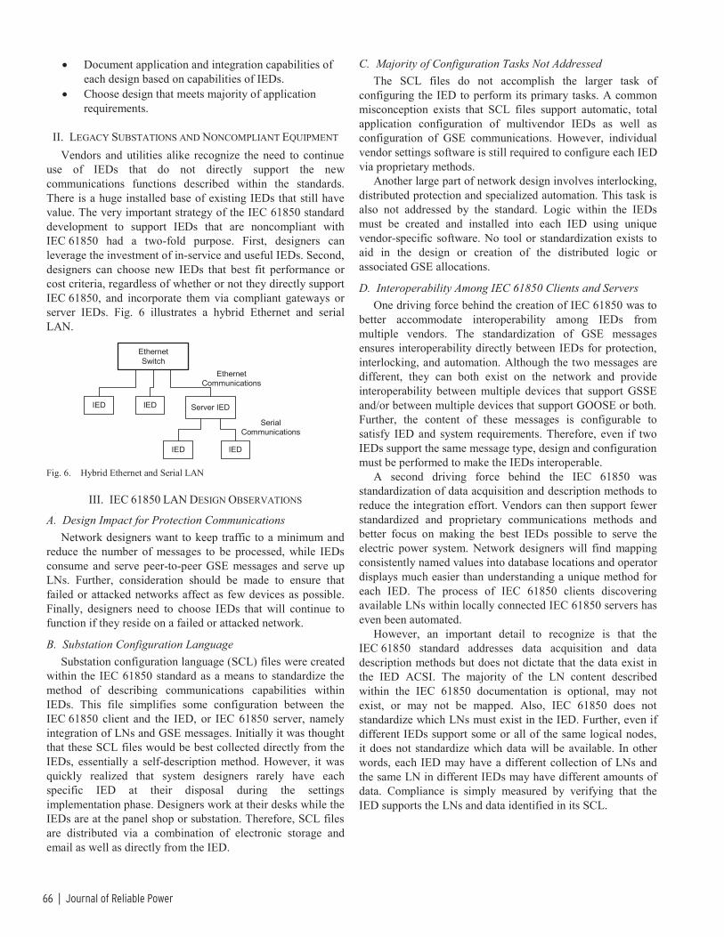
66 | Journal of Reliable Power
• Document application and integration capabilities of each design based on capabilities of IEDs.
• Choose design that meets majority of application requirements.
II. LEGACY SUBSTATIONS AND NONCOMPLIANT EQUIPMENT Vendors and utilities alike recognize the need to continue
use of IEDs that do not directly support the new communications functions described within the standards. There is a huge installed base of existing IEDs that still have value. The very important strategy of the IEC 61850 standard development to support IEDs that are noncompliant with IEC 61850 had a two-fold purpose. First, designers can leverage the investment of in-service and useful IEDs. Second, designers can choose new IEDs that best fit performance or cost criteria, regardless of whether or not they directly support IEC 61850, and incorporate them via compliant gateways or server IEDs. Fig. 6 illustrates a hybrid Ethernet and serial LAN.
EthernetSwitch
IED IED
IED
EthernetCommunications
SerialCommunications
Server IED
IED
Fig. 6. Hybrid Ethernet and Serial LAN
III. IEC 61850 LAN DESIGN OBSERVATIONS
A. Design Impact for Protection Communications Network designers want to keep traffic to a minimum and
reduce the number of messages to be processed, while IEDs consume and serve peer-to-peer GSE messages and serve up LNs. Further, consideration should be made to ensure that failed or attacked networks affect as few devices as possible. Finally, designers need to choose IEDs that will continue to function if they reside on a failed or attacked network.
B. Substation Configuration Language Substation configuration language (SCL) files were created
within the IEC 61850 standard as a means to standardize the method of describing communications capabilities within IEDs. This file simplifies some configuration between the IEC 61850 client and the IED, or IEC 61850 server, namely integration of LNs and GSE messages. Initially it was thought that these SCL files would be best collected directly from the IEDs, essentially a self-description method. However, it was quickly realized that system designers rarely have each specific IED at their disposal during the settings implementation phase. Designers work at their desks while the IEDs are at the panel shop or substation. Therefore, SCL files are distributed via a combination of electronic storage and email as well as directly from the IED.
C. Majority of Configuration Tasks Not Addressed The SCL files do not accomplish the larger task of
configuring the IED to perform its primary tasks. A common misconception exists that SCL files support automatic, total application configuration of multivendor IEDs as well as configuration of GSE communications. However, individual vendor settings software is still required to configure each IED via proprietary methods.
Another large part of network design involves interlocking, distributed protection and specialized automation. This task is also not addressed by the standard. Logic within the IEDs must be created and installed into each IED using unique vendor-specific software. No tool or standardization exists to aid in the design or creation of the distributed logic or associated GSE allocations.
D. Interoperability Among IEC 61850 Clients and Servers One driving force behind the creation of IEC 61850 was to
better accommodate interoperability among IEDs from multiple vendors. The standardization of GSE messages ensures interoperability directly between IEDs for protection, interlocking, and automation. Although the two messages are different, they can both exist on the network and provide interoperability between multiple devices that support GSSE and/or between multiple devices that support GOOSE or both. Further, the content of these messages is configurable to satisfy IED and system requirements. Therefore, even if two IEDs support the same message type, design and configuration must be performed to make the IEDs interoperable.
A second driving force behind the IEC 61850 was standardization of data acquisition and description methods to reduce the integration effort. Vendors can then support fewer standardized and proprietary communications methods and better focus on making the best IEDs possible to serve the electric power system. Network designers will find mapping consistently named values into database locations and operator displays much easier than understanding a unique method for each IED. The process of IEC 61850 clients discovering available LNs within locally connected IEC 61850 servers has even been automated.
However, an important detail to recognize is that the IEC 61850 standard addresses data acquisition and data description methods but does not dictate that the data exist in the IED ACSI. The majority of the LN content described within the IEC 61850 documentation is optional, may not exist, or may not be mapped. Also, IEC 61850 does not standardize which LNs must exist in the IED. Further, even if different IEDs support some or all of the same logical nodes, it does not standardize which data will be available. In other words, each IED may have a different collection of LNs and the same LN in different IEDs may have different amounts of data. Compliance is simply measured by verifying that the IED supports the LNs and data identified in its SCL.

IEC 61850: What You Need to Know About Functionality and Practical Implementation | 67
This obviously presents several problems for the network designer:
• It may become necessary to acquire the SCLs, or descriptions thereof, well in advance of selecting IEDs.
• Although each IED may create and provide a wealth of information, the network designer only has access to the subset that is mapped into the LNs.
• IEC 61850 implementation, and therefore available data, will most likely differ between IEDs.
An additional challenge is file transfer. IEC 61850 supports both FTP and MMS file transfer. These two methods standardize the mechanism used to transfer files of data between clients and servers such as settings, event records, and lists. However, IEC 61850 does not standardize the contents. Therefore, it is not required nor expected that these files be consistent or interoperable among different vendors or different products from one vendor.
E. Interchangeability Among IEC 61850 Clients and Servers The IEC 61850 standard was never intended to ensure
interchangeability of IEDs because of their inevitable unique inner workings and performance. However, it has become apparent that utilities would like to see interchangeability at the ACSI level so that they can freely choose between IEDs and vendors with respect to integration. The observations listed in the previous section, namely that the standard does not specify LNs or contents to be supported, make interchangeability difficult or impossible. Interchangeability or interoperability will definitely not be ensured by the standard. Utilities can bring this about only by describing in advance the required LNs and contents. This in turn ensures interchangeability and interoperability at the ACSI level for that customer, for a specific application, and for a specific group of IEDs.
IV. IEC 61850 LAN PRACTICAL IMPLEMENTATION OBSERVATIONS
A. Design Impact for Protection Communications Serially integrated LANs are fast, reliable, and reduce IED
message processing to a minimum because they physically isolate each IED from unnecessary traffic. Serially connected IEDs receive and process only messages sent directly to them.
In order to keep network message processing to an appropriate minimum and minimize the effect of failed or attacked networks, LANs are separated into connected yet separate segments. On these segments are the IEDs that serve a segment of the electric power system. These segments are designed to be as small as possible through physical or virtual means. For small stations, a single LAN is still appropriate, however, for larger systems LAN segment design has followed the natural progression toward serving a bay, or small collection of interrelated electric power system apparatus and functions. Because of their geographical proximity and logical association, integrated IEDs of a single bay are efficiently separated into physically isolated LAN segments. A segment is made up of a bay Ethernet switch and
collections of IEDs performing monitoring, control, protection, and local operator interface. At a minimum, this usually consists of a bay control unit (BCU), bay monitoring unit (BMU), bay protection units (BPUs), and a bay Ethernet switch. More sophisticated automation systems include additional equipment monitors, station battery monitoring systems, weather stations, controllers, LTCs, and other IEDs. Communication design within the bay is done based on the capabilities of the chosen IEDs. Fig. 7 illustrates multiple bay LAN segments.
Bay 2Ethernet Switch
BCU BMU BPU1 BPU2 BPU3 BPU4 BPU5
Bay 1Ethernet Switch
BCU BMU BPU1 BPU2
Bay 3Ethernet Switch
BMU BPU1 BCU
BPU2 EquipmentMonitor
IEC 61850
Serial
IEC 61850
IEC 61850
Fig. 7. Multiple Bay LAN Segments
The station LAN is visualized as a station control unit (SCU), a station Ethernet switch, and connections to each bay Ethernet switch. Additional station-level devices may include protocol translators, engineering workstations, and web-based operator interfaces. Communications design between the SCU and each bay is done based on the functional requirements of managing the power system apparatus associated with the bay. Fig. 8 illustrates the simplified logical view of a station comprised of the three bay LANs in Fig. 7. Each of the three bay designs in the example can function differently or the same within the substation LAN. In the example where all three function the same, it can be seen that three different IEC 61850 compliant designs serve the same data, yet have different quantities of IP addresses and GSE messages.
Bay 1Ethernet Switch
Four IP AddressesFour GSEs
Station EthernetSwitch
WebVisualization
SCU1 SCU2 EngineeringWorkstation
ProtocolConverter
Bay 2Ethernet Switch
Bay 3Ethernet Switch
Seven IP AddressesSeven GSEs
Three IP AddressesThree GSEs
Fig. 8. Logical View of Station LAN
B. Interoperability Among IEC 61850 Clients and Servers Design of integration at the IED level is standardized yet
still difficult to implement in practice. The IEC 61850 standard is most effective when used to design management of

68 | Journal of Reliable Power
power system apparatus and then choose combinations of IEDs to serve that purpose. Choosing a specific collection of IEDs first restricts the power system apparatus management to what the IEDs can support. Further, if the requirements change, they can only be accommodated if the IEDs are modified through a vendor product development and upgrade process.
The migration toward bay-oriented LAN segments, each with their own Ethernet switch, simplifies multivendor interoperability at the bay level. Bay LAN segments are designed to manage corresponding power system apparatus such as distribution feeders, transmission terminals, and transformers. The end user not only defines the functional, performance, reliability, availability, and physical requirements, but also the IEC 61850 communications requirements. Vendors then design bay networks of IEDs and communications to satisfy the requirements. The end user is free to choose among the bay designs based on their chosen acceptance criteria. It is also possible, and in some cases required, to permit communications methods other than IEC 61850 within a bay hybrid LAN. Data from these non-IEC 61850 communications methods are mapped to LNs and GSE via a gateway or server IED and then transferred to the station LAN. The station network design can integrate bays from several different vendors, each with a standardized IEC 61850 interface.
Since each different bay LAN design may have different types and quantities of IEDs, each bay LAN will obviously have different distributions of LNs and GSE messages. Therefore, LNs and GSE messages between the station server and each different bay LAN design, and between bay LANs, will be compliant with IEC 61850 and yet different. Referring to a previous example (Fig. 8), all of the LNs in a bay LAN with four multifunction IEDs (Bay 1) will have one of four IP addresses and there will be a minimum of four possible GSE messages. In a functionally equivalent bay with seven single-function IEDs (Bay 2), the same LNs will have one of seven different IP addresses and there will be a minimum of seven possible GSE messages.
Therefore, interchangeability at the bay level, rather than the IED level, will be much more useful and feasible.
C. Interoperability Between Existing Control Systems and Bay LANs
Utilities still use traditional telecontrol methods to send commands from the control center to the substation. Legacy SCADA protocols, DNP3, or IEC 60870 protocols need to be converted into IEC 61850 commanded control. This is presently done via an interface with the SCU that translates the SCADA command into an IEC 61850 message, which, in turn, is sent to the appropriate bay. Prior to passing on the command, the SCU checks the status of station level jurisdiction, permissions, tags, and interlocks to make sure the command is locally authorized. As with the other station data, the resulting status change is collected by the station server via an IEC 61850 LN and then translated into a SCADA message and sent to the control center.
Many utility designs require that remote control commands to the bay LAN be administered through the BCU rather than directly to the IED protecting the apparatus to be controlled. After receiving the commanded control from the SCU, the BCU performs a validation process, similar to the SCU, of bay-level jurisdiction, permissions, tags, and interlocks to make sure the command is locally authorized. The BCU then executes the command directly or passes a command message to an IED via IEC 61850, some other Ethernet protocol, or any number of other communications methods. This centralized bay LAN control authorization requires that the BCU communicate with the IEDs instead of, or in addition to, the IEDs communicating directly through the bay and station Ethernet switches to the SCU.
D. Interoperability and Interchangeability Between IEC 61850 Clients and Servers
Use of a global communications standard, like IEC 61850, provides the ability to predict how data will be moved and identified between clients and servers from any manufacturer. Again, the standard does not dictate which data will be present, but rather, if data do exist, how they will be moved and recognized. The most obvious benefit of this predictability is that the standard simplifies the integration effort in several ways.
• SCL file information uses standardized names and attributes to reduce the integration effort associated with creating a client database.
• Standardized SCL file format allows automated processing of portions of the client database.
• Integration between a client and multiple server IEDs with identical IEC 61850 interfaces will be the same and can be reused.
• Standardized LN nomenclature uses standardized names and attributes to reduce the integration effort associated with creating operator interfaces, logic, and control.
• Existing data within server IEDs, not previously mapped to LNs, can be easily exposed in compliance with IEC 61850 because IEC 61850 not only describes LNs but also describes standard methods to extend existing LNs to include new information and also how to create new LNs.
• When IEDs are modified, descriptions of their new IEC 61850 capabilities are available within a new SCL file.
V. VERIFICATION OF IED PERFORMANCE The final part of IEC 61850 is Part 10, Conformance
Testing. This part documents testing to verify that IEDs support the capabilities described within their SCL file. However, IEC 61850 LAN designers also need to be concerned about other IED performance characteristics not included in Part 10, such as the following:
• Time synchronization and time-stamp accuracy • Control reaction time • Operational and reliability criteria
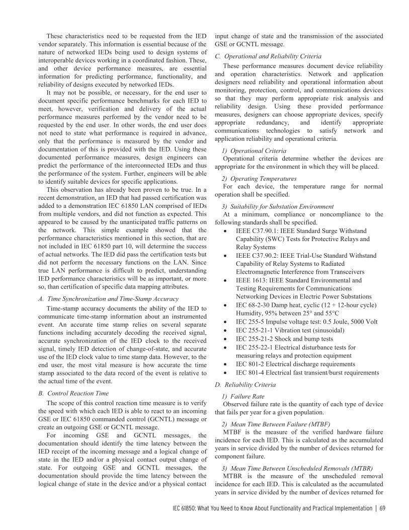
IEC 61850: What You Need to Know About Functionality and Practical Implementation | 69
These characteristics need to be requested from the IED vendor separately. This information is essential because of the nature of networked IEDs being used to design systems of interoperable devices working in a coordinated fashion. These, and other device performance measures, are essential information for predicting performance, functionality, and reliability of designs executed by networked IEDs.
It may not be possible, or necessary, for the end user to document specific performance benchmarks for each IED to meet, however, verification and delivery of the actual performance measures performed by the vendor need to be requested by the end user. In other words, the end user does not need to state what performance is required in advance, only that the performance is measured by the vendor and documentation of this is provided with the IED. Using these documented performance measures, design engineers can predict the performance of the interconnected IEDs and thus the performance of the system. Further, engineers will be able to identify suitable devices for specific applications.
This observation has already been proven to be true. In a recent demonstration, an IED that had passed certification was added to a demonstration IEC 61850 LAN comprised of IEDs from multiple vendors, and did not function as expected. This appeared to be caused by the unanticipated traffic patterns on the network. This simple example showed that the performance characteristics mentioned in this section, that are not included in IEC 61850 part 10, will determine the success of actual networks. The IED did pass the certification tests but did not perform the necessary functions on the LAN. Since true LAN performance is difficult to predict, understanding IED performance characteristics will be as important, or more so, than certification of specific data mapping attributes.
A. Time Synchronization and Time-Stamp Accuracy Time-stamp accuracy documents the ability of the IED to
communicate time-stamp information about an instrumented event. An accurate time stamp relies on several separate functions including accurately decoding the received signal, accurate synchronization of the IED clock to the received signal, timely IED detection of change-of-state, and accurate use of the IED clock value to time stamp data. However, to the end user, the most vital measure is how accurate the time stamp associated to the data record of the event is relative to the actual time of the event.
B. Control Reaction Time The scope of this control reaction time measure is to verify
the speed with which each IED is able to react to an incoming GSE or IEC 61850 commanded control (GCNTL) message or create an outgoing GSE or GCNTL message.
For incoming GSE and GCNTL messages, the documentation should identify the time latency between the IED receipt of the incoming message and a logical change of state in the IED and/or a physical contact output change of state. For outgoing GSE and GCNTL messages, the documentation should provide the time latency between the logical change of state in the device and/or a physical contact
input change of state and the transmission of the associated GSE or GCNTL message.
C. Operational and Reliability Criteria These performance measures document device reliability
and operation characteristics. Network and application designers need reliability and operational information about monitoring, protection, control, and communications devices so that they may perform appropriate risk analysis and reliability design. Using these provided performance measures, designers can choose appropriate devices, specify appropriate redundancy, and identify appropriate communications technologies to satisfy network and application reliability and operational criteria.
1) Operational Criteria Operational criteria determine whether the devices are
appropriate for the environment in which they will be placed.
2) Operating Temperatures For each device, the temperature range for normal
operation shall be specified.
3) Suitability for Substation Environment At a minimum, compliance or noncompliance to the
following standards shall be specified. • IEEE C37.90.1: IEEE Standard Surge Withstand
Capability (SWC) Tests for Protective Relays and Relay Systems
• IEEE C37.90.2: IEEE Trial-Use Standard Withstand Capability of Relay Systems to Radiated Electromagnetic Interference from Transceivers
• IEEE 1613: IEEE Standard Environmental and Testing Requirements for Communications Networking Devices in Electric Power Substations
• IEC 68-2-30 Damp heat, cyclic (12 + 12-hour cycle) Humidity, 95% between 25° and 55°C
• IEC 255-5 Impulse voltage test: 0.5 Joule, 5000 Volt • IEC 255-21-1 Vibration test (sinusoidal) • IEC 255-21-2 Shock and bump tests • IEC 255-22-1 Electrical disturbance tests for
measuring relays and protection equipment • IEC 801-2 Electrical discharge requirements • IEC 801-4 Electrical fast transient/burst requirements
D. Reliability Criteria
1) Failure Rate Observed failure rate is the quantity of each type of device
that fails per year for a given population.
2) Mean Time Between Failure (MTBF) MTBF is the measure of the verified hardware failure
incidence for each IED. This is calculated as the accumulated years in service divided by the number of devices returned for component failure.
3) Mean Time Between Unscheduled Removals (MTBR) MTBR is the measure of the unscheduled removal
incidence for each IED. This is calculated as the accumulated years in service divided by the number of devices returned for

70 | Journal of Reliable Power
confirmed component failure plus those returned with no problem found.
Reliability criteria are used to predict the performance of the resulting design and are used to perform the following:
• Identifying mission-critical components. • Verifying device and system reliability. • Assessing device and system risk. • Investigating accidents/incidents. • Evaluating design changes. • Displaying the causes and consequences of events. • Identifying common-cause failures. • Predicting quantity of device failures over time. • Predicting maintenance effort and cost over time.
VI. CONCLUSIONS
A. Design Impact for Protection Communications The standardization of GSE messages ensures
interoperability directly between IEDs for protection, interlocking, and automation. Although the two messages, GOOSE and GSSE, are different, they both coexist on the network and provide interoperability between multiple devices that support GSSE, and/or between multiple devices that support GOOSE, or both.
Bay LAN segments keep network message processing to an appropriate minimum and minimize the effect of failed or attacked networks.
B. Interoperability Among IEC 61850 Clients and Servers Designs created by defining strict IEC 61850 requirements
at the IED level unnecessarily restrict the choice of IEDs and or the available functionality of the bay LAN.
Serially integrated LANs are fast and reliable, and reduce IED message processing to a minimum because they physically isolate each IED from unnecessary traffic. Serial connections to IEDs within a bay Ethernet LAN create a hybrid LAN. This hybrid LAN allows the network designer to choose from all new and in-service IEDs including BCUs, BMUs, BPUs, equipment monitors, weather stations, controllers, LTCs, meters, and battery monitoring systems. Therefore, installed investments can be leveraged and a wider selection of IEDs can be used to create substation automation systems.
Communications among IEDs within a hybrid bay LAN can be performed using IEC 61850, other Ethernet protocols, or other direct communications methods. This allows access to relevant IED data that are not presently exposed as part of the IED-IEC 61850 interface.
The migration toward bay-oriented LAN segments, each with their own Ethernet switch, simplifies multivendor interoperability at the bay level. IEC 61850 communications requirements defined at the bay level, permit use of the data modeling within the standard to satisfy application requirements associated with power system apparatus management.
Bay level interoperability allows end users to choose from bay LAN designs from multiple vendors based on functional,
performance, reliability, availability, physical and communi-cations acceptance criteria. These bay designs may be functionally equivalent, but still have different quantities of IEDs, LN addresses, and GSE messages.
Although initial IEC 61850 designs have focused on performing protection and SCADA replacement, more sophisticated future substation automation designs will likely require that the BCU communicate with the other bay IEDs and provide a centralized and concentrated data store and processing environment.
Data access security requirements may require other modifications to LAN segment design.
Reliability concerns virtually dictate that BCUs should support redundant, separate, physical Ethernet connections.
C. Interoperability Between Existing Control Systems and Bay LANs
Centralized bay LAN control authorization requires that the BCU communicate with the BMU, BPUs, and other IEDs instead of, or in addition to, the IEDs communicating directly through the bay and station Ethernet switches to the SCU.
IEC 61850 was designed for use within the substation and for IED quantities associated with a substation. Current implementations require that IEC 61850 be converted to legacy telecontrol protocols for communications to the remote control center.
Presently, substation LAN traffic is high enough that LAN segmentation is necessary. Therefore, even when high-speed Ethernet connections between the remote control center and substation are possible, the remote control center may not be capable of managing the process burden of communications directly to each IED. SCUs or BCUs will need to act as single points of contact to communicate data and control.
D. Interoperability and Interchangeability Among IEC 61850 Clients and Servers
The IEC 61850 standard is most effective when used to design bay LANs and when combinations of IEDs are then chosen to serve that purpose.
If the end user provides detailed IEC 61850 communications requirements in advance, vendors can develop the necessary IEC 61850-IED interface. This implementation satisfies the end user until new data requirements are recognized. This implementation may not satisfy other end user requirements and may need modification for each situation.
Existing data within server IEDs that are not presently mapped to LNs can be exposed to the
IEC 61850 LAN when existing LNs are extended or new LNs created.
Standardized names and attributes enable standardized LN nomenclature to reduce the integration effort associated with creating operator interfaces, logic, and control. However, when one bay LAN is replaced with another containing different LN and GSE characteristics, the database, logic, and operator interfaces will need to be reconfigured. If the characteristics are the same, this integration effort can be reused.

IEC 61850: What You Need to Know About Functionality and Practical Implementation | 71
Some end users intend to require that it be possible to replace any IED within a bay LAN with another IED from any manufacturer. This is referred to as interchangeability. Replacement of one IED by another may affect the function of the coordinated system because of the different operating principles used by different IED vendors. However, a hybrid LAN is capable of supporting interchangeability with many different IEDs at the IEC 61850 communications interface level. Appropriate LN and GSE interfaces are created in the new IED or within server IEDs on the LAN.
E. Realities of Moving From Design to Implementation Communications traffic on actual substation Ethernet
LANs will not be limited to the handful of protocols within the IEC 61850 standard. Substation LANs will also support traffic for web server applications in the IEDs and HMIs, nonstandard IED protocols such as vendor specific, Modbus IP, and DNP IP, email; Legacy SCADA protocols such as IEC 60870; vendor-specific IED configuration and diagnostic applications; network analyzer configuration and diagnostic applications; telephone and camera applications, etc.
The present certification method accomplishes only part of the necessary task to ensure a successful installation. The network designer must make sure that the IED supports the necessary data requirements and that the IED performance characteristics mesh with the other components to create a successful network. Finally, it seems clear that a flexible data mapping technology at the IED and bay level will make the physical application of an IEC 61850 network much easier to accomplish.
VII. REFERENCE [1] E. Udren, S. Kunsman, and D. Dolezilek, “Significant Substation
Communication Standardization Developments,” Proceedings of the 2nd Annual Western Power Delivery Automation Conference, Spokane, WA, April 4-6, 2000.
VIII. BIOGRAPHY David J. Dolezilek received his BSEE from Montana State University in 1987. He worked as project engineer and manager for the Montana Power Company and the California Department of Water Resources prior to becoming self-employed as a control system consultant. He joined Schweitzer Engineering Laboratories, Inc. in 1996 as their first system integration engineer. Dolezilek became the Director for North American Sales in 1997, R&D Engineering Manager for Automation and Communications Engineering in 1998, and Automation Technology Manager in 2000, to research and design automated systems. In 2003, Dolezilek became Sales and Customer Service Technology Director. He is the author of numerous technical papers and continues to research and write about innovative design and implementation affecting our industry. Dolezilek participates in numerous working groups and technical committees. He is a member of the IEEE, the IEEE Reliability Society, Cigre WG 35.16, and the International Electrotechnical Commission (IEC) Technical Committee 57 tasked with global standardization of communication networks and systems in substations. He holds US Patent number 6,655,835, titled “Setting Free Resistive Temperature Device (RTD) Measuring Module.”
© 2004, 2005 by Schweitzer Engineering Laboratories, Inc. All rights reserved.
20050304 • TP6170-01

72 | Journal of Reliable Power
IEC 61850 – What It Can and Cannot Offer to Traditional Protection Schemes
Daqing Hou and Dave Dolezilek, Schweitzer Engineering Laboratories, Inc.
Abstract—As the latest standard that is quickly gaining popularity in power substation automation, IEC 61850 offers self-descriptive object data models, standardized configurability with Substation Configuration Language (SCL), the promise of interoperations among intelligent electronic devices (IEDs) from different manufacturers, and lower integration installation costs. The IEC 61850 standard initially focused on communications between IEDs within a single power substation. However, the working groups of IEC Technical Committee TC57 are prepar-ing IEC 61850 for communications between substations and between substations and control centers. Most existing papers regarding IEC 61850 concentrate on the standard, communica-tion, and automation.
In this paper, from a protection engineer’s point of view, we examine what the standard can and cannot offer to traditional protection schemes that require communications assistance. These protection schemes include fast bus tripping, breaker failure, directional comparison blocking (DCB), permissive overreaching transfer trip (POTT), and others. We review the Generic Object-Oriented Substation Event (GOOSE) control mode mechanism of the standard: its generation, mapping, com-munication over local-area and wide-area networks, and timing aspects. With this knowledge, we compare the use of GOOSE messages with traditional protection schemes in terms of feasibility, speed, and dependability.
I. INTRODUCTION Modern microprocessor relays are no longer merely
protection devices for power apparatus but have evolved to perform many other functions that facilitate effective power system operation. Contemporary microprocessor relays routinely include metering, protection, automation, control, digital fault recording (DFR), and reporting. Because of this, it is now more accurate to refer to these microprocessor devices as intelligent electronic devices (IEDs). As IEDs replace old electromechanical relays and prevail in today’s power substations, the amount of data available from substations increases exponentially.
Early supervisory control and data acquisition (SCADA) systems integrated information from generation stations and substations through remote terminal units (RTUs) to provide operators with system-wide knowledge to plan and operate the power system. These RTUs and SCADA systems typically used additional transducers and contacts that were separate from the protection systems to acquire system information. The information update was also slow for these systems, on the order of several seconds to minutes. Now the substation’s IEDs are performing more system automation and control functions. Almost all the information required by system operators (and more) is available from these IEDs once they are networked together. These substation IED networks reduce
or eliminate additional transducers, input and output contacts, and even RTUs. They are also able to provide data at a much faster speed.
To accommodate new, increasingly popular IED network functions, today’s substation communications infrastructure is also experiencing a dramatic change. Substation IED network communications are migrating to Ethernet. Previous substa-tion integration systems were often based on IED networks built using EIA-232 point-to-point and EIA-485 multidrop communications ports within the IEDs. These ports communi-cate at a speed equal to or less than 38.4 kilobits per second (Kbps). The information exchanges are carried out using such register/address-based protocols as DNP3 and Modbus®. With the new IEC 61850 standard and the popularity of the Ethernet networks, the entire picture of substation communications is changing.
Based on the Utility Communications Architecture (UCA), the IEC 61850 communications standard harmonized with the early UCA protocols and eventually developed into a massive, ten-part international standard. Today, the IEC 61850 standard is gaining popularity in utilities. Many substation integration and automation projects are built demonstrating the benefits of the standard [1].
In addition to many client-server substation integration, automation, and control functions, the IEC 61850 standard includes two real-time, peer-to-peer communications methods that are particularly useful to protection engineers: Generic Substation Event (GSE) messaging and Sampled Values (SV) messaging. The two types of GSE messages, Generic Object-Oriented Substation Event (GOOSE) and Generic Substation State Event (GSSE), can coexist but are not compatible. GSSE is an older, binary-only message type, and all new systems use the more flexible GOOSE, which conveys both binary and analog data. These peer-to-peer communications mechanisms allow protection engineers to revolutionize traditional protec-tion and control schemes, reducing the costs of system design, installation, commissioning, operating, and maintenance, and at the same time, increase the reliability of the system. Inno-vative research is underway developing methods of protection via SV messaging distributed across switched Ethernet net-works. This is yet another important IEC 61850 messaging protocol that will ensure multivendor interoperability when implemented according to the standard.
With the new IEC 61850 standard, communications standards and protocols are no longer only for substation integration engineers. To effectively use the available features for protection, protection engineers must understand the com-munications and information systems. Protection engineers

IEC 61850—What It Can and Cannot Offer to Traditional Protection Schemes | 73
need to understand the mechanisms involved in a GOOSE message: creation, publication, and subscription, as well as the parameters of the communications networks that transmit the messages. Using this information, protection engineers can understand and influence the performance of GOOSE mes-sages and therefore the speed, jitter, security, and dependa-bility that affect the protection schemes. Then they can accurately specify the substation local-area networks (LANs) or intersubstation wide-area networks (WANs) to guarantee the reliable operation of their protection schemes.
In this paper, we concentrate on the IEC 61850 GOOSE messages that protection engineers use to implement tradi-tional protection schemes. We also examine Ethernet commu-nications networks and the elements that impact GOOSE performance.
SV peer-to-peer messaging is used to pass digitized transducer signals from switchyards to IEDs inside substa-tions. SV messaging is not directly related to traditional communications-aided protection scheme implementations and therefore is out of the scope of this paper. However, like GSE, IEC 61850-compliant SV messages are multicast, so data measured at one location are sent to any number of subscribers through the Ethernet network. Many new, exciting design possibilities are enabled by using multicast messages instead of point-to-point messages. Expect future research and papers to explore how to use these messages for new protection schemes.
Finally, the last part of this paper discusses protection schemes that can benefit from the GOOSE communications method.
II. IEC 61850 AND GOOSE MESSAGES In this section, we briefly introduce the IEC 61850
standard, its main features, and its benefits. We then introduce details of peer-to-peer GOOSE communications and discuss their protection applications.
A. IEC 61850 As microprocessor relays integrate more functions such as
metering, protection, and control into one physical device, many communications protocols have been developed to integrate virtually thousands of pieces of information from each IED. These protocols include independent standards such as IEC 60870 and DNP3, managed by a committee (users group) funded by a collection of vendors and users that organize enhancements and testing. They also include many proprietary protocols such as Modbus Plus®, SEL MIRRORED BITS® communications, and others that were invented by a specific manufacturer and are vendor independent but for
which enhancements and testing are performed by the vendor of the protocol. Many protocols of both varieties can coexist on an IED network to collectively serve many different functions. However, complex combinations of protocols make designing an overall substation automation system (SAS) to integrate information from devices of different manufacturers a daunting task. Especially important is the task of integrating or isolating protection communications, which is often per-formed by the protection engineer and not a network commu-nications architect. Protocols like SEL MIRRORED BITS communications work independently of the shared IED communications network on point-to-point connections and therefore cannot adversely influence the function or performance of the SAS communications network. However, protocols designed to coexist on the SAS network, like GOOSE and SV, pose additional challenges. The protection engineer needs to not only design a safe and reliable protection communications strategy but must also take care not to influence the other SAS communications or let the other SAS communications interfere with protection messages.
Another issue is time synchronization. Up until now, IEC 61850 has been predominantly used to perform simple SAS functions like SCADA. The IEC 61850 communications standard is constantly evolving to include new technology and practices to serve additional functions as they become more popular. So, although the use of GPS-based time synchroni-zation is mentioned in the standard, much detail is included about using the SNTP (Simple Network Time Protocol) method. However, the existing SNTP method can provide at best 1-millisecond accuracy and only on carefully designed Ethernet networks. The time stamp assigned to data changes has microsecond resolution but only 1-millisecond accuracy. This is not acceptable for protection and most other applications.
Presently, protection class time-stamp accuracy is only available via GPS methods like IRIG-B. A separate IRIG-B network has the added advantage of maintaining time synchronization during an Ethernet network failure.
IEEE is working on a profile of the IEEE 1588 time-synchronization method, which will provide greater accuracy over Ethernet networks by capturing the time each message is received. This information, in combination with the time-synchronization information in the message, is used to accurately time-synchronize over nondeterministic Ethernet. Vendor proprietary modifications of SNTP methods could work similarly but are not recommended because they are not standardized or widely available.
Protection engineers use IRIG-B time-synchronization methods today and are watching the evolution of IEEE 1588.

74 | Journal of Reliable Power
The IEC 61850 standard includes a model of a substation communications interface system, as shown in Fig. 1 [2]. It separates the substation communications into process level, bay level, and substation level.
Fig. 1. Interface model of a substation automation system as depicted in IEC 61850-1
One of the main objectives of the IEC 61850 communications standard is to provide a set of standard model structures for data and rules defining how to exchange these data. IEDs from different manufacturers that comply with these model definitions can then understand, communicate, and interact with each other [2]. The standard achieves this interoperability by “abstracting” the data and service models in IEC 61850-7-x. The concept “abstract” means that these models are defined independently from underlying communi-cations systems or protocols. IEC 61850-7-4 identifies the smallest possible function pieces that need to exchange infor-mation and refers to these functions as logical nodes (LNs). Each LN consists of data sets, data attributes, and associated communications services. The common data classes (CDC) specified in IEC 61850-7-3 model these data sets and data attributes with common formats and structures. The Abstract Communications Service Interface (ACSI) specified in IEC 61850-7-2 models communications services with defined behaviors and responses.
The abstract models can be mapped to any set of communications protocols. As long as two IEDs use the specified object models and the same mapping protocols, they are able to understand each other and exchange information. IEC 61850-8 specifies the mapping with a set of prevailing communications protocols that are capable of supporting the complexity of the models. These protocols include Manufacturing Message Specification (MMS), GOOSE, SNTP, and SV. The Ethernet technologies (referred to as Ethertypes) TCP/IP and UPD are standards and transport MMS and SNTP, respectively. Two new Ethertypes, designed and used specifically for IEC 61850, transport GOOSE and SV. The message types and their associated performance classes are introduced in the next subsection.
To configure IEC 61850-based systems, the standard specifies a Substation Configuration Language (SCL) that is based on Extensible Markup Language (XML). The various SCL-based configuration files include:
• System specification description (SSD) file that outlines a substation automation project, optionally including system one-line diagrams.
• IED capability description (ICD) file that describes the available functions (LNs) and services available from an IED.
• Substation configuration description (SCD) file that describes the relationship among the IEDs in the substation automation project and their information exchange structures.
• Configured IED description (CID) file that is the final file to download into an IED to enable its configured functions.
There are many benefits that can be realized using the IEC 61850 standard in a substation integration project. The main advantages include:
• Interoperability among IEDs from different vendors. • Simplified system design and commissioning using
the SCL-based configuration tools and self-describing features.
• Reduced installation cost by replacing wired information exchanges among IEDs with GOOSE messages.
• Easy expansion to accommodate future system growth.
On the other hand, the IEC 61850 standard blurs the traditional boundaries of responsibility among many utility departments, including metering, protection, automation, dispatch control, SCADA, and communications. As seen in all projects to date, future substation design, installation, com-missioning, operation, and maintenance will require the different divisions of a utility to work together to enjoy the entire benefits offered from the standard.
Finally, the true benefits of using the standard are only realized if vendors deploy the technology based on the definitions in the standard. The successful, purpose-built protocols, including SEL MIRRORED BITS communications, are deployed as nonroutable protocols over point-to-point links. As such they are very successful, deployed by several different vendors and interoperable, but they are not part of an international standard. The simplicity and purpose-built nature of these connections provides cost savings in design, installa-tion, commissioning, wire reduction, and testing as substations are modernized to digital communications. These savings are even greater than those realized by IEC 61850 methods, but they are not adopted by the large international multivendor community.
Proprietary implementation of the IEC 61850 standard messages or data flow techniques yields noninteroperable devices. Further, if not clearly identified as single-vendor, custom, and noninteroperable, this technology may cause customer confusion and frustration.

IEC 61850—What It Can and Cannot Offer to Traditional Protection Schemes | 75
B. IEC 61850 GOOSE Messaging Two of the most useful features of the IEC 61850
communications standard are the peer-to-peer GOOSE and GSSE messages. GSSE is also known as UCA GOOSE. The difference is that while the IEC GOOSE message may include many data types like analog, binary, and integer values, the GSSE message is limited to support only a fixed structure of binary event status data.
GOOSE and GSSE messages use multicast services that allow simultaneous delivery of the same substation event message to multiple IEDs.
The GOOSE message can serve several different applica-tions that each have different performance requirements. IEC 61850 classifies application types based on how fast the messages are required to be transmitted among networked IEDs [2]. The standard also specifies the performance of each type of application, documented as time duration of message transmission. Table I lists the message types.
TABLE I IEC 61850 MESSAGE TYPES AND PERFORMANCES
Type Applications Performance Class
Requirements (Transmission
Time)
1A Fast Messages
(Trip)
P1 10 ms
P2/P3 3 ms
1B Fast Messages
(Other)
P1 100 ms
P2/P3 20 ms
2 Medium Speed 100 ms
3 Low Speed 500 ms
4 Raw Data P1 10 ms
P2/P3 3 ms
5 File Transfer ≥1000 ms
6 Time Synchronization (Accuracy)
Type 4 messages are also used for metering and power quality and meet the respective performance classes M1, M2, and M3. The Type 6 message performance requirement is dictated by the required accuracy of time synchronization. The IEC 61850 communications standard requires that the time-synchronization accuracy be ten times faster than the required time-stamp accuracy. The message speed needs to be fast and accurate enough to synchronize IED clocks to 0.1-millisecond accuracy so that IED data time stamps can be accurate to 1 millisecond. These performance classes and requirements are out of the scope of this paper.
The transmission time specified in the requirements column in Table I is the maximum time allowed for a data exchange through a communications system. This term is vague but is usefully defined as the time duration between the action of communicating a value from the logic processing of one device to the logic processing within a second device as part of an application. This transmission time is clearly illustrated in Fig. 2 (from IEC 61850-5). Time ta is the time
duration of the communications processor algorithm within the physical device (or IED) PD1. This algorithm uses data received from the input and logic processing of PD1 as the contents of messages that it creates and publishes. Detection, processing, and time-stamping of a physical contact input change of state in PD1 is a typical function represented by f1. Time tb represents the actual transit time of the message across the network between the IEDs. Time tc is the time duration of the communications processor algorithm within PD2, which receives and processes the message from PD1. The function f2 in PD2 represents processing the message contents received from PD1, subsequent closure of a physical output contact, and associated time stamp.
The time duration to create and deliver messages between IEDs via a protocol is the message transmission time represented by ttransmission = ta + tb + tc. The time duration to publish information in PD1, deliver it via a protocol message, and act on it in PD2 is the information transfer time represented by ttransfer = ttransmission + tf2. This information transfer time duration is the time truly useful to the design engineer because it represents actually performing an action as part of a communications-aided automation or protection scheme. Transfer time, ttransfer, is easily measured as the time difference between the time-stamped sequential events records (SERs) in IEDs with synchronized clocks. The time difference between the SER of detection of the input contact in PD1 and the SER of the output contact closure in PD2 represents ttransfer = ttransmission + tf2.
Therefore, ttransmission, though not measurable, is easily calculated as ttransfer – tf2 (or ttransfer – the IED processing cycle duration).
Fig. 2. Definition of transmission time (from IEC 61850-5)
GOOSE messages are Type 1 or 1A fast messages. This type of message typically uses simple binary data intended for protection and fast controls and, in some instances, analog values. These GOOSE messages are mapped directly to the previously mentioned Ethertypes to optimize their decoding and to reduce overall transmission time. Due to the multicast nature of the Ethertype and the design of Ethernet, the messages are connectionless. It is unknown what IEDs will receive the message, delivery is not guaranteed, and there is no acknowledgement from IEDs that do receive the GOOSE message. Due to the lack of an addressing layer (which was removed in order to optimize the multicast function of sending
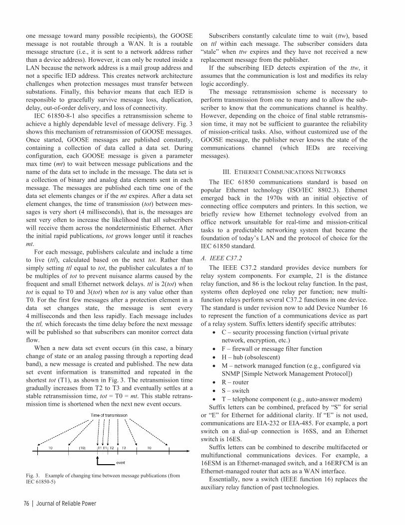
76 | Journal of Reliable Power
one message toward many possible recipients), the GOOSE message is not routable through a WAN. It is a routable message structure (i.e., it is sent to a network address rather than a device address). However, it can only be routed inside a LAN because the network address is a mail group address and not a specific IED address. This creates network architecture challenges when protection messages must transfer between substations. Finally, this behavior means that each IED is responsible to gracefully survive message loss, duplication, delay, out-of-order delivery, and loss of connectivity.
IEC 61850-8-1 also specifies a retransmission scheme to achieve a highly dependable level of message delivery. Fig. 3 shows this mechanism of retransmission of GOOSE messages. Once started, GOOSE messages are published constantly, containing a collection of data called a data set. During configuration, each GOOSE message is given a parameter max time (mt) to wait between message publications and the name of the data set to include in the message. The data set is a collection of binary and analog data elements sent in each message. The messages are published each time one of the data set elements changes or if the mt expires. After a data set element changes, the time of transmission (tot) between mes-sages is very short (4 milliseconds), that is, the messages are sent very often to increase the likelihood that all subscribers will receive them across the nondeterministic Ethernet. After the initial rapid publications, tot grows longer until it reaches mt.
For each message, publishers calculate and include a time to live (ttl), calculated based on the next tot. Rather than simply setting ttl equal to tot, the publisher calculates a ttl to be multiples of tot to prevent nuisance alarms caused by the frequent and small Ethernet network delays. ttl is 2(tot) when tot is equal to T0 and 3(tot) when tot is any value other than T0. For the first few messages after a protection element in a data set changes state, the message is sent every 4 milliseconds and then less rapidly. Each message includes the ttl, which forecasts the time delay before the next message will be published so that subscribers can monitor correct data flow.
When a new data set event occurs (in this case, a binary change of state or an analog passing through a reporting dead band), a new message is created and published. The new data set event information is transmitted and repeated in the shortest tot (T1), as shown in Fig. 3. The retransmission time gradually increases from T2 to T3 and eventually settles at a stable retransmission time, tot = T0 = mt. This stable retrans-mission time is shortened when the next new event occurs.
Fig. 3. Example of changing time between message publications (from IEC 61850-5)
Subscribers constantly calculate time to wait (ttw), based on ttl within each message. The subscriber considers data “stale” when ttw expires and they have not received a new replacement message from the publisher.
If the subscribing IED detects expiration of the ttw, it assumes that the communication is lost and modifies its relay logic accordingly.
The message retransmission scheme is necessary to perform transmission from one to many and to allow the sub-scriber to know that the communications channel is healthy. However, depending on the choice of final stable retransmis-sion time, it may not be sufficient to guarantee the reliability of mission-critical tasks. Also, without customized use of the GOOSE message, the publisher never knows the state of the communications channel (which IEDs are receiving messages).
III. ETHERNET COMMUNICATIONS NETWORKS The IEC 61850 communications standard is based on
popular Ethernet technology (ISO/IEC 8802.3). Ethernet emerged back in the 1970s with an initial objective of connecting office computers and printers. In this section, we briefly review how Ethernet technology evolved from an office network unsuitable for real-time and mission-critical tasks to a predictable networking system that became the foundation of today’s LAN and the protocol of choice for the IEC 61850 standard.
A. IEEE C37.2 The IEEE C37.2 standard provides device numbers for
relay system components. For example, 21 is the distance relay function, and 86 is the lockout relay function. In the past, systems often deployed one relay per function; new multi-function relays perform several C37.2 functions in one device. The standard is under revision now to add Device Number 16 to represent the function of a communications device as part of a relay system. Suffix letters identify specific attributes:
• C – security processing function (virtual private network, encryption, etc.)
• F – firewall or message filter function • H – hub (obsolescent) • M – network managed function (e.g., configured via
SNMP [Simple Network Management Protocol]) • R – router • S – switch • T – telephone component (e.g., auto-answer modem)
Suffix letters can be combined, prefaced by “S” for serial or “E” for Ethernet for additional clarity. If “E” is not used, communications are EIA-232 or EIA-485. For example, a port switch on a dial-up connection is 16SS, and an Ethernet switch is 16ES.
Suffix letters can be combined to describe multifaceted or multifunctional communications devices. For example, a 16ESM is an Ethernet-managed switch, and a 16ERFCM is an Ethernet-managed router that acts as a WAN interface.
Essentially, now a switch (IEEE function 16) replaces the auxiliary relay function of past technologies.

IEC 61850—What It Can and Cannot Offer to Traditional Protection Schemes | 77
B. IEEE 1613 Environmental Hardening IEEE 1613 was developed to help customers understand
and request communications devices designed to withstand the same rigors as protective relays, especially for those devices installed among, and moving data between, relays for communications-aided protection schemes. Early modems and radios did not meet these standards; new devices are now available as a consequence of the standard. The same is be-coming true for Ethernet devices that were initially developed for the office environment.
IEEE 1613 specifies that a communications device meets the following:
• Operates at least from –20 to +55 degrees C, up to –40 to +85 degrees C, with high humidity.
• No cooling fans. • Operates from station battery dc voltages with ripple. • Dielectric tests 2 kV/500 V. • 5 kV impulse tests for insulation barriers. • Oscillatory surge withstand capability (SWC) test,
2.5 kV 1 MHz decaying wave. • Fast transient SWC test, 4 kV for 50 ns. • Radio frequency interference (RFI) susceptibility test,
35 V/m from 80 MHz to 1 GHz. • Electrostatic discharge (ESD) tests as for relays,
IEEE C37.90.3. • Vibration and physical shock tests as in IEEE C37.1. • Class 1 – temporary data errors; Class 2 – no data
errors during disturbances (for relaying).
C. CSMA/CD CSMA/CD stands for carrier sense multiple access with
collision detection. In an original Ethernet LAN, many com-puters, relays, or other devices, each with a network interface card (NIC), connect together to one physical medium, such as a coaxial cable. When a relay needs to respond to a request or send unsolicited data on the network, it will detect if there is data transmission already on the media. If the relay does not sense any carrier, it then starts to transmit data. Computer and relay networks consist of multiple devices attached to the same media and doing the same thing. Therefore, it is un-avoidable that two or more devices may try to send data on the same media at the same time. Collision occurs. In such a situation, each device detects the collision, stops transmitting, waits a random time to reduce the likelihood of causing a second collision, and starts retransmission. This process is CSMA/CD.
When the number of computers or IEDs connected to the same communications segment increases, the likelihood of data collisions increases exponentially. As well as introducing prolonged data transmission delays, frequent data collisions may also drop data packets and cause unpredictable network behaviors. Modern switched Ethernet uses separate, new communications IEDs, Ethernet switches, to reduce or eliminate data collisions.
An Ethernet switch is an IED itself and has an operating system and firmware, multiple required settings, power supply, and multiple Ethernet ports. Each port connects to one
computer or IED and forms a small network segment. This configuration eliminates the shared medium among multiple devices. With the use of twisted pairs and fiber cables that separate the transmitted and received traffic, modern switched Ethernet LANs create a truly full-duplex and collision-free communications environment.
An Ethernet switch keeps a list of media access control (MAC) addresses of each device it connects to. It talks to all devices connected to it simultaneously. When receiving a message from a port, the switch examines the destination MAC address of the message and forwards it only to the port with a device that matches the address. This switching mechanism in today’s Ethernet speeds up the data transmis-sion and makes 100 Mbps networks quite standard and gigabit networks possible. This method works for client-server traffic such as SCADA poll and response using MMS; however, it does not work for GOOSE. It was described previously that the GOOSE message was modified to behave in a multicast mode without knowledge of the destination MAC addresses. Therefore, GOOSE messages are published to a group multicast address, which goes to every port.
An Ethernet switch processes every message received or transmitted by each port. It takes time for switches to process messages, and this introduces a short but unavoidable switch processing latency delay. If a switch cannot process and forward all the messages it receives, a backlog occurs. A message will wait in a transmitting memory queue for its turn to be sent out. If this occurs, there is a switch queue latency in addition to the switch processing latency. A message may need to go through several switches in a network to reach its destination. The communications system transfer time t, shown in Fig. 2, will be the sum of all switch delays in a message path in the worst network configuration scenarios. When designed with knowledge and care, the likelihood of a switch queue delay is minimized but not eliminated.
D. IEEE 801.2Q – Priority Tagging/VLAN GOOSE is an example of an Ethernet multicast/broadcast
message. One device sends out this message intended for a group of devices on the network in the multicast case and for every device on the network in the broadcast case. The IEC 61850 GOOSE messages are specified as multicast mes-sages. When an IED receives a GOOSE message, it has to decode the message and see if it has previously been configured to subscribe to and receive each message. Multicast/broadcast messages on Ethernet increase the network traffic. When a switch receives such a message, it forwards it on to all the ports except the one from which it received the message. Large numbers of broadcast messages quickly fill the available network bandwidth. One of the tech-niques to alleviate the network burden of multicast/broadcast messages is the virtual local-area network (VLAN). IEEE extended the Ethernet Standard 802.1 with the designator Q for message quality, which includes extensions for optional VLAN and message priority information. IEEE 802.1Q VLAN divides a physically connected network into several virtual LANs, as shown in Fig. 4. VLANs originated from a

78 | Journal of Reliable Power
need to segregate network traffic from different departments inside one enterprise. While keeping the sensitive information private, VLAN techniques restrict traffic flow of multicast/broadcast messages to a single individual VLAN and therefore the devices within it.
Fig. 4. Switched Ethernet and VLAN configuration
Another technique to reduce network congestion caused by multicast/broadcast messages is to use priority tagging per IEEE 802.1P. Fig. 5 shows the VLAN/priority tag in an Ethernet frame. When there is a transmission backlog in a switch, the switch examines the user priority part of the tag and transmits frames with a higher priority first. The IEC 61850-8-1 standard specifies that default GOOSE messages should have a priority level of 4. However, network designers and protection engineers can choose any value between 0 and 7 to separate the GOOSE messages by order of
importance. It is important to know, however, that though relays support eight unique priorities, most switches do not. Care must be taken to understand and set relays and the switch, acting as an auxiliary in a protection scheme, to use these parameters correctly.
E. Network Redundancy In order to achieve high dependability, protection for high-
voltage lines and equipment normally requires a redundant system: primary and backup protection (e.g., a current differential relay for the primary protection and permissive overreaching transfer trip with a residual overcurrent as the backup protection for a transmission line). It would not be complete to discuss Ethernet systems used for real-time protection and control without mentioning the redundancy requirement.
Substation hardening requirements specified in the IEEE 1613-2003 standard provide methods to best choose the network equipment suitable for the harsh substation environ-ment. A looped network configuration or multiple paths between two points in a network provide redundancy to Ethernet LAN.
The Rapid Spanning Tree Protocol (RSTP) in a switch manages multiple communications paths and reconfigures the system topology in case of a physical path failure, such as a cut cable, failed port, or loose connection. This type of redundancy will not prevent a network outage if a switch fails or is out for maintenance or network expansion.
Fig. 5. Ethernet VLAN and priority tag

IEC 61850—What It Can and Cannot Offer to Traditional Protection Schemes | 79
Completely separate and redundant LANs that eliminate the single point of failure of a switch are also possible via many different configurations. One such configuration that provides total redundancy, two identical networks in place for mission-critical protection and control, is shown in Fig. 6 [3]. IEDs often have two Ethernet ports and a failover mechanism, that is, if one port fails, the IED automatically switches to use the backup port. The newest generation of IEDs have dual primary ports that are simultaneously connected to two differ-ent LANs without failover. This dual-port configuration is a perfect setup for two redundant communications networks. The two networks can be interconnected to mutually check the network health and share some network traffic in case of a partial failure of one network.
Fig. 6. Fully redundant LAN system for protection and control [3]
IV. IEC 61850 APPLICATION IN PROTECTION AND CONTROL Ever since the first microprocessor distance relay with a
fault locator appeared in early 1980s, people have gone through a period of reservations before accepting the new technology. With their advantages of integrating measure-ments, protection, automation, and control, performing contin-uous self-tests, and providing abundant information for system planning, operating, and maintenance, microprocessor relays or IEDs are enjoying wide application at all levels of power substations. In addition to traditional protection theories and applications, protection engineers have learned such new terms as data rate, MIRRORED BITS communications, and protocols that are related to microprocessor devices. With the new ingredients of IEC 61850 targeted to protection and real-time controls, protection engineers will once again have to understand more computer and communications network terms in order to gain the full benefit of the standard.
In this section, we group traditional protection schemes into two categories according to their communications re-quirements in terms of distance (within a substation or inter-substation) and data volume (single bit [binary] or continuous analog data). We discuss how the present IEC 61850 standard and its future extension will accomplish or improve traditional protection schemes.
A. Protection Schemes That Require Inter-IED Message Exchange Within a Substation
The following subsections describe some protection and control schemes that require information exchange between IEDs within a substation. These are typical applications where the GOOSE protection and control messages replace the hard wires and provide the same communication through an Ethernet LAN.
1) Fast Bus Tripping The fast bus tripping scheme typically applies to radial
distribution systems to achieve a clearance time for bus faults that is close to a bus differential scheme. This scheme is also referred to as reverse interlocking.
Fig. 7 shows the arrangement of a fast bus tripping scheme. The bus IED for the bus high-side breaker communicates with feeder IEDs about the location of a fault. If a fault occurs on a feeder, one of the feeder IEDs will detect the fault and issue a signal to block the fast tripping element in the bus IED. Otherwise, if a fault occurs on the bus, no feeder IEDs see the fault and block the bus IED, and the bus IED trips the bus using the fast overcurrent elements. A traditional fast bus scheme uses the IED contact input and output to communicate the fault information.
Bus IED
Fdr IED1
Fdr IED2
Fdr IED3
Fig. 7. Fast bus tripping scheme for distribution substation with radial feeders
2) Reclosing Control Modern IEDs typically incorporate both protection and
control functions like breaker reclosing. Most IEDs have sophisticated control schemes for two breakers to be used in the breaker-and-a-half and ring bus arrangements. Neverthe-less, many utilities use a dedicated IED to perform reclosing, breaker failure protection, and other functions for a specific breaker bay. In this situation, the trip signal of the protection IED initiates the reclosing IED through a hard-wire connection.

80 | Journal of Reliable Power
3) Breaker Failure Protection Local breaker failure backup protection is common for
high-voltage applications. As in the case of reclosing control, today’s IEDs typically have breaker failure protection built in, in addition to complete protection functions. When the IED issues a trip, it starts a timer and monitors the breaker current. If the current does not go away in a preset time, the IED issues a retrip or trips the adjacent breakers to isolate the faulted one. However, as in the case of the reclosing control, if a user wants to treat the breaker as a bay and perform the bay controls and protection, a dedicated IED can be used for breaker failure protection. The dedicated IED could monitor additional breaker conditions such as the gas pressure and the ambient temperature for a point-on-wave control purpose. The breaker failure initiation signal is passed from the protection IED to the breaker failure IED, using contact inputs and outputs and hard wires.
4) IEC 61850 GOOSE Applications Within a Substation The IEC 61850 standard was designed initially for com-
munications inside a substation. The traditional application schemes such as those outlined above are perfect applications for IEC 61850 GOOSE to replace wired communications channels and reduce engineering design, implementation, operation, and maintenance costs.
Rather than simply replacing the hard wires, GOOSE messages can also monitor the health of the virtual wires. This is similar to the self-test functions of microprocessor IEDs, to avoid situations where a failed device is not noticed until it is called on to protect power equipment.
The retransmission built into GOOSE messages, shown in Fig. 3, is one mechanism to ensure knowledge of the health of a channel periodically to the receiving end of the channel. Without an event change, the prior GOOSE message is pub-lished every T0 seconds in the steady state. The subscribing IED monitors this message and sends out an alarm GOOSE message, notifies SCADA, modifies its internal logic, presents an alarm LED and description on the front panel, and sends an email message to the protection engineer if the message is not received within a prescribed time as appropriate.
However, a channel may still fail between a new event and the time the last message was received. The possibility of this unchecked failure is proportional to the length of T0, which is typically one second. For mission-critical protection and control functions, a user may want to reduce this T0 or build a message acknowledgement mechanism and a backup plan [4].
Another possible failure mode is a dropped Ethernet packet or frame. Again, the retransmission of the GOOSE message increases the dependability of an eventual message reception in the event a packet is dropped due to high volume of Ethernet traffic or interference from control and power cabling sharing a cable tray with Ethernet cable. For time-critical applications like breaker failure, protection engineers need to clearly specify the timing requirement so the network engineer can size the network traffic and ensure the success rate of the first GOOSE message reception.
B. Protection Schemes That Require Intersubstation Communication
The present scope of IEC 61850 is limited to communi-cations within a substation. Work is underway to extend the IEC 61850 standard to cover intersubstation communications requirements.
The following subsections describe some of the protection schemes that require information exchange between IEDs residing in different substations and could benefit from the existing standard and its future extension.
1) Directional Comparison Schemes Directional comparison schemes are typically line protec-
tion schemes that use minimal information exchange between relays at two ends of the line [5]. The protection elements used in these schemes are either directional overcurrent elements or distance elements.
In a directional comparison blocking (DCB) scheme, the relay at one end of the line uses reverse-looking elements to block the relay from tripping at the other end by sending a blocking signal. An on/off power line carrier channel is normally used for this scheme. Keying the channel to the “on” state represents a block signal. Since a trip does not rely on the channel being at the “on” state, this scheme works dependably for faults occurring on the section of the protected line, even if these faults interrupt the channel.
In a permissive overreaching transfer trip (POTT) scheme, the relay uses an overreaching element that detects a fault in the forward direction beyond its protection line section to send a transfer trip signal to the relay at the other end. If the relay at the other end also picks up its overreaching element, it then trips the breaker and sends a transfer trip signal at the same time. This scheme typically uses a dedicated communications channel like a phone line or a microwave channel to send two signals: guard and trip. The guard signal is on the channel continuously for monitoring purposes when there is no transfer trip condition. The channel stops the guard signal and sends the trip signal when it receives the transfer trip from a relay. If the channel detects a loss of the guard signal while not receiving the trip within a settable window, it issues an alarm and disables the POTT scheme.
A directional comparison unblocking (DCUB) scheme is similar to the POTT scheme in that it uses an overreaching element to stop the guard signal and transmit the trip signal. If a relay picks up its overreaching protection element and receives a trip signal at the same time, it trips the local line breaker. The DCUB scheme is also different from the POTT scheme because it opens a window after the loss of the guard and before the reception of the trip. During this window, the scheme behaves like the DCB scheme in that it allows tripping the line if the overreaching element picks up. After this time window, the channel issues an alarm and disables the scheme. Because of this feature of allowing a trip without the channel (no guard and no trip signals), the DCUB scheme can use the power line carrier as the communications channel.

IEC 61850—What It Can and Cannot Offer to Traditional Protection Schemes | 81
It is obvious that choosing the type of traditional direc-tional comparison scheme depends on the characteristics of the communications channel available. In protection schemes like POTT and DCUB that depend on the presence of the transfer trip signal, continuous channel monitoring is used to ensure its availability. While the needed attentions spelled out in the previous section still hold true for GOOSE to be applied to directional comparison schemes, other types of hybrid directional comparison schemes can be designed [5] to accom-modate the special characteristics of the GOOSE messages and the Ethernet.
Until the IEC 61850 communications standard is modified to include methods to make GOOSE messages that are addressable over a WAN, there are two mechanisms to bring GOOSE messages from one substation to the other substation [6]. Ethernet tunneling is a way to establish a secure channel through a public WAN. A virtual private network (VPN) is an example of such a secured channel. The process essentially establishes the behavior of IEDs in a local substation inter-acting with IEDs in a remote substation as if they were on the same LAN.
2) Line Current Differential Scheme A line current differential protection scheme compares
current samples from two ends of a line. With through-line load flow only, these current samples are equal. An in-section line fault causes a mismatch of these current samples, and the scheme detects the fault and issues a trip. Compared with distance protection, the current differential element has the advantages of avoiding problems associated with potential transformers and not being affected by system swings. Line current differential protection, however, requires a communi-cations channel with high bandwidth. As their cost reduces over time, fiber-optic channels are increasingly available to power system protection. A line current differential protection scheme therefore gains wider applications. Many utilities specify the line current differential as both primary and backup protection for their high-voltage transmission line protection, with distance protection as a backup.
The line current differential protection normally transmits current samples without a time tag on a 64 kbit/s DS0 channel that is multiplexed to the synchronous optical network (SONET). Unlike the packet mode of Ethernet, SONET operates in a circuit mode in which each connection achieves constant bit rate and time delay. The current differential scheme uses a ping-pong process to estimate the one-way channel delay and uses the information to align the currents from both ends of a line together.
Even with tunneling extension to WAN, the existing IEC 61850 GOOSE is not suitable for current differential protection, which relies on a constant stream of “current” values. The SV messages specified in IEC 61850-9-2 could offer a solution when extended to intersubstation transmission. The data alignment of the present current differential element design will have to change to take advantage of the time tags included in the SV.
V. CONCLUSION As a standard that has gained fast attention and wide
application, IEC 61850 is certainly here to stay for the foreseeable future in power substation integration, automation, and control. Applied to substation protection and control, the new standard brings the benefits of cost savings in engineering design, installation, commissioning tests, operation, and maintenance.
Power protection engineers will have to learn the new technology, terms, and substation paradigms just as they did when microprocessor IEDs gained popularity in the early 1980s. They will have to work even closer with engineers from their communications and/or information technology departments, be able to provide protection and control specifi-cations under the new communications environment, and be able to strike the best compromise between protection/control performance and communications network complexity.
IEC 61850 GOOSE is an event-driven broadcasting message that has a built-in retransmission mechanism to increase its dependability. The standard specifies that Type 1A GOOSE with the P2/P3 performance class should have a 3-millisecond, back-to-back transmission time suitable for substation protection and critical control.
Ethernet has evolved from the initial CSMA/CD to today’s switched Ethernet that is almost collision free. The priority tag further reduces the network transmission delay time for critical messages. Ethernet now can be designed with de-terministic transmission time suitable for real-time substation protection and control.
While relying on the IEC 61850 GOOSE specifications and Ethernet features to ensure high reliability of protection schemes using GOOSE messages, protection engineers may want to apply other mechanisms to further enhance the relia-bility for critical protection functions like fast bus trip and breaker failure. These mechanisms include redundant Ethernet structures and message acknowledgements.
The existing IEC 61850 standard covers communications requirements only within a substation. Nevertheless, tradi-tional directional comparison protection schemes could be implemented using proxy and tunneling techniques. Protection engineers may want to reconsider traditional DCB, POTT, and DCUB schemes while applying them on the new communica-tions channels. Other new hybrid comparison schemes may be designed considering the unique characteristics of GOOSE over Ethernet.
The increasingly popular line current differential protection for EHV/UHV power systems will have to wait for the work that is presently underway to extend the standard to cover intersubstation communications requirements. Extending the SV messages specified in IEC 61850-9-2 to intersubstation may offer a solution for line current differential protection. The time tagging included in SV may change future line current differential protection design as well.

82 | Journal of Reliable Power
VI. REFERENCES [1] V. M. Flores, D. Espinosa, J. Alzate, and D. Dolezilek, “Case Study:
Design and Implementation of IEC 61850 From Multiple Vendors at CFE La Venta II,” proceedings of the 9th Annual Western Power Delivery Automation Conference, Spokane, WA, April 2007. Available: http://www.selinc.com/techpprs.htm.
[2] IEC 61850 Standard. Available: http://www.iec.ch. [3] E. A. Udren, “IEEE (ANSI) Device Number 16 – Ethernet Switches and
Routers.” [4] V. Skendzic and A. Guzmán, “Enhancing Power System Automation
Through the Use of Real-Time Ethernet,” proceedings of the 15th Annual DistribuTECH, San Diego, CA, January 2005. Available: http://www.selinc.com/techpprs.htm.
[5] E. O. Schweitzer, III, and J. J. Kumm, “Statistical Comparison and Evaluation of Pilot Protection Schemes,” proceedings of the 23rd Annual Western Protective Relay Conference, Spokane, WA, October 1996. Available: http://www.selinc.com/techpprs.htm.
[6] V. Skendzic and R. Moore, “Extending the Substation LAN Beyond Substation Boundaries: Current Capabilities and Potential New Protection Applications of Wide-Area Ethernet,” proceedings of the 8th Annual Western Power Delivery Automation Conference, Spokane, WA, April 2006.
VII. BIOGRAPHIES Daqing Hou received B.S. and M.S. degrees in Electrical Engineering at the Northeast University, China, in 1981 and 1984, respectively. He received his Ph.D. in Electrical and Computer Engineering at Washington State University in 1991. Since 1990, he has been with Schweitzer Engineering Laboratories, Inc., Pullman, Washington, USA, where he has held numerous positions in-cluding development engineer, application engineer, and R&D manager. He is currently a principal research engineer. His work includes system modeling, simulation, and signal processing for power systems and digital protective relays. His research interests include multivariable linear systems, system identification, and signal processing. He holds multiple patents and has au-thored or coauthored many technical papers. He is a Senior Member of IEEE.
Dave Dolezilek is the technology director of Schweitzer Engineering Laboratories, Inc. He is an electrical engineer, BSEE Montana State University, with experience in electric power protection, integration, automation, communications, controls, SCADA, and EMS. He has authored numerous technical papers and continues to research innovative technology affecting our industry. Dolezilek is a patented inventor and participates in numerous working groups and technical committees. He is a member of IEEE, the IEEE Reliability Society, CIGRE working groups, and two International Electrotechnical Commission (IEC) technical committees tasked with global standardization and security of communications networks and systems in substations.
© 2008 by Schweitzer Engineering Laboratories, Inc. All rights reserved.
20080912 • TP6335-01

IEC 61850—More Than Just GOOSE: A Case Study of Modernizing Substations in Namibia | 83
IEC 61850 – More Than Just GOOSE: A Case Study of Modernizing Substations in Namibia
Dorran D. Bekker, Consolidated Power Projects Peter Diamandis, Trans-Africa Projects
Tim Tibbals, Schweitzer Engineering Laboratories, Inc.
Abstract—The need for a unified approach to a substation communications standard that has been addressed by the IEC 61850 standard is well recognized by utilities and vendors alike. The introduction of new paradigms in the approach to substation communications, as well as the foundation provided by modern software development techniques to develop multifunctional devices, has resulted in a standard that is complex to digest and apply. Early adopters of the technology have implemented solutions that do not leverage the full capabilities of the standard and foundational technologies that it is built on. Many systems are poorly specified and often left to vendor turnkey implementation, which may not always be in line with the “spirit” of the standard.
Applying IEC 61850 requires careful consideration of network design, data modeling of devices, data reporting for SCADA (supervisory control and data acquisition) and HMIs (human-machine interfaces), infrastructure management, system testing, and personnel training. This paper discusses the approach taken in the design of an IEC 61850-based substation solution for EHV (extra-high-voltage) and HV (high-voltage) applications in the Namibia power utility, NamPower.
I. INTRODUCTION Modern electrical substation control rooms follow the trend
of information technology data centers where everything is becoming virtualized. The days of dedicated metering, measurements, and control and protection systems are quickly fading. Dedicated physical devices have largely been replaced with modern IEDs (intelligent electronic devices), which are software-based logical devices. Dedicated disturbance recorders, breaker monitoring systems, battery monitors, and transformer monitoring systems are being integrated as yet another logical device in modern IEDs. The process of modernizing secondary equipment in substations has reached the point where even cabling is virtualized in the form of messages over high-speed Ethernet networks. Physical Ethernet networks are also virtualized to represent multiple logical networks.
Using IEDs to communicate with each other over high-speed networks has been the norm in the industrial automation sector for a number of years now. Implementation of field bus networks has brought intelligence down to the simplest of devices, such as actuators and proximity sensors. In a similar fashion to the migration from relay boards to programmable logic controllers, the migration from hard-wired plant interfaces to communications systems has changed the nature of automation systems in industrial applications. The
modernization of the substation environment is, of course, similar in nature to what has happened in the industrial automation sector.
Intelligent devices provide a number of additional benefits that are both tangible and intangible. The ability of the devices to self-diagnose, store sequence of events, and provide asset details and firmware information on request makes previously tedious processes much simpler. From a communications perspective, however, one of the greatest engineering benefits is the self-documenting capability of these devices. The encapsulation of the data model within the device is one of the greatest advantages this technology has to offer.
II. HISTORICAL BACKGROUND The interfacing of substation control equipment has
traditionally been hard-wired. Outputs from one device became the inputs to another device. In many cases, this was how different devices communicated with each other. The only devices that would typically implement a digital message communications standard were the RTUs (remote terminal units), which presented the hard-wired substation information to control centers using a proprietary or standardized SCADA (supervisory control and data acquisition) communications solution. Typical examples of these communications standards include DNP3, IEC 60870-5-101, and IEC 60870-5-104. There have also been numerous attempts at defining a communications interface for substation equipment. Examples include standards such as IEC 60870-5-103 for communicating with protective relays and IEC 60870-5-102 for metering devices. Vendor proprietary solutions have also addressed the need for solutions, such as LONBUS and PROFIBUS. Most of these standards are designed to work over point-to-point serial, EIA-232, or serial bus interfaces, such as EIA-485. The implementation of such communications solutions has typically been aimed at meeting the requirements for SCADA purposes.
III. ETHERNET IN THE SUBSTATION High-speed communications infrastructure in substations
has been needed for a number of years. The evolution of numerical relays, intelligent meters, distance-to-fault locators, and disturbance recorders has made the need to communicate with these devices essential in order to extract the maximum possible benefit from the equipment.

84 | Journal of Reliable Power
Implementing switched Ethernet technology in the substation environment addresses the challenge of accessing data contained in various IEDs. The enabling factors of modern Ethernet networking technologies for substation applications include:
• High signaling rates: Ethernet supports signaling rates of 10, 100, 1000, or 10000 Mbps (megabits per second) with standard off-the-shelf equipment. The fastest alternatives used in the industrial sector operate at about 10 to 12 Mbps.
• Flexible architecture: Unlike traditional EIA-485 physical bus topologies, Ethernet switches provide a per-packet, circuit-switched mechanism for data flows within the switch. This makes the technology scalable in terms of capacity requirements. In addition, Ethernet switches can be connected together in a number of different topologies, providing further flexibility and scalability. Common switched Ethernet topologies include ring, star, double-star, tiered, and meshed networks.
• Cabling choices: The connection of devices to Ethernet switches and of Ethernet switches to each other is done using point-to-point connections. This provides for the choice of shielded copper cabling or fiber-optic cabling to meet this need. Copper Ethernet cabling uses a dedicated transmit and receive circuit with individual twisted pairs. Fiber-optic communications circuits by default normally consist of a dedicated transmit and receive fiber. This dual circuit provides full-duplex communications that increase the performance of Ethernet technologies.
• Priority tagging: A historical problem with Ethernet is its inability to provide the determinism required for industrial applications. This has been addressed with data priority tagging, per IEEE 802.1p and IEEE 802.1Q [1]. In conjunction with the circuit switching capability of Ethernet, priority tagging has effectively addressed the need for determinism in many applications.
• Cost per port: The cost of embedding Ethernet within devices is becoming cheaper because of the popularity of the technology across all industry sectors. Vendors of substation secondary equipment have provided Ethernet interfaces with their devices for years.
• Substation-grade Ethernet devices: IEC 61850 specifies that communications equipment meet the same requirements as protection and control IEDs.
In order to take advantage of Ethernet networks in the substation, the DNP Users Group developed a solution that allows DNP3 to take advantage of the benefits offered by TCP/IP (Transmission Control Protocol/Internet Protocol) for both local- and wide-area networks. However, DNP3 is largely used for SCADA purposes.
The EPRI (Electric Power Research Institute) UCA2 (Utility Communications Architecture) project proved that Ethernet technology can be used for SCADA communication
and is also capable of meeting the communications requirements for other devices within the substation [2]. In fact, the project proved that the Ethernet communications infrastructure can reliably replace hard-wired communications interfaces between devices, including time-sensitive signaling related to tripping, provided the network is well designed.
The success of the UCA2 project spurred the development of the IEC 61850 standard, which is built on the findings of the project. Interdevice communication over Ethernet networks is described within the standard, which also places great emphasis on the data model that needs to be applied across all devices that wish to communicate using the standard. The primary purpose of the data model is to unambiguously define the representation of data elements present in a substation environment and the relationship between these data elements.
IV. NETWORK ARCHITECTURE The design of the network architecture for NamPower
projects comprises a switched Ethernet topology that uses a double-star backbone and edge switch design, as shown in Fig. 1. The design was selected because of its performance characteristics and inherent enhanced redundancy options. The design is also scalable and allows for extension without impacting system operation or otherwise compromising its redundancy. A redundant device connection to the network was not a requirement for the project, because this aspect is not conclusively addressed in the first edition of the IEC 61850 standard. In addition, various redundancy methods being standardized within IEC 61850 vary significantly in the IED and network architecture requirements. For this project, only the bus zone relays were connected redundantly to two separate switches.
Relays Relays Relays Relays
Multiplexer
Router
Relays
Router
Ethernet Switch
Ethernet Switches
• • •
Ethernet Switches
Converter
Ethernet Switch
Ethernet Switch
Ethernet Switch
Fig. 1. NamPower network architecture example.
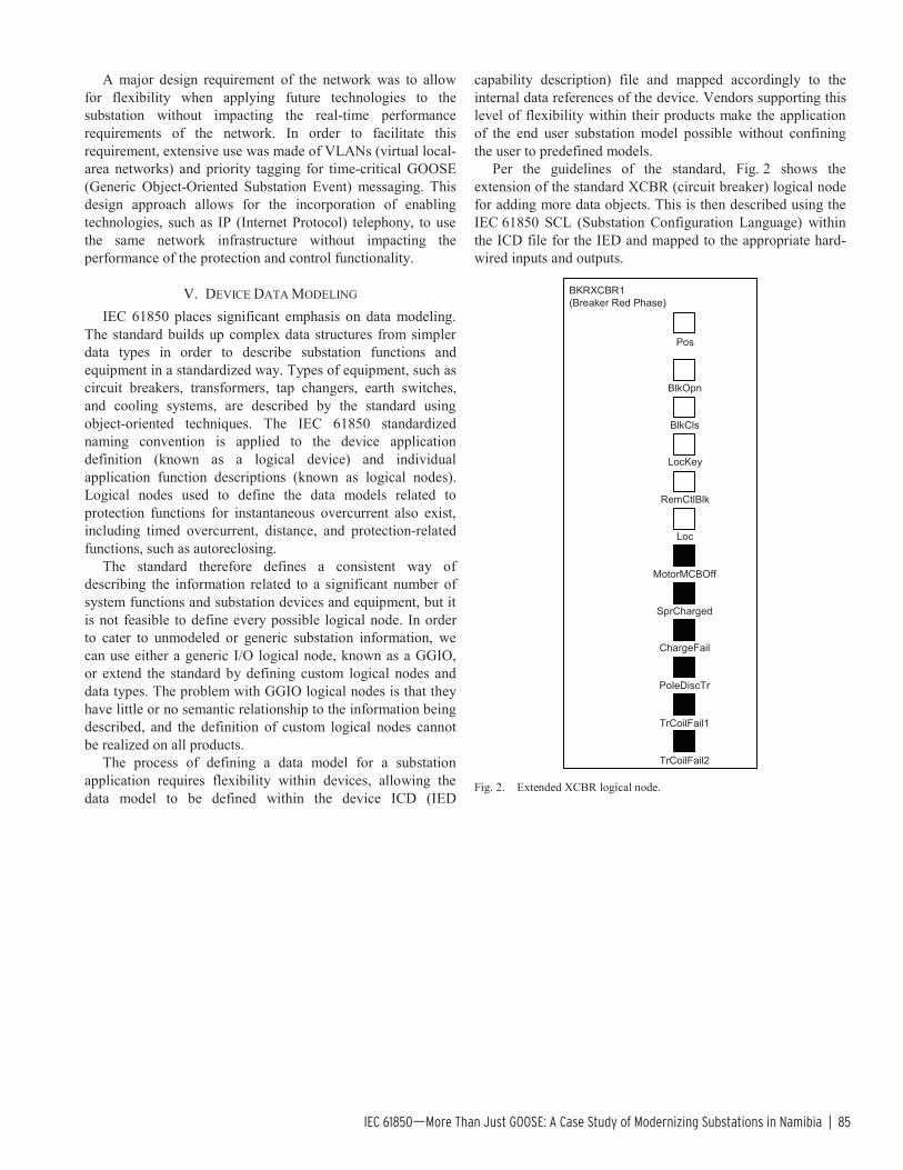
IEC 61850—More Than Just GOOSE: A Case Study of Modernizing Substations in Namibia | 85
A major design requirement of the network was to allow for flexibility when applying future technologies to the substation without impacting the real-time performance requirements of the network. In order to facilitate this requirement, extensive use was made of VLANs (virtual local-area networks) and priority tagging for time-critical GOOSE (Generic Object-Oriented Substation Event) messaging. This design approach allows for the incorporation of enabling technologies, such as IP (Internet Protocol) telephony, to use the same network infrastructure without impacting the performance of the protection and control functionality.
V. DEVICE DATA MODELING IEC 61850 places significant emphasis on data modeling.
The standard builds up complex data structures from simpler data types in order to describe substation functions and equipment in a standardized way. Types of equipment, such as circuit breakers, transformers, tap changers, earth switches, and cooling systems, are described by the standard using object-oriented techniques. The IEC 61850 standardized naming convention is applied to the device application definition (known as a logical device) and individual application function descriptions (known as logical nodes). Logical nodes used to define the data models related to protection functions for instantaneous overcurrent also exist, including timed overcurrent, distance, and protection-related functions, such as autoreclosing.
The standard therefore defines a consistent way of describing the information related to a significant number of system functions and substation devices and equipment, but it is not feasible to define every possible logical node. In order to cater to unmodeled or generic substation information, we can use either a generic I/O logical node, known as a GGIO, or extend the standard by defining custom logical nodes and data types. The problem with GGIO logical nodes is that they have little or no semantic relationship to the information being described, and the definition of custom logical nodes cannot be realized on all products.
The process of defining a data model for a substation application requires flexibility within devices, allowing the data model to be defined within the device ICD (IED
capability description) file and mapped accordingly to the internal data references of the device. Vendors supporting this level of flexibility within their products make the application of the end user substation model possible without confining the user to predefined models.
Per the guidelines of the standard, Fig. 2 shows the extension of the standard XCBR (circuit breaker) logical node for adding more data objects. This is then described using the IEC 61850 SCL (Substation Configuration Language) within the ICD file for the IED and mapped to the appropriate hard-wired inputs and outputs.
BKRXCBR1(Breaker Red Phase)
BlkOpn
BlkCls
LocKey
RemCtlBlk
Loc
MotorMCBOff
SprCharged
ChargeFail
PoleDiscTr
TrCoilFail1
TrCoilFail2
Pos
Fig. 2. Extended XCBR logical node.

86 | Journal of Reliable Power
Fig. 3 shows the use of multiple XCBR logical nodes (one for each phase) and the SIMG (gas insulation supervision) logical node within the same logical device in an IED with the corresponding mapping to a data set to be transported using GOOSE. Describing the model and signal mapping in a diagram greatly simplifies the configuration process and provides suitable documentation for later fault finding and troubleshooting.
• • •
Pos
BlkOpn
BlkCls
LocKey
RemCtlBlk
Loc
MotorMCBOff
SprCharged
ChargeFail
PoleDiscTr
TrCoilFail1
TrCoilFail2
3
5
6
7
8
9
10
11
12
14
15
33
4
2
13
1
• • •
BKRXCBR1(Breaker Red Phase)
I/O Unit 1Data Set: GooseDS
InsAim
InsBlk
BKSIMG1
Fig. 3. XCBR and SIMG logical nodes with GOOSE data set.
Fig. 4 shows the definition of a new logical node that maps the signals contained within a substation yard junction box. Again, the definition was completed following the guidelines of IEC 61850-7-4 Appendix A.
JBSJBX1 (Junction Box)
BB1VTMCB1
BB1VTMCB2
BB1MeasVTMCB
BB2VTMCB1
BB2VTMCB2
BB2MeasVTMCB
ACMCB
CBLoc
IsolLoc
Fig. 4. Custom junction box logical node.
One of the more beneficial aspects of data modeling is that, once modeled, a system easily flows from concept to implementation. A complete model does not easily allow anything to slip through the cracks. It makes testing faster and easier, because the engineer already has a detailed overview to test against, whether it is a small part of the system or some section that comprises all key aspects of the system. It is always much easier to change a model than an implemented system. In other words, data modeling encourages engineers to plan properly.
VI. SUBSTATION AUTOMATION In the past, if a protection signal from one device was
needed in a distant device or in a device in a different building, wiring had to be installed, especially in the case of on-site modifications. This put limitations on device-to-device signaling and substation-wide automation.

IEC 61850—More Than Just GOOSE: A Case Study of Modernizing Substations in Namibia | 87
For example, as illustrated in Fig. 5, if a signal was needed on multiple devices, either the sending device would need a contact per the receiving device or the contact itself would need to be multiplied or cascaded in order to be connected to all receiving devices. Either in series or in parallel, each of these solutions presents difficulties.
Fig. 5. Hard-wired interdevice signaling.
Devices connected via Ethernet networks allow all devices to be interconnected, sometimes spanning many kilometers. This connectivity provides almost unlimited device-to-device signaling. A single IEC 61850 GOOSE message transmission using multicast addressing allows concurrent reception by numerous devices on the same Ethernet subnetwork, shown in Fig. 6, while meeting the timing requirements for protection applications.
ReceivingIED
ReceivingIED
ReceivingIED
ReceivingIED
SendingIED
Ethernet Network Not Limited by Distance
ReceivingIED
Fig. 6. Multicast messaging.
In addition, the flexibility provided by the standard for peer-to-peer signaling allows for substation-wide automation to provide functions and procedures that can eliminate human error. Automated switching procedures, such as live bus changeover and placing a feeder on transfer, can be implemented, allowing the IEDs to automatically and safely complete complex and dangerous switching procedures every time without error.
VII. SYSTEM MANAGEMENT
A. Network Monitoring and Management The Ethernet network is a crucial part of the overall system
and needs to be monitored. Fortunately, monitoring and management technology for Ethernet networks has existed for many years. Many different forms of monitoring and
management strategies and tools exist, such as SNMP (Simple Network Management Protocol). This allows for a clear, present overview of the system and how it is performing. These tools and technologies lead to simpler and faster maintenance, because the system can be monitored and tested while live. There is no need to shut down the system to perform tests. Furthermore, integration of the SNMP functionality into the gateways and HMIs (human-machine interfaces) allows network monitoring to be presented to control centers via SCADA.
B. Configuration Management Configuration management always plays a major role in
the successful implementation of any system. Because IEC 61850 stores its configuration in an open format (ICD, CID [configured IED description], and SCD [system configuration description] files use industry standard XML [Extensible Markup Language]), it is easy to integrate the configuration into existing configuration management systems already being used by engineers. Configuration information is thus readily and easily obtained. Many tools exist to take XML configuration files and perform configuration revision (also built into IEC 61850), alterations, storage, distribution, and many more functions used by engineers.
C. Documentation Detailed and substantial documentation can easily be
generated by combining all of the tools mentioned in Section VII, Subsection B. IEC 61850 can even store some documenting details inside the configurations itself. All of this documentation helps engineers understand, troubleshoot, and train on new systems.
VIII. SIMULATION AND TESTING GOOSE messaging can make testing and simulation much
easier than before. GOOSE tools give an engineer the ability to monitor or reproduce any GOOSE message. This can be done using a laptop (as shown in Fig. 7), turning it into a powerful simulation and monitoring tool.
Fig. 7. Laptop sending simulation GOOSE messages and monitoring system GOOSE messages.
88 | Journal of Reliable Power
A laptop can be used to set up complicated automated testing by sending GOOSE messages to the system and monitoring the results via GOOSE messages or MMS (Manufacturing Message Specification) reports, depending on the particular system configuration. This helps tremendously with testing and engineering time, because there are no temporary wired signals to be set up and wired into the system. The other important advantage of virtual testing is that large substation-wide testing can be done, such as breaker fail trip, during a substation-wide automated feeder-on-transfer sequence.
IX. IMPLICATIONS So what do all of these new technologies and concepts
mean? As mentioned before, Ethernet networks have been around for years and used all over the world in many different forms because of their flexibility, reliability, and speed. Full-time monitoring of all communication is possible. This, coupled with GOOSE messaging, allows engineers to know when their wire is broken in advance rather than having to test for it. This monitoring is available for the relays to use; thus different steps can be put in place to allow for extra flexibility and safety.
IEC 61850 can provide time savings for project and system design, implementation, test, and documentation, all of which impact the bottom line—project cost. Flexible solutions allow for fast scalability of substations, fast integration with existing equipment, and easier adaptation for future applications. Therefore, we can do more with what we have rather than continuously purchasing more equipment.
One of the main implications of an IEC 61850 substation is information distribution. In the past, any signal that was needed by another bay or substation had to be hard-wired if it was to be protection-level secure. By using GOOSE messaging, this same connectivity is achieved via the Ethernet network. The additional benefit is that the same data are available for any relay on the same subnetwork to use without additional wiring. Deciding which applications need information is the only requirement. This capability brings with it an ease of adapting to change or providing solutions to problems that were unforeseen.
X. CONCERNS AND RESOLUTIONS Numerous concerns related to the IEC 61850 standard have
been raised since the standard was published. Most of these concerns are either caused by false assumptions or a misunderstanding of the underlying technologies. Some of the concerns that were addressed during this project include:
• Tripping times and general signaling between devices are significantly faster with hard wires than with GOOSE messaging. This concern proved to be false, and repeated tests highlighted a consistently faster or at least equivalent signaling time achievable using GOOSE messaging. The GOOSE protocol message definition is such that the GOOSE application layer is transported directly using the Ethernet data link layer, thereby eliminating the need to process additional communications layers within the IED firmware.
• Network congestion can cause delays in the delivery of GOOSE messages. This concern is valid only when the features provided by Ethernet technologies are not fully leveraged. Ethernet provides a prioritization scheme and a traffic isolation mechanism by means of VLANs (as defined by IEEE 802.1Q). Hence, a correctly designed Ethernet network can effectively eliminate this perceived risk.
• Many GOOSE messages on the network can overload the IED CPU (central processing unit) with unnecessary processing of GOOSE messages. The IED filters GOOSE messages based on the destination multicast address, and further filtering is possible by the network switches using VLAN tags embedded within the Ethernet frame of the GOOSE message. Unique destination multicast addresses and carefully designed VLAN filtering are therefore essential on large networks.
• The entire system fails when a network failure occurs. A redundant network design is very effective in addressing this failure concern. Many utilities apply a redundancy philosophy that can also be extended to the substation-switched Ethernet network. This project made use of redundant backbone switches with redundant connections from the bay switches to the backbone switches. The bus zone IEDs also used the redundant connections in two separate network switches. Should the highly unlikely catastrophic condition arise where the substation network is rendered unavailable, the protection will still operate, because all instrument transformer inputs and trip coil outputs are wired directly to the protection IEDs.

IEC 61850—More Than Just GOOSE: A Case Study of Modernizing Substations in Namibia | 89
• What if the GOOSE message is not sent or is corrupted in transit? GOOSE messages are constantly sent by transmitting IEDs and may contain the value of several signals, as defined by a data set. Any signal change within a data set speeds up transmission repetition of the GOOSE messages so that the risk of reception failure (because of a corrupt or lost message) is reduced. The reception of GOOSE messages is constantly monitored by associated IEDs, and failure of such reception of any GOOSE message must be suitably alarmed. In addition, a contingency plan must be made within the IED protection and automation logic to change behavior from communications-aided logic to noncommunications-aided logic when GOOSE reception fails.
• How can I test the virtual wiring of GOOSE messages? Physical I/O wiring was replaced with virtual wiring of GOOSE messages communicated between IEDs, but the resulting testable condition remains the same. Is the trip transmitted between IED 1 and IED 2? Does the interlock indicate and function as designed? These are all testable conditions via logic or actual physical operations in an IED. IEDs, test equipment, and software are capable of easily monitoring GOOSE messages, the resulting logic, or the indications resulting from the receipt of GOOSE data. The engineer tool set now includes more network monitoring equipment and software.
XI. TRAINING The issue of staff expertise with the new technology is
often raised as an entrance barrier to IEC 61850 and networking technologies. Many utilities see the technology learning curve as being too high, thus making successful implementation risky.
There is definitely a different skill set required when implementing Ethernet networks and an IEC 61850-based solution. Switched Ethernet networking, data modeling, and new troubleshooting techniques present additional layers of complexity and introduce an additional learning curve to staff not familiar with these technologies.
However, dealing with technological innovations and the evolution of solutions is not new to the energy industry. Utility staff have had to familiarize themselves in the past with the migration from electromechanical to solid state and then to numerical relays. This includes understanding SCADA protocols and related communications issues, the increasing intelligence of multifunctional devices, and the natural blurring of previously clear lines of responsibility. Continuous professional development is a key success factor in any industry.
XII. CONCLUSION Implementing a comprehensively engineered IEC 61850
solution is not a trivial task. Training is a primary issue that must be addressed, because the change in thinking is more revolutionary than evolutionary. Ethernet networks and multifunctional devices blur the distinctions between protection, control, measurements, metering, dc systems, transformer monitoring, disturbance recording, system testing, and most other aspects of the substation environment.
The long-term success of modern substation projects hinges on planning for current technologies and designing for the future. Building substation networks that scale and support devices, such as synchrophasors, merging units and other process bus components, and IP telephony, should be a core consideration of modern system designs. Further success factors include the application of IEC 61850 modeling techniques on a system-wide basis. All equipment vendors should provide flexible devices without compromising functionality.
Finally, the engineering time associated with modern projects should not be underestimated. The potential benefits of IEC 61850 technology in terms of reduced engineering and commissioning times can only be truly experienced once the correct levels of familiarity and experience with the standard and supporting technologies have been gained. However, once this has been achieved, benefits can be realized throughout all aspects of a project. In summary, such projects may not be simple, but they are achievable and certainly worthwhile.
XIII. REFERENCES [1] IEEE Standards for Local and Metropolitan Area Networks—Virtual
Bridged Local Area Networks, IEEE Standard 802.1Q-2005. [2] UCA2.0 Standard Document, Part 1, Electric Power Research Institute
(EPRI), Palo Alto, CA. Available: http://my.epri.com.
XIV. BIOGRAPHIES Dorran D. Bekker received his BSCE in 2007. After working at e-LEK Engineering as an application engineer for a year, he joined Consolidated Power Projects as a SCADA/automation engineer.
Peter Diamandis received his BSEE from the University of the Witwatersrand in Johannesburg, South Africa, in 1991. Currently, he is an independent consultant, formerly of Eskom, working for Trans-Africa Projects.
Tim Tibbals received his BS in electronics engineering from Gonzaga University in 1989. After graduation, he joined Schweitzer Engineering Laboratories, Inc. (SEL) as an application engineer, performing system studies and relay testing. He has also worked as a development engineer and as part of the development team for many of the communications features and functions of SEL products. He subsequently worked as an application engineer for protection, integration, and automation products, assisting customers through product training, seminars, and phone support. He served as the automation services supervisor in the SEL systems and services division for several years before returning to the research and development division as a product engineer for automation and communications engineering products. He is currently a senior automation system engineer in the sales and customer service division.
© 2010 by Consolidated Power Projects, Trans-Africa Projects, and Schweitzer Engineering Laboratories, Inc.
All rights reserved. 20100303 • TP6430-01

90 | Journal of Reliable Power
Ten Tips for Improving the Security of Your Assets Edmund O. Schweitzer, III
November 2009
From the very beginning of SEL, I have stressed the importance of security in our relays, communications processors, meters, and other equipment. From our very first products, we have provided two levels of access with separate passwords and alarm contacts that signal access failures. For many years, we have emphasized the importance of security in integrated systems and published many papers describing threats, attack scenarios, and practical mitigation. In addition, SEL University offers a cybersecurity course, and SEL has several secure-communications products.
In recent years, cybersecurity has become increasingly important. Too many of us have had negative personal experiences, including identity theft, phishing, denial-of-service attacks, viruses, credit card fraud, and bank fraud. Broader threats come from hackers, disgruntled employees, terrorists, and countries with sophisticated information warfare plans and capabilities. These threats are just as real as the ones we may have personally experienced.
Given the rapidly changing world of technology, and the relatively new recognition of the importance of cybersecurity, it often seems as if there is no clear focus on the responsibility for security. Does it belong with the information services people, SCADA folks, protection engineers, customers, suppliers, government? The answer is it’s the responsibility of all of us. It has to be, because modern power systems use so many different kinds of electronic instruments, and so many different means of communications and access, for such a wide variety of purposes.
Fortunately, there are many simple and low-cost steps you can take to quickly reduce the threats to vital power system assets. Here are ten activities that I think you should seriously consider.
1. Know all communications paths to your assets. Make sure to include paths that are accessible locally, such as a thumb drive. Draw a picture!
SCADA EMS Engineering access Maintenance
Telephone lines Wireless Internet System interconnections and bridges
2. Use and manage strong passwords.
SEL equipment makes this easy: you can use virtually all printable ASCII characters. Strengthen a password like the one below with a few changes:
Weak: Webster STRONG: W3b$st3r
Do not use default passwords Change them periodically Change them when people leave
Control them Use different ones in different regions
3. Secure communications with encryption and authentication tools.
Wire, fiber, radio SCADA, engineering access, maintenance

Ten Tips for Improving the Security of Your Assets | 91
4. Practice a “need-to-know” policy, compartmentalize knowledge—even guard your access tools.
Keep your designs safe, and limit access to system details to those who really need to know to do their job. Be especially careful to protect:
Computers Passwords Encryption equipment and keys
Instruction manuals Software
5. For key assets, have more than one (secure!) communications path.
Minimize impact of denial-of-service attack Send security alarms through a second path
6. Take action now. Don’t wait for a government mandate or for an attack.
7. Review log files on firewalls, alarms, and access activity.
8. Don’t forget physical security.
9. Practice “security in depth.”
Physical Cyber Communications
Training Culture
10. Have an incident response plan ready ahead of time.
So a cyber event happens—now what? During the event is not the best time to create a plan and try it out. Have a clear, concise, and well-thought-out plan in place beforehand about how your company will respond to a cyber incident.

92 | Journal of Reliable Power
Communications and Protocols Bibliography Issue 2 of the Journal of Reliable Power
Achanta, Shankar, Brian MacLeod, Eric Sagen, and Henry Loehner. “Apply Radios to Improve the Operation of Electrical Protection.” Presented October 2010 at the Western Protective Relay Conference (Spokane, Washington).
Salmon, Doug, Mark Zeller, Armando Guzmán, Venkat Mynam, and Marcos Donolo. “Mitigating the Aurora Vulnerability With Existing Technology.” Presented May 2010 at the Georgia Tech Protective Relaying Conference (Atlanta, Georgia).
Greer, Richard, Will Allen, Jim Schnegg, and Andrew Dulmage. “Distribution Automation Systems With Advanced Features.” Presented May 2010 at the Smart Grid RoadShow (Cincinnati, Ohio).
Celluri, Saroj, Diego Rodas, and Ala Harikrishna. “Integration Considerations for Large-Scale IEC 61850 Systems.” Presented April 2010 at the Western Power Delivery Automation Conference (Spokane, Washington).
Vaughn, Michael, Robert Schloss, Scott Manson, Sai Raghupathula, and Trent Maier. “Idaho Power RAS: A Dynamic Remedial Action Case Study.” Presented May 2010 at the Georgia Tech Protective Relaying Conference (Atlanta, Georgia).
Bekker, Dorran D., Peter Diamandis, and Timothy Tibbals. “IEC 61850 — More Than Just GOOSE: A Case Study of Modernizing Substations in Namibia.” Presented April 2010 at the Western Protective Delivery Automation Conference (Spokane, Washington).
Anderson, Dwight, and Nathan Kipp. “Implementing Firewalls for Modern Substation Cybersecurity.” Presented April 2010 at the Western Power Delivery Automation Conference (Spokane, Washington).
Dolezilek, David, David Whitehead, and Veselin Skendzic. “Integration of IEC 61850 GSE and Sampled Value Services to Reduce Substation Wiring.” Presented April 2010 at the Western Power Delivery Automation Conference (Spokane, Washington).
Dolezilek, David, and Laura Hussey. “Requirements or Recommendations? Sorting Out NERC CIP, NIST, and DOE Cybersecurity.” Presented April 2010 at the Western Power Delivery Automation Conference (Spokane, Washington).
Ewing, Chris. “Engineering Defense-in-Depth Cybersecurity for the Modern Substation.” Presented April 2010 at the Western Power Delivery Automation Conference (Spokane, Washington).
Atienza, Edsel. “Testing and Troubleshooting IEC 61850 GOOSE-Based Control and Protection Schemes.” Presented April 2010 at the Western Power Delivery Automation Conference (Spokane, Washington).
Fodero, Ken, Chris Huntley, and David Whitehead. “Secure, Wide-Area Time Synchronization.” Presented April 2010 at the Western Power Delivery Automation Conference (Spokane, Washington).
Thompson, Michael, and Dale Kopf. “Reactive Power Control System for Wind Farm Application Using IEC 61850.” Presented March 2010 at DistribuTECH (Tampa, Florida).
Fischer, Harold, Jeffrey Gilbert, Greg Morton, Michael Boughman, and David Dolezilek. “Case Study: Revised Engineering and Testing Practices Resulting From Migration to IEC 61850.” Presented March 2010 at the Clemson University Power Systems Conference (Clemson, South Carolina).
Dolezilek, David. “Case Study Examples of Interoperable Ethernet Communications Within Distribution, Transmission, and Wide-Area Control Systems.” Presented November 2009 at Grid-Interop (Denver, Colorado).
Bernardes, Renan, and Fernando Ayello. “PQMS — Power Quality Monitoring System: Improve Power Systems Through IEDS.” Presented June 2009 at the International Conference and Exhibition on Electricity Distribution (Prague, Czech Republic).

Communications and Protocols Bibliography | 93
IEEE-IAS Cement Industry Committee, Karl Zimmerman, and Ryan McDaniel. “Using Power System Event Data to Reduce Downtime.” Presented June 2009 at the IEEE-IAS/PCA Cement Industry Technical Conference (Palm Desert, California).
Miller, Dean, Robert Schloss, Scott Manson, Sai Raghupathula, and Trent Maier. “PacifiCorp’s Jim Bridger RAS: A Dual Triple Modular Redundant Case Study.” Presented April 2009 at the Western Power Delivery Automation Conference (Spokane, Washington).
Blanchette, Daniel, and Michael Dood. “Case Study of Redundant Control System at Manitoba Hydro.” Presented April 2009 at the Western Power Delivery Automation Conference (Spokane, Washington).
Tengdin, John, Ken Fodero, and Ron Schwartz. “Ensuring Error-Free Performance of Communications Equipment.” Presented April 2009 at the Western Power Delivery Automation Conference (Spokane, Washington).
Tran, Thai, Binh Le, Cuong Nguyen, and Sarah Hughes. “Application of an IEC 61850 and Synchrophasor Solution for Electricity of Vietnam.” Presented April 2009 at the Western Power Delivery Automation Conference (Spokane, Washington).
Skendzic, Veselin, and Gary Scheer. “Performance of Redundant Ethernet Networks for Electric Substation Instrumentation and Control.” Presented April 2009 at the Western Power Delivery Automation Conference (Spokane, Washington).
Smith, Rhett. “Cryptography Concepts and Effects on Control System Communications.” Presented April 2009 at the Western Power Delivery Automation Conference (Spokane, Washington).
Dolezilek, David, and Stephanie Schweitzer. “Practical Applications of Smart Grid Technologies.” Presented April 2009 at the Western Power Delivery Automation Conference (Spokane, Washington).
Anderson, Dwight. “Securing Modern Substations With an Open Standard Network Security Solution.” Presented April 2009 at the Western Power Delivery Automation Conference (Spokane, Washington).
Sagen, Eric, and Kenneth Workman. “Methods of Time Synchronization.” Presented April 2009 at the Georgia Tech Protective Relaying Conference (Atlanta, Georgia).
Whitehead, David, and Rhett Smith. “Cryptography: A Tutorial for Power Engineers.” Presented October 2008 at the Western Protective Relay Conference (Spokane, Washington).
Fodero, Ken, and Adrian Silgardo. “Protection and the Communications Network: Can You Hear Me Now?” Presented October 2008 at the Western Protective Relay Conference (Spokane, Washington).
Gorrell, Ernie, James Niemira, and Eli Nelson. “Distribution Automation Helps Revitalize Community.” Presented October 2008 at the Western Protective Relay Conference (Spokane, Washington).
Hou, Daqing, and David Dolezilek. “IEC 61850 — What It Can and Cannot Offer to Traditional Protection Schemes.” Presented October 2008 at the Western Protective Relay Conference (Spokane, Washington).
Allen, Will. “Effects of Wide-Area Control on the Protection and Operation of Distribution Networks.” Presented October 2008 at the Western Protective Relay Conference (Spokane, Washington).
Novak Jr., John J., and Richard Kirby. “Better, Faster, and More Economical Integrated Protective Relaying and Control Using Digital Bits and Logic.” Presented September 2008 at the IEEE Petroleum and Chemical Industry Committee Technical Conference (Cincinnati, Ohio).
Jenkins, Robin, and David Dolezilek. “Case Study: Using IEC 61850 Methods for RTU Replacement and Distributed Automation.” Presented April 2008 at the Western Power Delivery Automation Conference (Spokane, Washington).
Rosenberger, Todd, David Prestwich, Matthew Watkins, and Mark Weber. “Automated Event Retrieval Reduces Operating Costs.” Presented April 2008 at the Western Power Delivery Automation Conference (Spokane, Washington).
Kimura, Sergio, Andre Rotta, Ricardo Abboud, Rogério Moraes, Eduardo Zanirato, , and Juliano Bahia. “Applying IEC 61850 to Real Life: Modernization Project for 30 Electrical Substations.” Presented April 2008 at the Western Power Delivery Automation Conference (Spokane, Washington).

94 | Journal of Reliable Power Communications and Protocols Bibliography | 94
Bradetich, Ryan, and Paul Oman. “Implementing SCADA Security Policies Via Security-Enhanced Linux.” Presented April 2008 at the Western Power Delivery Automation Conference (Spokane, Washington).
Seeley, Nicholas. “Automation at Protection Speeds: IEC 61850 GOOSE Messaging as a Reliable, High-Speed Alternative to Serial Communications.” Presented April 2008 at the Western Power Delivery Automation Conference (Spokane, Washington).
Coppel, Shawn, Timothy Tibbals, and Adrian Silgardo. “Practical Considerations for Ethernet Networking Within Substations.” Presented April 2008 at the Western Power Delivery Automation Conference (Spokane, Washington).
Dolezilek, David. “IEC 61850 GOOSE and IEEE C37.118 Synchrophasors Used for Wide-Area Monitoring and Control, SPS, RAS, and Load and Generation Management.” Presented April 2008 at CIGRE (St. Petersburg, Russia).
Anderson, Dwight, and Garrett Leischner. “Cybersecurity as Part of Modern Substations.” Presented March 2008 at the Clemson University Power Systems Conference (Clemson, South Carolina).
Hill, Jeff, and Ken Behrendt. “Upgrading Power System Protection to Improve Safety, Monitoring, Protection, and Control.” Presented March 2008 at the IEEE Pulp and Paper Industry Technical Conference (Seattle, Washington).
Bradetich, Ryan, and Paul Oman. “Connecting SCADA Systems to Corporate IT Networks Using Security-Enhanced Linux.” Presented October 2007 at the Western Protective Relay Conference (Spokane, Washington).
Hurd, Steven, Rhett Smith, and Garrett Leischner. “Tutorial: Security in Electric Utility Control Systems.” Presented October 2007 at the Western Protective Relay Conference (Spokane, Washington).
Flores, Victor Manuel, Daniel Espinosa, Julian Alzate, and David Dolezilek. “Case Study: Design and Implementation of IEC 61850 From Multiple Vendors at CFE La Venta II.” Presented April 2007 at the Western Power Delivery Automation Conference (Spokane, Washington).
Leischner, Garrett, and Cody Tews. “Security Through VLAN Segmentation: Isolating and Security Critical Assets Without Loss of Usability.” Presented October 2007 at the Western Protective Relay Conference (Spokane, Washington).
Scheer, Gary, and David Dolezilek. “Selecting, Designing, and Installing Modern Data Networks in Electrical Substations.” Presented October 2007 at the Western Protective Relay Conference (Spokane, Washington).
Tibbals, Timothy, and David Dolezilek. “More Than Communication — The Engineering Approach of IEC 61850.” Presented April 2007 at the International Advanced Power System Automation Conference (Jeju, South Korea).
West, Ed, Ken Graves, and Dick Martin. “Dairyland Power Installs Multifunction High-End Meters and Expanded Wide Area I/P Communications for Metering and Real-Time Data Collection.” Presented March 2007 at the Clemson University Power Systems Conference (Clemson, South Carolina).
Thompson, Michael. “The Power of Modern Relays Enables Fundamental Changes in Protection and Control System Design (Build a Substation That Continually Tests Itself).” Presented June 2006 at the IEEE Pulp and Paper Industry Technical Conference (Appleton, Wisconsin).
Kirby, Richard and Ronald Schwartz. “Microprocessor-Based Protective Relays Deliver More Information and Superior Reliability With Lower Maintenance Costs.” Presented in April 2006 at the IEEE Industrial and Commercial Power Systems Technical Conference (Detroit, Michigan).
Leischner, Garrett, and David Whitehead. “A View Through the Hacker’s Looking Glass.” Presented April 2006 at the Western Power Delivery Automation Conference (Spokane, Washington).
Rice, James and Nicholas Seeley. “Integrating Remotely Located Substations Into SCADA Systems: A Case Study Using Commercially Available Satellite Internet Service Providers for SCADA Communications.” Presented April 2006 at the Western Power Delivery Automation Conference (Spokane, Washington).

Communications and Protocols Bibliography | 95
Skendzic, Veselin, and Roger Moore. “Extending the Substation LAN Beyond Substation Boundaries: Current Capabilities and Potential New Protection Applications of Wide-Area Ethernet.” Presented April 2006 at the Western Power Delivery Automation Conference (Spokane, Washington).
Risley, Allen, and Kevin Carson. “Low- or No-Cost Cybersecurity Solutions for Defending the Electric Power System Against Electronic Intrusions.” April 2006.
Dolezilek, David, Robin Jenkins, Mike Agudo , and Dave Fox. “Case Study: Integrate Substation IEDs to Provide Reliable, Independent Dual-Primary Remedial Action Schemes.” Presented March 2006 at the Clemson University Power Systems Conference (Clemson, South Carolina).
Tibbals, Timothy, and David Dolezilek. “Substation Communication Techniques to Satisfy NERC Urgent Action Standard 1200.” Presented March 2006 at the Clemson University Power Systems Conference (Clemson, South Carolina).
Behrendt, Ken, and Ken Fodero. “The Perfect Time: An Examination of Time-Synchronization Techniques.” Presented February 2006 at DistribuTECH (Tampa, Florida).
Hataway, Greg, Ted Warren, and Chris Stephens. “Implementation of a High-Speed Distribution Network Reconfiguration Scheme.” Presented October 2005 at the Western Protective Relay Conference (Spokane, Washington).
Scheer, Gary, and Roy Moxley. “Digital Communications Improve Contact I/O Reliability.” Presented May 2005 at the Western Power Delivery Automation Conference (Spokane, Washington).
Dolezilek, David. “IEC 61850: What You Need to Know About Functionality and Practical Implementation.” Presented May 2005 at the Western Power Delivery Automation Conference (Spokane, Washington).
Risley, Allen, and David Whitehead. “SEL-3021 Wireless Interface Security.” February 2005.
Labuschagne, Casper, and Izak van der Merwe. “Programmability of Numerical Relays: A Busbar Protection Relay Serves as a Traditional RTU.” Presented November 2004 at the Southern African Conference on Power System Protection (Johannesburg, South Africa).
Moxley, Roy, and Ken Fodero. “High-Speed Distribution Protection Made Easy: Communications-Assisted Protection Schemes for Distribution Automation.” Presented October 2004 at the Western Protective Relay Conference (Spokane, Washington).
Dolezilek, David. “Methods for Securing Substation Relay Communications.” Presented October 2004 at the Western Protective Relay Conference (Spokane, Washington).
Guzmán, Armando, Demetrios Tziouvaras, and Ken Martin. “Local and Wide-Area Network Protection Systems Improve Power System Reliability.” Presented October 2004 at the Western Protective Relay Conference (Spokane, Washington).
Fodero, Ken, and Girolamo Rosselli. “Applying Digital Current Differential Systems Over Leased Digital Service.” Presented October 2004 at the Western Protective Relay Conference (Spokane, Washington).
Dolezilek, David, and Brian McDermott. “Remote Data Monitoring and Data Analysis for Substations — A Case Study in Implementation.” Presented April 2004 at the Western Power Delivery Automation Conference (Spokane, Washington).
Dolezilek, David. “Methods for Securing Substation LAN Communications.” Presented April 2003 at the Western Power Delivery Automation Conference (Spokane, Washington).
Guzmán, Armando, Manglio Lopez, Jorge Díaz, and Enrique Priego-Franco. “Sending Protection and Automation Data Over PEMEX Ethernet Network: A Case Study.” Presented April 2003 at the Western Power Delivery Automation Conference (Spokane, Washington).
Risley, Allen, Jeff Roberts, and Peter LaDow. “Electronic Security of Real-Time Protection and SCADA Communications.” Presented April 2003 at the Western Power Delivery Automation Conference (Spokane, Washington).

96 | Journal of Reliable Power
Dolezilek, David, Kevin Carson, Kevin Leech, and Kevin Streett. “Secure SCADA and Engineering Access Communications: A Case Study of Private and Public Communication Link Security.” Presented April 2003 at the Western Power Delivery Automation Conference (Spokane, Washington).
Zimmerman, Karl, and Mike Collum. “Implementing Distribution Automation and Protection.” Presented April 2003 at the Western Power Delivery Automation Conference (Spokane, Washington).
Risley, Allen, and Jeff Roberts. “Electronic Security Risks Associated With Use of Wireless, Point-to-Point Communications in the Electric Power Industry.” Presented February 2003 at DistribuTECH (Las Vegas, Nevada).
Oman, Paul, Allen Risley, Jeff Roberts, and Edmund O. Schweitzer III. “Attack and Defend Tools for Remotely Accessible Control and Protection Equipment in Electric Power Systems.” Presented April 2002 at the Texas A&M University Relay Conference (College Station, Texas).
Moxley, Roy, and Darold Woodward. “Improve Substation Control and Protection by Communication of Analog Information.” Presented April 2002 at the Western Power Delivery Automation Conference (Spokane, Washington).
Oman, Paul, Jeff Roberts, and Edmund O. Schweitzer, III. “Tools for Protecting Electric Power Systems From Electronic Intrusions.” Presented April 2002 at the Western Power Delivery Automation Conference (Spokane, Washington).
Streett, Kevin, Kevin Leech, and Greg Rauch. “Power Delivery System Integration and Automation at Overton Power District No. 5 Overton, Nevada.” Presented April 2002 at the Western Power Delivery Automation Conference (Spokane, Washington).
McDermott, Brian, David Dolezilek, and Timothy Tibbals. “Proven Drop-In Control House Turnkey Solution for Total Protection, Monitoring, Automation, and Control of T&D Substations: A Case Study in Justification and Implementation.” Presented March 2002 at DistribuTECH (Miami Beach, Florida).
Oman, Paul, Edmund O. Schweitzer, III, and Jeff Roberts. “Safeguarding IEDs, Substations, and SCADA Systems Against Electronic Intrusions.” Presented April 2001 at the Western Power Delivery Automation Conference (Spokane, Washington).
Scheer, Gary, and Darold Woodward. “Speed and Reliability of Ethernet Networks for Teleprotection and Control.” Presented April 2001 at the Western Power Delivery Automation Conference (Spokane, Washington).
Dolezilek, David, and Lee Margaret Ayers. “Using Dynamic Real-Time Substation Information to Reinvent Asset Management.” Presented April 2001 at the Western Power Delivery Automation Conference (Spokane, Washington).
Fairman, James, Karl Zimmerman, Jeff Gregory, and James Niemira. “International Drive Distribution Automation and Protection.” Presented October 2000 at the Western Protective Relay Conference (Spokane, Washington).
Oman, Paul, Edmund O. Schweitzer, III, and Deborah Frincke. “Concerns About Intrusions Into Remotely Accessible Substation Controllers and SCADA Systems.” Presented October 2000 at the Western Protective Relay Conference (Spokane, Washington).
Rauch, Greg. “Optimized Distribution Feeder Protection With Remote and Local Control.” Presented February 2000 at DistribuTECH (San Diego, California).
Schweitzer III, Edmund O., and Gary Scheer. “SEL Products and Features Make Integration Easy.” November 1999.
Dolezilek, David. “Case Study of a Large Transmission and Distribution Substation Automation Project.” Presented November 1999 at the International Transmission & Distribution Conference & Exhibition (Brisbane, Australia).
Dolezilek, David, and Dean Klas. “Using Information From Relays to Improve the Power System.” Presented November 1999 at the International Transmission & Distribution Conference & Exhibition (Brisbane, Australia).
Dolezilek, David. “Power System Automation.” Presented May 1999 at the Northwest Lineman College.

Diehl, Mark, Robert Crognale, and James Schwenk. “Microprocessor Relay Capabilities Improve Protection, SCADA, and Maintenance: PECO Energy Company’s Westmoreland Rebuild Project.” Presented October 1999 at the Western Protective Relay Conference (Spokane, Washington).
Behrendt, Ken. “Relay-to-Relay Digital Logic Communication for Line Protection, Monitoring, and Control.” Presented November 1998 at the CEPSI Exhibition (Bangkok, Thailand).
Roberts, Jeff, and Karl Zimmerman. “Trip and Restore Distribution Circuits at Transmission Speeds.” Presented October 1998 at the Western Protective Relay Conference (Spokane, Washington).
Schweitzer, III, Edmund O., Gary Scheer, and David Dolezilek. “Comparison of SEL-2020 Star Network to Shared Networks.” March 1997.
Scheer, Gary, and David Dolezilek. “Nonconventional System Design for Flexible Data Retrieval and Use.” January 1997.
Zimmerman, Karl, and Edmund O. Schweitzer, III. “Substation Communications: When Should I Use EIA-232, EIA-485, and Optical Fiber?” Presented November 1996 at the Minnesota Power Systems Conference (St. Paul, Minnesota.)
Behrendt, Ken, and Michael Dood. “Substation Relay Data and Communication.” Presented October 1995 at the Western Protective Relay Conference (Spokane, Washington).
Communications and Protocols Bibliography | 97

98 | Journal of Reliable Power
SEL UniversityTraining Where You Are
On-Site Courses
Classroom Courses
Flexible E-Learning Courses
SEL University, through its affiliation with the International Association for Continuing Education and Training (IACET), is authorized to provide continuing education units (CEUs) for all courses.
SEL University instructors are industry experts with a wealth of technical knowledge and practical experience. Courses focus on practical applications and real-world problem solving, and include the latest advances in power system protection and integration technology. Specialized courses address real-world issues in managing power systems by teaching topics such as modern communications protocols and applied syn-chrophasor technology. To ensure that instruction is relevant and at the appropriate technical level, stu-dent feedback is always requested and evaluated.
Three convenient training options offering courses on:
• IT and Automation• Metering• Motors• WBT and CBT Training
Resources
• Arc-Flash Hazards• Communications• Overhead Transmission• Power Systems• Protection• Substation Maintenance
and Monitoring
Visit www.selinc.com/selu for a complete schedule of SEL University courses and registration information.
Training the Next Generation of Power Systems Engineers

Pullman, Washington USATel: +1.509.332.1890 • Fax: +1.509.332.7990 • www.selinc.com • [email protected]
© 2010 by Schweitzer Engineering Laboratories, Inc.
Modern Solutions for Protection, Control, and Monitoring of Electric Power Systems
Edited by Héctor J. Altuve Ferrer and Edmund O. Schweitzer, IIIThe most comprehensive work of its kind, this book consolidates modern solutions for protecting, controlling, and monitoring electric power systems into one volume. You will find straightforward presentations and example applications of the following technologies and much more:
• Time-synchronized protection, monitoring, and control
• Wide-area protection and control using synchrophasors
• Cybersecurity threats and a security-in-depth toolkit
• Distribution systems that safely operate and rapidly restore power after faults
• Transmission protection solutions that improve stability, detect power swings, and help you get the most out of your primary equipment
Price: $151.21 USD Complete the form below, or place your order online at www.selinc.com/bookstore.
Order Your Copy Today!For more information about this book as well as other SEL technical books, please visit www.selinc.com/bookstore.
Name Title
Company Name Phone Number
Address 1 Fax Number
Address 2 Email Address
City State Postal Code
Book Price No. of Books Subtotal
Modern Solutions for Protection, Control, and Monitoring of Electric Power Systems
$151.21 USD
Sales Tax
TOTAL
SEL USE ONLY
Sales Order No. Date Entered Date ShippedOrder Online Fax Mail www.selinc.com/bookstore +1.509.332.7990 SEL • 2350 NE Hopkins Court Pullman, WA 99163 Attn: Customer Service
Purchase Type: q Business q Personal Method of Payment: q Check q Cash q Credit Card
Credit Card Type Credit Card Number
Name on Card Expiration Date
Billing Address City State Postal Code


©2010 Schweitzer Engineering Laboratories, Inc. 20100915