deploying digital substations - energypa.orgenergypa.org/assets/files/2017/sept...
TRANSCRIPT

Imagination at work
Deploying Digital Substations
September, 2017
GE Proprietary Information—Class III (Confidential)
Export Controlled—U.S. Government approval is required prior
to export from the U.S., re-export from a third country, or
release to a foreign national wherever located.
Harsh Vardhan – GE Grid Solutions
Wojciech Szela - PECO

MDS WiYZTMIEC 61850 Digital Substation

MDS WiYZTMProcess Bus Introduction
The standard: IEC 61869-9 DIGITAL INTERFACE FOR INSTRUMENT TRANSFORMERS• Replaces IEC 60044-8 digital solution• Provides a product standard for instrument transformers with a digital interface
according to 61850 Includes backward compatibility for IEC 61850-9-2• Uses IEC 61588 for time synchronization
The standard: IEC 61850-9-2 (Ed.1)• Standard for communication networks and systems in substations – Part 9-2:
Specific communication service mapping (SCSM) – Sampled values over ISO/IEC 8802-3
• The standard was very broad, leaving wide room for interpretation which complicates interoperability
Implementation Guideline for digital interface to Instrument transformers using IEC 61850-9-2• To facilitate implementation and enable interoperability, the UCA International
Users Group created a guideline that defines an application profile of IEC 61850-9-2
• Commonly referred to as IEC 61850-9-2 LE (Light Edition)
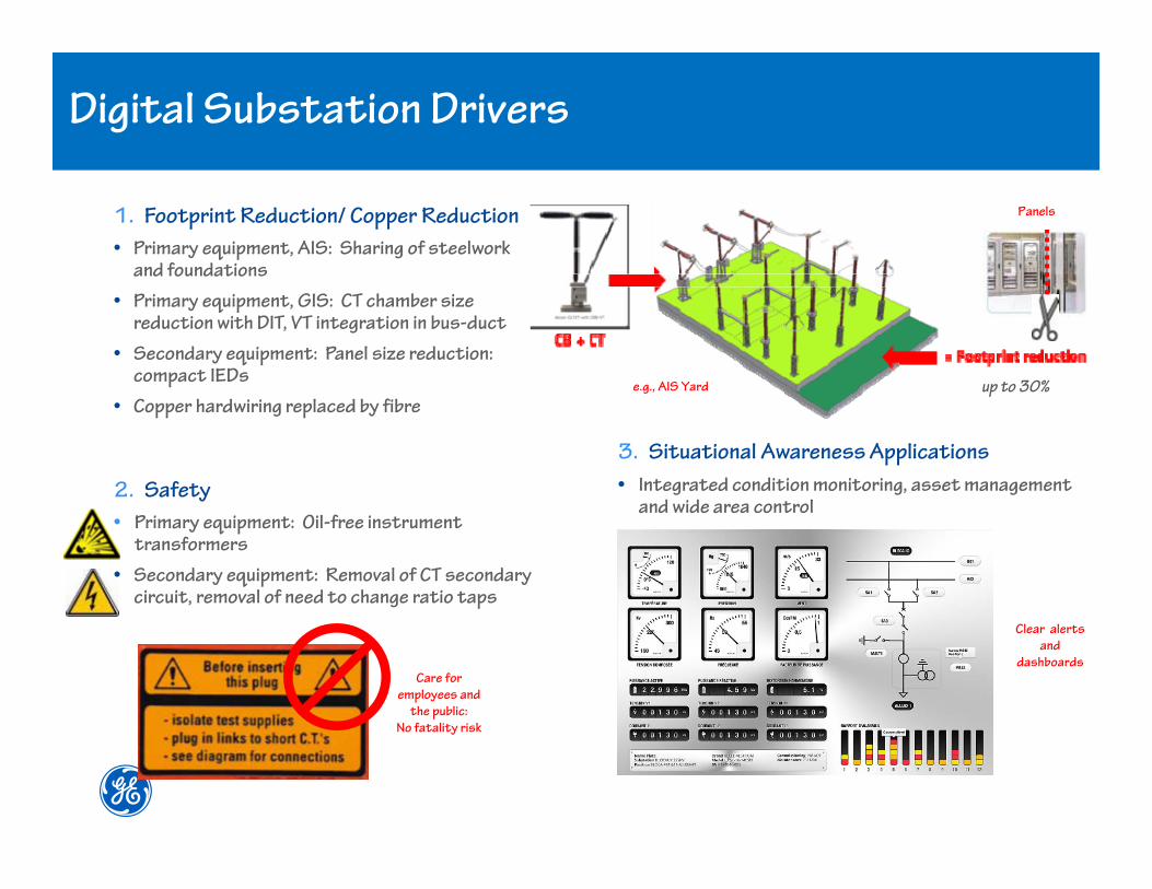
MDS WiYZTMDigital Substation Drivers
3. Situational Awareness Applications
• Integrated condition monitoring, asset management and wide area control
1. Footprint Reduction/ Copper Reduction
• Primary equipment, AIS: Sharing of steelwork and foundations
• Primary equipment, GIS: CT chamber size reduction with DIT, VT integration in bus-duct
• Secondary equipment: Panel size reduction: compact IEDs
• Copper hardwiring replaced by fibre
Care for
employees and
the public:
No fatality risk
Clear alerts
and
dashboards
up to 30%
Panels
e.g., AIS Yard
2. Safety
• Primary equipment: Oil-free instrument transformers
• Secondary equipment: Removal of CT secondary circuit, removal of need to change ratio taps

PECO Digital Substation PilotPOST Substation
GE Proprietary 69/18/2017
MDS WiYZTMPECO POST Substation Pilot
Purpose - To implement the digital substation technology in the
substation as a “proof of concept”, learn and understand different
components of a digital substation and compare it with the existing
conventional technology.
Scope - The scope of the project involves supplying a complete
digital solution for the protection & control of a 230kV Line
consisting two Circuit Breakers.
Name of the substation: POST Substation
Location: Philadelphia, PA
Total Number of Bays: 12
Digital Substation Pilot Bays: 2
Commissioning Date: May, 2017

Selection of Equipment

GE Proprietary 89/18/2017
MDS WiYZTMPrimary Equipment – Optical CT
GE Proprietary 99/18/2017
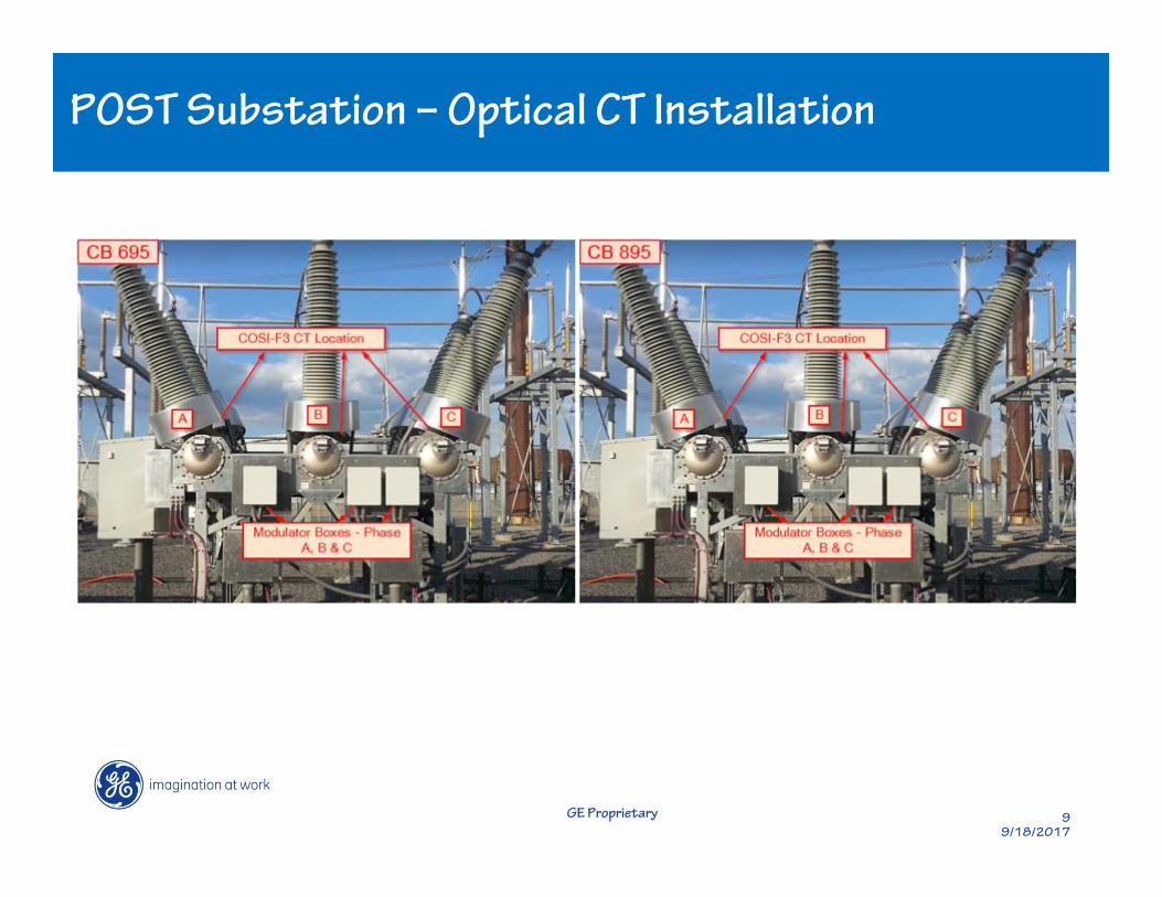
MDS WiYZTMPOST Substation – Optical CT Installation

GE Proprietary 109/18/2017
MDS WiYZTMPrimary Interface Devices - Merging Units, Switchgear Control Unit
Merging Units
• Merging Units are used to merge the output signal from COSI-F3
Optical current transformers and conventional VTs to produce the 9-
2LE Sampled value streams
• 80 Samples/ Cycle
Switchgear Control Units
• SCU is used to interface with the Circuit Breakers, Isolators, earth
switches etc.. The Circuit breaker status inputs (52a and 52b
contacts) are hard wired to the SCU. SCU then communicates these
signals to the protection and control devices on the station bus.
• Protection Trips, CB control commands are sent via SCU
GE Proprietary 119/18/2017
MDS WiYZTM9-2LE Protection Relay
• A Line distance protection relay supporting IEC 61850 9-
2LE is selected. The relay can subscribe to multiple
streams of 9-2LE sampled values.
• Each primary and backup system has one such relay.
• The primary protection relay subscribes to the sampled
values coming from the primary Merging units, MU-CB895
and MU-CB695
• Backup protection relay subscribes to the sampled values
coming from the backup Merging units, MU-CB895 and MU-
CB695
• Relays have self monitoring & Diagnostic features

GE Proprietary 129/18/2017
MDS WiYZTMEthernet Switch, Substation Server
A substation server (with HMI) supporting IEC61850 Client functionality is
also provided for local monitoring & engineering of the system. All the
Equipment (Protection relays, Merging units, GPS clock etc.) could be
accessed via the HMI PC
Ethernet switches are required to make the necessary Ethernet network
for process bus and station bus. Ethernet switches selected in the
project also supports the functionality of PTP Transparent clocks for the
time distribution using PTP.

GE Proprietary 139/18/2017
MDS WiYZTMGPS Clock – Time Synchronization
Equipment Time synchronization Method
Protection Relay PTP (Precision Time Protocol)
SCU PTP (Precision Time Protocol)
Merging Units PPS (Pulse Per Second) over Fiber
Substation Server SNTP (Simple Network Time Protocol)
HMI PC SNTP (Simple Network Time Protocol)
Redundant GPS Clocks
GPS Clock Antenna

GE Proprietary 149/18/2017
MDS WiYZTMPOST Substation Architecture
• Two independent Systems –
Primary System and Backup
• 100% Equipment
Redundancy (except for
substation server and HMI)

GE Proprietary 159/18/2017
MDS WiYZTMPOST Substation – Communication Optimization(Segregating Process bus and Station Bus)
Optimization of the Ethernet
Traffic:
• V-LAN Filtering
OR
• MAC address Filtering
Installation, Testing & Commissioning

GE Proprietary 179/18/2017
MDS WiYZTMOptical CTs – Installation, Testing & Commissioning
• Each Circuit Breaker has two sets of COSI-F3 CTs on each phase
(A, B & C)
• CTs are pre-calibrated at the factory for a stated accuracy for a
given range of primary current
• No need to worry about the CT ratios and CT polarities.

GE Proprietary 189/18/2017
MDS WiYZTMSecondary Equipment – Installation, Testing & Commissioning
• All the secondary equipment is mounted in the panels
• All equipment are pre-tested during FAT
• Configuration tool for Process Bus Relays is same as for
conventional Relays
• Settings for Process Bus Relays is same as for conventional
Relays with some additional settings such as SvId, time sync
etc.
• Secondary Injection kit supporting 9-2LE is used to test the
relays

GE Proprietary 199/18/2017
MDS WiYZTMSelf-Diagnostic & Monitoring System
• All the devices in the system have self-diagnostic capabilities so the
end user does not have to spend much time troubleshooting the
system.
• If there is any failure in receiving the digital signal from the optical CTs
mounted in the field, the merging unit will generate an alarm for this.
Moreover, the merging unit will also raise the corresponding quality
flag for this in the sampled value frames so that the subscribing
protection relay would know about this failure and would act
accordingly.
• If the protection relay fail to subscribe to any of the two merging units
or if the samples coming from any of the merging units are not time
synchronized, the relay will generate an alarm for this. Another
example, If the SCU fails to subscribe the GOOSE signals from the
protection relay, the SCU will generate an alarm for this and send it to
the SCADA.

GE Proprietary 209/18/2017
MDS WiYZTMPOST Substation Logical Wiring Diagram
GE Proprietary 219/18/2017
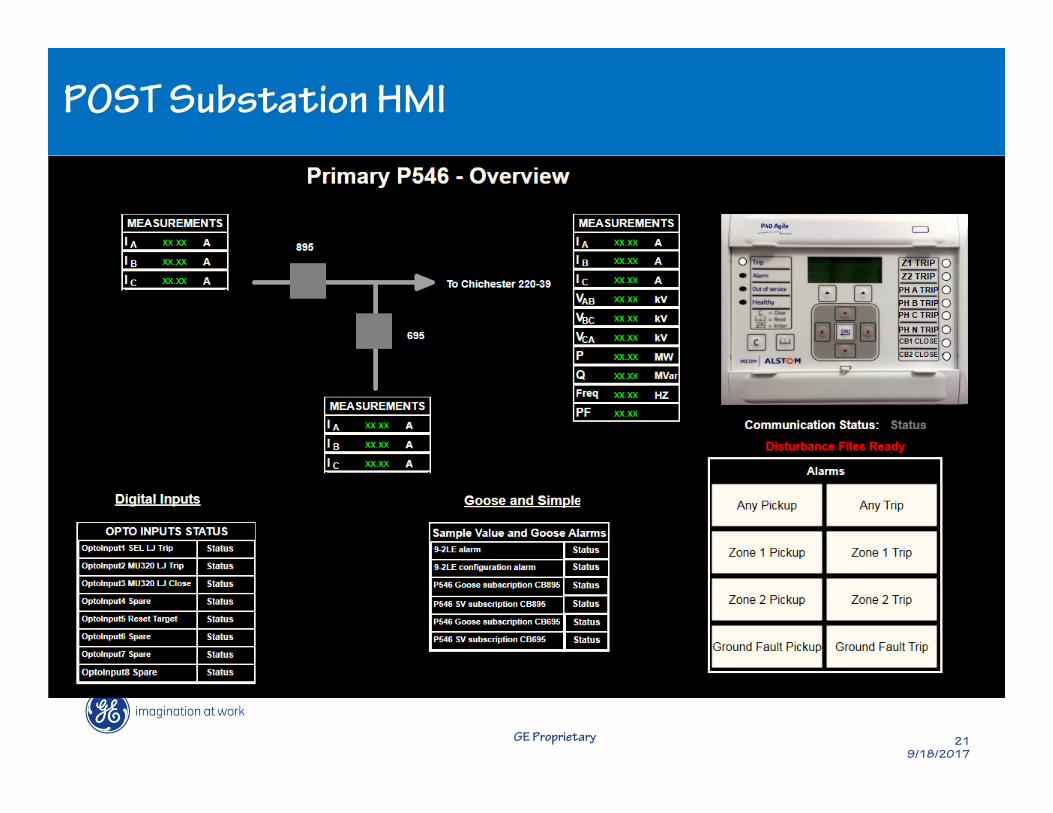
MDS WiYZTMPOST Substation HMI
GE Proprietary 229/18/2017
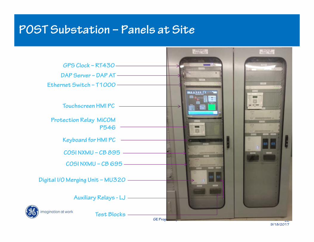
MDS WiYZTMPOST Substation – Panels at Site
GPS Clock – RT430
Ethernet Switch – T1000
DAP Server – DAP AT
Touchscreen HMI PC
Protection Relay MiCOM
P546
Keyboard for HMI PC
COSI NXMU – CB 895
COSI NXMU – CB 695
Digital I/O Merging Unit – MU320
Auxiliary Relays - LJ
Test Blocks

GE Proprietary 239/18/2017
MDS WiYZTMConclusion
This project is a first step beyond studies to understanding and realizing the
practical benefits from the design process to implementation and
maintenance.
Implementing a digital system in parallel with a conventional protection and
control system was necessary to evaluate and compare the performance
between the systems
This project will be an invaluable vehicle and model to proving that digital
substations can be a practical reality.