investigation of corrosion behavior of the aa5754...
TRANSCRIPT

CBÜ Fen Bil. Dergi., Cilt 11, Sayı 3, 413- 422 CBU J. of Sci., Volume 11, Issue 3, p 413-422
413
Investigation of Corrosion Behavior of the AA5754 Aluminum
Alloy Joined Using Friction Stir Welding Method
Ferda Mindivan1, Hasan Kaya2, Mesut Özer3, Mehmet Uçar4, Ramazan Samur5*
1Department of Technical Programs, Bilecik S.E. University, Bilecik, Turkey 2Department of Machine, Asim Kocabiyik Vocational School of Higher Education, Kocaeli University, Kocaeli,
Turkey 3,4Department of Automotive Engineering, Faculty of Technology, Kocaeli University, Kocaeli, Turkey
5Department of Materials and Metallurgy, Faculty of Technology, Marmara University, Istanbul, Turkey
[email protected] *Corresponding author
Abstract
Friction stir welding (FSW) between 2 mm thickness AA 5754 aluminum alloy sheet was researched in
the current research. The welded joints were qualified by its aspects, microstructural ,mechanical
features and corrosion behavior at cell temperature. The effect of the conical tool geometry on the
FSW AA5754 are investigated over potentiodynamic polarization, open circuit potential (OCP)
monitoring, test of the susceptibility to corrosion, micro-hardness and tension tests. The thermo-
mechanically affected zones adjacent to weld nugget are most susceptible to corrosion in the weld
joints. Scanning electron microscopy (SEM) and energy dispersive spectroscopy (EDS) analyses on the
stir zone suggested that, intermetallic phases of the base material were mechanically fractured,
smeared and mixed to different geometries due to tool stirring. The increase in anodic reactivity in the
weld zone was due to the sensitisation of the grain boundaries leading to intergranular attack.
Enhancement of cathodic reactivity was also found in the nugget as a result of the precipitation of Mg-
rich phases.
Keywords – AA5754 Aliminum, corrosion, friction stir welding
1 Introduction
In recent years, many industrial sectors such as
automobile, aerospace etc. have shown their
interest in the application of Friction stir welding
FSW and also in understanding of the factors that
result in defects in FSW joints . Defects such as
tunneling defect and kissing-bond in FSW joints
are quite different from conventional fusion
welding flaws. Typically, FSW parameters such
as tool design, tool rotation and traverse speed,
depth of tool plunge, angle of tool tilt, tool pin
offset and welding gap etc. may lead to the defect
formation, if they are not selected properly.
Specially during joining of dissimilar materials
using FSW, the pin offset plays an important
strategic role in influencing the weld quality.
Selection of offset position is often tricky and
decision on this is carefully taken based on the
physical, mechanical, metallurgical and thermal
properties of the two dissimilar materials being
joined. Similarly, the magnitude of plunge depth
also plays a vital role during plastic deformation
at the time of stirring and consequently its value
is also chosen carefully to obtain desired results
[1].
The shape of this weld nugget approximates that
of the tool cross-section,although the FSW
process leads to an asymmetry between the two
sides of the weld. On the advancing side of the
weld, where the tool rotation is along the
welding direction, the edge of the weld nugget is
more apparent than the diffuse boundary on the
retreating side, where the tool rotation is
opposite the welding direction[2].
Because it is a solid state joining process that no
melt metal emerges during welding,and can
avoid many defects in fusion welding techniques,

CBÜ Fen Bil. Dergi., Cilt 11, Sayı 3, 413- 422 CBU J. of Sci., Volume 11, Issue 3, p 413-422
414
Friction stir welding FSW has been used on many
alloys that are typically difficult to be welded,
many advantages of friction stir welding make
Friction stir welding FSW extremely attractive for
the joining of aerospace aluminum alloy and
magnesium alloy [3].
The resulting microstructures of friction stir
welds are described by the different zones as
follows: 1) the base metal (BM), sometimes called
the parent metal (PM) which is the material
remote from the weld that has not been
deformed, and is not affected by the heat in terms
of microstructure or the mechanical properties; 2)
the heat affected zone (HAZ) which is a region
that lies closer to the weld centre and has
experienced a thermal cycle that has modified the
microstructure and/or the mechanical properties,
however, no plastic deformation has occurred in
this area;3) the thermo mechanically affected
zone (TMAZ) which is a region where the FSW
tool has plastically deformed the material at the
weld interface; and 4) the weld nugget (WN)
which is the fully recrystallized area, sometimes
called the stir zone (SZ) or the stir nugget (SN),
and refers to the zone previously occupied by the
tool pin during FSW [4].
The stress corrosion cracking (SCC) behaviour of
aluminium alloys has been studied for the past
five decades and is still a research area of high
interest due to the demand for higher strength
aluminium alloys for fuel saving. This chapter
brings out the general understanding of the SCC
mechanism(s) and the critical metallurgical issues
affecting the SCC behaviour of aluminium alloys.
The developments made so far with regard to
alloying and heat treatment of aluminium alloys
for high SCC resistance are discussed. An
overview of the available literature on the SCC of
aluminium alloy weldments and aluminium
alloy metal matrix composites is also presented
[5].
Aluminum alloys (AA) exhibit low corrosion rate
in chloride solutions. But they do suffer from
pitting. The pitting resistance of AA depends on
their purity. The 1xxx series (purest alloy) is
more resistant than the other AA. Al–Mg alloys
display good resistance against general and
localized corrosion [6].
Aluminum crafts require less fuel. They are
capable of high speed; and have increased load
capacities, greater ease of recycling, and high
anticorrosion properties. Ships constructed with
5000-series Al alloy suffer little corrosion in
marine environments, with a coat of paint
providing sufficient corrosion protection for the
ship. However, considerable corrosion occurs at
the welds, and problems exist with deformation
due to the welding heat. Moreover, the
mechanical strength near the welds is low [7].
Also pointed out the corrosion resistance of the
welds, asserting that it is the real issue in
dissimilar friction stir welding, due to a galvanic
interaction between both welded alloys, and
requires further investigations. Friction stir
welding induces large plastic deformations and
complex metal flows, leading to the stirring of
both materials to be welded and, hence, to the
formation of the weld itself. Some general
observations concerning the metal flow in
dissimilar friction stir welding are commonly
accepted. have observed that the intercalation of
lamellae of two alloys during welding creates
complex vortex, whorl, and swirl
features.Observed the presence of a lamellar
material flow pattern due to the differential flow,
suggesting material mechanical, but no chemical,
mixing within the stirred zone [8].
The region between the nugget’s
thermomechanically heat-affected zone. Within
this region, the coarsened precipitates control the
corrosion behaviour. Thus, the main idea is to
partially redissolve or reduce the dimensions of
the coarse precipitates within the grain interior
and along the grain boundaries. During the
welding, the region along the nugget’s
thermomechanically heat-affected zones
experiences a temperature between 250 and 450
°C for a period of minutes .Exposure to such
temperatures causes a modification of the
microchemistry and microstructure and a
worsening of the corrosion properties, in
particular of the zones adjacent to the weld
nugget [9].

CBÜ Fen Bil. Dergi., Cilt 11, Sayı 3, 413- 422 CBU J. of Sci., Volume 11, Issue 3, p 413-422
415
2. Experimental procedure
Alloys of the 5xxx series contain particles of
Mg2Al3, Mg2Si and intermetallic phases with
chromium and manganese. Transport and is
widely used in the automotive industry
hardened and cold-deformation strength in the
gain of 2 mm thickness with aluminum alloy
5754 (AlMg3) material is used. In friction stir
welding, milling and conical geometry is used
friction stir tool. Tool rotational speed of 1600
rev/min, the welding feed rate of 125 mm/min
was kept constant. Get sheets in position, so that
no gap between solid state welding technique by
which friction stir welding method is applied to
the combined one-sided butt welding [10].
Fig.2.1. AA5754 Aluminum sheets welded by friction
stir welding FSW (RS) retreating side and (AS)
advancing side [11].
2.1. The design of the materials to be joined by
friction stir welding
AA 5754 aluminum alloy sheet of 2 mm thick
were used in this study. Chemical analysis of the
material in material laboratories of the spectral
analyzer (Figure 2.2) and Table 2.1 is given. AA
5754 mechanical properties of the material are
indicated in Table 2.2, tensile test, the material
test laboratory in Universal device, the micro-
hardness Vickers hardness measurement is made
on the device.
Fig 2.2 Determination of the chemical analysis by the
spectral analyzer of the aluminum material used in the
welding process.
Table 2.1 Chemical analysis of aluminum materials
used in the welding process
Table 2.2 Mechanical properties of the aluminum
material used in the welding process
2.2 The Design Of The Friction Stir Tool
Material And Production
2.2.1 Friction Stir Tool: Friction stir welding
welding tools, the hot-work tool steels are
manufactured in lathe machining processing to
manufacturing. Tools of conical tip (Figure
2.3,2.4). Chemical analysis of the stir tool
materials, made of materials and laboratory
results in Table 2.3 are given. Shown in Figure 2.3
tools made from hot work tool steel, heat treated
during the manufacturing process and heat
treatment applied after the material has reached
a value of 58-60 HRC. The tool, the tool will pass
the holder part to connect to the tool holder
Ø16mm (Figure 2.4) in diameter, it was
manufactured according to the manufacturing
tolerances specified in the picture. A step was
made to prevent the escape tool than the tool
back. Tool shoulder, Ø20 (Figure 2.4) is based on
the diameter of the tool includes a tool holder is
prevented escape. Before the start of progress in
the horizontal direction of movement of the
stirrer tip, each welding operation in order to
provide adequate heat input, the shoulder
portion of the tool is made 50 seconds friction
between the parts. Then, in accordance with
parameters of the tool are given in Table.2.4
Rotational velocity and traverse speed.
Fig 2.3 48CrMo 6 7 It is made of hot work tool steel
friction stir tools.

CBÜ Fen Bil. Dergi., Cilt 11, Sayı 3, 413- 422 CBU J. of Sci., Volume 11, Issue 3, p 413-422
416
Fig 2.4 Friction stir welding tool technical drawing
Table 2.3 Friction stir welding tool (48CrMo67) (%)
The chemical composition of hot work tool steels.
Fig 2.5 The milling machine used for friction stir
welding process. Welding is performed with fixed
clamping shoe parts.
2.4 Selected welding parameters for the welding
process
Table 2.4 Selected welding parameters for the
welding process
Table 2.5 Tool profile and the experimental
parameters used in friction stir welding
2.5. Sample preparation for metallographic and
mechanical tests
Tensile testing, materials change shape when the
load is applied (elongation) and a measurement
method to determine the failure analysis [12].
The weld surface, and the view taken from each
sample was reverse displayed makrograf. Eye
passing the examination, welded to a 5754
aluminum alloy of the plate, according to plans
to be tested in accordance with TS test samples
EN 288-3 standard and are not affected by the
heat in the precise cutting device is cut using a
water jet (Figure 2.6-2.9).
Fig 2.6 With friction stir welding method macrograph
of accurate combined AA 5754 aluminum alloy sheet
Fig 2.7 From welded sheets (ASTM E8M-04) cutting
with a water jet of the appropriate standard tensile
samples [13].
Fig 2.8 Front view of the water jet cutting part of the
extrusion according to the ASTM standard test sample
of the welded sheet [13].
Fig 2.9 Reverse view of the water jet cutting part of
the extrusion according to the ASTM standard test
sample of the welded sheet [13].
2.6 Macrostructure and microstructure
examination
Macrostructure and microstructure examination
image analyzer mounted on a light microscope
was used for. Scanning electron microscopy
(SEM) examination EDS structure for the
combined scanning electron microscopy
CBÜ Fen Bil. Dergi., Cilt 11, Sayı 3, 413- 422 CBU J. of Sci., Volume 11, Issue 3, p 413-422
417
(Electron Dispersive Spectroscopy) is used. 2mm
thick section of welded parts after hot forming
step sanding and polishing machines in the mesh
up to 1200 and 1'm like polished with diamond
paste is prepared. Keller in etching reagent (95 ml
water, 1 ml HF, 1.5 ml HCl and 2.5 ml HNO3)
was used [14].
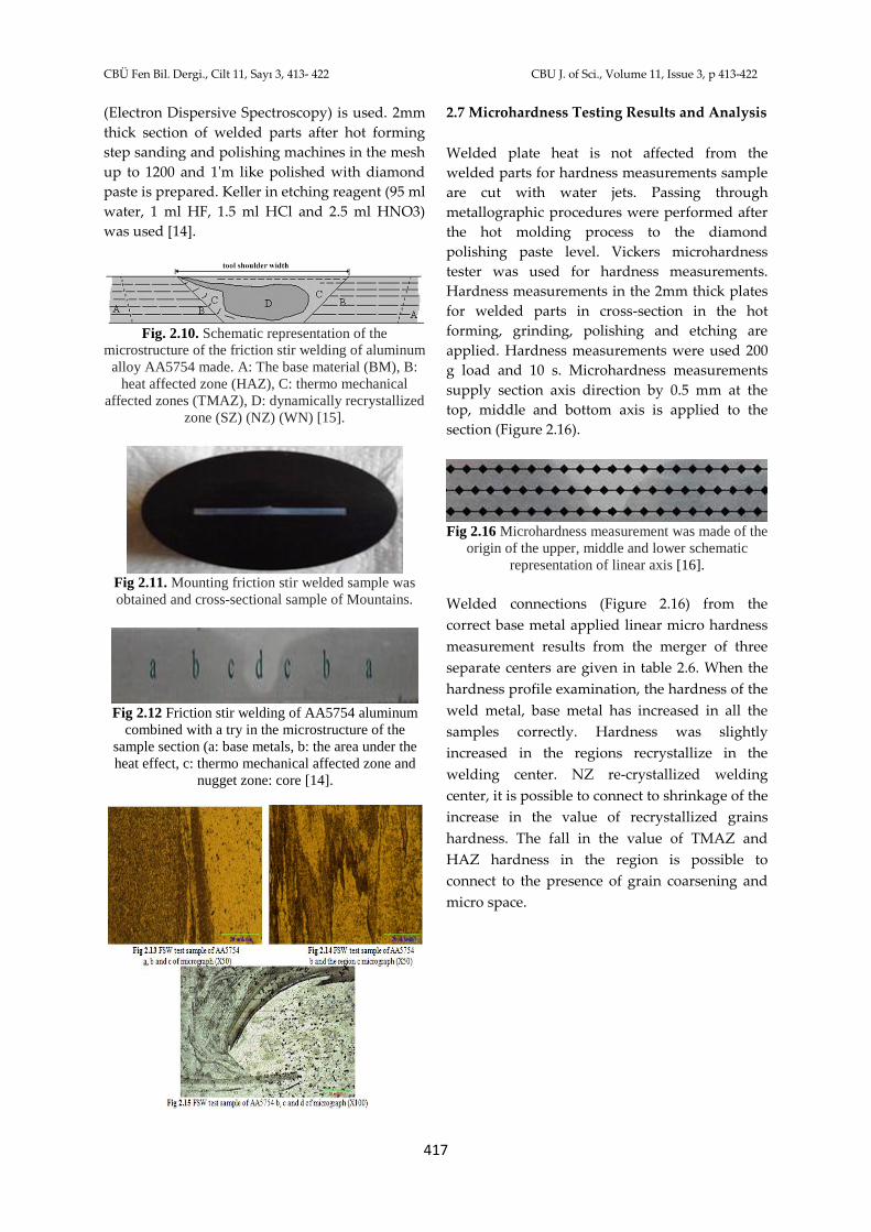
Fig. 2.10. Schematic representation of the
microstructure of the friction stir welding of aluminum
alloy AA5754 made. A: The base material (BM), B:
heat affected zone (HAZ), C: thermo mechanical
affected zones (TMAZ), D: dynamically recrystallized
zone (SZ) (NZ) (WN) [15].
Fig 2.11. Mounting friction stir welded sample was
obtained and cross-sectional sample of Mountains.
Fig 2.12 Friction stir welding of AA5754 aluminum
combined with a try in the microstructure of the
sample section (a: base metals, b: the area under the
heat effect, c: thermo mechanical affected zone and
nugget zone: core [14].
2.7 Microhardness Testing Results and Analysis
Welded plate heat is not affected from the
welded parts for hardness measurements sample
are cut with water jets. Passing through
metallographic procedures were performed after
the hot molding process to the diamond
polishing paste level. Vickers microhardness
tester was used for hardness measurements.
Hardness measurements in the 2mm thick plates
for welded parts in cross-section in the hot
forming, grinding, polishing and etching are
applied. Hardness measurements were used 200
g load and 10 s. Microhardness measurements
supply section axis direction by 0.5 mm at the
top, middle and bottom axis is applied to the
section (Figure 2.16).
Fig 2.16 Microhardness measurement was made of the
origin of the upper, middle and lower schematic
representation of linear axis [16].
Welded connections (Figure 2.16) from the
correct base metal applied linear micro hardness
measurement results from the merger of three
separate centers are given in table 2.6. When the
hardness profile examination, the hardness of the
weld metal, base metal has increased in all the
samples correctly. Hardness was slightly
increased in the regions recrystallize in the
welding center. NZ re-crystallized welding
center, it is possible to connect to shrinkage of the
increase in the value of recrystallized grains
hardness. The fall in the value of TMAZ and
HAZ hardness in the region is possible to
connect to the presence of grain coarsening and
micro space.

CBÜ Fen Bil. Dergi., Cilt 11, Sayı 3, 413- 422 CBU J. of Sci., Volume 11, Issue 3, p 413-422
418
Table 2.6 Hardness values are taken from the Welding
cross-section
Table 2.7 The tool with the friction stir welding
method 1600 rev/min rotation and 125 mm/ min
with a feed rate of the welded plates created (ASTM
E8M-04) cut to the appropriate standard tensile stress-
strain results obtained from samples
Fig 2.17 1600 rev/min rotation and 125
mm/min feed rate to the top of the line joining
the welding made from the cross-sectional area,
a graphical representation of the upper, middle
and lower axis.
Fig 2.18 Friction stir welding of the lead with 1600
rev/min rotation and 125 mm/min advance speed of
the welded sheet formed (ASTM E8M-04) obtained
according to standard tensile samples cut from the
stress-strain graph.
Fig 2.19 Tensile specimen after fracture; the FSW
accomplished at tool rotational velocity of 1600 rpm,
tool traverse speed of 125 mm/min (ASTM E8M-04).
2.8 The tool with the friction stir welding
method 1600 rev/min rotation and 125 mm/min
with a feed rate of the welded plates created
(ASTM E8M-04) obtained from samples cut
tensile stress-strain analysis according to
standards
When the macro photo surface, flat and smooth
surface that take place any sources of error seems
to be obtained (Figure 2.6,2.7,2.8,2.9). Figure 2.18
at 125 mm / min table feed source combined with
parameters coded R1 is seen drawing curves of
welded joints. R1 coded true stress-strain curve
of the welded sample is given in Figure
2.18.Tensile test results of samples (TMAZ)
ductile damage occurring species in the region
are shown in Figure 2.19. When the light
microscope micrograph taken through the weld
in Figure 2.13,2.14,2.15 are examined, it is seen
that there are any gaps on the surface and
unconnected areas.R1 coded tensile pull test
samples stored in the sample-elongation values
are given in Table 2.7. Tensile strength and
elongation values when analyzed average 192.37
N / mm2 is clear that the numerical values
exhibited ductile behavior. 2.13,2.14,2.15 the
mixing zone as shown in Figure (d) is fine-
grained structure with small thermo-

CBÜ Fen Bil. Dergi., Cilt 11, Sayı 3, 413- 422 CBU J. of Sci., Volume 11, Issue 3, p 413-422
419
mechanically affected zone (b, c) is composed of
more coarse and recrystallization rated one.
Constant 1600 rev / min rotation and 125 mm /
min table feed rate using the combined R1 coded
fracture surfaces of samples are examined, it is
again the crystallization, the grain coarsening
and the micro-cavities (TMAZ) rupture zones
have occurred (Figure 2.19).As it is shown in
Figure 2.13,2.14,2.15 (a, b, c) source zones and the
thermo-mechanically affected zone (TMAZ)
transition area between the observed markedly.
In micrographs obtained by light microscopy it
was determined that forming void of
amalgamation of limits on AA5754
aluminum.The welded specimens were produced
by employing a constant tool traverse speed of
125 mm/min and rotating speed of 1600 rpm
yielded a maximum tensile strength of 196 MPa
which was 84% of the base material strength.
Fig.2.20 Scanning electron micrographs obtained from
AA5754 base Metal (BM).
Fig.2.21 Scanning electron microscope (SEM) EDS
spectrum of AA5754 Base metal (BM).
Table 2.8 Chemical composition of AA5754 Base
metal(BM)
Fig.2.22 Scanning electron micrograph image in the
HAZ, TMAZ and SZ of friction stir weld of AA5754
alloys showing recrystallized grains with re-
precipitated intermetallic different in size and
distribution compared with the intermetallic in the
parent metals.
Fig.2.23 Scanning electron microscope (SEM) in EDS
spectrum of the HAZ, TMAZ and SZ.
Table 2.9 Chemical composition of in the TMAZ and
SZ
2.9 Corrosıon Measurement of FSWed AA5754
Aluminium Alloy Sheets
Galvanostat / potentiostat (Gamry model
PC4/300) was used for corrosion test. A three-
electrode system was employed which was
CBÜ Fen Bil. Dergi., Cilt 11, Sayı 3, 413- 422 CBU J. of Sci., Volume 11, Issue 3, p 413-422
420
composed of a counter electrode of carbon rod, a
reference electrode of saturated calomel electrode
(SCE) and a work electrode of tested sample
(square cube shape samples with an average size
of 2 mm x 2 mm). During electrochemical
corrosion test, the electrode potential was
scanned at a scan rate of 1 mV/min from -1000
mV towards anodic potential and the corrosion
current values were recorded in 1 mV steps for
both anodic and cathodic polarization in the unit
of A/cm2 by dividing the current values of the
each sample by their initial total surface area
(Figure 2.24).
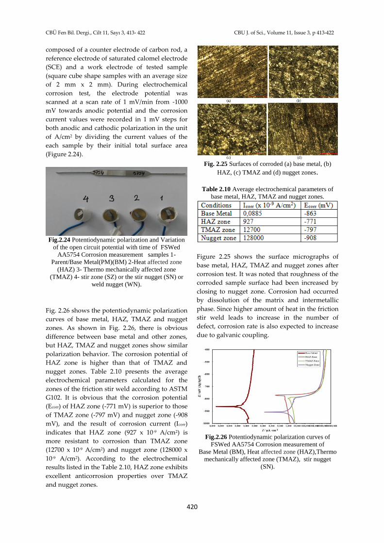
Fig.2.24 Potentiodynamic polarization and Variation
of the open circuit potential with time of FSWed
AA5754 Corrosion measurement samples 1-
Parent/Base Metal(PM)(BM) 2-Heat affected zone
(HAZ) 3- Thermo mechanically affected zone
(TMAZ) 4- stir zone (SZ) or the stir nugget (SN) or
weld nugget (WN).
Fig. 2.26 shows the potentiodynamic polarization
curves of base metal, HAZ, TMAZ and nugget
zones. As shown in Fig. 2.26, there is obvious
difference between base metal and other zones,
but HAZ, TMAZ and nugget zones show similar
polarization behavior. The corrosion potential of
HAZ zone is higher than that of TMAZ and
nugget zones. Table 2.10 presents the average
electrochemical parameters calculated for the
zones of the friction stir weld according to ASTM
G102. It is obvious that the corrosion potential
(Ecorr) of HAZ zone (-771 mV) is superior to those
of TMAZ zone (-797 mV) and nugget zone (-908
mV), and the result of corrosion current (Icorr)
indicates that HAZ zone (927 x 10-9 A/cm2) is
more resistant to corrosion than TMAZ zone
(12700 x 10-9 A/cm2) and nugget zone (128000 x
10-9 A/cm2). According to the electrochemical
results listed in the Table 2.10, HAZ zone exhibits
excellent anticorrosion properties over TMAZ
and nugget zones.
Fig. 2.25 Surfaces of corroded (a) base metal, (b)
HAZ, (c) TMAZ and (d) nugget zones.
Table 2.10 Average electrochemical parameters of
base metal, HAZ, TMAZ and nugget zones.
Figure 2.25 shows the surface micrographs of
base metal, HAZ, TMAZ and nugget zones after
corrosion test. It was noted that roughness of the
corroded sample surface had been increased by
closing to nugget zone. Corrosion had occurred
by dissolution of the matrix and intermetallic
phase. Since higher amount of heat in the friction
stir weld leads to increase in the number of
defect, corrosion rate is also expected to increase
due to galvanic coupling.
Fig.2.26 Potentiodynamic polarization curves of
FSWed AA5754 Corrosion measurement of
Base Metal (BM), Heat affected zone (HAZ),Thermo
mechanically affected zone (TMAZ), stir nugget
(SN).
CBÜ Fen Bil. Dergi., Cilt 11, Sayı 3, 413- 422 CBU J. of Sci., Volume 11, Issue 3, p 413-422
421
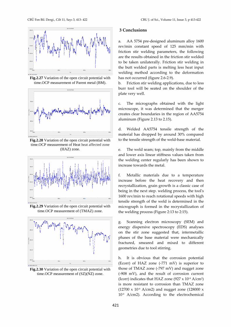
Fig.2.27 Variation of the open circuit potential with
time.OCP measurement of Parent metal (BM).
Fig.2.28 Variation of the open circuit potential with
time.OCP measurement of Heat heat affected zone
(HAZ) zone.
Fig.2.29 Variation of the open circuit potential with
time.OCP measurement of (TMAZ) zone.
Fig.2.30 Variation of the open circuit potential with
time.OCP measurement of (SZ)(NZ) zone.
3 Conclusions
a. AA 5754 pre-designed aluminum alloy 1600
rev/min constant speed of 125 mm/min with
friction stir welding parameters, the following
are the results obtained in the friction stir welded
to be taken unilaterally. Friction stir welding in
the butt welded parts is melting less heat input
welding method according to the deformation
has not occurred (figure 2.6-2.9).
b. Friction stir welding applications, due to less
burr tool will be seated on the shoulder of the
plate very well.
c. The micrographs obtained with the light
microscope, it was determined that the merger
creates clear boundaries in the region of AA5754
aluminum (Figure 2.13 to 2.15).
d. Welded AA5754 tensile strength of the
material has dropped by around 30% compared
to the tensile strength of the weld-base material.
e. The weld seam; top, mainly from the middle
and lower axis linear stiffness values taken from
the welding center regularly has been shown to
increase towards the metal.
f. Metallic materials due to a temperature
increase before the heat recovery and then
recrystallization, grain growth is a classic case of
being in the next step. welding process, the tool's
1600 rev/min to reach rotational speeds with high
tensile strength of the weld is determined in the
micrograph is formed in the recrystallization of
the welding process (Figure 2:13 to 2:15).
g. Scanning electron microscopy (SEM) and
energy dispersive spectroscopy (EDS) analyses
on the stir zone suggested that, intermetallic
phases of the base material were mechanically
fractured, smeared and mixed to different
geometries due to tool stirring.
h. It is obvious that the corrosion potential
(Ecorr) of HAZ zone (-771 mV) is superior to
those of TMAZ zone (-797 mV) and nugget zone
(-908 mV), and the result of corrosion current
(Icorr) indicates that HAZ zone (927 x 10-9 A/cm2)
is more resistant to corrosion than TMAZ zone
(12700 x 10-9 A/cm2) and nugget zone (128000 x
10-9 A/cm2). According to the electrochemical
CBÜ Fen Bil. Dergi., Cilt 11, Sayı 3, 413- 422 CBU J. of Sci., Volume 11, Issue 3, p 413-422
422
results listed in the Table 2.10, HAZ zone exhibits
excellent anticorrosion properties over TMAZ
and nugget zones.
4 Acknowledgements
Asst.Prof.Dr.SAMUR acknowledges the support
by Marmara University, Scientific Research
Projects Department(BAPKO),Projects FEN-D-
110815-0396 and FEN-C-YLP-030114-0014.The
authors also acknowledge the SEM operator
Mr.Semih ÖZBEY of Department of Materials
and Metallurgy, Faculty of Technology, Marmara
University.
Note: The responsible translator for English
language is O. Faruk CANTEKİN, School of
Foreign Languages, Gazi University, Turkey
5 References
[1] Khan, N.Z.; Siddiquee, A.N.; Khan, Z.A.; Shihab,
S.K. Investigations on tunneling and kissing bond
defects in FSW joints for dissimilar aluminum alloys.
Journal of Alloys and Compounds. 2015; 648, 360-367.
[2] Fonda, R.W.; Pao, P.S.; Jones, H.N.; Feng, C.R.
Microstructure, mechanical properties, and corrosion
of friction stir welded Al 5456. Materials Science and
Engineering A. 2009; 519, 1–8.
[3] Shen, C.; Zhang, J.; Ge, J. Microstructures and
lectrochemical behaviors of the friction stir welding
dissimilar weld. Journal of Environmental Sciences
2011; 23, 32–S35.
[4] Threadgill, P L. Terminology in friction stir
welding. Science and Technology of Welding and
Joining, 2007; 12(4), 357−360.
[5] Kannan, M.B.; Srinivasan, P.B.; Raja, V.S. Stress
corrosion cracking (SCC). A volume in Woodhead
Publishing Series in Metals and Surface Engineering
2011; 307–340.
[6] Kalita, S.J. Microstructure and corrosion properties
of diode laser melted friction stir weld of aluminum
alloy 2024 T351. Applied Surface Science. 2011; 257,
3985–3997.
[7] Park, S.H. Corrosion and optimum corrosion
protection potential of friction stir welded 5083-O Al
alloy for leisure ship. Trans. Nonferrous Met. Soc.
China. 2009; 19, 898-903.
[8] Jonckheere, C.; de Meester, B.; Denquin, A.; Simar,
A. Torque, temperature and hardening precipitation
evolution in dissimilar friction stir welds between
6061-T6 and 2014-T6 aluminum alloys. Journal of
Materials Processing Technology. 2013; 213, 826– 837.
[9] Paglia, C.S.; Buchheit, R.G. A look in the corrosion
of aluminum alloy friction stir welds. Scripta
Materialia. 2008; 58, 383–387.
[10] Steuwer, A.; Peel, M. J.; Withers, P.J. Dissimilar
Friction Stir Welds in AA5083–AA6082: The Effect of
Process Parameters on Residual Stress. Materials
Science and Engineering A. 2006; 441, 187–196.
[11] Wang, Q., Zhao, Y.; Yan, K.; Lu, S. Corrosion
behavior of spray formed 7055 aluminum alloy joint
welded by underwater friction stir welding. Materials
and Design. 2015; 68, 97–103.
[12] Sato, Y.S.; Kurihara, Y.; Park, S.H.C.; Kokawa, H.;
Tsuji, N. Friction Stir Welding Of Ultrafine Grained Al
Alloy 1100 Produced by Accumulative Rollbonding.
Scripta Materialia. 2004; 50, 57-60.
[13] Elangovan, K.; Balasubramanian, V. Influences of
tool pin profile and welding speed on the formation of
friction stir processing zone in AA2219 aluminium
alloy. Journal of Materials Processing Technology,
2000; 200, 163–175.
[14] Doğan, S. AA 5754-H22, Alüminyum
Alaşımının Sürtünme Karıştırma Kaynağında İşlem
Parametrelerinin Mikroyapı Ve Mekanik Özelliklere
Etkileri, Yüksek Lisans Tezi, Metalürji Mühendisliği
Anabilim Dalı, Osmangazi Üniversitesi Fen Bilimleri
Enstitüsü, Ekim 2006.
[15] Bradley, G.R.; Jones, M.N. Geometry and
Microstructure of metal inert gas and friction stir
welded Aluminium Alloy. 2000; 5383-H321, 86p.
[16] Şık, A.; Ertürk, İ.; Önder, M., AA2024 Alüminyum
Alaşımının Sürtünme Karıştırma Kaynağında Farklı
Parametrelerin Mekanik Özelliklere Etkisinin
İncelenmesi, Pamukkale Üniversitesi Mühendislik
Bilimleri Dergisi. 2010, 16(2), 139-147.