implementation of active and passive control … · implementation of active and passive control...
TRANSCRIPT
IMPLEMENTATION OF ACTIVE AND PASSIVE CONTROL SYSTEM S IN LABORATORIAL AND REAL STRUCTURES
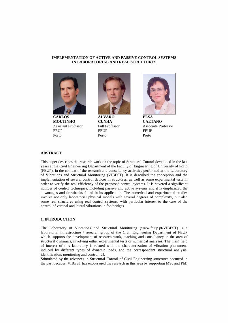
CARLOS MOUTINHO Assistant Professor FEUP Porto
ÁLVARO CUNHA Full Professor FEUP Porto
ELSA CAETANO Associate Professor FEUP Porto
ABSTRACT This paper describes the research work on the topic of Structural Control developed in the last years at the Civil Engineering Department of the Faculty of Engineering of University of Porto (FEUP), in the context of the research and consultancy activities performed at the Laboratory of Vibrations and Structural Monitoring (VIBEST). It is described the conception and the implementation of several control devices in structures, as well as some experimental tests in order to verify the real efficiency of the proposed control systems. It is covered a significant number of control techniques, including passive and active systems and it is emphasized the advantages and drawbacks found in its application. The numerical and experimental studies involve not only laboratorial physical models with several degrees of complexity, but also some real structures using real control systems, with particular interest to the case of the control of vertical and lateral vibrations in footbridges. 1. INTRODUCTION The Laboratory of Vibrations and Structural Monitoring (www.fe.up.pt/VIBEST) is a laboratorial infrastructure / research group of the Civil Engineering Department of FEUP which supports the development of research work, teaching and consultancy in the area of structural dynamics, involving either experimental tests or numerical analyses. The main field of interest of this laboratory is related with the characterization of vibration phenomena induced by different types of dynamic loads, and the correspondent structural analysis, identification, monitoring and control [2]. Stimulated by the advances in Structural Control of Civil Engineering structures occurred in the past decades, VIBEST has encouraged the research in this area by supporting MSc and PhD
students in the study and development of control systems to reduce undesirable vibrations in several types of structures, like building floors, building frames, walkways and footbridges. As a result, many laboratorial control systems were developed using different techniques, e.g., passive systems using tuned mass dampers and tuned liquid dampers, and active systems based on active mass dampers or active bracing systems. Complementary to this area, VIBEST has an important role in the field of consultancy to different entities, such as structural designers, construction companies, national transport agencies and production industries, giving scientific support in the several areas of structural dynamics including assessment, control and monitoring of vibrations in Civil Engineering structures. Recently, it was involved in the analysis and control of vibrations in “Pedro e Inês” footbridge located at Coimbra, which was designed by the well known Portuguese designer António Adão da Fonseca in collaboration with Cecil Balmond from ARUP. In this case, passive tuned mass dampers were installed to reduce vertical and lateral vibrations of the deck. In this context, next sections describe the most representative implementations of control systems developed by VIBEST applied to laboratorial models and to real structures. 2. ACTIVE SYSTEMS 2.1 Context of the research Active systems have been widely used to control vibrations in Civil Engineering structures, particularly in Japan where, until the first years of this decade, more than 50 buildings were endowed with this kind of devices [4]. Active control is the most powerful type of control system because it allows achieving high levels of efficiency in the reduction of vibrations by applying at each instant an adequate control force to the structure. Active control allows controlling simultaneously several vibration modes with a single device which makes this system an interesting solution to reduce the response of flexible low-damped structures characterized by having several vibration modes contributing significantly to global dynamics [3]. Moreover, active systems are versatile, don’t have tuning problems and can be unconditionally stable by adopting collocated control [9]. However, active control may not be an attractive solution in terms of cost because it requires a higher level of technology and maintenance than other control systems, and demands frequently large control devices and power supply systems[11]. In addition, active systems also have problems in terms of reliability because they may be ineffective in certain circumstances. In this context, the research on this topic had the objective to study and implement active control systems in plane frame physical models of 1 and 3 floors and in a real footbridge, in order to verify experimentally the efficiency achieved. It was also aimed to acquire knowledge and experience in the real implementation of such systems which involves working with electronic equipments, mechanical actuators and instrumentation, as well as control hardware and software. 2.2 Active Mass Dampers One of the most well known actuators used to apply forces to mechanical systems are the Active Mass Dampers (AMDs) because they can be positioned in the most favourable positions in terms of the modal components of the significant vibration modes and can be easily hidden
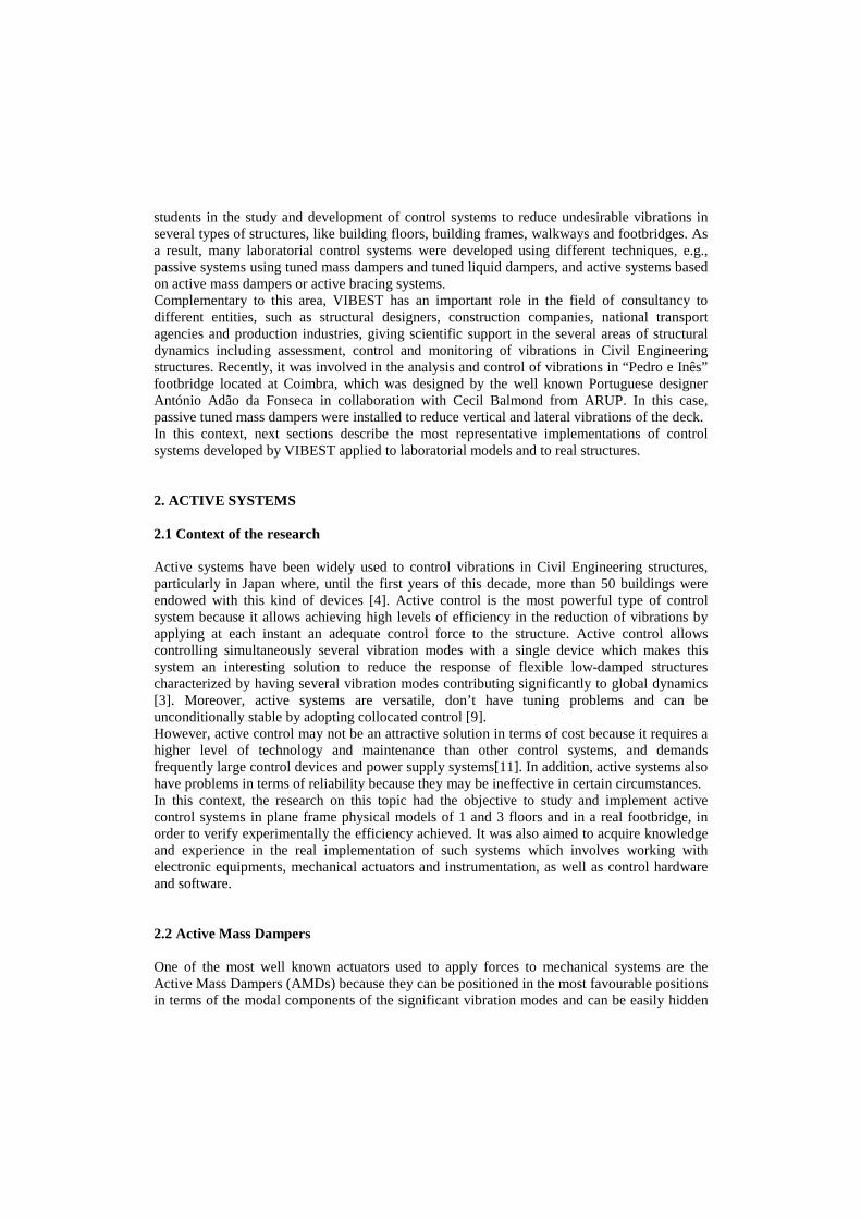
inside the structure. This kind of device was used in a first experience involving the reduction of vibrations in a small frame subjected to different type of loads, like seismic, harmonic and impulsive forces. Figure 1a) shows the experimental setup related to the excitation of a physical model with seismic and harmonic loads induced by a small shaking table and Figure 1b) shows the hammer used to apply impulsive forces at the top of the frame. In this last case, it was possible to increase the damping coefficient of the system from 0.5% to 4.5%, conducting to the free vibration response shown in Figure 1c) [5].
(b)
(a)
-0.15
-0.10
-0.05
0.00
0.05
0.10
0.15
0 0.5 1 1.5 2 2.5 3 3.5 4
t(s)
acce
lera
tio
n (
g)
(c)
Figure 1: a) Physical model mounted on a shaking table; b) Small impulse hammer; c) System response to impulsive loads
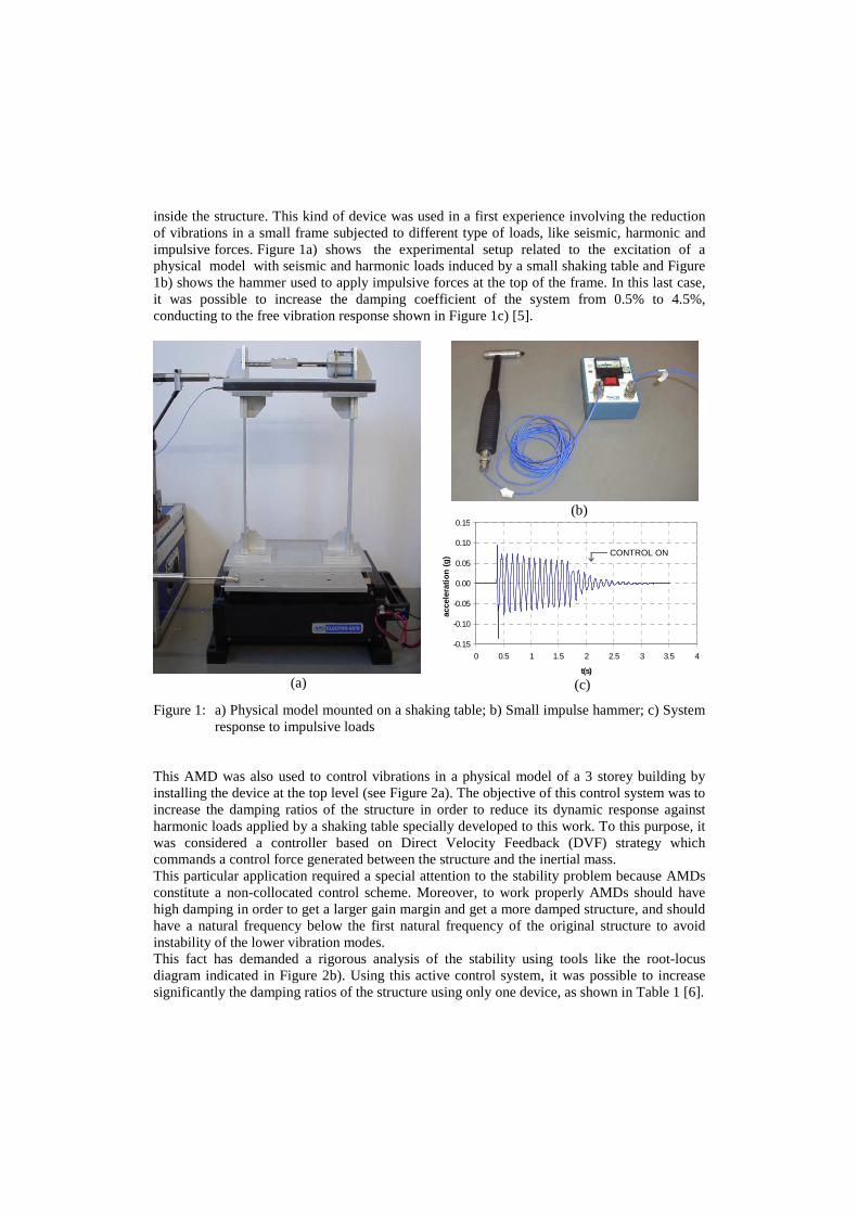
This AMD was also used to control vibrations in a physical model of a 3 storey building by installing the device at the top level (see Figure 2a). The objective of this control system was to increase the damping ratios of the structure in order to reduce its dynamic response against harmonic loads applied by a shaking table specially developed to this work. To this purpose, it was considered a controller based on Direct Velocity Feedback (DVF) strategy which commands a control force generated between the structure and the inertial mass. This particular application required a special attention to the stability problem because AMDs constitute a non-collocated control scheme. Moreover, to work properly AMDs should have high damping in order to get a larger gain margin and get a more damped structure, and should have a natural frequency below the first natural frequency of the original structure to avoid instability of the lower vibration modes. This fact has demanded a rigorous analysis of the stability using tools like the root-locus diagram indicated in Figure 2b). Using this active control system, it was possible to increase significantly the damping ratios of the structure using only one device, as shown in Table 1 [6].
CONTROL ON
0-10-20-30-40-50-60-70 10-80
-100
-150
-50
0
50
100
150
0.050.110.170.240.340.46
0.62
0.84
Real axis
Imag
axi
s
20
40
60
80
100
120
140
20
0.24
0.62
0.84
0.46 0.34
100
60
40
80
0.110.17140
0.05120
1st mode
2nd mode
3rd mode
4th mode
(AMD mode)
Figure 2: a) Experimental setup of a 3 storey model controlled by an AMD; b) Root-locus diagram
Table 1: Damping ratios of the structure with and without control Damping ratio (%)
Mode Frequency without control with control
1 5.50 3.20 - 2 7.35 1.80 7.09 3 15.50 0.35 1.44 4 22.50 0.22 0.44
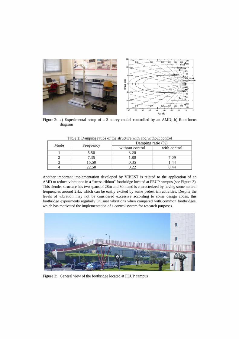
Another important implementation developed by VIBEST is related to the application of an AMD to reduce vibrations in a “stress-ribbon” footbridge located at FEUP campus (see Figure 3). This slender structure has two spans of 28m and 30m and is characterized by having some natural frequencies around 2Hz, which can be easily excited by some pedestrian activities. Despite the levels of vibration may not be considered excessive according to some design codes, this footbridge experiments regularly unusual vibrations when compared with common footbridges, which has motivated the implementation of a control system for research purposes.
Figure 3: General view of the footbridge located at FEUP campus

After some numerical studies about the design of the control system [5], it was decided to perform in-field tests using an AMD existing at VIBEST composed by an active mass of 34kg. Despite the very low mass ratio between the AMD mass and the modal mass of the structure (about 0.15%), it was still possible to achieve nice performance of the control system in damping some vibration modes. For example, Figure 4a) shows the case where a pedestrian excited the structure by walking in resonance with the natural frequency of 2.4Hz, considering both situations of having the control system switched on and off. It is possible to see in Figure 4b) the effect of the control force, which allowed to reduce significantly the structural response from 0.30m/s2 to 0.19m/s2 corresponding to an increase of the damping ratio of the vibration mode from 1.76% to 4.15% [7].
Figure 4: a) Pedestrian walking in resonance with the structure; b) Response with and without control
2.3 Active Bracing systems The 3 storey physical model described before was also submitted to a control experience using an active bracing system to reduce vibrations induced by a shaking table (see Figure 5). The device, composed by a “voice coil motor” and a diagonal brace, was installed at the 1st level. The system response was measured by non-contact displacement sensors located at each floor with the help of a lateral tower.
Figure 5: Plane frame physical model using an active bracing system
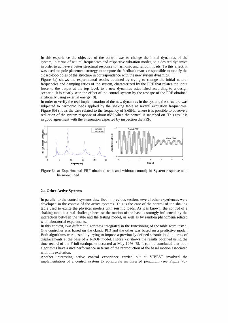
In this experience the objective of the control was to change the initial dynamics of the system, in terms of natural frequencies and respective vibration modes, to a desired dynamics in order to achieve a better structural response to harmonic and random loads. To this effect, it was used the pole placement strategy to compute the feedback matrix responsible to modify the closed-loop poles of the structure in correspondence with the new system dynamics. Figure 6a) shows the experimental results obtained by trying to change the initial natural frequencies and damping ratios of the system, characterized by the FRF that relates the input force to the output at the top level, to a new dynamics established according to a design scenario. It is clearly seen the effect of the control system by the reshape of the FRF obtained artificially using external energy [8]. In order to verify the real implementation of the new dynamics in the system, the structure was subjected to harmonic loads applied by the shaking table at several excitation frequencies. Figure 6b) shows the case related to the frequency of 8.65Hz, where it is possible to observe a reduction of the system response of about 85% when the control is switched on. This result is in good agreement with the attenuation expected by inspection the FRF.
0
0.1
0.2
0.3
0.4
0 5 10 15 20 25
Frequency (Hz)
FRF
am
plit
ude
((m
/s2)
/N) With control
Without control
-1.5
0
1.5
0 1 2 3 4 5 6
Time (s)
Acc
eler
atio
n (
m/s
2)
Control OFF
Control ON
Figure 6: a) Experimental FRF obtained with and without control; b) System response to a harmonic load
2.4 Other Active Systems In parallel to the control systems described in previous section, several other experiences were developed in the context of the active systems. This is the case of the control of the shaking table used to excite the physical models with seismic loads. As it is known, the control of a shaking table is a real challenge because the motion of the base is strongly influenced by the interaction between the table and the testing model, as well as by random phenomena related with laboratorial experiments. In this context, two different algorithms integrated in the functioning of the table were tested. One controller was based on the classic PID and the other was based on a predictive model. Both algorithms were tested by trying to impose a previously defined seismic load in terms of displacements at the base of a 1-DOF model. Figure 7a) shows the results obtained using the time record of the Friuli earthquake occurred at May 1976 [5]. It can be concluded that both algorithms have a nice performance in terms of the reproduction of the basal motion associated with this excitation. Another interesting active control experience carried out at VIBEST involved the implementation of a control system to equilibrate an inverted pendulum (see Figure 7b).

Although this system is very different from a civil engineering structure, its implementation requires a solid knowledge in the field of theoretical and experimental control systems. An inverted pendulum is a highly unstable system, which could be converted into a stable one through the implementation of an efficient control algorithm able to modify its initial behaviour to a dynamics of a stable system. This experience also constitutes a non-linear problem, which required the linearization of the equations of motion in order to use the tools traditionally used for control linear systems.
-0.05
-0.03
-0.02
0.00
0.02
0.03
0.05
0 10 20 30 40
t(s)
Dis
pla
cem
ent
(m)
Seismic Record
PID controller
Predict ive cont roller
Figure 7: a) Shaking table responses for 1976 Friuli’s earthquake; b) Inverted pendulum experience
3. PASSIVE SYSTEMS 3.1 Context of the research Passive control techniques are characterized by the implementation of devices in structures that do not require any external energy source to reduce vibrations. This kind of techniques has been widely implemented in Civil Engineering structures with particular emphasis in the area of Earth-quake Engineering [12]. Most passive devices are prepared to deal with forces of high amplitude and have high capacity for dissipation of energy. Furthermore, compared with other techniques, passive control is more interesting in terms of reliability, cost and maintenance. For these reasons, in the process of studding a system to reduce vibrations in a structure, passive control should be considered as the first solution, and just in case this is not effective enough, move to other more sophisticated technique. As main disadvantage, passive systems are generally less efficient than active systems, particularly in situations that require some adaptability of the control force depending on the structural response. Given the high interest in the use of passive systems, some experiences were developed at VIBEST related with this topic. Next sections describe the implementation of passive control techniques applied to laboratorial models using tuned liquid dampers and tuned mass dampers, as well as the implementation of passive tuned mass dampers to control vibrations in a real footbridge located at Coimbra city.
3.2 Tuned liquid dampers
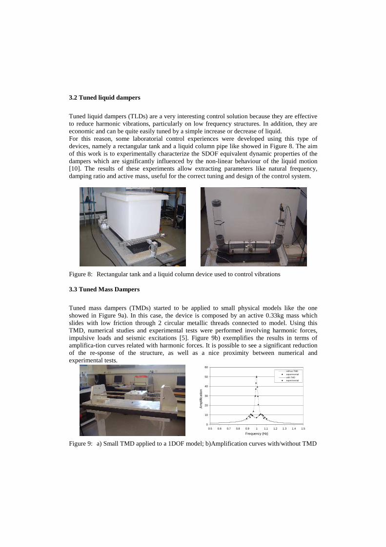
Tuned liquid dampers (TLDs) are a very interesting control solution because they are effective to reduce harmonic vibrations, particularly on low frequency structures. In addition, they are economic and can be quite easily tuned by a simple increase or decrease of liquid. For this reason, some laboratorial control experiences were developed using this type of devices, namely a rectangular tank and a liquid column pipe like showed in Figure 8. The aim of this work is to experimentally characterize the SDOF equivalent dynamic properties of the dampers which are significantly influenced by the non-linear behaviour of the liquid motion [10]. The results of these experiments allow extracting parameters like natural frequency, damping ratio and active mass, useful for the correct tuning and design of the control system.
Figure 8: Rectangular tank and a liquid column device used to control vibrations 3.3 Tuned Mass Dampers
Tuned mass dampers (TMDs) started to be applied to small physical models like the one showed in Figure 9a). In this case, the device is composed by an active 0.33kg mass which slides with low friction through 2 circular metallic threads connected to model. Using this TMD, numerical studies and experimental tests were performed involving harmonic forces, impulsive loads and seismic excitations [5]. Figure 9b) exemplifies the results in terms of amplifica-tion curves related with harmonic forces. It is possible to see a significant reduction of the re-sponse of the structure, as well as a nice proximity between numerical and experimental tests.
0
10
20
30
40
50
60
0.5 0.6 0.7 0.8 0.9 1 1.1 1.2 1.3 1.4 1.5
Frequency (Hz)
Am
plif
ica
tion
without TMD
experimental
with TMDexperimental
Figure 9: a) Small TMD applied to a 1DOF model; b)Amplification curves with/without TMD

The most significant work developed by VIBEST regarding the implementation of TMDs is related with the control of vibrations in “Pedro e Inês” footbridge. This new infrastructure, conceived to become a landmark for the Coimbra city and to contribute to the quality of a new leisure area, was designed by Adão da Fonseca, leading a team from AFAssociados, in collaboration with Cecil Balmond, leading the architectural team from Ove Arup. The bridge has a total length of 275m and is formed by a parabolic central arch with a span of 110m and two half lateral arches, in steel, supporting with total continuity a composite steel-concrete deck (Figure 10). The anti-symmetry of both arch and deck cross-sections along the longitudinal axis of the bridge is a unique feature of this bridge, leading to the creation of a central square with 8mx8m at mid-span.
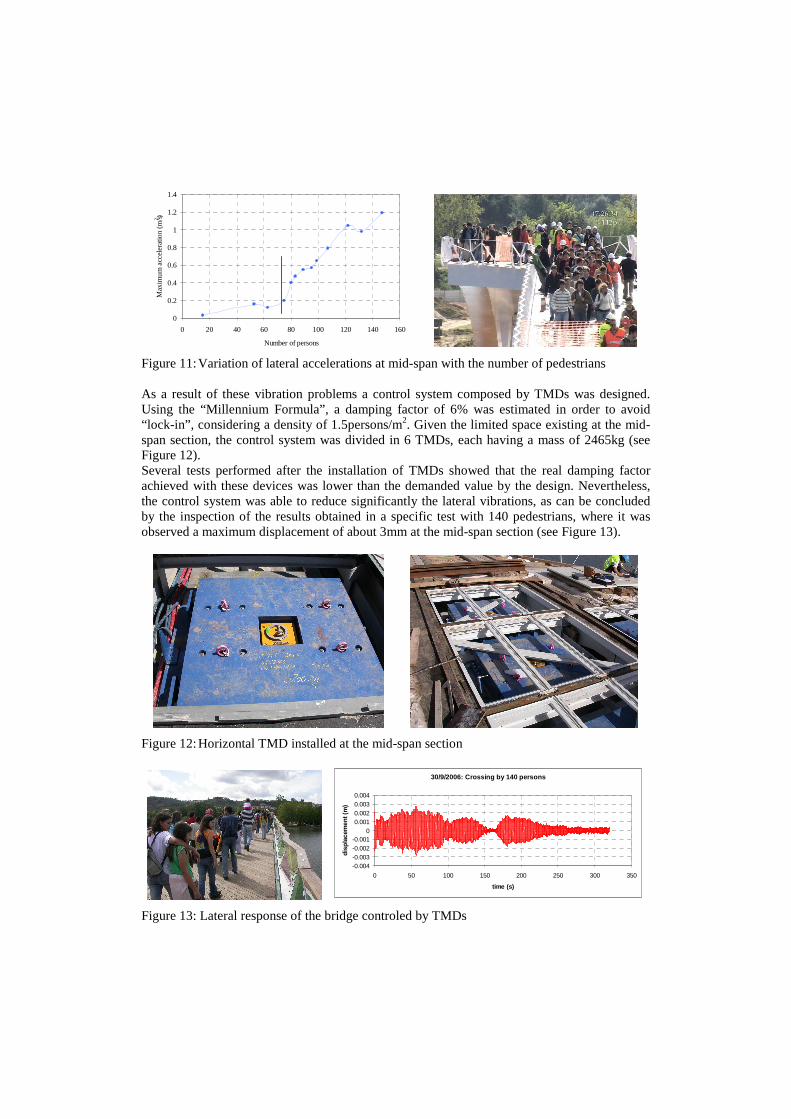
Figure 10: View of the new Coimbra footbridge Preliminary dynamic studies developed by the bridge designers indicated that the bridge would be prone to vibrations induced by pedestrians, requiring control devices. A detailed numerical study was then developed by VIBEST to better characterize the dynamic behaviour of the bridge under pedestrian loads and evaluate the required control measures [1]. This study showed not only that the first lateral mode is critical, owing to the proximity between its estimated natural frequency and the frequency of lateral excitation induced by walking pedestrians, but also that significant levels of vibration may occur when some vertical vibration modes are excited. During the construction stage the footbridge was subjected to some experimental tests involving the identification of the modal properties of the structure, as well as the measurement of vibration levels due to the excitation induced by groups or steam of pedestrians. In this case, a test was developed involving the participation of students from the Universities of Porto and Coimbra. The bridge response was measured to the action of a continuous stream of pedestrians with a gradually increased number to a maximum of 145 persons. These students walked freely along the bridge. Figure 11 shows the variation of the maximum lateral acceleration with the number of pedestrians on the bridge, which allows to conclude that the “lock-in” effect occurs for a number of about 75 persons. At the mid-span section, extreme values of acceleration of ±1.2 m/s2 and of displacement of ±4 cm were recorded when 145 pedestrians were walking on the bridge.
0
0.2
0.4
0.6
0.8
1
1.2
1.4
0 20 40 60 80 100 120 140 160
Number of persons
Max
imu
m a
ccel
erat
ion
(m/s
2)
Figure 11: Variation of lateral accelerations at mid-span with the number of pedestrians As a result of these vibration problems a control system composed by TMDs was designed. Using the “Millennium Formula”, a damping factor of 6% was estimated in order to avoid “lock-in”, considering a density of 1.5persons/m2. Given the limited space existing at the mid-span section, the control system was divided in 6 TMDs, each having a mass of 2465kg (see Figure 12). Several tests performed after the installation of TMDs showed that the real damping factor achieved with these devices was lower than the demanded value by the design. Nevertheless, the control system was able to reduce significantly the lateral vibrations, as can be concluded by the inspection of the results obtained in a specific test with 140 pedestrians, where it was observed a maximum displacement of about 3mm at the mid-span section (see Figure 13).
Figure 12: Horizontal TMD installed at the mid-span section
30/9/2006: Crossing by 140 persons
-0.004-0.003-0.002-0.001
00.0010.0020.0030.004
0 50 100 150 200 250 300 350
time (s)
dis
pla
cem
ent (
m)
Figure 13: Lateral response of the bridge controled by TMDs
4. CONCLUDING REMARKS The Laboratory of Vibrations and Structural Monitoring of FEUP was responsible for the development and implementation of several control systems, particularly active and passive systems. The work in this area involved not only laboratorial physical models, but also included the implementation of control devices in real structures. All these experiments allowed acquiring experience and know-how in the implementation of control systems, which many times go beyond the knowledge necessary to solve the control problem itself. Indeed, it is necessary to fully understand subjects like signal acquisition and processing, the choice of hardware and control software and the choice of instrumentation and actuation systems. Moreover, it is necessary to take into account other practical problems, like non-linearity, time delay in control loop and noise problems in sensors. REFERENCES [1] Caetano, E., Cunha, A. & Moutinho, C. – “Implementation of Passive Devices for
Vibration Control at Coimbra footbridge”, International Conference on Experimental Vibration Analysis for Civil Engineering Structures EVACES'07, Porto, 2007.
[2] Cunha, A., Caetano, E., Magalhães, F. & Moutinho, C. – “Identification , Monitoring and Control of Bridges and Special Structures”, IV ECCOMAS Thematic Conference on Smart Structures and Materials, Porto, 2009.
[3] Fujino, Y. – “Vibration, Control and Monitoring of Long-span Bridges - Recent Research Developments and Practice in Japan”, Journal of Constructional Steel Research, No.58 pp.71-97, 2002.
[4] Ikeda, Y. – “Active and Semi-active Control of Buildings in Japan”, Journal of Japan Association for Earthquake Engineering, Vol.4 No.3, 2004.
[5] Moutinho, C.; Cunha, A.; Caetano, E. – “Implementation of an Active Mass Damper for Seismic Vibration Control of a Plane Frame Physical Model”, 3rd European Conference on Structural Control, Viena, Austria, 2004.
[6] Moutinho, C.; Cunha, A.; Caetano, E. – “Implementation of an Active Damping System to Reduce Harmonic Vibrations in a 3DOF Model”, II ECCOMAS Thematic Conference on Smart Structures and Materials, Lisboa, 2005.
[7] Moutinho, C.; Cunha, A.; Caetano, E. – “Implementation of an Active Mass Damper to Control Vibrations in a ‘Lively’ Footbridge”, III ECCOMAS thematic Conference on Smart Structures and Materials, Gdansk, 2007.
[8] Moutinho, C.; Cunha, A.; Caetano, E. – “Implementation of an Active Bracing System to Reduce Vibrations in a Physical Model Using Pole Placement Strategy”, 4th World Conference on Structural Control and Monitoring, San Diego, 2006.
[9] Preumont, A. – “Vibration Control of Active Structures – An introduction”, Kluwer Academic Publishers, 1997.
[10] Ramos, L. & Cunha, A. – “Experimental Study of a Tuned Liquid Damper With Small Base Dis-placement Amplitudes”, 4th European Conference on Structural Control, St. Petersburg, Russia, 2001, 2008.
[11] Soong, T. – “Active Structural Control – Theory & Practice”, Longman Scientific & Technical, 1990.
[12] Soong, T. & Dargush, G. – “Passive Energy Dissipation Systems in Structural Engineering”, John Wiley & Sons, 1997.