hp xp7 owner guide - h20628. ·...
TRANSCRIPT
HP XP7 Owner Guide
AbstractThis guide describes the operation of XP7 Storage. Topics include a description of the disk array hardware, instructions onhow to manage the disk array, descriptions of the disk array control panel and LED indicators, troubleshooting, and regulatorystatements. The intended audience is a storage system administrator or authorized service provider with independent knowledgeof XP7 Storage and the HP Remote Web Console.
HP Part Number: H6F56-96006Published: May 2014Edition: First
© Copyright 2014 Hewlett-Packard Development Company, L.P.
The information contained herein is subject to change without notice. The only warranties for HP products and services are set forth in the expresswarranty statements accompanying such products and services. Nothing herein should be construed as constituting an additional warranty. HP shallnot be liable for technical or editorial errors or omissions contained herein.Acknowledgements
Microsoft®, Windows®, Windows® XP, and Windows NT® are U.S. registered trademarks of Microsoft Corporation.
Java and Oracle are registered trademarks of Oracle and/or its affiliates.
Export Requirements
You may not export or re-export this document or any copy or adaptation in violation of export laws or regulations.
Without limiting the foregoing, this document may not be exported, re-exported, transferred or downloaded to or within (or to a national residentof) countries under U.S. economic embargo, including Cuba, Iran, North Korea, Sudan, and Syria. This list is subject to change.
This document may not be exported, re-exported, transferred, or downloaded to persons or entities listed on the U.S. Department of CommerceDenied Persons List, Entity List of proliferation concern or on any U.S. Treasury Department Designated Nationals exclusion list, or to parties directlyor indirectly involved in the development or production of nuclear, chemical, biological weapons, or in missile technology programs as specifiedin the U.S. Export Administration Regulations (15 CFR 744).
Warranty
WARRANTY STATEMENT: To obtain a copy of the warranty for this product, see the warranty information website:
http://www.hp.com/go/storagewarranty
Contents1 Introduction...............................................................................................6
XP7 Storage overview...............................................................................................................6Hardware overview...................................................................................................................6
Controller chassis.................................................................................................................9Drive chassis.....................................................................................................................12
Features................................................................................................................................14Scalability.........................................................................................................................15High performance..............................................................................................................17High capacity...................................................................................................................17Connectivity......................................................................................................................17
XP7.............................................................................................................................17Remote Web Console....................................................................................................17
High reliability...................................................................................................................17Non disruptive service and upgrades....................................................................................18Economical and quiet.........................................................................................................18
Specifications.........................................................................................................................18Software features and functions................................................................................................20
2 Functional and operational characteristics....................................................23System architecture overview....................................................................................................23Hardware architecture.............................................................................................................23RAID implementation overview.................................................................................................23
Array groups and RAID levels..............................................................................................24Sequential data striping......................................................................................................25LDEV striping across array groups........................................................................................25
CU Images, LVIs, and Logical Units...........................................................................................26CU images.......................................................................................................................26Logical Volume images.......................................................................................................27Logical Units.....................................................................................................................27
Mainframe operations.............................................................................................................27Mainframe compatibility and functionality.............................................................................27Mainframe operating system support....................................................................................28Mainframe configuration.....................................................................................................28
System option modes, host modes, and host mode options...........................................................28System option modes..........................................................................................................28Host modes and host mode options......................................................................................57
Open systems operations.........................................................................................................57Open systems compatibility and functionality.........................................................................57Open systems host platform support.....................................................................................58Open systems configuration.................................................................................................58
Remote Web Console.............................................................................................................593 System components..................................................................................60
Controller chassis...................................................................................................................60System control panel...............................................................................................................62
DKC Panel Jumpers............................................................................................................63Memory operation..................................................................................................................64Data protection......................................................................................................................65Shared memory......................................................................................................................65Flash storage chassis...............................................................................................................65
XP7 flash module...............................................................................................................65Flash module unit...................................................................................................................66
Contents 3
Flash storage chassis...............................................................................................................67Cache memory......................................................................................................................68System capacities with smart flash modules................................................................................68
4 Power On/Off procedures.........................................................................70Safety and environmental information........................................................................................70Standby mode.......................................................................................................................70Power On/Off procedures.......................................................................................................70
Power On procedures.........................................................................................................70Power Off procedures.........................................................................................................71
Battery backup operations.......................................................................................................72Cache destage batteries.....................................................................................................72Battery life .......................................................................................................................72Long term array storage......................................................................................................73
5 Troubleshooting........................................................................................74Solving problems....................................................................................................................74Service information messages...................................................................................................74C-Track..................................................................................................................................75Insight Remote Support............................................................................................................75Failure detection and reporting process.....................................................................................76
6 System specifications and requirements........................................................78Mechanical specifications........................................................................................................78Electrical specifications............................................................................................................78
Grounding........................................................................................................................80Power connection...............................................................................................................80AC Power - PDU Options.....................................................................................................80
Environmental specifications.....................................................................................................82Heat output and air flow..........................................................................................................83Equipment noise.....................................................................................................................85
7 Support and other resources......................................................................86Contacting HP........................................................................................................................86
Subscription service............................................................................................................86Documentation feedback....................................................................................................86
Related information.................................................................................................................86Conventions for storage capacity values....................................................................................86
A Comparing the XP24000/XP20000 Disk Array and XP7 .............................88Comparison of the XP24000/XP20000 Disk Array and XP7........................................................88
B Regulatory compliance notices...................................................................91Regulatory compliance identification numbers............................................................................91Federal Communications Commission notice..............................................................................91
FCC rating label................................................................................................................91Class A equipment........................................................................................................91Class B equipment........................................................................................................91
Declaration of Conformity for products marked with the FCC logo, United States only.................92Modification.....................................................................................................................92Cables.............................................................................................................................92
Canadian notice (Avis Canadien).............................................................................................92Class A equipment.............................................................................................................92Class B equipment.............................................................................................................92
European Union notice............................................................................................................92Japanese notices....................................................................................................................93
Japanese VCCI-A notice......................................................................................................93Japanese VCCI-B notice......................................................................................................93
4 Contents
Japanese VCCI marking.....................................................................................................93Japanese power cord statement...........................................................................................93
Korean notices.......................................................................................................................93Class A equipment.............................................................................................................93Class B equipment.............................................................................................................94
Taiwanese notices...................................................................................................................94BSMI Class A notice...........................................................................................................94Taiwan battery recycle statement..........................................................................................94
Turkish recycling notice............................................................................................................94Laser compliance notices.........................................................................................................95
English laser notice............................................................................................................95Dutch laser notice..............................................................................................................95French laser notice.............................................................................................................95German laser notice...........................................................................................................96Italian laser notice..............................................................................................................96Japanese laser notice.........................................................................................................96Spanish laser notice...........................................................................................................97
Recycling notices....................................................................................................................97English recycling notice......................................................................................................97Bulgarian recycling notice...................................................................................................98Czech recycling notice........................................................................................................98Danish recycling notice.......................................................................................................98Dutch recycling notice.........................................................................................................98Estonian recycling notice.....................................................................................................99Finnish recycling notice.......................................................................................................99French recycling notice.......................................................................................................99German recycling notice.....................................................................................................99Greek recycling notice......................................................................................................100Hungarian recycling notice...............................................................................................100Italian recycling notice......................................................................................................100Latvian recycling notice.....................................................................................................100Lithuanian recycling notice................................................................................................101Polish recycling notice.......................................................................................................101Portuguese recycling notice...............................................................................................101Romanian recycling notice................................................................................................101Slovak recycling notice.....................................................................................................102Spanish recycling notice...................................................................................................102Swedish recycling notice...................................................................................................102
Battery replacement notices...................................................................................................102Dutch battery notice.........................................................................................................102French battery notice........................................................................................................103German battery notice......................................................................................................103Italian battery notice........................................................................................................104Japanese battery notice....................................................................................................104Spanish battery notice......................................................................................................105
Glossary..................................................................................................106Index.......................................................................................................108
Contents 5
1 IntroductionXP7 Storage overview
XP7 Storage is a high capacity, high performance disk array that offers a wide range of storageand data services, software, logical partitioning, and simplified and unified data replication acrossheterogeneous disk arrays. Its large scale, enterprise class virtualization layer combined with SmartTiers and Thin Provisioning software, delivers virtualization of internal and external storage intoone pool.Using this system, you can deploy applications within a new framework, leverage and add valueto current investments, and more closely align IT with business objectives. XP7 Storage provide thefoundation for matching application requirements to different classes of storage and deliver criticalservices including:
• Business continuity services
• Content management services (search, indexing)
• Non disruptive data migration
• Thin Provisioning
• Smart Tiers
• High availability
• Security services
• I/O load balancing
• Data classification
• File management servicesNew technological advances improve reliability, serviceability and access to disk drives and othercomponents when maintenance is needed. Each component contains a set of LEDs that indicatethe operational status of the component. The system includes new and upgraded software features,including Smart Tiers, and a significantly improved, task oriented version of Remote Web Consolethat is designed for ease of use and includes context sensitive online help. The system documentationhas been changed to a task oriented format that is designed to help you find information quicklyand complete tasks easily.
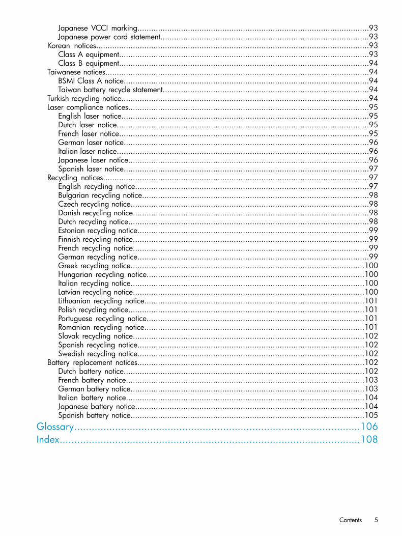
Hardware overviewXP7 Storage contain significant new technology that was not available in previous HP disk arrays.The system can be configured in many ways, starting with a small (one rack) to a large (six rack)system that includes two controller chassis, up to 2304 HDD drives which include up to 384 solidstate drives, and a total of 2048 GB cache. The system provides a highly granular upgrade path,allowing the addition of disk drives to the drive chassis, and Processors Blades and other componentsto the controller chassis in an existing system as storage needs increase. The controller chassis (orDKU) of XP7 Storage can be combined so that what would previously have been two separatedisk arrays are now a single disk array with homogeneous logic control, cache, and front end andback end interfaces, all mounted in custom HP 19 inch racks.Basic XP7 Storage is a control rack (Rack- 00) that contains a controller chassis and two drive (ormedia) chassis (factory designation DKU). Fully configured XP7 Storage consists of two controllerchassis and sixteen drive chassis for fully configured system. The controller chassis contains thecontrol logic, processors, memory, and interfaces to the drive chassis and the host servers. A drivechassis consists of disks or SSD drives, power supplies, and the interface circuitry connecting it tothe controller chassis. The remaining racks (Rack-01, Rack-02, Rack-10 and Rack-11) contain fromone to two drive chassis.
6 Introduction
The following sections provide descriptions and illustrations of XP7 Storage and its components.
Figure 1 HP XP7 Storage (6 rack)
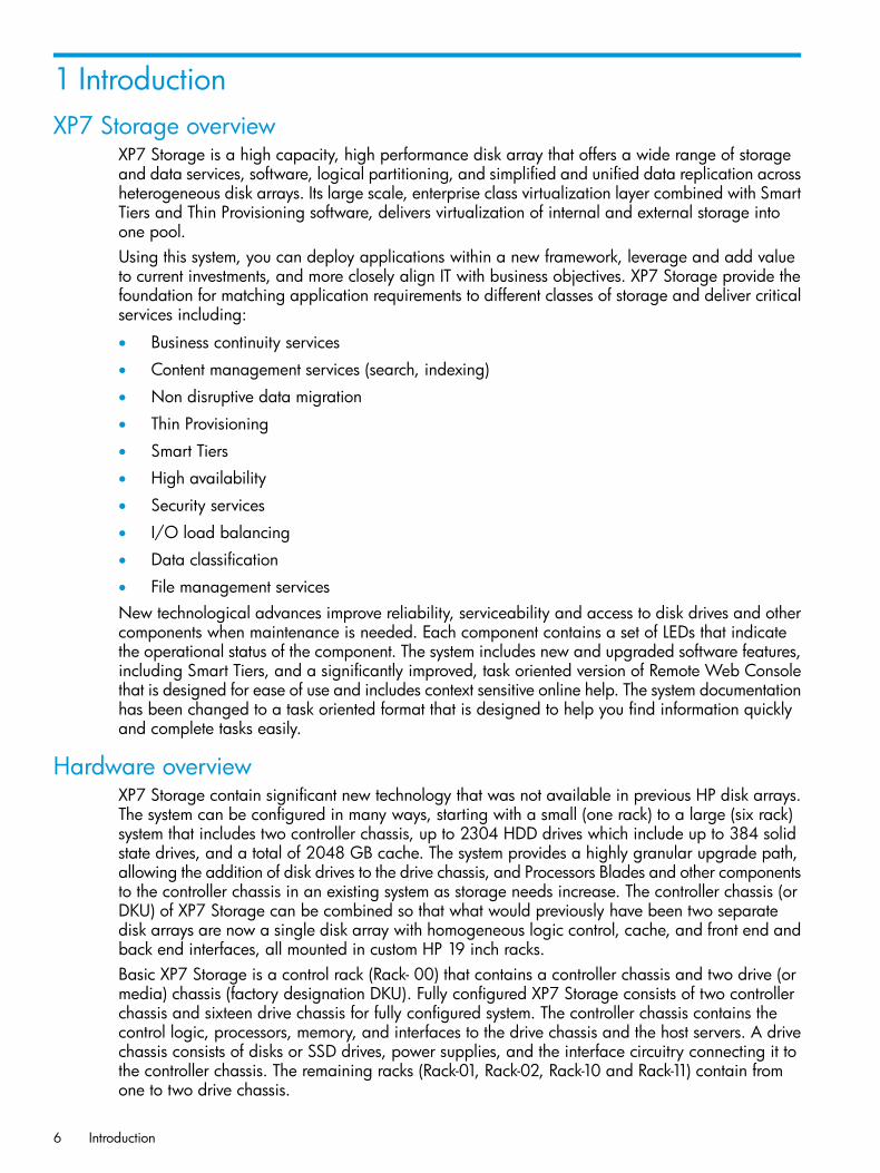
Figure 2 XP7 disk controller rack dimensions
Hardware overview 7
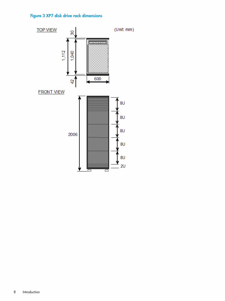
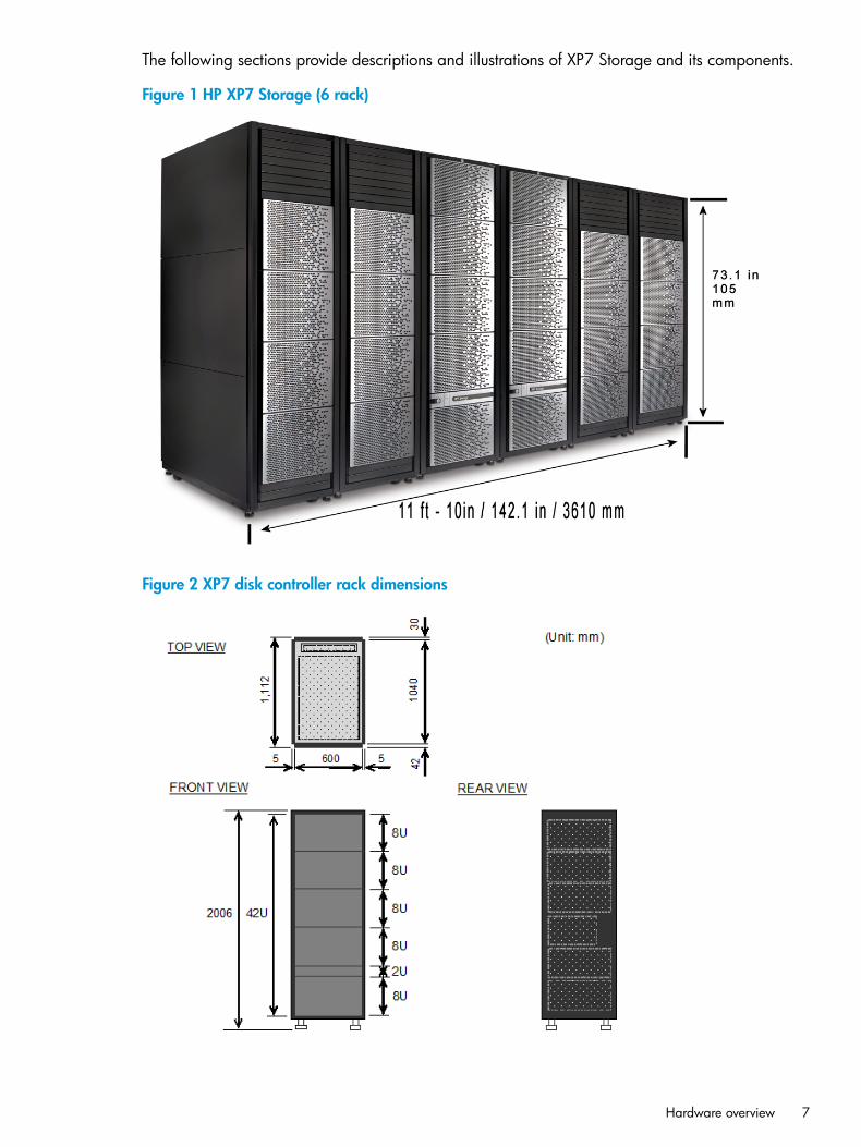
Figure 3 XP7 disk drive rack dimensions
8 Introduction
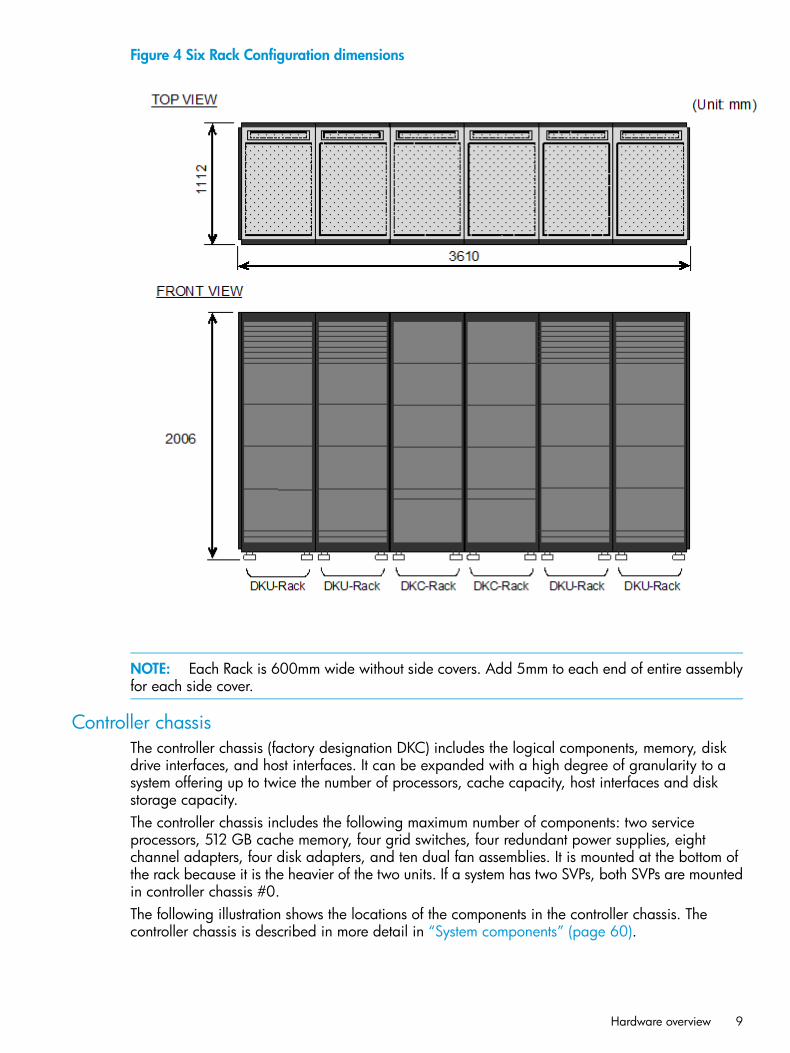
Figure 4 Six Rack Configuration dimensions
NOTE: Each Rack is 600mm wide without side covers. Add 5mm to each end of entire assemblyfor each side cover.
Controller chassisThe controller chassis (factory designation DKC) includes the logical components, memory, diskdrive interfaces, and host interfaces. It can be expanded with a high degree of granularity to asystem offering up to twice the number of processors, cache capacity, host interfaces and diskstorage capacity.The controller chassis includes the following maximum number of components: two serviceprocessors, 512 GB cache memory, four grid switches, four redundant power supplies, eightchannel adapters, four disk adapters, and ten dual fan assemblies. It is mounted at the bottom ofthe rack because it is the heavier of the two units. If a system has two SVPs, both SVPs are mountedin controller chassis #0.The following illustration shows the locations of the components in the controller chassis. Thecontroller chassis is described in more detail in “System components” (page 60).
Hardware overview 9
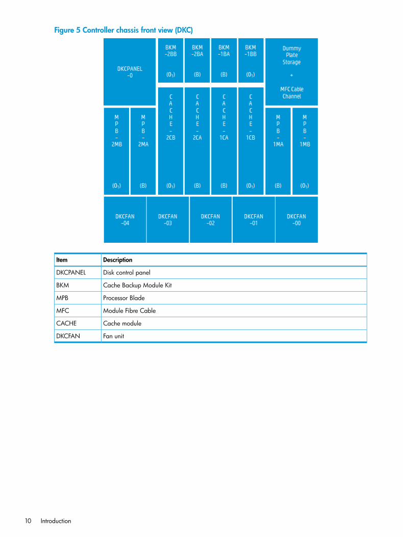
Figure 5 Controller chassis front view (DKC)
DescriptionItem
Disk control panelDKCPANEL
Cache Backup Module KitBKM
Processor BladeMPB
Module Fibre CableMFC
Cache moduleCACHE
Fan unitDKCFAN
10 Introduction
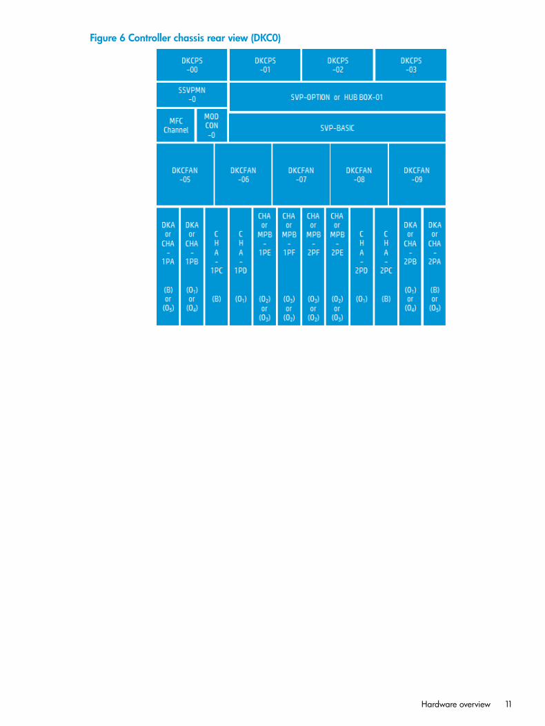
Figure 6 Controller chassis rear view (DKC0)
Hardware overview 11
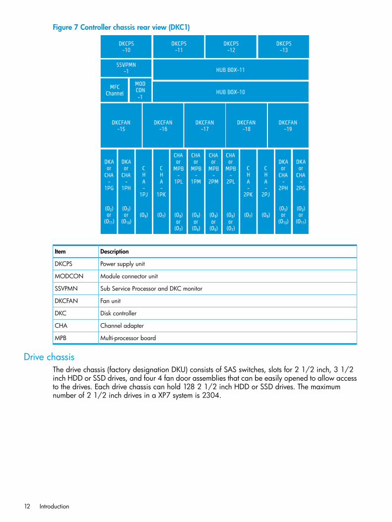
Figure 7 Controller chassis rear view (DKC1)
DescriptionItem
Power supply unitDKCPS
Module connector unitMODCON
Sub Service Processor and DKC monitorSSVPMN
Fan unitDKCFAN
Disk controllerDKC
Channel adapterCHA
Multi-processor boardMPB
Drive chassisThe drive chassis (factory designation DKU) consists of SAS switches, slots for 2 1/2 inch, 3 1/2inch HDD or SSD drives, and four 4 fan door assemblies that can be easily opened to allow accessto the drives. Each drive chassis can hold 128 2 1/2 inch HDD or SSD drives. The maximumnumber of 2 1/2 inch drives in a XP7 system is 2304.
12 Introduction
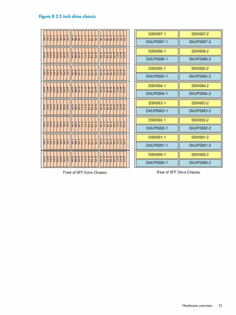
Figure 8 2.5 inch drive chassis
Hardware overview 13
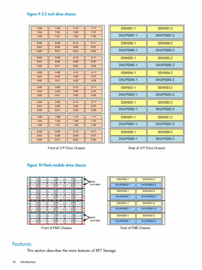
Figure 9 3.5 inch drive chassis
Figure 10 Flash module drive chassis
FeaturesThis section describes the main features of XP7 Storage.
14 Introduction
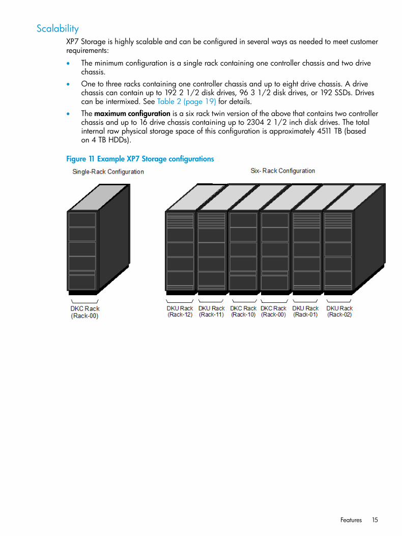
ScalabilityXP7 Storage is highly scalable and can be configured in several ways as needed to meet customerrequirements:
• The minimum configuration is a single rack containing one controller chassis and two drivechassis.
• One to three racks containing one controller chassis and up to eight drive chassis. A drivechassis can contain up to 192 2 1/2 disk drives, 96 3 1/2 disk drives, or 192 SSDs. Drivescan be intermixed. See Table 2 (page 19) for details.
• The maximum configuration is a six rack twin version of the above that contains two controllerchassis and up to 16 drive chassis containing up to 2304 2 1/2 inch disk drives. The totalinternal raw physical storage space of this configuration is approximately 4511 TB (basedon 4 TB HDDs).
Figure 11 Example XP7 Storage configurations
Features 15
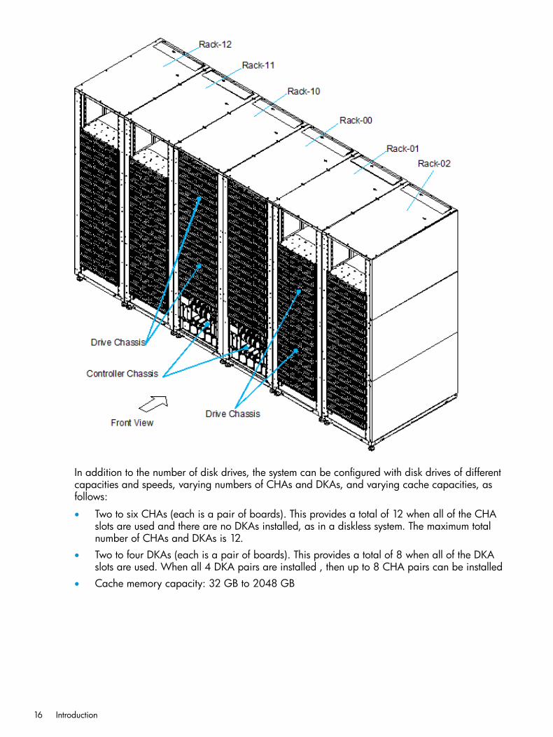
In addition to the number of disk drives, the system can be configured with disk drives of differentcapacities and speeds, varying numbers of CHAs and DKAs, and varying cache capacities, asfollows:
• Two to six CHAs (each is a pair of boards). This provides a total of 12 when all of the CHAslots are used and there are no DKAs installed, as in a diskless system. The maximum totalnumber of CHAs and DKAs is 12.
• Two to four DKAs (each is a pair of boards). This provides a total of 8 when all of the DKAslots are used. When all 4 DKA pairs are installed , then up to 8 CHA pairs can be installed
• Cache memory capacity: 32 GB to 2048 GB
16 Introduction
• Hard Disk drive capacities of 300 GB, 600 GB, 900 GB , 1.2 TB, and 4 TB.
• Solid State Disk Drive capacities of 400 GB, 800 GB.
• Channel ports: 80 for one module, 176 for two modules.
High performanceThe XP7 includes several new features that improve the performance over previous models. Theseinclude:
• 8 GBps only Fibre Channel for CHAs without the limitation of microprocessors on each board.
• SSD flash drives with ultra high speed response.
• High speed data transfer between the DKA and HDDs at a rate of 6 GBps with the SASinterface.
• High speed quad core CPUs that provide three times the performance of an XP24000/XP20000Disk Array.
High capacityThe XP7 supports the following high capacity features:
• HDD (disk) drives with capacities of 300 GB, 600 GB, 900 GB , 1.2 TB, and 4 TB. SeeTable 2 (page 19).
• SSD (flash) drives with capacity of 400 GB and 800 GB. See Table 2 (page 19).
• Controls up to 65,280 logical volumes and up to 2,304 disk drives, and provides a maximumraw physical disk capacity of approximately 4511 TB using 4 TB drives.
Connectivity
XP7XP7 Storage supports most major IBM Mainframe operating systems and Open System operatingsystems, such as Microsoft Windows, Oracle Solaris, IBM AIX, Linux, HP-UX, and VMware. Formore complete information on the supported operating systems, contact HP Technical Support.XP7 supports the following host interfaces. They can mix within the disk array.
• Mainframe: Fibre Channel (FICON)
• Open system: Fibre Channel
Remote Web ConsoleThe required features for the Remote Web Console computer include operating system, availabledisk space, screen resolution, CD drive, network connection, USB port, CPU, memory, browser,Flash, and Java environment. These features are described in Chapter 1 of the HP XP7 RemoteWeb Console User Guide.
High reliabilityXP7 Storage includes the following features that make the system extremely reliable:
• Support for RAID6 (6D+2P), RAID5 (3D+1P/7D+1P), and RAID1 (2D+2D/4D+4D) See“Functional and operational characteristics” (page 23) for more information on RAID levels.
• All main system components are configured in redundant pairs. If one of the components ina pair fails, the other component performs the function alone until the failed component isreplaced. Meanwhile, the disk array continues normal operation.
• The XP7 is designed so that it cannot lose data or configuration information if the power fails.This is explained in “Battery backup operations” (page 72).
Features 17
Non disruptive service and upgradesXP7 Storage is designed so that service and upgrades can be performed without interruptingnormal operations. These features include:
• Main components can be “hot swapped” — added, removed, and replaced without anydisruption — while the disk array is in operation. The front and rear fan assemblies can bemoved out of the way to enable access to disk drives and other components, but not both atthe same time. There is no time limit on changing disk drives because either the front or rearfans cool the unit while the other fan assembly is turned off and moved out of the way.
• A Service Processor mounted on the controller chassis monitors the running condition of thedisk array. Connecting the SVP with a service center enables remote maintenance.
• The firmware (microcode) can be upgraded without disrupting the operation of the disk array.The firmware is stored in shared memory (part of the cache memory module) and transferredin a batch, reducing the number of transfers from the SVP to the controller chassis via the LAN.This increases the speed of replacing the firmware online because it works with two or moreprocessors at the same time.
• The XP7 is designed so that it cannot lose data or configuration information if the power fails(see “Battery backup operations” (page 72)).
Economical and quietThe three speed fans in the control and drive chassis are thermostatically controlled. Sensors inthe units measure the temperature of the exhaust air and set the speed of the fans only as high asnecessary to maintain the unit temperature within a preset range. When the system is not busy andgenerates less heat, the fan speed is reduced, saving energy and reducing the noise level of thesystem.When the disk array is in standby mode, the disk drives spin down and the controller and drivechassis use significantly less power. For example, a system that consumes 100 amps during normaloperation, uses only 70 amps while in standby mode.
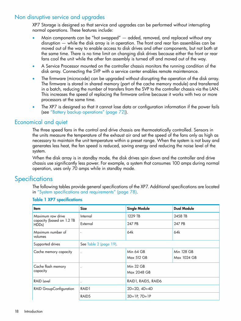
SpecificationsThe following tables provide general specifications of the XP7. Additional specifications are locatedin “System specifications and requirements” (page 78).
Table 1 XP7 specifications
Dual ModuleSingle ModuleSizeItem
2458 TB1229 TBInternalMaximum raw drivecapacity (based on 1.2 TBHDDs) 247 PB247 PBExternal
64k64k-Maximum number ofvolumes
See Table 2 (page 19).Supported drives
Min 128 GBMin 64 GB.Cache memory capacityMax 1024 GBMax 512 GB
Min 32 GB.Cache flash memorycapacity Max 2048 GB
RAID1, RAID5, RAID6.RAID Level
2D+2D, 4D+4DRAID1RAID GroupConfiguration
3D+1P, 7D+1PRAID5
18 Introduction
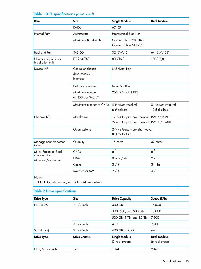
Table 1 XP7 specifications (continued)
Dual ModuleSingle ModuleSizeItem
6D+2PRAID6
Hierarchical Star NetArchitectureInternal Path
Cache Path = 128 GB/sMaximum BandwidthControl Path = 64 GB/s
64 (2WL*32)32 (2WL*6)SAS 6GBack-end Path
160/16,880 /16,8FC 2/4/8GNumber of ports perinstallation unit
SAS/Dual PortController chassisDevice I/Fdrive chassisInterface
Max. 6 GBpsData transfer rate
256 (2.5 inch HDD)Maximum numberof HDD per SAS I/F
8 if drives installed4 if drives installedMaximum number of CHAs12 if diskless6 if diskless
1/2/4 GBps Fibre Channel: 16MFS/16MFLMainframeChannel I/F2/4/8 GBps Fibre Channel: 16MUS/16MUL
2/4/8 GBps Fibre Shortwave:Open systems8UFC/16UFC
32 cores16 coresQuantityManagement ProcessorCores
6 16 1CHAsMicro Processor Bladeconfiguration
2 / 80 or 2 / 42DKAsMinimum/maximum2 / 162 / 8Cache
4 / 82 / 4Switches /CSW
Notes:1. All CHA configuration, no DKAs (diskless system).
Table 2 Drive specifications
Speed (RPM)Drive CapacitySizeDrive Type
15,000300 GB2 1/2 inchHDD (SAS)
10,000300, 600, and 900 GB
7,200500 GB, 1 TB, and 1.2 TB
7,2004 TB3 1/2 inch
n/a400 GB, 800 GB2 1/2 inchSSD (Flash)
Dual ModuleSingle ModuleDrive ChassisDrive Type(6 rack system)(3 rack system)
20481024128HDD, 2 1/2 inch
Specifications 19
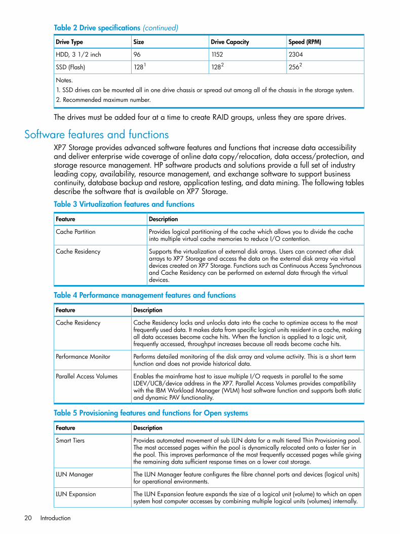
Table 2 Drive specifications (continued)
Speed (RPM)Drive CapacitySizeDrive Type
2304115296HDD, 3 1/2 inch
256212821281SSD (Flash)
Notes.1. SSD drives can be mounted all in one drive chassis or spread out among all of the chassis in the storage system.2. Recommended maximum number.
The drives must be added four at a time to create RAID groups, unless they are spare drives.
Software features and functionsXP7 Storage provides advanced software features and functions that increase data accessibilityand deliver enterprise wide coverage of online data copy/relocation, data access/protection, andstorage resource management. HP software products and solutions provide a full set of industryleading copy, availability, resource management, and exchange software to support businesscontinuity, database backup and restore, application testing, and data mining. The following tablesdescribe the software that is available on XP7 Storage.
Table 3 Virtualization features and functions
DescriptionFeature
Provides logical partitioning of the cache which allows you to divide the cacheinto multiple virtual cache memories to reduce I/O contention.
Cache Partition
Supports the virtualization of external disk arrays. Users can connect other diskarrays to XP7 Storage and access the data on the external disk array via virtual
Cache Residency
devices created on XP7 Storage. Functions such as Continuous Access Synchronousand Cache Residency can be performed on external data through the virtualdevices.
Table 4 Performance management features and functions
DescriptionFeature
Cache Residency locks and unlocks data into the cache to optimize access to the mostfrequently used data. It makes data from specific logical units resident in a cache, making
Cache Residency
all data accesses become cache hits. When the function is applied to a logic unit,frequently accessed, throughput increases because all reads become cache hits.
Performs detailed monitoring of the disk array and volume activity. This is a short termfunction and does not provide historical data.
Performance Monitor
Enables the mainframe host to issue multiple I/O requests in parallel to the sameLDEV/UCB/device address in the XP7. Parallel Access Volumes provides compatibility
Parallel Access Volumes
with the IBM Workload Manager (WLM) host software function and supports both staticand dynamic PAV functionality.
Table 5 Provisioning features and functions for Open systems
DescriptionFeature
Provides automated movement of sub LUN data for a multi tiered Thin Provisioning pool.The most accessed pages within the pool is dynamically relocated onto a faster tier in
Smart Tiers
the pool. This improves performance of the most frequently accessed pages while givingthe remaining data sufficient response times on a lower cost storage.
The LUN Manager feature configures the fibre channel ports and devices (logical units)for operational environments.
LUN Manager
The LUN Expansion feature expands the size of a logical unit (volume) to which an opensystem host computer accesses by combining multiple logical units (volumes) internally.
LUN Expansion
20 Introduction
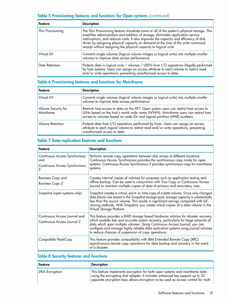
Table 5 Provisioning features and functions for Open systems (continued)
DescriptionFeature
The Thin Provisioning feature virtualizes some or all of the system's physical storage. Thissimplifies administration and addition of storage, eliminates application service
Thin Provisioning
interruptions, and reduces costs. It also improves the capacity and efficiency of diskdrives by assigning physical capacity on demand at the time of the write commandreceipt without assigning the physical capacity to logical units.
Converts single volumes (logical volume images or logical units) into multiple smallervolumes to improve data access performance.
Virtual LVI
Protects data in logical units / volumes / LDEVs from I/O operations illegally performedby host systems. Users can assign an access attribute to each volume to restrict readand/or write operations, preventing unauthorized access to data.
Data Retention
Table 6 Provisioning features and functions for Mainframe
DescriptionFeature
Converts single volumes (logical volume images or logical units) into multiple smallervolumes to improve data access performance.
Virtual LVI
Restricts host access to data on the XP7. Open system users can restrict host access toLUNs based on the host's world wide name (WWN). Mainframe users can restrict hostaccess to volumes based on node IDs and logical partition (LPAR) numbers.
Volume Security forMainframe
Protects data from I/O operations performed by hosts. Users can assign an accessattribute to each logical volume to restrict read and/or write operations, preventingunauthorized access to data.
Volume Retention
Table 7 Data replication features and functions
DescriptionFeature
Performs remote copy operations between disk arrays at different locations.Continuous Access Synchronous provides the synchronous copy mode for open
Continuous Access Synchronousand
systems. Continuous Access Synchronous Z provides synchronous copy for mainframesystems.
Continuous Access SynchronousZ
Creates internal copies of volumes for purposes such as application testing andoffline backup. Can be used in conjunction with True Copy or Continuous AccessJournal to maintain multiple copies of data at primary and secondary sites.
Business Copy andBusiness Copy Z
Snapshot creates a virtual, point- in- time copy of a data volume. Since only changeddata blocks are stored in the Snapshot storage pool, storage capacity is substantially
Snapshot (open systems only)
less than the source volume. This results in significant savings compared with fullcloning methods. With Snapshot, you create virtual copies of a data volume in theVirtual Storage Platform
This feature provides a RAID storage based hardware solution for disaster recoverywhich enables fast and accurate system recovery, particularly for large amounts of
Continuous Access Journal andContinuous Access Journal Z
data which span multiple volumes. Using Continuous Access Journal, you canconfigure and manage highly reliable data replication systems using journal volumesto reduce chances of suspension of copy operations.
This feature provides compatibility with IBM Extended Remote Copy (XRC)asynchronous remote copy operations for data backup and recovery in the eventof a disaster.
Compatible FlashCopy
Table 8 Security features and functions
DescriptionFeature
This feature implements encryption for both open systems and mainframe datausing the encrypting disk adapter. It includes enhanced key support up to 32
DKA Encryption
separate encryption keys allows encryption to be used as access control for multi
Software features and functions 21
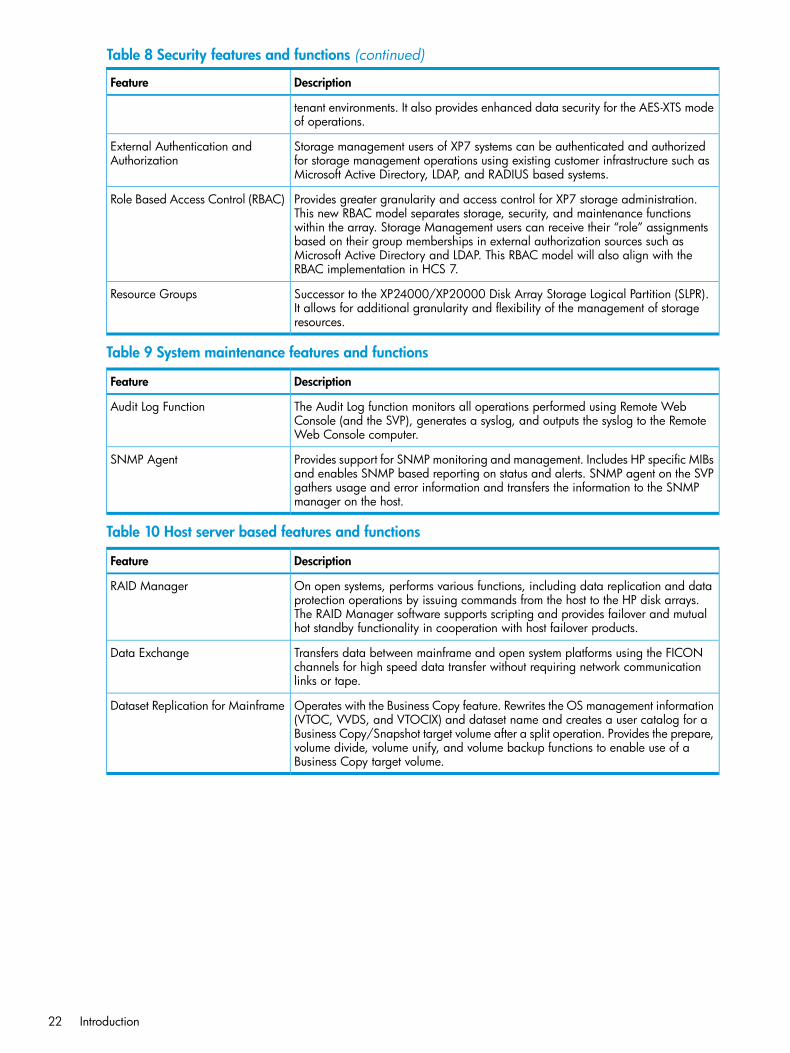
Table 8 Security features and functions (continued)
DescriptionFeature
tenant environments. It also provides enhanced data security for the AES-XTS modeof operations.
Storage management users of XP7 systems can be authenticated and authorizedfor storage management operations using existing customer infrastructure such asMicrosoft Active Directory, LDAP, and RADIUS based systems.
External Authentication andAuthorization
Provides greater granularity and access control for XP7 storage administration.This new RBAC model separates storage, security, and maintenance functions
Role Based Access Control (RBAC)
within the array. Storage Management users can receive their “role” assignmentsbased on their group memberships in external authorization sources such asMicrosoft Active Directory and LDAP. This RBAC model will also align with theRBAC implementation in HCS 7.
Successor to the XP24000/XP20000 Disk Array Storage Logical Partition (SLPR).It allows for additional granularity and flexibility of the management of storageresources.
Resource Groups
Table 9 System maintenance features and functions
DescriptionFeature
The Audit Log function monitors all operations performed using Remote WebConsole (and the SVP), generates a syslog, and outputs the syslog to the RemoteWeb Console computer.
Audit Log Function
Provides support for SNMP monitoring and management. Includes HP specific MIBsand enables SNMP based reporting on status and alerts. SNMP agent on the SVP
SNMP Agent
gathers usage and error information and transfers the information to the SNMPmanager on the host.
Table 10 Host server based features and functions
DescriptionFeature
On open systems, performs various functions, including data replication and dataprotection operations by issuing commands from the host to the HP disk arrays.
RAID Manager
The RAID Manager software supports scripting and provides failover and mutualhot standby functionality in cooperation with host failover products.
Transfers data between mainframe and open system platforms using the FICONchannels for high speed data transfer without requiring network communicationlinks or tape.
Data Exchange
Operates with the Business Copy feature. Rewrites the OS management information(VTOC, VVDS, and VTOCIX) and dataset name and creates a user catalog for a
Dataset Replication for Mainframe
Business Copy/Snapshot target volume after a split operation. Provides the prepare,volume divide, volume unify, and volume backup functions to enable use of aBusiness Copy target volume.
22 Introduction
2 Functional and operational characteristicsSystem architecture overview
This section briefly describes the architecture of XP7 Storage.
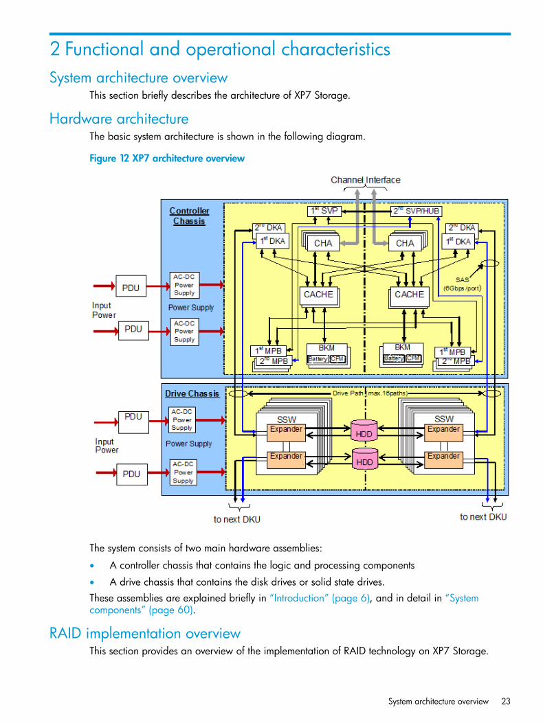
Hardware architectureThe basic system architecture is shown in the following diagram.
Figure 12 XP7 architecture overview
The system consists of two main hardware assemblies:
• A controller chassis that contains the logic and processing components
• A drive chassis that contains the disk drives or solid state drives.These assemblies are explained briefly in “Introduction” (page 6), and in detail in “Systemcomponents” (page 60).
RAID implementation overviewThis section provides an overview of the implementation of RAID technology on XP7 Storage.
System architecture overview 23
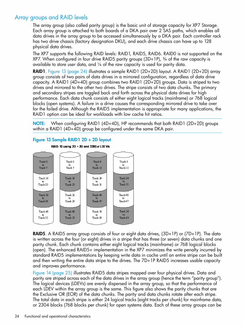
Array groups and RAID levelsThe array group (also called parity group) is the basic unit of storage capacity for XP7 Storage.Each array group is attached to both boards of a DKA pair over 2 SAS paths, which enables alldata drives in the array group to be accessed simultaneously by a DKA pair. Each controller rackhas two drive chassis (factory designation DKU), and each drive chassis can have up to 128physical data drives.The XP7 supports the following RAID levels: RAID1, RAID5, RAID6. RAID0 is not supported on theXP7. When configured in four drive RAID5 parity groups (3D+1P), ¾ of the raw capacity isavailable to store user data, and ¼ of the raw capacity is used for parity data.RAID1. Figure 13 (page 24) illustrates a sample RAID1 (2D+2D) layout. A RAID1 (2D+2D) arraygroup consists of two pairs of data drives in a mirrored configuration, regardless of data drivecapacity. A RAID1 (4D+4D) group combines two RAID1 (2D+2D) groups. Data is striped to twodrives and mirrored to the other two drives. The stripe consists of two data chunks. The primaryand secondary stripes are toggled back and forth across the physical data drives for highperformance. Each data chunk consists of either eight logical tracks (mainframe) or 768 logicalblocks (open systems). A failure in a drive causes the corresponding mirrored drive to take overfor the failed drive. Although the RAID5 implementation is appropriate for many applications, theRAID1 option can be ideal for workloads with low cache hit ratios.
NOTE: When configuring RAID1 (4D+4D), HP recommends that both RAID1 (2D+2D) groupswithin a RAID1 (4D+4D) group be configured under the same DKA pair.
Figure 13 Sample RAID1 2D + 2D layout
RAID5. A RAID5 array group consists of four or eight data drives, (3D+1P) or (7D+1P). The datais written across the four (or eight) drives in a stripe that has three (or seven) data chunks and oneparity chunk. Each chunk contains either eight logical tracks (mainframe) or 768 logical blocks(open). The enhanced RAID5+ implementation in the XP7 minimizes the write penalty incurred bystandard RAID5 implementations by keeping write data in cache until an entire stripe can be builtand then writing the entire data stripe to the drives. The 7D+1P RAID5 increases usable capacityand improves performance.Figure 14 (page 25) illustrates RAID5 data stripes mapped over four physical drives. Data andparity are striped across each of the data drives in the array group (hence the term “parity group”).The logical devices (LDEVs) are evenly dispersed in the array group, so that the performance ofeach LDEV within the array group is the same. This figure also shows the parity chunks that arethe Exclusive OR (EOR) of the data chunks. The parity and data chunks rotate after each stripe.The total data in each stripe is either 24 logical tracks (eight tracks per chunk) for mainframe data,or 2304 blocks (768 blocks per chunk) for open systems data. Each of these array groups can be
24 Functional and operational characteristics
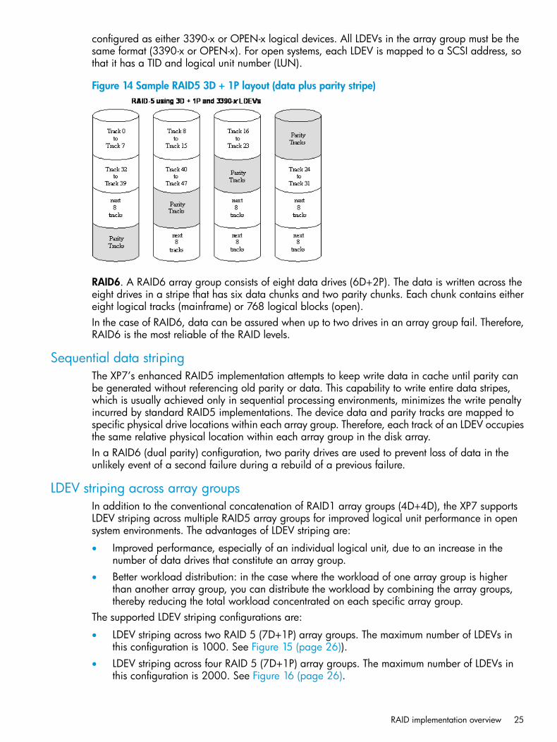
configured as either 3390-x or OPEN-x logical devices. All LDEVs in the array group must be thesame format (3390-x or OPEN-x). For open systems, each LDEV is mapped to a SCSI address, sothat it has a TID and logical unit number (LUN).
Figure 14 Sample RAID5 3D + 1P layout (data plus parity stripe)
RAID6. A RAID6 array group consists of eight data drives (6D+2P). The data is written across theeight drives in a stripe that has six data chunks and two parity chunks. Each chunk contains eithereight logical tracks (mainframe) or 768 logical blocks (open).In the case of RAID6, data can be assured when up to two drives in an array group fail. Therefore,RAID6 is the most reliable of the RAID levels.
Sequential data stripingThe XP7’s enhanced RAID5 implementation attempts to keep write data in cache until parity canbe generated without referencing old parity or data. This capability to write entire data stripes,which is usually achieved only in sequential processing environments, minimizes the write penaltyincurred by standard RAID5 implementations. The device data and parity tracks are mapped tospecific physical drive locations within each array group. Therefore, each track of an LDEV occupiesthe same relative physical location within each array group in the disk array.In a RAID6 (dual parity) configuration, two parity drives are used to prevent loss of data in theunlikely event of a second failure during a rebuild of a previous failure.
LDEV striping across array groupsIn addition to the conventional concatenation of RAID1 array groups (4D+4D), the XP7 supportsLDEV striping across multiple RAID5 array groups for improved logical unit performance in opensystem environments. The advantages of LDEV striping are:
• Improved performance, especially of an individual logical unit, due to an increase in thenumber of data drives that constitute an array group.
• Better workload distribution: in the case where the workload of one array group is higherthan another array group, you can distribute the workload by combining the array groups,thereby reducing the total workload concentrated on each specific array group.
The supported LDEV striping configurations are:
• LDEV striping across two RAID 5 (7D+1P) array groups. The maximum number of LDEVs inthis configuration is 1000. See Figure 15 (page 26)).
• LDEV striping across four RAID 5 (7D+1P) array groups. The maximum number of LDEVs inthis configuration is 2000. See Figure 16 (page 26).
RAID implementation overview 25
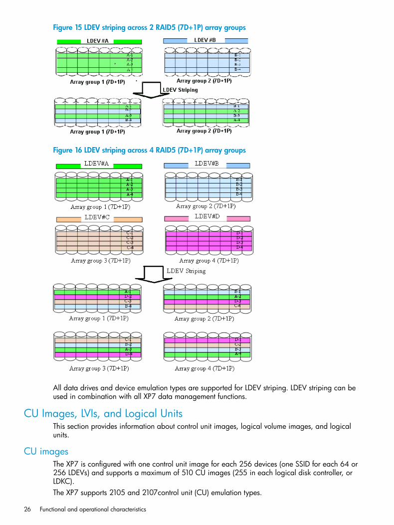
Figure 15 LDEV striping across 2 RAID5 (7D+1P) array groups
Figure 16 LDEV striping across 4 RAID5 (7D+1P) array groups
All data drives and device emulation types are supported for LDEV striping. LDEV striping can beused in combination with all XP7 data management functions.
CU Images, LVIs, and Logical UnitsThis section provides information about control unit images, logical volume images, and logicalunits.
CU imagesThe XP7 is configured with one control unit image for each 256 devices (one SSID for each 64 or256 LDEVs) and supports a maximum of 510 CU images (255 in each logical disk controller, orLDKC).The XP7 supports 2105 and 2107control unit (CU) emulation types.
26 Functional and operational characteristics
The mainframe data management features of the XP7 may have restrictions on CU imagecompatibility.For further information on CU image support, see the Mainframe Host Attachment and OperationsGuide, or contact HP.
Logical Volume imagesThe XP7 supports the following mainframe LVI types:
• 3390-3, -3R, -9, L, and -M. The 3390-3 and 3390-3R LVIs cannot be intermixed in the samedisk array.
• 3380-3, -F, -K.The LVI configuration of XP7 Storage depends on the RAID implementation and physical data drivecapacities. The LDEVs are accessed using a combination of logical disk controller number (00-01),CU number (00-FE), and device number (00-FF). All control unit images can support an installedLVI range of 00 to FF.
Logical UnitsXP7 Storage is configured with OPEN-V logical unit types. The OPEN-V logical unit can vary insize from 48.1 MB to 4 TB. For information on other logical unit types (e.g., OPEN-9), contact HPsupport.For maximum flexibility in logical unit configuration, the XP7 provides the VLL and LUN Expansion(LUSE) features. Using VLL, users can configure multiple logical units under a single LDEV. UsingVirtual LVI or LUSE, users can concatenate multiple logical units into large volumes. For furtherinformation on VLL and Virtual LVI, see the HP XP7 Performance for Open and Mainframe SystemsUser Guide and the HP XP7 Provisioning for Open Systems User Guide
Mainframe operationsThis section provides high level descriptions of mainframe compatibility, support, and configuration.
Mainframe compatibility and functionalityIn addition to full System Managed Storage (SMS) compatibility, XP7 Storage provides the followingfunctions and support in the mainframe environment:
• Sequential data striping
• Cache fast write (CFW) and DASD fast write (DFW)
• Enhanced dynamic cache management
• Extended count key data (ECKD) commands
• Multiple Allegiance
• Concurrent Copy (CC)
• Peer-to-Peer Remote Copy (PPRC)
• Compatible FlashCopy
• Parallel Access Volume (PAV)
• Enhanced CCW
• Priority I/O queuing
• Red Hat Linux for IBM S/390 and zSeries
Mainframe operations 27
Mainframe operating system supportXP7 Storage supports most major IBM Mainframe operating systems and Open System operatingsystems, such as Microsoft Windows, Oracle Solaris, IBM AIX, Linux, HP-UX, and VMware. Formore complete information on the supported operating systems, go to: http://www.hp.com
Mainframe configurationAfter XP7 Storage has been installed, users can configure the disk array for mainframe operations.See the following user documents for information and instructions on configuring XP7 Storage formainframe operations:
• The HP XP7 Mainframe Host Attachment and Operations Guide describes and providesinstructions for configuring the XP7 for mainframe operations, including FICON attachment,hardware definition, cache operations, and device operations.For detailed information on FICON connectivity, FICON/Open intermix configurations, andsupported HBAs, switches, and directors for XP7, please contact HP support.
• The HP XP7 Remote Web Console User Guide provides instructions for installing, configuring,and using Remote Web Console to perform resource and data management operations onXP7 Storage.
• The HP XP7 Provisioning for Mainframe Systems User Guide and HP XP7 Volume Shredderfor Open and Mainframe Systems User Guide provides instructions for converting singlevolumes (LVIs) into multiple smaller volumes to improve data access performance.
System option modes, host modes, and host mode optionsThis section provides detailed information about system option modes. Host modes and host modeoptions are also discussed.
System option modesTo provide greater flexibility and enable XP7 Storage to be tailored to unique customer operatingrequirements, additional operational parameters, or system option modes, are available. Atinstallation, the modes are set to their default values, as shown in the following table. Be sure todiscuss these settings with HP Technical Support. The system option modes can only be changedby HP.The following tables provide information about system option modes and SVP operations:
• Table 11 (page 29) lists the system option mode information for the XP7.
• Table 12 (page 57) specifies the details for mode 269 for Remote Web Console operations.
• Table 13 (page 57) specifies the details of mode 269 for SVP operations.The system option mode information may change in future firmware releases. Contact HP for thelatest information on the XP7 system option modes.The system option mode information includes:
• Mode: Specifies the system option mode number.
• Category: Indicates the functions to which the mode applies.
• Description: Describes the action or function that the mode provides.
• Default: Specifies the default setting (ON or OFF) for the mode.
• MCU/RCU: For remote functions, indicates whether the mode applies to the main control unit(MCU) and/or the remote control unit (RCU).
28 Functional and operational characteristics
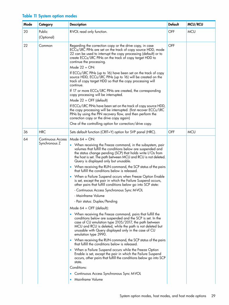
Table 11 System option modes
MCU/RCUDefaultDescriptionCategoryMode
MCUOFFR-VOL read only function.Public20(Optional)
OFFRegarding the correction copy or the drive copy, in caseECCs/LRC PINs are set on the track of copy source HDD, mode
Common22
22 can be used to interrupt the copy processing (default) or tocreate ECCs/LRC PINs on the track of copy target HDD tocontinue the processing.Mode 22 = ON:If ECCs/LRC PINs (up to 16) have been set on the track of copysource HDD, ECCs/LRC PINs (up to 16) will be created on thetrack of copy target HDD so that the copy processing willcontinue.If 17 or more ECCs/LRC PINs are created, the correspondingcopy processing will be interrupted.Mode 22 = OFF (default)If ECCs/LRC PINs have been set on the track of copy source HDD,the copy processing will be interrupted. (first recover ECCs/LRCPINs by using the PIN recovery flow, and then perform thecorrection copy or the drive copy again)One of the controlling option for correction/drive copy.
MCUOFFSets default function (CRIT=Y) option for SVP panel (HRC).HRC36
Mode 64 = ON:Continuous AccessSynchronous Z
64• When receiving the Freeze command, in the subsystem, pair
volumes that fulfill the conditions below are suspended andthe status change pending (SCP) that holds write I/Os fromthe host is set. The path between MCU and RCU is not deleted.Query is displayed only but unusable.
• When receiving the RUN command, the SCP status of the pairsthat fulfill the conditions below is released.
• When a Failure Suspend occurs when Freeze Option Enableis set, except the pair in which the Failure Suspend occurs,other pairs that fulfill conditions below go into SCP state:- Continuous Access Synchronous Sync M-VOL- Mainframe Volume- Pair status: Duplex/Pending
Mode 64 = OFF (default):
• When receiving the Freeze command, pairs that fulfill theconditions below are suspended and the SCP is set. In thecase of CU emulation type 2105/2017, the path betweenMCU and RCU is deleted, while the path is not deleted butunusable with Query displayed only in the case of CUemulation type 3990.
• When receiving the RUN command, the SCP status of the pairsthat fulfill the conditions below is released.
• When a Failure Suspend occurs while the Freeze OptionEnable is set, except the pair in which the Failure Suspendoccurs, other pairs that fulfill the conditions below go into SCPstate.
Conditions:
• Continuous Access Synchronous Sync M-VOL
• Mainframe Volume
System option modes, host modes, and host mode options 29
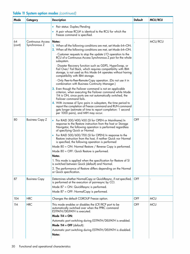
Table 11 System option modes (continued)
MCU/RCUDefaultDescriptionCategoryMode
• Pair status: Duplex/Pending
• A pair whose RCU# is identical to the RCU for which theFreeze command is specified.
MCU/RCU.Notes:Continuous AccessSynchronous Z
64(cont) 1. When all the following conditions are met, set Mode 64=ON.
2. When all the following conditions are met, set Mode 64=ON.- Customer requests to stop the update I/O operation to theRCU of a Continuous Access Synchronous Z pair for the wholesubsystem.- Disaster Recovery function such as GDPS, HyperSwap, orFail Over/ Fail Back, which requires compatibility with IBMstorage, is not used as this Mode 64 operates without havingcompatibility with IBM storage.- Only Peer-to-Peer-Remote-Copy operation. (Do not use it incombination with Business Continuity Manager.)
3. Even though the Failover command is not an applicablecriterion, when executing the Failover command while Mode114 is ON, since ports are not automatically switched, theFailover command fails.
4. With increase of Sync pairs in subsystem, the time period toreport the completion of Freeze command and RUN commandgets longer (estimate of time to report completion: 1 secondper 1000 pairs), and MIH may occur.
-OFFBusiness Copy Z80 • For RAID 300/400/450 (SI for OPEN or Mainframe) Inresponse to the Restore instruction from the host or StorageNavigator, the following operation is performed regardlessof specifying Quick or Normal.
• For RAID 500/600/700 (SI for OPEN) In response to theRestore instruction from the host, if neither Quick nor Normalis specified, the following operation is performed
Mode 80 = ON: Normal Restore / Reverse Copy is performed.Mode 80 = OFF: Quick Restore is performed.Notes.1. This mode is applied when the specification for Restore of SIis switched between Quick (default) and Normal.2. The performance of Restore differs depending on the Normalor Quick specification.
-OFFDetermines whether NormalCopy or QuickResync, if not specified,is performed at the execution of pairresync by CCI.
Business Copy87
Mode 87 = ON: QuickResync is performed.Mode 87 = OFF: NormalCopy is performed.
MCUOFFChanges the default CGROUP Freeze option.HRC104
MCUOFFThis mode enables or disables the LCP/RCP port to beautomatically switched over when the PPRC commandESTPATH/DELPATH is executed.
HRC114
Mode 114 = ON:Automatic port switching during ESTPATH/DELPATH is enabled.Mode 114 = OFF (default):Automatic port switching during ESTPATH/DELPATH is disabled.Notes:
30 Functional and operational characteristics
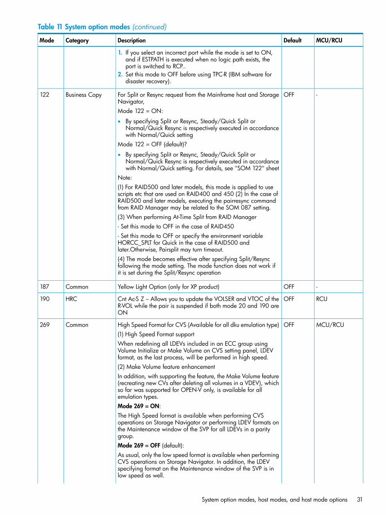
Table 11 System option modes (continued)
MCU/RCUDefaultDescriptionCategoryMode
1. If you select an incorrect port while the mode is set to ON,and if ESTPATH is executed when no logic path exists, theport is switched to RCP..
2. Set this mode to OFF before using TPC-R (IBM software fordisaster recovery).
-OFFFor Split or Resync request from the Mainframe host and StorageNavigator,
Business Copy122
Mode 122 = ON:
• By specifying Split or Resync, Steady/Quick Split orNormal/Quick Resync is respectively executed in accordancewith Normal/Quick setting
Mode 122 = OFF (default)?
• By specifying Split or Resync, Steady/Quick Split orNormal/Quick Resync is respectively executed in accordancewith Normal/Quick setting. For details, see "SOM 122" sheet
Note:(1) For RAID500 and later models, this mode is applied to usescripts etc that are used on RAID400 and 450 (2) In the case ofRAID500 and later models, executing the pairresync commandfrom RAID Manager may be related to the SOM 087 setting.(3) When performing At-Time Split from RAID Manager- Set this mode to OFF in the case of RAID450- Set this mode to OFF or specify the environment variableHORCC_SPLT for Quick in the case of RAID500 andlater.Otherwise, Pairsplit may turn timeout.(4) The mode becomes effective after specifying Split/Resyncfollowing the mode setting. The mode function does not work ifit is set during the Split/Resync operation
-OFFYellow Light Option (only for XP product)Common187
RCUOFFCnt Ac-S Z – Allows you to update the VOLSER and VTOC of theR-VOL while the pair is suspended if both mode 20 and 190 areON
HRC190
MCU/RCUOFFHigh Speed Format for CVS (Available for all dku emulation type)Common269(1) High Speed Format supportWhen redefining all LDEVs included in an ECC group usingVolume Initialize or Make Volume on CVS setting panel, LDEVformat, as the last process, will be performed in high speed.(2) Make Volume feature enhancementIn addition, with supporting the feature, the Make Volume feature(recreating new CVs after deleting all volumes in a VDEV), whichso far was supported for OPEN-V only, is available for allemulation types.Mode 269 = ON:The High Speed format is available when performing CVSoperations on Storage Navigator or performing LDEV formats onthe Maintenance window of the SVP for all LDEVs in a paritygroup.Mode 269 = OFF (default):As usual, only the low speed format is available when performingCVS operations on Storage Navigator. In addition, the LDEVspecifying format on the Maintenance window of the SVP is inlow speed as well.
System option modes, host modes, and host mode options 31
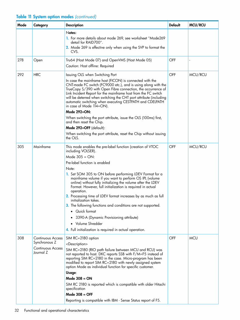
Table 11 System option modes (continued)
MCU/RCUDefaultDescriptionCategoryMode
Notes:1. For more details about mode 269, see worksheet "Mode269
detail for RAID700".2. Mode 269 is effective only when using the SVP to format the
CVS.
-OFFTru64 (Host Mode 07) and OpenVMS (Host Mode 05)Open278Caution: Host offline: Required
MCU/RCUOFFIssuing OLS when Switching PortHRC292In case the mainframe host (FICON) is connected with theCNT-made FC switch (FC9000 etc.), and is using along with theTrueCopy S/390 with Open Fibre connection, the occurrence ofLink Incident Report for the mainframe host from the FC switchwill be deterred when switching the CHT port attribute (includingautomatic switching when executing CESTPATH and CDELPATHin case of Mode 114=ON).Mode 292=ON:When switching the port attribute, issue the OLS (100ms) first,and then reset the Chip.Mode 292=OFF (default):When switching the port attribute, reset the Chip without issuingthe OLS.
MCU/RCUOFFThis mode enables the pre-label function (creation of VTOCincluding VOLSER).
Mainframe305
Mode 305 = ON:Pre-label function is enabledNote:1. Set SOM 305 to ON before performing LDEV Format for a
mainframe volume if you want to perform OS IPL (volumeonline) without fully initializing the volume after the LDEVFormat. However, full initialization is required in actualoperation.
2. Processing time of LDEV format increases by as much as fullinitialization takes.
3. The following functions and conditions are not supported.• Quick format
• 3390-A (Dynamic Provisioning attribute)
• Volume Shredder
4. Full initialization is required in actual operation.
MCUOFFSIM RC=2180 optionContinuous AccessSynchronous Z
308<Description>
Continuous AccessJournal Z
SIM RC=2180 (RIO path failure between MCU and RCU) wasnot reported to host. DKC reports SSB with F/M=F5 instead ofreporting SIM RC=2180 in the case. Micro-program has beenmodified to report SIM RC=2180 with newly assigned systemoption Mode as individual function for specific customer.Usage:Mode 308 = ONSIM RC 2180 is reported which is compatible with older HitachispecificationMode 308 = OFFReporting is compatible with IBM - Sense Status report of F5.
32 Functional and operational characteristics
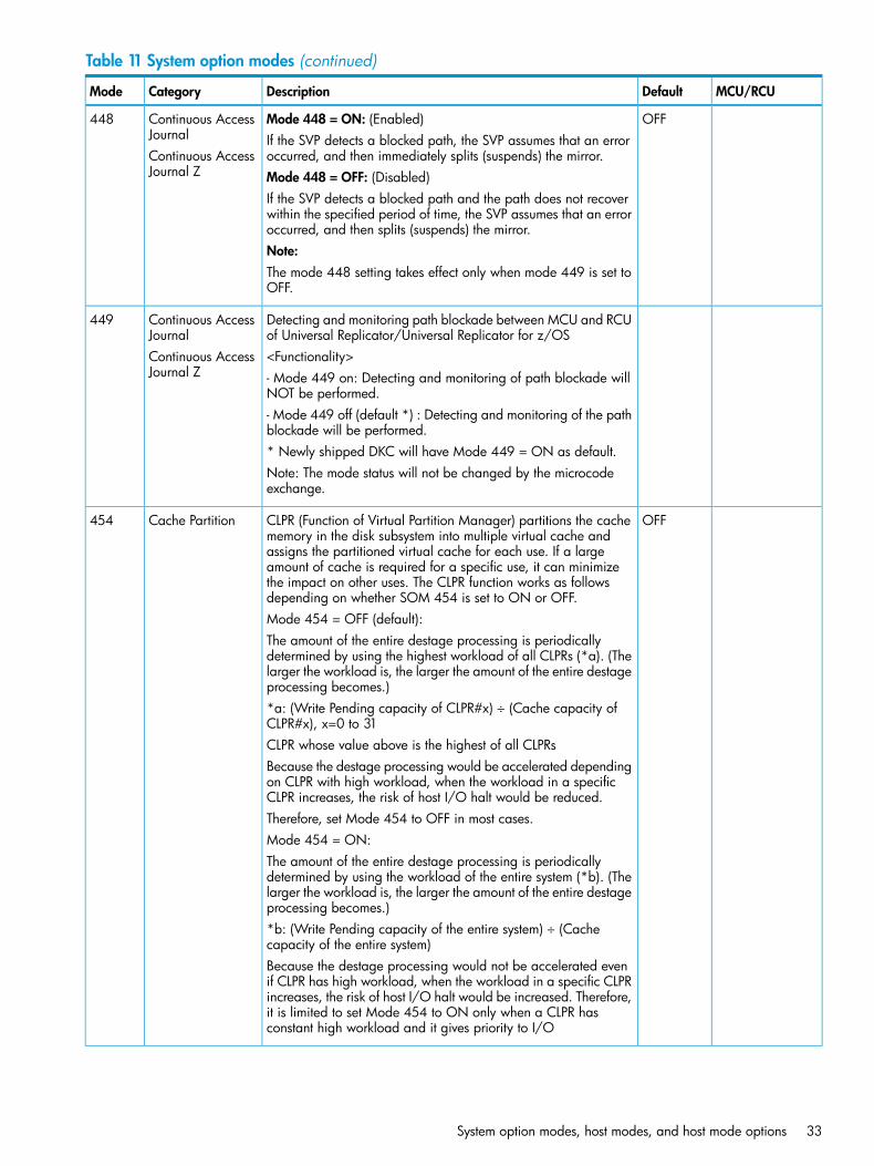
Table 11 System option modes (continued)
MCU/RCUDefaultDescriptionCategoryMode
OFFMode 448 = ON: (Enabled)Continuous AccessJournal
448If the SVP detects a blocked path, the SVP assumes that an erroroccurred, and then immediately splits (suspends) the mirror.Continuous Access
Journal Z Mode 448 = OFF: (Disabled)If the SVP detects a blocked path and the path does not recoverwithin the specified period of time, the SVP assumes that an erroroccurred, and then splits (suspends) the mirror.Note:The mode 448 setting takes effect only when mode 449 is set toOFF.
Detecting and monitoring path blockade between MCU and RCUof Universal Replicator/Universal Replicator for z/OS
Continuous AccessJournal
449
<Functionality>Continuous AccessJournal Z - Mode 449 on: Detecting and monitoring of path blockade will
NOT be performed.- Mode 449 off (default *) : Detecting and monitoring of the pathblockade will be performed.* Newly shipped DKC will have Mode 449 = ON as default.Note: The mode status will not be changed by the microcodeexchange.
OFFCLPR (Function of Virtual Partition Manager) partitions the cachememory in the disk subsystem into multiple virtual cache and
Cache Partition454
assigns the partitioned virtual cache for each use. If a largeamount of cache is required for a specific use, it can minimizethe impact on other uses. The CLPR function works as followsdepending on whether SOM 454 is set to ON or OFF.Mode 454 = OFF (default):The amount of the entire destage processing is periodicallydetermined by using the highest workload of all CLPRs (*a). (Thelarger the workload is, the larger the amount of the entire destageprocessing becomes.)*a: (Write Pending capacity of CLPR#x) ÷ (Cache capacity ofCLPR#x), x=0 to 31CLPR whose value above is the highest of all CLPRsBecause the destage processing would be accelerated dependingon CLPR with high workload, when the workload in a specificCLPR increases, the risk of host I/O halt would be reduced.Therefore, set Mode 454 to OFF in most cases.Mode 454 = ON:The amount of the entire destage processing is periodicallydetermined by using the workload of the entire system (*b). (Thelarger the workload is, the larger the amount of the entire destageprocessing becomes.)*b: (Write Pending capacity of the entire system) ÷ (Cachecapacity of the entire system)Because the destage processing would not be accelerated evenif CLPR has high workload, when the workload in a specific CLPRincreases, the risk of host I/O halt would be increased. Therefore,it is limited to set Mode 454 to ON only when a CLPR hasconstant high workload and it gives priority to I/O
System option modes, host modes, and host mode options 33
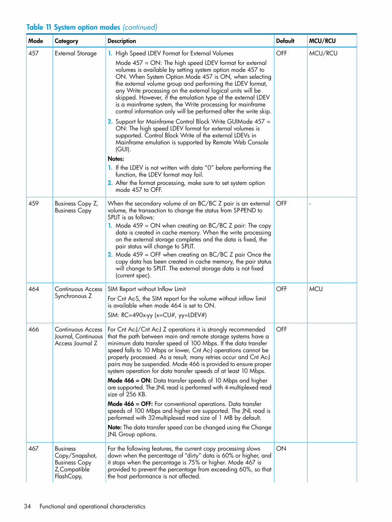
Table 11 System option modes (continued)
MCU/RCUDefaultDescriptionCategoryMode
MCU/RCUOFFExternal Storage457 1. High Speed LDEV Format for External VolumesMode 457 = ON: The high speed LDEV format for externalvolumes is available by setting system option mode 457 toON. When System Option Mode 457 is ON, when selectingthe external volume group and performing the LDEV format,any Write processing on the external logical units will beskipped. However, if the emulation type of the external LDEVis a mainframe system, the Write processing for mainframecontrol information only will be performed after the write skip.
2. Support for Mainframe Control Block Write GUIMode 457 =ON: The high speed LDEV format for external volumes issupported. Control Block Write of the external LDEVs inMainframe emulation is supported by Remote Web Console(GUI).
Notes:1. If the LDEV is not written with data “0” before performing the
function, the LDEV format may fail.2. After the format processing, make sure to set system option
mode 457 to OFF.
-OFFWhen the secondary volume of an BC/BC Z pair is an externalvolume, the transaction to change the status from SP-PEND toSPLIT is as follows:
Business Copy Z,Business Copy
459
1. Mode 459 = ON when creating an BC/BC Z pair: The copydata is created in cache memory. When the write processingon the external storage completes and the data is fixed, thepair status will change to SPLIT.
2. Mode 459 = OFF when creating an BC/BC Z pair Once thecopy data has been created in cache memory, the pair statuswill change to SPLIT. The external storage data is not fixed(current spec).
MCUOFFSIM Report without Inflow LimitContinuous AccessSynchronous Z
464For Cnt Ac-S, the SIM report for the volume without inflow limitis available when mode 464 is set to ON.SIM: RC=490x-yy (x=CU#, yy=LDEV#)
OFFFor Cnt Ac-J/Cnt Ac-J Z operations it is strongly recommendedthat the path between main and remote storage systems have a
Continuous AccessJournal, ContinuousAccess Journal Z
466
minimum data transfer speed of 100 Mbps. If the data transferspeed falls to 10 Mbps or lower, Cnt Ac-J operations cannot beproperly processed. As a result, many retries occur and Cnt Ac-Jpairs may be suspended. Mode 466 is provided to ensure propersystem operation for data transfer speeds of at least 10 Mbps.Mode 466 = ON: Data transfer speeds of 10 Mbps and higherare supported. The JNL read is performed with 4-multiplexed readsize of 256 KB.Mode 466 = OFF: For conventional operations. Data transferspeeds of 100 Mbps and higher are supported. The JNL read isperformed with 32-multiplexed read size of 1 MB by default.Note: The data transfer speed can be changed using the ChangeJNL Group options.
ONFor the following features, the current copy processing slowsdown when the percentage of “dirty” data is 60% or higher, and
BusinessCopy/Snapshot,
467
it stops when the percentage is 75% or higher. Mode 467 isBusiness Copyprovided to prevent the percentage from exceeding 60%, so thatthe host performance is not affected.
Z,CompatibleFlashCopy,
34 Functional and operational characteristics
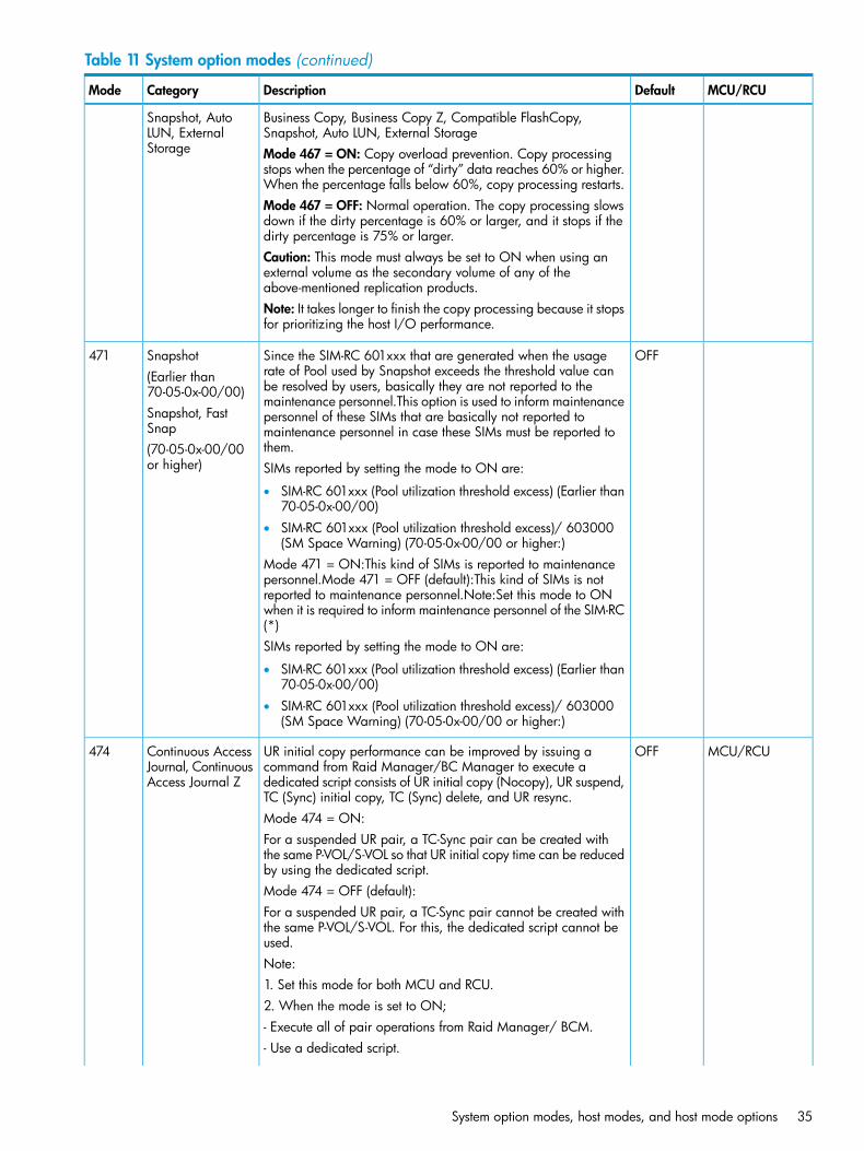
Table 11 System option modes (continued)
MCU/RCUDefaultDescriptionCategoryMode
Business Copy, Business Copy Z, Compatible FlashCopy,Snapshot, Auto LUN, External Storage
Snapshot, AutoLUN, ExternalStorage Mode 467 = ON: Copy overload prevention. Copy processing
stops when the percentage of “dirty” data reaches 60% or higher.When the percentage falls below 60%, copy processing restarts.Mode 467 = OFF: Normal operation. The copy processing slowsdown if the dirty percentage is 60% or larger, and it stops if thedirty percentage is 75% or larger.Caution: This mode must always be set to ON when using anexternal volume as the secondary volume of any of theabove-mentioned replication products.Note: It takes longer to finish the copy processing because it stopsfor prioritizing the host I/O performance.
OFFSince the SIM-RC 601xxx that are generated when the usagerate of Pool used by Snapshot exceeds the threshold value can
Snapshot(Earlier than70-05-0x-00/00)
471
be resolved by users, basically they are not reported to themaintenance personnel.This option is used to inform maintenance
Snapshot, FastSnap
personnel of these SIMs that are basically not reported tomaintenance personnel in case these SIMs must be reported tothem.(70-05-0x-00/00
or higher) SIMs reported by setting the mode to ON are:
• SIM-RC 601xxx (Pool utilization threshold excess) (Earlier than70-05-0x-00/00)
• SIM-RC 601xxx (Pool utilization threshold excess)/ 603000(SM Space Warning) (70-05-0x-00/00 or higher:)
Mode 471 = ON:This kind of SIMs is reported to maintenancepersonnel.Mode 471 = OFF (default):This kind of SIMs is notreported to maintenance personnel.Note:Set this mode to ONwhen it is required to inform maintenance personnel of the SIM-RC(*)SIMs reported by setting the mode to ON are:
• SIM-RC 601xxx (Pool utilization threshold excess) (Earlier than70-05-0x-00/00)
• SIM-RC 601xxx (Pool utilization threshold excess)/ 603000(SM Space Warning) (70-05-0x-00/00 or higher:)
MCU/RCUOFFUR initial copy performance can be improved by issuing acommand from Raid Manager/BC Manager to execute a
Continuous AccessJournal, ContinuousAccess Journal Z
474
dedicated script consists of UR initial copy (Nocopy), UR suspend,TC (Sync) initial copy, TC (Sync) delete, and UR resync.Mode 474 = ON:For a suspended UR pair, a TC-Sync pair can be created withthe same P-VOL/S-VOL so that UR initial copy time can be reducedby using the dedicated script.Mode 474 = OFF (default):For a suspended UR pair, a TC-Sync pair cannot be created withthe same P-VOL/S-VOL. For this, the dedicated script cannot beused.Note:1. Set this mode for both MCU and RCU.2. When the mode is set to ON;- Execute all of pair operations from Raid Manager/ BCM.- Use a dedicated script.
System option modes, host modes, and host mode options 35
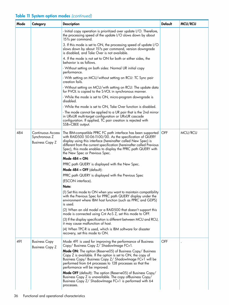
Table 11 System option modes (continued)
MCU/RCUDefaultDescriptionCategoryMode
- Initial copy operation is prioritized over update I/O. Therefore,the processing speed of the update I/O slows down by about15?s per command.3. If this mode is set to ON, the processing speed of update I/Oslows down by about 15?s per command, version downgradeis disabled, and Take Over is not available.4. If the mode is not set to ON for both or either sides, thebehavior is as follows.- Without setting on both sides: Normal UR initial copyperformance.- With setting on MCU/without setting on RCU: TC Sync paircreation fails.- Without setting on MCU/with setting on RCU: The update datafor P-VOL is copied to the S-VOL in synchronous manner.- While the mode is set to ON, micro-program downgrade isdisabled.- While the mode is set to ON, Take Over function is disabled.- The mode cannot be applied to a UR pair that is the 2nd mirrorin URxUR multi-target configuration or URxUR cascadeconfiguration. If applied, TC pair creation is rejected withSSB=CBEE output.
MCU/RCUOFFThe IBM-compatible PPRC FC path interface has been supportedwith RAID500 50-06-11-00/00. As the specification of QUERY
Continuous AccessSynchronous Z
484
display using this interface (hereinafter called New Spec) isBusiness Copy Zdifferent from the current specification (hereinafter called PreviousSpec), this mode enables to display the PPRC path QUERY withthe New Spec or Previous Spec.Mode 484 = ON:PPRC path QUERY is displayed with the New Spec.Mode 484 = OFF (default):PPRC path QUERY is displayed with the Previous Spec(ESCON interface).Note:(1) Set this mode to ON when you want to maintain compatibilitywith the Previous Spec for PPRC path QUERY display under theenvironment where IBM host function (such as PPRC and GDPS)is used.(2) When an old model or a RAID500 that doesn’t support thismode is connected using Cnt Ac-S Z, set this mode to OFF.(3) If the display specification is different between MCU and RCU,it may cause malfunction of host.(4) When TPC-R is used, which is IBM software for disasterrecovery, set this mode to ON.
.OFFMode 491 is used for improving the performance of BusinessCopy/ Business Copy Z/ ShadowImage FCv1.
Business CopyBusiness Copy Z
491
Mode ON: The option (Reserve05) of Business Copy/ BusinessCopy Z is available. If the option is set to ON, the copy ofBusiness Copy/ Business Copy Z/ ShadowImage FCv1 will beperformed from 64 processes to 128 processes so that theperformance will be improved.Mode OFF (default): The option (Reserve05) of Business Copy/Business Copy Z is unavailable. The copy ofBusiness Copy/Business Copy Z/ ShadowImage FCv1 is performed with 64processes.
36 Functional and operational characteristics
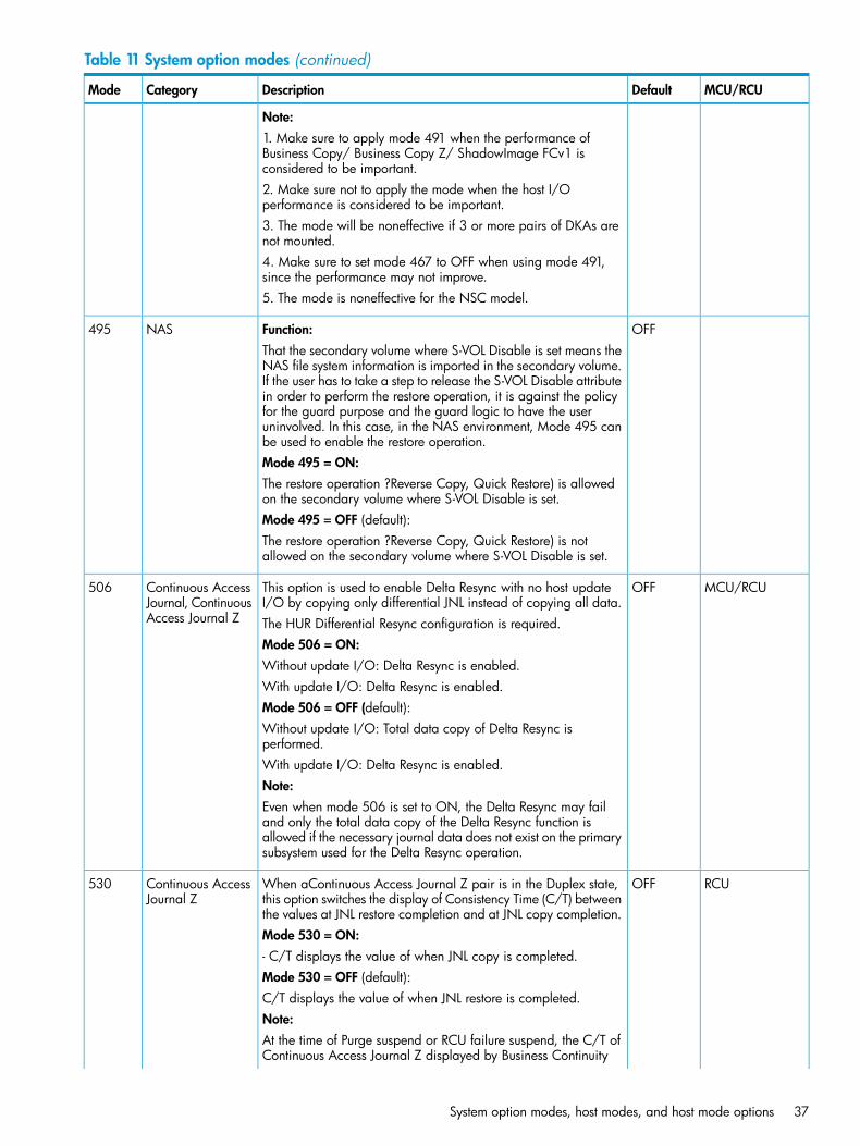
Table 11 System option modes (continued)
MCU/RCUDefaultDescriptionCategoryMode
Note:1. Make sure to apply mode 491 when the performance ofBusiness Copy/ Business Copy Z/ ShadowImage FCv1 isconsidered to be important.2. Make sure not to apply the mode when the host I/Operformance is considered to be important.3. The mode will be noneffective if 3 or more pairs of DKAs arenot mounted.4. Make sure to set mode 467 to OFF when using mode 491,since the performance may not improve.5. The mode is noneffective for the NSC model.
OFFFunction:NAS495That the secondary volume where S-VOL Disable is set means theNAS file system information is imported in the secondary volume.If the user has to take a step to release the S-VOL Disable attributein order to perform the restore operation, it is against the policyfor the guard purpose and the guard logic to have the useruninvolved. In this case, in the NAS environment, Mode 495 canbe used to enable the restore operation.Mode 495 = ON:The restore operation ?Reverse Copy, Quick Restore) is allowedon the secondary volume where S-VOL Disable is set.Mode 495 = OFF (default):The restore operation ?Reverse Copy, Quick Restore) is notallowed on the secondary volume where S-VOL Disable is set.
MCU/RCUOFFThis option is used to enable Delta Resync with no host updateI/O by copying only differential JNL instead of copying all data.
Continuous AccessJournal, ContinuousAccess Journal Z
506
The HUR Differential Resync configuration is required.Mode 506 = ON:Without update I/O: Delta Resync is enabled.With update I/O: Delta Resync is enabled.Mode 506 = OFF (default):Without update I/O: Total data copy of Delta Resync isperformed.With update I/O: Delta Resync is enabled.Note:Even when mode 506 is set to ON, the Delta Resync may failand only the total data copy of the Delta Resync function isallowed if the necessary journal data does not exist on the primarysubsystem used for the Delta Resync operation.
RCUOFFWhen aContinuous Access Journal Z pair is in the Duplex state,this option switches the display of Consistency Time (C/T) betweenthe values at JNL restore completion and at JNL copy completion.
Continuous AccessJournal Z
530
Mode 530 = ON:- C/T displays the value of when JNL copy is completed.Mode 530 = OFF (default):C/T displays the value of when JNL restore is completed.Note:At the time of Purge suspend or RCU failure suspend, the C/T ofContinuous Access Journal Z displayed by Business Continuity
System option modes, host modes, and host mode options 37
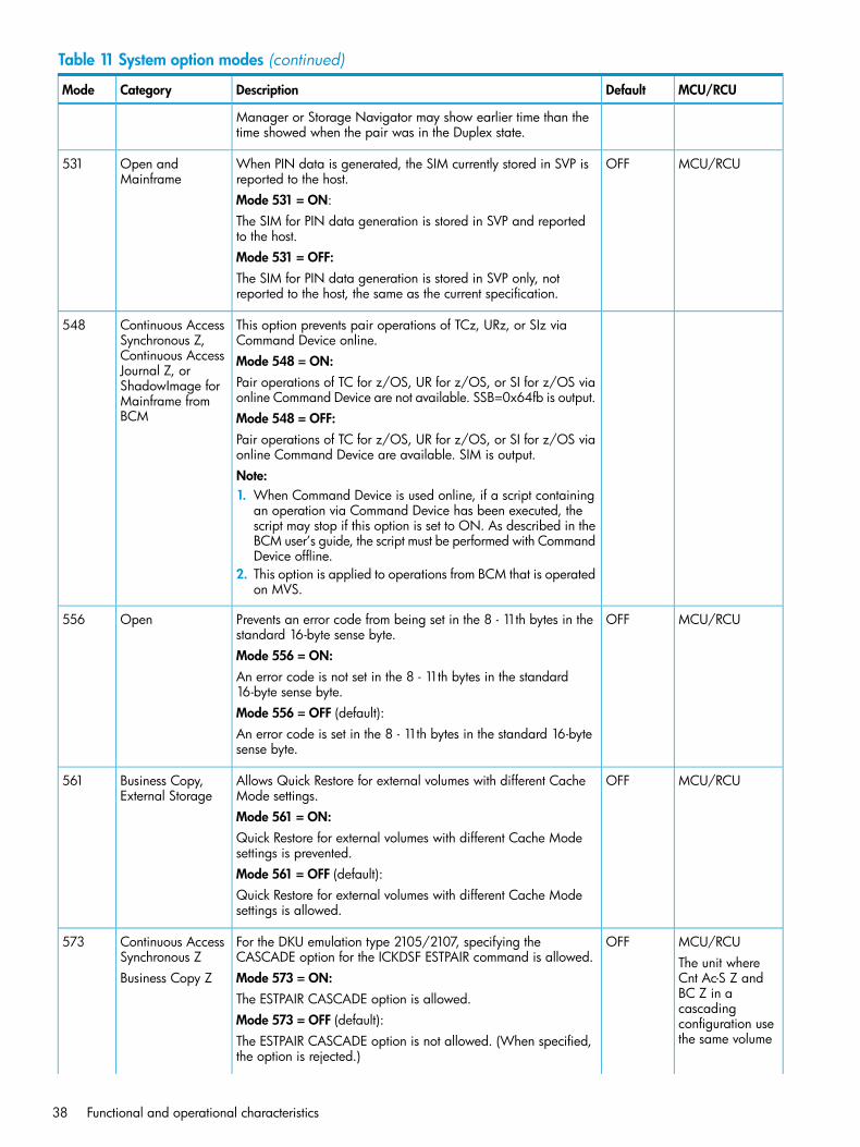
Table 11 System option modes (continued)
MCU/RCUDefaultDescriptionCategoryMode
Manager or Storage Navigator may show earlier time than thetime showed when the pair was in the Duplex state.
MCU/RCUOFFWhen PIN data is generated, the SIM currently stored in SVP isreported to the host.
Open andMainframe
531
Mode 531 = ON:The SIM for PIN data generation is stored in SVP and reportedto the host.Mode 531 = OFF:The SIM for PIN data generation is stored in SVP only, notreported to the host, the same as the current specification.
This option prevents pair operations of TCz, URz, or SIz viaCommand Device online.
Continuous AccessSynchronous Z,
548
Mode 548 = ON:Continuous AccessJournal Z, or
Pair operations of TC for z/OS, UR for z/OS, or SI for z/OS viaonline Command Device are not available. SSB=0x64fb is output.
ShadowImage forMainframe fromBCM Mode 548 = OFF:
Pair operations of TC for z/OS, UR for z/OS, or SI for z/OS viaonline Command Device are available. SIM is output.Note:1. When Command Device is used online, if a script containing
an operation via Command Device has been executed, thescript may stop if this option is set to ON. As described in theBCM user’s guide, the script must be performed with CommandDevice offline.
2. This option is applied to operations from BCM that is operatedon MVS.
MCU/RCUOFFPrevents an error code from being set in the 8 - 11th bytes in thestandard 16-byte sense byte.
Open556
Mode 556 = ON:An error code is not set in the 8 - 11th bytes in the standard16-byte sense byte.Mode 556 = OFF (default):An error code is set in the 8 - 11th bytes in the standard 16-bytesense byte.
MCU/RCUOFFAllows Quick Restore for external volumes with different CacheMode settings.
Business Copy,External Storage
561
Mode 561 = ON:Quick Restore for external volumes with different Cache Modesettings is prevented.Mode 561 = OFF (default):Quick Restore for external volumes with different Cache Modesettings is allowed.
MCU/RCUOFFFor the DKU emulation type 2105/2107, specifying theCASCADE option for the ICKDSF ESTPAIR command is allowed.
Continuous AccessSynchronous Z
573The unit whereCnt Ac-S Z andMode 573 = ON:Business Copy ZBC Z in aThe ESTPAIR CASCADE option is allowed.cascading
Mode 573 = OFF (default): configuration usethe same volumeThe ESTPAIR CASCADE option is not allowed. (When specified,
the option is rejected.)
38 Functional and operational characteristics
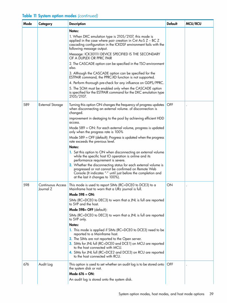
Table 11 System option modes (continued)
MCU/RCUDefaultDescriptionCategoryMode
Notes:1. When DKC emulation type is 2105/2107, this mode isapplied in the case where pair creation in Cnt Ac-S Z – BC Zcascading configuration in the ICKDSF environment fails with thefollowing message output.Message: ICK30111I DEVICE SPECIFIED IS THE SECONDARYOF A DUPLEX OR PPRC PAIR2. The CASCADE option can be specified in the TSO environmentalso.3. Although the CASCADE option can be specified for theESTPAIR command, the PPRC-XD function is not supported.4. Perform thorough pre-check for any influence on GDPS/PPRC.5. The SOM must be enabled only when the CASCADE optionis specified for the ESTPAIR command for the DKC emulation type2105/2107.
.OFFTurning this option ON changes the frequency of progress updateswhen disconnecting an external volume. of disconnection ischanged.
External Storage589
improvement in destaging to the pool by achieving efficient HDDaccess.Mode 589 = ON: For each external volume, progress is updatedonly when the progress rate is 100%Mode 589 = OFF (default): Progress is updated when the progressrate exceeds the previous level.Notes:1. Set this option to ON when disconnecting an external volume
while the specific host IO operation is online and itsperformance requirement is severe.
2. Whether the disconnecting status for each external volume isprogressed or not cannot be confirmed on Remote WebConsole (It indicates “-“ until just before the completion andat the last it changes to 100%).
.ONThis mode is used to report SIMs (RC=DCE0 to DCE3) to aMainframe host to warn that a URz journal is full.
Continuous AccessJournal Z
598
Mode 598 = ON:SIMs (RC=DCE0 to DEC3) to warn that a JNL is full are reportedto SVP and the host.Mode 598= OFF (default):SIMs (RC=DCE0 to DEC3) to warn that a JNL is full are reportedto SVP only.Notes:1. This mode is applied if SIMs (RC=DCE0 to DCE3) need to be
reported to a Mainframe host.2. The SIMs are not reported to the Open server.3. SIMs for JNL full (RC=DCE0 and DCE1) on MCU are reported
to the host connected with MCU.4. SIMs for JNL full (RC=DCE2 and DCE3) on RCU are reported
to the host connected with RCU.
.OFFThis option is used to set whether an audit log is to be stored ontothe system disk or not.
Audit Log676
Mode 676 = ON:An audit log is stored onto the system disk.
System option modes, host modes, and host mode options 39
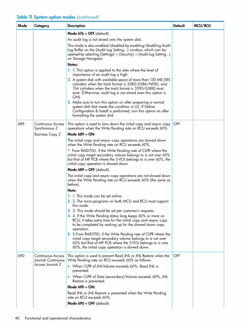
Table 11 System option modes (continued)
MCU/RCUDefaultDescriptionCategoryMode
Mode 676 = OFF (default):An audit log is not stored onto the system disk.This mode is also enabled/disabled by enabling/disabling AuditLog Buffer on the [Audit Log Setting...] window, which can beopened by selecting [Settings] -> [Security] -> [Audit Log Setting...]on Storage Navigator.Notes:1. 1. This option is applied to the sites where the level of
importance of an audit log is high.2. A system disk with available space of more than 130 MB (185
cylinders when the track format is 3380/6586/NF80, and154 cylinders when the track format is 3390/6588) mustexist. (Otherwise, audit log is not stored even this option isON).
3. Make sure to turn this option on after preparing a normalsystem disk that meets the condition in (2). If DefineConfiguration & Install is performed, turn this option on afterformatting the system disk.
.OFFThis option is used to slow down the initial copy and resync copyoperations when the Write Pending rate on RCU exceeds 60%.
Continuous AccessSynchronous Z
689
Mode 689 = ON:Business Copy ZThe initial copy and resync copy operations are slowed downwhen the Write Pending rate on RCU exceeds 60%.*: From RAID700, if the Write Pending rate of CLPR where theinitial copy target secondary volume belongs to is not over 60%but that of MP PCB where the S-VOL belongs to is over 60%, theinitial copy operation is slowed down.Mode 689 = OFF (default):The initial copy and resync copy operations are not slowed downwhen the Write Pending rate on RCU exceeds 60% (the same asbefore).Note:1. 1. This mode can be set online.2. 2. The micro-programs on both MCU and RCU must support
this mode.3. 3. This mode should be set per customer’s requests.4. 4. If the Write Pending status long keeps 60% or more on
RCU, it takes extra time for the initial copy and resync copyto be completed by making up for the slowed down copyoperation.
5. 5.From RAID700, if the Write Pending rate of CLPR where theinitial copy target secondary volume belongs to is not over60% but that of MP PCB where the S-VOL belongs to is over60%, the initial copy operation is slowed down.
.OFFThis option is used to prevent Read JNL or JNL Restore when theWrite Pending rate on RCU exceeds 60% as follows:
Continuous AccessJournal, ContinuousAccess Journal Z
690
• When CLPR of JNL-Volume exceeds 60%, Read JNL isprevented.
• When CLPR of Data (secondary)-Volume exceeds 60%, JNLRestore is prevented.
Mode 690 = ON:Read JNL or JNL Restore is prevented when the Write Pendingrate on RCU exceeds 60%.Mode 690 = OFF (default):
40 Functional and operational characteristics
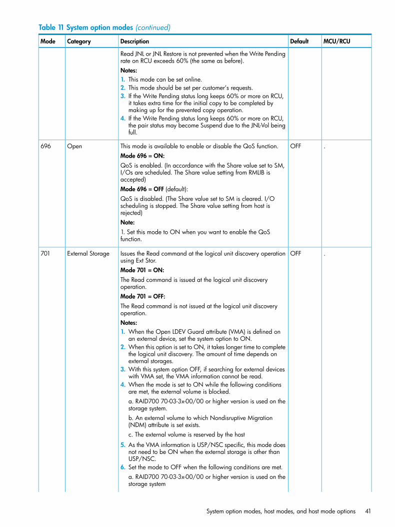
Table 11 System option modes (continued)
MCU/RCUDefaultDescriptionCategoryMode
Read JNL or JNL Restore is not prevented when the Write Pendingrate on RCU exceeds 60% (the same as before).Notes:1. This mode can be set online.2. This mode should be set per customer’s requests.3. If the Write Pending status long keeps 60% or more on RCU,
it takes extra time for the initial copy to be completed bymaking up for the prevented copy operation.
4. If the Write Pending status long keeps 60% or more on RCU,the pair status may become Suspend due to the JNL-Vol beingfull.
.OFFThis mode is available to enable or disable the QoS function.Open696Mode 696 = ON:QoS is enabled. (In accordance with the Share value set to SM,I/Os are scheduled. The Share value setting from RMLIB isaccepted)Mode 696 = OFF (default):QoS is disabled. (The Share value set to SM is cleared. I/Oscheduling is stopped. The Share value setting from host isrejected)Note:1. Set this mode to ON when you want to enable the QoSfunction.
.OFFIssues the Read command at the logical unit discovery operationusing Ext Stor.
External Storage701
Mode 701 = ON:The Read command is issued at the logical unit discoveryoperation.Mode 701 = OFF:The Read command is not issued at the logical unit discoveryoperation.Notes:1. When the Open LDEV Guard attribute (VMA) is defined on
an external device, set the system option to ON.2. When this option is set to ON, it takes longer time to complete
the logical unit discovery. The amount of time depends onexternal storages.
3. With this system option OFF, if searching for external deviceswith VMA set, the VMA information cannot be read.
4. When the mode is set to ON while the following conditionsare met, the external volume is blocked.a. RAID700 70-03-3x-00/00 or higher version is used on thestorage system.b. An external volume to which Nondisruptive Migration(NDM) attribute is set exists.c. The external volume is reserved by the host
5. As the VMA information is USP/NSC specific, this mode doesnot need to be ON when the external storage is other thanUSP/NSC.
6. Set the mode to OFF when the following conditions are met.a. RAID700 70-03-3x-00/00 or higher version is used on thestorage system
System option modes, host modes, and host mode options 41
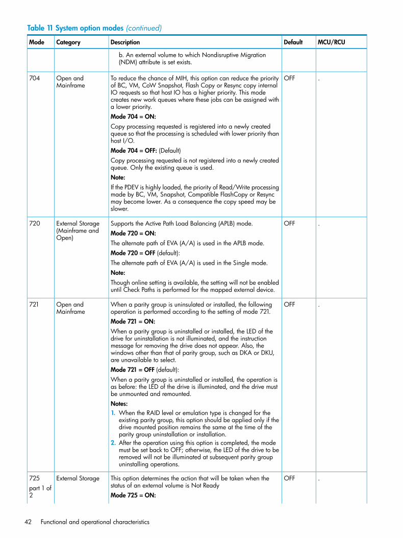
Table 11 System option modes (continued)
MCU/RCUDefaultDescriptionCategoryMode
b. An external volume to which Nondisruptive Migration(NDM) attribute is set exists.
.OFFTo reduce the chance of MIH, this option can reduce the priorityof BC, VM, CoW Snapshot, Flash Copy or Resync copy internal
Open andMainframe
704
IO requests so that host IO has a higher priority. This modecreates new work queues where these jobs can be assigned witha lower priority.Mode 704 = ON:Copy processing requested is registered into a newly createdqueue so that the processing is scheduled with lower priority thanhost I/O.Mode 704 = OFF: (Default)Copy processing requested is not registered into a newly createdqueue. Only the existing queue is used.Note:If the PDEV is highly loaded, the priority of Read/Write processingmade by BC, VM, Snapshot, Compatible FlashCopy or Resyncmay become lower. As a consequence the copy speed may beslower.
.OFFSupports the Active Path Load Balancing (APLB) mode.External Storage(Mainframe andOpen)
720Mode 720 = ON:The alternate path of EVA (A/A) is used in the APLB mode.Mode 720 = OFF (default):The alternate path of EVA (A/A) is used in the Single mode.Note:Though online setting is available, the setting will not be enableduntil Check Paths is performed for the mapped external device.
.OFFWhen a parity group is uninsulated or installed, the followingoperation is performed according to the setting of mode 721.
Open andMainframe
721
Mode 721 = ON:When a parity group is uninstalled or installed, the LED of thedrive for uninstallation is not illuminated, and the instructionmessage for removing the drive does not appear. Also, thewindows other than that of parity group, such as DKA or DKU,are unavailable to select.Mode 721 = OFF (default):When a parity group is uninstalled or installed, the operation isas before: the LED of the drive is illuminated, and the drive mustbe unmounted and remounted.Notes:1. When the RAID level or emulation type is changed for the
existing parity group, this option should be applied only if thedrive mounted position remains the same at the time of theparity group uninstallation or installation.
2. After the operation using this option is completed, the modemust be set back to OFF; otherwise, the LED of the drive to beremoved will not be illuminated at subsequent parity groupuninstalling operations.
.OFFThis option determines the action that will be taken when thestatus of an external volume is Not Ready
External Storage725part 1 of2 Mode 725 = ON:
42 Functional and operational characteristics
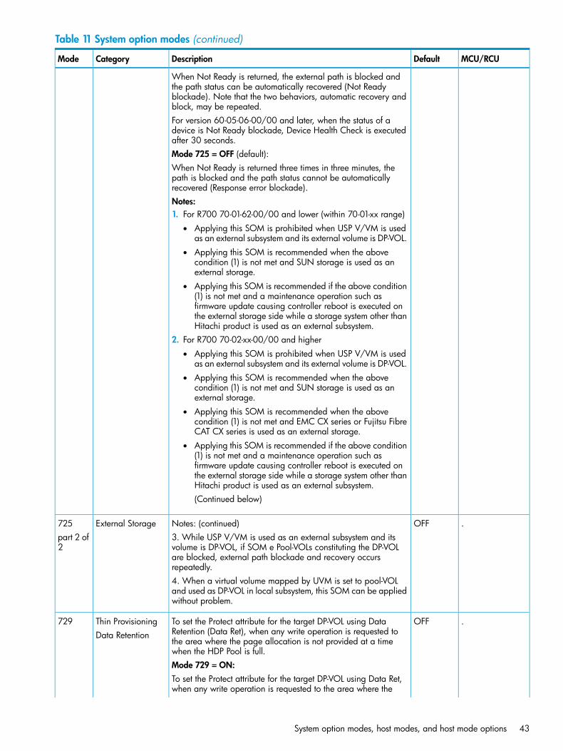
Table 11 System option modes (continued)
MCU/RCUDefaultDescriptionCategoryMode
When Not Ready is returned, the external path is blocked andthe path status can be automatically recovered (Not Readyblockade). Note that the two behaviors, automatic recovery andblock, may be repeated.For version 60-05-06-00/00 and later, when the status of adevice is Not Ready blockade, Device Health Check is executedafter 30 seconds.Mode 725 = OFF (default):When Not Ready is returned three times in three minutes, thepath is blocked and the path status cannot be automaticallyrecovered (Response error blockade).Notes:1. For R700 70-01-62-00/00 and lower (within 70-01-xx range)
• Applying this SOM is prohibited when USP V/VM is usedas an external subsystem and its external volume is DP-VOL.
• Applying this SOM is recommended when the abovecondition (1) is not met and SUN storage is used as anexternal storage.
• Applying this SOM is recommended if the above condition(1) is not met and a maintenance operation such asfirmware update causing controller reboot is executed onthe external storage side while a storage system other thanHitachi product is used as an external subsystem.
2. For R700 70-02-xx-00/00 and higher• Applying this SOM is prohibited when USP V/VM is used
as an external subsystem and its external volume is DP-VOL.• Applying this SOM is recommended when the above
condition (1) is not met and SUN storage is used as anexternal storage.
• Applying this SOM is recommended when the abovecondition (1) is not met and EMC CX series or Fujitsu FibreCAT CX series is used as an external storage.
• Applying this SOM is recommended if the above condition(1) is not met and a maintenance operation such asfirmware update causing controller reboot is executed onthe external storage side while a storage system other thanHitachi product is used as an external subsystem.(Continued below)
.OFFNotes: (continued)External Storage7253. While USP V/VM is used as an external subsystem and itsvolume is DP-VOL, if SOM e Pool-VOLs constituting the DP-VOL
part 2 of2
are blocked, external path blockade and recovery occursrepeatedly.4. When a virtual volume mapped by UVM is set to pool-VOLand used as DP-VOL in local subsystem, this SOM can be appliedwithout problem.
.OFFTo set the Protect attribute for the target DP-VOL using DataRetention (Data Ret), when any write operation is requested to
Thin ProvisioningData Retention
729
the area where the page allocation is not provided at a timewhen the HDP Pool is full.Mode 729 = ON:To set the Protect attribute for the target DP-VOL using Data Ret,when any write operation is requested to the area where the
System option modes, host modes, and host mode options 43
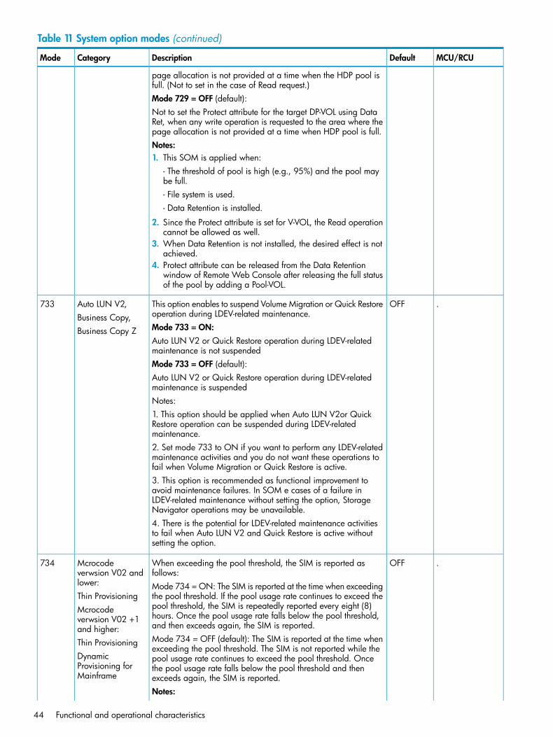
Table 11 System option modes (continued)
MCU/RCUDefaultDescriptionCategoryMode
page allocation is not provided at a time when the HDP pool isfull. (Not to set in the case of Read request.)Mode 729 = OFF (default):Not to set the Protect attribute for the target DP-VOL using DataRet, when any write operation is requested to the area where thepage allocation is not provided at a time when HDP pool is full.Notes:1. This SOM is applied when:
- The threshold of pool is high (e.g., 95%) and the pool maybe full.- File system is used.- Data Retention is installed.
2. Since the Protect attribute is set for V-VOL, the Read operationcannot be allowed as well.
3. When Data Retention is not installed, the desired effect is notachieved.
4. Protect attribute can be released from the Data Retentionwindow of Remote Web Console after releasing the full statusof the pool by adding a Pool-VOL.
.OFFThis option enables to suspend Volume Migration or Quick Restoreoperation during LDEV-related maintenance.
Auto LUN V2,Business Copy,
733
Mode 733 = ON:Business Copy ZAuto LUN V2 or Quick Restore operation during LDEV-relatedmaintenance is not suspendedMode 733 = OFF (default):Auto LUN V2 or Quick Restore operation during LDEV-relatedmaintenance is suspendedNotes:1. This option should be applied when Auto LUN V2or QuickRestore operation can be suspended during LDEV-relatedmaintenance.2. Set mode 733 to ON if you want to perform any LDEV-relatedmaintenance activities and you do not want these operations tofail when Volume Migration or Quick Restore is active.3. This option is recommended as functional improvement toavoid maintenance failures. In SOM e cases of a failure inLDEV-related maintenance without setting the option, StorageNavigator operations may be unavailable.4. There is the potential for LDEV-related maintenance activitiesto fail when Auto LUN V2 and Quick Restore is active withoutsetting the option.
.OFFWhen exceeding the pool threshold, the SIM is reported asfollows:
Mcrocodeverwsion V02 andlower:
734
Mode 734 = ON: The SIM is reported at the time when exceedingthe pool threshold. If the pool usage rate continues to exceed theThin Provisioningpool threshold, the SIM is repeatedly reported every eight (8)Mcrocode
verwsion V02 +1and higher:
hours. Once the pool usage rate falls below the pool threshold,and then exceeds again, the SIM is reported.Mode 734 = OFF (default): The SIM is reported at the time whenexceeding the pool threshold. The SIM is not reported while the
Thin ProvisioningDynamicProvisioning forMainframe
pool usage rate continues to exceed the pool threshold. Oncethe pool usage rate falls below the pool threshold and thenexceeds again, the SIM is reported.Notes:
44 Functional and operational characteristics
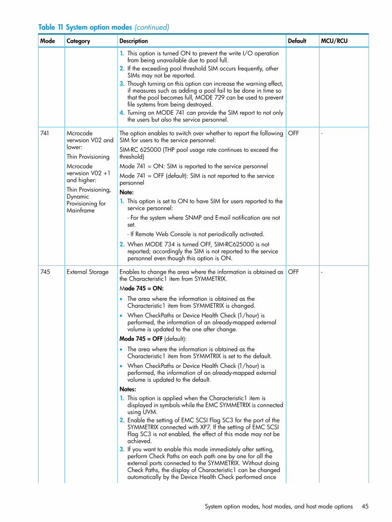
Table 11 System option modes (continued)
MCU/RCUDefaultDescriptionCategoryMode
1. This option is turned ON to prevent the write I/O operationfrom being unavailable due to pool full.
2. If the exceeding pool threshold SIM occurs frequently, otherSIMs may not be reported.
3. Though turning on this option can increase the warning effect,if measures such as adding a pool fail to be done in time sothat the pool becomes full, MODE 729 can be used to preventfile systems from being destroyed.
4. Turning on MODE 741 can provide the SIM report to not onlythe users but also the service personnel.
-OFFThe option enables to switch over whether to report the followingSIM for users to the service personnel:
Mcrocodeverwsion V02 andlower:
741
SIM-RC 625000 (THP pool usage rate continues to exceed thethreshold)Thin ProvisioningMode 741 = ON: SIM is reported to the service personnelMcrocode
verwsion V02 +1and higher:
Mode 741 = OFF (default): SIM is not reported to the servicepersonnel
Thin Provisioning,Dynamic
Note:1. This option is set to ON to have SIM for users reported to the
service personnel:- For the system where SNMP and E-mail notification are notset.
Provisioning forMainframe
- If Remote Web Console is not periodically activated.
2. When MODE 734 is turned OFF, SIM-RC625000 is notreported; accordingly the SIM is not reported to the servicepersonnel even though this option is ON.
-OFFEnables to change the area where the information is obtained asthe Characteristic1 item from SYMMETRIX.
External Storage745
Mode 745 = ON:
• The area where the information is obtained as theCharacteristic1 item from SYMMETRIX is changed.
• When CheckPaths or Device Health Check (1/hour) isperformed, the information of an already-mapped externalvolume is updated to the one after change.
Mode 745 = OFF (default):
• The area where the information is obtained as theCharacteristic1 item from SYMMTRIX is set to the default.
• When CheckPaths or Device Health Check (1/hour) isperformed, the information of an already-mapped externalvolume is updated to the default.
Notes:1. This option is applied when the Characteristic1 item is
displayed in symbols while the EMC SYMMETRIX is connectedusing UVM.
2. Enable the setting of EMC SCSI Flag SC3 for the port of theSYMMETRIX connected with XP7. If the setting of EMC SCSIFlag SC3 is not enabled, the effect of this mode may not beachieved.
3. If you want to enable this mode immediately after setting,perform Check Paths on each path one by one for all theexternal ports connected to the SYMMETRIX. Without doingCheck Paths, the display of Characteristic1 can be changedautomatically by the Device Health Check performed once
System option modes, host modes, and host mode options 45
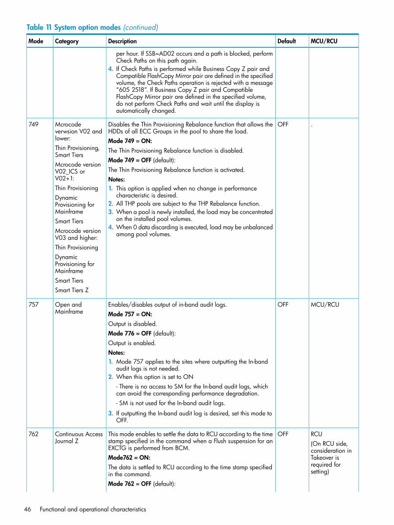
Table 11 System option modes (continued)
MCU/RCUDefaultDescriptionCategoryMode
per hour. If SSB=AD02 occurs and a path is blocked, performCheck Paths on this path again.
4. If Check Paths is performed while Business Copy Z pair andCompatible FlashCopy Mirror pair are defined in the specifiedvolume, the Check Paths operation is rejected with a message“605 2518”. If Business Copy Z pair and CompatibleFlashCopy Mirror pair are defined in the specified volume,do not perform Check Paths and wait until the display isautomatically changed.
.OFFDisables the Thin Provisioning Rebalance function that allows theHDDs of all ECC Groups in the pool to share the load.
Mcrocodeverwsion V02 andlower:
749
Mode 749 = ON:Thin Provisioning,Smart Tiers
The Thin Provisioning Rebalance function is disabled.Mode 749 = OFF (default):
Mcrocode versionV02_ICS orV02+1:
The Thin Provisioning Rebalance function is activated.Notes:
Thin Provisioning 1. This option is applied when no change in performancecharacteristic is desired.Dynamic
Provisioning forMainframe
2. All THP pools are subject to the THP Rebalance function.3. When a pool is newly installed, the load may be concentrated
on the installed pool volumes.Smart Tiers4. When 0 data discarding is executed, load may be unbalanced
among pool volumes.Mcrocode versionV03 and higher:Thin ProvisioningDynamicProvisioning forMainframeSmart TiersSmart Tiers Z
MCU/RCUOFFEnables/disables output of in-band audit logs.Open andMainframe
757Mode 757 = ON:Output is disabled.Mode 776 = OFF (default):Output is enabled.Notes:1. Mode 757 applies to the sites where outputting the In-band
audit logs is not needed.2. When this option is set to ON
- There is no access to SM for the In-band audit logs, whichcan avoid the corresponding performance degradation.- SM is not used for the In-band audit logs.
3. If outputting the In-band audit log is desired, set this mode toOFF.
RCUOFFThis mode enables to settle the data to RCU according to the timestamp specified in the command when a Flush suspension for anEXCTG is performed from BCM.
Continuous AccessJournal Z
762(On RCU side,consideration in
Mode762 = ON: Takeover isrequired forsetting)
The data is settled to RCU according to the time stamp specifiedin the command.Mode 762 = OFF (default):
46 Functional and operational characteristics
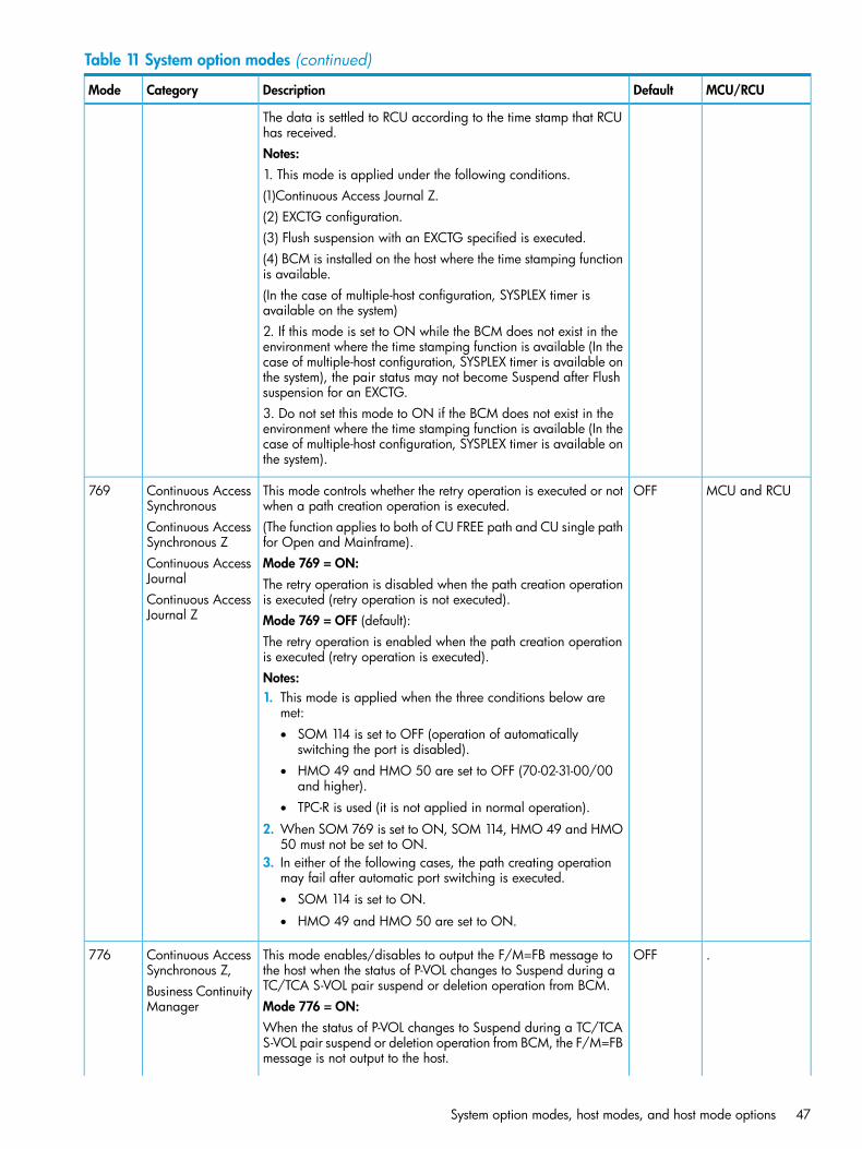
Table 11 System option modes (continued)
MCU/RCUDefaultDescriptionCategoryMode
The data is settled to RCU according to the time stamp that RCUhas received.Notes:1. This mode is applied under the following conditions.(1)Continuous Access Journal Z.(2) EXCTG configuration.(3) Flush suspension with an EXCTG specified is executed.(4) BCM is installed on the host where the time stamping functionis available.(In the case of multiple-host configuration, SYSPLEX timer isavailable on the system)2. If this mode is set to ON while the BCM does not exist in theenvironment where the time stamping function is available (In thecase of multiple-host configuration, SYSPLEX timer is available onthe system), the pair status may not become Suspend after Flushsuspension for an EXCTG.3. Do not set this mode to ON if the BCM does not exist in theenvironment where the time stamping function is available (In thecase of multiple-host configuration, SYSPLEX timer is available onthe system).
MCU and RCUOFFThis mode controls whether the retry operation is executed or notwhen a path creation operation is executed.
Continuous AccessSynchronous
769
(The function applies to both of CU FREE path and CU single pathfor Open and Mainframe).
Continuous AccessSynchronous Z
Mode 769 = ON:Continuous AccessJournal The retry operation is disabled when the path creation operation
is executed (retry operation is not executed).Continuous AccessJournal Z Mode 769 = OFF (default):
The retry operation is enabled when the path creation operationis executed (retry operation is executed).Notes:1. This mode is applied when the three conditions below are
met:• SOM 114 is set to OFF (operation of automatically
switching the port is disabled).• HMO 49 and HMO 50 are set to OFF (70-02-31-00/00
and higher).• TPC-R is used (it is not applied in normal operation).
2. When SOM 769 is set to ON, SOM 114, HMO 49 and HMO50 must not be set to ON.
3. In either of the following cases, the path creating operationmay fail after automatic port switching is executed.• SOM 114 is set to ON.
• HMO 49 and HMO 50 are set to ON.
.OFFThis mode enables/disables to output the F/M=FB message tothe host when the status of P-VOL changes to Suspend during aTC/TCA S-VOL pair suspend or deletion operation from BCM.
Continuous AccessSynchronous Z,Business ContinuityManager
776
Mode 776 = ON:When the status of P-VOL changes to Suspend during a TC/TCAS-VOL pair suspend or deletion operation from BCM, the F/M=FBmessage is not output to the host.
System option modes, host modes, and host mode options 47
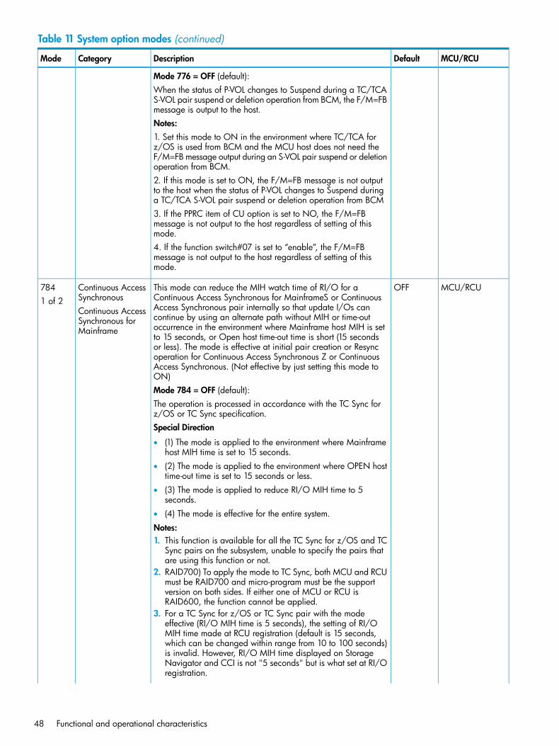
Table 11 System option modes (continued)
MCU/RCUDefaultDescriptionCategoryMode
Mode 776 = OFF (default):When the status of P-VOL changes to Suspend during a TC/TCAS-VOL pair suspend or deletion operation from BCM, the F/M=FBmessage is output to the host.Notes:1. Set this mode to ON in the environment where TC/TCA forz/OS is used from BCM and the MCU host does not need theF/M=FB message output during an S-VOL pair suspend or deletionoperation from BCM.2. If this mode is set to ON, the F/M=FB message is not outputto the host when the status of P-VOL changes to Suspend duringa TC/TCA S-VOL pair suspend or deletion operation from BCM3. If the PPRC item of CU option is set to NO, the F/M=FBmessage is not output to the host regardless of setting of thismode.4. If the function switch#07 is set to “enable”, the F/M=FBmessage is not output to the host regardless of setting of thismode.
MCU/RCUOFFThis mode can reduce the MIH watch time of RI/O for aContinuous Access Synchronous for MainframeS or Continuous
Continuous AccessSynchronous
7841 of 2
Access Synchronous pair internally so that update I/Os canContinuous AccessSynchronous forMainframe
continue by using an alternate path without MIH or time-outoccurrence in the environment where Mainframe host MIH is setto 15 seconds, or Open host time-out time is short (15 secondsor less). The mode is effective at initial pair creation or Resyncoperation for Continuous Access Synchronous Z or ContinuousAccess Synchronous. (Not effective by just setting this mode toON)Mode 784 = OFF (default):The operation is processed in accordance with the TC Sync forz/OS or TC Sync specification.Special Direction
• (1) The mode is applied to the environment where Mainframehost MIH time is set to 15 seconds.
• (2) The mode is applied to the environment where OPEN hosttime-out time is set to 15 seconds or less.
• (3) The mode is applied to reduce RI/O MIH time to 5seconds.
• (4) The mode is effective for the entire system.
Notes:1. This function is available for all the TC Sync for z/OS and TC
Sync pairs on the subsystem, unable to specify the pairs thatare using this function or not.
2. RAID700) To apply the mode to TC Sync, both MCU and RCUmust be RAID700 and micro-program must be the supportversion on both sides. If either one of MCU or RCU isRAID600, the function cannot be applied.
3. For a TC Sync for z/OS or TC Sync pair with the modeeffective (RI/O MIH time is 5 seconds), the setting of RI/OMIH time made at RCU registration (default is 15 seconds,which can be changed within range from 10 to 100 seconds)is invalid. However, RI/O MIH time displayed on StorageNavigator and CCI is not "5 seconds" but is what set at RI/Oregistration.
48 Functional and operational characteristics
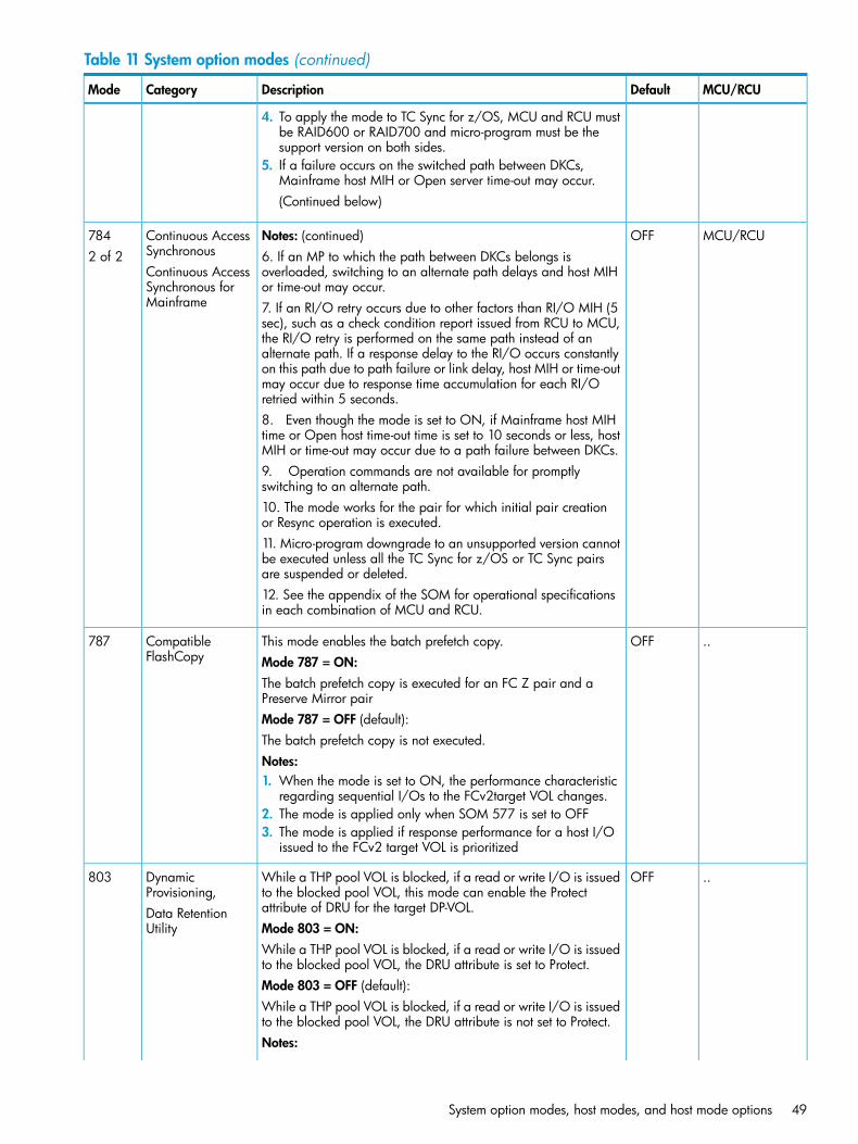
Table 11 System option modes (continued)
MCU/RCUDefaultDescriptionCategoryMode
4. To apply the mode to TC Sync for z/OS, MCU and RCU mustbe RAID600 or RAID700 and micro-program must be thesupport version on both sides.
5. If a failure occurs on the switched path between DKCs,Mainframe host MIH or Open server time-out may occur.(Continued below)
MCU/RCUOFFNotes: (continued)Continuous AccessSynchronous
7842 of 2 6. If an MP to which the path between DKCs belongs is
overloaded, switching to an alternate path delays and host MIHor time-out may occur.
Continuous AccessSynchronous forMainframe 7. If an RI/O retry occurs due to other factors than RI/O MIH (5
sec), such as a check condition report issued from RCU to MCU,the RI/O retry is performed on the same path instead of analternate path. If a response delay to the RI/O occurs constantlyon this path due to path failure or link delay, host MIH or time-outmay occur due to response time accumulation for each RI/Oretried within 5 seconds.8. Even though the mode is set to ON, if Mainframe host MIHtime or Open host time-out time is set to 10 seconds or less, hostMIH or time-out may occur due to a path failure between DKCs.9. Operation commands are not available for promptlyswitching to an alternate path.10. The mode works for the pair for which initial pair creationor Resync operation is executed.11. Micro-program downgrade to an unsupported version cannotbe executed unless all the TC Sync for z/OS or TC Sync pairsare suspended or deleted.12. See the appendix of the SOM for operational specificationsin each combination of MCU and RCU.
..OFFThis mode enables the batch prefetch copy.CompatibleFlashCopy
787Mode 787 = ON:The batch prefetch copy is executed for an FC Z pair and aPreserve Mirror pairMode 787 = OFF (default):The batch prefetch copy is not executed.Notes:1. When the mode is set to ON, the performance characteristic
regarding sequential I/Os to the FCv2target VOL changes.2. The mode is applied only when SOM 577 is set to OFF3. The mode is applied if response performance for a host I/O
issued to the FCv2 target VOL is prioritized
..OFFWhile a THP pool VOL is blocked, if a read or write I/O is issuedto the blocked pool VOL, this mode can enable the Protectattribute of DRU for the target DP-VOL.
DynamicProvisioning,Data RetentionUtility
803
Mode 803 = ON:While a THP pool VOL is blocked, if a read or write I/O is issuedto the blocked pool VOL, the DRU attribute is set to Protect.Mode 803 = OFF (default):While a THP pool VOL is blocked, if a read or write I/O is issuedto the blocked pool VOL, the DRU attribute is not set to Protect.Notes:
System option modes, host modes, and host mode options 49
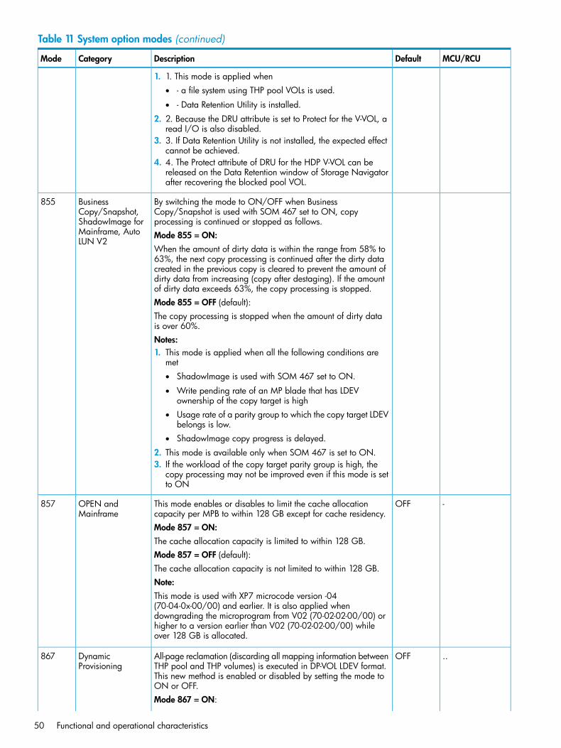
Table 11 System option modes (continued)
MCU/RCUDefaultDescriptionCategoryMode
1. 1. This mode is applied when• - a file system using THP pool VOLs is used.
• - Data Retention Utility is installed.
2. 2. Because the DRU attribute is set to Protect for the V-VOL, aread I/O is also disabled.
3. 3. If Data Retention Utility is not installed, the expected effectcannot be achieved.
4. 4. The Protect attribute of DRU for the HDP V-VOL can bereleased on the Data Retention window of Storage Navigatorafter recovering the blocked pool VOL.
By switching the mode to ON/OFF when BusinessCopy/Snapshot is used with SOM 467 set to ON, copyprocessing is continued or stopped as follows.
BusinessCopy/Snapshot,ShadowImage for
855
Mode 855 = ON:Mainframe, AutoLUN V2
When the amount of dirty data is within the range from 58% to63%, the next copy processing is continued after the dirty datacreated in the previous copy is cleared to prevent the amount ofdirty data from increasing (copy after destaging). If the amountof dirty data exceeds 63%, the copy processing is stopped.Mode 855 = OFF (default):The copy processing is stopped when the amount of dirty datais over 60%.Notes:1. This mode is applied when all the following conditions are
met• ShadowImage is used with SOM 467 set to ON.
• Write pending rate of an MP blade that has LDEVownership of the copy target is high
• Usage rate of a parity group to which the copy target LDEVbelongs is low.
• ShadowImage copy progress is delayed.
2. This mode is available only when SOM 467 is set to ON.3. If the workload of the copy target parity group is high, the
copy processing may not be improved even if this mode is setto ON
-OFFThis mode enables or disables to limit the cache allocationcapacity per MPB to within 128 GB except for cache residency.
OPEN andMainframe
857
Mode 857 = ON:The cache allocation capacity is limited to within 128 GB.Mode 857 = OFF (default):The cache allocation capacity is not limited to within 128 GB.Note:This mode is used with XP7 microcode version -04(70-04-0x-00/00) and earlier. It is also applied whendowngrading the microprogram from V02 (70-02-02-00/00) orhigher to a version earlier than V02 (70-02-02-00/00) whileover 128 GB is allocated.
..OFFAll-page reclamation (discarding all mapping information betweenTHP pool and THP volumes) is executed in DP-VOL LDEV format.
DynamicProvisioning
867
This new method is enabled or disabled by setting the mode toON or OFF.Mode 867 = ON:
50 Functional and operational characteristics

Table 11 System option modes (continued)
MCU/RCUDefaultDescriptionCategoryMode
LDEV format of the DP-VOL is performed with page reclamation.Mode 867 = OFF (default):LDEV format of the HDP-VOL isperformed with 0 data writing.Notes:1. 1. This mode is applied at recovery after a pool failure.2. 2. Do not change the setting of the mode during DP-VOL
format.3. 3. If the setting of the mode is changed during DP-VOL format,
the change is not reflected to the format of the DP-VOL beingexecuted but the format continues in the same method.
..OFFWhen the mode is applied, the order of data transfer slots isguaranteed at the destaging from XP7 to an external storage.
External Storage872
Mode 872 = ON:The order of data transfer slots from XP7 to an external storageis guaranteed.Mode 872 = OFF (default):The order of data transfer slots from XP7 to an external storageis not guaranteed.In V03 and later versions, the mode is set to ON before shipment.If the micro-program is exchanged to a supported version (V03or later), the setting is OFF as default and needs to be set to ONmanually.Note:1. This mode is applied when performance improvement atsequential write in UVM configuration is required.
OFFBy disabling context switch during data transfer, response timein low I/O load is improved.
Mainframe894
Mode 894 = ON:When all the following conditions are met, the context switch isdisabled during data transfer.1. The average MP operating rate of MP PCB is less than 40 %,
or the MP operating rate is less than 50%.2. Write pending rate is less than 35 %.3. Data transfer length is within 8 KB.4. The time from job initiation is within 1600 ?sMode 894 = OFF (default):The context switch is enabled during data transfer.Notes:1. This mode is applied when improvement of I/O response
performance in low workload is required.2. Because the processing on the Mainframe target port is
prioritized, other processing may take longer time comparedto that when the mode is set to OFF.
..OFFSetting the mode to ON or OFF, the link type with transfer speedof 8 GBps or 4 GBps is reported respectively.
Continuous AccessSynchronous Z
895
Mode 895 = ON:When the FICON/FC link up speed is 8 GBps, the link type withtransfer speed of 8 GBps is reported.Mode 895 = OFF (default):The link type with transfer speed of up to 4 GBps is reported ,even when the actual transfer speed is 8 GBps.
System option modes, host modes, and host mode options 51
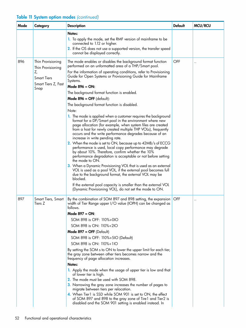
Table 11 System option modes (continued)
MCU/RCUDefaultDescriptionCategoryMode
Notes:1. To apply the mode, set the RMF version of mainframe to be
connected to 1.12 or higher.2. If the OS does not use a supported version, the transfer speed
cannot be displayed correctly.
..OFFThe mode enables or disables the background format functionperformed on an unformatted area of a THP/Smart pool.
Thin ProvisioningThin ProvisioningZ,
896
For the information of operating conditions, refer to ProvisioningGuide for Open Systems or Provisioning Guide for MainframeSystems.
Smart TiersSmart Tiers Z, FastSnap Mode 896 = ON:
The background format function is enabled.Mode 896 = OFF (default):The background format function is disabled.Note:1. The mode is applied when a customer requires the background
format for a DP/Smart pool in the environment where newpage allocation (for example, when system files are createdfrom a host for newly created multiple THP VOLs), frequentlyoccurs and the write performance degrades because of anincrease in write pending rate.
2. When the mode is set to ON, because up to 42MB/s of ECCGperformance is used, local copy performance may degradeby about 10%. Therefore, confirm whether the 10%performance degradation is acceptable or not before settingthe mode to ON.
3. When a Dynamic Provisioning VOL that is used as an externalVOL is used as a pool VOL, if the external pool becomes fulldue to the background format, the external VOL may beblocked.If the external pool capacity is smaller than the external VOL(Dynamic Provisioning VOL), do not set the mode to ON.
..OFFBy the combination of SOM 897 and 898 setting, the expansionwidth of Tier Range upper I/O value (IOPH) can be changed asfollows.
Smart Tiers, SmartTiers Z
897
Mode 897 = ON:SOM 898 is OFF: 110%+0IOSOM 898 is ON: 110%+2IO
Mode 897 = OFF (Default)SOM 898 is OFF: 110%+5IO (Default)SOM 898 is ON: 110%+1IO
By setting the SOM s to ON to lower the upper limit for each tier,the gray zone between other tiers becomes narrow and thefrequency of page allocation increases.Notes:1. Apply the mode when the usage of upper tier is low and that
of lower tier is high.2. The mode must be used with SOM 898.3. Narrowing the gray zone increases the number of pages to
migrate between tiers per relocation.4. When Tier1 is SSD while SOM 901 is set to ON, the effect
of SOM 897 and 898 to the gray zone of Tire1 and Tier2 isdisabled and the SOM 901 setting is enabled instead. In
52 Functional and operational characteristics
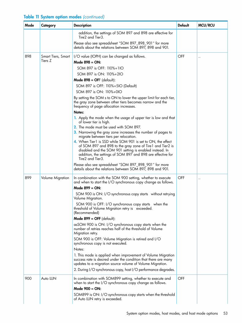
Table 11 System option modes (continued)
MCU/RCUDefaultDescriptionCategoryMode
addition, the settings of SOM 897 and 898 are effective forTire2 and Tier3.
Please also see spreadsheet "SOM 897_898_901" for moredetails about the relations between SOM 897, 898 and 901.
..OFFI/O value (IOPH) can be changed as follows.Smart Tiers, SmartTiers Z
898Mode 898 = ON:
SOM 897 is OFF: 110%+1IOSOM 897 is ON: 110%+2IO
Mode 898 = OFF (default):SOM 897 is OFF: 110%+5IO (Default)SOM 897 is ON: 110%+0IO
By setting the SOM s to ON to lower the upper limit for each tier,the gray zone between other tiers becomes narrow and thefrequency of page allocation increases.Notes:1. Apply the mode when the usage of upper tier is low and that
of lower tier is high.2. The mode must be used with SOM 897.3. Narrowing the gray zone increases the number of pages to
migrate between tiers per relocation.4. When Tier1 is SSD while SOM 901 is set to ON, the effect
of SOM 897 and 898 to the gray zone of Tire1 and Tier2 isdisabled and the SOM 901 setting is enabled instead. Inaddition, the settings of SOM 897 and 898 are effective forTire2 and Tier3.
Please also see spreadsheet "SOM 897_898_901" for moredetails about the relations between SOM 897, 898 and 901.
..OFFIn combination with the SOM 900 setting, whether to executeand when to start the I/O synchronous copy change as follows.
Volume Migration899
Mode 899 = ON:SOM 900 is ON: I/O synchronous copy starts without retrying
Volume Migration.SOM 900 is OFF: I/O synchronous copy starts when the
threshold of Volume Migration retry is exceeded.(Recommended)Mode 899 = OFF (default):asSOM 900 is ON: I/O synchronous copy starts when thenumber of retries reaches half of the threshold of VolumeMigration retry.SOM 900 is OFF: Volume Migration is retired and I/Osynchronous copy is not executed.Notes:1. This mode is applied when improvement of Volume Migrationsuccess rate is desired under the condition that there are manyupdates to a migration source volume of Volume Migration.2. During I/O synchronous copy, host I/O performance degrades.
OFFIn combination with SOM899 setting, whether to execute andwhen to start the I/O synchronous copy change as follows.
Auto LUN900
Mode 900 = ON:SOM899 is ON: I/O synchronous copy starts when the thresholdof Auto LUN retry is exceeded.
System option modes, host modes, and host mode options 53
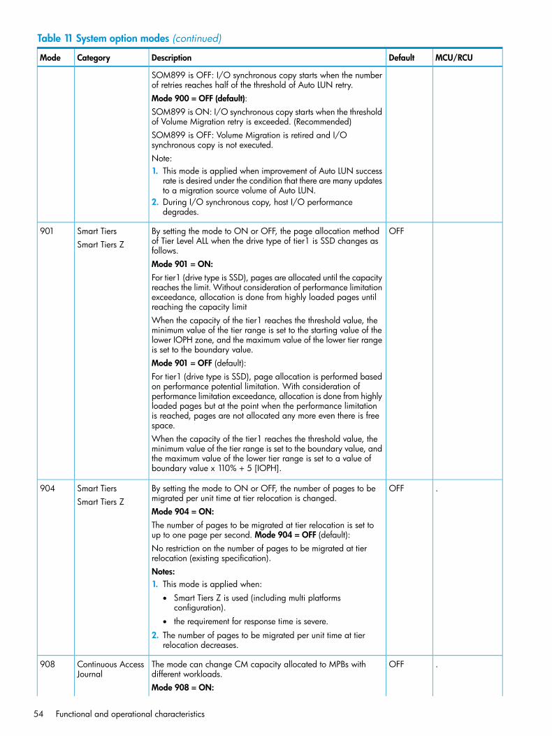
Table 11 System option modes (continued)
MCU/RCUDefaultDescriptionCategoryMode
SOM899 is OFF: I/O synchronous copy starts when the numberof retries reaches half of the threshold of Auto LUN retry.Mode 900 = OFF (default):SOM899 is ON: I/O synchronous copy starts when the thresholdof Volume Migration retry is exceeded. (Recommended)SOM899 is OFF: Volume Migration is retired and I/Osynchronous copy is not executed.Note:1. This mode is applied when improvement of Auto LUN success
rate is desired under the condition that there are many updatesto a migration source volume of Auto LUN.
2. During I/O synchronous copy, host I/O performancedegrades.
OFFBy setting the mode to ON or OFF, the page allocation methodof Tier Level ALL when the drive type of tier1 is SSD changes asfollows.
Smart TiersSmart Tiers Z
901
Mode 901 = ON:For tier1 (drive type is SSD), pages are allocated until the capacityreaches the limit. Without consideration of performance limitationexceedance, allocation is done from highly loaded pages untilreaching the capacity limitWhen the capacity of the tier1 reaches the threshold value, theminimum value of the tier range is set to the starting value of thelower IOPH zone, and the maximum value of the lower tier rangeis set to the boundary value.Mode 901 = OFF (default):For tier1 (drive type is SSD), page allocation is performed basedon performance potential limitation. With consideration ofperformance limitation exceedance, allocation is done from highlyloaded pages but at the point when the performance limitationis reached, pages are not allocated any more even there is freespace.When the capacity of the tier1 reaches the threshold value, theminimum value of the tier range is set to the boundary value, andthe maximum value of the lower tier range is set to a value ofboundary value x 110% + 5 [IOPH].
.OFFBy setting the mode to ON or OFF, the number of pages to bemigrated per unit time at tier relocation is changed.
Smart TiersSmart Tiers Z
904
Mode 904 = ON:The number of pages to be migrated at tier relocation is set toup to one page per second. Mode 904 = OFF (default):No restriction on the number of pages to be migrated at tierrelocation (existing specification).Notes:1. This mode is applied when:
• Smart Tiers Z is used (including multi platformsconfiguration).
• the requirement for response time is severe.
2. The number of pages to be migrated per unit time at tierrelocation decreases.
.OFFThe mode can change CM capacity allocated to MPBs withdifferent workloads.
Continuous AccessJournal
908
Mode 908 = ON:
54 Functional and operational characteristics
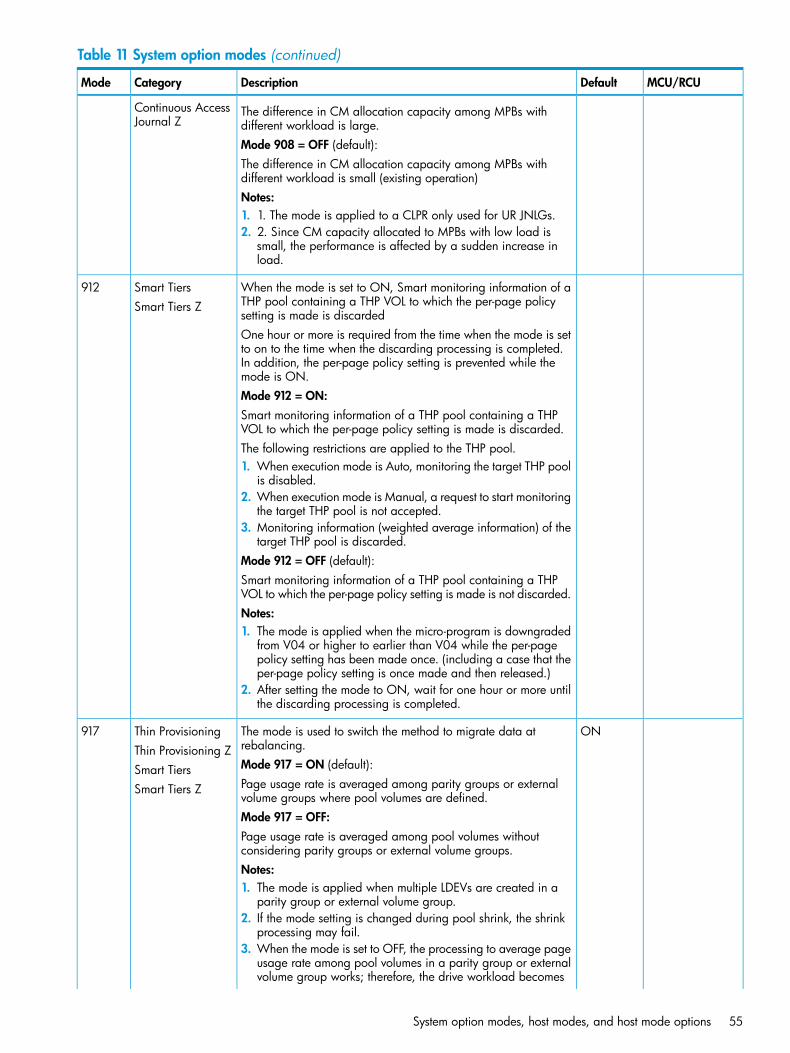
Table 11 System option modes (continued)
MCU/RCUDefaultDescriptionCategoryMode
Continuous AccessJournal Z
The difference in CM allocation capacity among MPBs withdifferent workload is large.Mode 908 = OFF (default):The difference in CM allocation capacity among MPBs withdifferent workload is small (existing operation)Notes:1. 1. The mode is applied to a CLPR only used for UR JNLGs.2. 2. Since CM capacity allocated to MPBs with low load is
small, the performance is affected by a sudden increase inload.
When the mode is set to ON, Smart monitoring information of aTHP pool containing a THP VOL to which the per-page policysetting is made is discarded
Smart TiersSmart Tiers Z
912
One hour or more is required from the time when the mode is setto on to the time when the discarding processing is completed.In addition, the per-page policy setting is prevented while themode is ON.Mode 912 = ON:Smart monitoring information of a THP pool containing a THPVOL to which the per-page policy setting is made is discarded.The following restrictions are applied to the THP pool.1. When execution mode is Auto, monitoring the target THP pool
is disabled.2. When execution mode is Manual, a request to start monitoring
the target THP pool is not accepted.3. Monitoring information (weighted average information) of the
target THP pool is discarded.Mode 912 = OFF (default):Smart monitoring information of a THP pool containing a THPVOL to which the per-page policy setting is made is not discarded.Notes:1. The mode is applied when the micro-program is downgraded
from V04 or higher to earlier than V04 while the per-pagepolicy setting has been made once. (including a case that theper-page policy setting is once made and then released.)
2. After setting the mode to ON, wait for one hour or more untilthe discarding processing is completed.
ONThe mode is used to switch the method to migrate data atrebalancing.
Thin ProvisioningThin Provisioning Z
917
Mode 917 = ON (default):Smart TiersPage usage rate is averaged among parity groups or externalvolume groups where pool volumes are defined.
Smart Tiers Z
Mode 917 = OFF:Page usage rate is averaged among pool volumes withoutconsidering parity groups or external volume groups.Notes:1. The mode is applied when multiple LDEVs are created in a
parity group or external volume group.2. If the mode setting is changed during pool shrink, the shrink
processing may fail.3. When the mode is set to OFF, the processing to average page
usage rate among pool volumes in a parity group or externalvolume group works; therefore, the drive workload becomes
System option modes, host modes, and host mode options 55
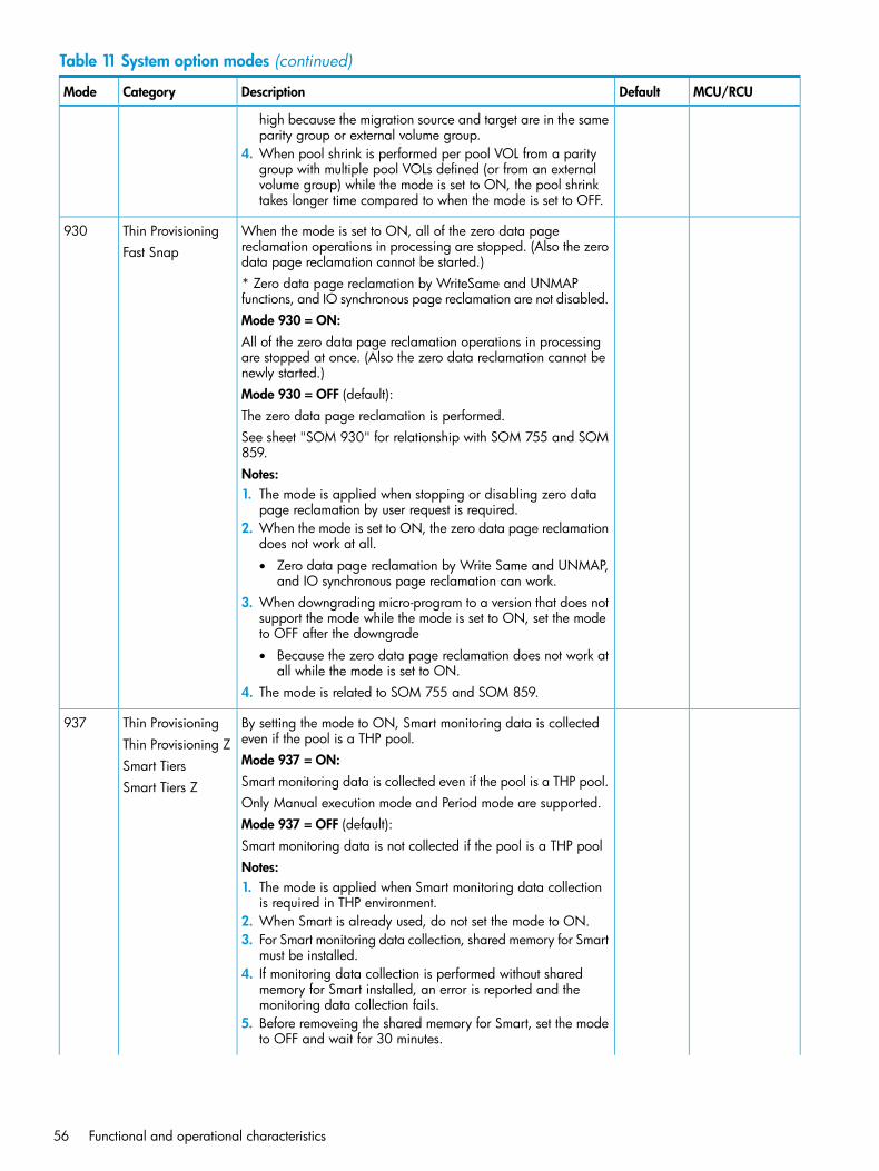
Table 11 System option modes (continued)
MCU/RCUDefaultDescriptionCategoryMode
high because the migration source and target are in the sameparity group or external volume group.
4. When pool shrink is performed per pool VOL from a paritygroup with multiple pool VOLs defined (or from an externalvolume group) while the mode is set to ON, the pool shrinktakes longer time compared to when the mode is set to OFF.
When the mode is set to ON, all of the zero data pagereclamation operations in processing are stopped. (Also the zerodata page reclamation cannot be started.)
Thin ProvisioningFast Snap
930
* Zero data page reclamation by WriteSame and UNMAPfunctions, and IO synchronous page reclamation are not disabled.Mode 930 = ON:All of the zero data page reclamation operations in processingare stopped at once. (Also the zero data reclamation cannot benewly started.)Mode 930 = OFF (default):The zero data page reclamation is performed.See sheet "SOM 930" for relationship with SOM 755 and SOM859.Notes:1. The mode is applied when stopping or disabling zero data
page reclamation by user request is required.2. When the mode is set to ON, the zero data page reclamation
does not work at all.• Zero data page reclamation by Write Same and UNMAP,
and IO synchronous page reclamation can work.3. When downgrading micro-program to a version that does not
support the mode while the mode is set to ON, set the modeto OFF after the downgrade• Because the zero data page reclamation does not work at
all while the mode is set to ON.4. The mode is related to SOM 755 and SOM 859.
By setting the mode to ON, Smart monitoring data is collectedeven if the pool is a THP pool.
Thin ProvisioningThin Provisioning Z
937
Mode 937 = ON:Smart TiersSmart monitoring data is collected even if the pool is a THP pool.Smart Tiers ZOnly Manual execution mode and Period mode are supported.Mode 937 = OFF (default):Smart monitoring data is not collected if the pool is a THP poolNotes:1. The mode is applied when Smart monitoring data collection
is required in THP environment.2. When Smart is already used, do not set the mode to ON.3. For Smart monitoring data collection, shared memory for Smart
must be installed.4. If monitoring data collection is performed without shared
memory for Smart installed, an error is reported and themonitoring data collection fails.
5. Before removeing the shared memory for Smart, set the modeto OFF and wait for 30 minutes.
56 Functional and operational characteristics
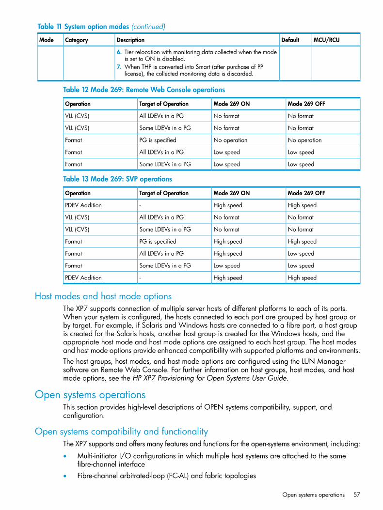
Table 11 System option modes (continued)
MCU/RCUDefaultDescriptionCategoryMode
6. Tier relocation with monitoring data collected when the modeis set to ON is disabled.
7. When THP is converted into Smart (after purchase of PPlicense), the collected monitoring data is discarded.
Table 12 Mode 269: Remote Web Console operations
Mode 269 OFFMode 269 ONTarget of OperationOperation
No formatNo formatAll LDEVs in a PGVLL (CVS)
No formatNo formatSome LDEVs in a PGVLL (CVS)
No operationNo operationPG is specifiedFormat
Low speedLow speedAll LDEVs in a PGFormat
Low speedLow speedSome LDEVs in a PGFormat
Table 13 Mode 269: SVP operations
Mode 269 OFFMode 269 ONTarget of OperationOperation
High speedHigh speed-PDEV Addition
No formatNo formatAll LDEVs in a PGVLL (CVS)
No formatNo formatSome LDEVs in a PGVLL (CVS)
High speedHigh speedPG is specifiedFormat
Low speedHigh speedAll LDEVs in a PGFormat
Low speedLow speedSome LDEVs in a PGFormat
High speedHigh speed-PDEV Addition
Host modes and host mode optionsThe XP7 supports connection of multiple server hosts of different platforms to each of its ports.When your system is configured, the hosts connected to each port are grouped by host group orby target. For example, if Solaris and Windows hosts are connected to a fibre port, a host groupis created for the Solaris hosts, another host group is created for the Windows hosts, and theappropriate host mode and host mode options are assigned to each host group. The host modesand host mode options provide enhanced compatibility with supported platforms and environments.The host groups, host modes, and host mode options are configured using the LUN Managersoftware on Remote Web Console. For further information on host groups, host modes, and hostmode options, see the HP XP7 Provisioning for Open Systems User Guide.
Open systems operationsThis section provides high-level descriptions of OPEN systems compatibility, support, andconfiguration.
Open systems compatibility and functionalityThe XP7 supports and offers many features and functions for the open-systems environment, including:
• Multi-initiator I/O configurations in which multiple host systems are attached to the samefibre-channel interface
• Fibre-channel arbitrated-loop (FC-AL) and fabric topologies
Open systems operations 57
• Command tag queuing
• Industry-standard failover and logical volume management software
• SNMP remote disk array managementThe XP7’s global cache enables any fibre-channel port to have access to any logical unit in thedisk array. In the XP7, each logical unit can be assigned to multiple fibre-channel ports to provideI/O path failover and/or load balancing (with the appropriate middleware support) withoutsacrificing cache coherency.The user should plan for path failover (alternate pathing) to ensure the highest data availability.The logical units can be mapped for access from multiple ports and/or multiple target IDs. Thenumber of connected hosts is limited only by the number of FC ports installed and the requirementfor alternate pathing within each host. If possible, the primary path and alternate paths should beattached to different channel cards.
Open systems host platform supportXP7 Storage supports most major open-system operating systems, such as Microsoft Windows,Oracle Solaris, IBM AIX, Linux, HP-UX, and VMware. For more complete information on thesupported operating systems, go to: http://www.hp.com. Each supported platform has a userguide that is included in the XP7 documentation set. See the HP XP7 Documentation Roadmap fora complete list of XP7 user guides, including the host configuration guides.
Open systems configurationAfter physical installation of XP7 Storage has been completed, the user configures the disk arrayfor open-systems operations with assistance as needed from the HP representative.Please see the following documents for information and instructions on configuring XP7 Storagefor open-systems operations:
• The host configuration guides provide information and instructions on configuring XP7 Storageand disk devices for attachment to the open-systems hosts.
NOTE: Queue depth and other parameters may need to be adjusted for the disk array. Seethe appropriate configuration guide for queue depth and other requirements.
• The HP XP7 Remote Web Console User Guide provides instructions for installing, configuring,and using Remote Web Console to perform resource and data management operations onXP7 Storage.
• The HP XP7 Provisioning for Open Systems User Guide describes and provides instructionsfor configuring the XP7 for host operations, including FC port configuration, LUN mapping,host groups, host modes and host mode options, and LUN Security.Each fibre-channel port on XP7 Storage provides addressing capabilities for up to 2,048LUNs across as many as 255 host groups, each with its own LUN 0, host mode, and hostmode options. Multiple host groups are supported using LUN Security.
• The HP XP7 SNMP Agent User Guide describes the SNMP API interface for XP7 Storage andprovides instructions for configuring and performing SNMP operations.
• The HP XP7 Provisioning for Open Systems User Guide and HP XP7 Volume Shredder forOpen and Mainframe Systems User Guide provide instructions for configuring multiple customvolumes (logical units) under single LDEVs on XP7 Storage. The HP XP7 Provisioning for OpenSystems User Guide also provides instructions for configuring size-expanded logical units byconcatenating multiple logical units to form individual large logical units.
58 Functional and operational characteristics
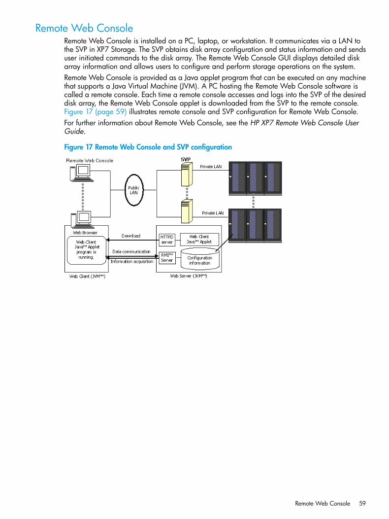
Remote Web ConsoleRemote Web Console is installed on a PC, laptop, or workstation. It communicates via a LAN tothe SVP in XP7 Storage. The SVP obtains disk array configuration and status information and sendsuser initiated commands to the disk array. The Remote Web Console GUI displays detailed diskarray information and allows users to configure and perform storage operations on the system.Remote Web Console is provided as a Java applet program that can be executed on any machinethat supports a Java Virtual Machine (JVM). A PC hosting the Remote Web Console software iscalled a remote console. Each time a remote console accesses and logs into the SVP of the desireddisk array, the Remote Web Console applet is downloaded from the SVP to the remote console.Figure 17 (page 59) illustrates remote console and SVP configuration for Remote Web Console.For further information about Remote Web Console, see the HP XP7 Remote Web Console UserGuide.
Figure 17 Remote Web Console and SVP configuration
Remote Web Console 59
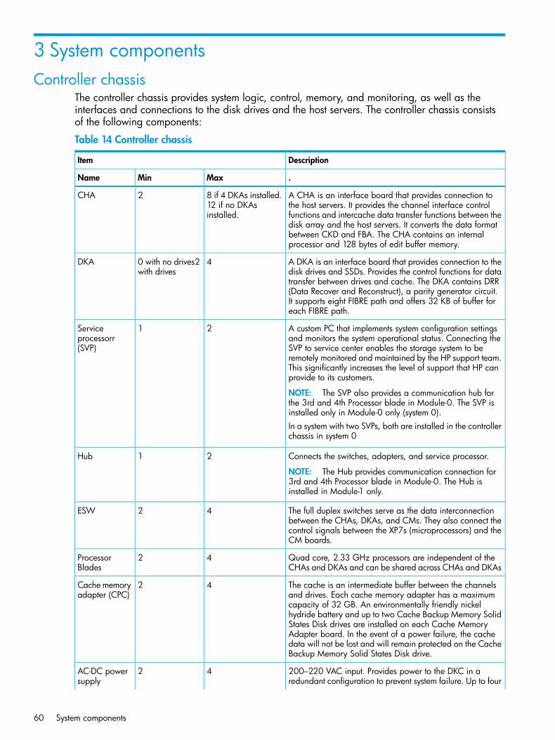
3 System componentsController chassis
The controller chassis provides system logic, control, memory, and monitoring, as well as theinterfaces and connections to the disk drives and the host servers. The controller chassis consistsof the following components:
Table 14 Controller chassis
DescriptionItem
.MaxMinName
A CHA is an interface board that provides connection tothe host servers. It provides the channel interface control
8 if 4 DKAs installed.12 if no DKAsinstalled.
2CHA
functions and intercache data transfer functions between thedisk array and the host servers. It converts the data formatbetween CKD and FBA. The CHA contains an internalprocessor and 128 bytes of edit buffer memory.
A DKA is an interface board that provides connection to thedisk drives and SSDs. Provides the control functions for data
40 with no drives2with drives
DKA
transfer between drives and cache. The DKA contains DRR(Data Recover and Reconstruct), a parity generator circuit.It supports eight FIBRE path and offers 32 KB of buffer foreach FIBRE path.
A custom PC that implements system configuration settingsand monitors the system operational status. Connecting the
21Serviceprocessorr(SVP) SVP to service center enables the storage system to be
remotely monitored and maintained by the HP support team.This significantly increases the level of support that HP canprovide to its customers.
NOTE: The SVP also provides a communication hub forthe 3rd and 4th Processor blade in Module-0. The SVP isinstalled only in Module-0 only (system 0).In a system with two SVPs, both are installed in the controllerchassis in system 0
Connects the switches, adapters, and service processor.
NOTE: The Hub provides communication connection for3rd and 4th Processor blade in Module-0. The Hub isinstalled in Module-1 only.
21Hub
The full duplex switches serve as the data interconnectionbetween the CHAs, DKAs, and CMs. They also connect the
42ESW
control signals between the XP7s (microprocessors) and theCM boards.
Quad core, 2.33 GHz processors are independent of theCHAs and DKAs and can be shared across CHAs and DKAs
42ProcessorBlades
The cache is an intermediate buffer between the channelsand drives. Each cache memory adapter has a maximum
42Cache memoryadapter (CPC)
capacity of 32 GB. An environmentally friendly nickelhydride battery and up to two Cache Backup Memory SolidStates Disk drives are installed on each Cache MemoryAdapter board. In the event of a power failure, the cachedata will not be lost and will remain protected on the CacheBackup Memory Solid States Disk drive.
200–220 VAC input. Provides power to the DKC in aredundant configuration to prevent system failure. Up to four
42AC-DC powersupply
60 System components
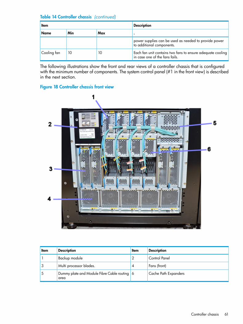
Table 14 Controller chassis (continued)
DescriptionItem
.MaxMinName
power supplies can be used as needed to provide powerto additional components.
Each fan unit contains two fans to ensure adequate coolingin case one of the fans fails.
1010Cooling fan
The following illustrations show the front and rear views of a controller chassis that is configuredwith the minimum number of components. The system control panel (#1 in the front view) is describedin the next section.
Figure 18 Controller chassis front view
DescriptionItemDescriptionItem
Control Panel2Backup module1
Fans (front)4Multi processor blades.3
Cache Path Expanders6Dummy plate and Module Fibre Cable routingarea
5
Controller chassis 61
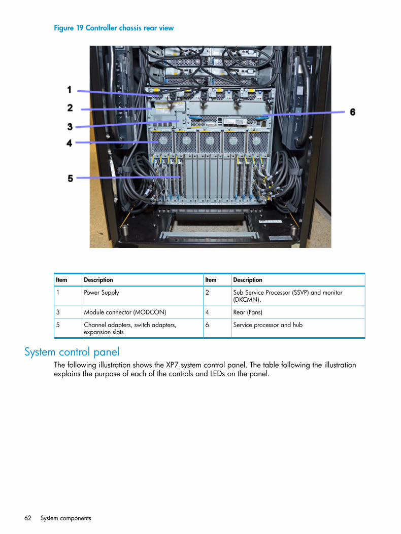
Figure 19 Controller chassis rear view
DescriptionItemDescriptionItem
Sub Service Processor (SSVP) and monitor(DKCMN).
2Power Supply1
Rear (Fans)4Module connector (MODCON)3
Service processor and hub6Channel adapters, switch adapters,expansion slots
5
System control panelThe following illustration shows the XP7 system control panel. The table following the illustrationexplains the purpose of each of the controls and LEDs on the panel.
62 System components
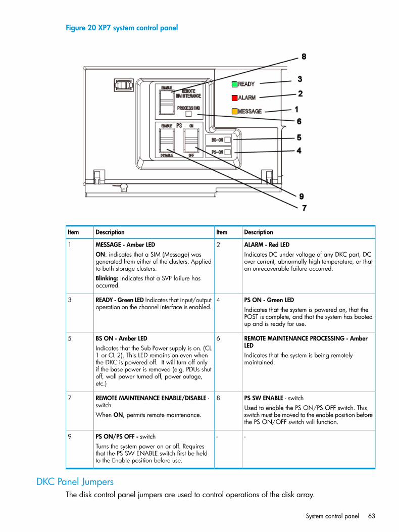
Figure 20 XP7 system control panel
DescriptionItemDescriptionItem
ALARM - Red LED2MESSAGE - Amber LED1Indicates DC under voltage of any DKC part, DCover current, abnormally high temperature, or thatan unrecoverable failure occurred.
ON: indicates that a SIM (Message) wasgenerated from either of the clusters. Appliedto both storage clusters.Blinking: Indicates that a SVP failure hasoccurred.
PS ON - Green LED4READY - Green LED Indicates that input/outputoperation on the channel interface is enabled.
3Indicates that the system is powered on, that thePOST is complete, and that the system has bootedup and is ready for use.
REMOTE MAINTENANCE PROCESSING - AmberLED
6BS ON - Amber LEDIndicates that the Sub Power supply is on. (CL1 or CL 2). This LED remains on even when
5
Indicates that the system is being remotelymaintained.the DKC is powered off. It will turn off only
if the base power is removed (e.g. PDUs shutoff, wall power turned off, power outage,etc.)
PS SW ENABLE - switch8REMOTE MAINTENANCE ENABLE/DISABLE -switch
7Used to enable the PS ON/PS OFF switch. Thisswitch must be moved to the enable position beforethe PS ON/OFF switch will function.
When ON, permits remote maintenance.
--PS ON/PS OFF - switch9Turns the system power on or off. Requiresthat the PS SW ENABLE switch first be heldto the Enable position before use.
DKC Panel JumpersThe disk control panel jumpers are used to control operations of the disk array.
System control panel 63
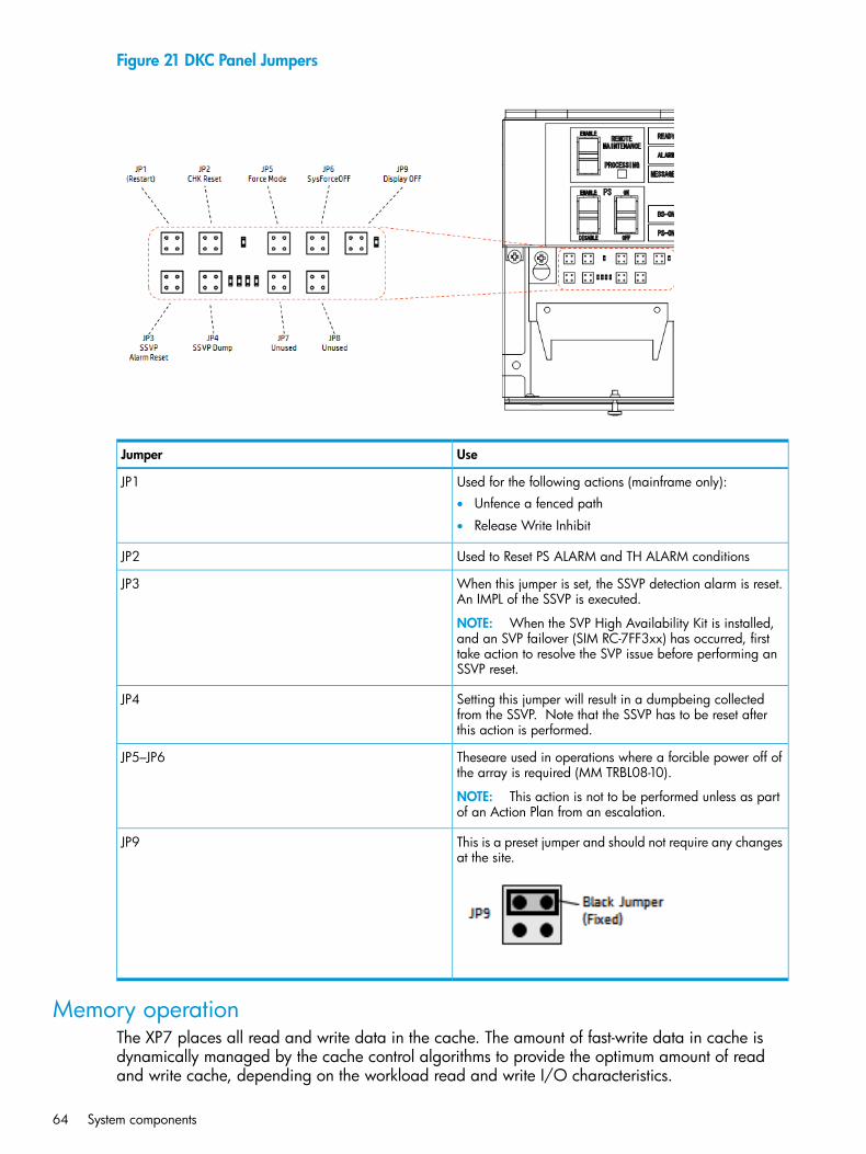
Figure 21 DKC Panel Jumpers
UseJumper
Used for the following actions (mainframe only):JP1• Unfence a fenced path
• Release Write Inhibit
Used to Reset PS ALARM and TH ALARM conditionsJP2
When this jumper is set, the SSVP detection alarm is reset.An IMPL of the SSVP is executed.
NOTE: When the SVP High Availability Kit is installed,and an SVP failover (SIM RC-7FF3xx) has occurred, firsttake action to resolve the SVP issue before performing anSSVP reset.
JP3
Setting this jumper will result in a dumpbeing collectedfrom the SSVP. Note that the SSVP has to be reset afterthis action is performed.
JP4
Theseare used in operations where a forcible power off ofthe array is required (MM TRBL08-10).
NOTE: This action is not to be performed unless as partof an Action Plan from an escalation.
JP5–JP6
This is a preset jumper and should not require any changesat the site.
JP9
Memory operationThe XP7 places all read and write data in the cache. The amount of fast-write data in cache isdynamically managed by the cache control algorithms to provide the optimum amount of readand write cache, depending on the workload read and write I/O characteristics.
64 System components
Mainframe hosts can specify special attributes (for example, cache fast write command) to writedata (typically sort work data) without write duplexing. This data is not duplexed and is usuallygiven a discard command at the end of the sort, so that the data will not be destaged to the drives.
Data protectionThe XP7 is designed so that it cannot lose data or configuration information from the cache if thepower fails. The cache is protected from data loss up for up to ten minutes by the cache destagebatteries while the data is copied to the cache SSD (flash memory) on the cache boards (see“Battery backup operations” (page 72)).
Shared memoryThe XP7 shared memory is not on a separate memory module as it was in the previous hardwaresystems. Shared memory resides by default on the first pair of cache boards in controller chassis#0.When you install software features such as Snapshot or Continuous Access Journal, the sharedmemory usage increases as software features are installed. Shared memory can use up to 56 GB.Depending on how much cache memory is installed, it may be necessary to install more cachememory as more software features are installed in the system. Up to 32 GB can be installed oneach cache board. When 32 GB of cache is installed, it is also necessary to install a second SSD(cache flash memory) on the cache board to back up the cache in case of power failure. Additionalcache backup SSD memory comes in 32 and 64 GB capacities.In addition to cache, the shared memory on each cache board contains a 1/2 GB cache directoryto safeguard write pending data in the cache in the unlikely case of double failure of the sharedmemory cache area. The cache directory has mapping tables for the Micro Processor Blade LDEVsand the allocated cache slots in each Micro Processor Blade cache partition.
NOTE: Shared Memory in the P9000 is not a separate memory module as it was in the HPXP24000/20000 disk arrays.
Flash storage chassisThis section includes information on the flash module drive (FMD), flash storage unit (FSU), andflash storage chassis (FSX).
XP7 flash moduleThe XP7 flash module is a custom-designed and manufactured enterprise class solid state storagemodule. It uses a high performance, custom ASIC flash controller and standard flash memory chipsin an implementation that exceeds the performance of expensive SLC SSDs, but costs less than lessexpensive MLC SSDs. The FMD greatly improves the performance and solid state storage capacityof the VSP system, while significantly reducing the cost per TB of storage.Even in the initial capacity of 1.6 TB per FMD, the FMD outperforms both MLC and SLC flashdrives, has a longer service life, requires less power, and generates less heat per TB than SSDs.FMDs can be used instead of, or in addition to, disk and flash drives, but they are installed in aflash storage “chassis” composed of a cluster four flash module units (FMU). The next sectiondescribes the FMU.
Data protection 65
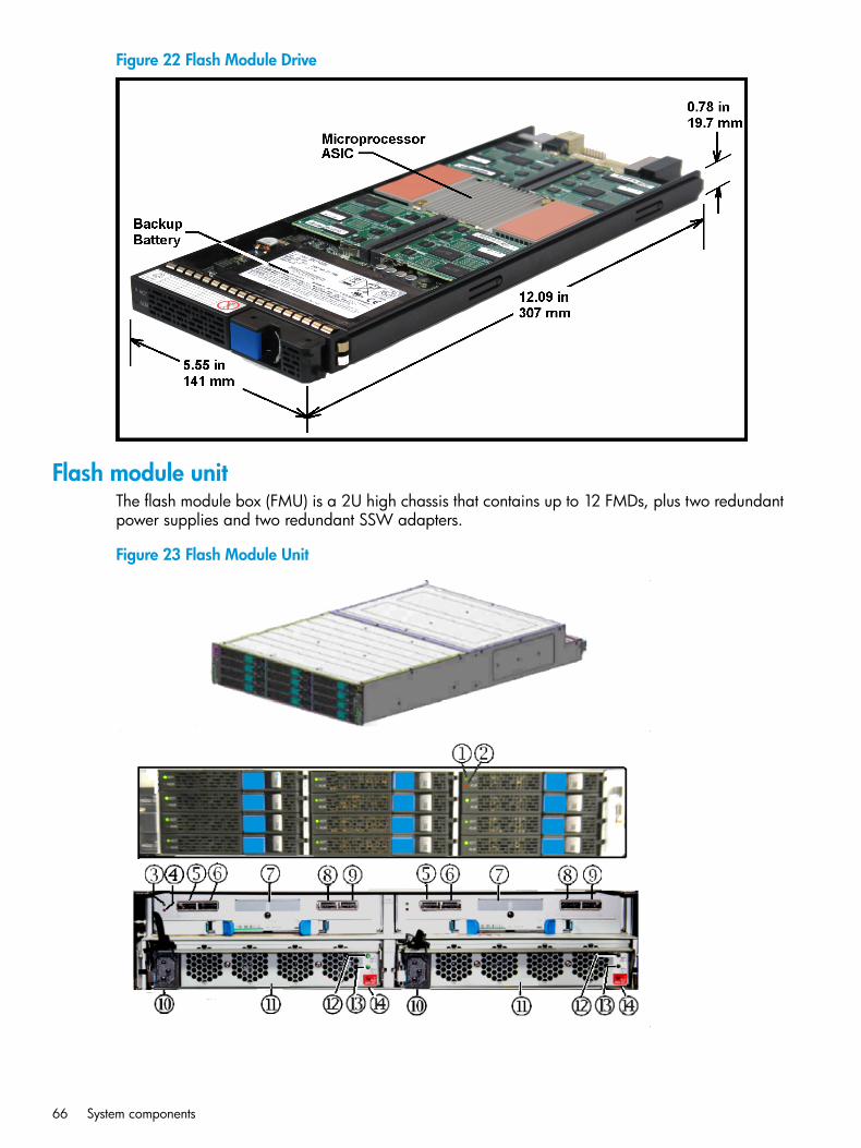
Figure 22 Flash Module Drive
Flash module unitThe flash module box (FMU) is a 2U high chassis that contains up to 12 FMDs, plus two redundantpower supplies and two redundant SSW adapters.
Figure 23 Flash Module Unit
66 System components
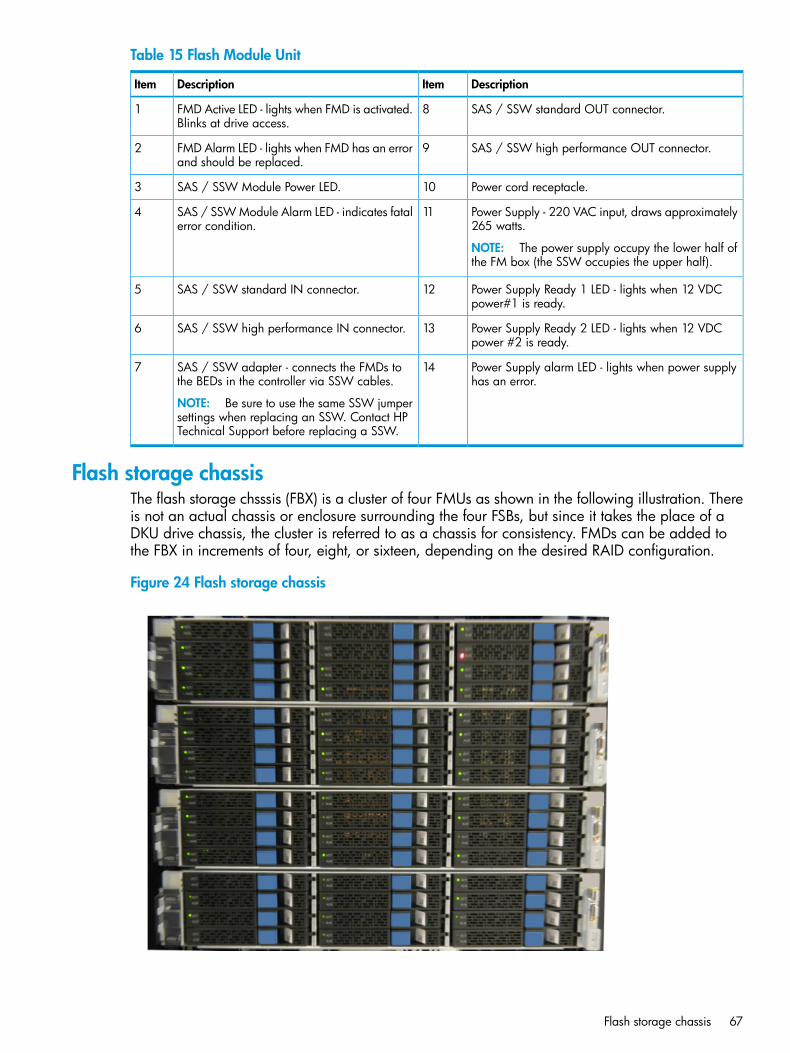
Table 15 Flash Module Unit
DescriptionItemDescriptionItem
SAS / SSW standard OUT connector.8FMD Active LED - lights when FMD is activated.Blinks at drive access.
1
SAS / SSW high performance OUT connector.9FMD Alarm LED - lights when FMD has an errorand should be replaced.
2
Power cord receptacle.10SAS / SSW Module Power LED.3
Power Supply - 220 VAC input, draws approximately265 watts.
NOTE: The power supply occupy the lower half ofthe FM box (the SSW occupies the upper half).
11SAS / SSW Module Alarm LED - indicates fatalerror condition.
4
Power Supply Ready 1 LED - lights when 12 VDCpower#1 is ready.
12SAS / SSW standard IN connector.5
Power Supply Ready 2 LED - lights when 12 VDCpower #2 is ready.
13SAS / SSW high performance IN connector.6
Power Supply alarm LED - lights when power supplyhas an error.
14SAS / SSW adapter - connects the FMDs tothe BEDs in the controller via SSW cables.
NOTE: Be sure to use the same SSW jumpersettings when replacing an SSW. Contact HPTechnical Support before replacing a SSW.
7
Flash storage chassisThe flash storage chsssis (FBX) is a cluster of four FMUs as shown in the following illustration. Thereis not an actual chassis or enclosure surrounding the four FSBs, but since it takes the place of aDKU drive chassis, the cluster is referred to as a chassis for consistency. FMDs can be added tothe FBX in increments of four, eight, or sixteen, depending on the desired RAID configuration.
Figure 24 Flash storage chassis
Flash storage chassis 67
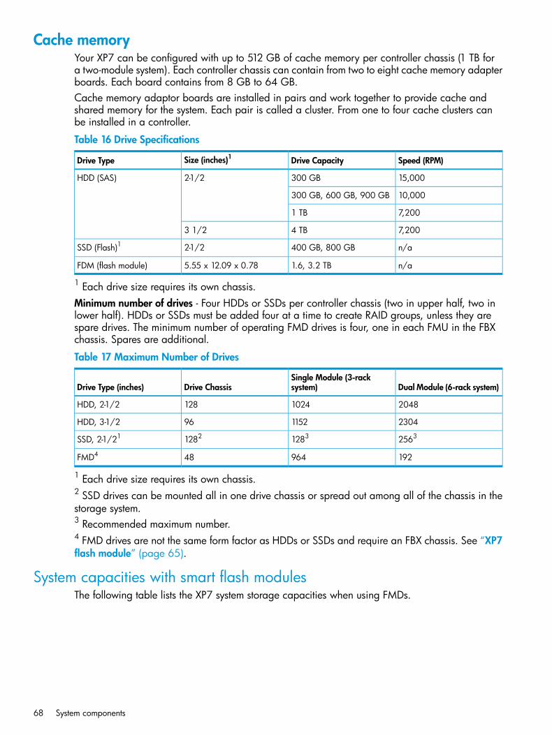
Cache memoryYour XP7 can be configured with up to 512 GB of cache memory per controller chassis (1 TB fora two-module system). Each controller chassis can contain from two to eight cache memory adapterboards. Each board contains from 8 GB to 64 GB.Cache memory adaptor boards are installed in pairs and work together to provide cache andshared memory for the system. Each pair is called a cluster. From one to four cache clusters canbe installed in a controller.
Table 16 Drive Specifications
Speed (RPM)Drive CapacitySize (inches)1Drive Type
15,000300 GB2-1/2HDD (SAS)
10,000300 GB, 600 GB, 900 GB
7,2001 TB
7,2004 TB3 1/2
n/a400 GB, 800 GB2-1/2SSD (Flash)1
n/a1.6, 3.2 TB5.55 x 12.09 x 0.78FDM (flash module)
1 Each drive size requires its own chassis.Minimum number of drives - Four HDDs or SSDs per controller chassis (two in upper half, two inlower half). HDDs or SSDs must be added four at a time to create RAID groups, unless they arespare drives. The minimum number of operating FMD drives is four, one in each FMU in the FBXchassis. Spares are additional.
Table 17 Maximum Number of Drives
Dual Module (6-rack system)Single Module (3-racksystem)Drive ChassisDrive Type (inches)
20481024128HDD, 2-1/2
2304115296HDD, 3-1/2
256312831282SSD, 2-1/21
19296448FMD4
1 Each drive size requires its own chassis.2 SSD drives can be mounted all in one drive chassis or spread out among all of the chassis in thestorage system.3 Recommended maximum number.4 FMD drives are not the same form factor as HDDs or SSDs and require an FBX chassis. See “XP7flash module” (page 65).
System capacities with smart flash modulesThe following table lists the XP7 system storage capacities when using FMDs.
68 System components
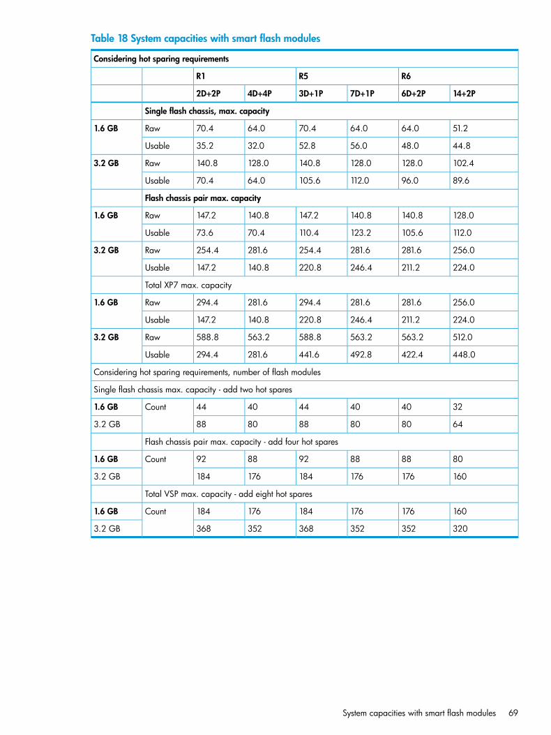
Table 18 System capacities with smart flash modules
Considering hot sparing requirements
R6R5R1
14+2P6D+2P7D+1P3D+1P4D+4P2D+2P
Single flash chassis, max. capacity
51.264.064.070.464.070.4Raw1.6 GB
44.848.056.052.832.035.2Usable
102.4128.0128.0140.8128.0140.8Raw3.2 GB
89.696.0112.0105.664.070.4Usable
Flash chassis pair max. capacity
128.0140.8140.8147.2140.8147.2Raw1.6 GB
112.0105.6123.2110.470.473.6Usable
256.0281.6281.6254.4281.6254.4Raw3.2 GB
224.0211.2246.4220.8140.8147.2Usable
Total XP7 max. capacity
256.0281.6281.6294.4281.6294.4Raw1.6 GB
224.0211.2246.4220.8140.8147.2Usable
512.0563.2563.2588.8563.2588.8Raw3.2 GB
448.0422.4492.8441.6281.6294.4Usable
Considering hot sparing requirements, number of flash modules
Single flash chassis max. capacity - add two hot spares
324040444044Count1.6 GB
6480808880883.2 GB
Flash chassis pair max. capacity - add four hot spares
808888928892Count1.6 GB
1601761761841761843.2 GB
Total VSP max. capacity - add eight hot spares
160176176184176184Count1.6 GB
3203523523683523683.2 GB
System capacities with smart flash modules 69
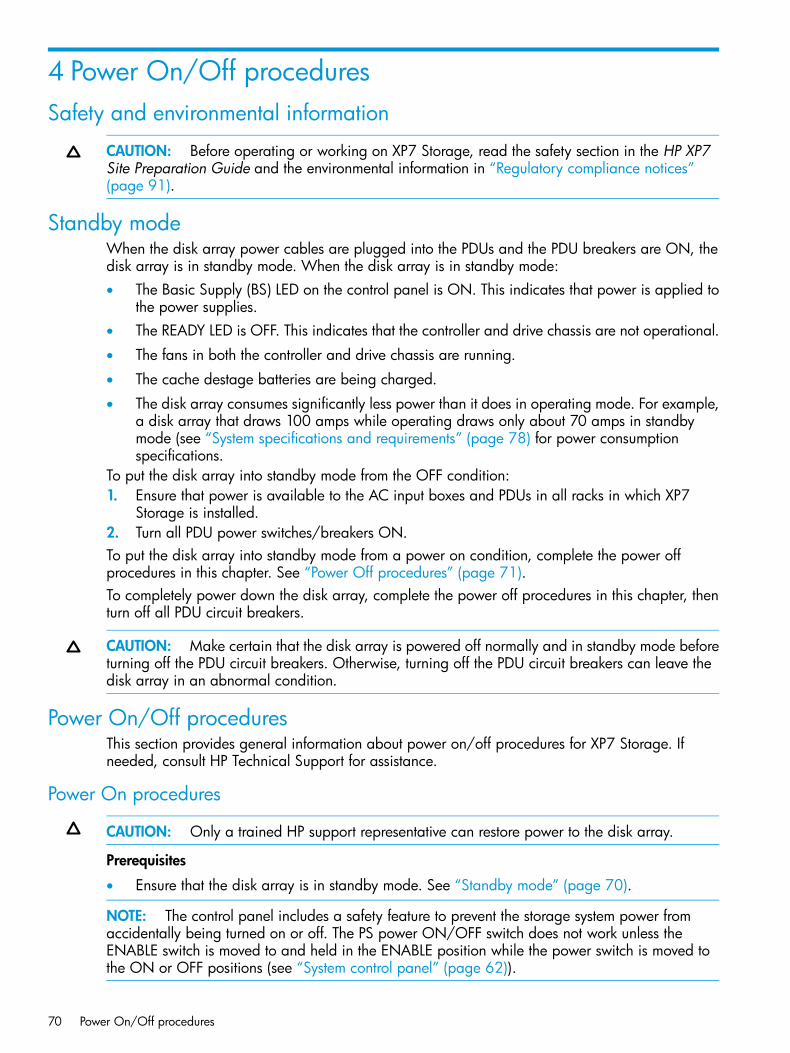
4 Power On/Off proceduresSafety and environmental information
CAUTION: Before operating or working on XP7 Storage, read the safety section in the HP XP7Site Preparation Guide and the environmental information in “Regulatory compliance notices”(page 91).
Standby modeWhen the disk array power cables are plugged into the PDUs and the PDU breakers are ON, thedisk array is in standby mode. When the disk array is in standby mode:• The Basic Supply (BS) LED on the control panel is ON. This indicates that power is applied to
the power supplies.• The READY LED is OFF. This indicates that the controller and drive chassis are not operational.
• The fans in both the controller and drive chassis are running.
• The cache destage batteries are being charged.
• The disk array consumes significantly less power than it does in operating mode. For example,a disk array that draws 100 amps while operating draws only about 70 amps in standbymode (see “System specifications and requirements” (page 78) for power consumptionspecifications.
To put the disk array into standby mode from the OFF condition:1. Ensure that power is available to the AC input boxes and PDUs in all racks in which XP7
Storage is installed.2. Turn all PDU power switches/breakers ON.To put the disk array into standby mode from a power on condition, complete the power offprocedures in this chapter. See “Power Off procedures” (page 71).To completely power down the disk array, complete the power off procedures in this chapter, thenturn off all PDU circuit breakers.
CAUTION: Make certain that the disk array is powered off normally and in standby mode beforeturning off the PDU circuit breakers. Otherwise, turning off the PDU circuit breakers can leave thedisk array in an abnormal condition.
Power On/Off proceduresThis section provides general information about power on/off procedures for XP7 Storage. Ifneeded, consult HP Technical Support for assistance.
Power On procedures
CAUTION: Only a trained HP support representative can restore power to the disk array.
Prerequisites
• Ensure that the disk array is in standby mode. See “Standby mode” (page 70).
NOTE: The control panel includes a safety feature to prevent the storage system power fromaccidentally being turned on or off. The PS power ON/OFF switch does not work unless theENABLE switch is moved to and held in the ENABLE position while the power switch is moved tothe ON or OFF positions (see “System control panel” (page 62)).
70 Power On/Off procedures
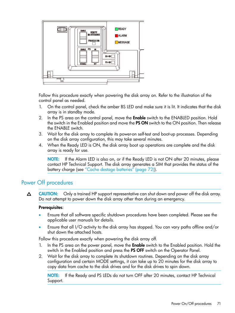
Follow this procedure exactly when powering the disk array on. Refer to the illustration of thecontrol panel as needed.1. On the control panel, check the amber BS LED and make sure it is lit. It indicates that the disk
array is in standby mode.2. In the PS area on the control panel, move the Enable switch to the ENABLED position. Hold
the switch in the Enabled position and move the PS ON switch to the ON position. Then releasethe ENABLE switch.
3. Wait for the disk array to complete its power-on self-test and boot-up processes. Dependingon the disk array configuration, this may take several minutes.
4. When the Ready LED is ON, the disk array boot up operations are complete and the diskarray is ready for use.
NOTE: If the Alarm LED is also on, or if the Ready LED is not ON after 20 minutes, pleasecontact HP Technical Support. The disk array generates a SIM that provides the status of thebattery charge (see “Cache destage batteries” (page 72)).
Power Off procedures
CAUTION: Only a trained HP support representative can shut down and power off the disk array.Do not attempt to power down the disk array other than during an emergency.
Prerequisites:
• Ensure that all software specific shutdown procedures have been completed. Please see theapplicable user manuals for details.
• Ensure that all I/O activity to the disk array has stopped. You can vary paths offline and/orshut down the attached hosts.
Follow this procedure exactly when powering the disk array off.1. In the PS area on the power panel, move the Enable switch to the Enabled position. Hold the
switch in the Enabled position and press the PS OFF switch on the Operator Panel.2. Wait for the disk array to complete its shutdown routines. Depending on the disk array
configuration and certain MODE settings, it can take up to 20 minutes for the disk array tocopy data from cache to the disk drives and for the disk drives to spin down.
NOTE: If the Ready and PS LEDs do not turn OFF after 20 minutes, contact HP TechnicalSupport.
Power On/Off procedures 71
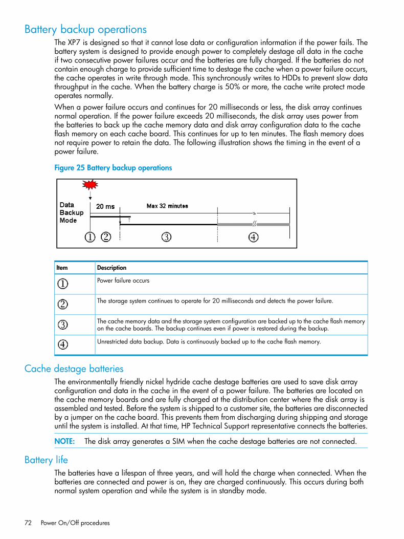
Battery backup operationsThe XP7 is designed so that it cannot lose data or configuration information if the power fails. Thebattery system is designed to provide enough power to completely destage all data in the cacheif two consecutive power failures occur and the batteries are fully charged. If the batteries do notcontain enough charge to provide sufficient time to destage the cache when a power failure occurs,the cache operates in write through mode. This synchronously writes to HDDs to prevent slow datathroughput in the cache. When the battery charge is 50% or more, the cache write protect modeoperates normally.When a power failure occurs and continues for 20 milliseconds or less, the disk array continuesnormal operation. If the power failure exceeds 20 milliseconds, the disk array uses power fromthe batteries to back up the cache memory data and disk array configuration data to the cacheflash memory on each cache board. This continues for up to ten minutes. The flash memory doesnot require power to retain the data. The following illustration shows the timing in the event of apower failure.
Figure 25 Battery backup operations
DescriptionItem
Power failure occurs
The storage system continues to operate for 20 milliseconds and detects the power failure.
The cache memory data and the storage system configuration are backed up to the cache flash memoryon the cache boards. The backup continues even if power is restored during the backup.
Unrestricted data backup. Data is continuously backed up to the cache flash memory.
Cache destage batteriesThe environmentally friendly nickel hydride cache destage batteries are used to save disk arrayconfiguration and data in the cache in the event of a power failure. The batteries are located onthe cache memory boards and are fully charged at the distribution center where the disk array isassembled and tested. Before the system is shipped to a customer site, the batteries are disconnectedby a jumper on the cache board. This prevents them from discharging during shipping and storageuntil the system is installed. At that time, HP Technical Support representative connects the batteries.
NOTE: The disk array generates a SIM when the cache destage batteries are not connected.
Battery lifeThe batteries have a lifespan of three years, and will hold the charge when connected. When thebatteries are connected and power is on, they are charged continuously. This occurs during bothnormal system operation and while the system is in standby mode.
72 Power On/Off procedures
When the batteries are connected and the power is off, the batteries slowly discharge. They willhave a charge of less than 50% after two weeks without power. When fully discharged, the batteriesmust be connected to power for three hours to fully recharge.
NOTE: The disk array generates a SIM when the cache destage batteries are not charged to atleast 50%. The LEDs on the front panel of the cache boards also show the status of the batteries.
Long term array storageWhile connected, the cache destage batteries will completely discharge in two to three weekswithout power applied. If you do not use a XP7 for two weeks or more, contact HP TechnicalSupport to move the batteries to a disk array that is being used, or turn the disk array on to standbymode for at least 3 hours once every two weeks.If you store the system for more than two weeks and do not disconnect the cache destage batteries,when you restart the system, the batteries will need to charge for at least 90 minutes before thecache will be protected. To prevent the batteries from discharging during long term storage, contactHP Technical Support and ask them to disconnect the battery jumpers on the cache boards.
Battery backup operations 73
5 TroubleshootingSolving problems
XP7 Storage is highly reliable and is not expected to fail in any way that would prevent access touser data. The READY LED on the control panel must be ON when the disk array is operatingonline.The following table lists possible error conditions and provides recommended actions for resolvingeach condition. If you are unable to resolve an error condition, contact your HP representative, orcall the support center for assistance.
Table 19 Troubleshooting
Recommended ActionError Condition
Determine the type of error (see the SIM codes section. If possible, remove the cause ofthe error. If you cannot correct the error condition, call the support center for assistance.
Error message displayed.
Turn off all PDU switches and breakers. After the facility power comes back on steady,turn them back on and power the system up. See Chapter 4 for instructions. If needed,call HP support for assistance.
General power failure
Determine if there is a failed storage path. If so, toggle the RESTART switch, and retrythe operation. If the fence message is displayed again, call the support center forassistance.
Fence message is displayedon the console.
Call the support center for assistance. WARNING: Do not open the XP7 controlframe/controller or touch any of the controls.
READY LED does not go on,or there is no powersupplied.
If there is a temperature problem in the area, power down the disk array, lower the roomtemperature to the specified operating range, and power on the storage system. Call
ALARM LED is on.
the support center if needed for assistance with power off/on operations. If the areatemperature is not the cause of the alarm, call the support center for assistance.
Service information messagesXP7 Storage generates SIMs to identify normal operations. For example, Continuous AccessSynchronous pair status change as well as service requirements and errors or failures. For assistancewith SIMs, please call the support center.SIMs can be generated by the channel adapters and disk adapters and by the SVP. All SIMsgenerated by the XP7 are stored on the SVP for use by HP personnel, logged in the SYS1.LOGRECdataset of the mainframe host system, displayed by the Remote Web Console software, andreported over SNMP to the open system host. The SIM display on Remote Web Console enablesusers to remotely view the SIMs reported by the attached disk array. Each time a SIM is generated,the amber Message LED on the control panel turns on. The C-Track remote maintenance tool alsoreports all SIMs to the support centerSIMs are classified according to severity. There are four levels: service, moderate, serious, or acute.The service and moderate SIMs (lowest severity) do not require immediate attention and areaddressed during routine maintenance. The serious and acute SIMs (highest severity) are reportedto the mainframe host (s) once every eight hours.
NOTE: If a serious or acute level SIM is reported, call the support center immediately to ensurethat the problem is being addressed.
The following figure illustrates a typical 32 byte SIM from XP7 Storage. SIMs are displayed byreference code (RC) and severity. The six digit RC, which is composed of bytes 22, 23, and 13,identifies the possible error and determines the severity. The SIM type, located in byte 28, indicateswhich component experienced the error.
74 Troubleshooting
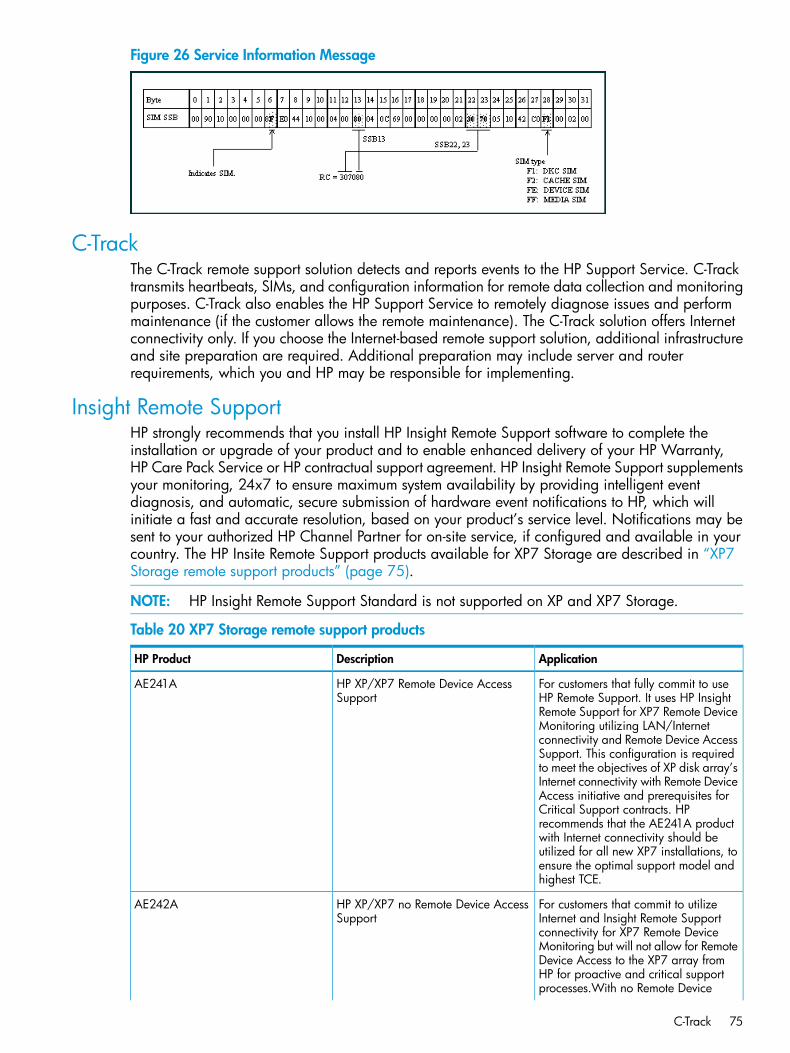
Figure 26 Service Information Message
C-TrackThe C-Track remote support solution detects and reports events to the HP Support Service. C-Tracktransmits heartbeats, SIMs, and configuration information for remote data collection and monitoringpurposes. C-Track also enables the HP Support Service to remotely diagnose issues and performmaintenance (if the customer allows the remote maintenance). The C-Track solution offers Internetconnectivity only. If you choose the Internet-based remote support solution, additional infrastructureand site preparation are required. Additional preparation may include server and routerrequirements, which you and HP may be responsible for implementing.
Insight Remote SupportHP strongly recommends that you install HP Insight Remote Support software to complete theinstallation or upgrade of your product and to enable enhanced delivery of your HP Warranty,HP Care Pack Service or HP contractual support agreement. HP Insight Remote Support supplementsyour monitoring, 24x7 to ensure maximum system availability by providing intelligent eventdiagnosis, and automatic, secure submission of hardware event notifications to HP, which willinitiate a fast and accurate resolution, based on your product’s service level. Notifications may besent to your authorized HP Channel Partner for on-site service, if configured and available in yourcountry. The HP Insite Remote Support products available for XP7 Storage are described in “XP7Storage remote support products” (page 75).
NOTE: HP Insight Remote Support Standard is not supported on XP and XP7 Storage.
Table 20 XP7 Storage remote support products
ApplicationDescriptionHP Product
For customers that fully commit to useHP Remote Support. It uses HP Insight
HP XP/XP7 Remote Device AccessSupport
AE241A
Remote Support for XP7 Remote DeviceMonitoring utilizing LAN/Internetconnectivity and Remote Device AccessSupport. This configuration is requiredto meet the objectives of XP disk array’sInternet connectivity with Remote DeviceAccess initiative and prerequisites forCritical Support contracts. HPrecommends that the AE241A productwith Internet connectivity should beutilized for all new XP7 installations, toensure the optimal support model andhighest TCE.
For customers that commit to utilizeInternet and Insight Remote Support
HP XP/XP7 no Remote Device AccessSupport
AE242A
connectivity for XP7 Remote DeviceMonitoring but will not allow for RemoteDevice Access to the XP7 array fromHP for proactive and critical supportprocesses.With no Remote Device
C-Track 75
Table 20 XP7 Storage remote support products (continued)
ApplicationDescriptionHP Product
Access, Critical Support contractprerequisites cannot be met.
For a customer whose strict securityprotocols specifically prohibit inbound/
HP XP/XP7 Mission Critical No LANSupport
AE244A
outbound traffic to/from the data centerand thus will not allow Remote Supportconnection by either modem orLAN/internet connectivity; but doeshave Mission Critical Services withCustomer Engineer onsite included inthe terms of the support contract.Factory Authorization will be requiredto order this product. Proof of validCustomer Engineer onsite MissionCritical support contract must beprovided for Factory Authorizationapproval.
For a customer whose strict securityprotocols specifically prohibit
HP XP/XP7 No Mission Critical LANSupport
AE245A
inbound/outbound traffic to/from thedata center and thus will not allowRemote Support connection by eithermodem or LAN and does not have aMission Critical Services on-sitecontract. The added cost of thisconfiguration only covers the additionalwarranty support cost to HP duringwarranty period. Other additional costscan also be incurred for supportcontracts for customers who do not haveremote support configured.
Details are available at:http://www.hp.com/go/insightremotesupportTo download the software, go to Software Depot:http://www.software.hp.comSelect Insight Remote Support from the menu on the right.
Failure detection and reporting processIf a failure occurs in the system, the failure is detected and reported to the system log, the SIM log,and HP technical support, as shown in “Failure reporting process” (page 77).
76 Troubleshooting
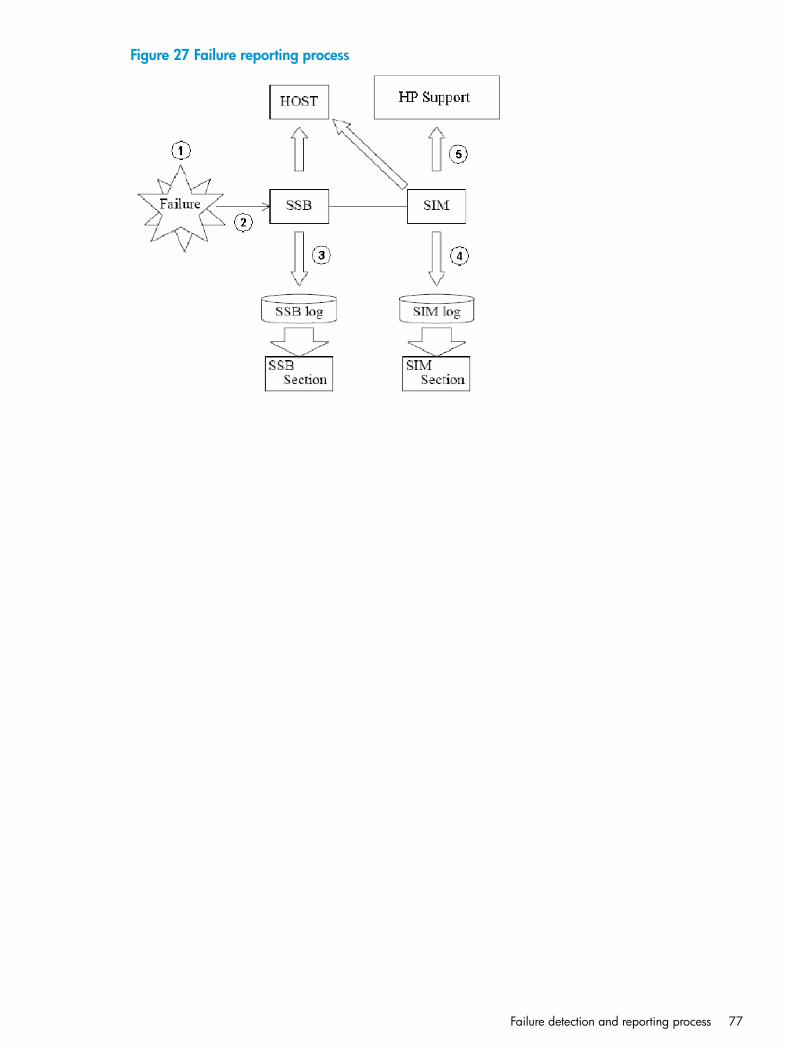
Figure 27 Failure reporting process
Failure detection and reporting process 77
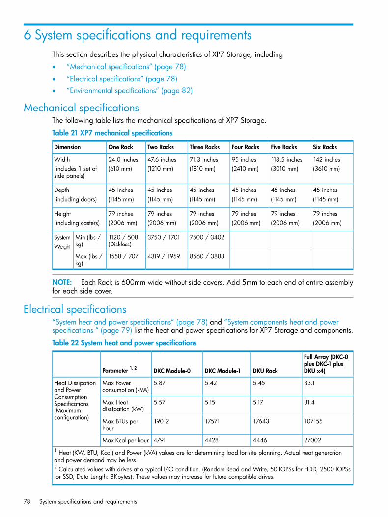
6 System specifications and requirementsThis section describes the physical characteristics of XP7 Storage, including
• “Mechanical specifications” (page 78)
• “Electrical specifications” (page 78)
• “Environmental specifications” (page 82)
Mechanical specificationsThe following table lists the mechanical specifications of XP7 Storage.
Table 21 XP7 mechanical specifications
Six RacksFive RacksFour RacksThree RacksTwo RacksOne RackDimension
142 inches118.5 inches95 inches71.3 inches47.6 inches24.0 inchesWidth(3610 mm)(3010 mm)(2410 mm)(1810 mm)(1210 mm)(610 mm)(includes 1 set of
side panels)
45 inches45 inches45 inches45 inches45 inches45 inchesDepth(1145 mm)(1145 mm)(1145 mm)(1145 mm)(1145 mm)(1145 mm)(including doors)
79 inches79 inches79 inches79 inches79 inches79 inchesHeight(2006 mm)(2006 mm)(2006 mm)(2006 mm)(2006 mm)(2006 mm)(including casters)
7500 / 34023750 / 17011120 / 508(Diskless)
Min (lbs /kg)
SystemWeight
8560 / 38834319 / 19591558 / 707Max (lbs /kg)
NOTE: Each Rack is 600mm wide without side covers. Add 5mm to each end of entire assemblyfor each side cover.
Electrical specifications“System heat and power specifications” (page 78) and “System components heat and powerspecifications ” (page 79) list the heat and power specifications for XP7 Storage and components.
Table 22 System heat and power specifications
Full Array (DKC-0plus DKC-1 plusDKU x4)DKU RackDKC Module-1DKC Module-0Parameter 1, 2
33.15.455.425.87Max Powerconsumption (kVA)
Heat Dissipationand PowerConsumption
31.45.175.155.57Max Heatdissipation (kW)
Specifications(Maximumconfiguration)
107155176431757119012Max BTUs perhour
27002444644284791Max Kcal per hour1 Heat (KW, BTU, Kcal) and Power (kVA) values are for determining load for site planning. Actual heat generationand power demand may be less.2 Calculated values with drives at a typical I/O condition. (Random Read and Write, 50 IOPSs for HDD, 2500 IOPSsfor SSD, Data Length: 8Kbytes). These values may increase for future compatible drives.
78 System specifications and requirements
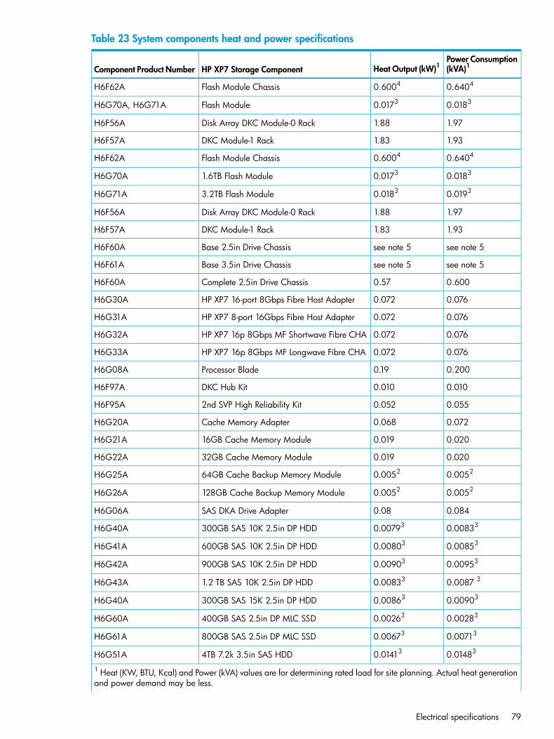
Table 23 System components heat and power specifications
Power Consumption(kVA)1Heat Output (kW)1HP XP7 Storage ComponentComponent Product Number
0.64040.6004Flash Module ChassisH6F62A
0.01830.0173Flash ModuleH6G70A, H6G71A
1.971.88Disk Array DKC Module-0 RackH6F56A
1.931.83DKC Module-1 RackH6F57A
0.64040.6004Flash Module ChassisH6F62A
0.01830.01731.6TB Flash ModuleH6G70A
0.01930.01833.2TB Flash ModuleH6G71A
1.971.88Disk Array DKC Module-0 RackH6F56A
1.931.83DKC Module-1 RackH6F57A
see note 5see note 5Base 2.5in Drive ChassisH6F60A
see note 5see note 5Base 3.5in Drive ChassisH6F61A
0.6000.57Complete 2.5in Drive ChassisH6F60A
0.0760.072HP XP7 16-port 8Gbps Fibre Host AdapterH6G30A
0.0760.072HP XP7 8-port 16Gbps Fibre Host AdapterH6G31A
0.0760.072HP XP7 16p 8Gbps MF Shortwave Fibre CHAH6G32A
0.0760.072HP XP7 16p 8Gbps MF Longwave Fibre CHAH6G33A
0.2000.19Processor BladeH6G08A
0.0100.010DKC Hub KitH6F97A
0.0550.0522nd SVP High Reliability KitH6F95A
0.0720.068Cache Memory AdapterH6G20A
0.0200.01916GB Cache Memory ModuleH6G21A
0.0200.01932GB Cache Memory ModuleH6G22A
0.00520.005264GB Cache Backup Memory ModuleH6G25A
0.00520.0052128GB Cache Backup Memory ModuleH6G26A
0.0840.08SAS DKA Drive AdapterH6G06A
0.008330.00793300GB SAS 10K 2.5in DP HDDH6G40A
0.008530.00803600GB SAS 10K 2.5in DP HDDH6G41A
0.009530.00903900GB SAS 10K 2.5in DP HDDH6G42A
0.0087 30.008331.2 TB SAS 10K 2.5in DP HDDH6G43A
0.009030.00863300GB SAS 15K 2.5in DP HDDH6G40A
0.002830.00263400GB SAS 2.5in DP MLC SSDH6G60A
0.007130.00673800GB SAS 2.5in DP MLC SSDH6G61A
0.014830.014134TB 7.2k 3.5in SAS HDDH6G51A
1 Heat (KW, BTU, Kcal) and Power (kVA) values are for determining rated load for site planning. Actual heat generationand power demand may be less.
Electrical specifications 79
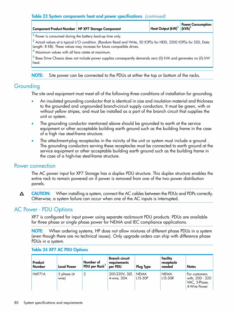
Table 23 System components heat and power specifications (continued)
Power Consumption(kVA)1Heat Output (kW)1HP XP7 Storage ComponentComponent Product Number
2 Power is consumed during the battery back-up time only.3 Actual values at a typical I/O condition. (Random Read and Write, 50 IOPSs for HDD, 2500 IOPSs for SSD, DataLength: 8 KB). These values may increase for future compatible drives.4 Maximum values with all fans rotate at maximum.5 Base Drive Chassis does not include power supplies consequently demands zero (0) kVA and generates no (0) kWheat.
NOTE: Site power can be connected to the PDUs at either the top or bottom of the racks.
GroundingThe site and equipment must meet all of the following three conditions of installation for grounding.
• An insulated grounding conductor that is identical in size and insulation material and thicknessto the grounded and ungrounded branch-circuit supply conductors. It must be green, with orwithout yellow stripes, and must be installed as a part of the branch circuit that supplies theunit or system.
• The grounding conductor mentioned above should be grounded to earth at the serviceequipment or other acceptable building earth ground such as the building frame in the caseof a high rise steel-frame structure.
• The attachment-plug receptacles in the vicinity of the unit or system must include a ground .The grounding conductors serving these receptacles must be connected to earth ground at theservice equipment or other acceptable building earth ground such as the building frame inthe case of a high-rise steel-frame structure.
Power connectionThe AC power input for XP7 Storage has a duplex PDU structure. This duplex structure enables theentire rack to remain powered on if power is removed from one of the two power distributionpanels.
CAUTION: When installing a system, connect the AC cables between the PDUs and PDPs correctly.Otherwise, a system failure can occur when one of the AC inputs is interrupted.
AC Power - PDU OptionsXP7 is configured for input power using separate rackmount PDU products. PDUs are availablefor three phase or single phase power for NEMA and IEC compliance applications.
NOTE: When ordering systems, HP does not allow mixtures of different phase PDUs in a system(even though there are no technical issues). Only upgrade orders can ship with difference phasePDUs in a system.
Table 24 XP7 AC PDU Options
Notes
FacilityreceptacleneededPlug Type
Branch circuitrequirementsper PDU
Number ofPDU per Rack1Local Power
ProductNumber
For customerswith, 200 - 220
NEMAL15-30R
NEMAL15-30P
200-220V, 3Ø,4-wire, 30A
23 phase (4wire)
H6F71A
VAC, 3-Phase,4-Wire Power
80 System specifications and requirements
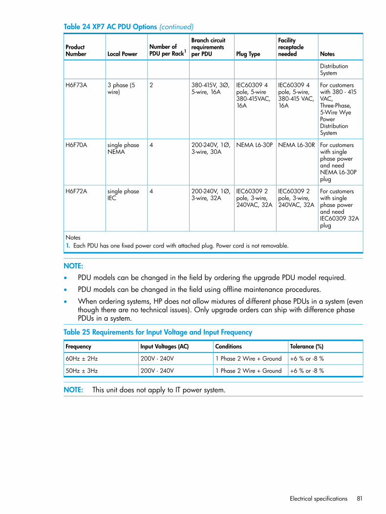
Table 24 XP7 AC PDU Options (continued)
Notes
FacilityreceptacleneededPlug Type
Branch circuitrequirementsper PDU
Number ofPDU per Rack1Local Power
ProductNumber
DistributionSystem
For customerswith 380 - 415
IEC60309 4pole, 5-wire,
IEC60309 4pole, 5-wire
380-415V, 3Ø,5-wire, 16A
23 phase (5wire)
H6F73A
VAC,380-415 VAC,16A
380-415VAC,16A Three-Phase,
5-Wire WyePowerDistributionSystem
For customerswith single
NEMA L6-30RNEMA L6-30P200-240V, 1Ø,3-wire, 30A
4single phaseNEMA
H6F70A
phase powerand needNEMA L6-30Pplug
For customerswith single
IEC60309 2pole, 3-wire,240VAC, 32A
IEC60309 2pole, 3-wire,240VAC, 32A
200-240V, 1Ø,3-wire, 32A
4single phaseIEC
H6F72A
phase powerand needIEC60309 32Aplug
Notes1. Each PDU has one fixed power cord with attached plug. Power cord is not removable.
NOTE:• PDU models can be changed in the field by ordering the upgrade PDU model required.
• PDU models can be changed in the field using offline maintenance procedures.
• When ordering systems, HP does not allow mixtures of different phase PDUs in a system (eventhough there are no technical issues). Only upgrade orders can ship with difference phasePDUs in a system.
Table 25 Requirements for Input Voltage and Input Frequency
Tolerance (%)ConditionsInput Voltages (AC)Frequency
+6 % or -8 %1 Phase 2 Wire + Ground200V - 240V60Hz ± 2Hz
+6 % or -8 %1 Phase 2 Wire + Ground200V - 240V50Hz ± 3Hz
NOTE: This unit does not apply to IT power system.
Electrical specifications 81
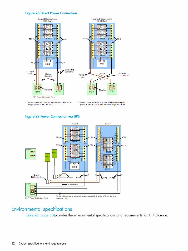
Figure 28 Direct Power Connection
Figure 29 Power Connection via UPS
Environmental specificationsTable 26 (page 83)provides the environmental specifications and requirements for XP7 Storage.
82 System specifications and requirements

Table 26 XP7 Environmental specifications
In StorageNot OperatingOperatingItem
-25 to 60-10 to 4360.8 - 80.9 /Temperature ºC-10 to 35816 to 32
5 to 958 to 9020 to 80Relative Humidity (%)2
292726Max. Wet Bulb ºC
201010Temperature Deviation ºCper hour)
Sine Vibration: 4.9 m/s1, 5 min.5 to 10 Hz: 2.5 mm10 to 70 Hz: 4.9 m/s1
5 to 10Hz: 0.25 mm10 to 300Hz:0.49m/s2
Vibration to 10Hz: 0.25mm At the resonant frequency with
the highest displacement foundbetween 3 to 100 Hz 370 to 99 Hz: 0.05 mm
99 to 300 Hz: 9.8 m/s1
Random Vibration:0.147 m2/s330 min, 5 to 100 Hz 4
--Up to 2.5 7Earthquakeresistance (m/s2)
Horizontal:78.4 m/s1, 15 ms-ShockIncline Impact 1.22 m/s5
Vertical:Rotational Edge 0.15 m6
--60 m to 3,000 mAltitude
Notes1. The requirements for operating condition should be satisfied before the storage system is powered on. Maximum
temperature of 32°C should be strictly satisfied at air inlet portion. The recommended operational room temperatureis 21°C to 24°C.
2. Non-operating condition includes both packing and unpacking conditions unless otherwise specified.3. For shipping and storage, the product should be packed with factory packing.4. No condensation in and around the drives/media should be observed under any conditions.5. The vibration specifications apply to all three axes.6. See ASTM D999-01 The Methods for Vibration Testing of Shipping Containers.7. See ASTM D4728-01 Test Method for Random Vibration Testing of Shipping Containers.8. See ASTM D5277-92 Test Method for Performing Programmed Horizontal Impacts Using an Inclined Impact Tester.9. See ASTM D6055-96 Test Methods for Mechanical Handling of Unitized Loads and Large Shipping Cases and
Crates.10.When FMDs are installed.
Heat output and air flowThe following table lists the heat output and air flow requirements for XP7 Storage.Both the control chassis and the disk chassis contain front and rear fans to circulate air throughthe chassis from front to back. Air flows in through the front bezel to the rear of the componentand exits through the perforations in the rear door. Either the front fans or the rear fans can coolthe chassis by themselves. The racks do not contain fans. Airflow is from front to back.
Heat output and air flow 83
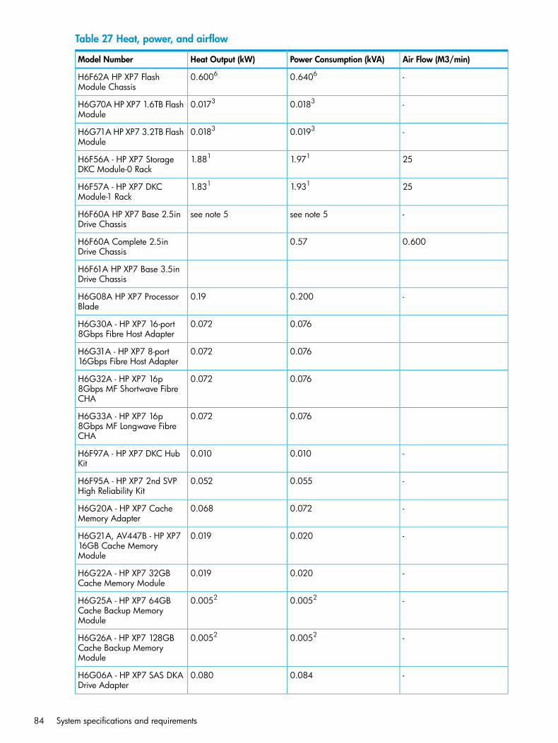
Table 27 Heat, power, and airflow
Air Flow (M3/min)Power Consumption (kVA)Heat Output (kW)Model Number
-0.64060.6006H6F62A HP XP7 FlashModule Chassis
-0.01830.0173H6G70A HP XP7 1.6TB FlashModule
-0.01930.0183H6G71A HP XP7 3.2TB FlashModule
251.9711.881H6F56A - HP XP7 StorageDKC Module-0 Rack
251.9311.831H6F57A - HP XP7 DKCModule-1 Rack
-see note 5see note 5H6F60A HP XP7 Base 2.5inDrive Chassis
0.6000.57H6F60A Complete 2.5inDrive Chassis
H6F61A HP XP7 Base 3.5inDrive Chassis
-0.2000.19H6G08A HP XP7 ProcessorBlade
0.0760.072H6G30A - HP XP7 16-port8Gbps Fibre Host Adapter
0.0760.072H6G31A - HP XP7 8-port16Gbps Fibre Host Adapter
0.0760.072H6G32A - HP XP7 16p8Gbps MF Shortwave FibreCHA
0.0760.072H6G33A - HP XP7 16p8Gbps MF Longwave FibreCHA
-0.0100.010H6F97A - HP XP7 DKC HubKit
-0.0550.052H6F95A - HP XP7 2nd SVPHigh Reliability Kit
-0.0720.068H6G20A - HP XP7 CacheMemory Adapter
-0.0200.019H6G21A, AV447B - HP XP716GB Cache MemoryModule
-0.0200.019H6G22A - HP XP7 32GBCache Memory Module
-0.00520.0052H6G25A - HP XP7 64GBCache Backup MemoryModule
-0.00520.0052H6G26A - HP XP7 128GBCache Backup MemoryModule
-0.0840.080H6G06A - HP XP7 SAS DKADrive Adapter
84 System specifications and requirements
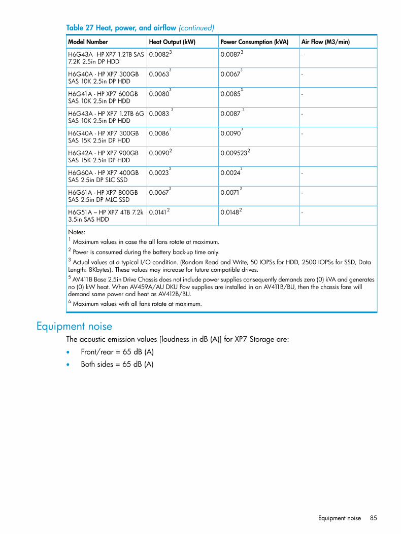
Table 27 Heat, power, and airflow (continued)
Air Flow (M3/min)Power Consumption (kVA)Heat Output (kW)Model Number
-0.008730.00823H6G43A - HP XP7 1.2TB SAS7.2K 2.5in DP HDD
-0.00673
0.00633
H6G40A - HP XP7 300GBSAS 10K 2.5in DP HDD
-0.00853
0.00803
H6G41A - HP XP7 600GBSAS 10K 2.5in DP HDD
-0.00873
0.00833
H6G43A - HP XP7 1.2TB 6GSAS 10K 2.5in DP HDD
-0.00903
0.00863
H6G40A - HP XP7 300GBSAS 15K 2.5in DP HDD
0.00952320.00902H6G42A - HP XP7 900GBSAS 15K 2.5in DP HDD
-0.00243
0.00233
H6G60A - HP XP7 400GBSAS 2.5in DP SLC SSD
-0.00713
0.00673
H6G61A - HP XP7 800GBSAS 2.5in DP MLC SSD
-0.014820.01412H6G51A – HP XP7 4TB 7.2k3.5in SAS HDD
Notes:1 Maximum values in case the all fans rotate at maximum.2 Power is consumed during the battery back-up time only.3 Actual values at a typical I/O condition. (Random Read and Write, 50 IOPSs for HDD, 2500 IOPSs for SSD, DataLength: 8Kbytes). These values may increase for future compatible drives.5 AV411B Base 2.5in Drive Chassis does not include power supplies consequently demands zero (0) kVA and generatesno (0) kW heat. When AV459A/AU DKU Pow supplies are installed in an AV411B/BU, then the chassis fans willdemand same power and heat as AV412B/BU.6 Maximum values with all fans rotate at maximum.
Equipment noiseThe acoustic emission values [loudness in dB (A)] for XP7 Storage are:
• Front/rear = 65 dB (A)
• Both sides = 65 dB (A)
Equipment noise 85
7 Support and other resourcesContacting HP
For worldwide technical support information, see the HP support website:http://www.hp.com/support
Before contacting HP, collect the following information:
• Product model names and numbers
• Technical support registration number (if applicable)
• Product serial numbers
• Error messages
• Operating system type and revision level
• Detailed questions
Subscription serviceReceive, by email, support alerts announcing product support communications, driver updates,software releases, firmware updates, and customer-replaceable component information by signingup at http://www.hp.com/go/myadvisory.To change options for support alerts you already receive, click the Sign in link on the right.
Documentation feedbackHP welcomes your feedback.To make comments and suggestions about product documentation, please send a message [email protected]. Include the document title and manufacturing part number. All submissionsbecome the property of HP.
Related informationThe following documents provide related information:
• HP XP7 Disk Array Owner's Guide
• HP XP7 LUN Manager User's Guide
• HP XP7 Provisioning for Open Systems User Guide
• HP XP7 Remote Web Console User Guide
• HP XP7 Command View Advanced Edition Software Device Manager User Guide
• HP XP7 Mainframe Host Attachment and Operations GuideYou can find these documents on the HP Manuals website:
http://www.hp.com/support/manuals
In the Storage section, click Disk Storage Systems and then select a product.
Conventions for storage capacity valuesHP XP7 storage systems use the following values to calculate physical storage capacity values(hard disk drives):
• 1 KB (kilobyte) = 1,000 (103) bytes
• 1 MB (megabyte) = 1,0002 bytes
86 Support and other resources
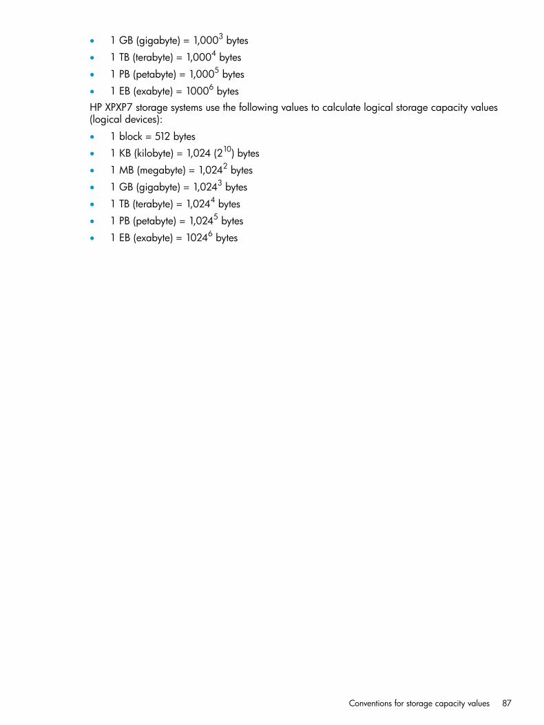
• 1 GB (gigabyte) = 1,0003 bytes
• 1 TB (terabyte) = 1,0004 bytes
• 1 PB (petabyte) = 1,0005 bytes
• 1 EB (exabyte) = 10006 bytesHP XPXP7 storage systems use the following values to calculate logical storage capacity values(logical devices):
• 1 block = 512 bytes
• 1 KB (kilobyte) = 1,024 (210) bytes
• 1 MB (megabyte) = 1,0242 bytes
• 1 GB (gigabyte) = 1,0243 bytes
• 1 TB (terabyte) = 1,0244 bytes
• 1 PB (petabyte) = 1,0245 bytes
• 1 EB (exabyte) = 10246 bytes
Conventions for storage capacity values 87
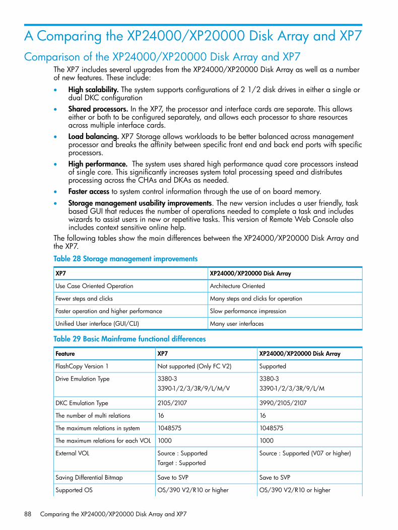
A Comparing the XP24000/XP20000 Disk Array and XP7Comparison of the XP24000/XP20000 Disk Array and XP7
The XP7 includes several upgrades from the XP24000/XP20000 Disk Array as well as a numberof new features. These include:• High scalability. The system supports configurations of 2 1/2 disk drives in either a single or
dual DKC configuration• Shared processors. In the XP7, the processor and interface cards are separate. This allows
either or both to be configured separately, and allows each processor to share resourcesacross multiple interface cards.
• Load balancing. XP7 Storage allows workloads to be better balanced across managementprocessor and breaks the affinity between specific front end and back end ports with specificprocessors.
• High performance. The system uses shared high performance quad core processors insteadof single core. This significantly increases system total processing speed and distributesprocessing across the CHAs and DKAs as needed.
• Faster access to system control information through the use of on board memory.• Storage management usability improvements. The new version includes a user friendly, task
based GUI that reduces the number of operations needed to complete a task and includeswizards to assist users in new or repetitive tasks. This version of Remote Web Console alsoincludes context sensitive online help.
The following tables show the main differences between the XP24000/XP20000 Disk Array andthe XP7.
Table 28 Storage management improvements
XP24000/XP20000 Disk ArrayXP7
Architecture OrientedUse Case Oriented Operation
Many steps and clicks for operationFewer steps and clicks
Slow performance impressionFaster operation and higher performance
Many user interfacesUnified User interface (GUI/CLI)
Table 29 Basic Mainframe functional differences
XP24000/XP20000 Disk ArrayXP7Feature
SupportedNot supported (Only FC V2)FlashCopy Version 1
3380-33380-3Drive Emulation Type3390-1/2/3/3R/9/L/M3390-1/2/3/3R/9/L/M/V
3990/2105/21072105/2107DKC Emulation Type
1616The number of multi relations
10485751048575The maximum relations in system
10001000The maximum relations for each VOL
Source : Supported (V07 or higher)Source : SupportedExternal VOLTarget : Supported
Save to SVPSave to SVPSaving Differential Bitmap
OS/390 V2/R10 or higherOS/390 V2/R10 or higherSupported OS
88 Comparing the XP24000/XP20000 Disk Array and XP7
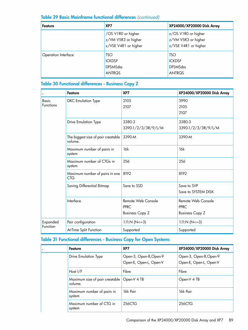
Table 29 Basic Mainframe functional differences (continued)
XP24000/XP20000 Disk ArrayXP7Feature
z/OS V1R0 or higher/OS V1R0 or higherz/VM V5R3 or higherz/VM V5R3 or higherz/VSE V4R1 or higherz/VSE V4R1 or higher
TSOTSOOperation InterfaceICKDSFICKDSFDFSMSdssDFSMSdssANTRQSANTRQS
Table 30 Functional differences - Business Copy Z
XP24000/XP20000 Disk ArrayXP7Feature.
39902105DKC Emulation TypeBasicFunctions 21052107
2107
3380-33380-3Drive Emulation Type3390-1/2/3/3R/9/L/M3390-1/2/3/3R/9/L/M
3390-M3390-MThe biggest size of pair creatablevolume.
16k16kMaximum number of pairs insystem
256256Maximum number of CTGs insystem
81928192Maximum number of pairs in oneCTG
Save to SVPSave to SSDSaving Differential BitmapSave to SYSTEM DISK
Remote Web ConsoleRemote Web ConsoleInterfacePPRCPPRCBusiness Copy ZBusiness Copy Z
1:11:N (N<=3)1:11:N (N<=3)Pair configurationExpandedFunction
SupportedSupportedAt-Time Split Function
Table 31 Functional differences - Business Copy for Open Systems
XP24000/XP20000 Disk ArrayXP7Feature.
Open-3, Open-8,Open-9Open-3, Open-8,Open-9Drive Emulation TypeOpen-E, Open-L, Open-VOpen-E, Open-L, Open-V
FibreFibreHost I/F
Open-V 4 TBOpen-V 4 TBMaximum size of pair creatablevolume.
16k Pair16k PairMaximum number of pairs insystem
256CTG256CTGMaximum number of CTG insystem
Comparison of the XP24000/XP20000 Disk Array and XP7 89
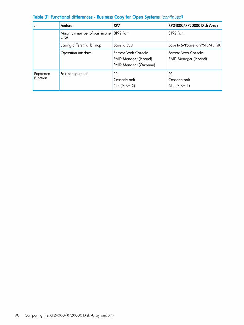
Table 31 Functional differences - Business Copy for Open Systems (continued)
XP24000/XP20000 Disk ArrayXP7Feature.
8192 Pair8192 PairMaximum number of pair in oneCTG
Save to SVPSave to SYSTEM DISKSave to SSDSaving differential bitmap
Remote Web ConsoleRemote Web ConsoleOperation interfaceRAID Manager (Inband)RAID Manager (Inband)
RAID Manager (Outband)
1:11:1Pair configurationExpandedFunction Cascade pairCascade pair
1:N (N <= 3)1:N (N <= 3)
90 Comparing the XP24000/XP20000 Disk Array and XP7

B Regulatory compliance noticesThis section contains regulatory notices for XP7 Storage.
Regulatory compliance identification numbersFor the purpose of regulatory compliance certifications and identification, this product has beenassigned a unique regulatory model number. The regulatory model number can be found on theproduct nameplate label, along with all required approval markings and information. Whenrequesting compliance information for this product, always refer to this regulatory model number.The regulatory model number is not the marketing name or model number of the product.Product specific information:HP XP7 StorageRegulatory model number: CSPRA-0390FCC and CISPR classification: Class AThese products contain laser components. See Class 1 laser statement in the Laser compliancenotices section.
Federal Communications Commission noticePart 15 of the Federal Communications Commission (FCC) Rules and Regulations has establishedRadio Frequency (RF) emission limits to provide an interference-free radio frequency spectrum.Many electronic devices, including computers, generate RF energy incidental to their intendedfunction and are, therefore, covered by these rules. These rules place computers and relatedperipheral devices into two classes, A and B, depending upon their intended installation. Class Adevices are those that may reasonably be expected to be installed in a business or commercialenvironment. Class B devices are those that may reasonably be expected to be installed in aresidential environment (for example, personal computers). The FCC requires devices in both classesto bear a label indicating the interference potential of the device as well as additional operatinginstructions for the user.
FCC rating labelThe FCC rating label on the device shows the classification (A or B) of the equipment. Class Bdevices have an FCC logo or ID on the label. Class A devices do not have an FCC logo or ID onthe label. After you determine the class of the device, refer to the corresponding statement.
Class A equipmentThis equipment has been tested and found to comply with the limits for a Class A digital device,pursuant to Part 15 of the FCC rules. These limits are designed to provide reasonable protectionagainst harmful interference when the equipment is operated in a commercial environment. Thisequipment generates, uses, and can radiate radio frequency energy and, if not installed and usedin accordance with the instructions, may cause harmful interference to radio communications.Operation of this equipment in a residential area is likely to cause harmful interference, in whichcase the user will be required to correct the interference at personal expense.
Class B equipmentThis equipment has been tested and found to comply with the limits for a Class B digital device,pursuant to Part 15 of the FCC Rules. These limits are designed to provide reasonable protectionagainst harmful interference in a residential installation. This equipment generates, uses, and canradiate radio frequency energy and, if not installed and used in accordance with the instructions,may cause harmful interference to radio communications. However, there is no guarantee thatinterference will not occur in a particular installation. If this equipment does cause harmfulinterference to radio or television reception, which can be determined by turning the equipment
Regulatory compliance identification numbers 91

off and on, the user is encouraged to try to correct the interference by one or more of the followingmeasures:• Reorient or relocate the receiving antenna.• Increase the separation between the equipment and receiver.• Connect the equipment into an outlet on a circuit that is different from that to which the receiver
is connected.• Consult the dealer or an experienced radio or television technician for help.
Declaration of Conformity for products marked with the FCC logo, United States onlyThis device complies with Part 15 of the FCC Rules. Operation is subject to the following twoconditions: (1) this device may not cause harmful interference, and (2) this device must accept anyinterference received, including interference that may cause undesired operation.For questions regarding this FCC declaration, contact us by mail or telephone:• Hewlett-Packard Company P.O. Box 692000, Mail Stop 510101 Houston, Texas 77269-2000• Or call 1-281-514-3333
ModificationThe FCC requires the user to be notified that any changes or modifications made to this devicethat are not expressly approved by Hewlett-Packard Company may void the user's authority tooperate the equipment.
CablesWhen provided, connections to this device must be made with shielded cables with metallic RFI/EMIconnector hoods in order to maintain compliance with FCC Rules and Regulations.
Canadian notice (Avis Canadien)
Class A equipmentThis Class A digital apparatus meets all requirements of the Canadian Interference-CausingEquipment Regulations.Cet appareil numérique de la class A respecte toutes les exigences du Règlement sur le matérielbrouilleur du Canada.
Class B equipmentThis Class B digital apparatus meets all requirements of the Canadian Interference-CausingEquipment Regulations.Cet appareil numérique de la class B respecte toutes les exigences du Règlement sur le matérielbrouilleur du Canada.
European Union noticeThis product complies with the following EU directives:• Low Voltage Directive 2006/95/EC• EMC Directive 2004/108/ECCompliance with these directives implies conformity to applicable harmonized European standards(European Norms) which are listed on the EU Declaration of Conformity issued by Hewlett-Packardfor this product or product family.
92 Regulatory compliance notices
This compliance is indicated by the following conformity marking placed on the product:
This marking is valid for non-Telecom products and EUharmonized Telecom products (e.g., Bluetooth).
Certificates can be obtained from http://www.hp.com/go/certificates.Hewlett-Packard GmbH, HQ-TRE, Herrenberger Strasse 140, 71034 Boeblingen, Germany
Japanese notices
Japanese VCCI-A notice
Japanese VCCI-B notice
Japanese VCCI marking
Japanese power cord statement
Korean notices
Class A equipment
Japanese notices 93
Class B equipment
Taiwanese notices
BSMI Class A notice
Taiwan battery recycle statement
Turkish recycling notice
Türkiye Cumhuriyeti: EEE Yönetmeliğine Uygundur
94 Regulatory compliance notices
Laser compliance notices
English laser noticeThis device may contain a laser that is classified as a Class 1 Laser Product in accordance withU.S. FDA regulations and the IEC 60825-1. The product does not emit hazardous laser radiation.
WARNING! Use of controls or adjustments or performance of procedures other than thosespecified herein or in the laser product's installation guide may result in hazardous radiationexposure. To reduce the risk of exposure to hazardous radiation:• Do not try to open the module enclosure. There are no user-serviceable components inside.• Do not operate controls, make adjustments, or perform procedures to the laser device other
than those specified herein.• Allow only HP Authorized Service technicians to repair the unit.
The Center for Devices and Radiological Health (CDRH) of the U.S. Food and Drug Administrationimplemented regulations for laser products on August 2, 1976. These regulations apply to laserproducts manufactured from August 1, 1976. Compliance is mandatory for products marketed inthe United States.
Dutch laser notice
French laser notice
Laser compliance notices 95
German laser notice
Italian laser notice
Japanese laser notice
96 Regulatory compliance notices
Spanish laser notice
Recycling notices
English recycling noticeDisposal of waste equipment by users in private household in the European Union
This symbol means do not dispose of your product with your other household waste. Instead, you shouldprotect human health and the environment by handing over your waste equipment to a designatedcollection point for the recycling of waste electrical and electronic equipment. For more information,please contact your household waste disposal service
Recycling notices 97
Bulgarian recycling noticeИзхвърляне на отпадъчно оборудване от потребители в частни домакинства в Европейскиясъюз
Този символ върху продукта или опаковката му показва, че продуктът не трябва да се изхвърля заеднос другите битови отпадъци. Вместо това, трябва да предпазите човешкото здраве и околната среда,като предадете отпадъчното оборудване в предназначен за събирането му пункт за рециклиране нанеизползваемо електрическо и електронно борудване. За допълнителна информация се свържете сфирмата по чистота, чиито услуги използвате.
Czech recycling noticeLikvidace zařízení v domácnostech v Evropské unii
Tento symbol znamená, že nesmíte tento produkt likvidovat spolu s jiným domovním odpadem. Místotoho byste měli chránit lidské zdraví a životní prostředí tím, že jej předáte na k tomu určené sběrnépracoviště, kde se zabývají recyklací elektrického a elektronického vybavení. Pro více informací kontaktujtespolečnost zabývající se sběrem a svozem domovního odpadu.
Danish recycling noticeBortskaffelse af brugt udstyr hos brugere i private hjem i EU
Dette symbol betyder, at produktet ikke må bortskaffes sammen med andet husholdningsaffald. Du skali stedet den menneskelige sundhed og miljøet ved at afl evere dit brugte udstyr på et dertil beregnetindsamlingssted for af brugt, elektrisk og elektronisk udstyr. Kontakt nærmeste renovationsafdeling foryderligere oplysninger.
Dutch recycling noticeInzameling van afgedankte apparatuur van particuliere huishoudens in de Europese Unie
Dit symbool betekent dat het product niet mag worden gedeponeerd bij het overige huishoudelijke afval.Bescherm de gezondheid en het milieu door afgedankte apparatuur in te leveren bij een hiervoor bestemdinzamelpunt voor recycling van afgedankte elektrische en elektronische apparatuur. Neem voor meerinformatie contact op met uw gemeentereinigingsdienst.
98 Regulatory compliance notices
Estonian recycling noticeÄravisatavate seadmete likvideerimine Euroopa Liidu eramajapidamistes
See märk näitab, et seadet ei tohi visata olmeprügi hulka. Inimeste tervise ja keskkonna säästmise nimeltuleb äravisatav toode tuua elektriliste ja elektrooniliste seadmete käitlemisega egelevasse kogumispunkti.Küsimuste korral pöörduge kohaliku prügikäitlusettevõtte poole.
Finnish recycling noticeKotitalousjätteiden hävittäminen Euroopan unionin alueella
Tämä symboli merkitsee, että laitetta ei saa hävittää muiden kotitalousjätteiden mukana. Sen sijaan sinunon suojattava ihmisten terveyttä ja ympäristöä toimittamalla käytöstä poistettu laite sähkö- taielektroniikkajätteen kierrätyspisteeseen. Lisätietoja saat jätehuoltoyhtiöltä.
French recycling noticeMise au rebut d'équipement par les utilisateurs privés dans l'Union Européenne
Ce symbole indique que vous ne devez pas jeter votre produit avec les ordures ménagères. Il est devotre responsabilité de protéger la santé et l'environnement et de vous débarrasser de votre équipementen le remettant à une déchetterie effectuant le recyclage des équipements électriques et électroniques.Pour de plus amples informations, prenez contact avec votre service d'élimination des ordures ménagères.
German recycling noticeEntsorgung von Altgeräten von Benutzern in privaten Haushalten in der EU
Dieses Symbol besagt, dass dieses Produkt nicht mit dem Haushaltsmüll entsorgt werden darf. ZumSchutze der Gesundheit und der Umwelt sollten Sie stattdessen Ihre Altgeräte zur Entsorgung einer dafürvorgesehenen Recyclingstelle für elektrische und elektronische Geräte übergeben. Weitere Informationenerhalten Sie von Ihrem Entsorgungsunternehmen für Hausmüll.
Recycling notices 99
Greek recycling noticeΑπόρριψη άχρηοτου εξοπλισμού από ιδιώτες χρήστες στην Ευρωπαϊκή Ένωση
Αυτό το σύμβολο σημαίνει ότι δεν πρέπει να απορρίψετε το προϊόν με τα λοιπά οικιακά απορρίμματα.Αντίθετα, πρέπει να προστατέψετε την ανθρώπινη υγεία και το περιβάλλον παραδίδοντας τον άχρηστοεξοπλισμό σας σε εξουσιοδοτημένο σημείο συλλογής για την ανακύκλωση άχρηστου ηλεκτρικού καιηλεκτρονικού εξοπλισμού. Για περισσότερες πληροφορίες, επικοινωνήστε με την υπηρεσία απόρριψηςαπορριμμάτων της περιοχής σας.
Hungarian recycling noticeA hulladék anyagok megsemmisítése az Európai Unió háztartásaiban
Ez a szimbólum azt jelzi, hogy a készüléket nem szabad a háztartási hulladékkal együtt kidobni. Ehelyetta leselejtezett berendezéseknek az elektromos vagy elektronikus hulladék átvételére kijelölt helyen történőbeszolgáltatásával megóvja az emberi egészséget és a környezetet.További információt a helyiköztisztasági vállalattól kaphat.
Italian recycling noticeSmaltimento di apparecchiature usate da parte di utenti privati nell'Unione Europea
Questo simbolo avvisa di non smaltire il prodotto con i normali rifi uti domestici. Rispettare la saluteumana e l'ambiente conferendo l'apparecchiatura dismessa a un centro di raccolta designato per ilriciclo di apparecchiature elettroniche ed elettriche. Per ulteriori informazioni, rivolgersi al servizio perlo smaltimento dei rifi uti domestici.
Latvian recycling noticeEuropos Sąjungos namų ūkio vartotojų įrangos atliekų šalinimas
Šis simbolis nurodo, kad gaminio negalima išmesti kartu su kitomis buitinėmis atliekomis. Kadapsaugotumėte žmonių sveikatą ir aplinką, pasenusią nenaudojamą įrangą turite nuvežti į elektrinių irelektroninių atliekų surinkimo punktą. Daugiau informacijos teiraukitės buitinių atliekų surinkimo tarnybos.
100 Regulatory compliance notices

Lithuanian recycling noticeNolietotu iekārtu iznīcināšanas noteikumi lietotājiem Eiropas Savienības privātajās mājsaimniecībās
Šis simbols norāda, ka ierīci nedrīkst utilizēt kopā ar citiem mājsaimniecības atkritumiem. Jums jārūpējaspar cilvēku veselības un vides aizsardzību, nododot lietoto aprīkojumu otrreizējai pārstrādei īpašā lietotuelektrisko un elektronisko ierīču savākšanas punktā. Lai iegūtu plašāku informāciju, lūdzu, sazinieties arsavu mājsaimniecības atkritumu likvidēšanas dienestu.
Polish recycling noticeUtylizacja zużytego sprzętu przez użytkowników w prywatnych gospodarstwach domowych wkrajach Unii Europejskiej
Ten symbol oznacza, że nie wolno wyrzucać produktu wraz z innymi domowymi odpadkami.Obowiązkiem użytkownika jest ochrona zdrowa ludzkiego i środowiska przez przekazanie zużytegosprzętu do wyznaczonego punktu zajmującego się recyklingiem odpadów powstałych ze sprzętuelektrycznego i elektronicznego. Więcej informacji można uzyskać od lokalnej firmy zajmującej wywozemnieczystości.
Portuguese recycling noticeDescarte de equipamentos usados por utilizadores domésticos na União Europeia
Este símbolo indica que não deve descartar o seu produto juntamente com os outros lixos domiciliares.Ao invés disso, deve proteger a saúde humana e o meio ambiente levando o seu equipamento paradescarte em um ponto de recolha destinado à reciclagem de resíduos de equipamentos eléctricos eelectrónicos. Para obter mais informações, contacte o seu serviço de tratamento de resíduos domésticos.
Romanian recycling noticeCasarea echipamentului uzat de către utilizatorii casnici din Uniunea Europeană
Acest simbol înseamnă să nu se arunce produsul cu alte deşeuri menajere. În schimb, trebuie să protejaţisănătatea umană şi mediul predând echipamentul uzat la un punct de colectare desemnat pentru reciclareaechipamentelor electrice şi electronice uzate. Pentru informaţii suplimentare, vă rugăm să contactaţiserviciul de eliminare a deşeurilor menajere local.
Recycling notices 101
Slovak recycling noticeLikvidácia vyradených zariadení používateľmi v domácnostiach v Európskej únii
Tento symbol znamená, že tento produkt sa nemá likvidovať s ostatným domovým odpadom. Namiestotoho by ste mali chrániť ľudské zdravie a životné prostredie odovzdaním odpadového zariadenia nazbernom mieste, ktoré je určené na recykláciu odpadových elektrických a elektronických zariadení.Ďalšie informácie získate od spoločnosti zaoberajúcej sa likvidáciou domového odpadu.
Spanish recycling noticeEliminación de los equipos que ya no se utilizan en entornos domésticos de la Unión Europea
Este símbolo indica que este producto no debe eliminarse con los residuos domésticos. En lugar de ello,debe evitar causar daños a la salud de las personas y al medio ambiente llevando los equipos que noutilice a un punto de recogida designado para el reciclaje de equipos eléctricos y electrónicos que yano se utilizan. Para obtener más información, póngase en contacto con el servicio de recogida deresiduos domésticos.
Swedish recycling noticeHantering av elektroniskt avfall för hemanvändare inom EU
Den här symbolen innebär att du inte ska kasta din produkt i hushållsavfallet. Värna i stället om naturoch miljö genom att lämna in uttjänt utrustning på anvisad insamlingsplats. Allt elektriskt och elektronisktavfall går sedan vidare till återvinning. Kontakta ditt återvinningsföretag för mer information.
Battery replacement notices
Dutch battery notice
102 Regulatory compliance notices
French battery notice
German battery notice
Battery replacement notices 103
Italian battery notice
Japanese battery notice
104 Regulatory compliance notices
Spanish battery notice
Battery replacement notices 105
Glossaryaccess method An IBM-specific term for software that moves data between main storage and I/O devices to
create channel programs and manage system buffers.BC An HP application that provides volume-level, point-in-time copies in the disk array.BC Z The version of Business Copy that supports mainframe volumes.CLI Command-line interface. An interface comprised of various commands which are used to control
operating system responses.CLPR Cache logical partition.Cnt Ac-J HP XP7 Continuous Access Journal software.Cnt Ac-J Z The version of Continuous Access Journal that supports mainframe volumes.Cnt Ac-S XP7 Continuous Access Synchronous software.Cnt Ac-S Z The version of Continuous Access Synchronous that supports mainframe volumes.command device A volume in the disk array that accepts Continuous Access, Business Copy, or Business Continuity
Manager control operations, which are then executed by the array.CT group Consistency group.CU Control Unit. Used to organize the storage space attached to the disk controller ( DKC). You can
group similarly configured logical devices (LDEVs) with unique control unit images (CUs). CUsare numbered sequentially. The disk array supports a certain number of CUs, depending on thedisk array model. Each CU can manage multiple LDEVs; therefore, both the CU number and theLDEV number are required to identify an LDEV.
CVS CVS devices (OPEN-x CVS or 3390-x CVS) are custom volumes configured using arraymanagement software to be smaller or larger than normal fixed-size OPEN or mainframe systemvolumes. Synonymous with volume size customization (VSC). OPEN-V is a CVS-based volume.
DFSMS Data Facility Storage Management Subsystem.DKA Disk adapter.DKC Disk controller.emulation mode The LDEVs associated with each RAID group are assigned an emulation mode that makes them
operate like OPEN system disk drives. The emulation mode determines the size of an LDEV orvolume.OPEN-V: User-defined custom size3390-3/3R: 2.838 GB3390-9: 8.514 GB3390-L: 27.844 GB3390-M: 55.689 GB3380-3 2.377 GB
Fibre Channel A data transfer architecture designed for mass storage devices and other peripheral devices thatrequire high bandwidth.
HDD Hard disk drive.LDKC Logical disk controller.LUN Logical unit number. A LUN results from mapping a logical unit number, port ID, and LDEV ID to
a RAID group. The size of the LUN is determined by the emulation mode of the LDEV and thenumber of LDEVs associated with the LUN.
LUSE Logical Unit Size Expansion. The LUSE feature is available when the HP XP7 LUN Managerproduct is installed, and allows a LUN, normally associated with only a single LDEV, to beassociated with multiple LDEVs. Essentially, LUSE makes it possible for applications to access asingle large pool of storage.
M-VOL Main volume.
106 Glossary
MCU Main control unit.OPEN-x A general term describing any of the supported OPEN emulation modes (for example, OPEN-E).
There are two types of OPEN-x devices: legacy OPEN-x devices with a fixed size (such as OPEN-3,OPEN-8, OPEN-9, and OPEN-E), and OPEN-V, which has a variable size and is a CVS-basedvolume.
parity group A set of hard disk drives that have the same capacity and that are treated as one group. A paritygroup contains both user data and parity information, which enables user data to be accessedif one or more drives in the group is not available.
path A path is created by associating a port, a target, and a LUN ID with one or more LDEVs. Alsoknown as a LUN.
R-VOL Remote volume.RAID level A configuration of disk drives that uses striping, mirroring, and parity to improve performance
and data availability and reliability.RAID Manager The CLI configuration and replication tool for the XP7 disk array that system administrators can
use to enter RAID Manager commands from open-system hosts to perform Continuous Access,Business Copy, Database Validator, and Data Retention operations, as well as provisioningcommands on logical devices.
RAID1-level datastorage
A RAID that consists of at least two drives that use mirroring (100 percent duplication of thestorage of data). There is no striping. Read performance is improved since either disk can beread at the same time. Write performance is the same as for single disk storage.
RAID1/5 Specific RAID architectures.RAID5-level datastorage
A RAID that provides data striping at the byte level and also stripe error correction information.RAID5 configurations can tolerate one drive failure. Even with a failed drive, the data in a RAID5volume can still be accessed normally.
RAID6-level datastorage
A RAID that provides data striping at the byte level and also stripe error correction information.RAID6 configurations can tolerate two drive failures. Even with two failed drives, the data in aRAID6 volume can still be accessed normally. RAID6 read performance is similar to RAID5, sinceall drives can service read operations, but the write performance is lower than that of RAID5because the parity data must be updated on multiple drives.
RCU Remote control unit.Remote WebConsole
A browser-based program installed on the SVP that allows you to configure and manage the diskarray.
RM RAID Manager.S-VOL Secondary or remote volume. The copy volume that receives the data from the primary volume.SIM Service information message.SMPL Simplex.SVP Service processor. A computer built into a disk array. The SVP, used only by an HP service
representative, provides a direct interface to the disk array.synchronous Describes computing models that perform tasks in chronological order without interruption. In
synchronous replication, the source waits for data to be copied at the destination beforeacknowledging that it has been written at the source.
T-VOL Target volume.VOL, vol Volume.volume Volume on disk. An accessible storage area on disk, either physical or virtual.WWN World Wide Name. A unique identifier assigned to a Fibre Channel device.
107
Index
Aarchitecture
system, 23
Bbasic configuration;configuration
basic, 6battery replacement notices, 102
Ccache, 60Canadian notice, 92capacity
cache, 16disk drive, 17
chassiscontroller, 60controller, components, 60
componentscontroller chassis, 60
configurationmaximum, 15minimum, 15
contacting HP, 86controller chassis, 9, 15controller, components, 9, 60controls
description, 62system, 62
conventionsstorage capacity values, 86
DDeclaration of Conformity, 92Disposal of waste equipment, European Union, 97document
related documentation, 86documentation
HP website, 86providing feedback, 86
EEuropean Union notice, 92
Ffans
controller chassis, 61features
hardware, 6software, 20
Federal Communications Commission notice, 91
Hhardware description, 6help
obtaining, 86host modes, 57HP
subscription service, 86technical support, 86
hub, 60
JJapanese notices, 93
KKorean notices, 93
Llaser compliance notices, 95logical units, 26, 27
Mmainframe, 27, 28memory
shared, 65microprocessor, 60
Nnew features, 6
Ooperations
battery backup, 72option modes
system, 28
Ppower supply, 60procedures
power off, 71power on, 70
RRAID groups, 24RAID implementation, 23recycling notices, 97regulatory compliance
Canadian notice, 92European Union notice, 92identification numbers, 91Japanese notices, 93Korean notices, 93laser, 95recycling notices, 97Taiwanese notices, 94
related documentation, 86requirements, 78
airflow, 83grounding, 80power connection, 80
108 Index
Ssafety, 70service processor, 60specifications, 78
drive, 16, 19electrical, 78environmental, 82equipment noise, 85general, 18heat output, 83mechanical, 78
storage capacity valuesconventions, 86
subscription service, HP, 86SVP, 60switches
control, 62ESW, 60power, 71
system reliability, 6
TTaiwanese notices, 94technical support
HP, 86technological advances, 6
Vvirtualization, 6
Wweb sites
HP subscription service, 86websites
product manuals, 86
109