h-infinity controller design for active magnetic bearings
TRANSCRIPT
J-STAGE Advance Publication date: 24 August, 2017Paper No.16-00716
© 2017 The Japan Society of Mechanical Engineers[DOI: 10.1299/mej.16-00716]
Vol.4, No.5, 2017Bulletin of the JSME
Mechanical Engineering Journal
H-infinity controller design for active magnetic bearings considering nonlinear vibrational rotordynamics
Matthew O. T. COLE*, Chakkapong CHAMROON** and Patrick S. KEOGH*** *Department of Mechanical Engineering, Chiang Mai University,
239 Huay Gaew Rd, Chiang Mai 50200, Thailand.
E-mail: [email protected]
**School of Engineering, University of Phayao
19 Maeka, Phayao 56000, Thailand.
***Department of Mechanical Engineering, University of Bath,
Bath BA2 7AY, UK.
Abstract This paper deals with optimal controller design for active magnetic bearing (AMB) systems for which nonlinear rotordynamic behavior is evident, and so vibration predicted by operating point linearization differs from that which occurs in actuality. Nonlinear H-infinity control theory is applied with a rotordynamic model involving nonlinear stiffness and/or damping terms. The associated Hamilton-Jacobi-Isaacs (HJI) equation is formulated and solved to obtain a state feedback control law achieving specified vibration attenuation performance in terms of the peak L2 gain of the nonlinear system. The method is applied in case study to a flexible rotor/AMB system that exhibits nonlinear stiffness properties owing to rotor interaction with a clearance bearing. Simulations are performed to quantify RMS vibration due to harmonic disturbances and the results compared with the norm-bound values embedded in the HJI equations. A feedback controller design method is then presented that is similar in approach to the standard loop-shaping/mixed-sensitivity methods used for linear systems, and involves augmenting the system model with weighting transfer functions. Experiments are undertaken to compare controller performance for designs based on nonlinear and linearized models. The results highlight the shortcomings of applying linear optimal control methods with rotor systems exhibiting nonlinear stiffness properties as large amplitude vibration and loss of rotordynamic stability can occur. Application of the described nonlinear H-infinity control method is shown to overcome these problems, albeit at the expense of vibration attenuation performance for operation in linear regimes.
Keywords : Rotor vibration, Magnetic bearings, H-infinity control, Nonlinear dynamics
1. Introduction
The successful application of modern optimal and robust control methodologies with AMB/rotor systems has been
widely reported. For frequency domain analysis and design, industry standards have now been established that fit well within the framework of linear H-infinity control (Schweitzer and Maslen, 2009). In this framework, specifications for rotor vibration attenuation are defined using system norm-bound criteria, which can directly account for external disturbances having specified sources and spectral characteristics, e.g. sensor noise, rotor unbalance and external motions. The limitations of a linear design may be exposed, however, when large amplitude vibration occurs, or when the rotor equilibrium position varies significantly during operation, as nonlinear effects can then become important.
Previous work on active control of vibration in nonlinear rotordynamic systems covers quite diverse aspects. Unbalance compensation for a single-disk rotor with nonlinear supports was considered by Inoue et al. (2009). Control of synchronous vibration for a rotor supported by magnetic bearings when contacting with clearance bearings was investigated by Cole and Keogh (2003) and Chamroon et al., (2014), while active clearance bearings have also been
1
Received: 28 December 2016; Revised: 4 May 2017; Accepted: 10 August 2017

2© 2017 The Japan Society of Mechanical Engineers
Cole, Chamroon and Keogh, Mechanical Engineering Journal, Vol.4, No.5 (2017)
[DOI: 10.1299/mej.16-00716]
proposed for a similar purpose in (Cade et al., 2010). In other work, destabilizing nonlinear effects have been accounted for in controller designs via linear approximations (Simon and Flowers, 2008, El-Shafai and Dimitri 2010, Karkoub, 2011). Nonlinear H-infinity control methods have been applied previously with magnetic bearings to deal with nonlinear properties of the AMBs (rather than rotordynamics) as, for example, by Sinha and Pechov (2005).
According to standard definitions, an optimal H-infinity controller for a nonlinear system achieves a minimum value for the peak RMS gain, i.e. minimizes the induced L2 to L2 norm of the closed loop system. The solution can be found by solving a partial differential equation known as the Hamilton-Jacobi-Isaacs (HJI) equation (Van der Schaft, 1992, Isidori and Alstofi 1992). This is usually a difficult task, due to nonlinearity of the HJI equation and non-uniqueness of the solution in the suboptimal case. It is shown here that, for rotordynamic models incorporating nonlinear stiffness and/or damping effects, a solution to the HJI equation (in inequality form) can be obtained by numerical optimization if a certain form of Lyapunov function is adopted. The main aim of this paper is to investigate whether the obtained solutions are practically useful for enhancing vibration suppression qualities of AMB control for rotors that exhibit significant nonlinear dynamic behavior.
2. Nonlinear rotordynamic model
Vibration of a nonlinear rotordynamic system subject to disturbance forces and magnetic bearing control forces , applied directly to the rotor, may be described by a matrix equation in the form + + = ( , ) + + (1)
The vector comprises a set of internal forces that vary as nonlinear functions of a subset of velocity and/or displacement states, which will be denoted . Defining the state vector = [ ], a state space representation is = + ( ) + + (2) = (3) = 0− − , = 0 , = 0 , = 0
(4)
A linearized model for the equilibrium point = 0 is given by Eq. (2) with = 0. For the purpose of controller design, it is appropriate to further define a set of output variables for inclusion in a cost function. These may be expressed as a linear function of and : = + (5)
3. Existence of H-infinity controllers
The peak L2 gain for a nonlinear system described by Eqs (2)-(5) may be defined as = sup ‖ ‖‖ ‖ (6)
where ‖. ‖ denotes the signal L2-norm: ‖ ‖ = ( ) . It is well known that for linear systems the peak L2 gain is a time-domain version of the H-infinity norm. According to standard theory, under the assumptions = 0 and = , if there exists a positive semi-definite function ( ) ≥ 0 with bounded Jacobian ( ) = / satisfying the Hamiltonian-Jacobi-Isaacs equation given by + ( ) + + − = 0 (7)
then, the control law = − renders the controlled system stable with < (see Isidori and Astolfi, 1992). In general, it is difficult to solve Eq. (7) unless some assumptions are made about the form of ( ). Although methods based on multi-dimensional Taylor series expansions can be used (Sinha and Pechev, 2004; Abu-Khalaf et al., 2006) the numerical complexity for high order systems is prohibitive. For this study, a quadratic function is considered with additional higher order terms in the nonlinear variables only. This can be expressed ( ) = + 2 ( ) (8)
where = > 0. Given that = 2 + 2 , where = / , the HJI equation becomes
2
2© 2017 The Japan Society of Mechanical Engineers
Cole, Chamroon and Keogh, Mechanical Engineering Journal, Vol.4, No.5 (2017)
[DOI: 10.1299/mej.16-00716]
+ + + − + 2 ( ) ( ) + 2 ( ) + ( ) = 0 (9)
If no assumptions are made about how depends on , the first three quadratic terms in and remaining nonlinear terms must sum independently to zero. This requires = 0 and ( ) + ( ) = [0]. By choosing
( ) = ( ) Σ (10)
it then follows that equation (9) will hold if Σ and satisfy + Σ = [0] (11) + + + − = [0] (12)
From Eq. (10), ( ) = + 2 ( ) Σ ≥ 0
Hence, the requirement that ( ) is positive semi-definite imposes further restrictions on the allowed values of Σ.
Nonetheless, if a solution ( , Σ) to equations (11) and (12) can be found which is feasible (in the sense ( ) ≥ 0) then this provides the nonlinear state feedback control law = − = − − Σ ( ) (13)
which renders < for the controlled system. A less strict condition than that imposed by Eqs. (11) and (12) can be derived when the nonlinear force function ( ) is a conservative vector field and is known to satisfy a quadratic constraint in the form − − ≤ 0 (14)
In this case, a sufficient condition for a solution to Eq. (9) to exist is that there exists feasible ( , Σ) such that + + + − + 2 Σ + 2 + Σ < 0 (15)
This inequality must hold only for values of satisfying (14). Via application of the so-called S-procedure (Boyd et al., 1994), the constraints (14) and (15) can be combined, leading to the following sufficient condition in matrix inequality form:
There exists = > 0, Σ = Σ ≥ 0 and scalar > 0 satisfying + − + 2 + Σ ++ Σ + −2 + Σ + Σ 0 00 − 00 0 − < 0 (16)
The controller is again given by Eq. (13). An important case for rotordynamic systems, and particularly those with AMBs, is when the non-linear force is
associated with rotor-stator interaction. This may be due to bearings with internal clearances, direct contact between a rotor and stator over a clearance space, seals with clearances, or more complex bearing characteristics. To apply the method described here, it must be possible to determine matrices and such that ( ) will satisfy (14). In what follows, the focus will be on a situation where rotor-stator interaction involves a radial interaction force (scalar) that depends only on the radial displacement | | where = [ ] includes orthogonal displacement variables for the rotor in a lateral plane. The orthogonal components for the interaction force are then defined by = [ ] with = | | (| |), = | | (| |) (17)
Suppose that (| |) is a nonlinear function satisfying 0 ≤ (| |)/| | ≤ ̅ where (| |)/| | may be considered as the equivalent linear stiffness for a given value of | |. The following equation can then be shown to hold: ( − ̅ ) ≤ 0, ̅ = (| |)| | (18)
Comparing Eq. (18) with Eq. (14), it can be seen that the H-infinity controller solution may be found by solving Eq.
3

2© 2017 The Japan Society of Mechanical Engineers
Cole, Chamroon and Keogh, Mechanical Engineering Journal, Vol.4, No.5 (2017)
[DOI: 10.1299/mej.16-00716]
(16) with = ̅ and = 0. Specifically, the following feasibility problem must be solved for a given value:
Find = > 0, Σ ≥ 0 and scalar > 0 satisfying
Φ( , Σ, ) = + − + Σ + ̅+ Σ + ̅ −2 + Σ + Σ 0 00 − 00 0 − < 0 (19)
To convert Eq. (16) (or Eq. (19)) to a linear matrix inequality (LMI) problem that can be solved using standard convex optimization routines, some transformations must be applied, as shown in the Appendix. To find a solution giving minimum norm value, the value of must also be minimized.
It should be remarked that for systems with nonlinear stiffness effects (as in Eq. (17)) the output matrix will be orthogonal to the input matrices and and so = = 0. In consequence, the feedback control law (Eq. (13)) no longer involves and is a linear state feedback law (as for the linear H-infinity solution), although the gains will be optimized for the nonlinear dynamics. For the linear H-infinity controller, synthesis may be undertaken (for the linearized system with = 0) by solving the LMI problem Eq. (19) with the second row and column omitted from Φ. This case will be considered for comparison purpose in the experimental study.
4. Vibration analysis and controller design for a flexible rotor 4.1 System description
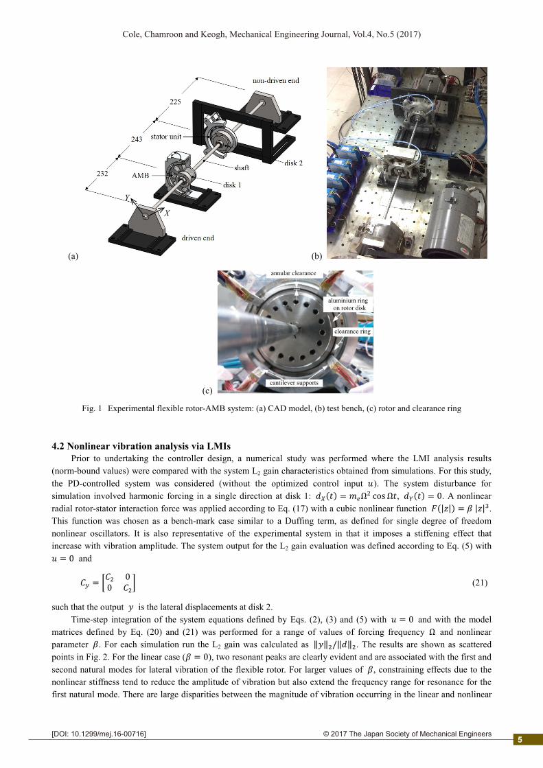
The described nonlinear H-infinity control approach was applied to the experimental rotor-AMB system shown in Fig. 1. The rotor is constructed from a steel shaft of length 700 mm and diameter 10 mm supported by ball bearings at each end. Two disks are fixed on the shaft. Disk 1 has mass 0.36 kg and forms the hub of the AMB. A backup bearing with radial clearance of 1 mm is also installed within the AMB. Disk 2, which has a mass 1.12 kg, is surrounded by a clearance ring which is compliantly supported by a force-sensing unit comprising four cantilever supports (stator unit), as shown in Fig. 1c. The ring may contact with a lubricated aluminium ring fixed to the rotor disk and having a radial clearance of 0.4 mm. Pairs of non-contact probes measure lateral displacement in orthogonal directions at both disks. The AMB was initially operated under PD feedback control. Large amplitude vibration leads to contact interaction between disk 2 and the surrounding ring and this contributes a nonlinear stiffness effect on rotordynamic behavior.
To model the system, the state vector may be partitioned according to and Y axis coordinates: = [ ]. The system inputs are the AMB forces applied at disk 1, = [ ] , the non-linear interaction force acting at disk 2, = [ ] , and external (unbalance) force disturbances represented by = [ ] . A model of rotor vibration may be defined in the form of Eqs (2) and (3) with = , = 00 , = = 00 , = 00 , (20)
where and are appropriate for input forces applied at disk 1 and disk 2, respectively. Similarly, is the output matrix appropriate to displacement at disk 2. For this system definition, the disturbance force acts in the same plane as the control force (at disk 1). For the nominal rotational speed range of 0-200 rad/s, which includes the
first critical speed, gyroscopic coupling between X-Z and Y-Z planes is negligible and hence = = 0. A system identification approach was used to obtain values for the system matrices in Eq. (20) based on frequency
response measurements for small-amplitude vibration. The system behaviour was found to be quite linear if contact at
the clearance ring was avoided. Note that the control forces act in addition to the feedback components from the PD controller, which is already accounted for within the model. The state sub-vectors , each have four states that
capture the first two natural modes for vibration in lateral planes. The PD control was implemented with a low-pass
filter. However, the filter dynamics did not significantly affect the system response over the bandwidth for vibration control (<1000 rads/s) and hence a fourth order model was appropriate. The PD controller gains were set to give only moderate stiffness and damping from the bearing so that the response characteristics are similar to those for the rotor
without the AMB operating. Hence, the main control effects will be derived from the optimized control component .
4
2© 2017 The Japan Society of Mechanical Engineers
Cole, Chamroon and Keogh, Mechanical Engineering Journal, Vol.4, No.5 (2017)
[DOI: 10.1299/mej.16-00716]
4.2 Nonlinear vibration analysis via LMIs Prior to undertaking the controller design, a numerical study was performed where the LMI analysis results
(norm-bound values) were compared with the system L2 gain characteristics obtained from simulations. For this study,
the PD-controlled system was considered (without the optimized control input ). The system disturbance for simulation involved harmonic forcing in a single direction at disk 1: ( ) = Ω cosΩ , ( ) = 0. A nonlinear
radial rotor-stator interaction force was applied according to Eq. (17) with a cubic nonlinear function (| |) = | | . This function was chosen as a bench-mark case similar to a Duffing term, as defined for single degree of freedom nonlinear oscillators. It is also representative of the experimental system in that it imposes a stiffening effect that increase with vibration amplitude. The system output for the L2 gain evaluation was defined according to Eq. (5) with = 0 and
= 00 (21)
such that the output is the lateral displacements at disk 2. Time-step integration of the system equations defined by Eqs. (2), (3) and (5) with = 0 and with the model
matrices defined by Eq. (20) and (21) was performed for a range of values of forcing frequency Ω and nonlinear parameter . For each simulation run the L2 gain was calculated as ‖ ‖ /‖ ‖ . The results are shown as scattered points in Fig. 2. For the linear case ( = 0), two resonant peaks are clearly evident and are associated with the first and
second natural modes for lateral vibration of the flexible rotor. For larger values of , constraining effects due to the nonlinear stiffness tend to reduce the amplitude of vibration but also extend the frequency range for resonance for the first natural mode. There are large disparities between the magnitude of vibration occurring in the linear and nonlinear
(a) (b)
(c)
Fig. 1 Experimental flexible rotor-AMB system: (a) CAD model, (b) test bench, (c) rotor and clearance ring
X
Y
clearance ring
aluminium ring on rotor disk
annular clearance
cantilever supports
5

2© 2017 The Japan Society of Mechanical Engineers
Cole, Chamroon and Keogh, Mechanical Engineering Journal, Vol.4, No.5 (2017)
[DOI: 10.1299/mej.16-00716]
cases for a frequency range 140-250 rad/s and it is this frequency range that will be a focus for controller design and testing.
For the LMI analysis, the system described by Eqs (20) and (21) was combined with an input weighting function,
as shown in Fig. 3. The transfer function ( ) is a stable approximation of the forcing function cosΩ given by ( ) = (22)
This resonant filter is used to probe the L2 gain characteristics for harmonic forcing. If is chosen sufficiently small then, for a stable linear system ( = 0), we have = sup ‖ ‖ = ( ) ( ) = sup ( ) ( ) ≈ ( Ω) (23)
For the nonlinear case, this frequency domain interpretation is no longer valid. Nonetheless, the value of the peak L2 gain provides a useful bound on the magnitude of vibration (in the sense of the L2 norm) under conditions of harmonic forcing. An upper bound on the value of the peak gain can be obtained by solving the LMI Eq. (19) with the smallest possible value of . Values for the peak-gain bound obtained by solving the LMI problem for a range of values of Ω are shown in Fig. 2. Note that for this analysis = 0 as the PD controller is already accounted for within the model and no additional control is being applied. For the LMI analysis, the forcing amplitude is not accounted for directly but is implicit in the choice of ̅. Larger forcing amplitude is associated with larger values of | | and hence, a larger value of ̅ = sup ( ( )/| ( )|) = sup (| ( )| ). For the results shown in Fig. 2, the LMI gain-bound was obtained using the actual value of ̅ from each simulation run. The gain-bound from the LMI analysis is seen to be sufficiently ‘tight’ to warrant its further application in the controller synthesis problem – which seeks to reduce the gain bound through application of an optimized feedback control law.
4.3 Robust feedback control synthesis For controller synthesis, the augmented plant structure shown in Fig. 4 was considered. Here, the output
weighting ( ) reflects the expected characteristics of the disturbance signals (as for the analysis case in Fig. 3). Note that ( ) is now applied at the output of the plant so that, for implementation, the states of ( ) can be reconstructed from measurement of . In the case study, we consider rotating unbalance as the main source of vibration excitation and seek to minimize vibration at disk 1 only. Hence, we may anticipate nonlinear behavior due to large amplitude vibration at disk 2. The weighting function is therefore chosen to penalize over a frequency range corresponding to rotational speeds 0-200 rad/s, but emphasizing a nominal operating speed of 190 rad/s.
Fig. 2 L2 gain calculated from simulation runs with harmonic forcing: results are shown for a selection of values for the
non-linear parameter . The peak L2 gain-bound obtained by solving LMI problem Eq. (16) is also shown
0 100 200 300 400 500 6000
0.05
0.1
0.15
0.2
0.25
0.3
0.35
0.4
forcing frequency (rad/s)
L 2 gai
n
L2 gain bound
from solving LMI problem
0
0.1
0.20.4
1
6

2© 2017 The Japan Society of Mechanical Engineers
Cole, Chamroon and Keogh, Mechanical Engineering Journal, Vol.4, No.5 (2017)
[DOI: 10.1299/mej.16-00716]
For linear controller design, the weighting function would be chosen so that | ( )| exceeds the multiplicative uncertainty in the plant (frequency response) model. According to the small gain theorem, if the closed loop system model (from to ) satisfies ‖ ‖ < 1, the actual closed loop system will then always be stable. Strictly, these arguments are appropriate for linear systems only. Nonetheless, limiting the peak L2 gain of the nonlinear system helps to create a controller that is more robust to model error (although an appropriate choice of to guarantee stability is harder to deduce). Note also that must be interpreted as an operator (signal-to-signal mapping) in this context rather than a transfer function. The synthesis problem then is to obtain a control law such that the peak L2 gain of the closed loop system is less than one. This is a nonlinear version of an H-infinity control problem, similar to the mixed sensitivity design paradigm, with the objective to achieve a closed loop system satisfying = < 1 (24)
A controller for which Eq. (24) holds will provide vibration attenuation performance with robust stability. The state-space model for the augmented plant has the same form as Eqs (2)-(5) but with new state vector , which combines the rotor states with weighting states and according to = [ ], as shown in Fig. 4.
Figure 5 shows the frequency response characteristics (singular values) for the linearized closed loop dynamics and , together with the inverse of the weighting functions and . The inverse weighting functions
exceed the maximum singular values over all frequencies, which agrees with Eq. (24). Hence, the required H-infinity performance and robustness properties are confirmed for the linearized system dynamics.
Fig. 3 The nonlinear rotordynamic model is augmented with a weighting function (disturbance model) for analytical
determination of the L2 gain under conditions of harmonic excitation
Fig. 4 Augmented plant for nonlinear H-infinity controller synthesis
102
103
104
-80
-70
-60
-50
-40
-30
-20
-10
0Singular Values
Frequency (rad/sec)
Sin
gula
r V
alue
s (d
B) W1(s)
(. )
( )
( )
(. )( )
7

2© 2017 The Japan Society of Mechanical Engineers
Cole, Chamroon and Keogh, Mechanical Engineering Journal, Vol.4, No.5 (2017)
[DOI: 10.1299/mej.16-00716]
5. Experimental results
Nonlinear H-infinity controllers were implemented and tested on the experimental system described in section 4.1. The designs and implementations were based on the system under initial PD feedback control. For comparison, a
linear H-infinity controller was synthesized using the LMI formulation with the reduced version of matrix Φ in Eq. (19). The same weighting functions were used for both types of controller (although scaling factors were adjusted to
obtain controllers giving similar levels of linear performance). It was found that the linear H-infinity controllers generally had good vibration attenuation characteristics over a low frequency range (0-200 rad/s), even for nonlinear operation. This can be explained by the increased damping for the first flexural mode. However, for certain choices of
, closed loop stability was not maintained when rotor interaction with the clearance ring occurred at disk 2. In contrast, the nonlinear H-infinity controller could maintain stability over the full range of linear and nonlinear operating conditions. It thus became clear that, for linear controller design, stability under nonlinear operation was difficult to
ensure and sensitive to the exact choice of weighting functions. So, the approach of dealing with nonlinear effects explicitly was clearly advantageous.
For a given feedback control system that is known to be stable for linear (small amplitude) vibration it may also be possible to check for potential instability using frequency response data. An alternative to the LMI analysis approach is to apply the Popov stability criterion (see Khalil (2000)). Strictly, this is appropriate only for scalar (single-input/single-output) nonlinear functions that satisfy a sector-bound condition. However, it may still be applied to the nonlinear rotor-stator interaction model given by Eqs (17) and (18) if rotordynamic coupling between axes is sufficiently weak. Then and axes may be considered separately and the Nyquist plot of the linear system (considering or as input and or as output) used to assess stability. These plots are shown for the test case system in Fig. 6. For the linear H-infinity controller design, the Nyquist curve crosses the negative real axis at = −0.26 and so, according to the Popov criterion, stability cannot be ensured if the nonlinear force function is such that / > − = 3.85 N/mm. Conversely, to guarantee stable vibration, the nonlinear function must satisfy the sector-bound condition 0 ≤ / ≤ − . For the nonlinear H-infinity controller the Nyquist curve does not cross the negative real axis and so stability of the system is always ensured, at least for the nominal model.
(a) (b)
Fig. 5 Results of nonlinear H-infinity controller design. Plots show frequency response characteristics for the linearized
closed loop system: (a) vibration attenuation performance (b) robust stability
101
102
103
104
-100
-80
-60
-40
-20
0
20
40
60
80
uncontrolled system Gyd
closed loop system Tyd
W1 -1
Singular Values
Frequency (rad/sec)
Sin
gula
r V
alue
s (d
B)
100
101
102
103
104
105
-60
-50
-40
-30
-20
-10
0
10
20
Tud
W2 -1
Singular Values
Frequency (rad/sec)
Sin
gula
r V
alue
s (d
B)
8

2© 2017 The Japan Society of Mechanical Engineers
Cole, Chamroon and Keogh, Mechanical Engineering Journal, Vol.4, No.5 (2017)
[DOI: 10.1299/mej.16-00716]
Fig. 7 Rotor vibration during steady speed rotation: (a) no rotor-stator contact interaction (linear case) (b) with rotor-stator
contact interaction (nonlinear case)
Figure 7 shows rotor vibration levels for constant rotational speed, quantified in terms of the RMS
displacements measured at disks 1 and 2. Figure 7a shows results for both linear and nonlinear H-infinity designs under linear operation (with no clearance ring fitted). The controllers gave similar results in terms of RMS vibration at disk 1, although the linear controller design gave reduced vibration for the nominal operating speed of 190 rad/s. The response behavior reflects the overall form and scaling of (see Fig. 5a). The vibration at disk 2, which is not included in the cost function, is noticeably different for the two controllers. Figure 7b shows results for nonlinear operation, with installation of the clearance ring at disk 2. The nonlinear H-infinity controller was effective for the full range of running speeds and unbalance conditions tested. The unbalance condition of the rotor was such that hard interaction with the clearance ring only occurred for higher speeds (>180 rad/s). For the linear H-infinity controller, the risk of
Fig. 6 Nyquist plots for linearized closed loop systems: transfer functions from input to output
(a) linear operation (without clearance ring) (b) nonlinear operation (with clearance ring)
-0.4 -0.3 -0.2 -0.1 0 0.1 0.2 0.3 0.4-0.4
-0.3
-0.2
-0.1
0
0.1
0.2
0.3
0.4Nyquist Diagram
Real Axis
Imag
inar
y A
xis
linear H
controller
nonlinear H
controller
0 50 100 150 2000
100
200
300
rotational speed (rad/s)
RM
S v
ibra
tion
( m
)
Disk 1
0 50 100 150 2000
200
400
600
800
rotational speed (rad/s)
RM
S v
ibra
tion
( m
) Disk 2
nonlinear H-infinity control
linear H-infinity control
0 50 100 150 200 2500
200
400
600
rotational speed (rad/s)
RM
S v
ibra
tion
( m
)
Disk 1
0 50 100 150 200 2500
200
400
600
800
rotational speed (rad/s)
RM
S v
ibra
tion
( m
)
clearance limit
Disk 2
nonlinear H-infinity control
PD controller
9
2© 2017 The Japan Society of Mechanical Engineers
Cole, Chamroon and Keogh, Mechanical Engineering Journal, Vol.4, No.5 (2017)
[DOI: 10.1299/mej.16-00716]
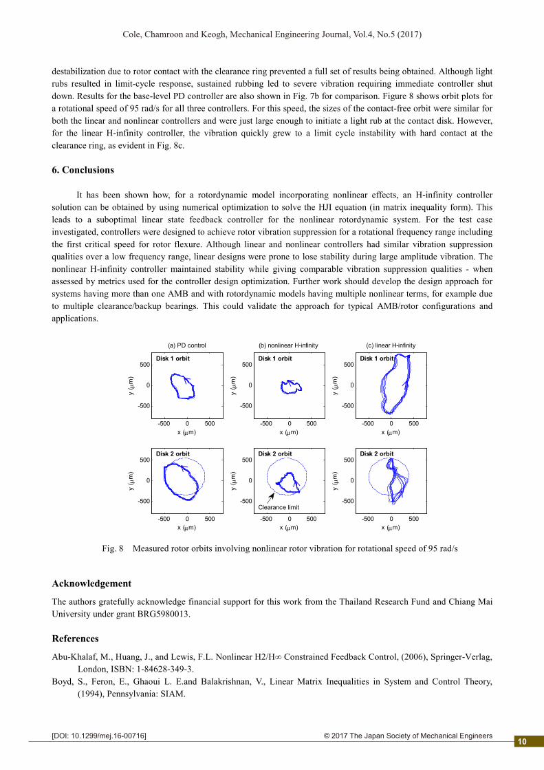
destabilization due to rotor contact with the clearance ring prevented a full set of results being obtained. Although light rubs resulted in limit-cycle response, sustained rubbing led to severe vibration requiring immediate controller shut down. Results for the base-level PD controller are also shown in Fig. 7b for comparison. Figure 8 shows orbit plots for a rotational speed of 95 rad/s for all three controllers. For this speed, the sizes of the contact-free orbit were similar for both the linear and nonlinear controllers and were just large enough to initiate a light rub at the contact disk. However, for the linear H-infinity controller, the vibration quickly grew to a limit cycle instability with hard contact at the clearance ring, as evident in Fig. 8c. 6. Conclusions
It has been shown how, for a rotordynamic model incorporating nonlinear effects, an H-infinity controller
solution can be obtained by using numerical optimization to solve the HJI equation (in matrix inequality form). This leads to a suboptimal linear state feedback controller for the nonlinear rotordynamic system. For the test case investigated, controllers were designed to achieve rotor vibration suppression for a rotational frequency range including the first critical speed for rotor flexure. Although linear and nonlinear controllers had similar vibration suppression qualities over a low frequency range, linear designs were prone to lose stability during large amplitude vibration. The nonlinear H-infinity controller maintained stability while giving comparable vibration suppression qualities - when assessed by metrics used for the controller design optimization. Further work should develop the design approach for systems having more than one AMB and with rotordynamic models having multiple nonlinear terms, for example due to multiple clearance/backup bearings. This could validate the approach for typical AMB/rotor configurations and applications.
Fig. 8 Measured rotor orbits involving nonlinear rotor vibration for rotational speed of 95 rad/s
Acknowledgement
The authors gratefully acknowledge financial support for this work from the Thailand Research Fund and Chiang Mai University under grant BRG5980013. References
Abu-Khalaf, M., Huang, J., and Lewis, F.L. Nonlinear H2/H∞ Constrained Feedback Control, (2006), Springer-Verlag, London, ISBN: 1-84628-349-3.
Boyd, S., Feron, E., Ghaoui L. E.and Balakrishnan, V., Linear Matrix Inequalities in System and Control Theory, (1994), Pennsylvania: SIAM.
-500 0 500
-500
0
500Disk 1 orbit
x (m)
y (
m)
(a) PD control
-500 0 500
-500
0
500
x (m)
y (
m)
Disk 2 orbit
-500 0 500
-500
0
500
(b) nonlinear H-infinity
Disk 1 orbit
x (m)
y (
m)
-500 0 500
-500
0
500
x (m)
y (
m)
Disk 2 orbit
Clearance limit
-500 0 500
-500
0
500
(c) linear H-infinity
x (m)
y (
m)
Disk 1 orbit
-500 0 500
-500
0
500
x (m)
y (
m)
Disk 2 orbit
10

2© 2017 The Japan Society of Mechanical Engineers
Cole, Chamroon and Keogh, Mechanical Engineering Journal, Vol.4, No.5 (2017)
[DOI: 10.1299/mej.16-00716]
Cade I. S., Sahinkaya, M. N., Burrows, C. R. and Keogh, P. S. An active auxiliary bearing control strategy to reduce the onset of asynchronous periodic contact modes in rotor/magnetic bearing systems, Trans. ASME, J. Eng. Gas Turbines and Power, Vol. 132, (2010), Art. No. 052502.
Chamroon, C., Cole, M.O.T. and Wongratanaphisan, T., An active vibration control strategy to prevent nonlinearly coupled rotor-stator whirl responses in multimode rotor-dynamic systems, IEEE Transactions on Control Systems Technology, Vol. 22, No. 3, (2014), pp. 1122-1129.
Cole, M.O.T. and Keogh, P.S. Rotor vibration with auxiliary bearing contact in magnetic bearing systems, Part 2: Robust synchronous control to restore rotor position, Proc. Instn. Mech. Engrs, Part C, Journal of Mechanical Engineering Science, Vol. 217, No. 4 (2003), pp. 393-409.
El-Shafai, A., Dimitri, A.S., Controlling journal bearing instability using active magnetic bearings, ASME J. Eng. Gas Turbines Power, Vol. 132, No. 1, (2010), art. no. 012502.
Inoue, T. Liu, J. Ishida Y. and Yoshimura, Y., Vibration control and unbalance estimation of a nonlinear rotor system using disturbance observer, ASME J. Vibr. Acoust., Vol. 131, (2009), Art. No. 031010.
Isidori, A. and Astolfi, A. Disturbance attenuation and H∞ control via measurement feedback in nonlinear systems, IEEE Transactions on Automatic Control, Vol. 37, No.9, (1992), pp. 1283-1293.
Karkoub, M. Robust control of the elastodynamic vibration of flexible rotor system with discontinuous friction, ASME J. Vib. Acoust., Vol. 133, (2011) art. no. 034501.
Khalil, H.K. Nonlinear Systems, 3rd edition. (2000) Pearson Education. Schweitzer, G., Maslen, E. (Eds.), Magnetic Bearings: Theory, Design and Application to Rotating Machinery, Chapter
12, (2009), Springer, Berlin, ISBN: 978-3-642-00496-4. Simon, A. and Flowers, G.T., Adaptive disturbance rejection and stabilisation for rotor system with internal damping,
International Journal of Acoustics and Vibrations, Vol. 13, No. 2, (2008), pp. 73-81. Sinha, P. K. and Pechev, A. N. Nonlinear H∞ controllers for electromagnetic suspension systems, IEEE Transactions
on Automatic Control, Vol. 49, No. 4, (2004), pp. 563-568. Van der Schaft, A.J. L2-Gain analysis of nonlinear systems and nonlinear state feedback H∞ control, IEEE
Transactions on Automatic Control, Vol. 37, No. 6, (1992), pp. 770-784. Appendix
Applying a congruency transformation with ( , , , ) to Eq. (16) followed by a change of variables = , = and Σ = Σ yields + − + 2 + Σ ++ Σ + −2 + Σ + Σ 0 00 − 00 0 − < 0 (A1)
By Schur complements (see Boyd et al., 1994), this is equivalent to + − + Σ ++ Σ + −2 + Σ + Σ 0 0 00 − 0 00 0 − 00 0 0 −< 0 (A2)
It can be seen that this inequality still has bilinear terms involving Σ. Although techniques for solving bilinear matrix inequalities (which are non-convex) can be used, the method used for this paper was to set Σ = and solve Eq. (A2) for selected values of the scalar . Repeatedly solving the LMI problem with a line-search over allowed a solution yielding the minimum value of to be obtained.
11