a feasibility assessment of magnetic bearings · pdf filenasa contractor report cr-189135 ......
TRANSCRIPT
NASA Contractor Report CR-189135 MTI 91TR53
A FEASIBILITY ASSESSMENT OF MAGNETIC BEARINGS FOR FREE-PISTON STIRLING SPACE POWER CONVERTERS
Dr. Peter W. Curwen, Dr. Dantam K. Rao, and Mr. Donald S. Wilson Mechanical Technology Incorporated 968 Albany-Shaker Road Latham, New York 121 10
June 1992
Prepared for Lewis Research Center Under Contract NAS3-26061
NASA
https://ntrs.nasa.gov/search.jsp?R=19930005727 2018-05-19T18:45:02+00:00Z

ACKNOWLEDGMENTS
The feasibility study reported herein was sponsored by t h e U.S. National Aeronautics and Space Administration (NASA), Lewis Research Center. Dr. D.P. Fleming was the NASA Project Manager. The MTI Project Manager was Dr. P.W. Curwen.
Technical contributors t o the study were:
*
Magnetic bearing design: Dr. H. Ming Chen and Mr. D.S. Wilson Magnetic bearing sensors and electronics: Mr. R.A. Dorman
Magnetic bearing RSSPC design engineering: Mr. J. Kralick
RSSPC performance analysis: Dr. M. Dhar
Dynamics code extension: Dr. J.A. Walowit (MTI Consultant)
Magnetic spring analysis: Dr. S. Bhate (MTI Consultant) Magnetic bearing literature survey: Dr. D.K. Rao.
Dr. Curwen was the principal author of this report. Mr. Wilson provided the tex t for Section 8.0. Dr. Rao was the author for the majority of Section 3.0.
i i i

SECTION
TABLE OF CONTENTS
PAGE
... ACKNOWLEDGMENTS ....................................................... 111
LIST OF FIGURES ........................................................... vii LIST OF TABLES ............................................................. ix 1.0 INTRODUCTION ......................................................... 1
1.1 Background ......................................................... 1 Reasons for Study ................................................... 3 1.2
2.0 RSSPC DESIGNS ......................................................... 5
2.2 Relative-Displacer RSSPC ............................................ 5 2.3 Performance Comparison of Gas Bearing RSSPC Designs ................. 7
2.1 Absolute-Displacer RSSPC ........................................... 5
3.0 MAGNETIC BEARING TECHNOLOGY REVIEW AND SELECTION .............. 9 Overview of Magnetic Suspension Technologies .......................... 9 Rotating versus Reciprocating Magnetic Bearing Experience ............. 11 Selection of Magnetic Bearing Type for RSSPC Study ................... 14
3.1 3.2 3.3
4.0 DESIGN OF MAGNETIC BEARINGS FOR RSSPC ............................ 17 4.1 4.2
Magnetic Bearing Configuration ...................................... 18 Power Piston Bearings .............................................. 19
4.3 Displacer Bearings ................................................. 2 1 Load Capacity and Power Consumption ......................... 2 1
4.2.1 Load Capacity and Power Consumption ......................... 19 4.2.2 Weights and Electromagnet Time Constant ..................... 19
4.3.1 4.3.2 Weights and Electromagnet Time Constant ..................... 23
5.0 INCORPORATION OF MAGNETIC BEARINGS INTO RSSPC DESIGNS .......... 25 5.1 Absolute-Displacer RSSPC .......................................... 25
5.1.1 Mechanical Design .......................................... 25 5.1.2 Heat Transfer .............................................. 27
5.2 Relative-Displacer RSSPC ........................................... 27 5.3 Magnetic Spring Evaluation .......................................... 30 5.4 Comparison of Magnetically Supported RSSPC Designs .................. 35
5.4.1 RSSPC Mass and Specific Mass ................................ 35 5.4.2 RSSPC Efficiency ........................................... 38
6.0 DYNAMICS OF RSSPC ENGINE-BEARING SYSTEMS ........................ 4 1 6.1 Undamped Open-Loop Natural Frequencies ............................ 4 1 6.2 RSSPC Dynamic Response ........................................... 43
6.2.2 6.2.3
6.2.1 Power Piston Dynamic Response .............................. 45 Displacer Dynamic Response .................................. 56 Conclusions on RSSPC Dynamics .............................. 58

TABLE OF CONTENTS (Continued)
SECTION PAGE
7.0 DISPLACEMENT SENSORS FOR MAGNETIC BEARINGS ..................... 65 7.1 Types of Sensors ................................................... 65 7.2 Sensor Requirements ............................................... 66 7.3 Selected Sensor .................................................... 67
8.0 ELECTRONICS FOR MAGNETIC BEARINGS ................................ 71 8.1 Closed-Loop System Configurations ................................... 71 8.2 Bearing Control and Power Electronics ................................ 74 8.3 Control Electronics System Packaging ................................ 77
9.0 CONCLUSIONS ......................................................... 83
10.0 RECOMMENDATIONS ................................................... 87
REFERENCES ............................................................... 89
vi
LIST OF FIGURES
NUMBER PAGE
3
7
a 9
10
11
12
13
14
15
16
17
i a
19
20
21
Design Layout of 25-kWe RSSPC Module Supported
Design Layout of Relative-Displacer RSSPC Module Supported
Power Flow Diagram for One Absolute-Displacer RSSPC Module
by Hydrostatic Gas Bearings ............................................ .2
by Magnetic Bearings ................................................... 6
with Hydrostatic Gas Bearings .......................................... .8
................. .' ...... .11
Eight-Pole, All-Electromagnetic, Active Magnetic Journal Bearing ............ .12
Configuration of Eight-Pole, All-Elec tro magne tic, Active Magnetic
Basic Electromagnetic Attraction Force Mechanism
Linear Bearings Used in Philips Laboratories' Split-Stirling Cryocooler .............................................. .13
Cross Section of Magnetic Bearing Pole Piece used in Philips Laboratories' Linear Bearing .................................... .13
Six-Pole, All-Electromagnetic, Active Magnetic Journal Bearing. ............. .16
Magnetic Bearing Electromagnet Configuration for RSSPC Displacer and Power Piston (Four Electromagnets per Bearing) ...................... . l a
Layout of Absolute-Displacer RSSPC with Power Piston Supported by Magnetic Bearings ........................................ .26
Cross-Section View of Magnetic Bearing Assembly for RSSPC Power Piston .............................................. .28
Layout of Relative-Displacer RSSPC with Power Piston and Displacer Supported by Magnetic Bearings ........................... .29
Cross-Section View of Magnetic Bearing Assembly for Relative-Displacer RSSPC ......................................... .3 1
Magnetic Spring Configuration for Displacer ............................... .33
Computed Force and Stiffness (per inch of circumferential length) versus Axial Displacement of Magnetic Spring. ........................... .33
Layout of Absolute-Plus-Relative-Displacer RSSPC with Magnetic Spring Incorporated in Displacer Assembly ..................................... .34
Open-Loop Natural Frequencies of Power Piston for Absolute-Displacer RSSPC ......................................... .42
Open-Loop Natural Frequencies of Displacer and Power Piston for Relative-Displacer RSSPC ......................................... .42
Stable Power Piston Response for Absolute-Displacer RSSPC with No Loading from Seals, Ports, Alternator, or Gravity. ..................... .48
Stable Power Piston Response for Absolute-Displacer RSSPC with Alternator Loading Only ............................................... 4a
Stable Power Piston Response for Absolute-Displacer RSSPC with Alternator Plus Gravity Loading.. ...................................... .49
vii

LIST OF FIGURES (Continued)
NUMBER PAGE
22
23
24
25
26
27
28
Unstable Power Piston Response for Absolute-DispTacer RSSPC
Stable Power Piston Response for Absolute-Displacer RSSPC with
Stable Power Piston Response for Absolute-Displacer RSSPC with
Unstable Power Piston Response for Relative-Displacer RSSPC with
Stable Power Piston Response for Relative-Displacer RSSPC with
Stable Power Piston Response for Relative-Displacer RSSPC with
Stable Displacer Response for Relative-Displacer RSSPC with
(Tc = 0.00045 sec) ..................................................... 50
Alternator, Gravity, Seal, and Port Loadings ............................. .50
Alternator, Seal, and Port Loadings (No Gravity Load). .................... .51
Seal and Port Loadings (Proportional Gain = 225,450 lbf/in.) ................ .56 Seal and Port Loadings (Proportional Gain = 263,025 lbf/in.) ................ .57 Seal, Port, and Gravity Loadings ....................................... .57
Seal, Port, and Gravity Loadings (Two Grooves in Expansion-to-Compression-Space Seal) .................................. .6 2
Seal and Port Loadings (One Groove in Expansion-to-Compression-Space Seal) .................................. .6 2
29 Unstable Displacer Response for Relative-Displacer RSSPC with
30
31
32
One of Two Capacitance Sensors Used to Measure Reciprocating Stroke
Measured Output A t Constant 254-pm (10-mil) Gap for CTPC Capacitance Sensor From 20 to 315OC Ambient Temperature.. ............. .68
Piston Supported by Four-Sector Active Magnetic Bearings with Common Coils for ac Control and dc Bias Currents (Only X-2 Plane Shown) ............................................... .72
Piston Supported by Four-Sector Active Magnetic Bearings with Separate Coils for ac Control and dc Bias Currents (Only X-2 Plane Shown) ............................................... .73
34 Typical Magnetic Bearing Control Loop ................................... .75 35 Sensor Electronics Circuit Board ......................................... .78 36 Control Electronics Circuit Board ........................................ .79 37 Power Amplifier Circuit Board ........................................... .80
38 dc-dc Converter Circuit Board ........................................... .80
of the CTPC Displacer ................................................. 67
33
viii
LIST OF TABLES
NUMBER PAGE
1
2
3 4
5
6
7
8
9
10
11
12
13
Types of Magnetic Force Mechanisms ...................................... 10 Comparison of Design and Performance Parameters
for the Philips Laboratories' Cryocooler and the RSSPC .................... 14
Magnetic Bearing Assessment ............................................. 15
Power Piston Magnetic Bearing with dc Bias .............................. 20
Displacer Magnetic Bearing with dc Bias
Sizing and Performance Data for a Representative RSSPC
Sizing and Performance Data for a Representative RSSPC ................................. 22
Piston and Displacer Parameters for Candidate RSSPC Configurations .......... 36
Mass of Magnetic Bearing Hardware for Candidate RSSPC Configurations (Including Sensors but Excluding Electronics) .............................. 37
Comparison of Predicted RSSPC Efficiencies With Hydrostatic Gas Bearings Versus Magnetic Bearings ........................ 39
Pressure Wave Parameters for Candidate RSSPC Configurations (Mean pressure of 15.03 MPa (2180.0 psia)) ................................ 44
Summary of Power Piston Dynamics Calculations for the Absolute-Displacer RSSPC .......................................... 46
Summary of Power Piston Dynamics Calculations for Relative-Displacer RSSPC .............................................. 52
Summary of Displacer Dynamics Calculations for Relative-Displacer RSSPC .............................................. 59
......... 81 Package Sizes for Control Electronics Circuitry (Per Piston Assembly)
ix

1.0 INTRODUCTION
This report describes work performed by Mechanical Technology Incorporated (MTI) under NASA Contract NAS3-26061, "A Feasibility Assessment of Magnetic Bearings for Free-Piston Stirling Space Engines." The work was performed over the period from July 1990 through August 1991. The objective of the effort was to assess the feasibility and efficacy of applying magnetic bearings to free-piston Stirling-cycle power conversion machinery of the type currently being evaluated for possible use in future long-term space missions.
1.1 Background
Under NASA Contract NAS3-25463, MTI is developing and demonstrating free-piston Stirling engine technology for converting thermal energy from a nuclear heat source into electrical energy. The goals of this technology are driven by anticipated mission require- m e n t s for long-life equipment that will be needed for lunar base, space station, and space exploration initiatives (SEI). Representative goals which impact power converter design requirements for these types of missions are:
Mission life of 60,000 hr
Power converter specific mass less than 6.0 kg/kWe Power conversion efficiency greater than 25% (net electric power out divided by thermal power delivered to the engine's heater head).
As part of the Stirling Space Power Converter (SSPC) program (NASA Contract NAS3- 25463), a Reference Stirling Space Power Converter (RSSPC) design is maintained and periodically updated. The RSSPC represents the preliminary design of a 50-kWe space power converter and, as such, embodies the latest advances in design concepts and tech- nology development. The 50-kWe power converter consists of two coaxially mounted free-piston Stirling engine/alternator modules, each of which generates 25-kWe of electric power. The coaxial arrangement of the two engine modules is used to achieve a dynamically balanced, low-vibration power conversion system. Figure 1 shows the design of one power conversion module as it existed at the start of the subject magnetic bearing feasibility study. Two of these modules, sharing a common expansion space, would constitute the complete RSSPC.
A major contributor to the total weight of a gas-cycle energy conversion system for space is the weight of the radiator used to reject thermal energy to space ambient. Heat is rejected to space ambient by radiation heat transfer. Therefore, the size and weight of the radiator are inversely related to the fourth power of the rejection temperature. To minimize radiator weight, the radiator should operate at the highest possible rejection temperature. System studies have established 500 K as a goal for the cycle rejection temperature. This translates to 525 K (485'F) as the cooler temperature for the Stirling engine power converter. In the absence of small auxiliary cooling loops rejecting at lower temperatures, 525 K then becomes the sink temperature for the "cold" end of the RSSPC. Accordingly, the engine's mechanical and electrical components, including the bearings and alternator, m u s t be designed to operate reliably at temperatures of the order of 525 K. This is one of the difficult technology challenges currently being addressed, and one that must also be addressed by any alternative component technology such as magnetic bearings.
1

B 4 Y cn
OLD a 4
w

1.2 Reasons for Study
The technology for the RSSPC is being developed and demonstrated under NASA Contract NAS3-25463 using a series of test engines. The Component Test Power Converter (CTPC) is the first of these engines and is currently in test. The CTPC is essentially a scaled-down version of the RSSPC design shown in Figure 1. The power rating of each CTPC module is 32.5-kWe, rather than the 25-kWe per module rating of the RSSPC.
The RSSPC shown in Figure 1, like the CTPC, is equipped w i t h hydrostatic (pressurized) helium gas bearings to support the reciprocating power piston and displacer assemblies without sliding contact. The source of pressurized helium for the bearings is derived from within the RSSPC itself. The displacer and power pistons, in addition to their primary Stirling cycle functions, also provide pressurized helium to the bearings through a system of inlet and discharge ports and associated internal plenums. One disadvantage of this arrangement is that pressurized helium is not immediately available a t engine start-up unless an auxiliary source of stored high-pressure helium (e.g., a tank wi th associated valves, plumbing, and controls) is used. The RSSPC and CTPC bearings are currently designed to operate with sliding contact during engine start-up. The duration of sliding contact will be about 0.1 sec (about seven reciprocation cycles). This represents the time required for the power piston stroke to build to the point where sufficient pressurized helium will be available to float the bearings.
To minimize the pumping power required to pressurize the hydrostatic bearings, the bearings must be designed wi th small radial clearances and small bearing feed orifices. For the RSSPC and CTPC, nominal radial bearing clearances range from 12.7 to 17.8 p m (0.0005 to 0.0007 in.). The bearing orifice diameters are 330 p m (0.013 in.). The power required to pressurize all of t h e hydrostatic bearings in one RSSPC module is predicted to be 485 W. This represents 1.7% of module output power based on an 89% alternator efficiency.
The self-contained hydrostatic bearing system contains only static elements, these being internal flow passages and plenums, flow control ports, bearing clearances, and bearing feed orifices. No electronic controls or moving parts (aside from the engine's pistons) are required. These attributes result in an inherent potential for high bearing system reliability. However, there are technical and cost issues associated with achieving th is potential. These issues may be summarized as follows:
0 The high cost associated with machining numerous close tolerance, concentric diameters to achieve both t h e required bearing clearances and the precision alignment of the bearings wi th respect to the close-clearance gas spring seals used in t he RSSPC
The need for extensive design and development effort to minimize and/or accommodate changes in bearing clearances due to differential thermal expansions as t h e bearings heat up to the 525 K operating temperature
The need for very high cleanliness standards to ensure that debris or particulate matter will not plug one or more of the small bearing orifices
3

The need to demonstrate (and perhaps develop) bearing surfacing materials that can survive sliding contact during a reasonable number of engine start/stop cycles without degradation of bearing performance, and without generation of wear debris that might plug the bearing orifices or the engine's regenerator matrix
An excessive penalty on overall RSSPC system efficiency due to the power required to provide the hydrostatic bearing flow.
*
Because of the above concerns associated with hydrostatic gas bearings, it is desirable to evaluate and compare the characteristics of alternative types of bearings for the RSSPC. Hydrodynamic gas bearings, squeeze-film gas bearings, and magnetic bearings are three possible alternatives. This report addresses the magnetic bearing alternative. Three frequently cited attributes of magnetic bearings can be immediately recognized as being advantageous to the RSSPC.
Magnetic bearings can be electrically energized (levitated) at any time, whether or not the RSSPC is operating (assuming that electric power is available). Accordingly, sliding contact of the bearings can be eliminated during RSSPC start-up and shutdown. Additionally, magnetic bearings would permit sustained RSSPC operation at very low strokes, which is not possible with the present hydrostatic gas bearings. This might be important for emergency conditions (non-RSSPC related) wherein major reductions in power system output may be required, but complete shutdown of the power conversion system is undesirable. Magnetic bearings can be designed with order-of-magnitude larger clearances than are required for gas bearings. This greatly reduces the problem of maintaining safe bearing clearances in the presence of differential thermal expansions arising from the 525 K operating temperature. It also permits some relaxation of mechanical manufacturing tolerances and associated machining costs, although this does not necessarily imply that a magnetic bearing system will be less expensive than a gas bearing system. Unfortunately, magnetic bearings will not eliminate the need for piston and displacer gas spring clearance seals and their attendant close tolerance machining and alignment requirements. Magnetic bearings will be significantly less susceptible to problems associated wi th debris and particulate matter. This results again from the relatively large clearances in magnetic bearings and from the fact that magnetic bearings do not have small orifices that are subject to plugging.
Additional potential advantages of magnetic bearings are:
Improved overall RSSPC system efficiency as a result of reduced bearing system losses Simplified RSSPC design resulting from elimination of close-clearance gas bearings Reduced RSSPC development costs.
Whether or not any of these latter three potential advantages will, in fact, be realized can only be determined by detailed comparison of RSSPC designs based on both magnetic bearings and other candidate bearing options.

2.0 RSSPC DESIGNS
As discussed in Section 1.0, the RSSPC is a 50-kWe power converter consisting of two identical, coaxially mounted, 25-kWe engine/alternator modules that operate in phase opposition for cancellation of dynamic forces. Two hydrostatic gas bearing versions of the RSSPC existed at the start of this study. One version (shown as Figure 1 in Section 1.0) is based on using a screen regenerator in the engine, while the other (MTI drawing 1042DSK-0160) is based on using a foil regenerator. While the use of a foil regenerator results in a smaller, lighter RSSPC package, the two designs are otherwise conceptually the same. For the purposes of this study, both of these versions are referred to as "absolute-displacer" RSSPC designs because the displacer is sprung via gas springs from the stationary engine frame.
Subsequent to initiation of this study, an alternative RSSPC concept was introduced as part of the continuing RSSPC design evolution under the SSPC program (Contract NAS3-25463). This version differs from the absolute-displacer versions in that the displacer is sprung via gas springs from the power piston, rather than from the engine frame. Accordingly, this version is referred to as the "relative-displacer" RSSPC design. The following paragraphs briefly describe the absolute- and relative-displacer RSSPC design arrangements with respect to features that must be accommodated by any alternative bearing system.
2.1 Absolute-Displacer RSSPC
A cross-section view of one engine/alternator module of the absolute-displacer RSSPC was shown earlier in Figure 1. The displacer assembly of the absolute RSSPC contains five clearance (Le., noncontacting) gas seals; four of these are close-clearance seals while the fifth is a moderate-clearance seal. The close-clearance seals are required for the two displacer gas springs and consist of a rod seal and piston seal for each spring. The moderate-clearance seal is the expansion-to-compression-space seal around the OD of the displacer. These seals must be retained in any magnetic bearing version of the absolute-displacer RSSPC unless a means for eliminating one or both of the displacer gas springs can be found.
The power piston assembly of the absolute RSSPC contains two close-clearance gas seals, both located on the OD of the power piston. One of these seals is associated with the internal pressurization system for the hydrostatic gas bearings and would not be required in a magnetic bearing machine. The second seal is the piston gas spring seal. This seal must be retained in a magnetic bearing machine unless some other means of energy storage is used that does not require a gas seal.
Each gas spring in any RSSPC design will require mid-stroke porting to maintain the correct mean pressure conditions within the gas spring chamber. Any magnetic bearing system must accommodate the required gas spring porting. These ports can usually be incorporated within the gas spring seal regions, in which case, additional seals are not required.
2.2 Relative-Displacer RSSPC
While preliminary design parameters and associated performance predictions for the relative-displacer RSSPC have been documented, a layout drawing for the hydrostatic gas bearing version of the relative-displacer RSSPC does not currently exist. However, the features of the design can be described with reference to the conceptual magnetic
5

bearing layout of this machine as shown in Figure 2. The immediately obvious advantage of this design is that the number of displacer clearance seals is reduced from five to two. One of these is the expansion-to-compression-space seal, the same as in the absolute-displacer RSSPC. The remaining seal is a displacer-to-piston seal that seals the internal "relative gas spring" cavity of the displacer.
Aside from any performance considerations, the relative-displacer concept represents a considerable reduction in the mechanical complexity and manufacturing cost of the displacer assembly. The "post and flange" component of the absolute-displacer engine is eliminated. This allows the displacer and power piston assemblies to be supported by one integral structure rather than by two mechanically joined structures as required in the absolute-displacer RSSPC.
Conceptually, the power piston assemblies of the absolute- and relative-displacer RSSPCs are the same except for the displacer-to-piston clearance seal required for the relative-displacer RSSPC. Both pistons require a close-clearance gas spring seal that must be retained in a magnetic bearing RSSPC.
Gas
Figure 2. Design Layout of Relative-Displacer RSSPC Module Supported by Magnetic Bearings
6
92029 1053DSK-0002

2.3 Performance Comparison of Gas Bearing RSSPC Designs
The net thermodynamic engine efficiency (defined as gross Stirling cycle pneumatic power divided by thermal power supplied to the heater head) and the overall RSSPC conversion efficiency (defined as alternator net electric output power divided by therdal power supplied to the heater head) for the reference gas bearing absolute- and relative- displacer RSSPC design concepts are as follows:
Predicted RSSPC Efficiencies Absolute Displacer Relative Displacer
Thermodynamic engine efficiency: 33.3% 34.2% (with foil regenerators)
Overall efficiency: 27.4% 28.0% (assuming same gas bearing losses for both design concepts)
The thermodynamic engine efficiencies listed above are consistent comparisons of the thermal-to-pneumatic energy conversion characteristics of the basic Stirling cycle for the absolute- and relative-displacer RSSPC concepts. The slightly higher thermodynamic efficiency of the relative RSSPC concept results from reduced compression-space seal losses. The reduced seal losses are a consequence of reduced leakage area and reduced pressure amplitude across the leakage path due to the phase relationships of this engine.
The overall RSSPC efficiencies listed above account for gas spring losses, alternator losses, bearing-related losses, and other auxiliary losses. Figure 3 shows a power flow diagram for the reference absolute-displacer RSSPC. The predicted overall efficiency of the absolute-displacer RSSPC is based on hydrostatic gas bearings wherein the calculated bearing-related losses for one 25-kWe power module are 485 W. Most of these bearing- related losses actually occur within the gas springs since the bearings are pressurized by the gas springs. The overall efficiency value for the relative-displacer RSSPC is also based on an allowance of 485 W for bearing losses. However, this allowance has not yet been verified by a detailed design of hydrostatic bearings for this engine. There is, in fact, some question as to whether a hydrostatic bearing system can be incorporated into the displacer of the relative-displacer RSSPC concept without significant additional mass and efficiency penalties.
The 485 W of bearing-related losses, if converted to electrical power at 89% alternator efficiency, represents 432 W of lost electrical output, or 1.7% of alternator rated output power. In terms of overall RSSPC efficiency, the bearing- related losses represent 0.47 efficiency points, or a 1.7% reduction in overall efficiency. Since performance of the relative-displacer RSSPC is competitive with the absolute-displacer RSSPC and the mechanical design simplifications are attractive, i t was decided that the relative-displacer RSSPC should be included in the subject feasibility study.
7

Rejected Heat t- 60.05 kW Heat Input Thermodynamic Cycle 91.1 kW -i (0.332)
Gross PV Power 30.24 kW
Displacer Drive Piston Drive - (0.972) (0.958) 1.27 kW 28.97 kW
I
0.17 kW ,/ \ 1.10 kW 0.500 kW I Alternator
(0.89)
Numbers in parentheses are eficienues. ?IkW 92027( M)
Figure 3. Power Flow Diagram for One Absolute-Displacer RSSPC Module with Hydrostatic Gas Bearings
a

3.0 MAGNETIC BEARING TECHNOLOGY REVIEW AND SELECTION
A literature search was conducted under Task 1 of the subject feasibility study. The objectives were to:
Update information on the state of the art of magnetic bearings for rotating and reciprocating machinery Make an initial assessment as to the types of magnetic bearings with the most potential for applicability to the linear free-piston RSSPC.
The literature search was conducted as part of MTI's continuing internal magnetic bearing development activity and is documented in MTI Report 90TR46, "Assessment of Magnetic Bearing Concepts for Stirling Space Engines," by Dr. Dantam K. Rao. A copy of th is report was provided to the NASA Program Manager under Contract NAS3-26061. Sections 3.1 and 3.2 highlight the pertinent results of this literature search and are either direct quotes or paraphrased excerpts from this report.
3.1 Overview of Magnetic Suspension Technologies
Magnetic suspension technology is basically concerned with methods for converting electromagnetic power from a stationary body into mechanical power on a moving body to keep the moving body "suspended" in assigned directions. The type of magnetic suspension is determined by the characteristics of rigid body motion executed by the suspended body under the action of external forces and torques and possibly rigid body constraints.
In some applications, the rigid body motion is completely prevented by external constraints (such as clamped beams or structures). In those applications, the purpose of magnetic suspension is to control specified flexible body vibrations. The relevant technology is called "smart structures" or "vibration control" technology.
In other applications (e.g., pistons and rotating shafts), the magnetically suspended body is permitted to execute certain rigid body motions. These desired rigid body motions are dictated by external forces other than the magnetic suspension forces. In these cases, magnetic suspension is expected to work in harmony with these other external forces to achieve the desired functioning of the suspended body. Depending on the specific motions controlled by external agents and those controlled by magnetic suspension forces, magnetic suspension can be broadly divided into four categories: rotary magnetic bearings, linear magnetic bearings, gimbal magnetic bearings, and magnetic levitation (MAGLEV) technology.
The magnetic forces produced by magnetic suspension devices arise from the interaction of magnetic fields between a flux-creating primary component mounted on the stationary body and a flux-receiving secondary component mounted on the suspended body. A sensor and control system will sometimes be needed to keep the suspended body in stable equilibrium. If superconducting components are excluded, there are two options for primary components and four options for secondary components, resulting in ten distinct force-generating mechanisms. Table 1 shows how these ten force-generating mechanisms can be broadly divided into four categories: attraction force, repulsion force, shear force, and bidirectional force.
9
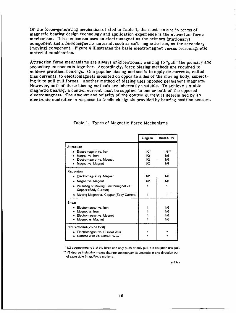
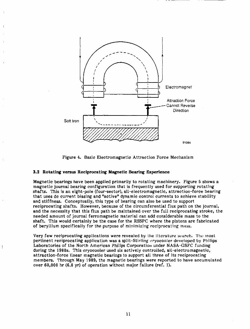
Of the force-generating mechanisms listed in Table 1, the most mature in terms of magnetic bearing design technology and application experience is the attraction force mechanism. This mechanism uses an electromagnet as the primary (stationary) component and a ferromagnetic material, such as soft magnetic iron, as the secondary (moving) component. Figure 4 illustrates the basic electromagnet versus ferromagnetic material combination.
Attraction force mechanisms are always unidirectional, wanting to llpull" the primary and secondary components together. Accordingly, force biasing methods are required to achieve practical bearings. One popular biasing method is to apply dc currents, called bias currents, to electromagnets mounted on opposite sides of the moving body, subject- ing it to pull-pull forces. Another method of biasing uses opposed permanent magnets. However, both of these biasing methods are inherently unstable. To achieve a stable magnetic bearing, a control current must be supplied to one or both of the opposed electromagnets. The amount and polarity of the control current is determined by an electronic controller in response to feedback signals provided by bearing position sensors.
Table 1. Types of Magnetic Force Mechanisms
10
Attraction Electromagnet vs. Iron Magnet vs. Iron Electromagnet vs. Magnet Magnet vs. Magnet
Repulsion Electromagnet vs. Magnet Magnet vs. Magnet Pulsating or Moving Electromagnet vs. Copper (Eddy Current) Moving Magnet vs. Copper (Eddy Current)
Shear Electromagnet vs. Iron Magnet vs. Iron Electromagnet vs. Magnet Magnet vs. Magnet
Bidirectional (Voice Coil) Electromagnet vs. Current Wire Current Wire vs. Current Wire
~
Degree
112' 112 112 112
112 112 1
1
1 1
Instability
116" 116 116 116
416 4 6
1
1
116 116 116 116
? ?
'112 degree means that the force can only push or only pull, but not push and pull.
of a possible 6 rigid body motions. "116 degree instability means that this mechanism is unstable in one direction out
BlTR53
L Electromagnet
Attraction Force
I I
f / Cannot Reverse f Direction
91064
Figure 4. Basic Electromagnetic Attraction Force Mechanism
3.2 Rotating versus Reciprocating Magnetic Bearing Experience
Magnetic bearings have been applied primarily to rotating machinery. Figure 5 shows a magnetic journal bearing configuration that is frequently used for supporting rotating shafts. This is an eight-pole (four-sector), all-electromagnetic, attraction-force bearing that uses dc current biasing and "active" dynamic control currents to achieve stability and stiffness. Conceptually, this type of bearing can also be used to support reciprocating shafts. However, because of the circumferential flux path on the journal, and the necessity that this flux path be maintained over the full reciprocating stroke, the needed amount of journal ferromagnetic material can add considerable mass to the shaft. This would certainly be the case for the RSSPC where the pistons are fabricated of beryllium specifically for the purpose of minimizing reciprocating rnms.
Very few reciprocating applications were revealed by 1 tie literutui-c sctcirch. ' I ' tw most pertinent reciprocating application was a split-Stirling cryocooler developed by Philips Laboratories of the North American Philips Corporatioil under NASA-GSFC funding during the 1980s. This cryocooler used six actively controlled, all-electromagnetic, attraction-force linear magnetic bearings to support all three of its reciprocating members. Through May 1989, the magnetic bearings were reported to have accumulated over 60,000 hr (6.8 yr) of operation without major failure (ref. 1).
11

Air
Figure 5. Eight-Pole, All-Electromagnetic, Active Magnetic Journal Bearing
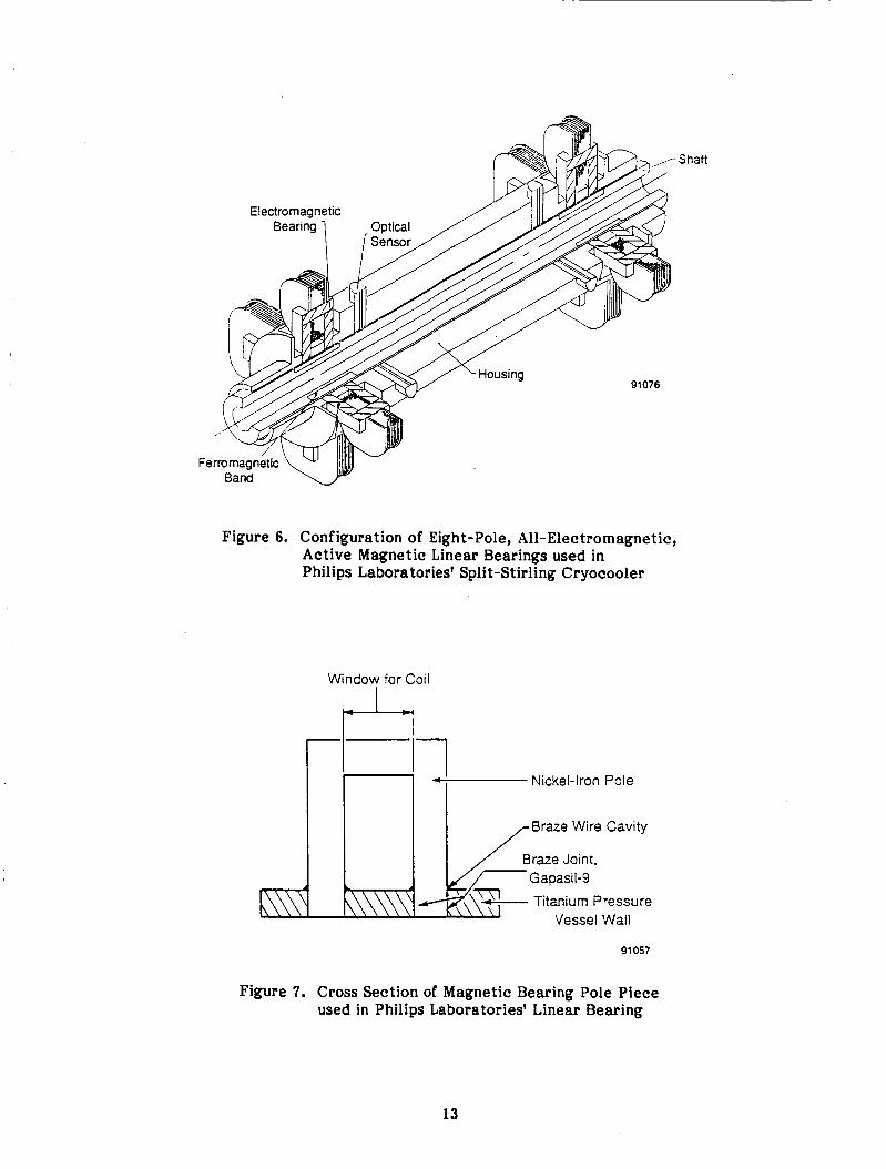
Figure 6 shows the basic four-sector magnetic bearing configuration used in the Philips Laboratories' cryocooler. Figure 7 shows a more detailed cross section of the pole piece used in each electromagnet. The pole piece construction was dictated by the decision to locate all coils for the electromagnets outside of the cryocooler's hermetically sealed helium environment. Accordingly, the poles were fabricated from solid nickel-iron ferro- magnetic material and brazed into the titanium pressure vessel wall to maintain the hermetic pressure seal. The flux path in the journal of the Philips Laboratories' bearing is axial, rather than circumferential. However, the fact that the ferromagnetic portion of each journal consists of a full circular band means that no advantage was taken of the axial flux path to reduce reciprocating mass. Because of the small size and low frequency of this machine, reciprocating mass was probably not a primary concern as it is wi th the RSSPC.
Table 2 presents a comparison of pertinent design and performance parameters for the Philips Laboratories' cryocooler and the RSSPC. It is seen that the RSSPC parameters 'epresent a significant advance beyond the cryocooler requirements in almost all upects. The most significant difference between the two applications is that the RSSPC )earings must operate in a 525 K (485'F) environment, whereas the cryocooler bearings qerate in ambient temperatures of about 300 K (80'F). Additionally, the almost ourfold increase in reciprocating frequency of the RSSPC implies that frequency esponse and stability characteristics of the RSSPC active bearing controllers must be aref ully assessed.
12
Shaft
Figure 6. Configuration of Eight-Pole, All-Electromagnetic, Active Magnetic Linear Bearings used in Philips Laboratories' Spli t-Stirling Cr yocooler
Window for Coil
J-4
Nickel-Iron Pole
Braze Wire Cavity
Braze Joint, Gapasil-9
Titanium Pressure Vessel Wall
91 057
Figure 7. Cross Section of Magnetic Bearing Pole Piece used in Philips Laboratories' Linear Bearing
13

Table 2. Comparison of Design and Performance Parameters for the Philips Laboratories' Cryocooler and the RSSPC
Parameter
Temperature (K) Axial Stroke (rnm) Frequency (Hz) Mass of Pistons (kg)
Piston Diameter (mrn) Radial Clearances (rnm)
Philips Cryocooler
300 5.3 to 13.9 18 0.36 to 1.9 0.019 25 to 37
RSSPC
525 28 to 32 70 3.5 to 20.4 0.012 to 0.018 135 to 162
91TRB
Scale Factor
1.8 2.3 3.9 10.7 0.6 4.4
3.3 Selection o€ Magnetic Bearing Type for RSSPC Study
As part of the assessment study documented in MTI Report 90TR46, a relative comparison of the maturity and potential payoffs of various types of magnetic bearings was performed. Maturity was assessed in terms of the number of years of development behind each type of bearing and the number of units in service. Payoffs were assessed in terms of bearing size, weight, and power consumption. While the comparison was based on an extensive review of magnetic bearing literature, a large amount of engineering judgement was nonetheless necessary to make the comparisons.
Table 3 shows the results of the relative comparison. The highest ranked bearing type is the four-electromagnet configuration, which is an eight-pole (four-sector) bearing with a circumferential flux path on the journal and two electromagnets per axis placed on opposite sides of the rotor as shown in Figure 5. This configuration is well established, and its behavior is well documented in the literature.
The second-ranked bearing type is the axial flux path configuration, which is an eight- pole (four-sector) bearing with an axial flux path on the journal as shown in Figure 6. Except for the direction of the journal flux path, this bearing is essentially the same as the highest-ranked bearing. Its second-place ranking results primarily from the fact that fewer of these units are in service. For reciprocating bearings, the axial flux path feature reduces the amount of lamination iron incorporated into the journal. This is particularly important for the RSSPC application where the requirement for minimum reciprocating mass necessitates that the entire power piston and alternator plunger carrier be fabricated from beryllium.
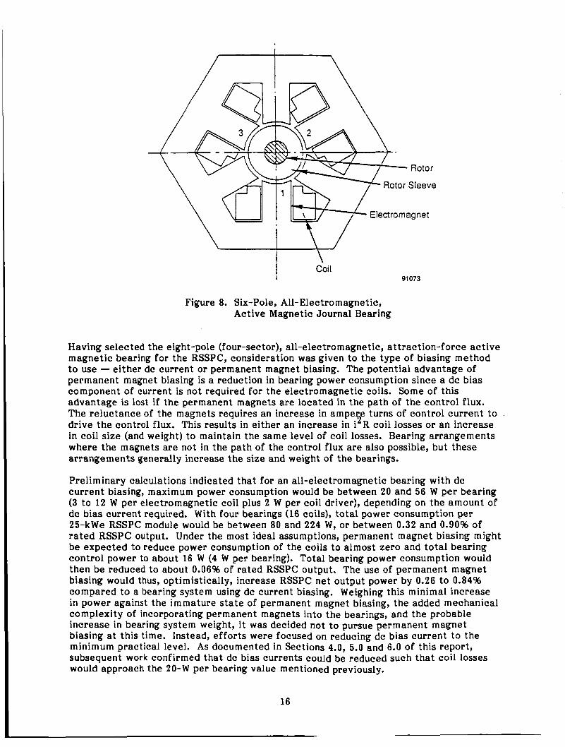
The third-ranked bearing type is the three-electromagnet configuration, which is the six- pole (three-sector) bearing shown in Figure 8. One advantage of this configuration is that only three power amplifiers, rather than four, are needed to drive the three electromagnets. Some additional control circuitry is needed for this arrangement to determine the required ac control currents to be applied to each electromagnet. Nonetheless, the reliability of the six-pole bearing may be higher than that of the eight- pole bearing because of the reduced number of power amplifiers. Since six-pole bearing configurations are not well characterized in the literature nor in MTI's experience, it was decided to l imi t the RSSPC study to eight-pole (four-sector) magnetic bearings.
14

0 0 ( ? % 0 0
P
a 2 3 - 0
15
I Coi I 91073
Figure 8. Six-Pole, All-Electromagnetic, Active Magnetic Journal Bearing
Having selected the eight-pole (f our-sec tor), all-elec tro magne tic, attrac tion-f orce active magnetic bearing for the RSSPC, consideration was given to the type of biasing method to use - either dc current or permanent magnet biasing. The potential advantage of permanent magnet biasing is a reduction in bearing power consumption since a dc bias component of current is not required for the electromagnetic coils. Some of this advantage is lost if the permanent magnets are located in the path of the control flux. The reluctance of the magnets requires an increase in ampe e turns of control current to . drive the control flux. This results in either an increase in 1 R coil losses or an increase in coil size (and weight) to maintain the same level of coil losses. Bearing arrangements where the magnets are not in the path of the control flux are also possible, but these arrangements generally increase the size and weight of the bearings.
.5
Preliminary calculations indicated that for an all-electromagnetic bearing with dc current biasing, maximum power consumption would be between 20 and 56 W per bearing (3 to 12 W per electromagnetic coil plus 2 W per coil driver), depending on the amount of dc bias current required. With four bearings (16 coils), total power consumption per 25-kWe RSSPC module would be between 80 and 224 W, or between 0.32 and 0.90% of rated RSSPC output. Under the most ideal assumptions, permanent magnet biasing might be expected to reduce power consumption of the coils to almost zero and total bearing control power to about 16 W (4 W per bearing). Total bearing power consumption would then be reduced to about 0.06% of rated RSSPC output. The use of permanent magnet biasing would thus, optimistically, increase RSSPC net output power by 0.26 to 0.84% compared to a bearing system using dc current biasing. Weighing this minimal increase in power against the immature state of permanent magnet biasing, the added mechanical complexity of incorporating permanent magnets into the bearings, and the probable increase in bearing system weight, it was decided not to pursue permanent magnet biasing at this time. Instead, efforts were focused on reducing dc bias current to the m i n i m u m practical level. As documented in Sections 4.0, 5.0 and 6.0 of this report, subsequent work confirmed that dc bias currents could be reduced such that coil losses would approach the 20-W per bearing value mentioned previously.
16
4.0 DESIGN OF MAGNETIC BEARINGS FOR RSSPC
As discussed in Section 3.0, four-sector active magnetic bearings using four electro- magnets with dc current biasing were selected for application to the candidate RSSPC designs. Prior to proceeding with detailed bearing design calculations, the following general guidelines were established to govern the design process.
e Maximum Bearing Load Capacities. Missions for the SSPC (or for any other dynamic space power conversion system) do not exist at this time. Accordingly, there were no mission requirements or specifications that could be used to establish maximum load requirements for the RSSPC magnetic bearings. A rather arbitrary decision was made to evaluate magnetic bearing designs based on a 7% l imi t load factor. Maximum Displacer and Power Piston Radial Displacements. Clearance seals for the displacer and power piston gas springs establish the maximum allowable dynamic radial excursions of the displacer and power piston assemblies during RSSPC operation. Since the seals should not rub during steady-state operation, it was decided that maximum radial excursions should be limited to 25% of the design radial clearance of the seals. This would allow a reasonable margin for accommodation of various factors that will determine actual geometry and mean eccentricities of the seals during RSSPC operation. These factors include distortions due to differential thermal expansions, long-term dc shifts in sensor calibrations, and accommodation of quasi-steady-state bearing loads such as might be imposed by station-keeping maneuvers. Changes to RSSPC Design to Incorporate Magnetic Bearings. It was recognized that changes to the displacer and power piston designs would be required in order to accommodate magnetic bearings. Such changes would be permissible provided they did not result in a degradation of RSSPC thermodynamic performance, or an increase in the dimensions of the RSSPC pressure shell. Magnetic Bearing Materials. Selection of materials for electromechanical design of magnetic bearings would be limited to those materials deemed to be acceptable for use in the CTPC being developed under Contract NAS3-25463.
* Location of Magnetic Bearing Electronics. Solid-state electronics operating at 25OoC are not currently feasible. Accordingly, low-temperature coolant fluid penetrations through the RSSPC pressure shell would be required to cool any magnetic bearing electronics located within the RSSPC pressure shell. Alternatively, the bearing electronics could be located external to the RSSPC pressure shell where ambient conditions can be more easily maintained at state- of-the-art levels for electronic components. Externally located electronics would result in greatly improved accessibility of the electronic modules for servicing or replacement. The price for this accessibility would be the need for a large number of electrical coil and sensor leads that must hermetically penetrate the RSSPC pressure shell. From a system reliability standpoint, it was assumed that external location of the electronics would be preferable. However, this assumption was not subjected to any rigorous reliability assess- ment.
Based on the above guidelines, magnetic bearing design calculations were made for the displacer and power piston of the candidate RSSPC arrangements. The selected bearing designs are documented in the following sections.
17
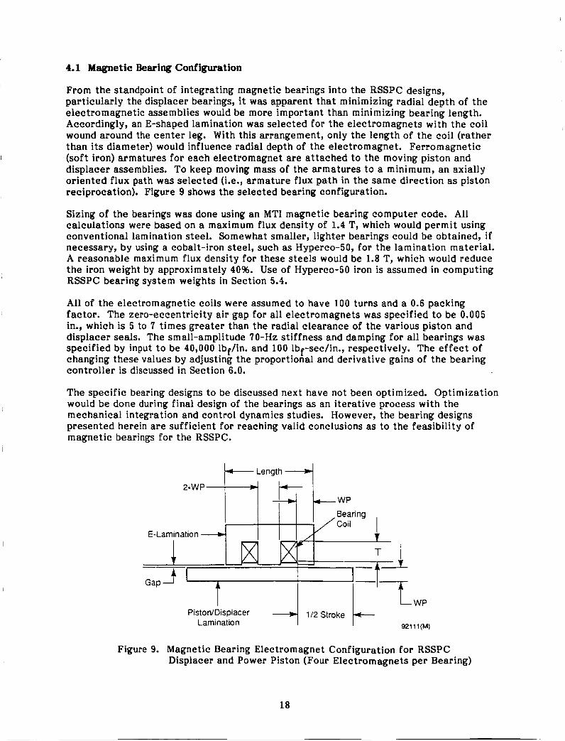
4.1 Magnetic Bearing Configuration
From the standpoint of integrating magnetic bearings into the RSSPC designs, particularly the displacer bearings, it was apparent that minimizing radial depth of the electromagnetic assemblies would be more important than minimizing bearing length. Accordingly, an E-shaped lamination was selected for the electromagnets with the coil wound around the center leg. With this arrangement, only the length of the coil (rather than its diameter) would influence radial depth of the electromagnet. Ferromagnetic (soft iron) armatures for each electromagnet are attached to the moving piston and displacer assemblies. To keep moving mass of the armatures to a minimum, an axially oriented flux path was selected (Le., armature flux path in the same direction as piston reciprocation), Figure 9 shows the selected bearing configuration.
Sizing of the bearings was done using an MTI magnetic bearing computer code. All calculations were based on a maximum flux density of 1.4 T, which would permit using conventional lamination steel. Somewhat smaller, lighter bearings could be obtained, if necessary, by using a cobalt-iron steel, such as Hyperco-50, for the lamination material. A reasonable maximum flux density for these steels would be 1.8 T, which would reduce the iron weight by approximately 40%. Use of Hyperco-50 iron is assumed in computing RSSPC bearing system weights in Section 5.4.
All of the electromagnetic coils were assumed to have 100 turns and a 0.6 packing factor. The zero-eccentricity air gap for all electromagnets was specified to be 0.005 in., which is 5 to 7 times greater than the radial clearance of the various piston and displacer seals. The small-amplitude 70-Hz stiffness and damping for all bearings was specified by input to be 40,000 lbf/in. and 100 lbf-sec/in., respectively. The effect of changing these values by adjusting the proportional and derivative gains of the bearing controller is discussed in Section 6.0.
The specific bearing designs to be discussed next have not been optimized. Optimization would be done during final design of the bearings as an iterative process with the mechanical integration and control dynamics studies. However, the bearing designs presented herein are sufficient for reaching valid conclusions as to the feasibility of magnetic bearings for the RSSPC.
E-Lamination
Piston/Displacer + 112 Stroke 921 1 1 (M) Lamination
Figure 9. Magnetic Bearing Electromagnet Configuration for RSSPC Displacer and Power Piston (Four Electromagnets per Bearing)
18

4.2 Power Piston Bearings
4.2.1 Load Capacity and Power Consumption
Input and output parameters from the MTI magnetic bearing computer code for a representative RSSPC power piston bearing are listed in Table 4. Sizing was based on a bearing diameter of 4.7 in., which is necessarily smaller than the piston diameter since the bearings are located inside the piston skirt. Overall E-lamination length is 2.0 in. Calculations were made for dc bias currents of 1.0, 1.5, and 2.0 A.
The output section of Table 4 shows the maximum load capacity of one piston bearing to be 274 lbf. This maximum load capacity corresponds to one electromagnet operating at 1.4-T flux density (total coil current of 2.817 A) and the opposing electromagnet operat- ing at zero flux density (zero coil current). A t a dc bias current of 2.0 A, the open-loop side-pull gradient of the bearing would be -110,300 lbf/in. To achieve the input-specified net positive bearing stiffness of 40,000 lbf/in., an open-loop proportional gain of 150,300 lbf/in. must be used.
Assuming a power piston mass of 45 lb, equally distributed on two bearings, the maximum bearing load corresponding to a load factor of 7 g would be 158 lb per
have to be about 275,000 lbf/in., which would require open-loop proportional gains of the order of 385,000 lbf/in. As demonstrated in Section 6.0, gains of this magnitude may result in unstable bearings. The bearings would probably require increased pole area, and hence size, to meet a 7-g stiffness requirement.
bearing. To prevent contacting of the piston gas spring seal, the bearing sti f fness would
Dc power consumption per bearing due to the dc bias current varies from 12.1 W at 1.0 A to 48.4 W at 2.0 A (coil losses only). While these coil losses may seem high compared to other magnetic bearing applications, it must be remembered that these losses are based on a coil temperature of 275OC (527OF). At this temperature, the resistivity of copper is twice its room temperature value.
Total power consumption in the coils will depend on the magnitude of the bearing control current as determined from bearing system dynamic analysis. Assuming a bearing displacement amplitude of 0.5 mil, Table 4 predicts a maximum dynamic control current amplitude of 0.29 A. Power loss due to this control current would be 0.5 W per bearing. Thus, the power dissipation due to the control current can be neglected. The amount of dc bias required will depend on the magnitude of the small-amplitude stiffness required; higher stiffnesses will require higher dc bias currents and higher proportional gains. If dynamic analysis shows that a bearing stiffness of 40,000 lbf/in. is acceptable and that dynamic bearing displacements will not exceed 0.001 in., then a 1.0-A dc bias current can be used, and coil losses will be about 12.2 W per bearing.
4.2.2 Weights and Electromagnet Time Constant
A breakdown of weights for the electromagnetic parts of one piston bearing is given in Table 4. Total weight of the stationary iron and coils for one bearing is approximately 1.36 kg (3.0 lbm). For a stop-to-stop piston displacement range of 1.4 in., total weight of moving iron for one bearing is approximately 1.03 kg (2.27 lb ). Total electromagnetic weight for two power piston magnetic bearings will be about T.78 kg (10.5 lbm). This weight represents an ideal lower limit since it does not include any structure associated with mounting or locating the electromagnetic parts.
19

Table 4. Sizing and Performance Data for a Representative RSSPC Power Piston Magnetic Bearing with dc Bias
SLOAD DI
CRATIO ARATIO LENGTH
GAP B A T
DWIRE INSUL F R U NTURN IBlAS KBRG BBRG
HZREF RMAX
0.0 4.7 0.5 0.6 2.0
0.005 goo00
0.02 0.005
0.6 100 2.0
40000 100 70
0.0005
NI IT
CLOAD PSI
LWlRE R L
W A I T WP
HEIGHT WIDTH APOLE
S T
DP DJ
W C U W F E S WTTrM
DlBlAS I1 13 61 63
FORCE1 FORCE3
KI K M CD CE cv
DYNl LDlDT
UR KICD
281.7 2.8 1 7
25-88 274.3
720.6 3.026
4 . 4 2 0.3
0.7625 2.032
0.4 0.2604
5.31 5.3
0.2907 2.71 6 2.1 67
0 .o 2.0 2.0
0.0389
2.438
63800 63800 137.9 137.9 275.7
1103OO 545.1 4906
0.3627 0.284 4.858
0.01 29 150300
0.0 4.7 0.s 0.6 2.0
0.005 90000
0.02 0.005
0.6 100 1.5
4oOoo 1 00 70
0.0005
28 i .7 2.817 274.3 25.88 720.6 3.026
27.24 0.3
0.7625 2.032 2.438
0.4 0.2604
5.31 5.3
0.2907 2.71 6 2.1 67
0 .o 1.5 1 .5
0.0389
47850 47850 77.54 77.54 206.8 62040 493.4 e441
0.4a36 0.2687
4.596 0.01 29 10 2000
0.0 4.7 0.s 0.6 2.0
0.005 90000
0.02 0.005
0.6 100 1 .o
40000 1 00 70
0.0005
28 t .7 2.817 274.3
720.6 3.026
0.0389 12.11
0.3 0.7625
2.032
0.4 0.2604
5.31 5.3
0.2907 2.71 6 2.1 67
0.0 1.0 1 .o
31900 3 1 900 34.46 34.46 137.9
27570 490.2 441 1
0.7254 0.292:
5.002 0.01 29 67570
25.88
2.438
STATIC LOAD, LB PISTON BASE DIAMETER, IN CIRCUMFERENTIAL POLE OCCUPANCY RATIO AXIAL TOTAL POLE LENGTHNNGTH
CONCENTRIC AIR GAP, IN CORE MAT'L SATURATION FLUX DENSITY, LINES/IN' '2 BARE COPPER WIRE DIAMETER, IN TOTAL WIRE INSUUTION THICKNESS, IN FILL FACTOR O f COIL IN SLOTS NO. OF COIL TURNS BIAS CURRENT, AMPERE STIFFNESS AT REFERENCE FREQUENCY, LBAN DAMPING AT REFERENCE FREQUENCY, LB-SECnN REFERENCE FREQUENCY. HERTZ (A CRITICAL SPEED) MAXIMUM RADIAL VIBRATION AMPLITUDE. IN
E-POLE LENGTH IN AXIAL DIRECTION. IN
IT X NTURN. AMPERE-TURN TOTAL CURRENT, AMPERE LOAD CAPACTTY. L6 CLOAD/(DJ*LENGTH). LBIIN"2 WIRE LENGTH PER MAGNET, IN RESISTANCE PER MAGNET, OHM INDUCTANCE PER MAGNET, HENRY TOTAL COIL HEAT GENERATED PER ERG, W A l T AXIAL POLE WIDTH OF AN END-LEG OF *E-# IN POLE PROJECTED HEIGHT, IN POLE PROJECTED WIDTH, IN TOTAL PROJECTED POLE AREA. IN"2 SLOT AXIAL WIDTH, IN SLOT RADIAL HEIGHT, IN POLE SURFACE INNER DIAMETER, IN PISTON OUTER DIAMETER, IN TOTAL WEIGHT OF COPPER PER BEARING. L9 TOTAL WEIGHT OF STATOR IRON PER BEARING. LB TOTAL WEIGHT OF MOVING IRON PER BEARING. LB ADDITIONAL WAS CURRENT IN LOADED SECTOR, A BIAS CURRENT IN LOADED SECTOR, A BIAS CURRENT IN OPPOSITE SECTOR, A FLUX DENSITY IN LOADED SECTOR. LINEflN"2 FLUX DENSITY IN OPPOSITE SECTOR. LINEAN 2 TOTAL FORCE OF LOADED SECTOR, LB TOTAL FORCE OF OPPOSITE SECTOR, LB CURRENT STIFFNESS. LBlAMPERE
OPEN-LOOP PROPORTIONAL GAIN AT REF. FREQ..A/IN OPEN-LOOP INTEGRAL GAIN AT REF. FREQ..A/IN/S OPEN-LOOP DERIVATIVE GAIN AT REF. FREQ.,A-SIIN DYNAMIC CURRENT AT REF. FREQ. FOR RMAX Oi3BlT. A L'DI/DT AT REF. FREQ. FOR RMAX ORBIT, VOLT TlME CONSTANT. S OPEN-LOOP BEARING STIFFNESS (KI'CD). LEAN
NEGATIVE MAGNETIC SIDE-PUU GRADIENT, LBAN
91TR53
20

The inductance and room temperature coil resistance of each electromagnet will be about 0.039 H and 1.5 ohm, respectively. These values yield an intrinsic room temperature time constant for each electromagnet of 0.026 sec. At the RSSPC operat- ing temperature, coil resistance will increase to about 3.0 ohm with a corresponding reduction in time constant to 0.013 sec.
4.3 Displacer Bearings
4.3.1 Load Capacity and Power Consumption
Input and output parameters from the MTI magnetic bearing code for a representative RSSPC displacer bearing are listed in Table 5. Sizing w a s based on a displacer diameter of 5.0 in. and an overall E-lamination length of 1.0 in. Calculations were made for dc bias currents of 2.0, 3.0, and 4.0 A.
The output section of Table 5 shows the maximum load capacity of one displacer bearing to be 69.9 lbf. This maximum load capacity corresponds to one electromagnet operating at 1.4-T flux density (total coil current of 5.63 A), and the opposing electromagnet operating at zero flux density (zero coil current). At a dc bias current of 4.0 A, the open-loop side-pull gradient of the bearing would be -28,100 lbf/in. To achieve the input- specified net positive bearing stiffness of 40,000 lbf/in., an open-loop proportional gain of 68,100 lbf/in. must be used.
Assuming a displacer mass of 8 lb primarily carried by one bearing, the maximum load corresponding to a load factor of v g would be 56 lbf per bearing. To prevent contacting of the displacer gas spring seal, the bearing stiffness would have to be about 56,000 lbf/in., which would require open-loop proportional gains of the order of 124,000 lbf/in. As demonstrated in Section 6.0, stable bearing operation appears to be feasible at gains of this magnitude. Displacer bearings sized to the dimensions given in Table 5 would probably meet a 7-g stiffness requirement.
Dc power consumption per bearing (four coils) due to the dc bias current varies from 12.2 W at 2.0 A to 49 W at 4.0 A based on copper resistivity at 275'C (527'F). Total power consumption will depend on the magnitude of the bearing control current as determined from dynamic analysis of the bearing system. Assuming a bearing displacement amplitude of 0.5 mil, Table 5 predicts a dynamic control current amplitude of 1.83 A at 2 A dc bias and 1.15 A at 4 A dc bias. Power loss due to this control current would be between 2.0 and 5.1 W per bearing. While not negligible, this loss is small compared to the dc bias power. The amount of dc bias required will depend on the magnitude of the small-amplitude stiffness required; higher stiffnesses will require higher dc bias currents and higher proportional gains. If dynamic analysis shows that a bearing stiffness of 40,000 lbf/in. is acceptable and that dynamic bearing displacements will not exceed 0.001 in., then a 2.0-A dc bias current can be used, and coil losses will be about 12.6 W per bearing.
21

Table 5. Sizing and Performance Data for a Representative RSSPC Displacer Magnetic Bearing with dc Bias
SLOAD DI
CRATIO ARATlO LENGTH
GAP BSAT
OWIRE INSUL F F I U NfURN BIAS KBRG BERG
HZREF RMAX
0.0 5.0 0.25 0.6 1 .o
0.005 9oooO 0.02
0.005 0.6 50 4.0
40000 100 70
0.0005
... o f l p m ... NI IT
CLOAD PSI
LWIRE R L
W A l T WP
HEIGHT WIDTH APOLE S T DP DJ
wrcu W E S W E M
DlBlAS I1 13 81 B3
FORCE1 FORCE3
KI K M CD CE cv
DYNl LDIOT
U R KICD
281.7 5.634 69.92 13.1 9 182.1 0.765 0.0025 48.96 0.1 5
0.461 4 1.036
0.621 6 0.2
0.2604 5.31 5.3
0.0735 0.379 0.3606
0.0 4.0 4.0
63800 63800 35.14 35.14 35.14 281 10 1938 17450 2.846 1.154 1.258
0.0032 681 10
0.0 5.0 0.2s 0.6 1 .o
0.005 90000 0.02 0.005 0.6 50 3 -0
40000 100 70
0.0005
281.7 5.634 69.92 13.19 182.1 0.765 0.0025 27.54 0.1 5
0.46 14 1.036
0.621 6 0.2
0.2604 5.31 5.3
0.0735 0.379 0.3606
0.0 3.0 3 .O
47850 47850 19.77 19.77 26.35 15810
21 18 19060 3.794 1.348 1.47
0.0032 558 10
0.0 5.0
0.25 0.6 1 .o
0.005 goo00 0.02
0.005 0.6 50 2.0
40000 100 70
0.0005
281.7 5.634 69.92 13.19 182.1 0.765 0.0025 12.24 0.15
0.4614 1.036
0.621 6 0.2
0.2604 5.3 1 5.3
0.0735 0.379 0.3606
0.0 2.0 2.0
31900 31900 8.785 8.785 17.57 7028 2677 24090 5.692 1.832 1.998
0.0032 47C30
STATIC LOAD, LB PISTON BASE DIAMETER, IN CIRCUMFERENTIAL POLE OCCUPANCY RATIO AXIAL TOTAL POLE LENGTHUNGTH
CONCENTRIC AIR GAP, IN CORE MAT'L SATURATION FLUX DENSIN, LINESIIN"2 BARE COPPER WIRE DIAMETER, IN TOTAL WIRE INSULATION THICKNESS. IN FILL FACTOR OF COIL IN SLOTS NO. OF COIL TURNS BIAS CURRENT, AMPERE STIFFNESS AT REFERENCE FREQUENCY. LBAN DAMPING AT REFERENCE FREQUENCY, LB-SEC/lN REFERENCE FREQUENCY. HERTZ (A CRITICAL SPEED) MAXIMUM RADIAL VIBRATION AMPLITUDE, IN
E-POLE LENGTH IN AXIAL DIRECTION. IN
IT X NTURN, AMPERE-TURN TOTAL CURRENT, AMPERE LOAD CAPACl7-Y. LB CLOAD/(DJ*LENGTH). LEAN* '2 WIRE LENGTH PER MAGNET, IN RESISTANCE PER MAGNET, OHM INDUCTANCE PER MAGNET, HENRY TOTAL COIL HEAT GENERATED PER ERG. W A l T AXIAL POLE WIDTH OF AN ENDLEG OF -E-, IN POLE PROJECTED HEIGHT, IN POLE PROJECTED WIDTH, IN TOTAL PROJECTED POLE AREA, IN"2 SLOT AXIAL WIDTH, IN SLOT RADIAL HEIGHT. IN POLE SURFACE INNER DIAMETER, IN PISTON OUTER DIAMETER. IN TOTAL WEIGHT OF COPPER PER BEARING. LB TOTAL WEIGHT OF STATOR IRON PER BEARING. LB TOTAL WEIGHT OF MOVING IRON PER BEARING. LB ADDITIONAL BIAS CURRENT IN LOADED SECTOR, A BIAS CURRENT IN LOADED SECTOR. A BIAS CURRENT IN OPPOSITE SECTOR. A FLUX DENSITY IN LOADED SECTOR, LINE/lN'*2 FLUX DENSITY IN OPPOSlTE SECTOR. UNEIIN''2 TOTAL FORCE OF LOADED SECTOR, LB TOTAL FORCE OF OPPOSITE SECTOR, LB CURRENT STIFFNESS, LBlAMPERE NEGATIVE MAGNETIC SIDE-PULL GRADIENT, LBAN OPEN-LOOP PROPORTIONAL GAIN AT REF. FREQ..AIIN OPEN-LOOP INTEGRAL GAIN AT REF. FREQ.,AIINIS OPEN-LOOP DERIVATIVE GAIN AT REF. FREQ..A-S/IN DYNAMIC CURRENT AT REF. FREQ. FOR RMAX ORBIT. /
L'DImT AT REF. FREO. FOR RMAX ORBIT. VOLT TIME CONSTANT, S OPEN-LOOP BEARING STIFFNESS (KI 'CDI. LEIIN
91TR53
22

4.3.2 Weights and Electromagnet Time Constant
A breakdown of weights for the electromagnetic parts of one displacer bearing is given in Table 5. Total weight of the stationary iron and coils for one bearing is approximately 0.2 kg (0.45 lbm). For a stop-to-stop displacer stroke of 1.4 in., total weight of moving iron for one bearing is approximately 0.19 kg (0.41 lb ). Total electromagnetic weight for two displacer magnetic bear,ings wi l l be about 0 .7 f kg (1.72 lb ). This weight represents an ideal lower limit since it does not include any strucgre associated with mounting or locating the electromagnetic parts.
The inductance and room temperature coil resistance of each electromagnet will be about 0.00247 H and 0.383 ohm, respectively. These values yield an intrinsic room temperature time constant for each electromagnet of 0.00645 sec. At the RSSPC operating temperature, coil resistance will increase to about 0.765 ohm with a corresponding reduction in time constant to 0.00323 sec.
23
5.0 INCORPORATION OF MAGNETIC BEARINGS INTO RSSPC DESIGNS
Initial designs of magnetic bearings for the RSSPC displacer and power pistons were presented in Section 4.0. This section describes the integration of these bearing designs into the candidate absolute- and relative-displacer RSSPC design layouts.
5.1 Absolute-Displacer RSSPC
5.1.1 Mechanical Design
Figure 10 shows a cross-section layout of one 25-kWe power module for the absolute- displacer RSSPC with the power piston supported by magnetic bearings. Magnetic bearings supporting the displacer are not shown in this layout. After considerable effort to incorporate magnetic bearings into the displacer assembly, it was concluded this could be done only by increasing the diameter of the RSSPC cooler and regenerator to allow OD mounting of the bearing electromagnets. This would also require increasing the RSSPC pressure shell diameter. The result of these modifications would be reduced RSSPC efficiency and increased weight, both of which were unacceptable options.
Attempts to internally mount the electromagnets at the dome end of the displacer were likewise unsuccessful because of the numerous passages and ports associated with operat- ion of the gas springs. These passages and ports are located in the post-and- flange support structure for the displacer. This is the structure to which the electromagnets would also have to be mounted.
Total displacer gas spring losses for one absolute-displacer RSSPC module are predicted to be 1.27 kW (hysteresis, leakage, porting, and shuttle). Because of these high losses, consideration was given to replacing the displacer gas springs wi th a magnetic spring. The results of a magnetic spring feasibility study, to be discussed shortly, were similarly not attractive. Accordingly, internally pumped hydrostatic bearings had to be retained for the displacer.
As shown in Figure 10, mounting of the bearing electromagnets inside the bore of the power piston appears feasible. Eight electromagnets are mounted on an arbor that, in turn, is bolted to the end of the power piston cylinder. This mounting arrangement requires the attachment points between the power piston and alternator plunger to straddle the arbor-to-cylinder mounting tabs and, consequently, requires that rotation of the power piston be prevented. It has been demonstrated in the CTPC program, and before that in the Space Power Research Engine (SPRE) program, that a strong anti- rotation torque is provided by the magnetic circuit design of the alternator. This anti- rotation torque is currently used in the CTPC to maintain circumferential alignment of the targets for the piston stroke sensors, and would provide sufficient anti-rotation torque for the magnetic bearing support concept shown in Figure 10. When energized, the magnetic bearings themselves will provide anti-rotation torque. Accordingly, circumferential orientation of the bearings relative to the alternator should be such that both components will cog the power piston to the same position.
OllffB, 49 INTENTIONALLY BLANK

d 7-l
2 1 bn
Ere .-
26

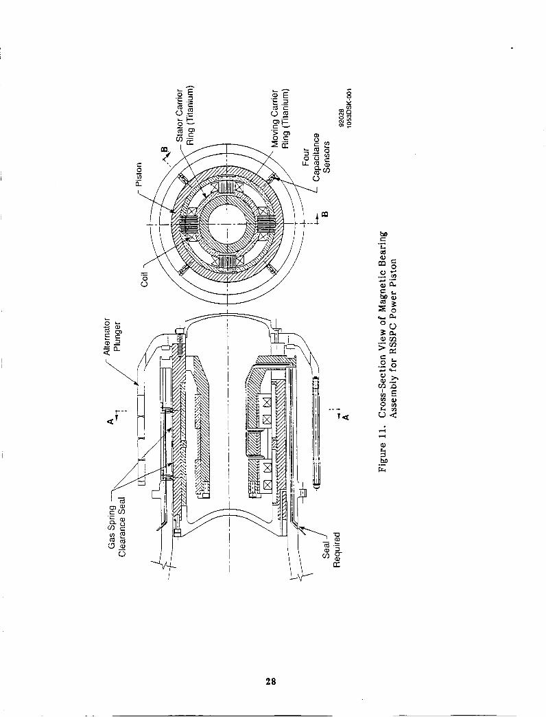
As depicted in Figure 11, both the moving iron armatures and the stationary E-lamination stacks for each of the eight electromagnets would be fabricated as packets of magnetic laminations welded into carrier rings made of titanium. The lamination carrier rings, together wi th bearing spacer rings, would then be shrunk into the ID of the beryllium piston and onto the OD of the stationary mounting arbor. The shrink-fitted parts would be axially locked into position by bolted flanges. Finish machining of the ID and OD surfaces of the piston and lamination packs would be done subsequent to this assembly. Since beryllium has a higher coefficient of thermal expansion than titanium, the shrink- f i t interference at room temperature would be of the order of 0.010 in. Careful design of the resulting composite structures, particularly the piston structure, would be required to minimize differential expansion distortions at RSSPC operating temperature and to ensure long-term dimensional stability.
5.1.2 Heat Transfer
Depending on the amount of dc bias current required, coil losses for the power piston bearings will range from 12.2 to 48.5 W per bearing. Two heat sinks are available for these losses: the RSSPC cycle cooler and the alternator cooler. To get to these sinks, the losses must be transferred across the electromagnet's air gap to the piston and then conducted through the piston to the cylinder wall and/or the compression space. The closest heat sink is the alternator cooler. Since helium flow for alternator cooling travels axially along the OD of the cylinder, most of the electromagnet's losses will be transferred from the cylinder OD into the alternator cooling flow and rejected into the alternator cooler.
Surface temperature of the cylinder OD, as predicted from SSPC thermal analysis under Contract NAS3-25463, will be about 28OoC. Based on conservative calculations for a maximum bearing loss of 49 W, the temperature rise from the cylinder OD surface to the center of an electromagnet's coil will be about 3OoC, giving a maximum coil temperature of about 31OoC. While this is less than the 325OC maximum temperature predicted for the alternator coils, it falls in the same category as the alternator coils in the sense that a proven wire insulation that will last for 60,000 hr has not yet been identified. Mechanical design of the electromagnet's coils, particularly the means for holding them in position while maintaining good thermal coupling between the coils and the E- lamination stacks, will probably be the most difficult aspect of magnetic bearing design for the RSSPC. This is solely the result of the temperature levels involved.
The losses from the bearing electromagnets are distributed in a roughly axisymmetric manner. The total radial temperature drop from the ID of the beryllium piston to the OD of the beryllium cylinder is conservatively computed to be about 3OC. However, since most of this drop will occur across the clearance of the piston gas spring seal, a detailed thermal analysis would be required before committing to magnetic bearings to ensure that thermal distortions in the clearance of the piston gas spring seal would not be a problem.
5.2 Relative-Displacer RSSPC
Figure 1 2 shows a cross-section layout of one 25-kWe power module for the relative- displacer RSSPC with both the power piston and displacer supported by magnetic bearings. The magnetic bearing arrangement for the power piston is essentially the same as discussed previously for the absolute-RSSPC machine and need not be discussed further here.
27
I
I I I I I I I I I
j
74 74
ho Frc .-
28

e 0 c1 v)
a .-
N
29

When Figures 10 and 12 are compared, it becomes obvious that the relative-displacer RSSPC represents a considerable reduction in mechanical complexity and manufacturing cost of the displacer assembly. The post-and-flange support structure of the absolute- displacer engine is eliminated. This allows the displacer and power piston assemblies to be supported by one integral structure rather than by two mechanically joined structures as required by the absolute-displacer RSSPC. Additionally, the number of displacer clearance seals is reduced from five to two. The expansion-to-compression-space seal is one of the remaining seals, which is the same as in the absolute-displacer RSSPC. The other is a displacer-to-piston seal that seals the internal relative-gas-spring cavity of the displacer.
With elimination of the post-and-flange support component, it becomes feasible to incorporate magnetic bearings into the displacer without modifications to the RSSPC cooler or regenerator. However, the length of the RSSPC pressure shell must be increased slightly. The eight bearing electromagnets are mounted around the OD of the "cold" end of the displacer. This results in the center of gravity of the displacer being slightly overhung from the bearings, causing one bearing to carry most of the displacer load if operated in a transverse l-g field. However, as discussed in Section 4.0, the magnetic bearings would be able to support 7-g load factors in this configuration. As shown in Figure 13, assembly of the displacer magnetic bearings would follow the same technique previously described for the power piston armatures. The eight electro- magnets are mounted via a titanium stator carrier ring into the integral beryllium displacer body housing that also forms the power piston cylinder. This permits good thermal coupling to be obtained between the E-laminations and housing.
Also depicted in Figure 13 is a possible alternative method of mounting the armature lamination packs. In this case, the lamination packs would be welded into titanium frames that would then be shrunk into dove-tail slots machined into the OD of the displacer piston. This mounting method would reduce bearing assembly weight and could be applied to the stator electromagnet assemblies, as well as to the power piston magnetic bearings. The disadvantages of this mounting method are the higher machining expense and possibly greater thermal distortion effects.
Depending on the amount of dc bias current used, coil losses for the displacer bearings will range from 12.6 to 51 W per bearing. It is clear from Figure 12 that these losses will be transferred through the support housing to the RSSPC compression space gas and subsequently rejected through the RSSPC cycle cooler. Temperature of the support housing in the region of the displacer bearings will be essentially the same as that of the power piston cylinder wall. However, thermal resistance from the support housing to the center of the displacer electromagnet's coils will be less than that of the power piston coils since the coil losses do not have to be transferred across the bearing air gaps. Consequently, maximum temperature of the displacer coils will be slightly less than that of the power piston coils. Nonetheless, the wire insulation and coil design difficulties will be the same.
5.3 Magnetic Spring Evaluation
The mass of the displacer for the reference absolute-displacer RSSPC design is 3.5 kg (7.72 lb ). The axial spring stiffness required to achieve correct displacer dynamics is 4050 lbpin. This stiffness is provided by two gas springs integrally designed into the displacer. As mentioned previously, the presence of these gas springs was a major obstacle to incorporating magnetic bearings into the displacer assembly. Additionally, the losses associated with these gas springs are 1.1 kW (4.4% of rated alternator output).
30

J
l
I I I I
31
32
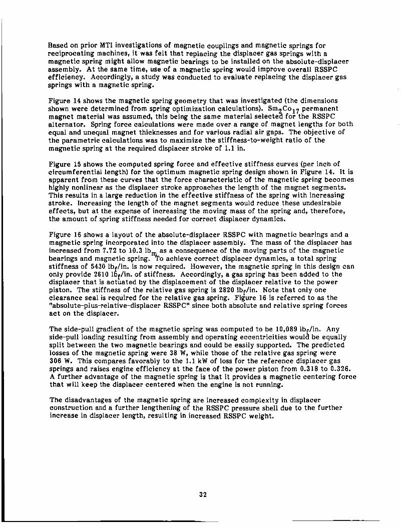
Based on prior MTI investigations of magnetic couplings and magnetic springs for reciprocating machines, i t was felt that replacing the displacer gas springs with a magnetic spring might allow magnetic bearings to be installed on the absolute-displacer assembly. A t the same time, use of a magnetic spring would improve overall RSSPC efficiency. Accordingly, a study was conducted to evaluate replacing the displacer gas springs with a magnetic spring.
Figure 14 shows the magnetic spring geometry that was investigated (the dimensions shown were determined from spring optimization calculations). Sm C017 permanent
alternator. Spring force calculations were made over a range of magnet lengths for both equal and unequal magnet thicknesses and for various radial air gaps. The objective of the parametric calculations was to maximize the stiffness-to-weight ratio of the magnetic spring at the required displacer stroke of 1.1 in.
magnet material was assumed, this being the same material selecte ?i for the RSSPC
Figure 15 shows the computed spring force and effective stiffness curves (per inch of circumferential length) for the optimum magnetic spring design shown in Figure 14. It is apparent from these curves that the force characteristic of the magnetic spring becomes highly nonlinear as the displacer stroke approaches the length of the magnet segments. This results in a large reduction in the effective stiffness of the spring with increasing stroke. Increasing the length of the magnet segments would reduce these undesirable effects, but at the expense of increasing the moving mass of the spring and, therefore, the amount of spring stiffness needed for correct displacer dynamics.
Figure 16 shows a layout of the absolute-displacer RSSPC with magnetic bearings and a magnetic spring incorporated into the displacer assembly. The mass of the displacer has increased from 7.72 to 10.3 lb as a consequence of the moving parts of the magnetic bearings and magnetic spring. ")ro achieve correct displacer dynamics, a total spring stiffness of 5430 lb /in. is now required. However, the magnetic spring in this design can only provide 2610 df/ in . of stiffness. Accordingly, a gas spring has been added to the displacer that is actuated by the displacement of the displacer relative to the power piston. The stiffness of the relative gas spring is 2820 lbf/in. Note that only one clearance seal is required for the relative gas spring. Figure 16 is referred to as the "absolute-plus-relative-displacer RSSPC" since both absolute and relative spring forces act on the displacer.
The side-pull gradient of the magnetic spring was computed to be 10,089 lb /in. Any
split between the two magnetic bearings and could be easily supported. The predicted losses of the magnetic spring were 38 W, while those of the relative gas spring were 306 W. This compares favorably to the 1.1 kW of loss for the reference displacer gas springs and raises engine efficiency at the face of the power piston from 0.318 to 0.326. A further advantage of the magnetic spring is that it provides a magnetic centering force that will keep the displacer centered when the engine is not running.
side-pull loading resulting from assembly and operating eccentricities woul 8 be equally
The disadvantages of the magnetic spring are increased complexity in displacer construction and a further lengthening of the RSSPC pressure shell due to the further increase in displacer length, resulting in increased RSSPC weight.

0.005
'- Moving Magnets
0.18 -J -+ t( Axial Displacement
Note: A// dimensions are in inches.
Figure 14. Magnetic Spring Configuration for Displacer
Axial Displacement (in.) 92032
92031 1053DSK-0007
Figure 15. Computed Force and Stiffness (per inch of circumferential length) versus Axial Displacement of Magnetic Spring
33

.1; c Y .-
34
5.4 Comparison of Magnetically Supported RSSPC Designs
5.4.1 RSSPC Mass and Specific Mass
Table 6 lists the power piston and displacer design parameters for the candidate RSSPC configurations discussed previously. The power piston masses in this table include the mass of the alternator plunger. All RSSPC designs listed in Table 6 are based on using foil regenerators. It will be noted that there is a significant reduction in power piston mass for the relative- and absolute-plus-relative displacer RSSPC designs (columns 3 and 4 of Table 6). This reduction is not due to the relative aspect of the displacer gas spring designs or to the use of magnetic bearings. Rather, it is the result of increased power piston stroke and a number of changes in alternator design.
Table 7 summarizes the masses of the magnetic bearing hardware (including sensors, but excluding electronics) for each of the candidate RSSPC designs. The total masses listed for the respective displacer and power piston bearing assembly parts and the complete bearing systems represent upper bounds for bearing system masses since, as previously mentioned, refinements in bearing mounting design will undoubtedly yield lighter mount- ing arrangements. The bottom portion of Table 7 lists a lower bound, the upper bound as defined above, and the average of these two bounds for the total mass and total specific mass of the magnetic bearing hardware for one RSSPC engine module. The lower bound represents jus t the mass of the bearing electromagnets based on Hyperco-50 laminations; the mass of the support structure is neglected. This lower bound is therefore hypothetical and not attainable. The average estimates of magnetic bearing system mass and specific mass, respectively, for one 25-kWe RSSPC engine module are:
Absolute-Displacer RSSPC (magnetic bearings on power piston only): 6.96 kg and 0.28 kg/kWe Relative-Displacer RSSPC (magnetic bearings on displacer and power piston): 8.44 kg and 0.34 kg/kWe
It is clear that incorporation of magnetic bearings into the absolute-displacer RSSPC will increase total RSSPC mass (when compared to the gas bearing RSSPC) by essentially the amount of the magnetic bearing system mass (Le., by 13.9 kg or 0.28 kg/kWe for two engine modules). This is because there is very little mass directly attributable to the gas bearings themselves.
In the case of the magnetically supported relative-displacer RSSPC, the mass of the post-and-flange component used in the gas bearing RSSPC is eliminated, which offsets the mass of the displacer magnetic bearings. However, the increased length of the displacer results in an increased length and mass of both the power piston cylinder hous- ing and the RSSPC pressure shell. The combined increase in housing and pressure shell mass is 5.38 kg, while the increase in shell length is 1.8 in. This, together with the mass of the power piston magnetic bearings, results in an estimated 24.7 kg or 0.49 kg/kWe increase in overall relative-displacer RSSPC mass (for two power modules) compared to the RSSPC with hydrostatic gas bearings.
35

I 0 .I
c,
$ ho rr C 0 u u a m m p: 8 m P P C m u
.I
c,
.*
$ rr m k al CI
; 5 a & @J 0 m M
Q 5 P C
C 0 c, m n.l
m
.I
cd
n a
F
a
N c
f3 c
E
36
N 5 f! Y
N z m

Table 7. Mass of Magnetic Bearing Hardware for Candidate RSSPC Configurations (Including Sensors but Excluding Electronics)
Absolute-Dlsplacer RSSPC Magnetic Bearings on
Power Piston Only (Figure 10)
RelativeDisplacer RSSPC Magnetic Bearings on
Displacer and Power Piston (Figure 12)
Hardware ~~ ~
Parts for One Displacer Bearing Assembly Stator E-Laminations (Hyperco-50 Iron) Stator Coils (Copper) Stator Carrier Rings (Titanium) Capacitance Sensors (Four per Bearing) Moving Laminations (Hyperco-50 Iron) Moving Carrier Rings (Titanium)
Total Mass Per Bearing
0.138 0.034 0.324 0.023 0.149 0.367 1.034
0.303 0.074 0.714 0.051 0.328 0.809 2.279
~~
Complete Dispiacer Bearing System Total Parts for Two Bearings Stator Spacer Rings (Beryllium) Piston Spacer Rings (Beryllium)
Total Mass of Dlsplacer Bearing System
2.068 0.188 0.051 2.307
4.558 0.415 0.1 13 5.086
Parts for One Power Piston Bearing Assembly Stator E-Laminations (Hyperco-50 Iron) Stator Coils (Copper) Stator Carrier Rings (Titanium) Capacitance Sensors (Four per Bearing) Moving Laminations (Hyperco-50 Iron) Moving Carrier Rings (Titanium)
Total Mass Per Bearing
0.986 0.132 1.264 0.023 0.824 0.571 3.799
2.173 0.291 2.787 0.051 1.816 1.258 8.376
0.986 0.132 1.264 0.023 0.824 0.571 3.799
2.1 73 0.291 2.787 0.051 1.816 1.258 8.376
Complete Power Piston Bearing System Total Parts for Two Bearings Stator Spacer Rings (Beryllium) Piston Spacer Rings (Beryllium) Stator Mounting Arbor (Beryllium)
Total Mass of Power Piston Bearing System
16.752 0.177 0.330 4.880
22.139
7.598 0.080 0.150 2.214
10.042
16.752 0.177 0.330 4.880
22.139
7.598 0.080 0.150 2.214
10.042
Total Mass and Total Specific Mass of Magnetic Bearing System for One RSSPC Module
Lower Bound Upper Bound Average of Upper and Lower Bounds
Average of Upper and Lower Bounds
3.883 10.042 6.962
0.287 kgntWe
8.560 22.139 15.349
0.614 IbJkWe
4.522 12.349 8.436
0.337 kg/kWe
9.970 27.225 18.598
0.744 IbJkWe
91 TR53
37
The specific mass goal for the RSSPC system is 6.0 kg/kWe. As indicated above, the total increases in the RSSPC's specific mass due to incorporation of magnetic bearings represent 4.7% and 8.2% of this goal for the absolute- and relative-displacer RSSPCs, respectively. It should be remembered that these mass and specific mass estimates do not include the mass of the magnetic bearing electronics.
Finally, although incorporation of a magnetic spring into the displacer of the absolute- displacer RSSPC reduces both the number of displacer seals and displacer gas spring losses, the increases in RSSPC length and mass beyond that required for the magnetically supported relative-displacer RSSPC result in no net advantage from the magnetic spring configuration. Accordingly, the magnetic spring was dropped from further consideration.
5.4.2 RSSPC Efficiency
Table 8 presents a comparison of predicted RSSPC efficiencies for hydrostatic gas bear- ing support of the displacer and power pistons versus magnetic support of these components. The efficiencies for the gas bearing RSSPCs are based on 485 W of bearing- related power consumption per RSSPC module. Based on an alternator efficiency of 89%, this gas bearing power consumption represents 432 W of lost alternator electric output.
Table 8 lists the magnetic bearing system losses as a minimum-to-maximum expected range. The predominant factor influencing this range is the amount of dc bias current that will be required. The expected improvement in overall RSSPC efficiency due to use of magnetic bearings will be between 0.53% and 1.4% (0.14 to 0.38 efficiency points) for the relative-displacer RSSPC. For the absolute-displacer RSSPC, the efficiency improvement will be between 0.54% and 0.95%, reflecting the fact that only the power piston is amenable to magnetic bearing support.
38
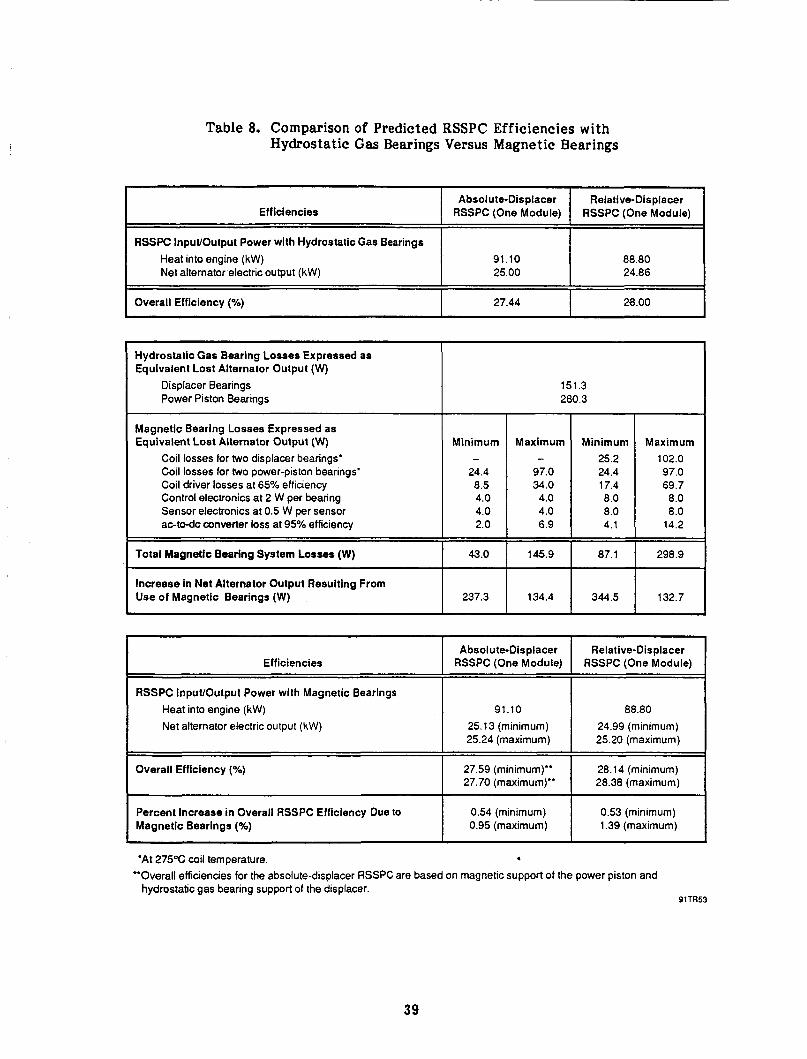
Table 8. Comparison of Predicted RSSPC Efficiencies with Hydrostatic Gas Bearings Versus Magnetic Bearings
Efficiencies
RSSPC InpuVOutput Power with Hydrostatic Gas Bearings Heat into engine (kW) Net alternator electric output (kW)
Absolute-Displacer Relative-Displacer RSSPC (One Module) RSSPC (One Module)
91.10 88.80 25.00 24.86
I 28.00 I 27.44 Overall Efficiency (%) I
Magnetic Bearing Losses Expressed as Equivalent Lost Alternator Output (W)
Coil losses for two displacer bearings.
Coil driver losses at 65% efficiency
aoto-dc converter loss at 95% efficiency
Coil losses for two power-piston bearings’
Control electronics at 2 W per bearing Sensor electronics at 0.5 W per sensor
Total Magnetic Bearing System Losses (W)
Hydrostatic Gas Bearing Losses Expressed as Equivalent Lost Alternator Output (W)
Displacer Bearings Power Piston Bearings
Minimum
24.4 8.5 4.0 4.0 2.0
43.0
-
RSSPC InpuIlOutput Power with Magnetic Bearings Heat into engine (kW) Net alternator electric output (kW)
Overall Efficiency (%)
Percent increase in Overall RSSPC Efficiency Due to Magnetic Bearings (%)
237.3 Increase in Net Alternator Output Resulting From Use of Magnetic Bearings (W)
91.10 25.13 (minimum) 25.24 (maximum)
27.59 (minimum)” 27.70 (maximum)”
0.54 (minimum) 0.95 (maximum)
151.3 280.3
Maximum
97.0 34.0 4.0 4.0 6.9
145.9
- 102.0
8.0 8.0 4.1 14.2
134.4 I 344.5 I 132.7
Efficiencies Absolute-Displacer
RSSPC (One Module)
1 I
1 Relative-Displacer RSSPC (One Module)
88.80 24.99 (minimurn) 25.20 (maximurn)
28.14 (minimum) ==i 28.38 (maximum)
0.53 (minimum) 1.39 (maximum)
*At 275°C coil temperature. 4
hydrostatic gas bearing support of the displacer. *Overall efficiencies for the absolute-displacer RSSPC are based on magnetic support of the power piston and
91TR53
39
6.0 DYNAMICS OF RSSPC ENGINE-BEARING SYSTEMS
An important aspect of applying magnetic bearings to the RSSPC is to ensure that the dynamics of the resulting engine-bearing system will be acceptable. System dynamics in the context discussed here pertain to both intrinsic system stability and to response of the magnetically supported displacer and/or power piston in the presence of internally and externally imposed excitations.
Extensive dynamics studies were performed for the SSPC under Contract NAS3-25463. These studies revealed that angular misalignments of the SSPC displacer and power pistons relative to their various clearance seals can produce significant dynamic radial gas forces at reciprocating frequency. Under conditions of low bearing stiffness, i t was shown that the piston-bearing system can be unstable as a consequence of these self- excited seal forces. Since magnetic bearings have significantly lower stiffness than gas bearings, and also require closed-loop feedback techniques to overcome their inherent instability characteristics, the question of overall RSSPC system stability received high priority in this study.
6.1 Undamped Open-Loop Natural Frequencies
The masses and inertias of the power piston and displacer for the candidate magnetic bearing RSSPC designs were listed in Table 6 of Section 5.0. Using these data, together with the corresponding center of gravity and bearing locations, the two undamped rigid- body natural frequencies were computed for the coupled translational and angular displacement modes of the power piston and displacer. These rigid-body natural frequencies are plotted as a function of bearing stiffness for the absolute- and relative- displacer RSSPCs in Figures 17 and 18, respectively. It is important to note that these rigid-body natural frequencies assume constant bearing stiffness and open-loop system configuration (Le., no feedback loops).
In a transverse 1-g gravitational field, the reciprocating motion of the center of gravity of the pistons will give rise to an exciting moment at the second harmonic of reciprocating frequency. Accordingly, i t is desirable that the two coupled rigid-body natural frequencies be well removed froms and preferably above, both the fundamental and second harmonic of the RSSPC operating frequency.
Figures 17 and 18 illustrate that the first natural frequency of the power piston for each configuration will be very close to the 70-Hz RSSPC operating frequency if the bearing stiffness is in the vicinity of 40,000 lbf/in. Furthermore, the coupled second natural frequency will be very close to the second harmonic of operating frequency. This implies that significant damping may be required to minimize rigid-body resonances for bearing stiffnesses in the range of 40,000 lbf/in. Potential sources of damping are gas f i lm damping from the piston gas spring clearance seal and electromagnetic damping from the magnetic bearings. However, Figures 17 and 18 indicate that it would be highly desirable for bearing stiffnesses to be in the range of 80,000 lbf/in., so that RSSPC operating frequency would be substantially below the first rigid-body natural frequency. In a qualitative sense, the more that open-loop natural frequencies can be increased above RSSPC operating frequency, the greater will be the likelihood of stable closed-loop operation. Again, it is emphasized that true dynamic response will be determined by the closed-loop dynamics of the magnetic bearing-piston system.
INTENTIONALLY BLANK 4 1
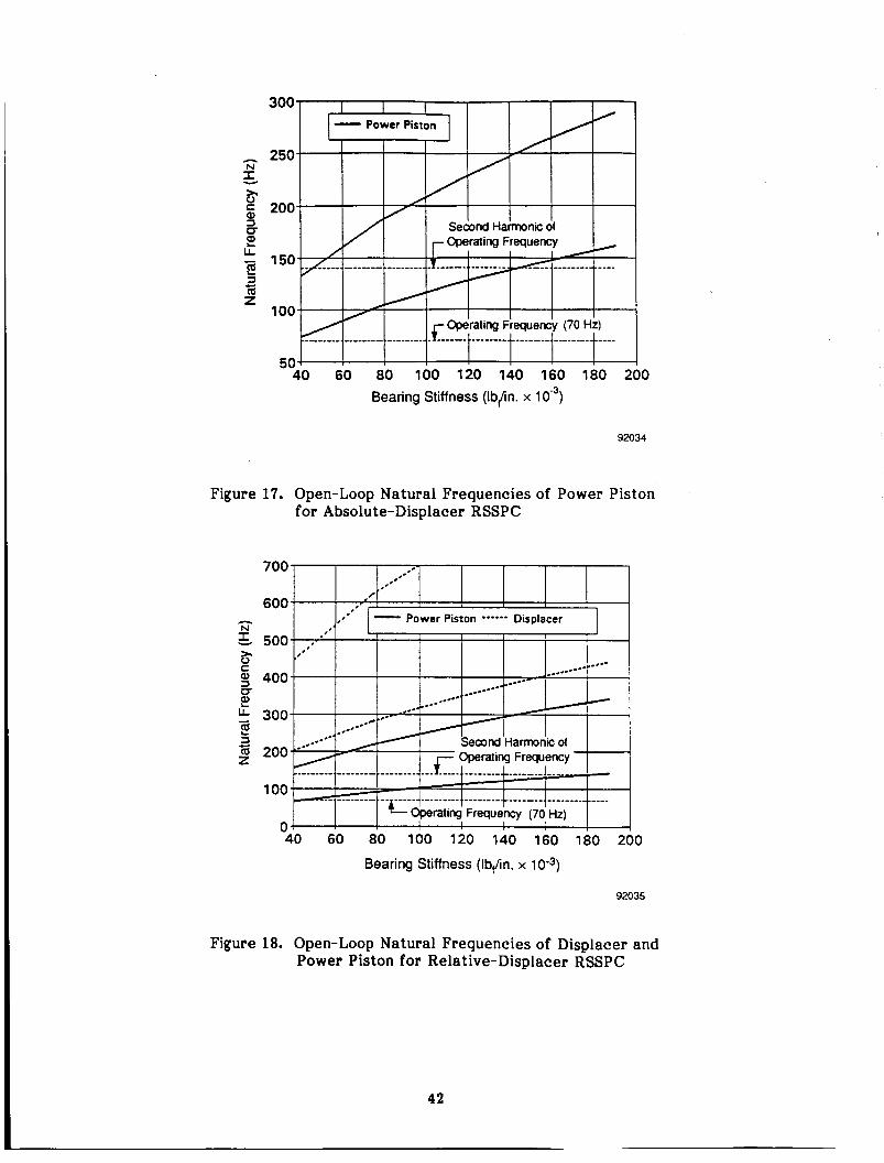
A N
3 )r 0 c Q, =I
L L
2 m z
- 2 c)
Figure
A N z- 2. 0 c Q, =I CT
LL 2
2 iij z
- 2
Figure
300
250
200
150
100
50 40 60 80 100 120 140 160 180 200
Bearing Stiffness (Ib/in. x lo”)
92034
17. Open-Loop Natural Frequencies of Power Piston for Absolute-Displacer RSSPC
40 60 80 100 120 140 160 180 200
Bearing Stiffness (Ib,/in. x 10”)
92035
18. Open-Loop Natural Frequencies of Displacer and Power Piston for Relative-Displacer RSSPC
42

Figure 18 also shows the coupled rigid-body natural frequencies for the displacer piston of the relative-displacer RSSPC. For bearing stiffnesses greater than 35,000 lb /in., it is
frequencies. This bodes well for closed-loop stability of the displacer. seen that even the second harmonic of RSSPC operating frequency is below bot f; natural
The hydrostatic gas bearings used in the RSSPC have predicted stiffnesses greater than 600,000 lbf/in. At these high stiffnesses, the 70-Hz RSSPC operating frequency falls well below all of the power piston and displacer natural frequencies. In addition, the hydrostatic bearings provide a large amount of damping. Accordingly, stable operation of both the RSSPC and the current CTPC h a s been predicted. Testing of the CTPC under the SSPC contract has so far confirmed these predictions.
6.2 RSSPC Dynamic Response
Under the SSPC program (NAS3-25463), existing MTI hydrostatic bearing and seal analysis codes were combined into a PC-based, time-stepping, graphics-output code to evaluate transient response and stability of the RSSPC under the influence of alternator, bearing, seal, and porting forces. This code accounts for both axial and circumferential flow components in the hydrostatic bearings and clearance seals, and allows for both transverse and angular rigid-body degrees of freedom. The code allows mid-stroke ports or grooves to be incorporated into seal regions, and accounts for time-varying boundary pressures at the ends of bearings and seals, as well as time-varying supply and exhaust pressures for ports.
Under the subject magnetic bearing program, this code was extended to allow modeling of magnetic bearings, including closed-loop proportional, integral, and derivative (PID) control of the bearings based on bearing position feedback. The magnetic bearing model itself includes the magnetic side-pull gradient of the bearings due to the dc bias current, plus a second-order differential equation representation of coil driver circuits (Le., power amplifiers) using ac control current feedback. I t was established early in the dynamics study that, without current feedback, the magnetic bearing systems would always be unstable because of the rather high inductance (long time constant) of the bearing coils. The current feedback coil-driver circuits have a transfer function of the following form:
where:
$(s)
Ki Tc i B i
= ratio of Laplace transform of current divided by Laplace transform of
= static gain of driver circuit (amp/volt) = characteristic time constant of circuit
= damping ratio of circuit = 1/2Qi
where: Qi = quality factor for circuit.
voltage for the ith bearing coil
43

Based on frequency response characterizations of coil driver (power amplifier) circuits developed by MTI, the following achievable values for the dynamics parameters of the coil driver transfer function were used for the bearing dynamics calculations:
2.04 (296) 1.96 (285) 0.58 (85)
= 0.00010 sec for power piston bearings = 0.00004 sec for displacer piston bearings
Tci
(these characteristic times correspond to characteristic frequencies of 1591 and 3979 Hz, respectively);
= 0.5 (Qi = 1.0). B i
The following two subsections describe the results of the RSSPC dynamic response calculations. Calculations were made over a range of seal clearances at the rated power condition of the RSSPC (25 kWe per engine module). Table 9 lists the pressure wave parameters used in the stability calculations for both the absolute- and relative- displacer RSSPCs. It should be noted that for the relative-displacer RSSPC, the power piston and displacer were analyzed as separate pistons, each having two coupled positional degrees of freedom. In actuality, these two pistons are dynamically coupled through the piston-to-displacer clearance seal. If further evaluation of the relative- displacer RSSPC is undertaken, the dynamics code should be upgraded to allow the coupled four-degree-of-freedom piston-displacer system to be modeled.
-12.9 -14.6 180.0
Table 9. Pressure Wave Parameters for Candidate RSSPC Configurations (Mean Pressure of 15.03 MPa (2180.0 psia))
Configuration
AbsoluteDisplacer RSSPC Compression Space Expansion Space Piston Gas Spring
Pressure
-72.9 -74.6 120.0
Relatlve-Displacer RSSPC Compression Space 1.92 (278) Expansion Space 1.83 (266) Piston Gas Spring Displacer Gas Spring 1.87 (272) -52.0
-67.6 69.1
' 113.0 -1 20.0
44
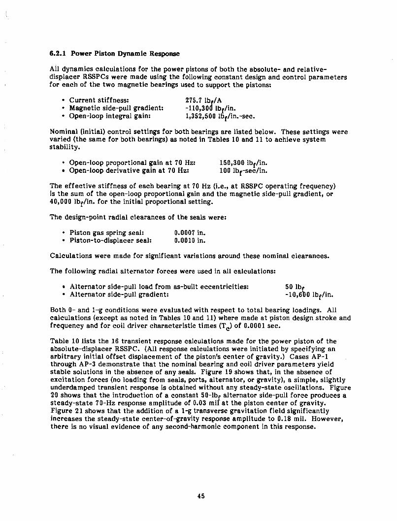
6.2.1 Power Piston Dynamic Response
All dynamics calculations for the power pistons of both the absolute- and relative- displacer RSSPCs were made using the following constant design and control parameters for each of the two magnetic bearings used to support the pistons:
Current st if fness: * Magnetic side-pull gradient:
Open-loop integral gain: 1,352,500 16, /in.-sec.
Nominal (initial) control settings for both bearings are listed below. These settings were varied (the same for both bearings) as noted in Tables 10 and 11 to achieve system stability.
* Open-loop proportional gain at 70 Hz: Open-loop derivative gain at 70 Hz:
150,300 lbf/in. 100 lbf-sec/in.
The effective stiffness of each bearing at 70 Hz (Le., at RSSPC operating frequency) is the sum of the open-loop proportional gain and the magnetic side-pull gradient, or 40,000 lbf/in. for the initial proportional setting.
The design-point radial clearances of the seals were:
* Piston gas spring seal: 0.0007 in. Piston-to-displacer seal: 0.0010 in.
Calculations were made for significant variations around these nominal clearances.
The following radial alternator forces were used in all calculations:
50 lbfI Alternator side-pull load from as-built eccentricities: Alternator side-pull gradient: -10,6 0 lbf/in.
Both 0- and 1% conditions were evaluated with respect to total bearing loadings. All calculations (except as noted in Tables 10 and 11) where made at piston design stroke and frequency and for coil driver characteristic times (T,) of 0.0001 sec.
Table 10 lists the 16 transient response calculations made for the power piston of the absolute-displacer RSSPC. (All response calculations were initiated by specifying an arbitrary initial offset displacement of the piston's center of gravity.) Cases AP-1 through AP-3 demonstrate that the nominal bearing and coil driver parameters yield stable solutions in the absence of any seals. Figure 19 shows that, in the absence of excitation forces (no loading from seals, ports, alternator, or gravity), a simple, slightly underdamped transient response is obtained without any steady-state oscillations. Figure 20 shows that the introduction of a constant 50-lb alternator side-pull force produces a
Figure 21 shows that the addition of a 1% transverse gravitation field significantly increases the steady-state center-of-gravity response amplitude to 0.18 mil. However, there is no visual evidence of any second-harmonic component in this response.
.
steady-state 70-Hz response amplitude of 0.03 mi f at the piston center of gravity.
45
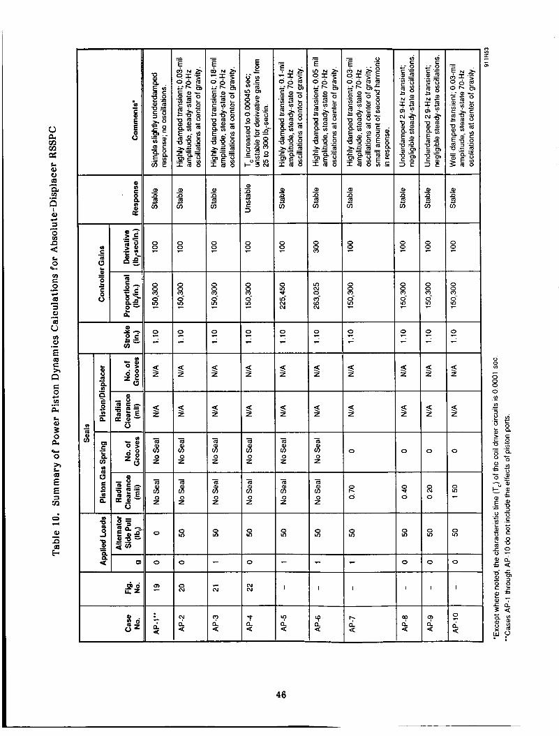
al a : C 3
0 s?
8 2- z
L 0 rw
2 0
a V a
m V
0 C
.- c,
d a
0
E
4
.-
ah
0 0 0 0
0 m m 2 z 7
0 0 8 8 2 2 0- 0
Q a- 0 g b, u)
z e
? z
? z
- i 0 z
z
? ? z z ? ? z z
? 5 z z
0 0
a q 0 -
0 0 m r o
0 0
e 0 c cn a k Q, 3 0 a 0 h
.e
rw
L
2 E a cn 0 7-l
a2 i3 3
? z / B
l- - - $ 8 0 0 z z
- m 2 0 z
- m 2 0 z
- - ; i 0 0 z z
0 0
2 x
0 m 0 In
0 In
0 m 0 m 0 m
- I
'9 a a -
- O l o 7 0
e ru I
c i s 4: I " '7 a a
P a a u! a a

9)
C
C 0
a .- e
u d
r; I-l
9)
F
2 O Z
8g 2 a
a % q (3
z
(I) - a
z x g 0
m
$ 6 i i Z
0 s!
a 8
h .- P cn
47

z 0.5 E
.- Proportional: 150,300 Ib/in.
I I I I Y
c
Derivative: 100 Ib,-sec/in. T,: 0.0001 sec
0.3 Gravity Loading: 0 g c Alternator Loading: 0 Ib, C a
0 c m h - 0.1
Piston Gas Spring Seal: None
0
C a
0
c
- n 0 2 4 6 8 10 12 14 16 18 ; -0.1
Piston Reciprocation Cycles at 70 Hz
92037 File: AP-1 .WQ1
Figure 19. Stable Power Piston Response for Absolute-Displacer RSSPC with No Loading from Seals, Ports, Alternator, or Gravity
e .- E v
% > c .- E (3 v- 0
48
v- 0
0.7
0.6
0.5
0.4
0.3
0.2
Alternator Loading: 50 Ib, Piston Stroke: 1.10 in.
Piston Gas Spring Seal: None
~-
c c 0.i t! - 2 0 Et a -0.1
a
0 5 10 15 20 25
Piston Reciprocation Cycles at 70 Hz
92038 File: AP-2.WQ1
Figure 20. Stable Power Piston Response for Absolute-Displacer RSSPC with Alternator Loading Only

h .- E Y
> > c .-
6 .c 0
t c c s c 0 v) c.
ii
1.41 1 I I I 1
Piston Gas Spring Seal: None 1.2 Derivative: 100 b,-sec/in.
1.0 '
0.8
0.6 I I
Gravity Loading: 1 g Alternator Loading: 50 lb, Piston Stroke: 1.10 in.
I
0 5 10 15 20 25
Piston Reciprocation Cycles at 70 hz 92043 File: AP-3.WQ1
Figure 21. Stable Power Piston Response for Absolute-Displacer RSSPC with Alternator Plus Gravity Loading
Case AP-4 and Figure 22 demonstrate that if the characteristic time of the coil driver circuits is increased from 0.0001 to 0.00045 sec, the system will become unstable. This instability persisted over the investigated range of controller derivative gain from 25 to 300 lbf-sec/in. The instability frequency was about 210 Hz, well above the open-loop undamped rigid-body natural frequencies of the piston for a bearing stiffness of 40,000 Ibf/in. This implies that the closed-loop magnetic bearing system effectively raises the system natural frequencies, but the closed-loop effective damping becomes negative a t a characteristic time of 0.00045 sec.
Cases AP-5 through AP-16 show the effects of increasing proportional and derivative gains and of including the piston gas spring seal with radial clearances from 0.3 to 1.5 mil. All of these cases produced stable responses for a characteristic time of 0.0001 sec for the coil driver circuits. As would be expected, increases in proportional gain resulted in smaller steady-state response amplitudes. Figure 23 shows that the response transient decays rapidly at the 0.7-mil design clearance of the gas spring seal. The final steady- state response of Figure 23 clearly shows a second-harmonic component of RSSPC operating frequency due to the l-g gravitational field assumed for this calculation. Figure 24 shows that the response exhibits an underdamped, 3.4-Hz transient waveform for small gas spring seal clearances. The reason for the low frequency of the transient is not clear at this time.
49
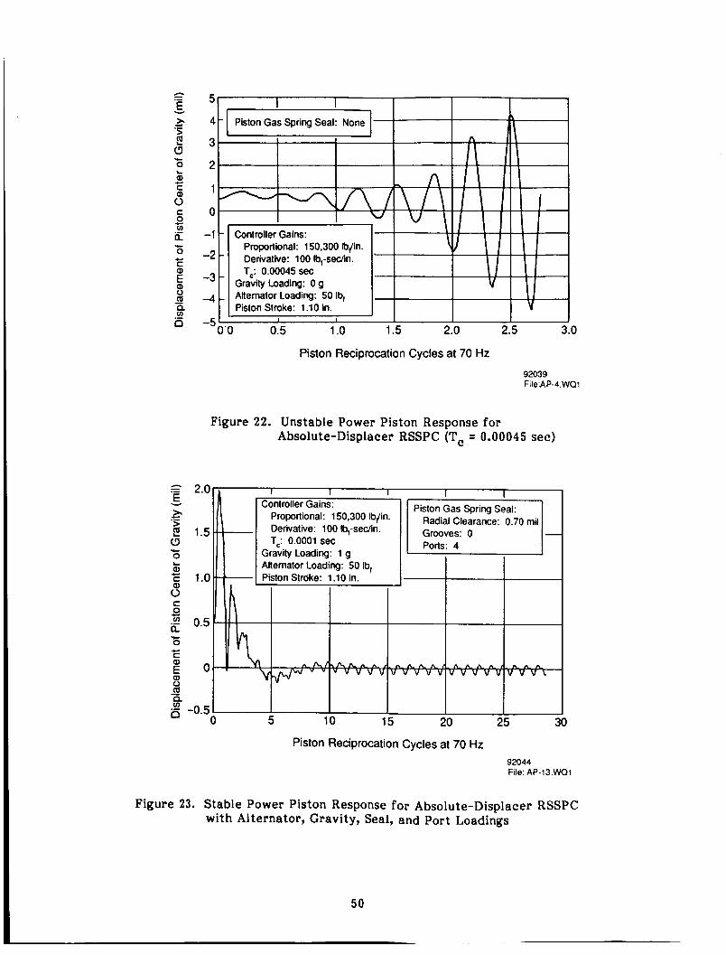
e .- E v
c .- > s .c 0
ti c C s C 0 v) c
ii L. 0
C *
0)
- : s is
h .- E v
.- 2? >
$ c 0
Q)
c L
c
3
5 -
4 .
3 .
2 .
1 '
0 .
-1
-2
-3
4
-5
'
(
I I
n v \
Controller Gains: Proportional: 150,300 Ibjin. Derivative: 100 Ib,-sec/in. T,: 0.00045 sec
Gravity Loading: 0 g Allemator Loading: 50 Ib, Piston Stroke: 1.10 in.
1'0 0.5 1 .o 1.5 2 0 2.5 3.0
Piston Reciprocation Cycles at 70 Hz 92039 File:AP-4.WO1
Figure 22. Unstable Power Piston Response for Absolute-Displacer RSSPC (Tc = 0.00045 sec )
2.01, I I I I I I
Piston Reciprocation Cycles at 70 Hz 92044 File: AP-13.WOl
Figure 23. Stable Power Piston Response for Absolute-Displacer RSSPC with Alternator, Gravity, Seal, and Port Loadings
50

Piston Reciprocation Cycles at 70 Hz 92042 File: AP-12.WQ1
Figure 24. Stable Power Piston Response for Absolute-Displacer RSSPC with Alternator, Seal, and Port Loadings (No Gravity Load)
Table 11 lists the 94 calculations made for the power piston dynamics of the relative- displacer RSSPC. Cases RP-1 through RP-3 demonstrate similar characteristics as discussed above for the piston of the absolute-displacer RSSPC. However, this power piston has less stability margin. This is demonstrated by Case RP-3a where, in the absence of seals, the system becomes unstable at a characteristic time of 0.00034 sec. Investigation of this case showed that the onset of instability was strongly affected by piston mass. When piston mass was increased from 31.8 to 47.6 lb (this being the mass of the power piston for the absolute-displacer RSSPC), the onset 07 instability occurred a t a characteristic time of 0.00042 sec, almost the same as for the absolute-displacer piston. However, the same percentage change in moment of inertia, both up and down, still resulted in the onset of instability occurring at a characteristic time of 0.00034 sec.
Cases RP-4 through RP-30f show the destabilizing effects of including first the piston gas spring seal and then the piston-to-displacer seal. The most stable set of results wi th both seals included was obtained by incorporating two grooves in the piston-to-displacer seal and one groove in the piston gas spring seal.
Cases RP-31 through RP-56 show the destabilizing effect of introducing four 0.080-in.-diameter mid-stroke ports in the piston gas spring seal. To obtain stability over the fu l l range of variation in seal clearances, it was necessary to increase proportional gain of the bearing controller by 25%, which corresponds to increasing bearing stiffness to 77,575 lbf/in.
5 1
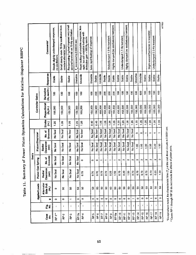
52
I
PIP
- m v)
P - - m Q v)
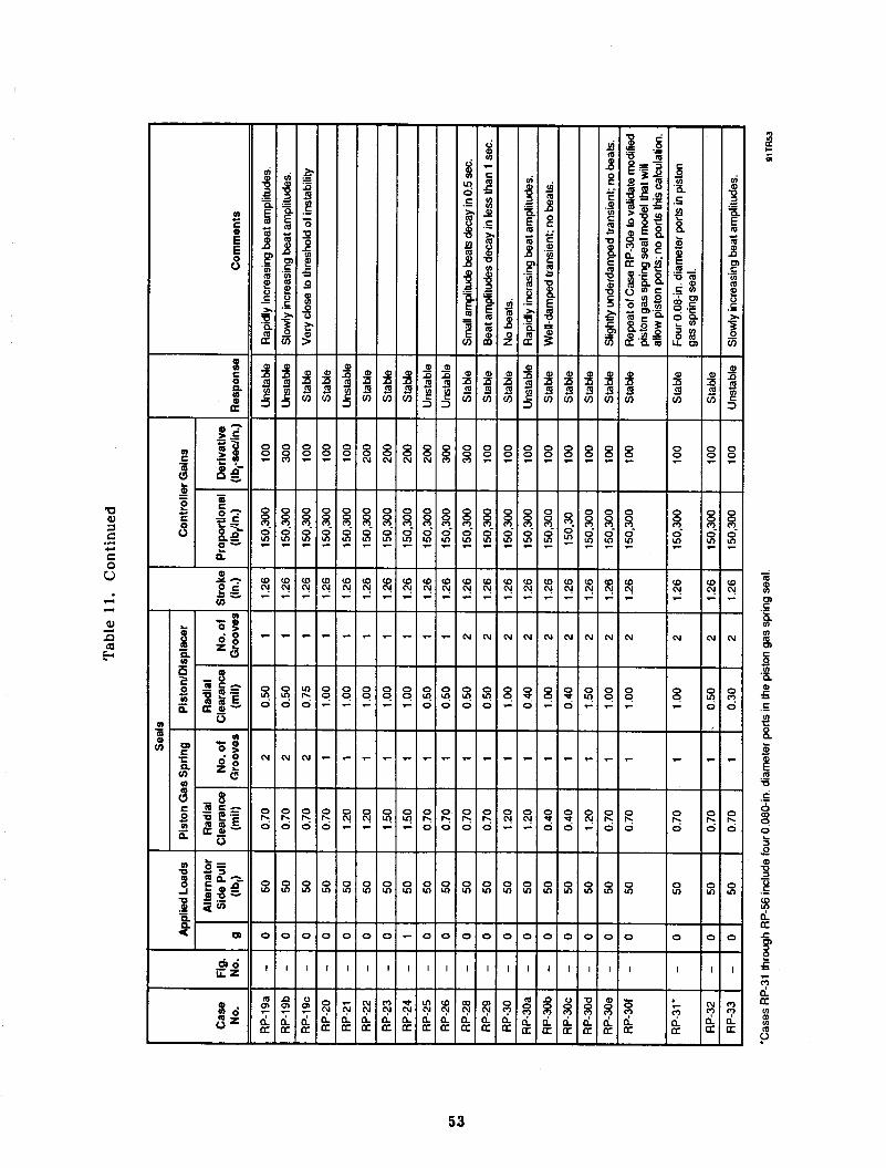
& 6 iiz
W N
(u
C .- Y &
0 0,
(u
0 0 9 9 e
e
0 0
0 0 k k
0 0 m m
0 0
I I
- - 0
3 a 3 a U U

54

4 5 - 0 rn
55

56
Cases RP-57 through RP-81 show the destabilizing e f fec t of introducing four 0.060-in.- d iameter mid-stroke ports in the piston-to-displacer seal (in addition t o the gas spring seal ports). To obtain stability over the full range of clearance variations in the seals, i t was necessary to increase proportional gain by 75% from the initial value. This corresponds to increasing bearing stiffness t o 152,725 lbf/in. Attempts t o stabil ize the piston at 50% increased proportional gain wi th various amounts of derivative gain were not successful for the combination of small gas spring seal clearance and nominal-to- increasing piston-to-displacer seal clearance. Figures 25, 26, and 27 show the computed responses at the piston center of gravity for Cases RP-73, RP-74, and RP-75a, respectively. Figure 25 is interesting in tha t it shows the instability frequency t o be about 4.7 Hz, as compared t o the much higher instability frequencies observed in the absence of all seals.
6.2.2 Displacer Dynamic Response
All response calculations for the displacer of the relative-displacer RSSPC were made using the following constant design and control parameters for both magnetic bearings:
Current stiffness: 35.14 lb /A 0 Magnetic side-pull gradient: -28,100 fbf/in.
6 13,200 lbf/in.-sec. Open-loop integral gain:
h .- 15 E v
> c .- ’ lo .c 0
c 5 5
s c s o
I -5
c
v)
h 5 0 a 0
C a
- c -10
E .- % 0 10 20 30 40 50 60 - 2 -15
n Piston Reciprocation Cycles at 70 Hz 92041 RP-73.WQ1
Figure 25. Unstable Power Piston Response for Relative-Displacer RSSPC with Seal and Port Loadings (Proportional Gain = 225,450 lbf/in.)

Piston Reciprocation Cycles at 70 Hz 92040 R P-74. WQ 1
Figure 26. Stable Power Piston Response for Relative-Displacer RSSPC with Seal and Port Loadings (Proportional Gain = 263,025 lbf/in.)
= 0.4 v
h > roportional: 263,025 Ib,/in. 2 Derivative: 100 Ib,-sedin. 2 0.2 Bearing Loads: 1 0
c .-
k) c C s c v) B O h L a
a 0 t a,
a 0
- -0.2 c
E
a 0 10 20 30 40 50 60 B 2 4 . 4
Piston Reciprocation Cycles at 70 Hz 92046 RP-75A.WQ1
Figure 27. Stable Power Piston Response for Relative-Displacer RSSPC with Seal, Port, and Gravity Loadings
57
Nominal (initial) control settings for both bearings are listed below. These settings were varied (the same for both bearings) as noted in Table 12 to achieve system stability.
Open-loop proportional gain at 70 Hz: Open-loop derivative gain at 70 Hz:
68,100 lbf/in. 100 lbf-sec/in.
The effective stiffness of each bearing at 70 Hz (Le., at RSSPC operating frequency) is the sum of the open-loop proportional gain and the magnetic side-pull gradient, or 40,000 lbf/in. for the initial proportional setting.
The design-point radial clearances of the seals were:
Expansion-to-compression-space seal: 0.002 in. Piston-to-displacer seal: 0.001 in.
Both 0- and l-g bearing loadings were evaluated. All calculations were done at displacer design stroke and frequency and for coil drive circuit characteristic times (T,) of 0.00004 sec (except as noted).
Table 12 lists the 54 calculations made for the displacer dynamics. Cases RD-1 and RD-2 demonstrate that the nominal bearing and coil driver parameters yield stable solutions in the absence of any seals. However, as demonstrated by Case RD-3, the system will go unstable if the characteristic time of the driver circuits is increased from 0.00004 to 0.00006 sec. Or, as Case RD-6 demonstrates, the system again becomes unstable if open-loop proportional gain is increased by 50%. Cases RD-7 through RD-36 show that the progressive inclusion of the expansion-to-compression-space seal and the piston-to-displacer seal results in increasing tendency to be unstable. It is necessary to introduce two grooves in the compression-to-expansion-space seal and one groove in the piston-to-displacer seal to achieve stable solutions at reasonable proportional gains.
Cases RD-37 through RD-52 include the effect of four mid-stroke ports in the piston-to- displacer seal. Because of the necessity of incorporating a groove in this seal, the seal length was increased from two inches (as shown earlier in Figure 12) to three inches. Such an increase in length appears achievable. It is seen that at least two combinations of proportional and derivative gains gave stable results over a wide range of seal clearance variation. Cases RD-50 through 52 confirm that two grooves are needed in the expansion-to-compression-space seal to maintain stability. Figures 28 and 29 show the computed responses at the displacer center of gravity for Cases RD-49 and RD-50, respectively. The instability response shown in Figure 29 is interesting in that two frequencies are evident: one at 35 Hz (one-half operating frequency) and one at 105 Hz.
6.2.3 Conclusions on RSSPC Dynamics
The most apparent result from this investigation is that stable operation of the RSSPC on magnetic bearings cannot be taken for granted. The second most apparent result is that considerably more investigation is needed to fully understand the stability and instability characteristics of this type of machinery. It is clearly a complex dynamics situation with a number of possible significant parameters.
58

U
cb6 iiz
0 0 0 2 5 8-
Q a - 5
8
-
0 0
5 - 7 F
- m 8 P
a 0) a a 9
v)
0 - 8
0 0
0 2 8 - 5
z Q - -
1 I 2 B - I m 8 P P
- - 8 8
P P v) v)
I
v ) v ) + 5 8 -
a E E
0'
59

a - a o >
a z 6 ;
6ad G Z
-r
C W VI C .-
b 8 U
5 e W z -
3 2 v)
-
0 m
- 0 0 cu
60

0 ?
- 0 8 ci N -
0 0 ? ?
I Q -.
- 0 9
N
0
3.
61

h .- 1.2 E
> 1.0 E (3 z 0.8
v
2. c .-
L al c c 3 0.6 L a, - 8 0.4 a
0.2 VI
0 c L
$ 0
I I Controller Gains:
Proportional: 68.100 Ibjin. ,
' y ~ v v v y v v v v v v v v v v v v v v v Y Y Y r al 0 a -
5 10 15 20 25 30 2 -0.20 ii
Displacer Reciprocation Cycles at 70 Hz
92045 RD-49.WQl
Figure 28. Stable Displacer Response for Relative-Displacer RSSPC with Seal, Port, and Gravity Loadings (Two Grooves in Expansion-to-Compression-Space Seal)
= .- 1.0 E v
2. > c. .- E 0.5 (3 .c 0 L al E O 3 L a,
a fn
- 8 -0.5
B .c 0
c al
c -1.0
5 0
a fn
- a -1.5
B 0 1 2 3 4 5 6
Displacer Reciprocation Cycles
7 8
at 70 Hz
9 10
92036 RD-50. WQ 1
Figure 29. Unstable Displacer Response for Relative-Displacer RSSPC with Seal and Port Loadings (One Groove in Expansion-to-Compression-Space Seal)
62

Taken a t face value, the results of the dynamics calculations presented herein indicate that:
Stable RSSPC magnetic bearing configurations are feasible With optimum PID controller gains, steady-state dynamic amplitudes of the displacer and power piston should not exceed 2.54 pm (0.1 mil) under zero-g transverse loading, or 5.08 p m (0.2 mil) under l-g transverse loading
0 In the case of the relative-displacer RSSPC, grooving of all clearance seals appears to be essential to achieve system stability The design with the most stability margin appears to be the power piston for the absolute-displacer RSSPC Dynamic response analysis of the complete closed-loop piston-bearing system is essential and must include all significant exciting mechanisms and system degrees of freedom. Simplified, open-loop dynamic analysis will not suffice for design of RSSPC magnetic bearing systems.
63
7.0 DISPLACEMENT SENSORS FOR MAGNETIC BEAHINGS
For active magnetic journal bearings, the radial location of the bearing within some reference clearance space must be continuously measured and transmitted to the bearing controller. In the case of the RSSPC, the tlbearingl' is either the displacer or the power piston. The reference clearance space must be the clearance of one or more of the critical gas spring seals associated with each piston since these clearances will be several times smaller than the actual magnetic bearing clearances. Since nominal radial clearances in the various seals will be in the range of 17.8 to 25.4 urn (0.7 to 1.0 mil), and ambient temperature in the regions of the seals and position sensors will be about 540 K (512'F), accuracy and long-term stability of the position sensors becomes critically i mportan t.
7.1 Types of Sensors
Noncontacting measurement of piston location can be performed by sensors that use electric fields, magnetic fields, or reflected radiation (e.g., light) to sense location. Commercial systems using all three of these approaches are available, but each has its advantages and disadvantages. Very few, if any, off-the-shelf systems can meet the combined high-temperature and long-term stability requirements of the RSSPC application.
Magnetic field measurements are performed using sensors referred to as either eddy current or inductive sensors, depending on whether a high frequency (greater than 100 kHz) or a low frequency (1 to 100 kHz) carrier signal is used. Eddy current sensors typically contain a miniature sensing coil located in the tip of the sensor that is excited by the carrier signal. Philips Laboratories of North American Philips Corporation, under contract to NASA-GSFC, has demonstrated 43,000 hr of engineering-model cryo-cooler operation on magnetic bearings using eddy-current bearing-position sensors.
One problem with magnetic field position sensors is that sensitivity variations will occur w i t h changes in piston temperature. Temperature changes cause variations of the resistance and permeability of the metal surface where the position measurement is performed. Eddy current sensors are sensitive to both surface resistance and permeability changes, while inductive sensors are sensitive only to permeability variations. However, these sensors are insensitive to the presence of materials such as grease or oil in the clearance between the sensor and the piston. This characteristic makes magnetic field sensors the best choice in applications where lubricating liquids are present. Probably the biggest difficulty in applying eddy current sensors to the RSSPC application would be designing a mechanically stable and long-life miniature sensing coil that would operate reliably at the 540 K ambient temperature level. In the Philips Laboratories' cryocooler application, the sensors operated at temperatures only slightly above room temperature.
In applications where lubricating liquids or surface contaminants do not exist, position measurement using electric field sensors, !.e., capacitance sensors, frequently tends to be the best choice. The capacitance sensor system is relatively insensitive to variations in surface material parameters and is totally insensitive to the presence of magnetic fields originating from the magnetic bearing coils. The capacitance sensors used by MTI do not contain electronic components within the sensor itself. The sensor is therefore more suitable for harsh environment applications because its simple metal and insulator construction is more rugged than the miniature sensing coils required in magnetic field sensors. The small size and adaptable geometry of the capacitance sensor allows it to be mounted within the radial thickness of cylinder walls, and hence it can be integrated into difficult-to-reach bearing and seal regions.
Reflected radiation sensors, specifically, reflected light sensors, have also been used as magnetic bearing sensors by Philips Laboratories in their second-generation prototype cryocooler development for NASA-GSFC. Initial development testing of this cryocooler has been successful, but long-term performance remains to be evaluated. A number of concerns have been expressed about this type of sensor, such as variation in sensitivity due to changes in surface reflectance and media opacity; stability characteristics under shock and vibration; sensitivity to contaminants in the gap between sensor and target; differential expansion between fiber-optic bundles and metallic sheaths; hermetic sealing of fiber-optic bundles; and size of the sensors.
7.2 Sensor Requirements
As mentioned previously, nominal radial clearances in the RSSPC seals will range from 17.8 to 25.4 pm (0.7 to 1.0 mil). These clearances establish the maximum allowable dynamic radial excursions of the displacer and power piston assemblies during steady- state RSSPC operation. Since the seals should not rub during steady-state operation, it was decided that maximum radial excursions should be limited to 25% of the design radial clearance of the seals. This would allow a reasonable margin €or accommodation of various factors that will determine actual geometry and mean eccentricities of the seals during RSSPC operation. These factors include differential thermal expansion distortions, long-term dc shifts in sensor calibrations, and accommodation of quasi- steady-state bearing loads such as might be imposed by station-keeping maneuvers.
Results of the dynamics calculations presented in Section 6.0 indicate that, under zero-g transverse loading, maximum radial excursions should be less than the 25% allowable criterion. Under l-g transverse loading, maximum radial excursions may exceed this criterion somewhat, but should not exceed 35% of design clearance.
Calculations of the 0-g steady-state dynamic bearing displacements due to seal and porting forces (and, in the case of the power piston, due also to alternator side-pull force) indicate displacement amplitudes of the order of 2.54 p m (100 pin). In trans- verse l-g fields the dynamic amplitudes are predicted to be larger, but may contain a small second harmonic of reciprocating frequency. Accordingly, the noise level of the bearing position sensors (including associated electronics) probably should not exceed 0.63 p m (25 uin.) in the 0 to 150-Hz frequency band.
When installed in the RSSPC bearing sensing configuration, long-term dc drift of the sensors (including associated electronics) should not exceed an amount equivalent to one- third of the nominal radial clearance of the RSSPC seals. For the piston gas spring seal, this amounts to a maximum allowable long-term drift equivalent to f6 .0 p m ( f236 pin.).
The least critical of the sensor requirements is the ac calibration accuracy of the sensors (with associated electronics). A reasonable requirement would be that the calibration factor not vary more than +3% over the operational range of the sensor.
The above sensor requirements (excluding electronics, but including signal leads contained within the RSSPC pressure shell) must be met over an ambient temperature range of 0 to 3OO0C in a helium environment at pressures from 75 to 150 bar. Min imum operational life of the sensors must be 60,000 hr, and the sensors must meet outgassing limits and vacuum degassing procedures that would be applied to the RSSPC itself.
66

7.3 Selected Sensor
MTI has extensive experience in magnetic field, electric field, and reflected light sensors for both reciprocating and rotating machinery and related bearing applications. For bearing applications where the bearing clearance does not contain contaminants, MTI feels that capacitance sensors are currently the best choice because of proven measure- ment stability and resolution. For development of the SSPC under contract NAS3-25463, MT1 has selected capacitance sensors for measurement of both dynamic displacer and power piston strokes and hydrostatic bearing clearances. Capacitance sensors were selected because of their proven high-temperature capabilities and their adaptability to fit into confined spaces. Figure 30 shows a photograph of one of the CTPC capacitance sensors used for measuring displacer stroke.
While fiber-optic sensors have the potential to meet the stringent RSSPC requirements, the technology is unproven at RSSPC operating conditions. Accordingly, capacitance sensors are the recommended sensors for RSSPC magnetic bearings a t this time.
sor wn from I Wall)
V92-97
Figure 30. One of Two Capacitance Sensors Used to Measure Reciprocating Stroke of the CTPC Displacer

Typical capacitance sensors used by MTI to measure bearing clearances have a 254-pm (10-mil) linear range and a calibration sensitivity (with associated electronics) of 1 V/mil. Noise level is typically 1/1000 of full-scale output, or 0.254 p m (10 pin.) for a 10-mil sensor. For the RSSPC application, it should be possible to use 5-mil sensors, and a noise level of 0.127 p m (5 pin.) would be attained. However, MTI has successfully operated large duct fans supported by magnetic bearings using 50-mil sensors wherein bearing orbits were controlled to less than 1.0-mil diameter. Based on this and other relevant experience, the sensitivity and noise characteristics of capacitance sensors are judged to be acceptable for RSSPC magnetic bearings.
For the current CTPC development under contract NAS3-25463, 10-mil capacitance sensors are being used to measure clearances of the hydrostatic bearings. The temperature sensitivity of these sensors has been measured up to 315OC using a specially designed calibration fixture. Figure 31 shows the change in output of one sensor as a function of temperature when a constant physical gap is measured. Data for two temperature cycles is shown, this being the first occasion that the sensor was subjected to elevated temperatures. The data shown in Figure 31 is typical of that obtained for six sensors tested. It is seen that an offset (shift) in room temperature output voltage occurred after the first temperature cycle, but that no detectable offset occurred after the second cycle. The total change in output voltage from room temperature to 315OC (a temperature change of 295OC) was 100 mV, or 1% of full-scale output.
The measured temperature sensitivity of these sensors is due to thermal expansion changes in the diameter of the sensors. A 1% change in sensor output would nominally be equivalent to a 0.1-mil change in sensor gap. If not compensated for, a 295OC change in temperature would produce a 0.1-mil shift in eccentricity of an actively controlled magnetic bearing. While such a shift could probably be tolerated in the RSSPC, several techniques can be used to compensate for inherent temperature sensitivity of the sensors.
1.63 I 0 -0
A V = 100 mV = 0.1 mil
m First Cycle = 1% of Full Scale . -
II 0 Second Cycle
i 1.59
1.57
3 1.55
6 1.53
- - -
u -0
3 Q +
0 100 200 300 400 500 600
Temperature (OF) 91901
Figure 31. Measured Output at Constant 254-pm (10-mil) Gap for CTPC Capacitance Sensor from 20 to 315OC Ambient Temperature

I t is well established that if the target being measured by a capacitance sensor is not electrically grounded with reference to the sensor's carrier signal frequency (typically about 16 kHz for capacitance sensors), the noise level of the sensor will increase signifi- cantly. Since the displacer and power piston of the RSSPC are completely floating bodies in a helium environment, there is no electrically conductive path to casing ground in the usual sense. To obtain common-mode noise rejection, the normal approach would be to use two capacitance sensors for each bearing axis. This would have the distinctly undesirable effect of doubling the required number of sensor signal leads and associated electronics. However, if the power piston and displacer are electrically coupled to casing ground through a capacitance that is 1000 or more times greater than the combined capacitance of the sensor gaps, the noise problem is greatly diminished and one sensor per axis can be used. For the RSSPC power piston, the gas spring seal, because of its small clearance and large surface area, provides more than 1000 times the capaci- tance of the sensor gaps. Similarly, the displacer gas spring and expansion-to- compression-space seals would provide sufficient capacitive coupling to ground for the displacer sensors in the relative-displacer RSSPC configuration. Thus, insofar as sensor noise is concerned, one capacitance sensor per bearing axis would be acceptable for the RSSPC.
There remains, however, still another consideration that can necessitate the use of two sensors per bearing axis, namely, differential thermal expansions between the sensor and target that cause a change in sensor gap. For single-sensor-per-axis systems, regardless of the type of sensor used, such changes would be interpreted by the magnetic bearing controller as a change in eccentricity of the bearing, when, in fact, there may be no change in true bearing eccentricity. If two sensors per axis are used and mounted 180° apart, both sensor temperature sensitivity effects and effects due to sensor gap changes resulting from uniform differential thermal expansions will be canceled.
In the design of the RSSPC, extreme care must be taken to minimize differential thermal expansions because of the magnitude of the temperature changes to which the pistons and bearings are subjected and the very small radial clearances that must be maintained in the seal regions. Recognizing that a temperature difference of only 10°F will produce a 34% change in radial clearance of the piston gas spring seal, and recognizing that the total change in temperature from room temperature to operating temperature will be about 500°F, it appears mandatory that two sensors per axis be used to cancel the majority of the differential expansion effects that are bound to occur.
Capacitance sensors represent the best demonstrated sensor technology currently available for the RSSPC magnetic bearings. However, the need to have two sensors (with associated electronics) per bearing axis to achieve cancellation of differential expansion effects is a major disadvantage from both a packaging and a reliability standpoint. This disadvantage would exist for any of the sensor types discussed here. If extensive operat- ion of the RSSPC (or CTPC) demonstrates that actual differential expansion effects are very small, or at least are repeatable and predictable as a function of operating condition, consideration can be given to using one sensor per bearing axis.
69

8.0 ELECTRONICS FOR MAGNETIC BEARINGS
Expert electronics design is key to the success of any active magnetic bearing applica- tion, particularly for space applications such as the RSSPC system where very long life (60,000 hr) at high reliability levels is essential. The fact that NASA-GSFC has recently contracted for long-life split-Stirling cryocoolers for the Earth Observing System (EOS) is an indication that 5O,OOO-hr, 0.98 reliable electronics is believed to be feasible in the near term (ref. 2). Although the EOS cryocooler will not use magnetic bearings, it is a reciprocating machine that requires very accurate and stable piston displacement sensors. These sensors are part of a closed-loop electronics drive and control system that controls the amplitude and phase of two reciprocating drive motors contained within each split-Stirling cryocooler. However, strictly on the basis of the quantity of electronics and sensors involved, the RSSPC magnetic bearing application represents a significantly greater reliability challenge than does the EOS application.
The following paragraphs describe some of the system and electronic circuitry configura- tions that can be used for control of active magnetic bearings. These descriptions by no means cover all of the many possible configurations. They do, however, represent configurations that MTI feels should be given strong consideration for the RSSPC application. I t was not possible within the funding resources available for this feasibility study to perform the detailed type of circuit design and development required to make electronic reliability predictions. Rather, electronic stability and reliability aspects are discussed in a qualitative sense, with reference where appropriate to space system developments with which MTI is familiar.
8.1 Closed-Loop System Configurations
Figure 32 illustrates a piston supported by two four-sector active magnetic bearings where each electromagnetic coil carries both the ac control and dc bias components of current. Only the X-2 bearing planes are shown. Identical system components would be required for the Y-Z bearing planes. The electronics associated with each capacitance position sensor are not shown; they may be assumed to reside within the position controller block.
The arrangement shown in Figure 32 requires an individual power amplifier for each magnetic bearing electromagnet. Each power amplifier provides both the dc bias and the ac control components of coil current. Accordingly, four position controllers, eight position sensors (including electronics), and eight power amplifiers are required for magnetic suspension of one reciprocating piston or displacer assembly. If the electronics blocks are located external to the RSSPC and a common return conductor is used for the electromagnets, a total of 25 hermetic electrical penetrations through the RSSPC pressure shell are required for each piston assembly. For a complete absolute-displacer RSSPC system (two power conversion modules with only the power pistons being magnetically supported), 50 pass-through penetrations would be required. For a complete relative-displacer RSSPC system, with both displacers and power pistons magnetically supported, 100 pass-through penetrations would be needed. These pass-throughs mus t hermetically seal 2200-psia pressure at an ambient temperature of about 25OOC.
If the control method shown in Figure 32 is used for three-sector bearings, a total of 23 hermetic pass-through connections would be required for each piston assembly. A complete absolute-displacer RSSPC system would thus have 46 pass-throughs, while a complete relative-displacer RSSPC would require 92 pass-throughs.

a r \ \ I
I J
/ I I I X: Electromagnet
Amplifier Amplifier
X; Power
1
X: Power Amdifier I
92076
Figure 32. Piston Supported by Four-Sector Active Magnetic Bearings with Common Coils for ac Control and dc Bias Currents (Only X-Z Plane Shown)
72

Figure 33 illustrates a piston supported by two four-sector active magnetic bearings where each electromagnet has two coils that separately carry the ac control and dc bias currents. Only the X-Z bearing planes are shown. Identical ac current controller and power amplifier components would be required for the Y-Z bearing planes. However, dc current for all of the dc bias coils would be supplied from one current source. The elec- tronics associated with each capacitance position sensor are not shown; they may be assumed to reside within the position controller block.
dc Bias Supply
-
t x Reciprocating
- Y-Axis - - ' Bias Coils +
Z
92075
Figure 33. Piston Supported by Four-Sector Active Magnetic Bearings with Separate Coils for ac Control and dc Bias Currents (Only X-Z Plane Shown)
73
The arrangement shown in Figure 33 requires one ac power amplifier for each magnetic bearing axis. Each power amplifier provides only ac control current to two series- connected, diametrically opposed and oppositely wound electromagnetic coils. All of the dc coils for both bearings are connected in series and carry a common value of dc bias current. Individual control of the dc bias in each electromagnet is not possible with this arrangement. This arrangement requires four position controllers, eight position sensors (including electronics), four power amplifiers, and one dc current source for magnetic suspension of one reciprocating piston or displacer assembly. If the electronics blocks are located external to the RSSPC and a common return conductor is used for both the dc bias coils and the four pairs of ac coils, a total of 22 hermetic electrical penetrations through the RSSPC pressure shell are required for each piston assembly. This is three less pass-throughs than are required for the configuration shown in Figure 32. For a complete absolute-displacer RSSPC system, 44 pass-throughs would be required, while for a complete relative-displacer RSSPC, 88 pass-throughs would be needed.
The trade-offs between the arrangements shown in Figures 32 and 33 do not lead to an obvious winner. In return for fewer pass-throughs and reduced electronics, the bearings shown in Figure 33 have a more complex mechanical design in that two coils must be packaged per electromagnet. (The arrangement of Figure 33 cannot be used with three- sector bearings). Regardless of the arrangement selected, a large number of hermetic pass-throughs will be required for a complete RSSPC system. This certainly provides an incentive for packaging the bearing electronics inside the RSSPC pressure shell. However, internal packaging would probably require four low-temperature coolant fluid penetrations through the RSSPC pressure shell to provide cooling to the electronics packages. Furthermore, the electronics packages would not be available for servicing or replacement. Extensive design and reliability assessments would be required to establish whether internal electronics packaging would be both feasible and desirable.
8.2 Bearing Control and Power Electronics
Figure 34 depicts a typical control loop for one of the two axes of an active magnetic bearing in both block diagram form and transfer function form. The loop transfer function is a series of component transfer functions multiplied together. As shown on the figure, these include the displacement sensor filters (sensor conditioner), the PID circuit (PID controller), the phase compensation network (phase-lead filter), and the power amplifiers and inductances. Each component comprising a single control transfer function is a first-order, a second-order, or an even higher-order filter. For a system with two radial magnetic journal bearings (with two axes of control per bearing), there will be at least 24 state variables just for the bearings.
The power amplifier forms the interface between the control electronics compensation circuitry and the magnetic elements of the bearing. It supplies bias current to provide the static force in the bearing and drives the dynamic current that produces the bearing control force. Selection of the power amplifier is a critical aspect of the control elec- tronics design because i t must supply bearing power without compromising the stability of the bearing feedback control system. It must also operate in a stable manner (supplying current into the high inductance, low resistance coil load) and have a low transfer function phase shift over the operating frequency range.
74

Measured Disolacement Y.
Block Diagram - Power
I . , Four Capaatance Sensors
Amplifier
Dynamic Force
i
Power Amplifiers and Inductances
Transfer Function Form
Y, =
G, =
G, =
GI =
G, =
Magnetic Bearing Center
y, Displacement
I Electromagners
Measured Displacement KI = Currentconstant
Sensor Filter Transfer Function K, = Mechanicalconstant
PID Circuit Transfer Function lb,.b3 I Bias Currents
Phase Compensation Transfer Function i = Dynamic Currents
Power Amplifier Transfer Function F, = Bearing Force 92074
Figure 34. Typical Magnetic Bearing Control Loop
75
The power amplifier was selected after the preliminary bearing design was completed and the parameters of the bearing were defined. The bearing parameter values used in the amplifier selection process were bias current, dynamic coil current, frequency range of the dynamic current, and bearing coil inductance, resistance, and back elec tro- motive force (EMF). These parameters define the power amplifier current and voltage ratings needed to drive the required current into the magnetic coil over the frequency range of interest.
The power amplifier was selected based on the following values of the bearing parameters:
Bias current: Ib = 1 A (power piston) and 2 A (displacer) Dynamic coil current: I = 0.3 A (power piston) and 1.85 A (displacer)
0 Reference frequency (RSSPC operating frequency): Fref = 70 Hz Bearing coil inductance: L = 0.039 H (power piston) and 0.0025 H (displacer) Bearing coil resistance: R = 3.02 ohm (power piston) and 0.765 ohm (displacer).
P
The bearing coil back-EMF was calculated based on the coil inductance, dynamic coil current, and RSSPC operating frequency. The maximum coil back-EMF that the power amplifier mus t overcome will occur when the highest peak current is driven into the coil at the highest required frequency. The voltage for this condition is:
The voltage drop across the coil resistance was calculated on the basis of the bias current and the peak dynamic current. On this basis, the bearing coil resistance voltage is:
= R*(I t I ). '1 R b P The resulting values are:
Bearing coil back-EMF voltage: Vback = 5 V (power piston) and 2 V (displacer) Bearing coil resistance voltage: VIR =3.93 V (power piston) and 2.95 V (displacer).
The vector sum of the back-EMF and coil resistance voltage maximum values is about 6.35 V for the power piston and 3.56 V for the displacer. These voltages were summed vectorially because of the quadrature nature of the inductive and resistive impedances. A 24 V dc power supply provides ample margin for the power amplifier for both pistons.
Using the bearing coil parameters, a power amplifier with the following operational capability was selected for both pistons:
6 A of maximum continuous current 20 V of maximum output voltage ( w i t h a 24-V power supply) 500-Hz amplifier bandwidth (with inductive load).
The power amplifier circuit capability has a factor of 4.5 margin above the power piston current requirement, a 1.5 margin above the displacer current requirement, and a voltage capability that is more than a factor of 3 above the voltage requirements. These margins are required to achieve reliable operation in the bearing system without saturation and to accommodate any increases of the bias current and dynamic current magnitudes that might be needed to produce the required RSSPC operation.
76
A pulse-width-modulating (PWM) type power amplifier with current drive output (a Model lOA8 manufactured by Advanced Motion Controls) was chosen to provide high efficiency operation and low phase shift for the bearing system. The PWM-type amplifier achieves a more efficient transfer of power from a dc power supply to the bearing coil by operating the amplifier transistors in a switching mode rather than a linear mode. The switching mode keeps the amplifier power loss, which is the highest loss in the control circuit, to a minimum value.
The current drive output configuration of the power amplifier produces an output current proportional to the input voltage signal amplitude independent of the amplifier load impedance. The load independence characteristics of the amplifier current drive allows high-frequency bearing control currents to be driven into each axis coil without the frequency limitations that would be produced by a voltage output amplifier driving current into the inductivehesistive load.
The power amplifier current drive working with the bearing coil inductance and resis- tance noted achieves a low-phase-shift frequency response capability that is greater than 20 times higher than that achievable with a voltage drive output amplifier.
8.3 Control Electronics System Packaging
The control electronics for two axes of one radial bearing controller would consist of the following components:
Two sets of sensor amplifiers, demodulators, and filters for the sensor electronics circuit Two PID controllers and filters for the control electronics circuit Four power amplifiers for the power amplifier circuit. f15 V dc power supply (sufficient for two journal bearings).
An assessment of the volume required for the control electronics was made based on the bearing sizes. This assessment, summarized below, focused on four main system subassemblies: the sensor electronics circuit, the control electronics circuit, the power amplifier circuit, and the power supply.
* Sensor Electronics Circuit. Figure 35 shows a sketch of the sensor circuitry for two axes of a bearing. The circuit board will be 4.6 x 4.2 x 0.4 in. and will include connectors for the four sensors, the circuit power, and the piston location signals. Two capacitance sensors will be used to determine the radial position of the piston for each bearing axis. Each sensor wi l l require a hybrid electronic circuit to generate the sensor sine wave excitation current, measure the ac sensor voltage, and produce an ac voltage proportional to the piston's radial position. Both of these hybrid circuits will be 1.7 x 0.9 x 0.2 in.
In addition to the two sensor interface circuits, a hybrid circuit that sums the two ac sensor signals and produces a dc signal proportional to the piston radial position is required for each bearing axis. This ac detection circuit will be 1.2 x 0.5 x 0.2 in. A small additional circuit board (not shown) will contain a sine wave generator circuit that will provide the ac carrier signal to the sensor electronic circuitry of all the displacer and PO er piston bearing axes. This generator circuit will have a volume of 1.04 in. 5
77
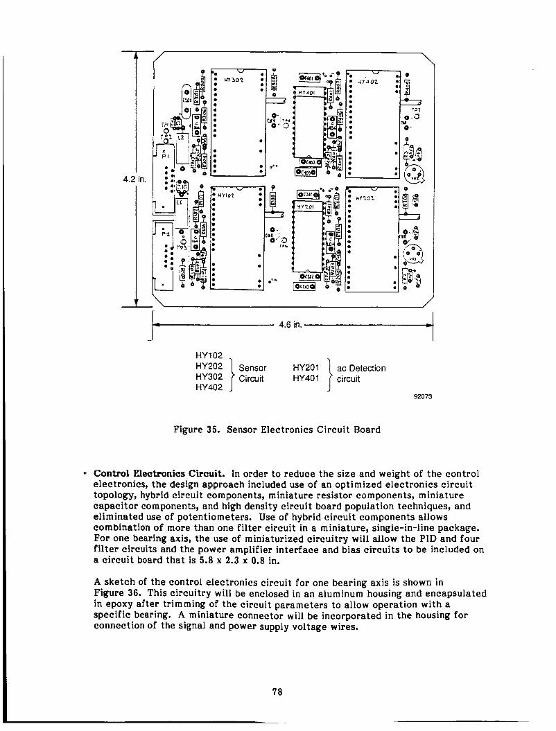
4.2 in.
0
/
4
- - 4.6 in.
92073
HY 102
HY402
Figure 35. Sensor Electronics Circuit Board
0 Control Electronics Circuit. In order to reduce the size and weight of the control electronics, the design approach included use of an optimized electronics circuit topology, hybrid circuit components, miniature resistor components, miniature capacitor components, and high density circuit board population techniques, and eliminated use of potentiometers. Use of hybrid circuit components allows combination of more than one filter circuit in a miniature, single-in-line package. For one bearing axis, the use of miniaturized circuitry will allow the PID and four filter circuits and the power amplifier interface and bias circuits to be included on a circuit board that is 5.8 x 2.3 x 0.8 in.
A sketch of the control electronics circuit for one bearing axis is shown in Figure 36. This circuitry will be enclosed in an aluminum housing and encapsulated in epoxy after trimming of the circuit parameters to allow operation with a specific bearing. A miniature connector will be incorporated in the housing for connection of t h e signal and power supply voltage wires.

2.3 in.
- 1
U 3
20 -
-1 ff U U
0
4 5.8 in. *
Summing u y i } ;;:;der and
"5A Compensation Power U7A } Amplifier "76 interface
#
Figure 36. Control Electronics Circuit Board
921 14(M)
Power Amplifier Circuit. The power amplifier for each bearing axis will be attached to a circuit board that is 6.0 x 3.0 x 0.8 in. A screw-type terminal strip will be included on the board for connection of power and signal wires. Threaded holes will be located on the amplifier top surface to allow attachment to a heat sink surface required to maintain the power amplifier temperature under a safe operating value. The maximum power dissipation per power amplifier has been estimated to be 10 W.
Inductive and capacitive filter components will be located on the amplifier circuit board to minimize the PWM frequency ac current from the battery and to reduce the PWM frequency signal voltage on he cable to the bearing coil. These compon- ents will have a volume of about 2 in.' A sketch of the power amplifier circuit is shown in Figure 37.
Power Supply. It is assumed that a 28 V dc power source is available and that a voltage converter circuit will be required to convert the 28 V supply voltage to the +15 V power for the sensor and compensation electronic circuitry. The current draw from the 28-V source for either the displacer or power piston control system has been estimated to be a maximum of 0.5 A.
Miniature dc-dc converters are available to perform the conversion from 28 to k15 V and to electrically isolate the circuit supplies from the source. A dc-dc con- verter circuit with a 1.5411. volume can supply the estimated 0.5 A maximum current required by the electronic circuitry for this system. Figure 38 shows a
3
79
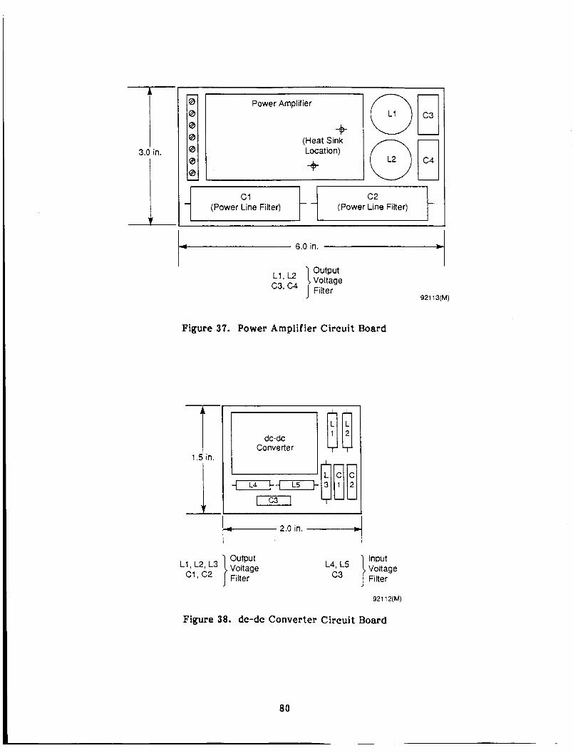
3.0 in.
4 6.0 in.
Power Amplifier
-+ (Heat Sink Locat ion) +
t c 2 (Power Line Filter) t i c1
(Power Line Fiiter) i 1 1 1 I
I
Figure 37.
output
Power Amplifier Circuit Board
1 Converter
output
Figure 38. dc-dc Converter
80
Input L 4 9 '5 Voltage
c3 ] Filter
Circuit Board
I
921 13(M)

sketch of the circuit board for the dc-dc converter. This board will be 2.0 x 1.5 x 0.5 in. and include filter capacitors to eliminate the bidirectional noise coupling between the source and the control electronics.
Table 13 presents the volume estimates for the control electronics system packaging. These estimates are based on a system with two magnetic jour a1 bearings that will be
estimated. Heat sinking of the power amplifiers to a large metal surface (the surface can be either electrically grounded or floating) will be required to remove thermal energy from the amplifier package and maintain its temperature at a safe operating value.
supplied power from a 28-V battery. A total volume of 118 in. 9 per piston assembly is
Table 13. Package Sizes for Control Electronics Circuitry (Per Piston Assembly)
Sensor electronics circuit
Sensor sine wave generator circuit
Control electronics circuit
Power Amplifier circuit
dc-dc converter circuit
~~
4.6 x 4.2 x 0.4 in. (7.7 in.3)
2.0 x 1.3 x 0.4 in. (1.04 in.3)
5.8 x 2.3 x 0.8 in. (1 0.7 in.3)
6.0 x 3.0 x 0.8 in. (1 4.4 in.3)
2.0 x 1.5 x 0.5 in. (1.5 in.3) ~~ ~
Total Estimated Volume: 118 in.3
'The above size estimates (length x width x height) are for a system where the power is provided from a 28-V dc battery.
81

9.0 CONCLUSIONS
Based on results reported in previous sections of this document, the following conclusions regarding application of magnetic bearings to the RSSPC may be stated:
Magnetic bearing support of the power piston is feasible for both the absolute- displacer and relative-displacer versions of the RSSPC.
Magnetic bearing support of the displacer appears feasible only for the relative- displacer RSSPC configuration. In the case of the absolute-displacer RSSPC, unacceptable changes to the regenerator, cooler, and pressure shell would be needed to incorporate magnetic bearings on the displacer. These changes would increase RSSPC size and mass and probably reduce RSSPC efficiency (although this latter supposition w a s not subjected to analytical confirmation). Use of magnetic bearings will improve overall RSSPC efficiency by 0.53 to 1.4% (0.14 to 0.38 efficiency points), depending on the amount of dc bias current required for the magnetic bearings. Efficiency improvement of the absolute- displacer RSSPC is expected to be closer to the lower end of this range since only the power piston can be magnetically supported.
Use of magnetic bearings will increase total mass of the absolute- and relative- displacer RSSPCs by approximately 13.9 and 24.7 kg, respectively. These increases represent 4.7 and 8.296, respectively, of the 6.0 kg/kWe specific mass goal for the RSSPC. Mass of the magnetic bearing electronics is not included in these estimates. The preferred type of magnetic bearing is the attraction-force active magnetic bearing. Selection of this bearing type is based on its high stiffness capabilities plus its technical maturity and application experience. The feasibility results reported herein are based on four-sector bearing designs using dc current biasing. It is believed that three-sector bearings would likewise be feasible. With three-sector bearings, the number of power amplifiers would be reduced from four to three per bearing with an attendant probable improvement in bearing system reliability. W i t h regard to overall RSSPC efficiency improvement, there does not appear to be a significant impetus to use permanent magnet biasing, rather than dc current biasing. However, further detailed design studies would be required to quantify this and to assess any other possible benefits of permanent magnet biasing. From a mechanical standpoint, design of the electromagnet's coils for the RSSPC magnetic bearings represents the greatest challenge because of the 3OO0C temperatures to which the coils will be subjected. In addition to developing a reliable means of mechanically packaging the coils into the bearing lamination stacks, a wire insulation system that will last for 60,000 hr mus t also be developed. The alternator of the RSSPC faces these same challenges. In this regard, current development work being performed by Pratt & Whitney Aircraft for the U.S. Air Force is highly pertinent since this work is directed a t magnetic bearing temperatures of 40OoC.
The preferred type of sensor for the active magnetic bearings is the capacitance sensor. Selection of this sensor is based on its demonstrated stability, acceptable noise level, and potential for long life at temperatures up to 30OoC. In addition, capacitance sensors can be readily adapted to f i t into very confined spaces, such as within the thickness of the RSSPC cylinder walls. The sensors should be located, where possible, for direct measurement of the operating seal clearances since these clearances will be much smaller than the actual magnetic bearing clearances.
*
0
*
*
a3
A disadvantage of magnetic bearings for the RSSPC is the large number of electrical sensor and coil leads that must hermetically penetrate the RSSPC pressure shell if the bearing's electronics are externally located. If four-sector bearings are used, the number of sensor and coil leads per piston will be either 25 or 22 depending on the bearing control system configuration. If three-sector bearings are used, the number of sensor and coil leads per piston will be 23. A hermetic seal against 2200-psia helium at an ambient temperature of approximately 250°C must be maintained around each of these electrical conductors. Internal routing and sealing of the numerous electrical leads within the RSSPC modules will also be a considerable design challenge.
Rigorous, nonlinear dynamic analysis of the complete closed-loop magnetic bearing system, including coupled dynamics of the power piston and displacer assemblies, is essential to successful application of magnetic bearings to the RSSPC. The dynamic analyses presented herein show that the various RSSPC clearance seals must be grooved to achieve bearing system stability. Additionally, current-feedback coil driver (power amplifier) circuits must be used to negate the destabilizing effect of the relatively long time constants of the bearing coils. The characteristic time for the second-order representation of these circuits must be of the order of 0.0001 sec for the power piston bear- ings and 0.00004 sec for the displacer bearings.
Results of the bearing design and control dynamics studies indicate that dynamic displacements of the magnetic bearings during normal steady-state RSSPC operation will not exceed 25% of the nominal gas spring seal clearances when operating in a 0-g environment. If the bearings are subjected to l-g transverse loadings, dynamic bearing displacements will not exceed 35% of nominal seal clearances. This degree of displacement control is believed to provide reasonable margin for such effects as distortions due to nonuniform differential thermal expansions; long-term dc drifts in sensor calibrations; and accommodation of quasi-steady-state bearing loads such as might be imposed by station-keeping maneuvers.
Magnetic bearings are mechanically and electrically complex and contain a large number of parts. Rigorous Failure Modes and Effects Analyses (FMEA) and reliability analyses will be required, once detailed bearing system designs are available, to determine the amount of redundancies needed to achieve specific long-term reliability levels. By comparison, the RSSPC hydrostatic gas bearing system has fewer mechanical parts and no electrical parts. The primary concern about the hydrostatic bearings, and one that is difficult to quantify, is the issue of orifice plugging due to debris. This issue is compounded by the fact that sliding contact of the bearings during start-up and shutdown will inherently generate wear debris. Magnetic bearings, by their very nature, are comparatively insensitive to debris. From a reliability standpoint, both types of bearings will need further extensive evaluation before relative long-term reliabilities (at temperature levels of 250 to 30OoC) can be established.
Response of magnetic bearings to externally imposed shock and vibration was not addressed in this study. With further extension, the bearing dynamics code described in Section 6.0 could be used to quantitatively evaluate this issue. Because of the small clearances required for the gas spring seals, there is considerable doubt as to whether magnetic bearings could maintain contact-free seal operation under directly imposed shocks. For this reason, the seals must be designed to provide mechanical-limit-stop capability for radial displacements of
*
0
*
84
the power piston and displacer assemblies. This means that the seal materials must be capable of surviving a large number of shock- and vibration-induced momentary contacts without degradation of RSSPC performance. This same requirement m u s t also be met by any gas bearing system. Extensive shock and vibration testing of gas bearings by MTI for the U.S. Navy and for NASA-LeRC has demonstrated that there are materials that can survive many such contacts at room temperature conditions. I t remains to determine the capabilities of these materials at RSSPC temperature levels. The estimated packaging volume for all of the external magnetic bearing system elect onics ne ded to support one piston assembly (Le., for two bearings) is 0.00193 m (118 in. ). 5 s
85

10.0 RECOMMENDATIONS
Magnetic bearings appear to offer a technically feasible alternative for the RSSPC power piston assembly and, in the case of the relative-displacer RSSPC, for the displacer assembly as well. Magnetic bearings overcome the major concerns of hydrostatic gas bearings, namely starthtop sliding and orif ice plugging. If sufficient resources are available, it would be technically worthwhile to demonstrate short-term high- temperature operation of magnetic bearings. I t would be relatively straightforward to design and build a magnetically supported power piston which would retrofit to the existing CTPC alternator and hot-engine components. Such a demonstration would provide a meaningful starting point for subsequent assessments of magnetic bearing system performance and reliability should the current gas bearing approach prove unsuitable.
While magnetic bearings appear technically feasible, the small increase in overall RSSPC efficiency that would result from using these bearings does not, by itself, justify the weight penalty or increased bearing system complexity. Magnetic bearings also raise a number of other concerns which cannot be quickly resolved. These pertain primarily to development of long-life coils for the bearings (a problem shared by the RSSPC alternator) and accurate evaluation of long-term stability and reliability at the elevated temperature of the RSSPC. Accordingly, MTI believes that the present hydrostatic bearings are still the system of choice.
If an alternative (backup) bearing system is desired, we recommend that hydrodynamic and squeeze-film gas bearings be evaluated in parallel with magnetic bearings for the RSSPC before considering any long-range commitment to magnetic bearings. MTI conducted a limited feasibility demonstration of hydrodynamic power piston operation during the SPDE program that preceded the current SSPC program. More recently, MTI has conceived a squeeze-film bearing design which may be suited to the RSSPC. All alternatives for this demanding and difficult bearing application should be carefully evaluated.

REFERENCES
1. "Final Review for NASA Prototype Model Refrigerator (Contract No. NASS- 26688).1t Presentation Document, Philips Laboratories, Briarcliff Manor, New York, August 1990.
2. "Statement of Work for Development and Test on an 80 K , Long Life, Low Vibration Cryocooler for Space Applications [Earth Observing System (EOS), Platform A1.l' NASA/Goddard Space Flight Center Request for Proposal 5-80694/239, November 1990: 1-3.

Form Approved REPORT DOCUMENTATION PAGE I OMB NO. 0704-0188
. AGENCY USE ONLY (Leave blank) 2. REPORT DATE
June 1992
I 'ublic reporting burden for this cnllectmn of informatmn IS estimated to average 1 hour per response, including the time for reviewing instructions searching existlng data sources. lathering and maintaining the data needed. and completing and reviewing the collection of information Send comments regarding this burden estimate or any other aspect of this ollectmn of inforrnatlon. including suggestmns for reducing this burden. to Washington Headquarters Servces. Directorate lor lnformation Operations and Reports 121 5 Jefferson )avis Highway, Sude 1204, Arlington. VA 22202-4302. and to the Office of Management and Budget, Papemork Reduction Project (07044188). Washington. DC 20503
3. REPORT TYPE AND DATES COVERED
Final Contractor Report . TITLE AND SUBTITLE
A Feasibility Assessment of Magnetic Bearings for Free-Piston Stirling Space Power Converters
wu-505-13-11 i. AUTHOR(S)
Dr. Peter W. Curwen, Dr. Dantam K. Rao, and Mr. Donald R. Wilson
5. FUNDING NUMBERS
a. PERFORMING ORGANIZATION '. PERFORMING ORGANIZATION NAME(S) AND ADDRESS(ES) REPORT NUMBER
I. SPONSORING/MONITORING AGENCY NAMES(S) AND ADDRESS(ES)
Mechanical Technology Incorporated 968 Albany-Shaker Road Latham, New York 121 10
10. SPONSORlNGIMONlTORING AGENCY REPORT NUMBER
E-7440 MT191TR53
12.. DISTRIBUTION/AVAILABlLlTY STATEMENT 12b. DISTRIBUTION CODE
National Aeronautics and Space Administration Lewis Research Center Cleveland, Ohio 44135-3191
Magnetic bcarings; Free-piston Stirling engines; Stirling space power systems
17. SECURITY CLASSIFICATION 18. SECURITY CLASS~F~CAT~ON 19. s ~ c u ~ n - y CLASSIFICATION OF REPORT OF THIS PAGE OF ABSTRACT
Unclassified Unclassified Unclassified
NASA CR-189 135
100
A05 16. PRICE CODE
20. LIMITATION OF ABSTRACT
I
11. SUPPLEMENTARY NOTES
Project Manager, David P. Fleming, Structures Division, NASA Lewis Research Center, Cleveland, Ohio 44135.
Unclassified -Unlimited Subject Category
I
13. ABSTRACT (Maximum 200 words)
This report describes a design and analysis sl'udy performed by Mechanical Technology Incorporated (MTI) under NASA Contract NASR-260hI. The objective o f the study was to assess the feasibility and efficacy of applying magnetic bearings to free-piston Stirling-cycle power conversion machinery of the type currently being evaluated for possible use i n long-term space missions. The study was performed for a SO-kWc Reference Stirling Space Power Converter (RSSPC) system consisting o f two 25-kWe free-piston Stirling engine modules. Two different versions o f thc RSSPC cnginc mod- ules have been defined under N A S A Contract NAS3-25463. These modules currently use hydrostatic gas bearings l o support the reciprocating displacer and power piston assemblies. Results o f this study show that active magnetic bearings o f the attractive electromagnetic type arc technically feasible for RSSPC application provided that wire insulation with 60,000-hr life capability at 300 "C can be dcvelopcd for the hearing coils. From a design integration standpoint, both versions o f the RSSPC were found to bc conceptually amenable to magnetic support o f the powcr piston assembly. However, only one version of the RSSPC was found to be amenable to magnetic support o f the displacer assembly. Unacceptable changes to thc hasic engine design would be required to incorporate magnetic displacer bearings into the second version. Complete magnetic suspension of the RSSPC can potentially increase overall efficiency o f the Stirling cycle power converter by 0.53 to 1.4 percent (0.15 to 0.4 cfficicncy points). Magnetic hcar- ings w i l l also overcome several operational concerns associated with hydrostatic gas bearing systems. However, these advanlagcs arc accompanied by a S to 8 percent incrcase i n specific mass of the RSSPC, depending on the RSSPC version employed. Additionally, magnetic bearings arc much more complex, both mechanically and particularly electronically, than hydrostatic hearings. Accordingly, long-term stability and rcliabilily rcprchcnt areas o f uncertainty for magnetic hcarings. Considerable development effort wi l l be required to establish the long-term suitability of thcsc hearings for Stirling space powcr applications.
14. SUBJECT TERMS 115. NUMBER OF PAGES
I I I Standard F o r m 298 (Rev. 2-89) Prescribed bv ANSI Std. 239-1 8
JSN 7540-01 -280-5500
298-1 02