department of aerospace engineering college of …magnetic suspensions and magnetic bearings. 3rd...
TRANSCRIPT
DEPARTMENT OF AEROSPACE ENGINEERING
DEPARTMENT OF MECHANICAL ENGINEERING
COLLEGE OF ENGINEERING & TECHNOLOGY
OLD DOMINION UNIVERSITY
NORFOLK, VIRGINIA 23529
/
/
LARGE ANGLE MAGNETIC SUSPENSION TEST FIXTURE
By
Dr. Colin P. Britcher, Principal Investigator
Dr. Jen-Kuang Huang, Co-Principal Investigator
Progress Report
For the period November 1, 1995 through May 1, 1996
Prepared for
National Aeronautics and Space Administration
Langley Research Center
Hampton, VA 23681-0001
Under
Research Grant NAG-I-1056
Nelson J. Groom, Technical Monitor
FDCD-Guidance and Control Branch
Submitted by the
Old Dominion University Research Foundation
P.O. Box 6369
Norfolk, VA 23508-0369
July 1996
https://ntrs.nasa.gov/search.jsp?R=19960041471 2020-07-29T01:12:18+00:00Z

SUMMARY
Good progressis being made in several major areas. These include eddy current
modelling and analysis, design optimization methods, wind tunnel Magnetic Suspension and
Balance Systems (MSBS), payload pointing and vibration isolation systems, and system
identification. In addition, another successful International Symposium has been completed,
with the Proceedings being printed at the time of writing.
These activities continue current work under this Grant and extend previous work on
magnetic suspension systems and devices in the Guidance and Control Branch and will permit
the demonstration of several new developments in the field of magnetic suspension technology.
REVIEW OF CURRENT AND ONGOING WORK
(i) Eddy current modelling. The ELEKTRA computer code has been used to calculate
forces, stored energy, field magnitude and phase, and power losses for magnetic suspension
(LAMSTF-Iike) and magnetic bearing (ASPS-like) configurations. Various problems have
been encountered and overcome, such that an analysis capability suitable for application to the
LGMSS project is steadily emerging. Validation and testing specific to the LGMSS application
will commence shortly. Some of this work has been published, with future publication possible.
(ii) Design optimization. An effort to apply state-of-the-art optimization methods and
computer codes to the magnetic suspension problem has begun. Initial analysis has
concentrated on small-gap, axisymmetric bearings. It has been shown that optimum designs
based on maximum force, minimum power, etc., are identifiable and are distinctly different from
each other. This effort will result in a publication at some point in the future. Analysis will
then proceed to the large-gap problem, which is more challenging, although some work has
already been accomplished (David Cox, LaRC).

(iii) Wind Tunnel Magnetic Suspension and Balance Systems. There appears to be
renewed interest in this application, both in general, and for a specific test objective, namely
ultra-high Reynold's number testing. A presentation relating to the latter has already been
made, with a copy attached as an Appendix to this report. A presentation relating to the former
is planned for the AIAA Aerospace Sciences meeting in January 1997. A copy of the abstract
is also attached as an Appendix.
(iv) Annular Suspension and Pointing System. Work continues at a low level,
following successful levitation in five degrees-of-freedom. The control software has been
"cleaned up" and some electrical upgrades made to reduce noise. A joint Proposal for future
work with LaRC and Boeing is under consideration and would result, if successful, in a
dramatic increase in effort in this area.
(v) System Identification. For identifying a dynamic system, operating under a
stochastic environment, projection filters, which were originally derived for deterministic
systems, are developed by using optimal estimation theory. This newly developed system
identification algorithm is successfully implemented at NASA Lanigey Research Center for
identification of unstable large-gap magnetic suspension systems. The results show that it can
be applied for dynamic systems with known or unknown feedback dynamics. The test data
processed can be either in the time domain or frequency domain. It is also _very effective in
controller design for nonlinear unstable systems and for direct Kalman filter gain estimation
without knowing noise covariances.
(vi) Symposium support. Support is being provided for the organization and execution
of the 3rd International Symposium on Magnetic Suspension Technology.
PROBLEM AREAS

The Federal furloughs significantly impacted the pace of work on-site at NASA. There
appears to have been little financial impact, although some doubts remain.

PRESENTATIONS and PUBLICATIONS
Britcher, C.P.; Groom, N.J.: Computational analysis of static and dynamic behaviour of
magnetic suspensions and magnetic bearings. 3rd International Symposium on Magnetic
Suspension Technology, Tallahassee, Florida, December 1995.
Neff, D.; Britcher, C.P.: Design and implementation of a digital controller for a vibration
isolation and vernier pointing system. 3rd International Symposium on Magnetic Suspension
Technology, Tallahassee, Florida, December 1995.
Britcher, C.P.: Application of Magnetic Suspension and Balance Systems to Ultra-High
Reynolds Number Facilitites. Workshop on Ultra-High Reynolds Number Flows. Brookhaven
National Laboratory, June 1996. (presented by Robert A. Kilgore).
Britcher, C.P.: Application of Magnetic Suspension Technology to Large Scale Facilities.
Accepted for presentation at AIAA Aerospace Sciences Meeting, Reno, NV, January 1997.
Cox, D.E.; Groom, N.J.; Hsiao, M.H.; Huang, J.K.:
magnetic suspension system. 3rd International
Technology, Tallahassee, Florida, December 1995.
Modling and identification of a large gap
Symposium on Magnetic Suspension
Hsiao, M.H.; Huang, J.K.; Cox, D.E.: Iterative LQG controller design through closed-loop
identification. ASME Journal of Dynamic Systems, Measurement and Control, June 1996.
Huang, J.K.; Hsiao, M.H.; Cox, D.E.: Indirect identification of linear stochastic systems with
known feedback dynmaics. AIAA Journal of Guidance, Control and Dynmaics, July/August
1996.
Lee, H.C.; Hsiao, M.H.; Huang, J.K.; Chen, C.W.: Identification of stochastic system and
controller via projection filters. ASME Journal of Vibration and Acoustics, August 1996.
Huang, JK.; Lee, H.C.; Scoen, M.P.; Hsiao, M.H.: State-space system identification from
closed-loop frequency response data. Accepted for AIAA Journal of Guidance, Control and
Dynamics.
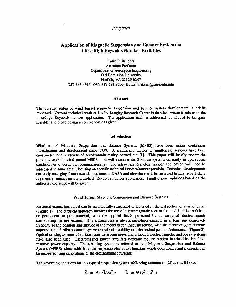
Preprint
Application of Magnetic Suspension and Balance Systems to
Ultra-High Reynolds Number Facilitites
Colin P. BritcherAssociate Professor
Department of Aerospace EngineeringOld Dominion UniversityNorfolk, VA 23529-0247
757-683-4916, FAX 757-683-3200, E-mail [email protected]
Abstract
The current status of wind tunnel magnetic suspension and balance system development is brieflyreviewed. Current technical work at NASA Langley Research Center is detailed, where it relates to theultra-high Reynolds number application. The application itself is addressed, concluded to be quitefeasible, and broad design recommendations given.
Introduction
Wind tunnel Magnetic Suspension and Balance Systems (MSBS) have been under continuousinvestigation and development since 1957. A significant number of small-scale systems have beenconstructed and a variety of aerodynamic testing carried out [1]. This paper will briefly review theprevious work in wind tunnel MSBSs and will examine the 8 known systems currently in operationalcondition or undergoing recommissioning. The ultra-high Reynolds number application will then beaddressed in some detail, focusing on specific technical issues wherever possible. Technical developmentscurrently emerging from research programs at NASA and elsewhere will be reviewed briefly, where thereis potential impact on the ultra-high Reynolds number application. Finally, some opinions based on theauthor's experience will be given.
Wind Tunnel Magnetic Suspension and Balance Systems
An aerodynamic test model can be magnetically suspended or levitated in the test section of a wind tunnel(Figure 1). The classical approach involves the use of a ferromagnetic core in the model, either soft ironor permanent magnet material, with the applied fields generated by an array of electromagnets
surrounding the test section. This arrangement is always open-loop unstable in at least one degree-of-freedom, so the position and attitude of the model is continuously sensed, wi.th the electromagnet currentsadjusted via a feedback control system to maintain stability and the desired position/orientation (Figure 2).Optical sensing systems of various types have been prevelant, although electromagnetic and X-ray systemshave also been used. Electromagnet power amplffers typically require modest bandwidths, but highreactive power capacity. The resulting system is referred to as a Magnetic Suspension and BalanceSystem (MSBS), since aside from the suspension/levitation function, whole-body forces and moments canbe recovered from calibrations of the electromagnet currents.
The governing equations for this typeof suspension system (following notation in [2]) are as follows •
I_¢__ V(I_.VB_) "r_ = ¥(MxB'o)

- where M represents the magnetization of the magnetic core in A/m, 13 the applied magnetic field in
Tesla, V is the volume of the magnetic core in m3, and the subscript o indicates that the field or field
gradient is evaluated at the centroid of the magnetic core. Now, following the detailed development
presented in reference 2, the effect of changes in relative orientation between the magnetic core and the
electromagnet array can be incorporated as follows :
F_ = V [Tml[aBl[Tm]" I_ T =V
Where a bar over a variable indicates magnetic core coordinates, [013] is a matrix of field gradients and
lTm] is the coordinate transformation matrix from electromagnet coordinates to suspended element
(magnetic core) coordinates. Study of the torque equation reveals that it is only possible to generate 2
components by this "compass needle" phenomena with a single magnetization direction. This gives rise
to the well-known "roll control" problem in wind tunnel MSBSs, where the magnetization direction has
usually been along the long axis of the magnetic core, in turn along the axis of the fuselage.
In wind tunnel applications, the primary motivation for MSBSs has been the elimination of the
aerodynamic interference arising from mechanical model support systems [3]. The fact that the
suspended model forms part of a feedback control system inherently permits predetermined motions of the
suspended model to be created rather easily. This suggests great potential for studies of unsteady
aerodynanic phenomena, although the potential has not been fully exploited at this time (see later
Section).
It should be noted that the configuration discussed above is not the only possibility. Inherently stable
configurations are feasible, such as by using a.c. applied fields, or by inclusion of diamagnetic materials in
various ways. Laboratory suspensions using these techniques have been demonstrated for many years [4],
but not in the wind tunnel application. A major disadvantage has been the difficulty of arranging
significant passive damping of unwanted motions. The feedback controlled approach relies on artificial
damping, whose value is limited principally by the control algorithm and the power supply capacity.
A Perspective on Ultra-High Reynolds Number Tunnels
So that the rest of this paper be set in proper context, the author's perspective on the ultra-high Reynolds
number tunnel development effort will now be presented.
Research has been underway for several years examining the possibility of constructing an ultra-high
Reynolds number "wind" tunnel, concentrating on the use of liquid or gaseous helium as the working
fluid. At one point, the tunnel was referred to by some researchers as the "infinite Reynolds number"
wind tunnel, since operation with superfluid helium was contemplated and a promise of effectively zero
viscosity of the working fluid was held out. Current work appears to be focused on slightly more modest
performance (finite Reynolds number!) but could still result in a facility with a Reynolds number
capability one order of magnitude higher than anything currently existing. With these more modest
objectives, the option of employing gaseous helium as the working fluid becomes quite viable, as has been
suggested many times over the years [5].
The engineering application is clearly to hydrodynamic studies of submersibles, with the particular item of
interest perhaps being wake-related signature reduction. Fundamental studies of high Reynolds number
turbulence are also attracting some interest. It has been assumed that an MSBS would be mandatory for
this type of facility, since a conventional support system would create severe problems by corruption of the
vehicle's wake. Application of MSBS technology to this problem was reviewed in the 1989 Workshop [6].

Current MSBS Activity Worldwide
NASA Langley Research Center 13-inch MSBS
This system, illustrated in Figure 3, is currently inactive, although remains in operational condition. It
comprises a low-speed wind tunnel, 5 uncooled copper electromagnets, 4 with iron cores, bipolar thyristor
power supplies, an optical model position sensing system with a minicomputer-based digital controller.
The system has been used for a variety of drag studies of axisymmetric and near-axisymmetric geometries,as well as support interference evaluations. Support interference increments of up to 200% have been
discovered, although this is hardly typical [7,8].
The ODU 6-inch MSBS
If this system were to be described as the ODU/NASA/MIT 6-inch system, then its history and identitywould be clear to all workers in the MSBS field. The electromagnet assembly and low-speed wind tunnel,
illustrated in Figure 4, from the original MIT "6-inch" MSBS [9,10] has found its way to Old Dominion
University, and partial recommissioning is currently in progress. A unique feature is the use of
electromagnetic position and attitude sensing. Here, the suspended model forms the core of a high
frequency variable differential transformer. It is planned to restore the system to full operation with new
power supplies and a digital control system.
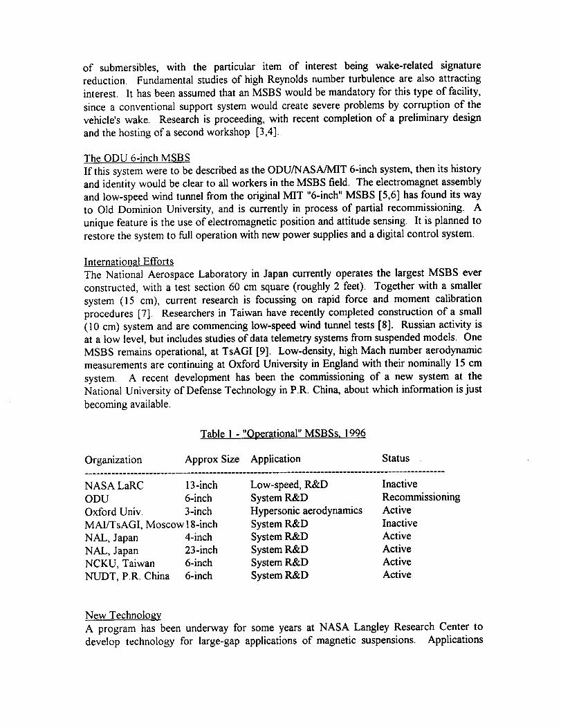
International Efforts
The National Aerospace Laboratory in Japan currently operates the largest MSBS ever constructed, with a
test section 60 cm square (roughly 2 feet). Together with a smaller system (15 cm), current research is
focusing on rapid force and moment calibration procedures [1 I]. Researchers in Taiwan have recently
completed construction of a small (10 cm) system and are commencing low-speed wind tunnel tests [12].Russian activity is at a low level, but includes studies of data telemetry systems from suspended models.
One MSBS remains operational, at MAI/TsAGI [13]. Low-density, high Mach number aerodynamic
measurements are continuing at Oxford University in England with their nominally 7.5 cm system [14].
A recent development has been the discovery of a new system at the National University of Defense
Technology in P.R. China, about which information is just becoming available.
Table 1 - "Operational" MSBSs, 1996
Organization Approx Size I Application Status
NASA LaRC 13-inch Low-speed drag, R&D Inactive
ODU 6-inch System R&D Recommissioning
Oxford Univ. 3-inch H_q_ersonic aerodynamics Active
MAI/TsAGI, Moscow 15-inch System R&D Inactive
NAL, Japan 4-inch System R&D Active
NAL, Japan 23-inch System R&D Active
NCKU, Taiwan 6-inch System R&D Active
NUDT, P.R. China 6-inch System R&D Active
New Technology
A program has been underway for some years at NASA Langley Research Center to develop technology
for large-gap applications of magnetic suspensions. Applications include, but are not limited to, wind
tunnel MSBSs, space payload pointing and vibration isolation systems, momentum storage and control
tSquare-root of wind tunnel test section cross-sectional area

devices, maglev trains and electromagnetic launch systems. Emphasis has been placed on the
development of formalized dynamic models and the application of modern controller design techniques.
Two small laboratory scale levitation systems have been constructed, with air-gaps between suspended
element and electromagnets of 10 cm [15,16]. The first system is referred to as the Large-Angle Magnetic
Suspension Test Fixture (LAMSTF) and is capable of 360-degree rotation of the levitated model about a
vertical axis (Figure 5). Levitation here implies the use of magnetic forces of repulsion from below the
test object, rather than the more traditional approach of attractive forces from above, or some combination.
The second system, currently unnamed, utilizes a pair of concentric coils carrying steady currents, to
provide a background force opposing gravity. An important novel feature is the use of a transversely
magnetized permanent magnet core in the cylindrical suspended element. The magnetization direction is
vertical is this application. This configuration, illustrated in Figure 6, provides full six degree-of-freedom
control capability with passive stability in vertical translation and two rotations. The third rotation (about
the vertical axis) is neutrally stable, and the remaining two translations (in the horizontal plane) are
slightly unstable. A secondary array of electromagnets ('control" coils) provides stability and the
capability for predetermined motions. A larger system of comparable configuration, the Advanced
Controls Test Facility, is close to completion, with a 1 meter air-gap [17]. This system includes
superconducting coils to provide the background levitation force, with water-cooled copper control coils.
It will represent the largest, large-gap magnetic suspension or levitation device ever constructed.
It should be realized that the tranversely magnetized magnetic core configuration is well suited to the
wind tunnel application, where generation of magnetic roll torque has already been mentioned as being a
long-standing problem. Using vertically magnetized permanent magnet cores within an aircraft model's
fuselage would provide roughly equal (and large) pitch and roll torque capability. Lift, drag and sideforce
capability will be largely unaffected compared to the conventional axial magnetization configuration.
Only yaw torque is relatively reduced, although it is observed that aerodynamic yaw torques are seldom
dominant. The additional torque is generated by a term of the form :
fa_ B
ra_ B1This can be non-zero if the core geometry is suitably chosen and _ L ,gz J is non-zero.
It can also be noted that magnetic suspension and levitation technology has made dramatic progress in
other applications in recent years. Feedback-controlled magnetic bearings for rotating machinery
applications are a viable commercial item [ 18], with a growing number of companies involved and regular
International Symposia [Zurich,1988, 1994, Tokyo, 1990, Alexandria, 1992]. Useful spin-offs from this
work include specialized control hardware, algorithms and software, new sensing approaches, impreved
system modelling and analysis, and application of High Temperature Superconductors (HTS) to current-
controlled electromagnets. Maglev "trains" are on the verge of revenue-generating operation, withsophisticated prototypes in operation in Germany and Japan. The German approach relies on feedback
controlled copper electromagnets generating attractive levitation forces from below the "guideway"
(track); the Japanese approach utilizes superconducting electromagnets generating repulsive levitation
forces by inducing eddy currents in the guideway. Both approaches have a speed capability in excess of
300 m.p.h. The U.S. National Maglev Initiative (now defunct) spawned a range of design studies, with
the Grumman Corporation hybrid magnet design perhaps notable.
Preliminary Considerations for MSBS Application to Ultra-High Reynolds Number Facilities
The magnitude of the engineering challenge is determined primarily by the test requirements and the
choice of working fluid. By way of example, three design points have been chosen for a 10:1 length-to-diameter ratio quasi-axisymmetric, low-drag model. The target length Reynolds number is l0 g.
Numerical values are derived largely from data in reference 6. The model weight is estimated based on

the weight of a steel or permanent magnet magnetic core occupying around 50% of the available volume.The drag force is estimated based on a drag coefficient (CD) of 0.1.
Gaseous Helium Helium I Helium II
Temperature, K 5.3 2.8 1.6
Velocity, m/s 40 10 4
Unit Reynolds No., m -1 3 x l0 s 3.8 x l0s 4.4 x l0 s
Dynamic pressure, Pa 8725 7150 1160
Model length, m 3.3 2.63 2.27
Test section size, m 0.94 square 0.75 square 0.65 squareMax. model weight, N 8700 4400 2830
Drag force, N 74.6 38.9 4.7
The immediate conclusion is that this application is extremely benign from a force perspective. The likelyaerodynamic/hydrodynamic forces appear to be a small fraction of the deadweight of the model. This factjustifies some attention to passively stable suspensions in this application [such as 19]. Increasingattention is being paid to this possibility by the magnetic bearing community and progress is being made,although many difficulties remain to be solved [20].
Some Opinions and Observations
The first consideration for this application is the extremely low temperature. Whatever the working fluid,the MSBS must either be designed for an environment around 2.4 K, or the test section must be designedsuch that the MSBS is essentially "outside" the cold zone. The latter approach was taken with the onlyMSBS to be used with a cryogenic wind tunnel to date [21]. It is thought, however, that the former wouldbe preferable in this application, due to the extreme penalty in cooling power incurred should the thermalinsulation of the test section be compromised. Immediately one might be concerned that the powerdissipation of the suspension electromagnets might negate this advantage, but a.c. capable low-temperature and high-temperature superconducting coils have been demonstrated [22]. I-ITS coils areperhaps the first choice, since they would be operated well below their transition temperature, providing
huge stability margins and permitting considerable flexibility in design of cooling and insulation systems.The d.c. and a.c. field requirements in this application appear to be extremely modest compared to"conventional Mwind tunnel MSBSs, suggesting no great problems in electromagnet or power supplydesign or procurement.
Two approaches for position and attitude sensing are viable, optically-based and the electromagneticposition sensor (EPS, [9]). Optoelectronic devices can operate effectively at 2-4 K, but there are practicalconcerns relating to condensation of stray gases etc. For this reason, and also due to the perception thatthe typical model to be tested is naturally quasi-axisymmetric, and does not seem likely to be oriented atextreme angles relative to the test section axis, the EPS is recommended as a first choice. Theelectromagnetic behaviour of this system should be essentially temperature independent.
The ferromagnetic core of the model could be either soft iron or permanent magnet. It is known thateither will operate without difficulty down to liquid nitrogen temperature, in fact exhibiting improvedproperties. Operation at the extremely low temperatures anticipated would have to be researched. Thereseems little point in resorting to the persistant superconducting solenoid model core [21,23] since theforce requirements seem so modest. The purpose of this core design was to provide higher force capabilityin high dynamic pressure wind tunnel applications.
An important design issue is thought to be the selection of materials for the test section. First, the EPS
must be located "inside" any electrically conducting structural shells. Further, it has been found that eddy

currents in conducting material close to the suspension electromagnets can significantly degrade the
system dynamics [24]. Due to the low electrical conductivity of metals at the extremely low temperaturesencountered here, this problem is likely ot be severe. Pending further study, it is therefore recommended
that designs concentrate on the use of electrically non-conducting materials. It should be noted that
passively stable suspension systems usually rely on eddy currents for damping of unwanted motions.
Again, due to the low conductivities in this application, further study will be required.
Specialized Aerodynamic Testing
"Static" aerodynamic testing can be defined as where the model's geometric axis is fixed in space and with
respect to the freestream velocity vector. This class of testing includes, but is not limited to, drag
measurements. "Dynamic" testing is also of great significance in many cases, but is very challenging with
mechanical model supports, and is usually done only sporadically. MSBSs of the feedback controlled type
have long been recommended as a powerful altenative approach, since arbitrary model motions can be
commanded rather easily through the feedback control system. At least three research teams have
addressed dynamic testing with MSBSs over the years, though none recently. At MIT [9,25] and the
University of Southampton [26,271, forced oscillation testing has been successfully carried out. The
University of Virginia developed a special design of MSBS specifically for dynamic stability work [28,29]
and conducted limited testing. With more modern control and data acquisition approaches, small-
amplitude forced oscillation testing in an MSBS should be a quite viable test technique. A single facility
could make measurements requiring an array of conventional mechanical rigs.
The suspension of models through large ranges of angles-of-attack has been demonstrated in wind tunnels
[21] and through large ranges of orientation in other laboratory facilities [15]. This can now be
considered rather standard practice. Based on the authors understanding of the application of the ultra-
high Reynolds number facility, this possibility is not further emphasized here.
Acknowledgements
This work has been partially supported by the Guidance and Control Branch, Flight Dynamics and
Control Division, NASA Langley Research Center, under NASA Grant NAG-l-1056, Technical MonitorNeslon J. Groom.
References
1. Tuttle, M.H.; Kilgore, R.A.; Boyden, R.P.: Magnetic suspension and balance systems - a selected
annotated bilbiography. NASA TM-84661, July 1983
2. Groom, N.J.; Britcher, C.P.: Open-loop characteristics of magnetic suspension systems using
electromagnets mounted in a planar array. NASA TM-3229, November 1992.
3. Tuttle, M.H.; Lawing, P.L.: Support interference of wind tunnel models - a selected annotated
bilbiography. Supplement to NASA TM-81909, May 1984
4. Frazier, R.H.; Gilinson, P.J.; Oberbeck, G.A.: Magnetic and electric suspensions. MIT Press, 1974.
5. Smelt, R.: Power economy in high-speed wind tunnels by choice of working fluid and temperature.
RAE Report Aero. 2081, August 1945. Reproduced in [6].
6. Donnelly, R. (ed.): High Reynolds number flows using liquid and gaseous helium. Proceedings of the
7th Oregon Conference on Low-Temperatue Physics, published by Springer-Verlag, 1991.
7. Britcher, C.P.; Alcorn, C.W.: Interference-free measurements of the subsonic aerodynamic of slanted-
base ogive-cylinders, blab, Journal, April 1991.
8. Dress, D.A.: Drag measurements on a body of revolution in Langley's 13-inch magnetic suspension
and balance system, blAA 15th Aerodynamic testing Conference, May 1988. AIAA 88-2010.
9. Stephens, T.: Design, construction and evaluation of a magnetic suspension and balance systems for

wind tunnels. NASA CR-66903, November 1969.
10. Covert, E.E.; Finston, M.; Vlajinac, M.; Stephens, T.: Magnetic balance and suspension systems for
use with wind tunnels. Progress in Aerospace Sciences, vol. 14, 1973.
11. Sawada, H.; Suenaga, H.; Kunimasu, T; Kohno, T.: Status of MSBS research at NAL in 1995. 3rd
International Symposium on Magnetic Suspension Technology, Tallahassee, FL, December 1995.
To be published as NASA CR.
12. Lin, C.E.; Sheu, Y.R.; Jou, H.L.: Magnetic levitation system design and implementation for wind
tunnel application. 3rd International Symposium on Magnetic Suspension Technology,
Tallahassee, FL, December 1995. To be published as NASA CR.
13. Kuzin, A.; Shapovalov, G.; Prohorov, N.: Force measurements in magnetic suspension and balance
system. 3rd International Symposium on Magnetic Suspension Technology, Tallahassee, FL,December 1995. To be published as NASA CR.
14. Smith, R.W.; Lord, R.G.: Drag and lift measurements on inclined cones using a magnetic suspension
and balance. 16th International Conference on Rarefied Gas Dynamics, July 1988.
15. Britcher, C.P.; Ghofrani, M.: A magnetic suspension system with a large angular range. Review of
Scientific Instruments, July 1983.
16. Cox, D.; Groom, N.J.: Implementation of a decoupled controller for a magnetic suspension system
using electromagnets mounted in a planar array. 2rid International Symposium on Magnetic
Suspension Technology, Seattle, WA, August 1993, Published as NASA CR-3247, May 1994.
17. Groom, N.J.: Description of the large gap magnetic suspension system ground based experiment.
Technology 2000. NASA Cp-3109, 1991.
18. Schweitzer, G.; Bleuler, H.; Traxler, A.: Active magnetic bearings. Hochschulvedag AG, 1994.
19. Smith, M.I_; Eyssa, Y.M.; Van Sciver, S.W.: Design of a superconducting magnetic suspensionsystem for a liquid helium flow experiment. 3rd International Symposium on Magnetic
Suspension Technology, Tallahassee, FL, D_mber 1995. To be published as NASA CR.
20. Moon, F.: Superconducting levitation. Wiley 1994.
21. Britcher, C.P.: Progress towards magnetic suspension and balance systems for large wind tunnels.
AIAA Journal of Aircraft, April 1985.
22. Intermagnetics General Corporation / NASA Lewis Research Center
23. Britcher, C.P.; Goodyer, M.J.; Scurlock, R.G.; Wu, Y.Y.: A flying superconducting magnet and
cryostat for magnetic suspension of wind tunnel models. Cryogenics, April 1984.
24. Britcher, C.P.; Foster, L.: Some further developments in the dynamic modelling and control of the
large angle magnetic suspension test fixture. 2rid International Symposium on Magnetic
Suspension Technology. Published as NASA CP-3247, May 1994.
25. Vlajinac, M.: Aerodynamic characteristics ofaxisymmetric and winged model configurations using amagnetic suspension and balance system. 2rid International Symposium on Electro-Magnetic
Suspension, July 1971.
26. Abdel-Kawi, S,; Diab, T. A.G.; Goodyer, M.J.; Henderson, R.L.; Judd, M.: Aerodynamic data
acquisition with the University of Southampton magnetic balance. 2rid International
Symposium on Electro-Magnetic Suspension, July 1971.
27. Goodyer, M.J.: The six component magnetic suspension system for wind tunnel testing. High
Reynolds number flows and liquid helium. Springer-Veflag, 1992.
28. Ragunath, B.S.; Parker, H.M.: Evaluation of aerodynamic derivatives from a magnetic balance
system. NASA CR-112305, 1972.
29. Bharathan, D.; Fisher, S.S.: Stability derivative measurements with magnetically suspended cone-
cylinder models. 15th AIAA Aerospace Sciences meeting, December 1977.

Figure 1 - Wind Tunnel Magnetic Suspension and Balance System (ODU 6-inch MSBS)
Figure 2 - Generic Configuration and System Block Diagram for a Wind Tunnel MSBS

Fan
EleccromaEnecs
(5)
Digital
Controller
Intake
Control
Room
Figure 3 - The NASA Langley 13-inch Magnetic Suspension and Balance System
Figure 4 - The ODU/NASA/MIT 6-inch Magnetic Suspension and Balance System
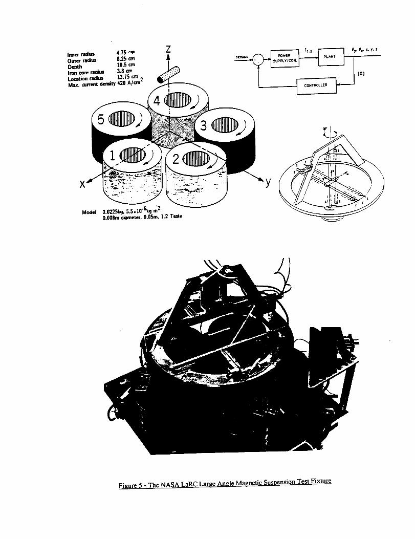
Inner rao"eus 4.75 ,",,Outer radius 8.25 cmDepth 10.5 cmIron core radius 3.8 cmLocation radius 13.75 cmMax. c_,,rremdlmsiiy 420 A/an"
Z
Model
2
3
0.0225k9, 5.5,10"6kg m2o.o08m diameter. 0.0Sin. 1.2 Tesla
Y
Figure 5 - The NASA LaRC Large Angle Magnetic Suspension Test Fixture

Control CoilsZ Levitation Coils
X
Y
Figure 6 - A 6 degree-of-freedom Electromagnet Configuration (from I171)

Application of Magnetic Suspension Technology to Large Scale Facilities
- progress, problems and promises
Colin P. Britcher
Associate Professor
Department of Aerospace Engineering
Old Dominion University
Norfolk, VA 23529-0247
757-683-4916, FAX 757-683-3200, E-mail [email protected]
An extended Abstract submitted for consideration for the NWTC substitute Session,
AIAA 35th Aerospace Sciences Meeting, Reno, NV, January 1997
Introduction
Wind tunnel Magnetic Suspension and Balance Systems (MSBS) have been under
investigation and development since 1957. A significant number of small-scale systems
have been constructed and a variety of aerodynamic testing carried out [ 1]. Current work
in the U.S. is limited, but includes a serious investigation of an application for an ultra-
high Reynolds number wind tunnel, a modest system recommissioning effort, and is
benefiting from a variety of "spin-offs" from generic large-gap magnetic suspension
development work at NASA Langley Research Center. Other work on MSBSs is
currently known to be proceeding in Japan, Taiwan, P.R. China, England and Russia. This
paper will briefly review the previous work in wind tunnel MSBSs and will examine the 8
systems currently in operational condition or undergoing recommissioning. The ultra-high
Reynolds number application will be addressed in some detail. Technical developments
emerging from research programs at NASA and elsewhere will be reviewed briefly, where
there is potential impact on large-scale MSBSs. The potential aerodynamic applications
for large MSBSs will be addressed. Finally, some opinions on the usefulness and
feasibility of a large MSBS will be given.
Current U.S. efforts
Ultra-High Reynolds Number Liquid Helium Tunnel
Research has been underway for several years examining the possibility of constructing an
ultra-high Reynolds number "wind" tunnel with liquid helium as the working fluid [2]. At
one point, the tunnel was referred to by some researchers as the "infinite Reynold's
number" tunnel, since operation with superfluid helium was contemplated and a promise of
effectively zero viscosity of the working fluid was held out. Current work appears to be
focussed on slightly more modest performance (finite Reynold's number!) but could still
result in a facility with a Reynold's number capability one order of magnitude higher than
anything currently existing. The engineering application is clearly to hydrodynamic studies
of submersibles,with the particular item of interest being wake-related signaturereduction. Fundamentalstudiesof high Reynoldsnumberturbulencearealso attractinginterest. It hasbeenassumedthat anMSBS wouldbemandatoryfor this typeof facility,sincea conventionalsupportsystemwould createsevereproblemsby corruption of thevehicle'swake. Researchis proceeding,with recentcompletionof a preliminarydesignandthehostingof a secondworkshop [3,4].
The ODU 6-inch MSBS
If this system were to be described as the ODU/NASA/MIT 6-inch system, then its history
and identity would be clear to all workers in the MSBS field. The electromagnet assembly
and low-speed wind tunnel from the original MIT "6-inch" MSBS [5,6] has found its way
to Old Dominion University, and is currently in process of partial recommissioning. A
unique feature is the use of electromagnetic position and attitude sensing. It is planned to
restore the system to full operation with new power supplies and a digital control system.
International Efforts
The National Aerospace Laboratory in Japan currently operates the largest MSBS ever
constructed, with a test section 60 cm square (roughly 2 feet). Together with a smaller
system (15 cm), current research is focussing on rapid force and moment calibration
procedures [7]. Researchers in Taiwan have recently completed construction of a small
(10 cm) system and are commencing low-speed wind tunnel tests [8]. Russian activity is
at a low level, but includes studies of data telemetry systems from suspended models. One
MSBS remains operational, at TsAGI [9]. Low-density, high Mach number aerodynamic
measurements are continuing at Oxford University in England with their nominally 15 cm
system. A recent development has been the commissioning of a new system at the
National University of Defense Technology in P.R. China, about which information is just
becoming available.
Table 1 -"Operational" MSBSs, 1996
Organization Approx Size Application Status
NASA LaRC 13-inch Low-speed, R&D Inactive
ODU 6-inch System R&D Recommissioning
Oxford Univ. 3-inch Hypersonic aerodynamics Active
MAI/TsAGI, Moscow 18-inch System R&D Inactive
NAL, Japan 4-inch System R&D Active
NAL, Japan 23-inch System R&D Active
NCKU, Taiwan 6-inch System R&D Active
NUDT, P.R. China 6-inch System R&D Active
New Technoio_
A program has been underway for some years at NASA Langley Research Center to
develop technology for large-gap applications of magnetic suspensions. Applications
include,but arenot limited to, wind tunnel MSBSs, space payload pointing and vibration
isolation systems, momentum storage and control devices, maglev trains and
electromagnetic launch systems. Two small laboratory scale levitation systems have been
constructed, with air-gaps between suspended element and electromagnets of 10 cm
[10,11]. A larger system of comparable configuration, the Advanced Controls Test
Facility, is close to completion, with a 1 meter air-gap [12]. This system includes
superconducting coils to provide the background levitation force, with water-cooled
copper control coils. It will represent the largest, large-gap magnetic suspension or
levitation device ever constructed.
An important novel feature is the use of a transversely magnetized permanent magnet core
in the cylindrical suspended element. This provides full six degree-of-freedom control
capability. It has subsequently been realized that this configuration is well suited to the
wind tunnel application, where generation of magnetic roll torque has been a long-
standing problem. Using vertically magnetized permanent magnet cores within the
fuselage provides roughly equal (and large) pitch and roll torque capability. Litt, drag and
sideforce capability will be largely unaffected compared to the conventional axial
magnetization configuration. Only yaw torque is relatively reduced, although it is
observed that aerodynamic yaw torques are seldom dominant.
Aerodynamic Test Requirements and Capabilities
A fresh look at the inherent capabilities of MSBSs and perceived shortcomings in
conventional wind tunnel test capability was recently undertaken [13]. The main points
will be summarized here, with the important rider that they should be taken to represent
only the personal views of this author.
The large system design studies undertaken in the 1980's, under the direction of NASA
Langley Research Center, concentrated on application to an NTF-type wind tunnel. The
main technical justification was the elimination of support interference, which is a major
problem around the transonic regime. Design studies were made for large-scale systems
by General Electric Company [14] and Madison Magnetics Incorporated [ 15,16,17]. The
conclusions were that a very large system was technically feasible, though quite expensive.
A major cost driver was the unsteady (control) force and torque requirement, producing
large cryogen boil-off in conventional superconducting electromagnets.
It seemed (and indeed is) inevitable that the cost of a "large MSBS" would be a significant
fraction of the cost of the wind tunnel in which it would be used. The system under
consideration would have provided static aerodynamic data, free of support interference,
but little else. The technical risk was perceived to be quite high, since the system would
have been around 5 times larger in linear dimension than anything previously attempted
(c.1985, NAL 23-inch system and NASA LaRC ACTF not yet completed). The design
was ultimately seen as constituting an insufficiently attractive program and work gradually
slowed and eventually was stopped, in or around 1990.

Provisionof ansupportinterference-freeaerodynamic test capability is a valuable goal and
should be pursued. However, the precise application needs to be carefully considered.
For instance, while there is no doubt that support interference is major problem in the
accurate evaluation of cruise drag in wind tunnel testing, there exist strategies for its
assessment, such as mounting normally sting-mounted models on blade, wing-tip or fin
supports [18]. This is an expensive process, but it is difficult to construct a persuasive
argument this should be replaced by another apparently expensive process (MSBS).
Valuable generic data could, however, be generated at moderate Reynolds numbers in a
smaller and less expensive facility. Some interesting information was generated using the
13-inch MSBS at LaRC, which included a demonstration of the fact that the drag
correction for sting interference could be as high as 200% (though admittedly not typical,
see [19,20]). It has also been known for some time that support interference can be
particularly significant in cases where the support lies in a separated and/or unsteady wake
or any type of vortex flows [21,22]. The understanding of high angle-of-attack and
unsteady aerodynamics would be greatly improved by the provision of interference-free
test data, especially with the possibility of including fully representative model motions,
such as wing rock. The fundamental research to permit the use of MSBSs at high angles-
of-attack has been done, and suspension at extreme attitudes has been demonstrated, but
the systems have not yet been applied to this type of testing.
An Opinion
It seems that a strong argument can be made that the original program focus was flawed,
insofar as the "cost-benefit ratio" for a system focused largely on support interference
elimination in static testing was never favorable. Instead, it is now argued that the focus
should be on the areas of unsteady aerodynamics and dynamic stability, where
conventional test facilitites are arguably quite deficient. The unique ability of MSBSs to
permit controlled motion through arbitrary trajectories (limited only by force and moment
capability) represents an enormous untapped potential.
Acknowledgements
This work was partially supported by NASA Langley Research Center under Grant NAG-
1-1056, Technical Monitor Nelson J. Groom, Guidance and Control Branch, Flight
Dynamics and Control Division.

References
1. Tuttle, M.H.; Kilgore, R.A.; Boyden, R.P.: Magnetic suspension and balance systems -
a selected annotated bilbiography. NASA TM-84661, July 1983
2. Donnelly, R. (ed.): High Reynolds number flows using liquid and gaseous helium.
Proceedings of the 7th Oregon Conference on Low-Temperatue Physics, published
by Springer-Verlag, 1991.
3. Smith, M.R.; Eyssa, Y.M.; Van Sciver, S.W.: Design of a superconducting magnetic
suspension system for a liquid helium flow experiment. 3rd International
Symposium on Magnetic Suspension Technology, Tallahassee, FL, December
1995. To be published as NASA CR.
4. Donnelly, R. (ed.): Proceedings of the international workshop on ultra-high Reynolds
number flows, Brookhaven National Laboratory, June 1996. To be published.
5. Stephens, T.: Design, construction and evaluation of a magnetic suspension and
balance systems for wind tunnels. NASA CR-66903, November 1969.
6. Covert, E.E.; Finston, M.; Vlajinac, M.; Stephens, T.: Magnetic balance and suspension
systems for use with wind tunnels. Progress in Aerospace Sciences, vol. 14, 1973.
7. Sawada, H.; Suenaga, H.; Kunimasu, T; Kohno, T.: Status of MSBS research at NAL
in 1995. 3rd International Symposium on Magnetic Suspension Technology,
Tallahassee, FL, December 1995. To be published as NASA CR.
8. Lin, C.E; Sheu, Y.R.; Jou, H.L.: Magnetic levitation system design and
implementation for wind tunnel application. 3rd Intemational Symposium on
Magnetic Suspension Technology, Tallahassee, FL, December 1995. To be
published as NASA CR.
9. Kuzin, A.; Shapovalov, G.; Prohorov, N.: Force measurements in magnetic suspension
and balance system. 3rd International Symposium on Magnetic Suspension
Technology, Tallahassee, FL, December 1995. To be published as NASA CR.
10. Britcher, C.P.; Ghofrani, M.: A magnetic suspension system with a large angular
range. Review of Scientific Instruments, July 1983.
11. Cox, D.; Groom, N.J.: Implementation of a decoupled controller for a magnetic
suspension system using electromagnets mounted in a planar array. 2nd
International Symposium on Magnetic Suspension Technology, Seattle, WA,
August 1993, Published as NASA CR-3247, May 1994.
12. Groom, N.J.: Description of the large gap magnetic suspension system ground based
experiment. Technology 2000. NASA Cp-3109, 1991.
13. Britcher, C.P.; Groom, N.J.: Future development of wind tunnel magnetic suspension
and balance systems at NASA Langley Research Center with emphasis on
unsteady aerodynamics and dynamic stability. Presentation at NASA HQ, October
1994, unpublished.
14. Bloom, H.; et al.: Design concepts and cost studies for magnetic suspension and
balance systems. NASA CR-165917, July 1982.
15. Boom, R.W.; Eyssa, Y.M.; Mclntosh, G.E.; Abdelsalam, M.K.: Magnetic suspension
and balance system study. NASA CR-3802, July 1984.
16. Boom, R.W.; Eyssa, Y.M.; Mclntosh, G.E.; Abdelsalam, M.K.: Magnetic suspension
and balance system advanced study. NASA CR-3937, October 1985.

17. Boom,R.W.; Abdelsalam,M.K.; Eyssa,Y.M.; Mclntosh,G.E.: Magneticsuspensionandbalancesystemadvancedstudy- PhaseII. NASA CR-4327,November1990.
18. Carter,E C.: Interferenceeffectsof modelsupportsystems.In AGARD-R-601,April 1973.
19. Britcher, C.P.; Alcorn, C.W.: Subsonic sting interference on the aerodynamic
characteristics of a family of slanted-base ogive-cylinders. NASA CR-4299, June
1990.
20. Britcher, C.P.; Alcorn, C.W.: Interference-free measurements of the subsonic
aerodynamic of slanted-base ogive-cylinders. AIAA Journal, April 1991.
21. Dietz, W.E., Jnr.; Altstatt, M.C.: Experimental investigation of support interference
on an ogive cylinder at high incidence. 16th AIAA Aerospace Sciences meeting,
January 1978.
22. Uselton, B.L.: Sting effects as determined by the measurement of pitch-damping
derivatives and base pressures at Mach 3. 10th AIAA Aerodynamic testing
conference, San Diego, April 1978.