of active magnetic bearings
TRANSCRIPT

AN INTRODUCTION AND CASE HISTORY REVIEW
OF ACTIVE MAGNETIC BEARINGS
by
David A. Weise
Administrative Manager
and
Frank D. Pinckney
Engineering Manager
Magnetic Bearings, Incorporated
Radford, Virginia
David A. Weise is the Administrative Manager of Magnetic Bearings, Incorporated, (MBI), a subsidiary of the Kollmorgen Corporation. He has been with MBI since its formation, in 1984. During this time, Mr. Weise has been involved in multiple activities within the
· company including the technology ac. quisition, design, project, and applica
tions engineering, and marketing. He has authored various papers on magnetic
bearings and has been instrumental in developing the North American applications base. Prior to his employment with M B I, Mr. Weise was employed by the Motion Control Division of Gould, Incorporated.
He received his degree in Electrical Power Engineering Technology from Milwaukee School of Engineering.
Frank D. Pinckney is the Engineering Manager for Magnetic Bearings, Incorporated, (MBI), ofRadford, Virginia. He has been involved with the design and Commissioning of active magnetic bearings in turbomachinery applications since joining MBI, in 1984. Mr. Pinckney was previously employed. by Amoco Chemicals Corporation at the Cooper River Plant in South Carolina.
He holds a bachelor's degree in Mechanical Engineering from Clemson University, and a master's degree in Mechanical Engiiweringfrom Virginia Tech.
ABSTRACT
The concept of magnetic levitation is not a new one and can be easily traced back to the 1800s [1). It is only recently, however, that the congruous technologies of electronic control systems, power electronics, and magnetic materials have begun to merge to make the magnetic suspension device a viable product.
A brief overview is presented of an active magnetic bearing technology [2]. The required systems engineering interface with the machine designer is discussed. Finally, case histories of various turbomachinery in North America presently operating on magnetic bearings are reviewed.
121
BACKGROUND
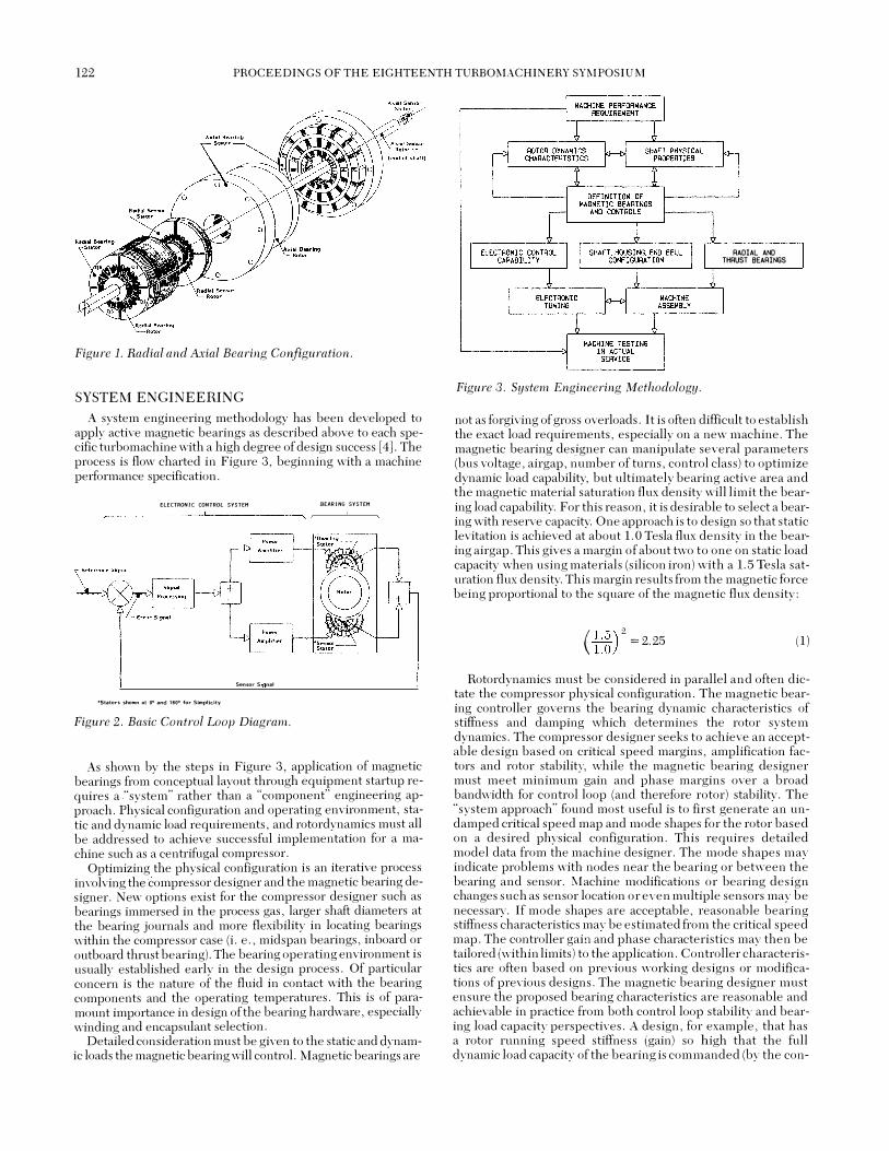
In theory, the principle is quite basic. An electromagnet will attract any piece offerrous material. By using a stationary electromagnet (stator) and a rotating ferrous material (rotor) a shaft can be suspended in a magnetic field while maintaining accurate position under varying loads. This can be accomplished given a small space (air gap) between the stator and rotor and proper electronic control of the electromagnet. In the following case of the active magnetic bearing, this concept is utilized for both radial and axial configurations. It must be noted that the bearing system described here always operates in an attraction mode and never repulsion.
The radial and axial bearing rotors make use of a ferrous laminated sleeve and solid disc, respectively [3]. Applying ferrous rotor elements to the shaft allows the shaft material to be constructed from a nonmagnetic metal or composite material. While the radial bearing requires laminations due to the number of flux reversals during rotation, the axial rotor disc can be solid since the magnetic flux level is changing, but the polarity is not.
As with any type of electromagnet, a wound field stator is required to produce a fo�ce output. Both the radial and axial bearing stators incorporate laminations tqminimize stray losses and improve the bearing response time: The:r�r;l.ial bearing stator is wound to provide four independently controllable quadrants for maximum rotor stability. The axial bearing, ati:racfl��g. the rotor in only one plane, requires the use of two 'stators, onepn either side of the rotor disc, to provide double acting control.
Inductive position sensors are used to 'detect the eli:act radial and axial location of the shaft. Similar to the bearings, these sensors utilize a ferrous rotor and a wound field stator. As the air gap at the sensors· changes with shaft disturbances, the inductance bridge of the sensor also changes. It is this change in inductance with air gap variation, that provides the position feedback signal required for closed loop servo control.
An isometric view of both a radial and double acting axial bearing with their associated position sensors is shown in Figure l.
Control electronics are required to process the position signal and power the appropriatebearing coils. The exact shaft location is detected by the position sensors, and a DC voltage is gener-. ated which is relating to rotor displacement. This DC voltage (where the shaft is) is compared to the position reference signal (where the shaft should be). Any difference between these two signals generates an error signal which is used to maintain control of the rotor. This signal is then amplified, filtered, and conditioned prior to commanding the specified power amplifier(s). Current is increased or decreased in the appropriate bearing coil(s) to maintain the rotor at equilibrium. A basic block diagram is shown in Figure 2 of the closed loop servo control.
122 PROCEEDINGS OF THE EIGHTEENTH TURBO MACHINERY SYMPOSIUM
Figure 1. Radial and Axial Bearing Configuration.
SYSTEM ENGINEERING
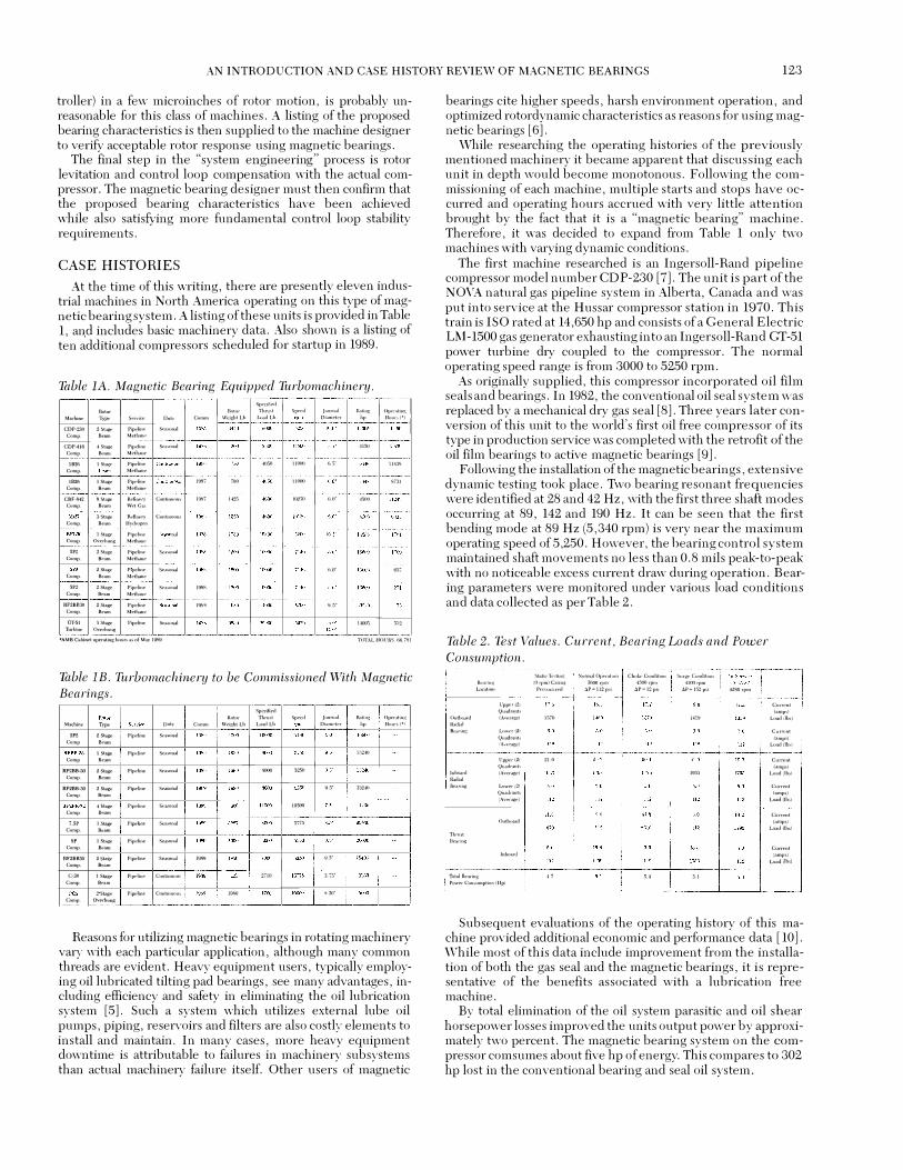
A system engineering methodology has been developed to apply active magnetic bearings as described above to each specific turbomachine with a high degree of design success [4). The process is flow charted in Figure 3, beginning with a machine performance specification.
ELECTRONIC CONTROl SYSTEM BEARING SYSTEM
SensorS n��l
•stators sho•n 111 oa <11nd uoa for Slmplldty
Figure 2. Basic Control Loop Diagram.
As shown by the steps in Figure 3, application of magnetic bearings from conceptual layout through equipment startup requires a "system" rather than a "component" engineering approach. Physical configuration and operating environment, static and dynamic load requirements, and rotordynamics must all be addressed to achieve successful implementation for a machine such as a centrifugal compressor.
Optimizing the physical configuration is an iterative process involving the compressor designer and the magnetic bearing designer. New options exist for the compressor designer such as bearings immersed in the process gas, larger shaft diameters at the bearing journals and more flexibility in locating bearings within the compressor case (i. e., midspan bearings, inboard or outboard thrust bearing). The bearing operating environment is usually established early in the design process. Of particular concern is the nature of the fluid in contact with the bearing components and the operating temperatures. This is of paramount importance in design of the bearing hardware, especially winding and encapsulant selection.
Detailed consideration must be given to the static and dynamic loads the magnetic bearing \\ill control. Magnetic bearings are
Figure 3. System Engineering Methodology.
RADIAL AND THRUST BEARINGS
not as forgiving of gross overloads. It is often difficult to establish the exact load requirements, especially on a new machine. The magnetic bearing desJgner can manipulate several parameters (bus voltage, airgap, number of turns, control class) to optimize dynamic load capability, but ultimately bearing active area and the magnetic material saturation flux density will limit the bearing load capability. For this reason, it is desirable to select a bearing with reserve capacity. One approach is to design so that static levitation is achieved at about 1.0 Tesla flux density in the bearing airgap. This gives a margin of about two to one on static load capacity when using materials (silicon iron) with a 1.5 Tesla saturation flux density. This margin results from the magnetic force being proportional to the square of the magnetic flux density:
( i:�) 2 = 2.25 (1)
Rotordynamics must be considered in parallel and often dictate the compressor physical configuration. The magnetic bearing controller governs the bearing dynamic characteristics of stiffness and damping which determines the rotor system dynamics. The compressor designer seeks to achieve an acceptable design based on critical speed margins, amplification factors and rotor stability, while the magnetic bearing designer must meet minimum gain and phase margins over a broad band\vidth for control loop (and therefore rotor) stability. The "system approach" found most useful is to first generate an undamped critical speed map and mode shapes for the rotor based on a desired physical configuration. This requires detailed model data from the machine designer. The mode shapes may indicate problems with nodes near the bearing or between the bearing and sensor. Machine modifications or bearing design changes such as sensor location or even multiple sensors may be necessary. If mode shapes are acceptable, reasonable bearing stiffness characteristics may be estimated from the critical speed map. The controller gain and phase characteristics may then be tailored (within limits) to the application. Controller characteristics are often based on previous working designs or modifications of previous designs. The magnetic bearing designer must ensure the proposed bearing characteristics are reasonable and achievable in practice from both control loop stability and bearing load capacity perspectives. A design, for example, that has a rotor running speed stiffness (gain) so high that the full dynamic load capacity of the bearing is commanded (by the con-
AN INTRODUCTION AND CASE HISTORY REVIEW OF MAGNETIC BEARINGS 123
troller) in a few microinches of rotor motion, is probably unreasonable for this class of machines. A listing of the proposed bearing characteristics is then supplied to the machine designer to verify acceptable rotor response using magnetic bearings.
The final step in the "system engineering" process is rotor levitation and control loop compensation with the actual compressor. The magnetic bearing designer must then confirm that the proposed bearing characteristics have been achieved while also satisf):ing more fundamental control loop stability requirements.
CASE HISTORIES
At the time of this writing, there are presently eleven industrial machines in North America operating on this type of magnetic bearing system. A listing of these units is provided in Table 1, and includes basic machinery data. Also shown is a listing of ten additional compressors scheduled for startup in 1989.
Table lA. Magnetic Bearing Equipped Turbomachinery. Sp�dfied
... � Rolor Thrw;t Spc!!d Jomnal li.�Un�;t Opcn•tin!:
Marhme T"' Servite """ Comm WeJghtLb t..dLb O!.!metrr bp Hou•1(•)
COP-230 2St;,ge Pipeline St'llsoool Camp. ... m Meth:um
CDP·•II6 """ Plp<!llne s�a.onal ""' Comp. - Mctlwn�
lB .. "'"" PIP<"IIne .. , uaoo 6,5" 114:1!:1 Comp. - M�thane
.... """ Pip<'l!llt' 1007 700 uooo 8731 Comp. Bc�m Melharw
CBF.s42 l!St<�ge Rellnery ConUnUOI" "" "" """ 1023() "' ""' Comp. Be�m WctGa:;
3Sillgl! Rt8uery CD!IIm"""• Comp. ·- H�dn::§t'tl
!Stage Pipeline ..., ... 10� C1;11np. Overhung Methane
'" """' Plfl(!Hn� S1>ownal C01np. B�am Meth�n�
2SUV. Plptohn� SI!<ISom�l O.if 057 Comp. B�m Mt>th.ne
'" """' PipeUn� Se:�M�n�l I"' Comp. - Mo:th�ne
II.F'2BB:l0 ,..,. Plpfflinc s • ..,.onal IB>!l 9.5" C001p. D�Am Meth,me
Cf·5l !Stage Pipeline Se.:ooowl """ '" Thrbin� Overhung
•AMB C..bm!!l oper�tlng: houro"" of M<t� 1� TOTAL HOURS. fl6,'ffll
Table lB. Turbomachinery to be Commissioned With Magnetic Bearings.
Spedllvd Rotor Thru�l Sp�cd Journal Ratio� Operahng
M"'lhine - ""' Comm "'mWltLb LMdLb Diam,•tcr bp Hour:� (•)
"' 2Stag<� Pipeline s�w;omd C.mp ·-
1St� Plpei!oo ''"""" :l..1!:.40 C.mp .. �
..... ., 2Stagc Pipeline Sea:oon.1l """ '"" Comp. ·�·
RF"'B-30 J!SI:ilj;e Plpcllnc S...u;arn�l '� ""'' Comp. B�m
4Stage Plpei!IIC St3Min�l 10500 Comp. ·�·
7.SP l5"V Pipeline Seasonal 5775
Comp. ··-
" """ Pipdine Scalr(lnol Comp. ....
RF�BB30 J!Stage P\pel!ne '�""" "'' 9.5" Comp ....
C-30 """' Pipdin,. ConiLnuou� :mo J:.>,S ."),;::;• Comp. B�m
!Sbge Pipt>hn<' Cont!nuou� I"" '"' Comp. O..on-buns
Reasons for utilizing magnetic bearings in rotating machinery vary with each particular application, although many common threads are evident. Heavy equipment users, typically employing oil lubricated tilting pad bearings, see many advantages, including efficiency and safety in eliminating the oil lubrication system [5]. Such a system which utilizes external lube oil pumps, piping, reservoirs and filters are also costly elements to install and maintain. In many cases, more heavy equipment downtime is attributable to failures in machinery subsystems than actual machinery failure itself. Other users of magnetic
bearings cite higher speeds, harsh environment operation, and optimized rotordynamic characteristics as reasons for using mag-netic bearings [6].
·
While researching the operating histories of the previously mentioned machinery it became apparent that discussing each unit in depth would become monotonous. Following the commissioning of each machine, multiple starts and stops have occurred and operating hours accrued with very little attention brought by the fact that it is a "magnetic bearing" machine. Therefore, it was decided to expand from Table 1 only two machines with varying dynamic conditions.
The first machine researched is an Ingersoll-Rand pipeline compressor model number CDP-230 [7]. The unit is part of the NO\'A natural gas pipeline system in Alberta, Canada and was put into service at the Hussar compressor station in 1970. This train is ISO rated at 14,650 hp and consists of a General Electric LM -1500 gas generator exhausting into an Ingersoll-Rand GT-51 power turbine dry coupled to the compressor. The normal operating speed range is from 3000 to 5250 rpm.
As originally supplied, this compressor incorporated oil film seals and bearings. In 1982, the conventional oil seal system \Vas replaced by a mechanical dry gas seal [8]. Three years later conversion of this unit to the world's first oil free compressor of its type in production service was completed with the retrofit of the oil film bearings to active magnetic bearings [9].
Following the installation of the magnetic bearings, extensive dynamic testing took place. Two bearing resonant frequencies were identified at 28 and 42 Hz, with the first three shaft modes occurring at 89, 142 and 190 Hz. It can be seen that the first bending mode at 89 Hz (5,340 rpm) is very near the maximum operating speed of 5,250. However, the bearing control system maintained shaft movements no less than 0.8 mils peak-to-peak with no noticeable excess current draw during operation. Bearing parameters were monitored under various load conditions and data collected as per Table 2.
Table 2. Test Values. Current, Bearing Loads and Power Consumption.
SIAticT<",Ung Normal Operation Ch<lkeCondition S<irg.,Condlhuo B<-ll•1nJ! (llrpm)C�!!>g 3000rpm 4000rpl<! 4100rpm
l..oc<Ltion Pre<>im:wd J.P., Ill! poi ;1P=l2psl .. 1P .. l52p$i 421:!0rpm
Upptor(2) Qu<Kir�nts
Outbo.Jrd (:\ver�J 1370 loK\9 R:.di�l BM:ill.!> Lowcr(2)
QuWr�nt< IAv<-ntge)
Upp�r (2) 21.0 Quadf:mh
lnbOOLrd (Awragv) ""' .... 1 Be�ri11g Llwer(2)
QufLdr!lniJ (Ave("'i<')
Outbo,ud
Thru�t D��ring
lnbuard
TotAl 'Waring 47 •.. 5.1 POW\!rCon•umpll<m(Hp)
Corron! {<tmpo)
L<mdilmJ
Cuf'fflnl (�mps)
!Aad(!lr.J
Current (�mp!)
Lo:«l (lbs)
Current (amp'<)
Load (lb�)
Current (amps)
Lo�d (!b�l
Current (amp>;)
Lo.ul\lb!)
Subsequent evaluations of the operating history of this machine provided additional economic and performance data [10]. While most of this data include improvement from the installation of both the gas seal and the magnetic bearings, it is representative of the benefits associated with a lubrication free machine.
By total elimination of the oil system parasitic and oil shear horsepower losses improved the units output power by approximately two percent. The magnetic bearing system on the compressor comsumes about five hp of energy. This compares to 302 hp lost in the conventional bearing and seal oil system.

124 PROCEEDINGS OF THE EIGHTEENTH TURBO MACHINERY SYMPOSIUM
Maintenance savings were also calculated and determined to be a rather substantial figure. With the total absence of contacting stationary and rotating components, no wear related maintenance was seen. Also maintenance to the lubrication and seal oil subsystems was eliminated. Overall machinery maintenance, call outs, and downtime have been reduced by 85 percent. With the total average scheduled maintenance cost for the compressor and associated equipment of $41,250 and $22,500 typically related to call outs and unscheduled maintenance, an annual maintenance savings of $54,187 was calculated.
Based on these maintenance savings and the additional savings associated with oil consumption and oil and pipeline contamination a payback period of 4.4 years is anticipated for this retrofit. Installation of magnetic bearings and dry gas seals in a new compressor, where the initial bearing and seal costs are offset by not purchasing a bearing and seal oil system can improve the payback period to less than one year.
A SPECIFIC APPLICATION
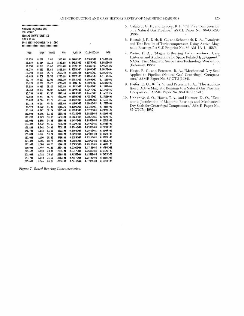
Another specific application is reviewed to highlight some details of the system engineering involved in an actual machine. The application was a magnetic bearing retrofit of a single stage natural gas pipeline compressor (4]. The machine had a 700 lb rotor operating at a maximum speed of 11,700 rpm. The radial bearings had a maximum load capacity of 890 lb per bearing quadrant. Static levitation was achieved at 0.8 Tesla flux density in a 0.020 iri airgap. The compressor had a conventional physical configuration with all bearings outside of the process gas and the thrust bearing inboard of the radial bearings. Operating speed was under the first shaft bending mode (3rd critical) as shown in Figure 4. The first and third free-free (low bearing stiffnes!>) mode shapes are shown in Figure 5 and Figure 6, respectively. The final controller gain and phase and resulting bearing stiffness and damping characteristics are shown in Figure 7. The bearing stiffness (k) and dynamic stiffness (K) are also plotted on the critical speed map (Figure 4). The dynamic stiffness K is the vector sum of the (real) stiffness and the (imaginary) damping stiffness and is noted as "KMAG" in Figure 7. Although a high gain control loop (i. e., stiffer bearings) were initially proposed, it was found during site tuning to cause the shaft second mode to encroach on the operating speed range. The data shown reflect the actual bearing characteristics as measured during startup at the site. A second machine, identical to the first unit, has since been commissioned. Controller and bearing characteristics of the two units are identical. At the time of this writing, two units have more than 20,000 hrs of operation.
M00.6 4
to'
to'I,�O'r--+--+--+-+--+-H-I;t*-0 ,.----+---+--+---<e+-+-H;IIO;r--+-----1-+-1-4-f-t-i;IIO' !II.FPGI1' mmes �lb/tn)
JIJI .1lllt MIXI7 llH!D u .... FliP 2-U-fJ7
Figure 4. Critical Speed Map.
M A G N E T I c 8 E A R I N G s
SHAFT AXIAL POStnQtr4, INCl£5
,..,., ftl>t0-1-88
l.t«Wf'EDN-.ruw...FF!Etl�Eta ICPMI: 1008
8EARIN&STIFFI£SSIL.8/INI: t.OE4
Figure 5. Mode Shape.
� o.
i T I
I
-o.
......
... ,.
stW'T AXIAL POSITION. INCt£9
""'' FOP to-t__,
l.fiJNftD NAlUIM. FFIEIUNCY ICPMl: 1l!•t'7!S
BEUIINI!JTIFFNESSWINI:t.OE-4
Figure 6. Mode Shape.
CONCLUSION
Magnetic bearings have proven to be a viable and attractive alternative to conventional bearings. Lubrication free equipment capable of harsh environment operation is definitely seen as the future of many types of rotating machinery. \Vhile turbomachinery users have benefitted greatly from applying magnetic bearings to existing designs, substantial advances can be made in rotating equipment by fully exploiting all of the operational advantages of magnetic bearings in future generation machinery.
REFERENCES
1. Earnshaw, S., "On the Nature of the Molecular Forces " Trans. Cambridge Phil. Soc. 7, pp. 97-112, (1842).
'
2. \Veise, D. A., "Active Magnetic Bearings Provide Closed Loop Servo Control for Enhanced Dynamic Response," 27th IEEE Machine Tool Conference (October 1985).
3. Weise, D. A., "Present Industrial Applications of Active Magnetic Bearings," 22nd IECEC'87 Philadelphia, Pennsylvania (August 10-14, 1987).
4. Moses, H. J., Pinckney, F. D:, and Weise, D. A., "!\lagnetic Bearing Turbomachinery Operating Experience," First International Symposium on Magnetic Bearings, Zurich, (1988).
AN INTRODUCTION AND CASE HISTORY REVIEW OF MAGNETIC BEARINGS 125
fflflfffHffltfffftfflfffiUffi 5. Cataford, G. F., and Lancee, R. P. "Oil Free Compression MAGN6TIC BEARIIfiS INC JOB 159007
on a Natural Gas Pipeline," ASME Paper No. 86-GT-293
BEARING CHARACTERISTICS (1986).
TUNED ll-86 6. Hustak, J. F., Kirk, R. G., and Schoeneck, K. A., "Analysis SF=318265 K=34500etai!N @ 158HZ ffflfffHtfffttfiHt-fffHfffflf
and Test Results of Turbocompressors Using Active Mag-netic Bearings," A.SLE Preprint No. 86-A�l-1A-1, (1986).
FREQ SA IN PHASE RP� �.I.B/IN C,LB•SEC!IN KMAG 7. \Veise, D. A., "Magnetic Bearing Turbomachinerv Case
32. 75� 0.298 7. 85 1965.00 0. 9408E+05 e. 6300E+I!2 e. 9497E+05 Histories and Applications for Space Related Equipment,"
35.110 0.304 :2.33 2105.68 0. 94&1E+05 �. 9375E+IIC: 0. %85E+05 NASA, First Magnetic Suspension Technology \Vorkshop,
17.650 0.312 16.67 225;.1!9 0. 95�5E+05 0.1206E+03 0. 9943E+05 (February, 1988). 40.370 0. 323 20.83 2422.29 0. 959YE+I� e.t440E+03 0.1027E+96 8. Hesje, R. C. and Peterson, R. A., "Mechanical Drv Seal •3. 291! 0. 335 24.79 2597.40 0. 9685E+05 0.1645E+03 0.1067E+06
4Q'.420 0. 350 28.53 2185.29 0. <J787E+05 I. 1824£+03 0.1 114E+06 Applied to Pipeline (Natural Gas) Centrifugal Co�pres-
49. 771! 0.367 32.02 2986.20 0. 990JE+05 0. i980E+03 0.ll68E+06 sors," A.SME Paper No. 84-GT-3 (1984). 53, 37a 0. 38i 35.27 3202.211 0.1105E+86 0. 2119E+03 0.1230E+% 9. Foster, E. G., Kulle, V., and Peterson H. A., "The Applica-57. 22� 1!.409 38.28 3433.211 0.1021E+06 0.2240E+03 0.1300E+06
61.36� 0.433 41.02 3681.68 0. 1840E+i6 0. 2347£+03 0. 1378E+\l£ tion of Active Magnetic Bearings to a Natural Gas Pipeline
65.790 �. 4&1 �3. 52 39\l.�i i. 1063£+06 e.2441E+� e.t466E+06 Compressor," AS:tviE Paper No. 86-GT-61 (1986). 70.550 0.491 45.77 4233.01 0.1099E+86 �. �526E+IJ 0.15&2i+e& 10. Uptigrove, S. 0., Harris, T. A., and Holzner, D. 0., "Eco-75.650 e. sz� 47. i6 45JS.ili 0. 1122E+06 e.2600E+�3 0. lb69E+06
81.110 0.561 49.51 4866.68 e. 1161!€+86 0.2666E+t3 0.1786E+86 nomic Justification of Magnetic Bearings and Mechanical
86.971 e.�2 51.01 5216. 2i e.t28SE+06 9.2/25E+I3 0.1916£+06 Dry Seals hJJ· Centrifugal Compressors," ,\SME Paper No. 93.260 U47 52.24 5595.60 e. J260E+eG 9. 2777E+I3 9. 2058E+e!i 87-GT-174 (1987).
100.000 0.696 53.23 600Ui 0. 1325E+e& 0. 2822E+03 0. 2214£+�6
107.200 �. 749 53.95 6432. 0t 0.1403£+06 0. 2862E+I3 0. 2384£+1!6
115.00\l 9.888 54.11 &900.� �. 1497£+06 0.2893£+03 0.2571£+0&
123.300 �.872 54.56 7398.08 0.1609E+e!i e. 29t9E+eJ e. 2775£+eG
!32.208 e. 942 54.42 7932.18 0. 1744£+06 e. 2935E+0J 0.2998E+06
141.718 1.818 53.96 8502.ell 0.1905E+86 e. 29431:+03 0. 3241!E+e!i
152.el!e 1.181 53.2i 9121.0e e. 2099£+06 e. 2938E+03 e. 3504E+0&
163.000 1.198 52.115 9788.00 e. 2J<:'lE+86 0. 2916E+I3 0. 3787E+06
174.808 1.286 58.51 10488.08 0.2603£+86 0. 2876£+03 0. 4093E+06
187.400 1;388 48.53 11244.00 0.2925E+06 e. zsuE+03 0. 4418E+96
200. 90e 1.497 46.06 12854.00 e. 3306E+06 e. Z71BE+0J 0. 47&4£+0&
215.400 1.618 U01 12924.01 0. 3747£+86 0. 2583£+03 0.5124£+06
231.008 1. 72& 39.27 138i>Ui e. 4253E+06 0. 2396E+03 0. 5493E+06
247. 700 I. &49 3�.66 14862.01 0.4817E+96 0. 2140E+t3 0. 5856£+06
265. 610 1.944 28.91 15936.08 0. 54 16£+06 0. 1792E+03 0.6187E+06
Figure 7. Tuned Bearing Characteristics.

126 PROCEEDINGS OF THE EIGHTEENTH TURBO MACHINERY SYMPOSIUM