guatemala solar food dehydrator: final design implementation
TRANSCRIPT
Guatemala Solar Food Dehydrator: Final
design Implementation
By: Bingchen Chi, Joshua Cresswell, Dylan
Etheridge & Reace Head
To: The people that will boldly face new
challenges and adapt to an ever Changing
world
Table of Contents Executive Summary .................................................................................................................................... i-ii
Introduction .................................................................................................................................................. 1
Design Parameters .................................................................................................................................... 2-4
Updraft Solar Dehydrator ....................................................................................................................... 5-10
Downdraft Solar Dehydrator ................................................................................................................ 11-15
“S” Air Flow Pattern Dehydrator .......................................................................................................... 16-17
Solar Cabinet Dryer .................................................................................................................................... 18
Mixed Mode Solar Energy Dryer ................................................................................................................ 19
Heat Transfer Calculations .................................................................................................................... 20-22
Equations ............................................................................................................................................... 23-26
Best Design ............................................................................................................................................ 27-30
Final Design............................................................................................................................................ 31-36
Experimental Setup ............................................................................................................................... 37-40
Updraft Data and Results ...................................................................................................................... 41-50
Discussion of Results ............................................................................................................................. 51-53
Future Improvements ................................................................................................................................ 54
Conclusion .................................................................................................................................................. 55

1
Introduction
Food dehydrators are used to preserve fruit, vegetables, and animal proteins
after harvest. The citizens of Panyebar, Guatemala need a food dehydrator to preserve
the micronutrients needed to feed themselves and their children. If the children do not
get the proper amount of micronutrients, their growth can be stunted, education
stalled, and their development hindered. The goal of this project is to make sure the
children receive the proper amount of micronutrients each day so that they can grow
and develop normally.
A decision matrix was made to analyze the important parameters that govern the
quality of a solar food dehydrator. Many of these parameters were determined to be
important based on information given by the contact in Panyebar and through the
knowledge of the engineering topics that are relevant to solar dehydrators such as heat
transfer and fluid mechanics. After the completion of the decision matrix, multiple types
of solar dehydrators were benchmarked in relation to the decision matrix. In the end,
the updraft solar dehydrator was determined to be the best dehydrator for Panyebar’s
needs. This will be shown through theoretical and experimental testing.

2
Design Parameters
A Quality function deployment matrix was initiated to determine the Design
Parameters that were considered to be of highest priority to effectively satisfy the
needs in Guatemala.
Figure 1. Design Parameters Chart
The Quality function deployment matrix was analyzed providing six key design
parameters of focus. It was believed that by satisfying the six parameters, the quality
function would encompass the needs of the Guatemalan customers and be cross
functional in satisfying the remaining design parameters qualifying attributes. The six
design parameters are listed below:
Color Correlation
Strong
Average
Weak
Customer
Importance
Wieghting
Product
CostFunction Quantity Quality Safety
Environmental
Issues
Energy
ConsumptionReliability
Service
Life
Mechanical
Loading
Maintenance
ProceduresWeight
Ambient
Evironmental
Conditions
AestheticsNoise
RadiationPersonnel
Transportation
& Packaging
Spatial
Constraints
Operating
Instructions
Government
Regulations
Human
Factors
Operating
Costs
Shelf-life
Storage
$500 Limit But
as low cost as
possible
10
Avoid Toxic
materials10
Use of thermal
mass5
Portability a
bonus2
Half the size of
Panyabars
schools
Dehydrator
6
Capable of
drying 2 lbs. of
sliced product
at a time
10
1 to 2 day
loads10
Well ventilate 8
No mold from
drying
overnight
10
Able to
dehydrate
bananas,
apples,
oranges,
mango, papaya
and pinapple
10
able to dry 80
bananas at a
time
10
Operational by
Teachers and
Mothers
10
Check on fruit
intermitantly
through the
day
5
Protected
from ants8
protected
from fruit flies8
Dust protected 8
Wheels for
moving into
direct sun
5
3
Product Cost: Cost will be below $500 by using cost effective materials that have
widespread use in the Panyebar region. Design will have dimensional awareness being
frugal on material use. Simple design concepts like using water for thermal capacities
and insect protection will help drive cost down. Majority of customer specifications
require extra cost but through simple design concepts these specifications will be met
while keeping below budget of $500 and will strive for cheaper design strategies to
minimize cost on all levels.
Function: Product should be functional on all levels required by the citizens of
Panyebar. Eighty banana capacity with zero waste of food product due to mold growth.
The dehydrator will have capabilities of drying bananas, tomatoes, apples, oranges,
mangos, papaya and pineapple. It will make use of a thermal capacity to help deter
mold growth overnight and be capable of dehydrating loads in less than 2 days. There
will be zero contamination of the food product within the unit from bugs and outside
debris with capabilities of moving the dehydrator to sunnier areas by two mothers or
teachers.
Safety: Made for a school playground operated by mothers and teachers, safety is of
the utmost importance. The dehydrator will have to be sturdy when operated under
ordinary moving procedures to prevent injury from tipping. There will be zero mold
growth on food product to prevent cases of toxic molds. Protection from bugs must also
be maintained. There will be no sharp or pointy edges to prevent injures due to any run
in encounters from children on the playground. Toxic materials will be excluded from
the entirety of the building to keep micronutrients edible.
4
Reliability: A dehydrator is a large investment for a village with little income; when
the dehydrator does its function it will perform to success every time. Success is
determined by zero visible mold growth in a dehydration period of two days or less
through easy routine procedures that a mother or teacher can accomplish daily.
Quality: Having a low budget solar dehydrator does not mean you spare on the
quality of the design, it means you work harder to find unique solutions that still
maintain the standards set by customers and design team. Nontoxic materials,
aesthetically pleasing, longevity without decay all while meeting function goals and
staying in under the $500 budget.
Operating Instructions: Solar dehydrator manufacturing and operating instructions
are key drivers to a successful delivery. The device will be made on site in Panyebar by
rural handymen or women, this means instructions have to be clear and concise for
them to follow. During operations teachers and mothers will be handling the day to day
activities, and the providing instructions from one language to another has its hurdles.
These issues will be curtailed by providing clear step by step instructions that are
pictured orientated with a professional translation from English to Spanish.
Of course all design parameters will be kept in the decision making process, but
it has been found evident that these six are the heavy hitters that seem to touch every
specification and are connected to all other parameters.
5
Updraft Solar Dehydrator
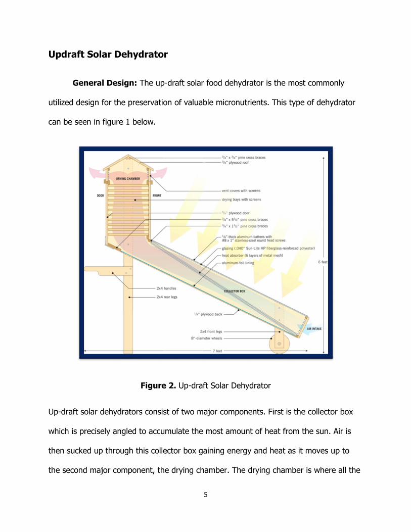
General Design: The up-draft solar food dehydrator is the most commonly
utilized design for the preservation of valuable micronutrients. This type of dehydrator
can be seen in figure 1 below.
Figure 2. Up-draft Solar Dehydrator
Up-draft solar dehydrators consist of two major components. First is the collector box
which is precisely angled to accumulate the most amount of heat from the sun. Air is
then sucked up through this collector box gaining energy and heat as it moves up to
the second major component, the drying chamber. The drying chamber is where all the
6
food that needs to be dehydrated is kept. Hot air rises through polypropylene drying
racks full of food and exits through two vents at the very top of the dehydrator.
A main advantage of this design is that many similar dehydrators have been built
in the past, giving it a strong proof of concept. This dehydrator being the most widely
used device means that there is an ample amount of data on it. Meaning that the work
for determining the heat transfer calculations, fluid flow calculations, the optimum angle
for the collecting box, the best materials to use, the best size for specific design
specifications, and the instructions on how to manufacture it are all easily accessible
and quickly found online or in books. All of this also offers the advantage of speed in
designing and building time as compared to the other dehydrators. This design is not
without its disadvantages however. The first and main disadvantage is that this design
can have poor ventilation, which is necessary to keep mold from growing on and
around the fruits and vegetables. This poor ventilation is caused by the hot air that is
rising through the drying chamber. It gains moister and drops in temperature as it
heats the food. This can cause the air to gain enough moister and cool off enough so
that it does not completely exit through the top of the dehydrator. Another
disadvantage is that for the design parameters needed, this type of solar food
dehydrator will be quite tall. This will require the operator to use a ladder to load and
unload the food which can be very cumbersome and time consuming. Other
disadvantages include the bulkiness of the design may make it too large and heavy to
be transportable by malnourished women. In addition, this design would provide less
contribution to the study of the most effective solar dehydrator, due to a less amount of

7
unique innovation. A quick overview of the advantages and disadvantages of the
dehydrator can be seen in table 1 below.
Table 1. Up-Draft Dehydrator Advantages/Disadvantages
Up-Draft Solar Food Dehydrator Advantages Disadvantages
Lots of Data Poor Ventilation
Quickly Manufactured
Requires Ladder to Load Food
Collector Box (Component 1): The goal of the collector box, seen in figure 3
below, is to increase both the temperature and the velocity of the air flow.
Figure 3. Collector Box Simplified Conceptual Image
A great advantage of the updraft design is that each of these two parameters work
together to increase the other. As air enters the bottom of the collector box, it is
subject to heat through radiation. As the air gets warmer, it wants to rise up through
8
the dehydrator, which increases the velocity of air flow. Thus, as much heat as possible
must be maintained in the collector box. The box is covered with a polycarbonate
plastic top. This clear plastic has a very large transparency, allowing the over ninety
percent of solar radiation to enter the system. At the same time, this material exhibits
low conductivity making it a good insulator to keep temperatures high by trapping the
heat once it has entered the system. While a transparent material is wanted at the top
of the collector box, the opposite is wanted on the bottom and sides of the material. A
high heat black sating spray paint will be used on the wood that makes up the bottom
and sides of the collector box. This paint will increase the absorptivity of the wood,
allowing it to absorb maximum solar radiation. At the same time, the paint also
increases the emissivity, causing the wood to act close to an ideal blackbody, itself
radiating a large amount of heat gained to the air flow inside the box. Finally,
reflectivity will be tested by adding reflective materials around the outside of the
collector box. These reflective surfaces will be aligned to increase the amount of solar
radiation hitting the polycarbonate top and in turn, entering the collection chamber.
The alignment of the collector box will be positioned at a 27.5 degree angle to
the ground. This calculation was determined based upon the latitude of Panyebar,
Guatemala being 27.5 degrees as well. The heat gained through convection will want to
be optimized as well. In order to do this, multiple mechanisms will be tested and added
inside the collector box. One option is to add conductive mesh wire that rises diagonally
with the collector box. A second option is to create an array of fins that extrude from
the bottom of the collector box. By adding fins, the surface area perpendicular to the

9
flow is greatly increased. This can be an easy and cost effective way to gain heat
through convection, as shown by the relationship in equation 1.
The effects of adding fins and conductive mesh wire will be tested in a lab by adding
heat lamps above the collector box. A cause of concern with these additions is that they
will decrease the velocity of the airflow. To measure this possible disadvantage,
anemometers will be used to measure the velocity differential between the intake and
the top of the collector box for this experiment.
Drying Chamber (Component 2): Once the hot airflow reaches the top of the
collector box, it moves into the drying chamber and continues to rise up the drying
chamber toward the chimney. Mat Black paint will be used on the outside walls of the
drying chamber, to increase the temperature within. In the drying chamber five
polypropylene drying racks will be placed on shelves. An advantage of this drying
chamber design is that because it is located above the collector box, the warm airflow
will continue to rise across the trays, to dry the fruit. This allows the temperature of the
airflow to remain close to the maximum temperature, achieved through the collector
box, for the entirety of the drying process. Also, as the fruit drys the water vapor will
want to rise due to its molecular mass (18 grams per mole) being small in comparison
to that of air (28 grams per mole.) The buoyancy created will work with the design of
the drying chamber to pull the water vapor up the chamber and out of the dehydrator
though the chimney at the top.

10
Mobility: In order to fit the design parameter of mobility, wheels will be placed
on the front and possibly the back legs of the dehydrator. One concern with this model
is that the bulk of the design will make it too heavy to be transported by malnourished
women. For this reason, the design scaling may be reduced and multiple dehydrators
will be used if need be.
11
Downdraft Solar Dehydrator
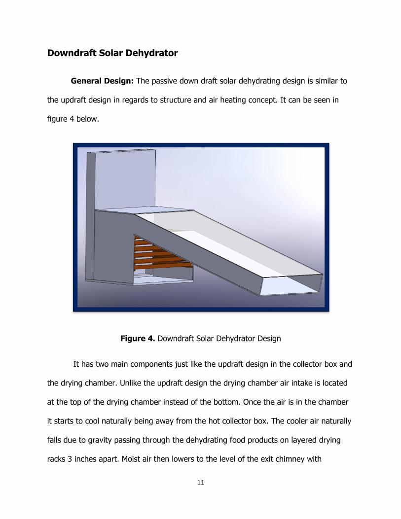
General Design: The passive down draft solar dehydrating design is similar to
the updraft design in regards to structure and air heating concept. It can be seen in
figure 4 below.
Figure 4. Downdraft Solar Dehydrator Design
It has two main components just like the updraft design in the collector box and
the drying chamber. Unlike the updraft design the drying chamber air intake is located
at the top of the drying chamber instead of the bottom. Once the air is in the chamber
it starts to cool naturally being away from the hot collector box. The cooler air naturally
falls due to gravity passing through the dehydrating food products on layered drying
racks 3 inches apart. Moist air then lowers to the level of the exit chimney with

12
adjustable ventilation. Taking advantage of the pressure differential between the hot
humid air on the bottom of the drying chamber and the cooler ambient air outside, a
suction is created nurturing ventilating flow throughout the drying chamber.
Collector Box: The collector box is positioned 27.5 degrees from the ground to
match the average angle of the sun’s approach year around in Panyebar. Inside the
collector box a trough of mat black steel lath will be laid at an angle of 45 degrees
spanning from the top of the collector box to the bottom of the collector box and
layered to capture heat from the sun and actively conducting heat to the cooler air that
is passing through the collector box. The top of the collector box is covered with a
polycarbonate plastic top that will allow the solar radiation energy to pass through but
prohibit the long wave thermal energy from escaping, essentially creating a greenhouse
effect inside the collector box.
Drying Chamber: Five wood framed with molded polypropylene mesh drying
racks placed inside the drying chamber with the dimensions of 39’’ by 27’’ will provide
food drying space of up to 80 bananas. Figure 5 below shows a schematic of the drying
chamber and drying racks.

13
Figure 5. Downdraft Solar Dehydrator Drying Chamber (left) and Drying Rack (Right)
The inside dimensions of the drying chamber provide enough spacing on each side of
the drying racks to avoid lack of flow over the food product due to viscous boundary
layers. The seams caused by the wood not being fastened together perfectly will be
caulked to ensure minimal air leakage from systems chamber. This along with insulation
will increase the air flow of the system and prevent heat loss. Inside walls of the drying
chamber will be fortified with an aluminum foil coating to prevent radiant heat loss.
Four ventilation holes with a 5” diameter will be placed at the bottom of the drying
chamber. A wood plank with a handle will have corresponding wood circles of 5”
diameters to provide for adjustable flows through the chamber with clear indicating
markers for fully closed and fully open. The back walled chimney will be made from
sheet metal that has been painted black; using a black body to help absorb heat into
the conductive sheet metal that will help heat the air that is leaving the chimney

14
nurturing more suction and air flow through entire system. Above the chimney will be a
simple roof design with slanted tops that will traverse any rainfall away from chimney
chute.
Figure 6. Dimensioned Downdraft Design
The air inflow and exits will be guarded with mosquito netting to protect from bugs and
debris invading the system.
Mobility: The drying chamber and collector box will be based on supports made
by 2” by 4” boards, attached to this base will be 4 wheels where the 2 front wheels will
have rotating caster capabilities much like the front of a shopping cart. The wheels
when stationary will be placed in pans of water, these pans will be moats of water to
protect the 4 lands entrances from land crawling bugs such as ants.
15
The benefits of the down draft model is that it will not require any assistance to
elevate oneself to reach the drying racks in the drying chamber; no ladders equals safer
operation. Having the bulk of the dehydrator lower to the ground provides a lower
center of gravity, this will help prevent tipping in a playground environment. All
materials needed for downdraft design can be easily allocated in Guatemala. Through
research it has been claimed that the down draft design provides better results on
cloudy days, it is suspected if this is found to be true that it might be beneficial in
preventing mold growth due to lack of sun overnight. Tests will be done to investigate
these claims.

16
"S" Air Flow Pattern Dehydrator
Figure 7. “S” Air Flow Pattern Dehydrator
The “S” air flow pattern dehydrator shown in figure 7 above has a collector box
similar to that of the updraft and downdraft solar dehydrators. This collecting chamber
will be positioned 27.5 degrees above the horizontal, which is the ground. The collector
has an air intake at the bottom and will be the part of the dehydrator that heats the air.
It will have a transparent polycarbonate plastic cover on the top, a steel lath absorber
inside, and thermal insulation on the sides of the collector box. The air path in the inner
part of the dehydrator looks like an “S.” This design maximizes the heated air utilizable
ratio in the dryer. When the dryer is working, heated air will go through each part of
the trays and have relatively similar thermal mass. A PV panel is installed in the front
side of the dryer with changeable declination angle. On the top of dryer, there is a
chimney with a PV operating fan. It is planned to strengthen the air flow. The dryer is
17
useful in a low temperature and friendly environment situation. Drying fruits and
vegetables in Guatemala where thunderstorms and rain are high make this dehydrator
questionable.
18
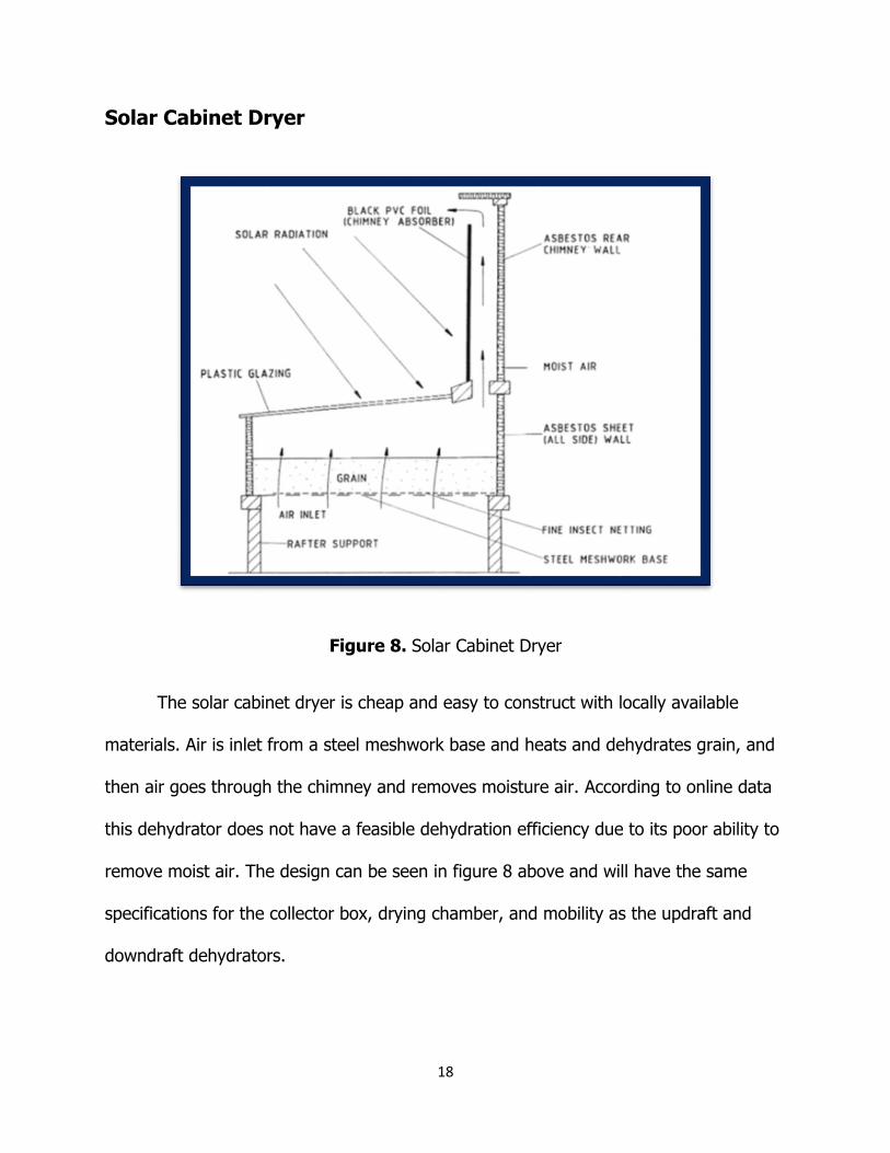
Solar Cabinet Dryer
Figure 8. Solar Cabinet Dryer
The solar cabinet dryer is cheap and easy to construct with locally available
materials. Air is inlet from a steel meshwork base and heats and dehydrates grain, and
then air goes through the chimney and removes moisture air. According to online data
this dehydrator does not have a feasible dehydration efficiency due to its poor ability to
remove moist air. The design can be seen in figure 8 above and will have the same
specifications for the collector box, drying chamber, and mobility as the updraft and
downdraft dehydrators.
19
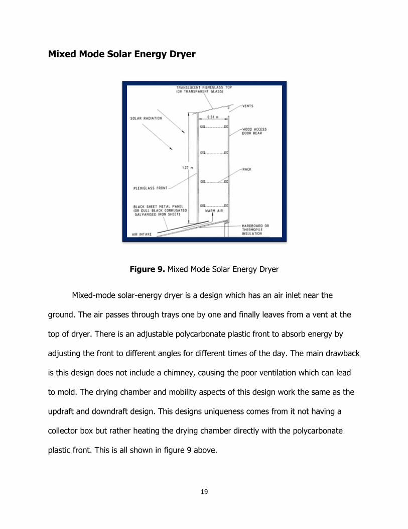
Mixed Mode Solar Energy Dryer
Figure 9. Mixed Mode Solar Energy Dryer
Mixed-mode solar-energy dryer is a design which has an air inlet near the
ground. The air passes through trays one by one and finally leaves from a vent at the
top of dryer. There is an adjustable polycarbonate plastic front to absorb energy by
adjusting the front to different angles for different times of the day. The main drawback
is this design does not include a chimney, causing the poor ventilation which can lead
to mold. The drying chamber and mobility aspects of this design work the same as the
updraft and downdraft design. This designs uniqueness comes from it not having a
collector box but rather heating the drying chamber directly with the polycarbonate
plastic front. This is all shown in figure 9 above.
20
Heat Transfer Calculations
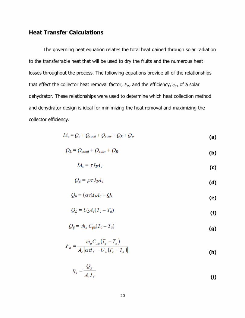
The governing heat equation relates the total heat gained through solar radiation
to the transferrable heat that will be used to dry the fruits and the numerous heat
losses throughout the process. The following equations provide all of the relationships
that effect the collector heat removal factor, 𝐹𝑅, and the efficiency, 𝜂𝑐, of a solar
dehydrator. These relationships were used to determine which heat collection method
and dehydrator design is ideal for minimizing the heat removal and maximizing the
collector efficiency.
(a)
(b)
(c)
(d)
(e)
(f)
(g)
(h)
(i)
21
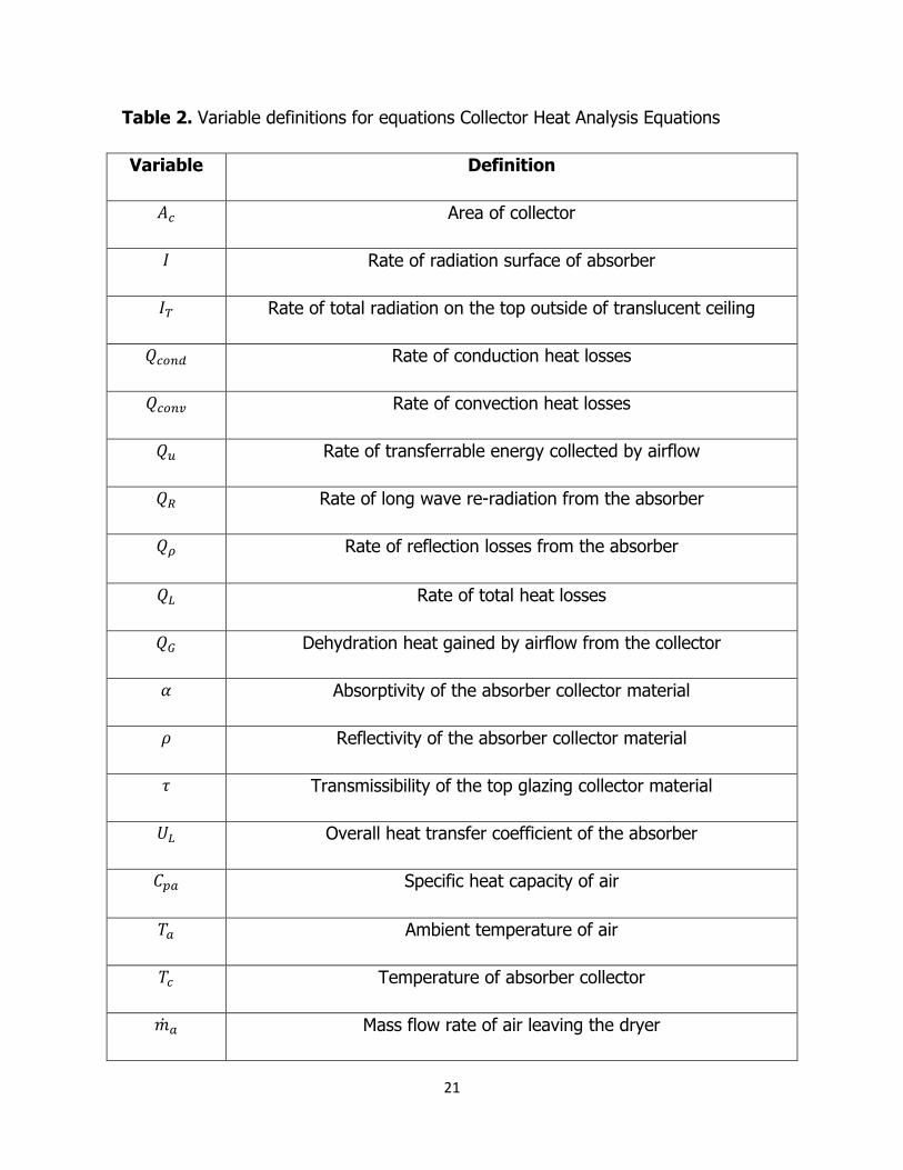
Table 2. Variable definitions for equations Collector Heat Analysis Equations
Variable Definition
𝐴𝑐 Area of collector
𝐼 Rate of radiation surface of absorber
𝐼𝑇 Rate of total radiation on the top outside of translucent ceiling
𝑄𝑐𝑜𝑛𝑑 Rate of conduction heat losses
𝑄𝑐𝑜𝑛𝑣 Rate of convection heat losses
𝑄𝑢 Rate of transferrable energy collected by airflow
𝑄𝑅 Rate of long wave re-radiation from the absorber
𝑄𝜌 Rate of reflection losses from the absorber
𝑄𝐿 Rate of total heat losses
𝑄𝐺 Dehydration heat gained by airflow from the collector
𝛼 Absorptivity of the absorber collector material
𝜌 Reflectivity of the absorber collector material
𝜏 Transmissibility of the top glazing collector material
𝑈𝐿 Overall heat transfer coefficient of the absorber
𝐶𝑝𝑎 Specific heat capacity of air
𝑇𝑎 Ambient temperature of air
𝑇𝑐 Temperature of absorber collector
�̇�𝑎 Mass flow rate of air leaving the dryer

22
𝐹𝑅 Collector heat removal factor
𝜂𝑐 Thermal Efficiency of the collector

23
Equations
When trying to find how much solar energy is being collected by the collector
box it is important to find the solar irradiation that is hitting the polycarbonate sheet
after it has traversed through air atmospheric masses at different angles
𝐼 = 𝑆 ∗ cos (𝑍) (1)
The solar insolation (𝐼) is the amount of solar radiation that is striking the
surface of the solar collector that is averaged to be perpendicular to the suns beam and
it equates to the average clear day solar insolation (𝑆) at 1000 𝑊/𝑚2multiplied by the
Zenith Angle (𝑍) which is determined by
𝑍 = 𝑐𝑜𝑠−1(sin(Φ) ∗ sin(𝛿) + cos(𝛷) ∗ cos(𝛿) ∗ cos(H)). (2)
The Zenith angle takes into account the latitude (Φ) of location, the solar
declination angle (𝛿) of collector, and the Hour Angle (H). The hour angle can be
defined as
𝐻 = 15° ∗ (𝑇𝑑𝑎𝑦 − 12) (3)
where the time of day (𝑇𝑑𝑎𝑦) is quantified by the hour of the day starting at midnight
up to 24.
24
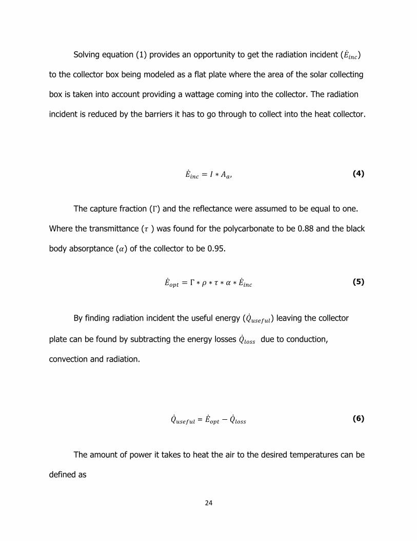
Solving equation (1) provides an opportunity to get the radiation incident (�̇�𝑖𝑛𝑐)
to the collector box being modeled as a flat plate where the area of the solar collecting
box is taken into account providing a wattage coming into the collector. The radiation
incident is reduced by the barriers it has to go through to collect into the heat collector.
�̇�𝑖𝑛𝑐 = 𝐼 ∗ 𝐴𝑎, (4)
The capture fraction (Γ) and the reflectance were assumed to be equal to one.
Where the transmittance (𝜏 ) was found for the polycarbonate to be 0.88 and the black
body absorptance (𝛼) of the collector to be 0.95.
�̇�𝑜𝑝𝑡 = Γ ∗ 𝜌 ∗ 𝜏 ∗ 𝛼 ∗ �̇�𝑖𝑛𝑐 (5)
By finding radiation incident the useful energy (�̇�𝑢𝑠𝑒𝑓𝑢𝑙) leaving the collector
plate can be found by subtracting the energy losses �̇�𝑙𝑜𝑠𝑠 due to conduction,
convection and radiation.
�̇�𝑢𝑠𝑒𝑓𝑢𝑙 = �̇�𝑜𝑝𝑡 − �̇�𝑙𝑜𝑠𝑠 (6)
The amount of power it takes to heat the air to the desired temperatures can be
defined as
25
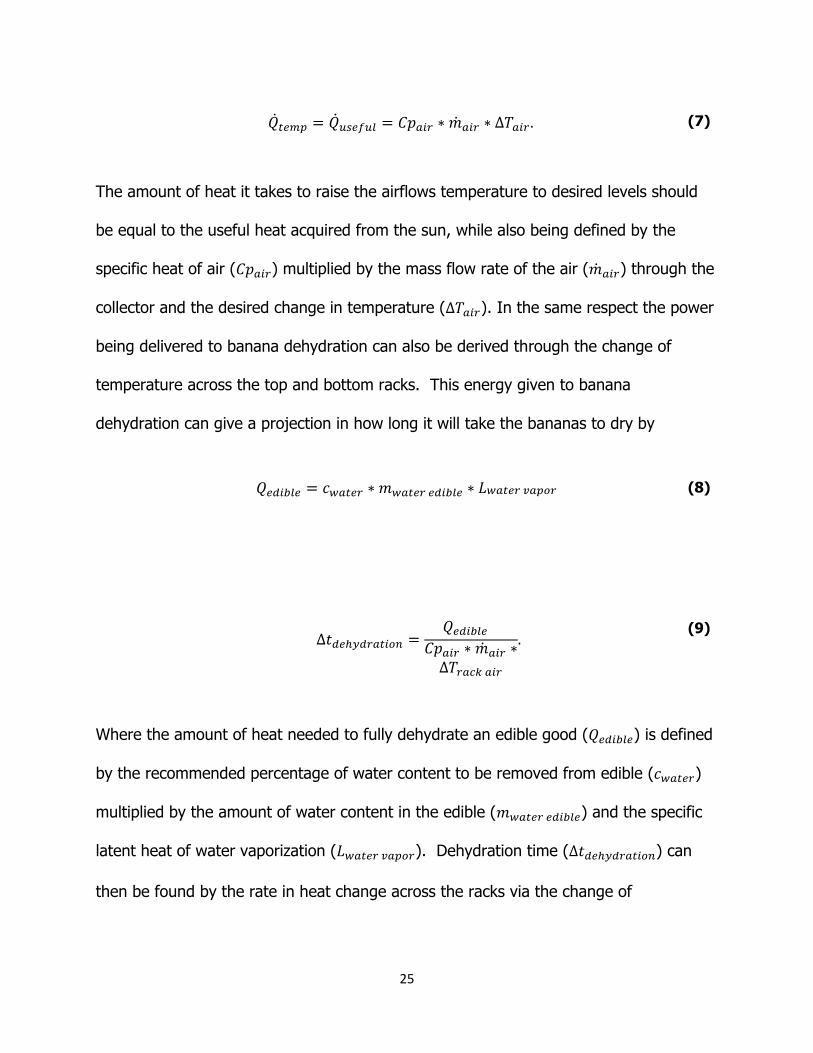
�̇�𝑡𝑒𝑚𝑝 = �̇�𝑢𝑠𝑒𝑓𝑢𝑙 = 𝐶𝑝𝑎𝑖𝑟 ∗ �̇�𝑎𝑖𝑟 ∗ Δ𝑇𝑎𝑖𝑟 . (7)
The amount of heat it takes to raise the airflows temperature to desired levels should
be equal to the useful heat acquired from the sun, while also being defined by the
specific heat of air (𝐶𝑝𝑎𝑖𝑟) multiplied by the mass flow rate of the air (�̇�𝑎𝑖𝑟) through the
collector and the desired change in temperature (Δ𝑇𝑎𝑖𝑟). In the same respect the power
being delivered to banana dehydration can also be derived through the change of
temperature across the top and bottom racks. This energy given to banana
dehydration can give a projection in how long it will take the bananas to dry by
𝑄𝑒𝑑𝑖𝑏𝑙𝑒 = 𝑐𝑤𝑎𝑡𝑒𝑟 ∗ 𝑚𝑤𝑎𝑡𝑒𝑟 𝑒𝑑𝑖𝑏𝑙𝑒 ∗ 𝐿𝑤𝑎𝑡𝑒𝑟 𝑣𝑎𝑝𝑜𝑟 (8)
Δ𝑡𝑑𝑒ℎ𝑦𝑑𝑟𝑎𝑡𝑖𝑜𝑛 =
𝑄𝑒𝑑𝑖𝑏𝑙𝑒
𝐶𝑝𝑎𝑖𝑟 ∗ �̇�𝑎𝑖𝑟 ∗Δ𝑇𝑟𝑎𝑐𝑘 𝑎𝑖𝑟
. (9)
Where the amount of heat needed to fully dehydrate an edible good (𝑄𝑒𝑑𝑖𝑏𝑙𝑒) is defined
by the recommended percentage of water content to be removed from edible (𝑐𝑤𝑎𝑡𝑒𝑟)
multiplied by the amount of water content in the edible (𝑚𝑤𝑎𝑡𝑒𝑟 𝑒𝑑𝑖𝑏𝑙𝑒) and the specific
latent heat of water vaporization (𝐿𝑤𝑎𝑡𝑒𝑟 𝑣𝑎𝑝𝑜𝑟). Dehydration time (Δ𝑡𝑑𝑒ℎ𝑦𝑑𝑟𝑎𝑡𝑖𝑜𝑛) can
then be found by the rate in heat change across the racks via the change of
26
temperature across the racks (Δ𝑇𝑟𝑎𝑐𝑘 𝑎𝑖𝑟) divided by the total energy needed to fully
dehydrate the edible.
These equations will be used later on to help in the calculation of the results and
discussion of the results.
27
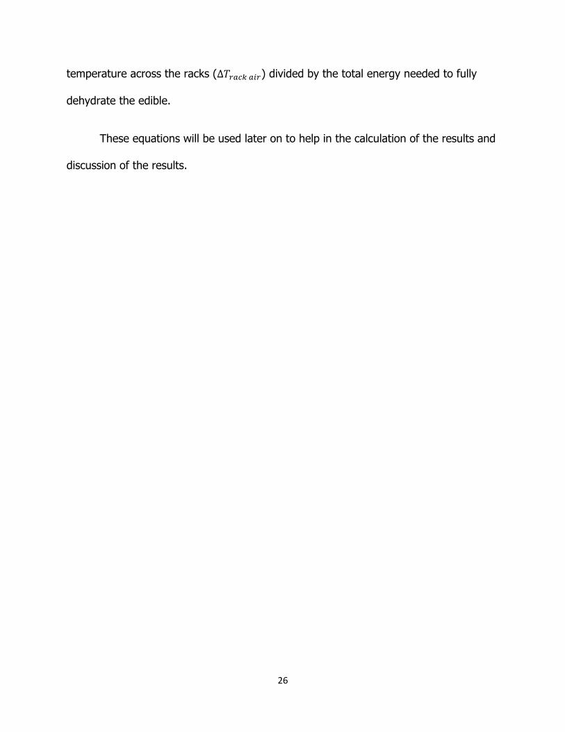
Best Design
Through a decision matrix it has been determined that the downdraft and
updraft solar dehydration designs are the designs most prevalent when it comes to
satisfying the main design parameters and therefore the specifications made by the
customer. This decision is illustrated in table 3 below.
Table 3. Design Parameters and Dehydrators Rankings
Design
Parameters Weighting
Conceptual Designs
Down
Draft
Up
Draft
S Air
Flow
Solar
Cabinet
Solar
Greenhouse
Cost 10 30 30 20 30 0
Function 10 30 30 30 10 30
Safety 9 25 18 18 27 18
Quality 7 21 21 14 7 14
Reliability 8 16 24 24 16 24
Operating
Instructions 5 15 15 15 10 15
Total 137 138 121 100 101
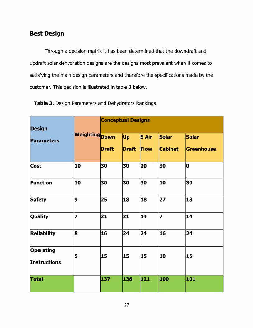
28
Knowing that the two designs needed to be tested, prototypes of both design were
created, they can be seen in figures 10 and 11 below.
Figure 10. Downdraft Prototype Figure 11. Updraft Prototype
Once the prototypes were completed, each of them were tested with plexiglas covering
the collector boxes and two 250 Watt heat lamps. Each dehydrator was tested with an
ambient room temperature of 19 degrees Celsius. The results of the tests are shown in
tables 4 and 5 below while a graph of those results is shown in figure 12 below.
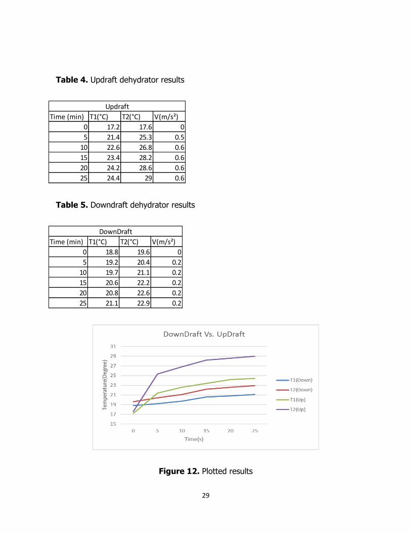
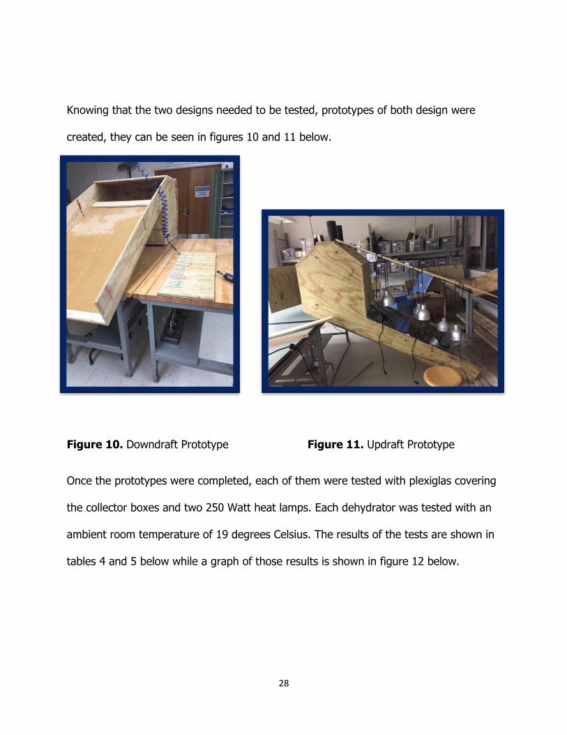
29
Table 4. Updraft dehydrator results
Table 5. Downdraft dehydrator results
Figure 12. Plotted results
Time (min) T1(°C) T2(°C) V(m/s²)
0 17.2 17.6 0
5 21.4 25.3 0.5
10 22.6 26.8 0.6
15 23.4 28.2 0.6
20 24.2 28.6 0.6
25 24.4 29 0.6
Updraft
Time (min) T1(°C) T2(°C) V(m/s²)
0 18.8 19.6 0
5 19.2 20.4 0.2
10 19.7 21.1 0.2
15 20.6 22.2 0.2
20 20.8 22.6 0.2
25 21.1 22.9 0.2
DownDraft

30
The temperatures measured for each dehydrator correlate as follows, temperature 1,
T1(Up), is the upper rack temperature and temperature 2, T2(up), is the lower rack
temperature in the updraft dehydrator drying chamber. For the downdraft dehydrator,
temperature 1, T1(down), corresponds to the lower rack and temperature 2, T2(down),
corresponds to the upper rack of the drying chamber. From these results, it was
determined that the updraft dehydrator was the better option as its temperature raised
faster and higher than the downdraft dehydrator. Another factor that made the updraft
dehydrator the better choice was the air flow velocity which can be seen in table 4 for
the updraft dehydrator and table 5 for the downdraft dehydrator; the air flow velocity
for the updraft dehydrator far outperformed the downdraft dehydrator and the better
the air flow velocity, the less mold growth on the dehydrated food.
31
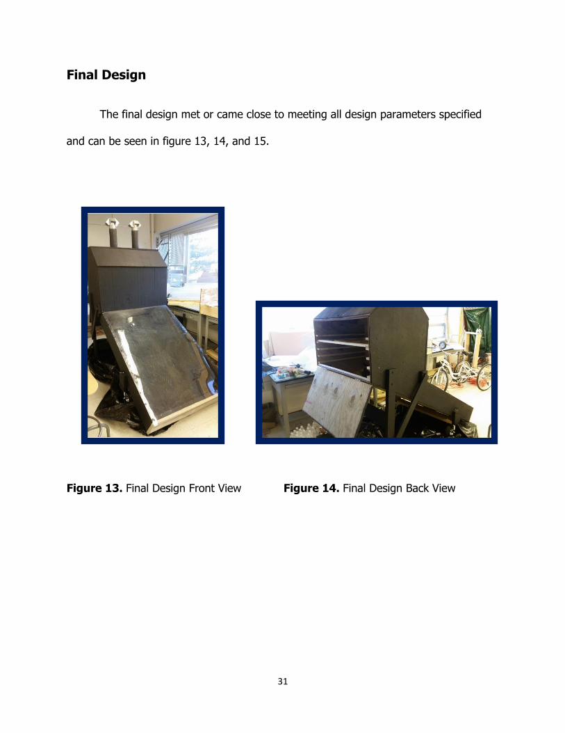
Final Design
The final design met or came close to meeting all design parameters specified
and can be seen in figure 13, 14, and 15.
Figure 13. Final Design Front View Figure 14. Final Design Back View
32
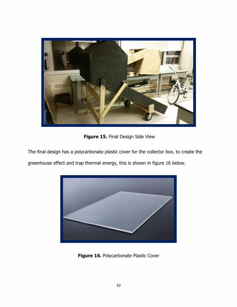
Figure 15. Final Design Side View
The final design has a polycarbonate plastic cover for the collector box, to create the
greenhouse effect and trap thermal energy, this is shown in figure 16 below.
Figure 16. Polycarbonate Plastic Cover

33
It has steel lath inside the collector box stretching from top to bottom and angled at 45
degrees to absorb solar radiation and provide heat to the air inside the collector box
through conduction, shown in figure 17 below.
Figure 17. Steel Lath
It has XPS insulation board inside the collecting box and drying chamber to keep the
heat from leaving the dehydrator. Water was used as the thermal capacity for the final
design to keep the drying chamber heated at night and prevent mold growth, the
thermal capacity can be seen in figure 18 below.

34
Figure 18. Water Bottles as Thermal Capacity
A door in the back for easy access to drying racks which can be reached without a
ladder! The final design has 5 molded polypropylene drying racks shown in figure 19
below.
Figure 19. Drying Rack
Adjustable vents are a key component in the final design and are located at the tops of
the chimneys. Adjustable vents are used for the increasing of the temperature in the

35
drying chamber (fully closed) and for the increasing of the air flow throughout the
drying chamber (fully open), they can be seen in figure 20 below.
Figure 20. Adjustable Vents
For the mobility of the final design, rotating wheels like on a shopping cart were place
on the front of the dehydrator. This is shown in figure 21 below.
Figure 21. Wheels for Mobility

36
Pest control included screens at the air intake and vent holes, these can be seen in
figures 22 and 23 below.
Figure 22. Air Intake Screen Figure 23. Vent Screen

37
Experimental Setup
Figure 24. Experimental Setup
Figure 24 above shows the experimental setup that was used to determine if the
final design would meet the customers design parameters. The room temperature was
72 degrees Fahrenheit. Eight heat lamps placed 6 inches above the polycarbonate
plastic cover of the collector box and directly orthogonal to the collector box were used
to simulate the solar radiation from the sun. Tests using an irradiance meter were
performed to determine whether or not eight heat lamps accurately represented the

38
suns solar radiation of the collector box. Results from those test are shown in figure 25
below.
Figure 25. Average Solar Irradiance provided from Eight Heat Lamps
It was found that eight 250 W heat lamps provided an average solar irradiance level of
842 W/m^2. The peak solar irradiance level in paynebar is 1000 W/m^2. The level of
solar irradience being produced by the test was within an acceptable range assuming
that panyebar would not be receiving its peak solar irradiance levels at all times of the

39
day. A thermocouple was used to measure the temperature at the bottom of the drying
chamber near the collector box and the temperature at the very top of the drying
chamber near the adjustable vents. An anemometer was used to take the air flow
velocities exiting the vents at the top of the drying chamber. Table 6 below shows the
two main experiments performed to determine whether the final design met customer
standards.
Table 6. Tests Performed
Test Bananas
(lbs) Tomatoes
(lbs) Total (lbs)
1 1.43 0.44 1.87
2 7 0 7
Test 1 had all the bananas and tomatoes on 1 drying rack, the second from the top
one, as shown in figure 26 below.
Figure 26. Experimental Setup for Test 1
40
Test 2 had the same experimental setup except the bananas were spread out on all five
drying racks.

41
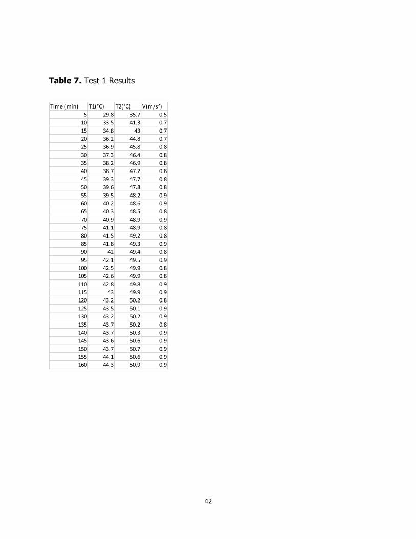
Updraft Data and Results
Dehydrated bananas and tomatoes were produced after only 8 hours (480 min)
for test 1. Data was collected in 5 min periods. Ambient temperature of the room was
22 °C while the air flow of the system initially started at 0.5 m/s and increased to a
maximum of 0.9 m/s. The following tables show the results of the test where T1
indicates the temperature of the lowest drying rack in the drying chamber and T2
indicates the temperature of the highest drying rack in the drying chamber. The velocity
recorded is the velocity of the air flow throughout the system measured with an
anemometer at the top of the chimney.
42
Table 7. Test 1 Results
Time (min) T1(°C) T2(°C) V(m/s²)
5 29.8 35.7 0.5
10 33.5 41.3 0.7
15 34.8 43 0.7
20 36.2 44.8 0.7
25 36.9 45.8 0.8
30 37.3 46.4 0.8
35 38.2 46.9 0.8
40 38.7 47.2 0.8
45 39.3 47.7 0.8
50 39.6 47.8 0.8
55 39.5 48.2 0.9
60 40.2 48.6 0.9
65 40.3 48.5 0.8
70 40.9 48.9 0.9
75 41.1 48.9 0.8
80 41.5 49.2 0.8
85 41.8 49.3 0.9
90 42 49.4 0.8
95 42.1 49.5 0.9
100 42.5 49.9 0.8
105 42.6 49.9 0.8
110 42.8 49.8 0.9
115 43 49.9 0.9
120 43.2 50.2 0.8
125 43.5 50.1 0.9
130 43.2 50.2 0.9
135 43.7 50.2 0.8
140 43.7 50.3 0.9
145 43.6 50.6 0.9
150 43.7 50.7 0.9
155 44.1 50.6 0.9
160 44.3 50.9 0.9

43
Table 8. Test 1 Results Cont.
Time (min) T1(°C) T2(°C) V(m/s²)
165 44.6 50.8 0.9
170 44.8 50.8 0.9
175 44.7 51 0.9
180 44.6 50.8 0.9
185 44.7 51.2 0.9
190 44.8 51.1 0.9
195 44.8 51.7 0.9
200 45.1 51.5 0.9
205 45 51.1 0.9
210 44.5 51 0.9
215 44.4 51 0.9
220 44.5 51.1 0.9
225 45 51.2 0.9
230 45.1 51.3 0.9
235 44.4 51.1 0.9
240 44.6 51.4 0.9
245 44.5 51.4 0.9
250 44.7 51.2 0.9
255 44.8 51.2 0.9
260 45.2 51.1 0.9
265 44.8 51 0.9
270 44.6 51 0.9
275 45.2 51.2 0.9
280 45.6 51.4 0.9
285 45.5 51.4 0.9
290 45.5 51.2 0.9
295 45.6 51.6 0.9
300 45.2 51.6 0.9
305 45.1 51.4 0.9
310 44.4 51.6 0.9
315 45.2 51.7 0.9
320 45.1 51.7 0.9
44
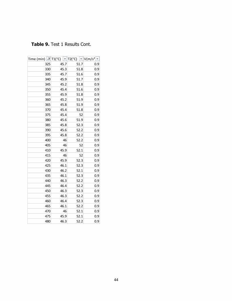
Table 9. Test 1 Results Cont.
Time (min) T1(°C) T2(°C) V(m/s²)
325 45.7 51.7 0.9
330 45.3 51.8 0.9
335 45.7 51.6 0.9
340 45.9 51.7 0.9
345 45.2 51.8 0.9
350 45.4 51.6 0.9
355 45.9 51.8 0.9
360 45.2 51.9 0.9
365 45.8 51.9 0.9
370 45.4 51.8 0.9
375 45.4 52 0.9
380 45.6 51.9 0.9
385 45.8 52.3 0.9
390 45.6 52.2 0.9
395 45.8 52.2 0.9
400 46 52.2 0.9
405 46 52 0.9
410 45.9 52.1 0.9
415 46 52 0.9
420 45.9 52.3 0.9
425 46.1 52.3 0.9
430 46.2 52.1 0.9
435 46.1 52.3 0.9
440 46.3 52.2 0.9
445 46.4 52.2 0.9
450 46.3 52.3 0.9
455 46.3 52.2 0.9
460 46.4 52.3 0.9
465 46.1 52.2 0.9
470 46 52.1 0.9
475 45.9 52.1 0.9
480 46.3 52.2 0.9
45
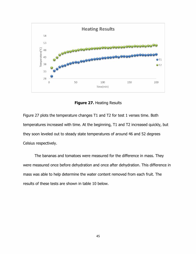
Figure 27. Heating Results
Figure 27 plots the temperature changes T1 and T2 for test 1 verses time. Both
temperatures increased with time. At the beginning, T1 and T2 increased quickly, but
they soon leveled out to steady state temperatures of around 46 and 52 degrees
Celsius respectively.
The bananas and tomatoes were measured for the difference in mass. They
were measured once before dehydration and once after dehydration. This difference in
mass was able to help determine the water content removed from each fruit. The
results of these tests are shown in table 10 below.

46
Table 10. Water Content of Dehydrated Fruit
Fruit Quantity
Raw
Weight
Dehydrated
Weight
Raw
Water
Weight
Water
Weight
Evaporated
Experimental
Water Content
Removal
Target
Water
Content
Removed Error
oz oz oz oz % % %
Bananas 6.000 22.875 6.125 17.056 4.567 73.2 74.6 1.794
Tomatoes 1.000 7.000 0.625 6.545 0.584 91.1 93.5 2.593
It was found that both bananas and tomatoes were in a reasonable range of water
content removal with only an error of 1.8% and 2.6% respectively.
Using the velocity data gathered, the mass flow rate of the air was found. With
the mass flow rate data equation (7), it was calculated the amount of heat needed to
be introduce into the air flow to get the desired temperature difference of around 30℃.

47
Figure 28. Heat Required vs. Mass Air Flow
By knowing the air flow rate an amount of heat addition of air was found and the
amount of heat lost was calculated using equation (6). The results can be seen in table
11 below.
Table 11. Heat Loss of System
Calculated
Heat in
(W)
mass air
flow
(kg/s)
Heat
Required
(W)
Heat
Loss
System
(W)
1026 0.018 542.7 483
0
0.005
0.01
0.015
0.02
0.025
0.03
0.035
0.04
0 200 400 600 800 1000 1200
Mas
ss A
ir F
low
(kg
/s)
Heat Required (W)
48
With the calculated radiation incident from equation (5) and an experimentally
calculated heat that was applied to the air from equation (7) the heat loss of the system
was derived to be 483 W.
After 8 hours heating, all the heat lamps were turned off in order to test the
temperature of the now heated up thermal capacity, water bottles, kept the system.
Table 12 below shows the results from those tests.
49
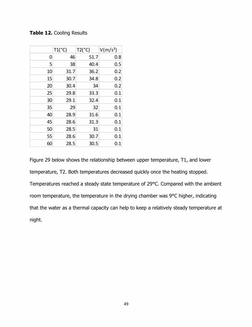
Table 12. Cooling Results
Figure 29 below shows the relationship between upper temperature, T1, and lower
temperature, T2. Both temperatures decreased quickly once the heating stopped.
Temperatures reached a steady state temperature of 29°C. Compared with the ambient
room temperature, the temperature in the drying chamber was 9°C higher, indicating
that the water as a thermal capacity can help to keep a relatively steady temperature at
night.
T1(°C) T2(°C) V(m/s²)
0 46 51.7 0.8
5 38 40.4 0.5
10 31.7 36.2 0.2
15 30.7 34.8 0.2
20 30.4 34 0.2
25 29.8 33.3 0.1
30 29.1 32.4 0.1
35 29 32 0.1
40 28.9 31.6 0.1
45 28.6 31.3 0.1
50 28.5 31 0.1
55 28.6 30.7 0.1
60 28.5 30.5 0.1

50
Figure 29. Cooling Results
The results for test 2 are very similar to the first results, the only notable
difference is that because of the added food and drying racks, the amount of time it
took to dehydrate all the fruits increased by 2 hours to 10 hours.
51
Discussion of Results
Through preliminary testing of the downdraft and updraft solar dehydrators it
was evident that the updraft model was more effective. The peak temperatures were
higher on both the top and bottom racks for the updraft than for the downdraft model.
This higher temperature was achieved despite the fact that the updraft had 3 times the
mass airflow, which is also an important component for food dehydration as it can
decrease the amount of mold on dehydrated fruit. Superior air flow and temperature
gain made the decision to move forward with the updraft prototype an easy one.
The desired temperature difference of at least 30 ℃ was achieved. The lower
rack temperature was higher than the upper rack which would suggest rack rotation
during the dehydration process to get uniform dehydration would be recommended.
The higher rack takes longer to reach dehydration temperatures and stagnates in the
lower ranges of dehydration temperatures. It is believed that having the dehydrator in
its natural environment with sun radiating on all surfaces of the dehydrator that both
the upper and lower rack temps will increase to higher temperatures within the
dehydration temperature ranges. The controlled ventilation of the chimneys with
dampers can also control the air flow and thus the temperature inside the drying
chamber. It is recommended to have a third chimney added to design in case flow
needs to be improved due to more heat addition from full surface radiation from sun.
After 8 hours of dehydration the measurements found that the fruit water
content was removed to almost perfectly specified levels for the ideal dehydration of
52
bananas and tomatoes. This verifies that the solar dehydrator is capable of reaching
water content levels for food to be dehydrated for food preservation.
Experimentally finding the airflow provided a way to calculate the amount of heat
that was being lost due to unwanted convection, conduction and radiation. 483 W were
being lost meaning that 47% of the energy coming into the collector was being lost. To
gain back some of these losses a more thorough job of insulation is encouraged with
better insulating characteristics for the materials used, and to do an in depth check for
any leaks in the system causing heat losses.
After the heat lamps were extinguished the air temperatures quickly diminished
inside the drying chamber. The water that was used as a thermal capacity and that was
heated over the heating period resulted in the drying chamber being 9 ℃ higher than
ambient room temperature after an hour. This temperature kept an air flow of 1 m/s.
This added heat and air flow during the course of non-sunlight hours will help deter
mold growth overnight. It would be recommended that the water heating test be done
over a longer period of time to see results over a full night period.
Depending on the user’s desire of involvement with dehydrator, it would be
recommended that the user take water out of drying chamber to absorb sunlight
outside of the chamber in the morning and upon nightfall the waters should be placed
back into the drying chamber. This would increase the efficiency of the dehydrator
during the dehydration period through the neglecting of having to heat not just the fruit

53
but also the water in the drying chamber. If the user decided to go with this option, it
is recommended to paint the water bottles black for maximum absorbance of sunlight.
In future experiments it is recommended that equation (9) be taken into
account. In order to do so the temperature difference of the drying racks has to be
recorded while they are bearing no fruit and then averaged. This average can then be
subtracted from the average of the fruit bearing racks experiment. The extra
temperature loss from the fruit bearing experiment then can be utilized for equation 9
in order to determine an accurate drying time.
54
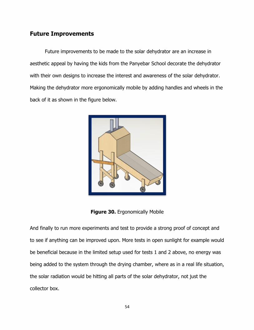
Future Improvements
Future improvements to be made to the solar dehydrator are an increase in
aesthetic appeal by having the kids from the Panyebar School decorate the dehydrator
with their own designs to increase the interest and awareness of the solar dehydrator.
Making the dehydrator more ergonomically mobile by adding handles and wheels in the
back of it as shown in the figure below.
Figure 30. Ergonomically Mobile
And finally to run more experiments and test to provide a strong proof of concept and
to see if anything can be improved upon. More tests in open sunlight for example would
be beneficial because in the limited setup used for tests 1 and 2 above, no energy was
being added to the system through the drying chamber, where as in a real life situation,
the solar radiation would be hitting all parts of the solar dehydrator, not just the
collector box.

55
Conclusion
Solar food dehydrators are used to preserve food by taking out the water
content of that food. It was determined that the updraft design preformed this task
very well, dehydrating bananas and tomatoes in 8 hours and 10 hours. There was no
mold growth on any of the dehydrated fruit. A thermal capacity was added to prevent
mold growth overnight on the food, it was determined that the thermal capacity was
able to keep the steady state temperature inside the solar dehydrator higher than the
ambient room temperature resulting in a constant air flow throughout the system which
is needed to prevent mold growth. The updraft food dehydrator meet all customer
specifications and is ready to be implemented in Panyebar, Guatemala where it can be
put to use feeding the local population and making them a profit. “These days there is a
lot of poverty in the world, and that’s a scandal when we have so many riches and
resources to give to everyone.” (Pope Francis) This solar food dehydrator tries to
accomplish this goal and hopefully it can be implemented around the world, not just
Guatemala, as the instructions on how to manufacture it will be posted online for the
world to see!