floor standing indoor unit engineering manual
TRANSCRIPT
FLOOR STANDING INDOOR UNIT ENGINEERING MANUAL
7,500 to 24,200 Btu/h
Cased Uncased
For continual product development, LG Electronics U.S.A., Inc. reserves the right to change specifications without notice. © LG Electronics U.S.A., Inc.
PROPRIETARY DATA NOTICEThis document, as well as all reports, illustrations, data, information,
and other materials are the property of LG Electronics U.S.A., Inc., and are disclosed by LG Electronics U.S.A., Inc. only in confidence.
This document is for design purposes only.
A summary list of safety precautions is on page 3.
For more technical materials such as submittals, catalogs, installation, owner’s, and service manuals, visit www.lghvac.com.
INTRODUCTION | 3
Introduction
Due to our policy of continuous product innovation, some specifications may change without notification. © LG Electronics U.S.A., Inc., Englewood Cliffs, NJ. All rights reserved. “LG” is a registered trademark of LG Corp.
TABLE OF CONTENTS
Unit Nomenclature ���������������������������������������������������������������������������������������������������������������������������������������������������������������������������������������������������������� 4
LATS Overview ������������������������������������������������������������������������������������������������������������������������������������������������������������������������������������������������������������ 5-6
Refrigerant Charge Worksheets ��������������������������������������������������������������������������������������������������������������������������������������������������������������������������������� 7-9
Floor Standing Indoor Units ����������������������������������������������������������������������������������������������������������������������������������������������������������������������������������� 10-36Mechanical Specifications ������������������������������������������������������������������������������������������������������������������������������������������������������������������������������������� 11-12General Data ��������������������������������������������������������������������������������������������������������������������������������������������������������������������������������������������������������� 13-14Electrical Data ������������������������������������������������������������������������������������������������������������������������������������������������������������������������������������������������������������ 15External Dimensions ���������������������������������������������������������������������������������������������������������������������������������������������������������������������������������������������� 16-17Electrical Wiring Diagram �������������������������������������������������������������������������������������������������������������������������������������������������������������������������������������� 18-19Refrigerant Flow Diagram ������������������������������������������������������������������������������������������������������������������������������������������������������������������������������������������� 20External Static Pressure and Air Flow ������������������������������������������������������������������������������������������������������������������������������������������������������������������������ 21Acoustic Data �������������������������������������������������������������������������������������������������������������������������������������������������������������������������������������������������������� 22-24Air Velocity / Temperature Distribution ������������������������������������������������������������������������������������������������������������������������������������������������������������������� 25-27Capacity Tables ����������������������������������������������������������������������������������������������������������������������������������������������������������������������������������������������������� 28-36
Application Guidelines �������������������������������������������������������������������������������������������������������������������������������������������������������������������������������������������� 37-42Selecting the Best Location ���������������������������������������������������������������������������������������������������������������������������������������������������������������������������������������� 38General Mounting ������������������������������������������������������������������������������������������������������������������������������������������������������������������������������������������������������� 39General Drain Piping Information ������������������������������������������������������������������������������������������������������������������������������������������������������������������������������� 39Wiring Guidelines �������������������������������������������������������������������������������������������������������������������������������������������������������������������������������������������������� 41-42Wired Remote Controller Location ����������������������������������������������������������������������������������������������������������������������������������������������������������������������������� 42
Acronyms ���������������������������������������������������������������������������������������������������������������������������������������������������������������������������������������������������������������������� 43
TABLE OF SYMBOLSThis symbol indicates an imminently hazardous situation which, if not avoided, will result in death or serious injury.
This symbol indicates a potentially hazardous situation which, if not avoided, could result in death or serious injury.
This symbol indicates a potentially hazardous situation which, if not avoided, may result in minor or moderate injury.
This symbol indicates situations that may result in equipment or property damage accidents only.
This symbol indicates an action should not be completed.
DANGER
CAUTION
4 | INTRODUCTIONDue to our policy of continuous product innovation, some specifications may change without notification. © LG Electronics U.S.A., Inc., Englewood Cliffs, NJ. All rights reserved. “LG” is a registered trademark of LG Corp.
MUL
TI V
Flo
or S
tand
ing
Indo
or U
nit E
ngin
eerin
g M
anua
l
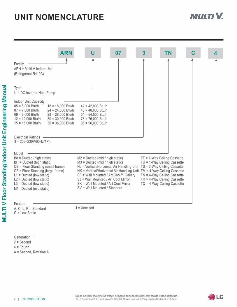
ARN U 07 3 TN C
Generation2 = Second4 = FourthA = Second, Revision A
Electrical Ratings 3 = 208–230V/60Hz/1Ph
05 = 5,000 Btu/h 07 = 7,000 Btu/h 09 = 9,000 Btu/h 12 = 12,000 Btu/h 15 = 15,000 Btu/h
18 = 18,000 Btu/h 24 = 24,000 Btu/h 28 = 28,000 Btu/h 30 = 30,000 Btu/h 36 = 36,000 Btu/h
42 = 42,000 Btu/h 48 = 48,000 Btu/h 54 = 54,000 Btu/h 76 = 76,000 Btu/h 96 = 96,000 Btu/h
TypeU = DC Inverter Heat Pump
FamilyARN = Multi V Indoor Unit(Refrigerant R410A)
B8 = Ducted (high static) BH = Ducted (high static) CE = Floor Standing (small frame) CF = Floor Standing (large frame) L1 = Ducted (low static) L2 = Ducted (low static) L3 = Ducted (low static)M1 =Ducted (mid static)
M2 = Ducted (mid / high static) M3 = Ducted (mid / high static) NJ = Vertical/Horizontal Air Handling Unit NK = Vertical/Horizontal Air Handling Unit SF = Wall Mounted / Art Cool™ Gallery SJ = Wall Mounted / Art Cool Mirror SK = Wall Mounted / Art Cool Mirror SV = Wall Mounted / Standard
TT = 1-Way Ceiling Cassette TU = 1-Way Ceiling Cassette TS = 2-Way Ceiling Cassette TM = 4-Way Ceiling Cassette TN = 4-Way Ceiling Cassette TR = 4-Way Ceiling Cassette TQ = 4-Way Ceiling Cassette
FeatureA, C, L, R = Standard G = Low Static
U = Uncased
Indoor Unit Capacity
Model
4
UNIT NOMENCLATURE
INTRODUCTION | 5
Introduction
Due to our policy of continuous product innovation, some specifications may change without notification. © LG Electronics U.S.A., Inc., Englewood Cliffs, NJ. All rights reserved. “LG” is a registered trademark of LG Corp.
LG Air Conditioner Technical Solution (LATS) SoftwareA properly designed and installed refrigerant piping system is critical to the optimal performance of LG air-conditioning systems. To assist engineers, LG offers, free of charge, LG Air Conditioner Technical Solution (LATS) software—a total design solution for LG air conditioning systems.
To reduce the risk of designing an improper applied system or one that will not operate correctly, LG requires that LATS software be used on all projects.
FormatsLATS is available to LG customers in three user interfaces: LATS HVAC, LATS CAD2, and LATS REVIT. All three LATS formats are available through www.myLGHVAC.com, or contact an LG Sales Representative.
LATS HVAC is a Windows®-based application that aids engineers in designing LG Variable Refrigerant Flow (VRF), Multi F / Multi F MAX, Single-Zone, and Energy Recovery Ventilator (ERV) systems.*Windows® is a registered mark of Microsoft® Corporation.
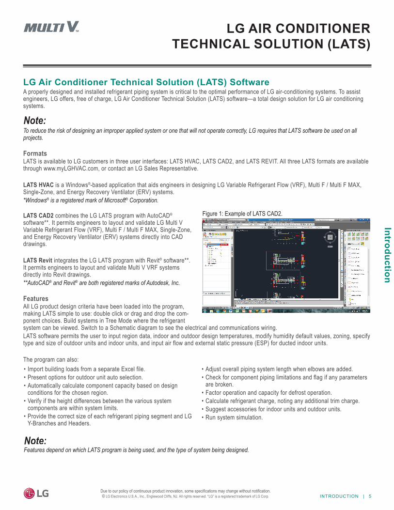
LATS CAD2 combines the LG LATS program with AutoCAD® software**. It permits engineers to layout and validate LG Multi V Variable Refrigerant Flow (VRF), Multi F / Multi F MAX, Single-Zone, and Energy Recovery Ventilator (ERV) systems directly into CAD drawings.
LATS Revit integrates the LG LATS program with Revit® software**. It permits engineers to layout and validate Multi V VRF systems directly into Revit drawings.**AutoCAD® and Revit® are both registered marks of Autodesk, Inc.
FeaturesAll LG product design criteria have been loaded into the program, making LATS simple to use: double click or drag and drop the com-ponent choices. Build systems in Tree Mode where the refrigerant system can be viewed. Switch to a Schematic diagram to see the electrical and communications wiring.LATS software permits the user to input region data, indoor and outdoor design temperatures, modify humidity default values, zoning, specify type and size of outdoor units and indoor units, and input air flow and external static pressure (ESP) for ducted indoor units.
The program can also:
LG AIR CONDITIONER TECHNICAL SOLUTION (LATS)
• Import building loads from a separate Excel file.• Present options for outdoor unit auto selection.• Automatically calculate component capacity based on design
conditions for the chosen region.• Verify if the height differences between the various system
components are within system limits.• Provide the correct size of each refrigerant piping segment and LG
Y-Branches and Headers.
• Adjust overall piping system length when elbows are added.• Check for component piping limitations and flag if any parameters
are broken.• Factor operation and capacity for defrost operation.• Calculate refrigerant charge, noting any additional trim charge.• Suggest accessories for indoor units and outdoor units.• Run system simulation.
Features depend on which LATS program is being used, and the type of system being designed.
Figure 1: Example of LATS CAD2.
6 | INTRODUCTIONDue to our policy of continuous product innovation, some specifications may change without notification. © LG Electronics U.S.A., Inc., Englewood Cliffs, NJ. All rights reserved. “LG” is a registered trademark of LG Corp.
MUL
TI V
Flo
or S
tand
ing
Indo
or U
nit E
ngin
eerin
g M
anua
l
LATS Generates a Complete Project ReportLATS software also generates a report containing project design parameters, cooling and heating design data, system component perfor-mance, and capacity data. The report includes system combination ratio and refrigerant charge calculations; and provides detailed bill of material, including outdoor units, indoor units, control devices, accessories, refrigerant pipe sizes segregated by building, by system, by pipe size, and by pipe segments. LATS can generate an Excel GERP report that can imported into the LG SOPS pricing and ordering system.
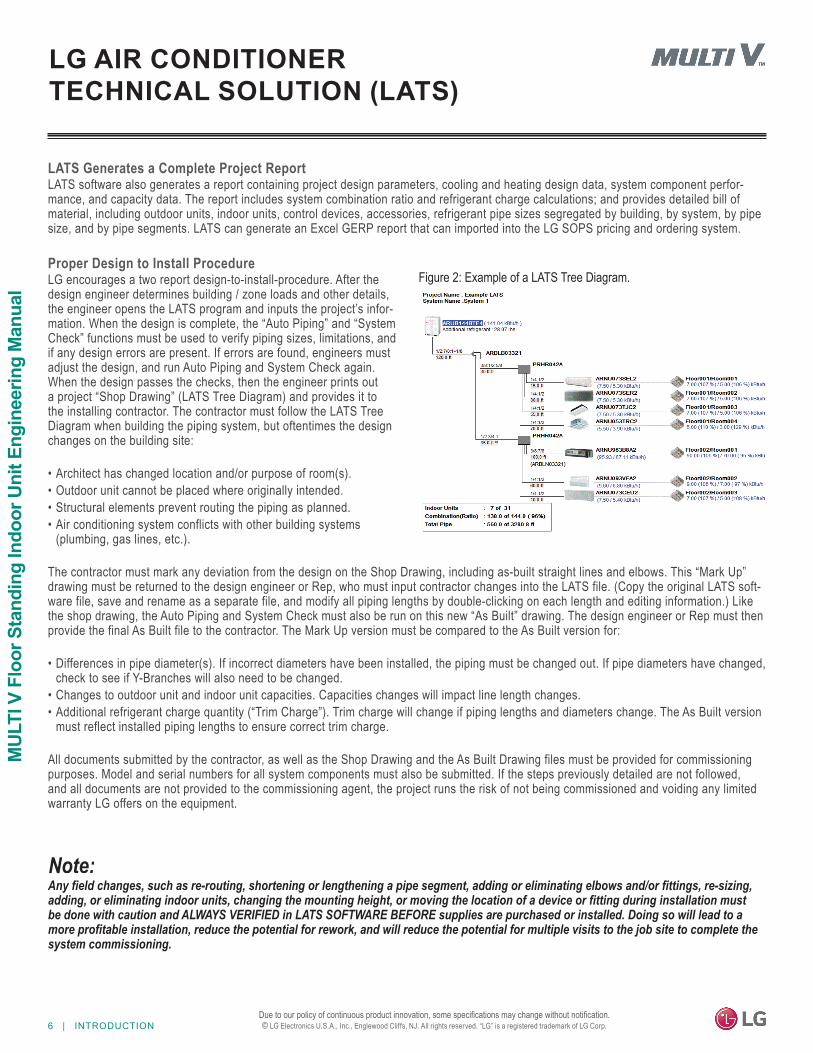
Proper Design to Install ProcedureLG encourages a two report design-to-install-procedure. After the design engineer determines building / zone loads and other details, the engineer opens the LATS program and inputs the project’s infor-mation. When the design is complete, the “Auto Piping” and “System Check” functions must be used to verify piping sizes, limitations, and if any design errors are present. If errors are found, engineers must adjust the design, and run Auto Piping and System Check again. When the design passes the checks, then the engineer prints out a project “Shop Drawing” (LATS Tree Diagram) and provides it to the installing contractor. The contractor must follow the LATS Tree Diagram when building the piping system, but oftentimes the design changes on the building site:
• Architect has changed location and/or purpose of room(s).• Outdoor unit cannot be placed where originally intended.• Structural elements prevent routing the piping as planned.• Air conditioning system conflicts with other building systems
(plumbing, gas lines, etc.).
The contractor must mark any deviation from the design on the Shop Drawing, including as-built straight lines and elbows. This “Mark Up” drawing must be returned to the design engineer or Rep, who must input contractor changes into the LATS file. (Copy the original LATS soft-ware file, save and rename as a separate file, and modify all piping lengths by double-clicking on each length and editing information.) Like the shop drawing, the Auto Piping and System Check must also be run on this new “As Built” drawing. The design engineer or Rep must then provide the final As Built file to the contractor. The Mark Up version must be compared to the As Built version for:
• Differences in pipe diameter(s). If incorrect diameters have been installed, the piping must be changed out. If pipe diameters have changed,check to see if Y-Branches will also need to be changed.
• Changes to outdoor unit and indoor unit capacities. Capacities changes will impact line length changes.• Additional refrigerant charge quantity (“Trim Charge”). Trim charge will change if piping lengths and diameters change. The As Built version
must reflect installed piping lengths to ensure correct trim charge.
All documents submitted by the contractor, as well as the Shop Drawing and the As Built Drawing files must be provided for commissioning purposes. Model and serial numbers for all system components must also be submitted. If the steps previously detailed are not followed, and all documents are not provided to the commissioning agent, the project runs the risk of not being commissioned and voiding any limited warranty LG offers on the equipment.
LG AIR CONDITIONER TECHNICAL SOLUTION (LATS)
Figure 2: Example of a LATS Tree Diagram.
Any field changes, such as re-routing, shortening or lengthening a pipe segment, adding or eliminating elbows and/or fittings, re-sizing, adding, or eliminating indoor units, changing the mounting height, or moving the location of a device or fitting during installation must be done with caution and ALWAYS VERIFIED in LATS SOFTWARE BEFORE supplies are purchased or installed. Doing so will lead to a more profitable installation, reduce the potential for rework, and will reduce the potential for multiple visits to the job site to complete the system commissioning.
INTRODUCTION | 7
Introduction
Due to our policy of continuous product innovation, some specifications may change without notification. © LG Electronics U.S.A., Inc., Englewood Cliffs, NJ. All rights reserved. “LG” is a registered trademark of LG Corp.
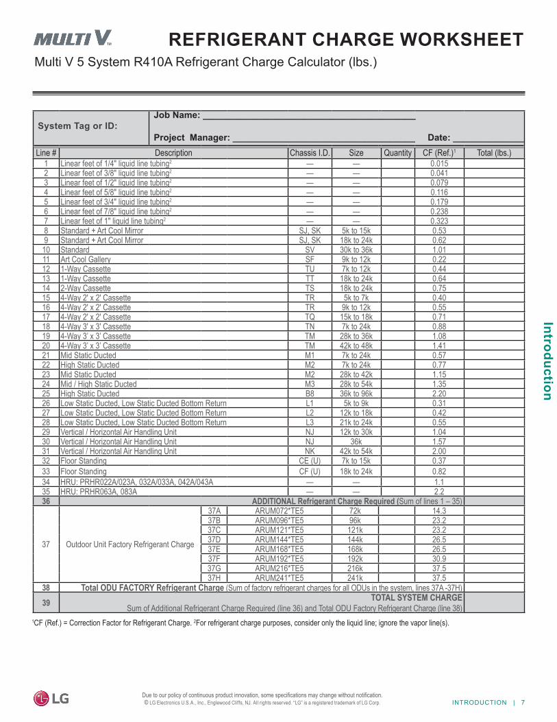
Multi V 5 System R410A Refrigerant Charge Calculator (lbs.)REFRIGERANT CHARGE WORKSHEET
1CF (Ref.) = Correction Factor for Refrigerant Charge. 2For refrigerant charge purposes, consider only the liquid line; ignore the vapor line(s).
System Tag or ID:Job Name: __________________________________________
Project Manager: ____________________________________ Date: ______________Line # Description Chassis I.D. Size Quantity CF (Ref.)1 Total (lbs.)
1 Linear feet of 1/4" liquid line tubing2 — — 0.0152 Linear feet of 3/8" liquid line tubing2 — — 0.0413 Linear feet of 1/2" liquid line tubing2 — — 0.0794 Linear feet of 5/8" liquid line tubing2 — — 0.1165 Linear feet of 3/4" liquid line tubing2 — — 0.1796 Linear feet of 7/8" liquid line tubing2 — — 0.2387 Linear feet of 1" liquid line tubing2 — — 0.3238 Standard + Art Cool Mirror SJ, SK 5k to 15k 0.539 Standard + Art Cool Mirror SJ, SK 18k to 24k 0.62
10 Standard SV 30k to 36k 1.0111 Art Cool Gallery SF 9k to 12k 0.2212 1-Way Cassette TU 7k to 12k 0.4413 1-Way Cassette TT 18k to 24k 0.6414 2-Way Cassette TS 18k to 24k 0.7515 4-Way 2' x 2' Cassette TR 5k to 7k 0.4016 4-Way 2' x 2' Cassette TR 9k to 12k 0.5517 4-Way 2' x 2' Cassette TQ 15k to 18k 0.7118 4-Way 3' x 3' Cassette TN 7k to 24k 0.8819 4-Way 3’ x 3’ Cassette TM 28k to 36k 1.0820 4-Way 3’ x 3’ Cassette TM 42k to 48k 1.4121 Mid Static Ducted M1 7k to 24k 0.5722 High Static Ducted M2 7k to 24k 0.7723 Mid Static Ducted M2 28k to 42k 1.1524 Mid / High Static Ducted M3 28k to 54k 1.3525 High Static Ducted B8 36k to 96k 2.2026 Low Static Ducted, Low Static Ducted Bottom Return L1 5k to 9k 0.3127 Low Static Ducted, Low Static Ducted Bottom Return L2 12k to 18k 0.4228 Low Static Ducted, Low Static Ducted Bottom Return L3 21k to 24k 0.5529 Vertical / Horizontal Air Handling Unit NJ 12k to 30k 1.0430 Vertical / Horizontal Air Handling Unit NJ 36k 1.5731 Vertical / Horizontal Air Handling Unit NK 42k to 54k 2.0032 Floor Standing CE (U) 7k to 15k 0.3733 Floor Standing CF (U) 18k to 24k 0.8234 HRU: PRHR022A/023A, 032A/033A, 042A/043A — — 1.135 HRU: PRHR063A, 083A — — 2.236 ADDITIONAL Refrigerant Charge Required (Sum of lines 1 – 35)
37 Outdoor Unit Factory Refrigerant Charge
37A ARUM072*TE5 72k 14.337B ARUM096*TE5 96k 23.237C ARUM121*TE5 121k 23.237D ARUM144*TE5 144k 26.537E ARUM168*TE5 168k 26.537F ARUM192*TE5 192k 30.937G ARUM216*TE5 216k 37.537H ARUM241*TE5 241k 37.5
38 Total ODU FACTORY Refrigerant Charge (Sum of factory refrigerant charges for all ODUs in the system, lines 37A -37H) 39 TOTAL SYSTEM CHARGE
Sum of Additional Refrigerant Charge Required (line 36) and Total ODU Factory Refrigerant Charge (line 38)
8 | INTRODUCTIONDue to our policy of continuous product innovation, some specifications may change without notification. © LG Electronics U.S.A., Inc., Englewood Cliffs, NJ. All rights reserved. “LG” is a registered trademark of LG Corp.
MUL
TI V
Flo
or S
tand
ing
Indo
or U
nit E
ngin
eerin
g M
anua
l
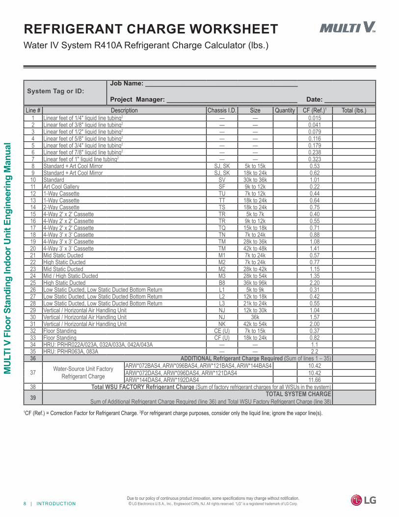
Water IV System R410A Refrigerant Charge Calculator (lbs.)REFRIGERANT CHARGE WORKSHEET
1CF (Ref.) = Correction Factor for Refrigerant Charge. 2For refrigerant charge purposes, consider only the liquid line; ignore the vapor line(s).
System Tag or ID:Job Name: __________________________________________
Project Manager: ____________________________________ Date: ______________Line # Description Chassis I.D. Size Quantity CF (Ref.)1 Total (lbs.)
1 Linear feet of 1/4" liquid line tubing2 — — 0.0152 Linear feet of 3/8" liquid line tubing2 — — 0.0413 Linear feet of 1/2" liquid line tubing2 — — 0.0794 Linear feet of 5/8" liquid line tubing2 — — 0.1165 Linear feet of 3/4" liquid line tubing2 — — 0.1796 Linear feet of 7/8" liquid line tubing2 — — 0.2387 Linear feet of 1" liquid line tubing2 — — 0.3238 Standard + Art Cool Mirror SJ, SK 5k to 15k 0.539 Standard + Art Cool Mirror SJ, SK 18k to 24k 0.62
10 Standard SV 30k to 36k 1.0111 Art Cool Gallery SF 9k to 12k 0.2212 1-Way Cassette TU 7k to 12k 0.4413 1-Way Cassette TT 18k to 24k 0.6414 2-Way Cassette TS 18k to 24k 0.7515 4-Way 2' x 2' Cassette TR 5k to 7k 0.4016 4-Way 2' x 2' Cassette TR 9k to 12k 0.5517 4-Way 2' x 2' Cassette TQ 15k to 18k 0.7118 4-Way 3' x 3' Cassette TN 7k to 24k 0.8819 4-Way 3' x 3' Cassette TM 28k to 36k 1.0820 4-Way 3’ x 3’ Cassette TM 42k to 48k 1.4121 Mid Static Ducted M1 7k to 24k 0.5722 High Static Ducted M2 7k to 24k 0.7723 Mid Static Ducted M2 28k to 42k 1.1524 Mid / High Static Ducted M3 28k to 54k 1.3525 High Static Ducted B8 36k to 96k 2.2026 Low Static Ducted, Low Static Ducted Bottom Return L1 5k to 9k 0.3127 Low Static Ducted, Low Static Ducted Bottom Return L2 12k to 18k 0.4228 Low Static Ducted, Low Static Ducted Bottom Return L3 21k to 24k 0.5529 Vertical / Horizontal Air Handling Unit NJ 12k to 30k 1.0430 Vertical / Horizontal Air Handling Unit NJ 36k 1.5731 Vertical / Horizontal Air Handling Unit NK 42k to 54k 2.0032 Floor Standing CE (U) 7k to 15k 0.3733 Floor Standing CF (U) 18k to 24k 0.8234 HRU: PRHR022A/023A, 032A/033A, 042A/043A — — 1.135 HRU: PRHR063A, 083A — — 2.236 ADDITIONAL Refrigerant Charge Required (Sum of lines 1 – 35)
37 Water-Source Unit FactoryRefrigerant Charge
ARW*072BAS4, ARW*096BAS4, ARW*121BAS4, ARW*144BAS4 10.42ARW*072DAS4, ARW*096DAS4, ARW*121DAS4 10.42ARW*144DAS4, ARW*192DAS4 11.66
38 Total WSU FACTORY Refrigerant Charge (Sum of factory refrigerant charges for all WSUs in the system) 39 TOTAL SYSTEM CHARGE
Sum of Additional Refrigerant Charge Required (line 36) and Total WSU Factory Refrigerant Charge (line 38)
INTRODUCTION | 9
Introduction
Due to our policy of continuous product innovation, some specifications may change without notification. © LG Electronics U.S.A., Inc., Englewood Cliffs, NJ. All rights reserved. “LG” is a registered trademark of LG Corp.
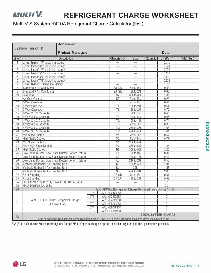
Multi V S System R410A Refrigerant Charge Calculator (lbs.)REFRIGERANT CHARGE WORKSHEET
1CF (Ref.) = Correction Factor for Refrigerant Charge. 2For refrigerant charge purposes, consider only the liquid line; ignore the vapor line(s).
System Tag or ID:Job Name: __________________________________________
Project Manager: ____________________________________ Date: ______________Line # Description Chassis I.D. Size Quantity CF (Ref.)1 Total (lbs.)
1 Linear feet of 1/4" liquid line tubing2 — — 0.0152 Linear feet of 3/8" liquid line tubing2 — — 0.0413 Linear feet of 1/2" liquid line tubing2 — — 0.0794 Linear feet of 5/8" liquid line tubing2 — — 0.1165 Linear feet of 3/4" liquid line tubing2 — — 0.1796 Linear feet of 7/8" liquid line tubing2 — — 0.2387 Linear feet of 1" liquid line tubing2 — — 0.3238 Standard + Art Cool Mirror SJ, SK 5k to 15k 0.539 Standard + Art Cool Mirror SJ, SK 18k to 24k 0.62
10 Standard SV 30k to 36k 1.0111 Art Cool Gallery SF 9k to 12k 0.2212 1-Way Cassette TU 7k to 12k 0.4413 1-Way Cassette TT 18k to 24k 0.6414 2-Way Cassette TS 18k to 24k 0.7515 4-Way 2' x 2' Cassette TR 5k to 7k 0.4016 4-Way 2' x 2' Cassette TR 9k to 12k 0.5517 4-Way 2' x 2' Cassette TQ 15k to 18k 0.7118 4-Way 3' x 3' Cassette TN 7k to 24k 0.8819 4-Way 3' x 3' Cassette TM 28k to 36k 1.0820 4-Way 3’ x 3’ Cassette TM 42k to 48k 1.4121 Mid Static Ducted M1 7k to 24k 0.5722 High Static Ducted M2 7k to 24k 0.7723 Mid Static Ducted M2 28k to 42k 1.1524 Mid / High Static Ducted M3 28k to 54k 1.3525 High Static Ducted B8 36k to 96k 2.2026 Low Static Ducted, Low Static Ducted Bottom Return L1 5k to 9k 0.3127 Low Static Ducted, Low Static Ducted Bottom Return L2 12k to 18k 0.4228 Low Static Ducted, Low Static Ducted Bottom Return L3 21k to 24k 0.5529 Vertical / Horizontal Air Handling Unit NJ 12k to 30k 1.0430 Vertical / Horizontal Air Handling Unit NJ 36k 1.5731 Vertical / Horizontal Air Handling Unit NK 42k to 54k 2.0032 Floor Standing CE (U) 7k to 15k 0.3733 Floor Standing CF (U) 18k to 24k 0.8234 HRU: PRHR022A/023A, 032A/ 033A, 042A/ 043A — — 1.135 HRU: PRHR063A, 083A — — 2.236 ADDITIONAL Refrigerant Charge Required (Sum of lines 1 – 35)
37 Total ODU FACTORY Refrigerant Charge (Choose One)
37A ARUN024GSS4 037B ARUN038GSS4 037C ARUN048GSS4 037D ARUN053GSS4 037F ARUN060GSS4 037G ARUB060GSS4 0
38 TOTAL SYSTEM CHARGE Sum of Additional Refrigerant Charge Required (line 36) and ODU Factory Refrigerant Charge (from lines 37A through 37G)

PRODUCT DATA
Cased
Uncased
Mechanical Specifications on page 11General Data on page 13Electrical Data on page 15External Dimensions on page 16Electrical Wiring Diagram on page 18Refrigerant Flow Diagram on page 20External Static Pressure and Air Flow on page 21Acoustic Data on page 22Air Velocity / Temperature Distribution on page 25Capacity Tables on page 28
PRODUCT DATA | 11
Product Data
Due to our policy of continuous product innovation, some specifications may change without notification. © LG Electronics U.S.A., Inc., Englewood Cliffs, NJ. All rights reserved. “LG” is a registered trademark of LG Corp.
PRODUCT DATAMechanical Specifications
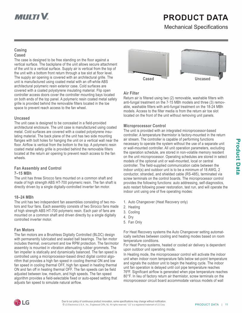
Casing CasedThe case is designed to be free standing on the floor against a vertical surface. The backplane of the unit allows secure attachment of the unit to a vertical surface. Supply air is vertical from the top of the unit with a bottom front return through a toe slot at floor level. The supply air opening is covered with an architectural grille. The unit is manufactured using coated metal with an off-white ABS architectural polymeric resin exterior case. Cold surfaces are covered with a coated polystyrene insulating material. Flip open controller access doors cover the controller mounting bays located on both ends of the top panel. A polymeric resin coated metal safety grille is provided behind the removable filters located in the toe space to prevent reach access to the fan wheel.
UncasedThe unit case is designed to be concealed in a field-provided architectural enclosure. The unit case is manufactured using coated metal. Cold surfaces are covered with a coated polystyrene insu-lating material. The back plane of the unit has two side mounting flanges with bolt holes for hanging the unit on a vertical wall near the floor. Airflow is vertical from the bottom to the top. A polymeric resin coated metal safety grille is provided behind the removable filters located at the return air opening to prevent reach access to the fan wheels.
Fan Assembly and Control7–15 MBhThe unit has three Sirocco fans mounted on a common shaft and made of high strength ABS HT-700 polymeric resin. The fan shaft is directly driven by a single digitally-controlled inverter fan motor.
18–24 MBhThe unit has two independent fan assemblies consisting of two mo-tors and four fans. Each assembly consists of two Sirocco fans made of high strength ABS HT-700 polymeric resin. Each pair of fans are mounted on a common shaft and driven directly by a single digitally controlled inverter motor.
Fan MotorsThe fan motors are a Brushless Digitally Controlled (BLDC) design with permanently lubricated and sealed ball bearings. The fan motor includes thermal, overcurrent and low RPM protection. The fan/motor assembly is mounted in vibration attenuating rubber grommets. The fan impeller is statically and dynamically balanced. The fan speed is controlled using a microprocessor-based direct digital control algo-rithm that provides a high fan speed in cooling thermal ON and low fan speed in cooling thermal OFF, high fan speed in heating thermal ON and fan off in heating thermal OFF. The fan speeds can be field adjusted between low, medium, and high speeds. The fan speed algorithm provides a field-selectable fixed or auto-speed setting that adjusts fan speed to simulate natural airflow.
Air FilterReturn air is filtered using two (2) removable, washable filters with anti-fungal treatment on the 7-15 MBh models and three (3) remov-able, washable filters with anti-fungal treatment on the 18-24 MBh models. Access to the filter media is from the return air toe slot located on the front of the unit without removing unit panels.
Microprocessor ControlThe unit is provided with an integrated microprocessor-based controller. A temperature thermistor is factory-mounted in the return air stream. The controller is capable of performing functions necessary to operate the system without the use of a separate unit or wall-mounted controller. All unit operation parameters, excluding the operation schedule, are stored in non-volatile memory resident on the unit microprocessor. Operating schedules are stored in select models of the optional unit or wall-mounted, local or central controller. The field-supplied communication cable between the indoor unit(s) and outdoor unit is to be a minimum of 18 AWG, 2 conductor, stranded, and shielded cable (RS-485), terminated via screw terminals on the control boards. The microprocessor control provides the following functions: auto addressing, self-diagnostics, auto restart following power restoration, test run, and will operate the indoor unit using one of five operating modes:
1. Auto Changeover (Heat Recovery only)2. Heating3. Cooling4. Dry5. Fan Only
For Heat Recovery systems the Auto Changeover setting automat-ically switches between cooling and heating modes based on room temperature conditions. For Heat Pump systems, heated or cooled air delivery is dependent upon outdoor unit operating mode.In Heating mode, the microprocessor control will activate the indoor unit when indoor room temperature falls below set-point temperature and signals the outdoor unit to begin the heating cycle. The indoor unit fan operation is delayed until coil pipe temperature reaches 76ºF. Significant airflow is generated when pipe temperature reaches 80°F. In lieu of factory return air thermistor, screw terminals on the microprocessor circuit board accommodate various models of wall
Cased Uncased
12 | PRODUCT DATA
MUL
TI V
Flo
or S
tand
ing
Indo
or U
nit E
ngin
eerin
g M
anua
l
Due to our policy of continuous product innovation, some specifications may change without notification. © LG Electronics U.S.A., Inc., Englewood Cliffs, NJ. All rights reserved. “LG” is a registered trademark of LG Corp.
PRODUCT DATAMechanical Specifications
Controls Features• Auto changeover (Heat Recovery only)• Auto operation• Auto restart• External on/off control• Dual thermistor control• Dual set-point control• Filter life display• Multiple auxiliary heater applications• Fan speed control• Group control• Hot start• Self diagnostics• Timer (on / off)• Weekly schedule
or unit-mounted local controllers and/or a wall-mounted remote temperature sensor. The unit microprocessor is capable of accepting space temperature readings concurrently or individually from either:
1. Wall or unit mounted wired controller(s) 2. Factory mounted return air thermistor or the optional wall- mounted wired remote temperature sensor
The microprocessor controls space temperature using the value pro-vided by the temperature sensor sensing a space temperature that is farthest away from the temperature set-point. The microprocessor control provides a cooling or heating mode test cycle that operates the unit for 18 minutes without regard to the space temperature. If the system is provided with an optional local or central controller, displayed diagnostic codes are specific, alpha numeric, and provide the service technician with the reason for the code displayed.
Handling CondensateThe unit is designed to provide gravity draining of condensate. LG provides a factory insulated flexible drain hose. If condensate lifts/pumps are needed for the application, they are to be field-provided. Condensate float safety switch connections are available on the main control board for connection of a field supplied float safety switch.
Condensate Drain PanThe condensate drain pan is constructed of expandable polystyrene resin (EPS).
CoilThe indoor unit coil is constructed with grooved design copper tubes with slit coil fins, two (2) rows, nineteen (19) fins per inch
*To enable Generation 4 features, outdoor unit DIP Switch No. 3 must be set to ON. Please refer to the Multi V IV, Multi V Water IV, Multi V S Engineering Manual for additional information.
PRODUCT DATA | 13
Product Data
Due to our policy of continuous product innovation, some specifications may change without notification. © LG Electronics U.S.A., Inc., Englewood Cliffs, NJ. All rights reserved. “LG” is a registered trademark of LG Corp.
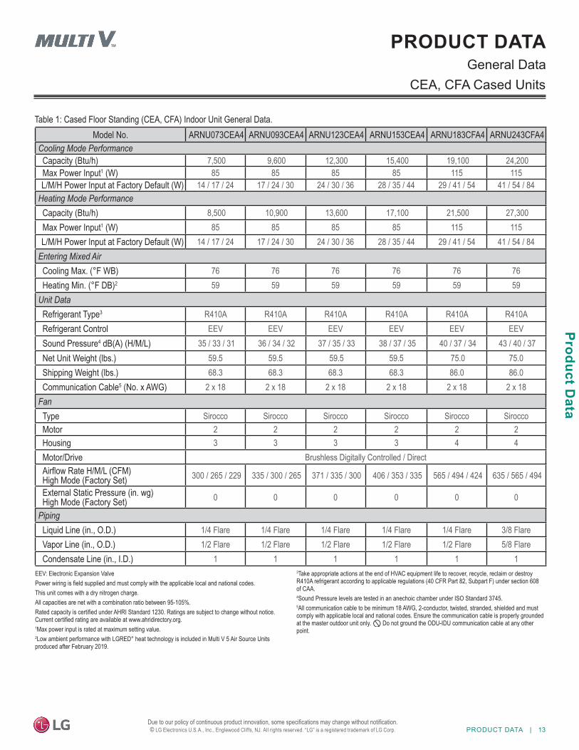
PRODUCT DATAGeneral Data
Model No. ARNU073CEA4 ARNU093CEA4 ARNU123CEA4 ARNU153CEA4 ARNU183CFA4 ARNU243CFA4Cooling Mode PerformanceCapacity (Btu/h) 7,500 9,600 12,300 15,400 19,100 24,200 Max Power Input1 (W) 85 85 85 85 115 115L/M/H Power Input at Factory Default (W) 14 / 17 / 24 17 / 24 / 30 24 / 30 / 36 28 / 35 / 44 29 / 41 / 54 41 / 54 / 84
Heating Mode PerformanceCapacity (Btu/h) 8,500 10,900 13,600 17,100 21,500 27,300 Max Power Input1 (W) 85 85 85 85 115 115L/M/H Power Input at Factory Default (W) 14 / 17 / 24 17 / 24 / 30 24 / 30 / 36 28 / 35 / 44 29 / 41 / 54 41 / 54 / 84
Entering Mixed AirCooling Max. (°F WB) 76 76 76 76 76 76Heating Min. (°F DB)2 59 59 59 59 59 59
Unit DataRefrigerant Type3 R410A R410A R410A R410A R410A R410ARefrigerant Control EEV EEV EEV EEV EEV EEVSound Pressure4 dB(A) (H/M/L) 35 / 33 / 31 36 / 34 / 32 37 / 35 / 33 38 / 37 / 35 40 / 37 / 34 43 / 40 / 37 Net Unit Weight (lbs.) 59.5 59.5 59.5 59.5 75.0 75.0Shipping Weight (lbs.) 68.3 68.3 68.3 68.3 86.0 86.0Communication Cable5 (No. x AWG) 2 x 18 2 x 18 2 x 18 2 x 18 2 x 18 2 x 18
FanType Sirocco Sirocco Sirocco Sirocco Sirocco SiroccoMotor 2 2 2 2 2 2Housing 3 3 3 3 4 4Motor/Drive Brushless Digitally Controlled / DirectAirflow Rate H/M/L (CFM)High Mode (Factory Set) 300 / 265 / 229 335 / 300 / 265 371 / 335 / 300 406 / 353 / 335 565 / 494 / 424 635 / 565 / 494
External Static Pressure (in. wg)High Mode (Factory Set) 0 0 0 0 0 0
PipingLiquid Line (in., O.D.) 1/4 Flare 1/4 Flare 1/4 Flare 1/4 Flare 1/4 Flare 3/8 FlareVapor Line (in., O.D.) 1/2 Flare 1/2 Flare 1/2 Flare 1/2 Flare 1/2 Flare 5/8 FlareCondensate Line (in., I.D.) 1 1 1 1 1 1
Table 1: Cased Floor Standing (CEA, CFA) Indoor Unit General Data.
EEV: Electronic Expansion ValvePower wiring is field supplied and must comply with the applicable local and national codes.This unit comes with a dry nitrogen charge.All capacities are net with a combination ratio between 95-105%.Rated capacity is certified under AHRI Standard 1230. Ratings are subject to change without notice. Current certified rating are available at www.ahridirectory.org.1Max power input is rated at maximum setting value.2Low ambient performance with LGRED° heat technology is included in Multi V 5 Air Source Units produced after February 2019.
3Take appropriate actions at the end of HVAC equipment life to recover, recycle, reclaim or destroy R410A refrigerant according to applicable regulations (40 CFR Part 82, Subpart F) under section 608 of CAA. 4Sound Pressure levels are tested in an anechoic chamber under ISO Standard 3745.5All communication cable to be minimum 18 AWG, 2-conductor, twisted, stranded, shielded and must comply with applicable local and national codes. Ensure the communication cable is properly grounded at the master outdoor unit only. Do not ground the ODU-IDU communication cable at any other point.
CEA, CFA Cased Units
14 | PRODUCT DATA
MUL
TI V
Flo
or S
tand
ing
Indo
or U
nit E
ngin
eerin
g M
anua
l
Due to our policy of continuous product innovation, some specifications may change without notification. © LG Electronics U.S.A., Inc., Englewood Cliffs, NJ. All rights reserved. “LG” is a registered trademark of LG Corp.
Model No. ARNU073CEU4 ARNU093CEU4 ARNU123CEU4 ARNU153CEU4 ARNU183CFU4 ARNU243CFU4Cooling Mode PerformanceCapacity (Btu/h) 7,500 9,600 12,300 15,400 19,100 24,200 Max Power Input1 (W) 85 85 85 85 115 115L/M/H Power Input at Factory Default (W) 14 / 17 / 24 17 / 24 / 30 24 / 30 / 36 28 / 35 / 44 29 / 41 / 54 41 / 54 / 84
Heating Mode PerformanceCapacity (Btu/h) 8,500 10,900 13,600 17,100 21,500 27,300 Max Power Input1 (W) 85 85 85 85 115 115L/M/H Power Input at Factory Default (W) 14 / 17 / 24 17 / 24 / 30 24 / 30 / 36 28 / 35 / 44 29 / 41 / 54 41 / 54 / 84
Entering Mixed AirCooling Max. (°F WB) 76 76 76 76 76 76Heating Min. (°F DB)2 59 59 59 59 59 59
Unit DataRefrigerant Type3 R410A R410A R410A R410A R410A R410ARefrigerant Control EEV EEV EEV EEV EEV EEVSound Pressure4 dB(A) (H/M/L) 35 / 33 / 31 36 / 34 / 32 37 / 35 / 33 38 / 37 / 35 40 / 37 / 34 43 / 40 / 37 Net Unit Weight (lbs.) 46.3 46.3 46.3 46.3 58.4 58.4Shipping Weight (lbs.) 56.2 56.2 56.2 56.2 68.3 68.3Communication Cable5 (No. x AWG) 2 x 18 2 x 18 2 x 18 2 x 18 2 x 18 2 x 18
FanType Sirocco Sirocco Sirocco Sirocco Sirocco SiroccoMotor 2 2 2 2 2 2Housing 3 3 3 3 4 4Motor/Drive Brushless Digitally Controlled / DirectAirflow Rate H/M/L (CFM)High Mode (Factory Set) 300 / 265 / 229 335 / 300 / 265 371 / 335 / 300 406 / 353 / 335 565 / 494 / 424 635 / 565 / 494
External Static Pressure (in. wg)High Mode (Factory Set) 0 0 0 0 0 0
PipingLiquid Line (in., O.D.) 1/4 Flare 1/4 Flare 1/4 Flare 1/4 Flare 1/4 Flare 3/8 FlareVapor Line (in., O.D.) 1/2 Flare 1/2 Flare 1/2 Flare 1/2 Flare 1/2 Flare 5/8 FlareCondensate Line (in., I.D.) 1 1 1 1 1 1
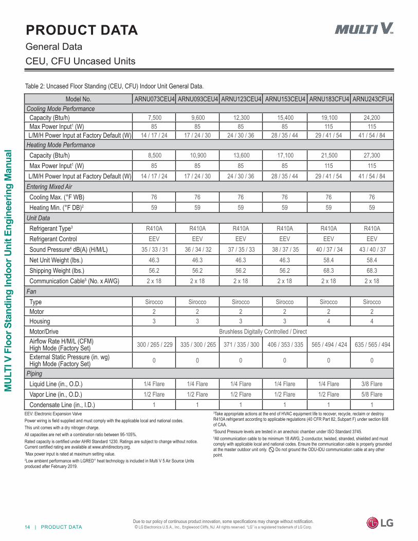
Table 2: Uncased Floor Standing (CEU, CFU) Indoor Unit General Data.
PRODUCT DATAGeneral DataCEU, CFU Uncased Units
EEV: Electronic Expansion ValvePower wiring is field supplied and must comply with the applicable local and national codes.This unit comes with a dry nitrogen charge.All capacities are net with a combination ratio between 95-105%.Rated capacity is certified under AHRI Standard 1230. Ratings are subject to change without notice. Current certified rating are available at www.ahridirectory.org.1Max power input is rated at maximum setting value.2Low ambient performance with LGRED° heat technology is included in Multi V 5 Air Source Units produced after February 2019.
3Take appropriate actions at the end of HVAC equipment life to recover, recycle, reclaim or destroy R410A refrigerant according to applicable regulations (40 CFR Part 82, Subpart F) under section 608 of CAA. 4Sound Pressure levels are tested in an anechoic chamber under ISO Standard 3745.5All communication cable to be minimum 18 AWG, 2-conductor, twisted, stranded, shielded and must comply with applicable local and national codes. Ensure the communication cable is properly grounded at the master outdoor unit only. Do not ground the ODU-IDU communication cable at any other point.
PRODUCT DATA | 15
Product Data
Due to our policy of continuous product innovation, some specifications may change without notification. © LG Electronics U.S.A., Inc., Englewood Cliffs, NJ. All rights reserved. “LG” is a registered trademark of LG Corp.
PRODUCT DATAElectrical Data
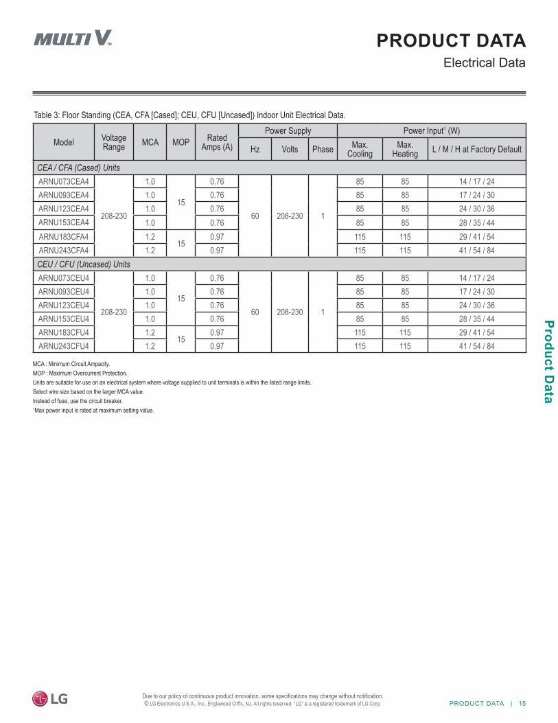
Table 3: Floor Standing (CEA, CFA [Cased]; CEU, CFU [Uncased]) Indoor Unit Electrical Data.
Model Voltage Range MCA MOP Rated
Amps (A)
Power Supply Power Input1 (W)
Hz Volts Phase Max. Cooling
Max. Heating L / M / H at Factory Default
CEA / CFA (Cased) UnitsARNU073CEA4
208-230
1.0
15
0.76
60 208-230 1
85 85 14 / 17 / 24ARNU093CEA4 1.0 0.76 85 85 17 / 24 / 30ARNU123CEA4 1.0 0.76 85 85 24 / 30 / 36ARNU153CEA4 1.0 0.76 85 85 28 / 35 / 44ARNU183CFA4 1.2
150.97 115 115 29 / 41 / 54
ARNU243CFA4 1.2 0.97 115 115 41 / 54 / 84CEU / CFU (Uncased) UnitsARNU073CEU4
208-230
1.0
15
0.76
60 208-230 1
85 85 14 / 17 / 24ARNU093CEU4 1.0 0.76 85 85 17 / 24 / 30ARNU123CEU4 1.0 0.76 85 85 24 / 30 / 36ARNU153CEU4 1.0 0.76 85 85 28 / 35 / 44ARNU183CFU4 1.2
150.97 115 115 29 / 41 / 54
ARNU243CFU4 1.2 0.97 115 115 41 / 54 / 84
MCA : Minimum Circuit Ampacity.MOP : Maximum Overcurrent Protection.Units are suitable for use on an electrical system where voltage supplied to unit terminals is within the listed range limits.Select wire size based on the larger MCA value.Instead of fuse, use the circuit breaker.1Max power input is rated at maximum setting value.
16 | PRODUCT DATA
MUL
TI V
Flo
or S
tand
ing
Indo
or U
nit E
ngin
eerin
g M
anua
l
Due to our policy of continuous product innovation, some specifications may change without notification. © LG Electronics U.S.A., Inc., Englewood Cliffs, NJ. All rights reserved. “LG” is a registered trademark of LG Corp.
PRODUCT DATAExternal Dimensions
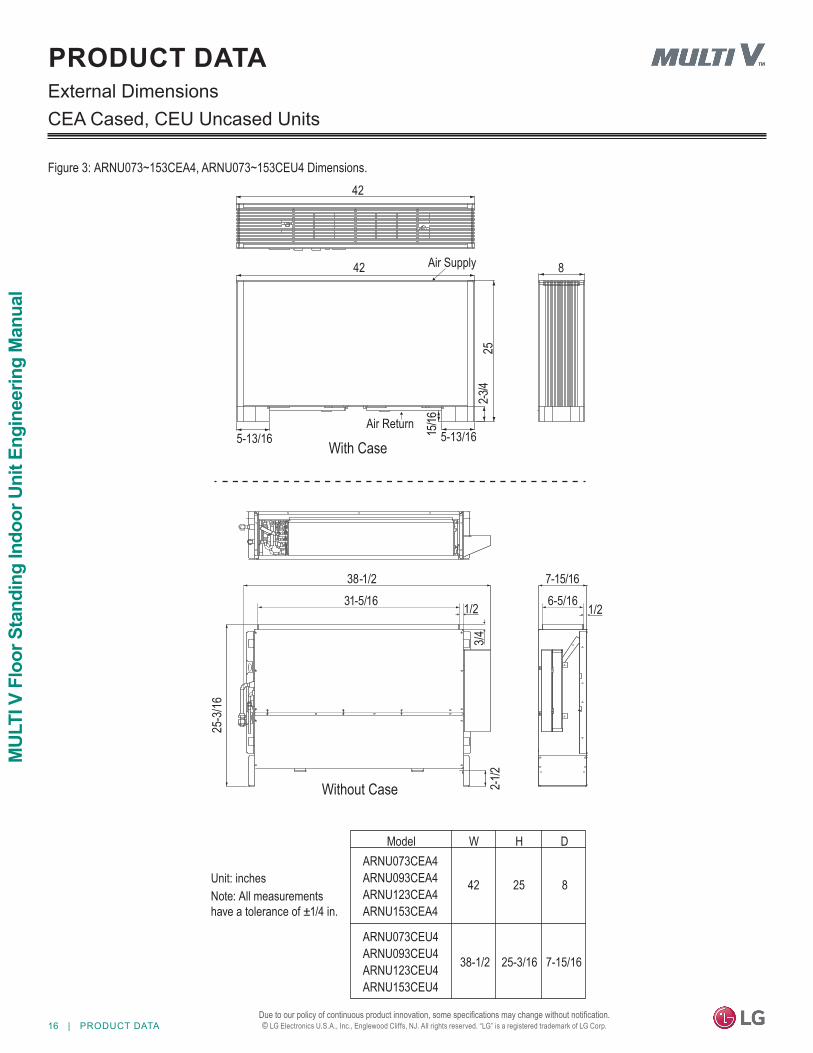
Figure 3: ARNU073~153CEA4, ARNU073~153CEU4 Dimensions.
CEA Cased, CEU Uncased Units
With Case
42
42
5-13/16 5-13/1615/16
2-3/4
25
8Air Supply
Air Return
Unit: inchesNote: All measurements have a tolerance of ±1/4 in.
Without Case
38-1/231-5/16
25-3
/16
1/2
3/42-1
/2
7-15/166-5/16 1/2
WModelARNU073CEA4ARNU093CEA4ARNU123CEA4ARNU153CEA4
H
42 25 8
ARNU073CEU4ARNU093CEU4ARNU123CEU4ARNU153CEU4
38-1/2 25-3/16 7-15/16
D
PRODUCT DATA | 17
Product Data
Due to our policy of continuous product innovation, some specifications may change without notification. © LG Electronics U.S.A., Inc., Englewood Cliffs, NJ. All rights reserved. “LG” is a registered trademark of LG Corp.
PRODUCT DATAExternal Dimensions
CFA Cased, CFU Uncased Units
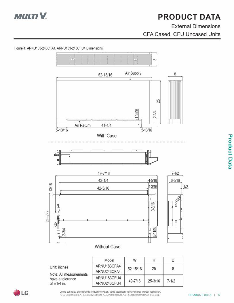
Figure 4: ARNU183-243CFA4, ARNU183-243CFU4 Dimensions.
8
52-15/16
252-
3/4
5-13/1641-1/4
1-15/1
65-13/16
7-1/26-5/16
49-7/1643-1/4
42-3/16
4-5/161-3/16
3-3/16
5-11/1
6
2-3/4
13/16
25-5
/32
8
With Case
Unit: inchesNote: All measurements have a toleranceof ±1/4 in.
Without Case
Air Supply
Air Return
1/2
WModelARNU183CFA4ARNU243CFA4
H
52-15/16 25 8
ARNU183CFU4ARNU243CFU4 49-7/16 25-3/16 7-1/2
D
18 | PRODUCT DATA
MUL
TI V
Flo
or S
tand
ing
Indo
or U
nit E
ngin
eerin
g M
anua
l
Due to our policy of continuous product innovation, some specifications may change without notification. © LG Electronics U.S.A., Inc., Englewood Cliffs, NJ. All rights reserved. “LG” is a registered trademark of LG Corp.
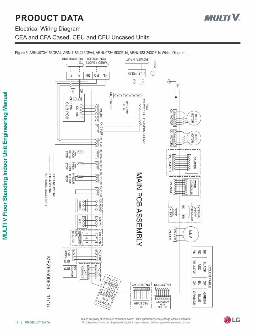
PRODUCT DATAElectrical Wiring DiagramCEA and CFA Cased, CEU and CFU Uncased Units
Figure 5: ARNU073~153CEA4, ARNU183-243CFA4, ARNU073~153CEU4, ARNU183-243CFU4 Wiring Diagram.
MEZ66590606 11/15
PRODUCT DATA | 19
Product Data
Due to our policy of continuous product innovation, some specifications may change without notification. © LG Electronics U.S.A., Inc., Englewood Cliffs, NJ. All rights reserved. “LG” is a registered trademark of LG Corp.
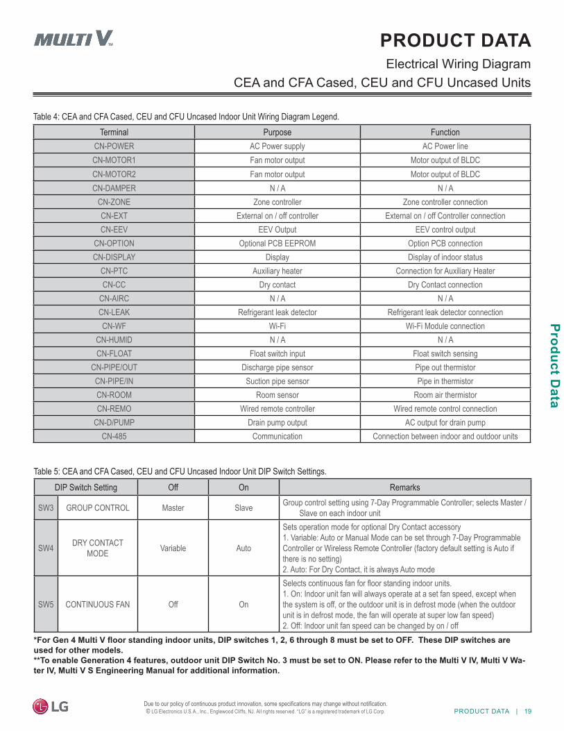
Table 4: CEA and CFA Cased, CEU and CFU Uncased Indoor Unit Wiring Diagram Legend.
Table 5: CEA and CFA Cased, CEU and CFU Uncased Indoor Unit DIP Switch Settings.
PRODUCT DATAElectrical Wiring Diagram
CEA and CFA Cased, CEU and CFU Uncased Units
*For Gen 4 Multi V floor standing indoor units, DIP switches 1, 2, 6 through 8 must be set to OFF. These DIP switches are used for other models. **To enable Generation 4 features, outdoor unit DIP Switch No. 3 must be set to ON. Please refer to the Multi V IV, Multi V Wa-ter IV, Multi V S Engineering Manual for additional information.
DIP Switch Setting Off On Remarks
SW3 GROUP CONTROL Master Slave Group control setting using 7-Day Programmable Controller; selects Master / Slave on each indoor unit
SW4 DRY CONTACT MODE Variable Auto
Sets operation mode for optional Dry Contact accessory1. Variable: Auto or Manual Mode can be set through 7-Day ProgrammableController or Wireless Remote Controller (factory default setting is Auto if there is no setting)2. Auto: For Dry Contact, it is always Auto mode
SW5 CONTINUOUS FAN Off On
Selects continuous fan for floor standing indoor units.1. On: Indoor unit fan will always operate at a set fan speed, except when the system is off, or the outdoor unit is in defrost mode (when the outdoor unit is in defrost mode, the fan will operate at super low fan speed)2. Off: Indoor unit fan speed can be changed by on / off
Terminal Purpose FunctionCN-POWER AC Power supply AC Power lineCN-MOTOR1 Fan motor output Motor output of BLDCCN-MOTOR2 Fan motor output Motor output of BLDCCN-DAMPER N / A N / A
CN-ZONE Zone controller Zone controller connectionCN-EXT External on / off controller External on / off Controller connectionCN-EEV EEV Output EEV control output
CN-OPTION Optional PCB EEPROM Option PCB connectionCN-DISPLAY Display Display of indoor status
CN-PTC Auxiliary heater Connection for Auxiliary HeaterCN-CC Dry contact Dry Contact connection
CN-AIRC N / A N / ACN-LEAK Refrigerant leak detector Refrigerant leak detector connectionCN-WF Wi-Fi Wi-Fi Module connection
CN-HUMID N / A N / ACN-FLOAT Float switch input Float switch sensing
CN-PIPE/OUT Discharge pipe sensor Pipe out thermistorCN-PIPE/IN Suction pipe sensor Pipe in thermistorCN-ROOM Room sensor Room air thermistorCN-REMO Wired remote controller Wired remote control connection
CN-D/PUMP Drain pump output AC output for drain pumpCN-485 Communication Connection between indoor and outdoor units
20 | PRODUCT DATA
MUL
TI V
Flo
or S
tand
ing
Indo
or U
nit E
ngin
eerin
g M
anua
l
Due to our policy of continuous product innovation, some specifications may change without notification. © LG Electronics U.S.A., Inc., Englewood Cliffs, NJ. All rights reserved. “LG” is a registered trademark of LG Corp.
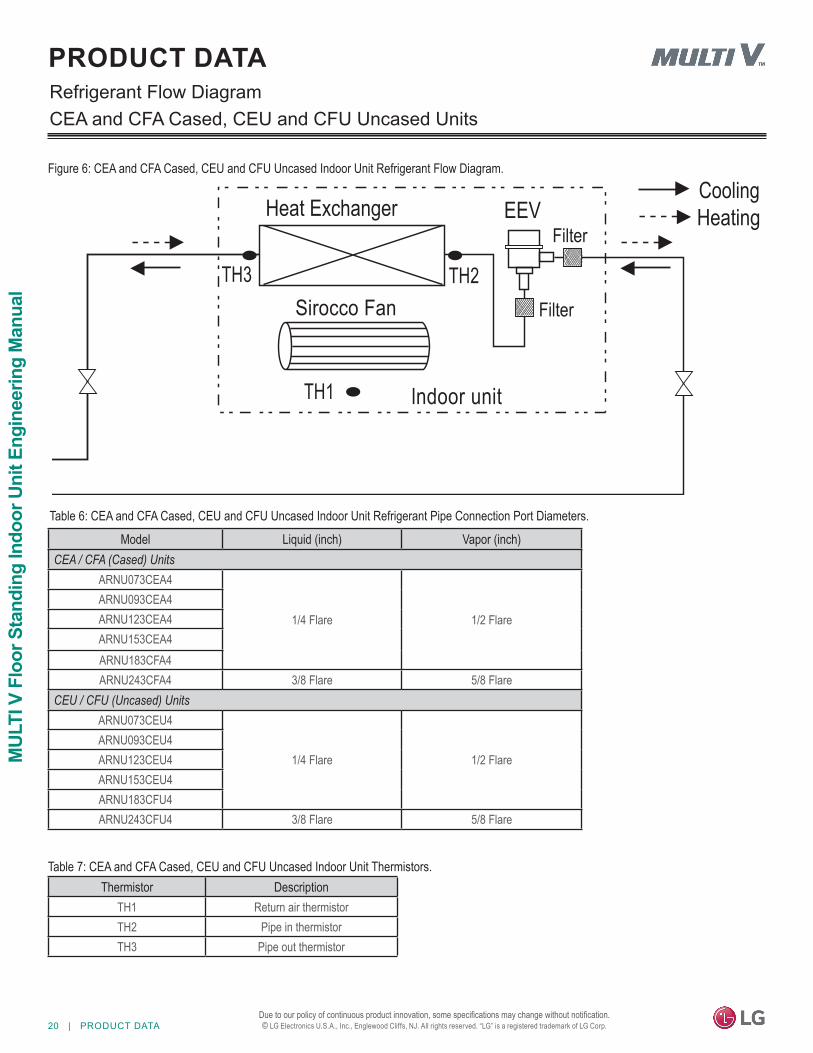
PRODUCT DATARefrigerant Flow Diagram
Figure 6: CEA and CFA Cased, CEU and CFU Uncased Indoor Unit Refrigerant Flow Diagram.
Table 6: CEA and CFA Cased, CEU and CFU Uncased Indoor Unit Refrigerant Pipe Connection Port Diameters.
Thermistor DescriptionTH1 Return air thermistorTH2 Pipe in thermistorTH3 Pipe out thermistor
Table 7: CEA and CFA Cased, CEU and CFU Uncased Indoor Unit Thermistors.
CEA and CFA Cased, CEU and CFU Uncased Units
Heat Exchanger
Sirocco FanTH3
TH1
TH2
lndoor unit
EEV HeatingCooling
Filter
Filter
Model Liquid (inch) Vapor (inch)CEA / CFA (Cased) Units
ARNU073CEA4
1/4 Flare 1/2 FlareARNU093CEA4ARNU123CEA4ARNU153CEA4ARNU183CFA4ARNU243CFA4 3/8 Flare 5/8 Flare
CEU / CFU (Uncased) UnitsARNU073CEU4
1/4 Flare 1/2 FlareARNU093CEU4ARNU123CEU4ARNU153CEU4ARNU183CFU4ARNU243CFU4 3/8 Flare 5/8 Flare
PRODUCT DATA | 21
Product Data
Due to our policy of continuous product innovation, some specifications may change without notification. © LG Electronics U.S.A., Inc., Englewood Cliffs, NJ. All rights reserved. “LG” is a registered trademark of LG Corp.
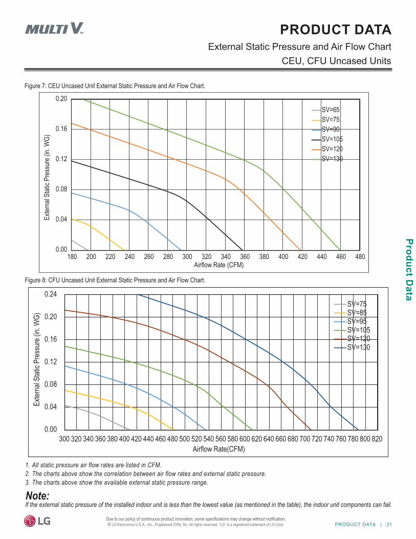
PRODUCT DATAExternal Static Pressure and Air Flow Chart
CEU, CFU Uncased Units
Figure 7: CEU Uncased Unit External Static Pressure and Air Flow Chart.
Figure 8: CFU Uncased Unit External Static Pressure and Air Flow Chart.
1� All static pressure air flow rates are listed in CFM.2� The charts above show the correlation between air flow rates and external static pressure.3� The charts above show the available external static pressure range.
If the external static pressure of the installed indoor unit is less than the lowest value (as mentioned in the table), the indoor unit components can fail.
0.00
0.04
0.08
0.12
0.16
0.20
180 200 220 240 260 280 300 320 340 360 380 400 420 440 460 480
Exter
nal S
tatic
Pres
sure
(in. W
G)
Airflow Rate (CFM)
SV=65SV=75SV=90SV=105SV=120SV=130
0.00
0.04
0.08
0.12
0.16
0.20
0.24
300 320 340 360 380 400 420 440 460 480 500 520 540 560 580 600 620 640 660 680 700 720 740 760 780 800 820
Exter
nal S
tatic
Pres
sure
(in. W
G)
Airflow Rate(CFM)
SV=75SV=85SV=95SV=105SV=120SV=130
22 | PRODUCT DATA
MUL
TI V
Flo
or S
tand
ing
Indo
or U
nit E
ngin
eerin
g M
anua
l
Due to our policy of continuous product innovation, some specifications may change without notification. © LG Electronics U.S.A., Inc., Englewood Cliffs, NJ. All rights reserved. “LG” is a registered trademark of LG Corp.
PRODUCT DATAAcoustic DataSound Pressure Levels
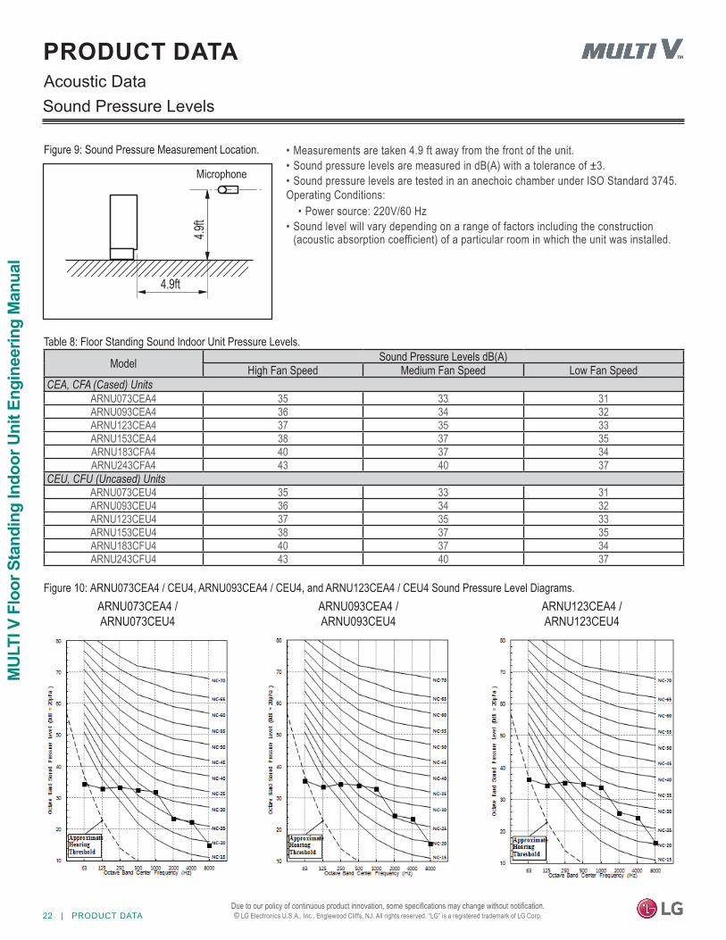
Figure 9: Sound Pressure Measurement Location.
Model Sound Pressure Levels dB(A)High Fan Speed Medium Fan Speed Low Fan Speed
CEA, CFA (Cased) UnitsARNU073CEA4 35 33 31ARNU093CEA4 36 34 32ARNU123CEA4 37 35 33ARNU153CEA4 38 37 35ARNU183CFA4 40 37 34ARNU243CFA4 43 40 37
CEU, CFU (Uncased) UnitsARNU073CEU4 35 33 31ARNU093CEU4 36 34 32ARNU123CEU4 37 35 33ARNU153CEU4 38 37 35ARNU183CFU4 40 37 34ARNU243CFU4 43 40 37
Table 8: Floor Standing Sound Indoor Unit Pressure Levels.
Figure 10: ARNU073CEA4 / CEU4, ARNU093CEA4 / CEU4, and ARNU123CEA4 / CEU4 Sound Pressure Level Diagrams.
• Measurements are taken 4.9 ft away from the front of the unit.• Sound pressure levels are measured in dB(A) with a tolerance of ±3.• Sound pressure levels are tested in an anechoic chamber under ISO Standard 3745.Operating Conditions:
• Power source: 220V/60 Hz• Sound level will vary depending on a range of factors including the construction
(acoustic absorption coefficient) of a particular room in which the unit was installed.
4.9ft
4.9ft
Microphone
ARNU073CEA4 / ARNU073CEU4
ARNU093CEA4 / ARNU093CEU4
ARNU123CEA4 / ARNU123CEU4
PRODUCT DATA | 23
Product Data
Due to our policy of continuous product innovation, some specifications may change without notification. © LG Electronics U.S.A., Inc., Englewood Cliffs, NJ. All rights reserved. “LG” is a registered trademark of LG Corp.
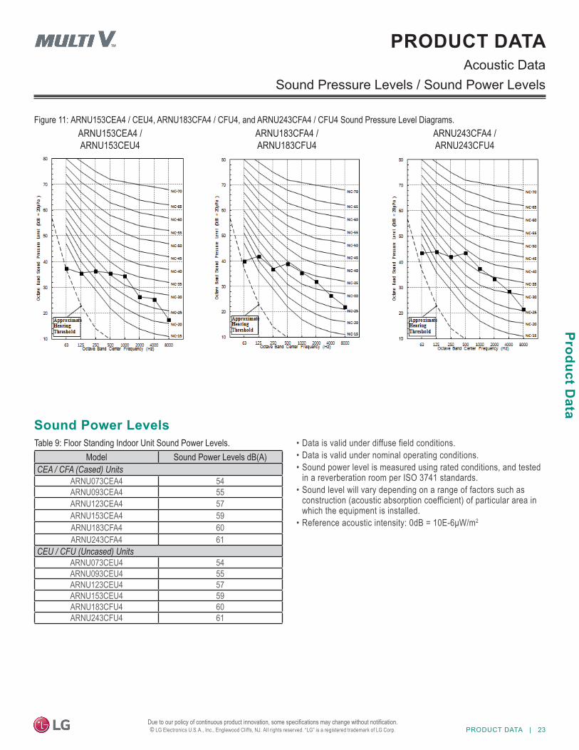
Figure 11: ARNU153CEA4 / CEU4, ARNU183CFA4 / CFU4, and ARNU243CFA4 / CFU4 Sound Pressure Level Diagrams.
PRODUCT DATAAcoustic Data
Sound Pressure Levels / Sound Power Levels
• Data is valid under diffuse field conditions.• Data is valid under nominal operating conditions.• Sound power level is measured using rated conditions, and tested
in a reverberation room per ISO 3741 standards.• Sound level will vary depending on a range of factors such as
construction (acoustic absorption coefficient) of particular area in which the equipment is installed.
• Reference acoustic intensity: 0dB = 10E-6μW/m2
Model Sound Power Levels dB(A)CEA / CFA (Cased) Units
ARNU073CEA4 54ARNU093CEA4 55ARNU123CEA4 57ARNU153CEA4 59ARNU183CFA4 60ARNU243CFA4 61
CEU / CFU (Uncased) UnitsARNU073CEU4 54ARNU093CEU4 55ARNU123CEU4 57ARNU153CEU4 59ARNU183CFU4 60ARNU243CFU4 61
Table 9: Floor Standing Indoor Unit Sound Power Levels.
Sound Power Levels
ARNU153CEA4 / ARNU153CEU4
ARNU183CFA4 / ARNU183CFU4
ARNU243CFA4 / ARNU243CFU4
24 | PRODUCT DATA
MUL
TI V
Flo
or S
tand
ing
Indo
or U
nit E
ngin
eerin
g M
anua
l
Due to our policy of continuous product innovation, some specifications may change without notification. © LG Electronics U.S.A., Inc., Englewood Cliffs, NJ. All rights reserved. “LG” is a registered trademark of LG Corp.
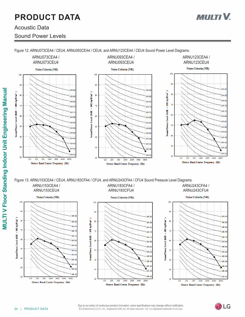
Figure 12: ARNU073CEA4 / CEU4, ARNU093CEA4 / CEU4, and ARNU123CEA4 / CEU4 Sound Power Level Diagrams.
PRODUCT DATAAcoustic DataSound Power Levels
Figure 13: ARNU153CEA4 / CEU4, ARNU183CFA4 / CFU4, and ARNU243CFA4 / CFU4 Sound Pressure Level Diagrams.
ARNU073CEA4 / ARNU073CEU4
ARNU093CEA4 / ARNU093CEU4
ARNU123CEA4 / ARNU123CEU4
ARNU153CEA4 / ARNU153CEU4
ARNU183CFA4 / ARNU183CFU4
ARNU243CFA4 / ARNU243CFU4
PRODUCT DATA | 25
Product Data
Due to our policy of continuous product innovation, some specifications may change without notification. © LG Electronics U.S.A., Inc., Englewood Cliffs, NJ. All rights reserved. “LG” is a registered trademark of LG Corp.
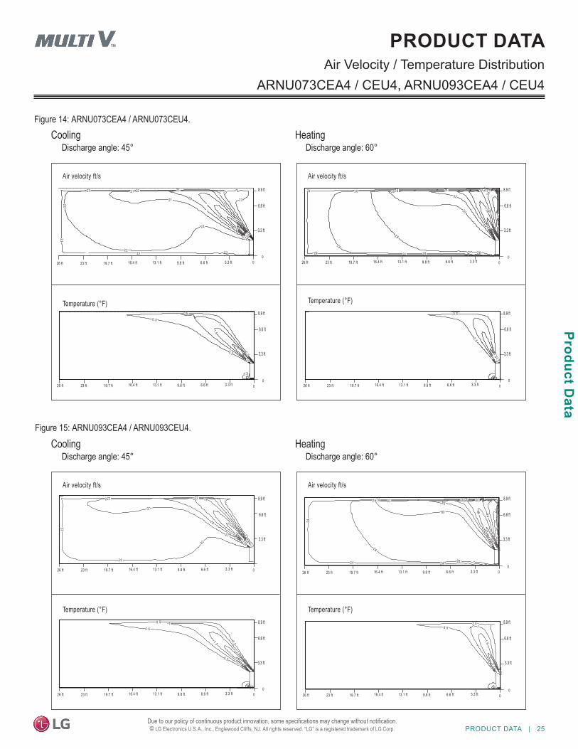
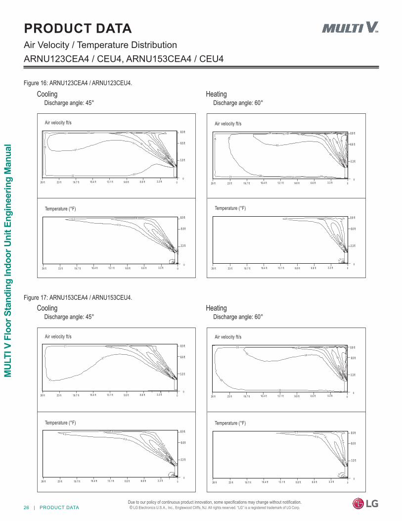
PRODUCT DATAAir Velocity / Temperature Distribution
ARNU073CEA4 / CEU4, ARNU093CEA4 / CEU4
Figure 14: ARNU073CEA4 / ARNU073CEU4.
0 .5
0.50 .5
0 .5
0 .5
1
1
1.52
2
31516
18
18
19
19
20
20
2121
21
21
22
22
22
22
22
23
2323
23
23 23
00
00
8.9 ft
6.6 ft
3.3 ft
8.9 ft
6.6 ft
3.3 ft
Air velocity ft/s
Temperature (°F)
CoolingDischarge angle: 45°
HeatingDischarge angle: 60°
242424
24 24 24
26
2626
26
26
2828
28
28
3030
30
3232 34
3436
3638
0 .5
0 .5
0.5
11
1
1.5
1.5
2
4
00
00
8.9 ft
6.6 ft
3.3 ft
8.9 ft
6.6 ft
3.3 ft
Air velocity ft/s
Temperature (°F)
0.5
0 .5
0 .5
0 .5
1
1
1
1.5
2
3.5
16
17 18
18
19
19 20
20
20
21
2121
21
21 22
2222
22
22
22
00
0
8.9 ft
6.6 ft
3.3 ft
8.9 ft
6.6 ft
3.3 ft
Air velocity ft/s
Temperature (°F)
CoolingDischarge angle: 45°
HeatingDischarge angle: 60°
24
2424
24
24 24
262626
26
26
83
8383
83
828280
8084
84
86
0302
3.5
3 .53 .5 1
1.5
1.5
2
2.5
00
00
8.9 ft
6.6 ft
3.3 ft
8.9 ft
6.6 ft
3.3 ft
Air velocity ft/s
Temperature (°F)
6.6 ft26 ft 23 ft 19.7 ft 16.4 ft 13.1 ft 9.8 ft 3.3 ft
6.6 ft26 ft 23 ft 19.7 ft 16.4 ft 13.1 ft 9.8 ft 3.3 ft
6.6 ft26 ft 23 ft 19.7 ft 16.4 ft 13.1 ft 9.8 ft 3.3 ft
6.6 ft26 ft 23 ft 19.7 ft 16.4 ft 13.1 ft 9.8 ft 3.3 ft 6.6 ft26 ft 23 ft 19.7 ft 16.4 ft 13.1 ft 9.8 ft 3.3 ft
6.6 ft26 ft 23 ft 19.7 ft 16.4 ft 13.1 ft 9.8 ft 3.3 ft
6.6 ft26 ft 23 ft 19.7 ft 16.4 ft 13.1 ft 9.8 ft 3.3 ft
6.6 ft26 ft 23 ft 19.7 ft 16.4 ft 13.1 ft 9.8 ft 3.3 ft
Figure 15: ARNU093CEA4 / ARNU093CEU4.
26 | PRODUCT DATA
MUL
TI V
Flo
or S
tand
ing
Indo
or U
nit E
ngin
eerin
g M
anua
l
Due to our policy of continuous product innovation, some specifications may change without notification. © LG Electronics U.S.A., Inc., Englewood Cliffs, NJ. All rights reserved. “LG” is a registered trademark of LG Corp.
PRODUCT DATAAir Velocity / Temperature DistributionARNU123CEA4 / CEU4, ARNU153CEA4 / CEU4
Figure 16: ARNU123CEA4 / ARNU123CEU4.
0 .5
0.50 .5
0 .5
0 .5
1
1
1
1.5
1 .52
2.5
15
16
17
18
19
19 20
20
20
21
2121
21
21
22
2222
22
22 22
00
00
8.9 ft
6.6 ft
3.3 ft
8.9 ft
6.6 ft
3.3 ft
Air velocity ft/s
Temperature (°F)
6.6 ft26 ft 23 ft 19.7 ft 16.4 ft 13.1 ft 9.8 ft 3.3 ft
CoolingDischarge angle: 45°
HeatingDischarge angle: 60°
2424
24
24 24
2626
26
26 26
8383
83
83
82
82
8280
80
84
84 8603
02
3.53.5
3.5
3. 5
1
1
1.51 .5
1.5
2.5
00
00
8.9 ft
6.6 ft
3.3 ft
8.9 ft
6.6 ft
3.3 ft
Air velocity ft/s
Temperature (°F)
1516
17
18
18
19
19 20
20
20
21
2121
21
21
21
0.5
0 .50 .5
0 .5
1
1
1
1
1.5
1 .5
1.5
2
2
2
2.5
3
3 .54
00
00
8.9 ft
6.6 ft
3.3 ft
8.9 ft
6.6 ft
3.3 ft
Air velocity ft/s
Temperature (°F)
CoolingDischarge angle: 45°
HeatingDischarge angle: 60°
2828
28
28 28
3030
30
30
3232
3234
34
34
36
3840
0.5
0 .50 .5
0.5
1.0
1 .0
1.02 .0
00
00
8.9 ft
6.6 ft
3.3 ft
8.9 ft
6.6 ft
3.3 ft
Air velocity ft/s
Temperature (°F)
6.6 ft26 ft 23 ft 19.7 ft 16.4 ft 13.1 ft 9.8 ft 3.3 ft 6.6 ft26 ft 23 ft 19.7 ft 16.4 ft 13.1 ft 9.8 ft 3.3 ft
6.6 ft26 ft 23 ft 19.7 ft 16.4 ft 13.1 ft 9.8 ft 3.3 ft
6.6 ft26 ft 23 ft 19.7 ft 16.4 ft 13.1 ft 9.8 ft 3.3 ft
6.6 ft26 ft 23 ft 19.7 ft 16.4 ft 13.1 ft 9.8 ft 3.3 ft 6.6 ft26 ft 23 ft 19.7 ft 16.4 ft 13.1 ft 9.8 ft 3.3 ft
6.6 ft26 ft 23 ft 19.7 ft 16.4 ft 13.1 ft 9.8 ft 3.3 ft
Figure 17: ARNU153CEA4 / ARNU153CEU4.
PRODUCT DATA | 27
Product Data
Due to our policy of continuous product innovation, some specifications may change without notification. © LG Electronics U.S.A., Inc., Englewood Cliffs, NJ. All rights reserved. “LG” is a registered trademark of LG Corp.
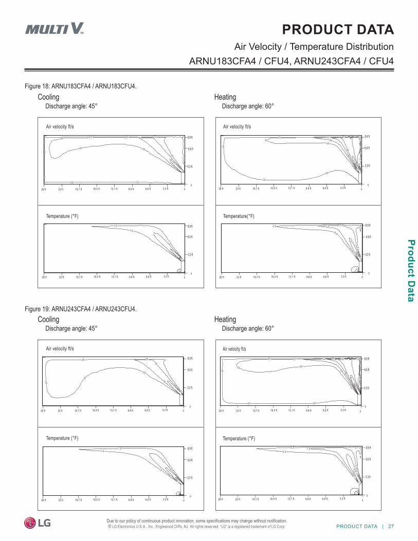
PRODUCT DATAAir Velocity / Temperature Distribution
ARNU183CFA4 / CFU4, ARNU243CFA4 / CFU4
Figure 18: ARNU183CFA4 / ARNU183CFU4.
Figure 19: ARNU243CFA4 / ARNU243CFU4.
16
18
18
20
2020
20 20
22
2222
22
2 2 22
1.0
1 .01 .0
2.0
2 .
3 .0
00
6.6 ft 00
8.9 ft
6.6 ft
3.3 ft
8.9 ft
6.6 ft
3.3 ft
Air velocity ft/s
Temperature (°F)
26 ft 23 ft 19.7 ft 16.4 ft 13.1 ft 9.8 ft 3.3 ft
CoolingDischarge angle: 45°
HeatingDischarge angle: 60°
30
3030
30
30
30
32
3232
32
3434
36
36
38
38
4042
0.5
0.50 .5
0 .5
1.0
1 .0
1.02. 0
00
00
8.9 ft
6.6 ft
3.3 ft
8.9 ft
6.6 ft
3.3 ft
Air velocity ft/s
Temperature(°F)
18
18
20
2020
20
20
20
1.0
1 .01 .0
1.0
2 .0
2 .0
3 .0
00
00
8.9 ft
6.6 ft
3.3 ft
8.9 ft
6.6 ft
3.3 ft
Air velocity ft/s
Temperature (°F)
CoolingDischarge angle: 45°
HeatingDischarge angle: 60°
0.
0 .50 .50 .5
0.5
1.0
1 .0
1.02. 0
2 .0
2 .0
3.0
4 0
30
3030
30
30 30
3232
32 32
32
34
3 4
34
36
36
38
40
00
00
8.9 ft
6.6 ft
3.3 ft
8.9 ft
6.6 ft
3.3 ft
Air velocity ft/s
Temperature (°F)
6.6 ft26 ft 23 ft 19.7 ft 16.4 ft 13.1 ft 9.8 ft 3.3 ft
6.6 ft26 ft 23 ft 19.7 ft 16.4 ft 13.1 ft 9.8 ft 3.3 ft
6.6 ft26 ft 23 ft 19.7 ft 16.4 ft 13.1 ft 9.8 ft 3.3 ft
6.6 ft26 ft 23 ft 19.7 ft 16.4 ft 13.1 ft 9.8 ft 3.3 ft
6.6 ft26 ft 23 ft 19.7 ft 16.4 ft 13.1 ft 9.8 ft 3.3 ft
6.6 ft26 ft 23 ft 19.7 ft 16.4 ft 13.1 ft 9.8 ft 3.3 ft 6.6 ft26 ft 23 ft 19.7 ft 16.4 ft 13.1 ft 9.8 ft 3.3 ft
28 | PRODUCT DATA
MUL
TI V
Flo
or S
tand
ing
Indo
or U
nit E
ngin
eerin
g M
anua
l
Due to our policy of continuous product innovation, some specifications may change without notification. © LG Electronics U.S.A., Inc., Englewood Cliffs, NJ. All rights reserved. “LG” is a registered trademark of LG Corp.
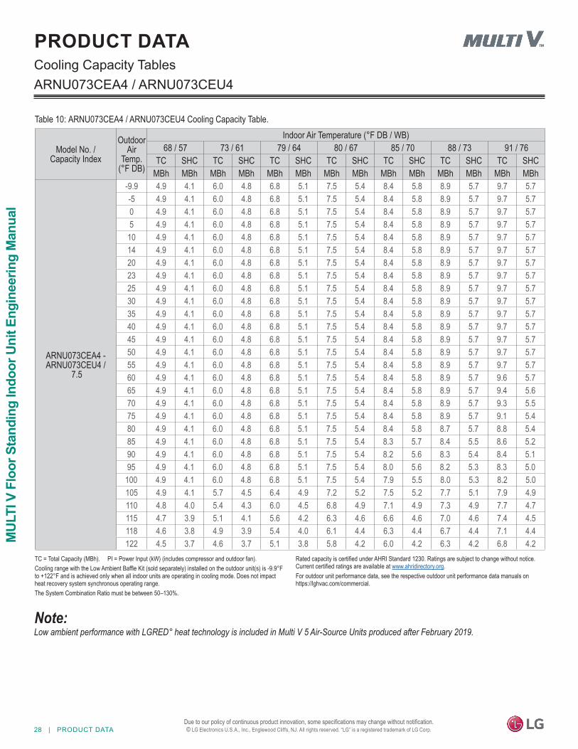
Cooling Capacity TablesPRODUCT DATA
Table 10: ARNU073CEA4 / ARNU073CEU4 Cooling Capacity Table.
ARNU073CEA4 / ARNU073CEU4
Model No. / Capacity Index
Outdoor Air
Temp. (°F DB)
Indoor Air Temperature (°F DB / WB)68 / 57 73 / 61 79 / 64 80 / 67 85 / 70 88 / 73 91 / 76
TC SHC TC SHC TC SHC TC SHC TC SHC TC SHC TC SHCMBh MBh MBh MBh MBh MBh MBh MBh MBh MBh MBh MBh MBh MBh
ARNU073CEA4 -ARNU073CEU4 /
7.5
-9.9 4.9 4.1 6.0 4.8 6.8 5.1 7.5 5.4 8.4 5.8 8.9 5.7 9.7 5.7 -5 4.9 4.1 6.0 4.8 6.8 5.1 7.5 5.4 8.4 5.8 8.9 5.7 9.7 5.7 0 4.9 4.1 6.0 4.8 6.8 5.1 7.5 5.4 8.4 5.8 8.9 5.7 9.7 5.7 5 4.9 4.1 6.0 4.8 6.8 5.1 7.5 5.4 8.4 5.8 8.9 5.7 9.7 5.7
10 4.9 4.1 6.0 4.8 6.8 5.1 7.5 5.4 8.4 5.8 8.9 5.7 9.7 5.7 14 4.9 4.1 6.0 4.8 6.8 5.1 7.5 5.4 8.4 5.8 8.9 5.7 9.7 5.7 20 4.9 4.1 6.0 4.8 6.8 5.1 7.5 5.4 8.4 5.8 8.9 5.7 9.7 5.7 23 4.9 4.1 6.0 4.8 6.8 5.1 7.5 5.4 8.4 5.8 8.9 5.7 9.7 5.7 25 4.9 4.1 6.0 4.8 6.8 5.1 7.5 5.4 8.4 5.8 8.9 5.7 9.7 5.7 30 4.9 4.1 6.0 4.8 6.8 5.1 7.5 5.4 8.4 5.8 8.9 5.7 9.7 5.7 35 4.9 4.1 6.0 4.8 6.8 5.1 7.5 5.4 8.4 5.8 8.9 5.7 9.7 5.7 40 4.9 4.1 6.0 4.8 6.8 5.1 7.5 5.4 8.4 5.8 8.9 5.7 9.7 5.7 45 4.9 4.1 6.0 4.8 6.8 5.1 7.5 5.4 8.4 5.8 8.9 5.7 9.7 5.7 50 4.9 4.1 6.0 4.8 6.8 5.1 7.5 5.4 8.4 5.8 8.9 5.7 9.7 5.7 55 4.9 4.1 6.0 4.8 6.8 5.1 7.5 5.4 8.4 5.8 8.9 5.7 9.7 5.7 60 4.9 4.1 6.0 4.8 6.8 5.1 7.5 5.4 8.4 5.8 8.9 5.7 9.6 5.7 65 4.9 4.1 6.0 4.8 6.8 5.1 7.5 5.4 8.4 5.8 8.9 5.7 9.4 5.6 70 4.9 4.1 6.0 4.8 6.8 5.1 7.5 5.4 8.4 5.8 8.9 5.7 9.3 5.5 75 4.9 4.1 6.0 4.8 6.8 5.1 7.5 5.4 8.4 5.8 8.9 5.7 9.1 5.4 80 4.9 4.1 6.0 4.8 6.8 5.1 7.5 5.4 8.4 5.8 8.7 5.7 8.8 5.4 85 4.9 4.1 6.0 4.8 6.8 5.1 7.5 5.4 8.3 5.7 8.4 5.5 8.6 5.2 90 4.9 4.1 6.0 4.8 6.8 5.1 7.5 5.4 8.2 5.6 8.3 5.4 8.4 5.1 95 4.9 4.1 6.0 4.8 6.8 5.1 7.5 5.4 8.0 5.6 8.2 5.3 8.3 5.0
100 4.9 4.1 6.0 4.8 6.8 5.1 7.5 5.4 7.9 5.5 8.0 5.3 8.2 5.0 105 4.9 4.1 5.7 4.5 6.4 4.9 7.2 5.2 7.5 5.2 7.7 5.1 7.9 4.9 110 4.8 4.0 5.4 4.3 6.0 4.5 6.8 4.9 7.1 4.9 7.3 4.9 7.7 4.7 115 4.7 3.9 5.1 4.1 5.6 4.2 6.3 4.6 6.6 4.6 7.0 4.6 7.4 4.5 118 4.6 3.8 4.9 3.9 5.4 4.0 6.1 4.4 6.3 4.4 6.7 4.4 7.1 4.4 122 4.5 3.7 4.6 3.7 5.1 3.8 5.8 4.2 6.0 4.2 6.3 4.2 6.8 4.2
Low ambient performance with LGRED° heat technology is included in Multi V 5 Air-Source Units produced after February 2019.
TC = Total Capacity (MBh). PI = Power Input (kW) (includes compressor and outdoor fan).Cooling range with the Low Ambient Baffle Kit (sold separately) installed on the outdoor unit(s) is -9.9°F to +122°F and is achieved only when all indoor units are operating in cooling mode. Does not impact heat recovery system synchronous operating range.The System Combination Ratio must be between 50–130%.
Rated capacity is certified under AHRI Standard 1230. Ratings are subject to change without notice. Current certified ratings are available at www.ahridirectory.org.For outdoor unit performance data, see the respective outdoor unit performance data manuals on https://lghvac.com/commercial.
PRODUCT DATA | 29
Product Data
Due to our policy of continuous product innovation, some specifications may change without notification. © LG Electronics U.S.A., Inc., Englewood Cliffs, NJ. All rights reserved. “LG” is a registered trademark of LG Corp.
Model No. / Capacity Index
Outdoor Air
Temp. (°F DB)
Indoor Air Temperature (°F DB / WB)68 / 57 73 / 61 79 / 64 80 / 67 85 / 70 88 / 73 91 / 76
TC SHC TC SHC TC SHC TC SHC TC SHC TC SHC TC SHCMBh MBh MBh MBh MBh MBh MBh MBh MBh MBh MBh MBh MBh MBh
ARNU093CEA4 -ARNU093CEU4 /
9.6
-9.9 6.3 5.3 7.7 6.1 8.6 6.5 9.6 6.9 10.8 7.4 11.4 7.3 12.4 7.3 -5 6.3 5.3 7.7 6.1 8.6 6.5 9.6 6.9 10.8 7.4 11.4 7.3 12.4 7.3 0 6.3 5.3 7.7 6.1 8.6 6.5 9.6 6.9 10.8 7.4 11.4 7.3 12.4 7.3 5 6.3 5.3 7.7 6.1 8.6 6.5 9.6 6.9 10.8 7.4 11.4 7.3 12.4 7.3
10 6.3 5.3 7.7 6.1 8.6 6.5 9.6 6.9 10.8 7.4 11.4 7.3 12.4 7.3 14 6.3 5.3 7.7 6.1 8.6 6.5 9.6 6.9 10.8 7.4 11.4 7.3 12.4 7.3 20 6.3 5.3 7.7 6.1 8.6 6.5 9.6 6.9 10.8 7.4 11.4 7.3 12.4 7.3 23 6.3 5.3 7.7 6.1 8.6 6.5 9.6 6.9 10.8 7.4 11.4 7.3 12.4 7.3 25 6.3 5.3 7.7 6.1 8.6 6.5 9.6 6.9 10.8 7.4 11.4 7.3 12.4 7.3 30 6.3 5.3 7.7 6.1 8.6 6.5 9.6 6.9 10.8 7.4 11.4 7.3 12.4 7.3 35 6.3 5.3 7.7 6.1 8.6 6.5 9.6 6.9 10.8 7.4 11.4 7.3 12.4 7.3 40 6.3 5.3 7.7 6.1 8.6 6.5 9.6 6.9 10.8 7.4 11.4 7.3 12.4 7.3 45 6.3 5.3 7.7 6.1 8.6 6.5 9.6 6.9 10.8 7.4 11.4 7.3 12.4 7.3 50 6.3 5.3 7.7 6.1 8.6 6.5 9.6 6.9 10.8 7.4 11.4 7.3 12.4 7.3 55 6.3 5.3 7.7 6.1 8.6 6.5 9.6 6.9 10.8 7.4 11.4 7.3 12.4 7.3 60 6.3 5.3 7.7 6.1 8.6 6.5 9.6 6.9 10.8 7.4 11.4 7.3 12.3 7.3 65 6.3 5.3 7.7 6.1 8.6 6.5 9.6 6.9 10.8 7.4 11.4 7.3 12.1 7.2 70 6.3 5.3 7.7 6.1 8.6 6.5 9.6 6.9 10.8 7.4 11.4 7.3 11.9 7.1 75 6.3 5.3 7.7 6.1 8.6 6.5 9.6 6.9 10.8 7.4 11.4 7.3 11.6 6.9 80 6.3 5.3 7.7 6.1 8.6 6.5 9.6 6.9 10.8 7.4 11.1 7.3 11.3 6.9 85 6.3 5.3 7.7 6.1 8.6 6.5 9.6 6.9 10.6 7.3 10.8 7.0 11.0 6.6 90 6.3 5.3 7.7 6.1 8.6 6.5 9.6 6.9 10.5 7.2 10.6 6.9 10.8 6.5 95 6.3 5.3 7.7 6.1 8.6 6.5 9.6 6.9 10.3 7.2 10.5 6.8 10.6 6.4
100 6.3 5.3 7.7 6.1 8.6 6.5 9.6 6.9 10.1 7.1 10.3 6.7 10.5 6.4 105 6.3 5.3 7.3 5.8 8.2 6.2 9.2 6.6 9.6 6.6 9.9 6.5 10.2 6.2 110 6.2 5.1 6.9 5.5 7.7 5.8 8.6 6.2 9.0 6.2 9.4 6.2 9.8 6.0 115 6.0 5.0 6.6 5.2 7.2 5.4 8.1 5.9 8.5 5.9 8.9 5.9 9.4 5.8 118 5.9 4.8 6.2 4.9 6.9 5.1 7.8 5.6 8.1 5.6 8.5 5.6 9.0 5.6 122 5.7 4.7 5.9 4.7 6.5 4.8 7.4 5.3 7.7 5.3 8.1 5.3 8.7 5.3
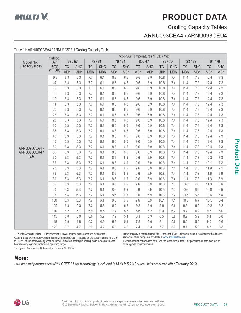
Table 11: ARNU093CEA4 / ARNU093CEU Cooling Capacity Table.
ARNU093CEA4 / ARNU093CEU4Cooling Capacity Tables
PRODUCT DATA
Low ambient performance with LGRED° heat technology is included in Multi V 5 Air-Source Units produced after February 2019.
TC = Total Capacity (MBh). PI = Power Input (kW) (includes compressor and outdoor fan).Cooling range with the Low Ambient Baffle Kit (sold separately) installed on the outdoor unit(s) is -9.9°F to +122°F and is achieved only when all indoor units are operating in cooling mode. Does not impact heat recovery system synchronous operating range.The System Combination Ratio must be between 50–130%.
Rated capacity is certified under AHRI Standard 1230. Ratings are subject to change without notice. Current certified ratings are available at www.ahridirectory.org.For outdoor unit performance data, see the respective outdoor unit performance data manuals on https://lghvac.com/commercial.
30 | PRODUCT DATA
MUL
TI V
Flo
or S
tand
ing
Indo
or U
nit E
ngin
eerin
g M
anua
l
Due to our policy of continuous product innovation, some specifications may change without notification. © LG Electronics U.S.A., Inc., Englewood Cliffs, NJ. All rights reserved. “LG” is a registered trademark of LG Corp.
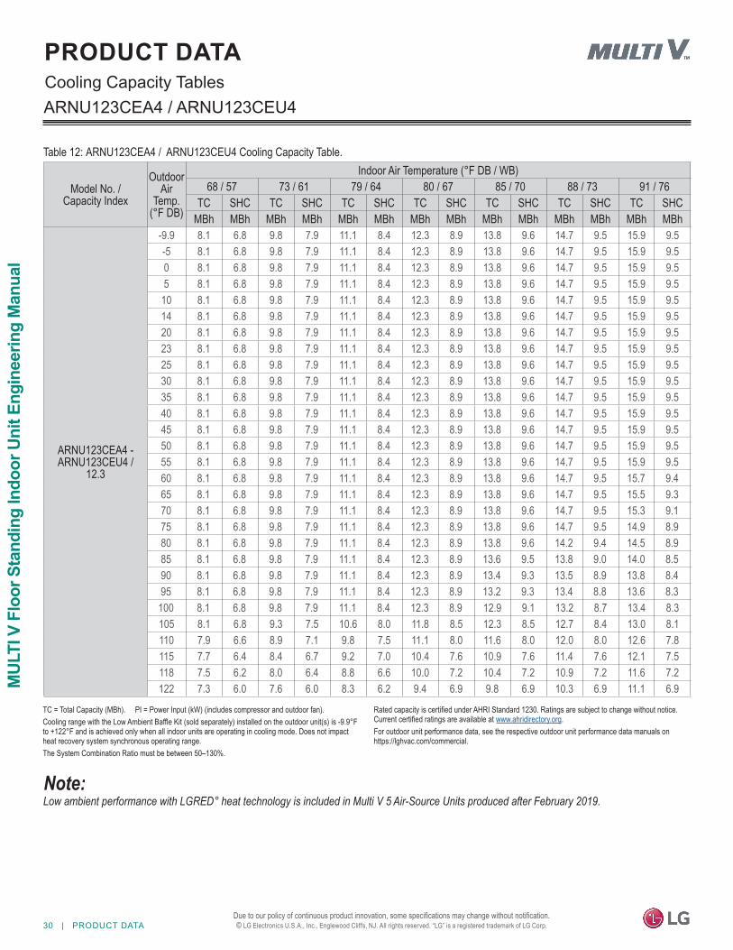
ARNU123CEA4 / ARNU123CEU4
Table 12: ARNU123CEA4 / ARNU123CEU4 Cooling Capacity Table.
Model No. / Capacity Index
Outdoor Air
Temp. (°F DB)
Indoor Air Temperature (°F DB / WB)68 / 57 73 / 61 79 / 64 80 / 67 85 / 70 88 / 73 91 / 76
TC SHC TC SHC TC SHC TC SHC TC SHC TC SHC TC SHCMBh MBh MBh MBh MBh MBh MBh MBh MBh MBh MBh MBh MBh MBh
ARNU123CEA4 -ARNU123CEU4 /
12.3
-9.9 8.1 6.8 9.8 7.9 11.1 8.4 12.3 8.9 13.8 9.6 14.7 9.5 15.9 9.5 -5 8.1 6.8 9.8 7.9 11.1 8.4 12.3 8.9 13.8 9.6 14.7 9.5 15.9 9.5 0 8.1 6.8 9.8 7.9 11.1 8.4 12.3 8.9 13.8 9.6 14.7 9.5 15.9 9.5 5 8.1 6.8 9.8 7.9 11.1 8.4 12.3 8.9 13.8 9.6 14.7 9.5 15.9 9.5
10 8.1 6.8 9.8 7.9 11.1 8.4 12.3 8.9 13.8 9.6 14.7 9.5 15.9 9.5 14 8.1 6.8 9.8 7.9 11.1 8.4 12.3 8.9 13.8 9.6 14.7 9.5 15.9 9.5 20 8.1 6.8 9.8 7.9 11.1 8.4 12.3 8.9 13.8 9.6 14.7 9.5 15.9 9.5 23 8.1 6.8 9.8 7.9 11.1 8.4 12.3 8.9 13.8 9.6 14.7 9.5 15.9 9.5 25 8.1 6.8 9.8 7.9 11.1 8.4 12.3 8.9 13.8 9.6 14.7 9.5 15.9 9.5 30 8.1 6.8 9.8 7.9 11.1 8.4 12.3 8.9 13.8 9.6 14.7 9.5 15.9 9.5 35 8.1 6.8 9.8 7.9 11.1 8.4 12.3 8.9 13.8 9.6 14.7 9.5 15.9 9.5 40 8.1 6.8 9.8 7.9 11.1 8.4 12.3 8.9 13.8 9.6 14.7 9.5 15.9 9.5 45 8.1 6.8 9.8 7.9 11.1 8.4 12.3 8.9 13.8 9.6 14.7 9.5 15.9 9.5 50 8.1 6.8 9.8 7.9 11.1 8.4 12.3 8.9 13.8 9.6 14.7 9.5 15.9 9.5 55 8.1 6.8 9.8 7.9 11.1 8.4 12.3 8.9 13.8 9.6 14.7 9.5 15.9 9.5 60 8.1 6.8 9.8 7.9 11.1 8.4 12.3 8.9 13.8 9.6 14.7 9.5 15.7 9.4 65 8.1 6.8 9.8 7.9 11.1 8.4 12.3 8.9 13.8 9.6 14.7 9.5 15.5 9.3 70 8.1 6.8 9.8 7.9 11.1 8.4 12.3 8.9 13.8 9.6 14.7 9.5 15.3 9.1 75 8.1 6.8 9.8 7.9 11.1 8.4 12.3 8.9 13.8 9.6 14.7 9.5 14.9 8.9 80 8.1 6.8 9.8 7.9 11.1 8.4 12.3 8.9 13.8 9.6 14.2 9.4 14.5 8.9 85 8.1 6.8 9.8 7.9 11.1 8.4 12.3 8.9 13.6 9.5 13.8 9.0 14.0 8.5 90 8.1 6.8 9.8 7.9 11.1 8.4 12.3 8.9 13.4 9.3 13.5 8.9 13.8 8.4 95 8.1 6.8 9.8 7.9 11.1 8.4 12.3 8.9 13.2 9.3 13.4 8.8 13.6 8.3
100 8.1 6.8 9.8 7.9 11.1 8.4 12.3 8.9 12.9 9.1 13.2 8.7 13.4 8.3 105 8.1 6.8 9.3 7.5 10.6 8.0 11.8 8.5 12.3 8.5 12.7 8.4 13.0 8.1 110 7.9 6.6 8.9 7.1 9.8 7.5 11.1 8.0 11.6 8.0 12.0 8.0 12.6 7.8 115 7.7 6.4 8.4 6.7 9.2 7.0 10.4 7.6 10.9 7.6 11.4 7.6 12.1 7.5 118 7.5 6.2 8.0 6.4 8.8 6.6 10.0 7.2 10.4 7.2 10.9 7.2 11.6 7.2 122 7.3 6.0 7.6 6.0 8.3 6.2 9.4 6.9 9.8 6.9 10.3 6.9 11.1 6.9
Cooling Capacity TablesPRODUCT DATA
Low ambient performance with LGRED° heat technology is included in Multi V 5 Air-Source Units produced after February 2019.
TC = Total Capacity (MBh). PI = Power Input (kW) (includes compressor and outdoor fan).Cooling range with the Low Ambient Baffle Kit (sold separately) installed on the outdoor unit(s) is -9.9°F to +122°F and is achieved only when all indoor units are operating in cooling mode. Does not impact heat recovery system synchronous operating range.The System Combination Ratio must be between 50–130%.
Rated capacity is certified under AHRI Standard 1230. Ratings are subject to change without notice. Current certified ratings are available at www.ahridirectory.org.For outdoor unit performance data, see the respective outdoor unit performance data manuals on https://lghvac.com/commercial.
PRODUCT DATA | 31
Product Data
Due to our policy of continuous product innovation, some specifications may change without notification. © LG Electronics U.S.A., Inc., Englewood Cliffs, NJ. All rights reserved. “LG” is a registered trademark of LG Corp.
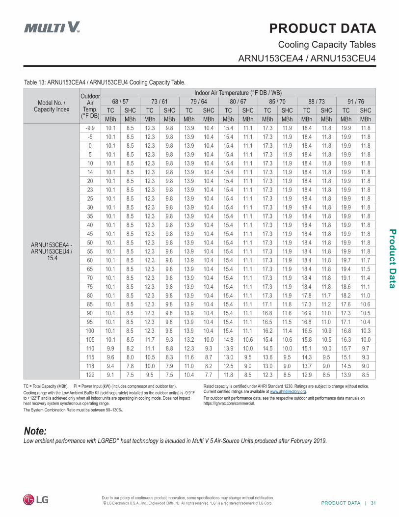
Cooling Capacity Tables
Table 13: ARNU153CEA4 / ARNU153CEU4 Cooling Capacity Table.
ARNU153CEA4 / ARNU153CEU4
PRODUCT DATA
Model No. / Capacity Index
Outdoor Air
Temp. (°F DB)
Indoor Air Temperature (°F DB / WB)68 / 57 73 / 61 79 / 64 80 / 67 85 / 70 88 / 73 91 / 76
TC SHC TC SHC TC SHC TC SHC TC SHC TC SHC TC SHCMBh MBh MBh MBh MBh MBh MBh MBh MBh MBh MBh MBh MBh MBh
ARNU153CEA4 -ARNU153CEU4 /
15.4
-9.9 10.1 8.5 12.3 9.8 13.9 10.4 15.4 11.1 17.3 11.9 18.4 11.8 19.9 11.8 -5 10.1 8.5 12.3 9.8 13.9 10.4 15.4 11.1 17.3 11.9 18.4 11.8 19.9 11.8 0 10.1 8.5 12.3 9.8 13.9 10.4 15.4 11.1 17.3 11.9 18.4 11.8 19.9 11.8 5 10.1 8.5 12.3 9.8 13.9 10.4 15.4 11.1 17.3 11.9 18.4 11.8 19.9 11.8
10 10.1 8.5 12.3 9.8 13.9 10.4 15.4 11.1 17.3 11.9 18.4 11.8 19.9 11.8 14 10.1 8.5 12.3 9.8 13.9 10.4 15.4 11.1 17.3 11.9 18.4 11.8 19.9 11.8 20 10.1 8.5 12.3 9.8 13.9 10.4 15.4 11.1 17.3 11.9 18.4 11.8 19.9 11.8 23 10.1 8.5 12.3 9.8 13.9 10.4 15.4 11.1 17.3 11.9 18.4 11.8 19.9 11.8 25 10.1 8.5 12.3 9.8 13.9 10.4 15.4 11.1 17.3 11.9 18.4 11.8 19.9 11.8 30 10.1 8.5 12.3 9.8 13.9 10.4 15.4 11.1 17.3 11.9 18.4 11.8 19.9 11.8 35 10.1 8.5 12.3 9.8 13.9 10.4 15.4 11.1 17.3 11.9 18.4 11.8 19.9 11.8 40 10.1 8.5 12.3 9.8 13.9 10.4 15.4 11.1 17.3 11.9 18.4 11.8 19.9 11.8 45 10.1 8.5 12.3 9.8 13.9 10.4 15.4 11.1 17.3 11.9 18.4 11.8 19.9 11.8 50 10.1 8.5 12.3 9.8 13.9 10.4 15.4 11.1 17.3 11.9 18.4 11.8 19.9 11.8 55 10.1 8.5 12.3 9.8 13.9 10.4 15.4 11.1 17.3 11.9 18.4 11.8 19.9 11.8 60 10.1 8.5 12.3 9.8 13.9 10.4 15.4 11.1 17.3 11.9 18.4 11.8 19.7 11.7 65 10.1 8.5 12.3 9.8 13.9 10.4 15.4 11.1 17.3 11.9 18.4 11.8 19.4 11.5 70 10.1 8.5 12.3 9.8 13.9 10.4 15.4 11.1 17.3 11.9 18.4 11.8 19.1 11.4 75 10.1 8.5 12.3 9.8 13.9 10.4 15.4 11.1 17.3 11.9 18.4 11.8 18.6 11.1 80 10.1 8.5 12.3 9.8 13.9 10.4 15.4 11.1 17.3 11.9 17.8 11.7 18.2 11.0 85 10.1 8.5 12.3 9.8 13.9 10.4 15.4 11.1 17.1 11.8 17.3 11.2 17.6 10.6 90 10.1 8.5 12.3 9.8 13.9 10.4 15.4 11.1 16.8 11.6 16.9 11.0 17.3 10.5 95 10.1 8.5 12.3 9.8 13.9 10.4 15.4 11.1 16.5 11.5 16.8 11.0 17.1 10.4
100 10.1 8.5 12.3 9.8 13.9 10.4 15.4 11.1 16.2 11.4 16.5 10.9 16.8 10.3 105 10.1 8.5 11.7 9.3 13.2 10.0 14.8 10.6 15.4 10.6 15.8 10.5 16.3 10.0 110 9.9 8.2 11.1 8.8 12.3 9.3 13.9 10.0 14.5 10.0 15.1 10.0 15.7 9.7 115 9.6 8.0 10.5 8.3 11.6 8.7 13.0 9.5 13.6 9.5 14.3 9.5 15.1 9.3 118 9.4 7.8 10.0 7.9 11.0 8.2 12.5 9.0 13.0 9.0 13.7 9.0 14.5 9.0 122 9.1 7.5 9.5 7.5 10.4 7.7 11.8 8.5 12.3 8.5 12.9 8.5 13.9 8.5
Low ambient performance with LGRED° heat technology is included in Multi V 5 Air-Source Units produced after February 2019.
TC = Total Capacity (MBh). PI = Power Input (kW) (includes compressor and outdoor fan).Cooling range with the Low Ambient Baffle Kit (sold separately) installed on the outdoor unit(s) is -9.9°F to +122°F and is achieved only when all indoor units are operating in cooling mode. Does not impact heat recovery system synchronous operating range.The System Combination Ratio must be between 50–130%.
Rated capacity is certified under AHRI Standard 1230. Ratings are subject to change without notice. Current certified ratings are available at www.ahridirectory.org.For outdoor unit performance data, see the respective outdoor unit performance data manuals on https://lghvac.com/commercial.
32 | PRODUCT DATA
MUL
TI V
Flo
or S
tand
ing
Indo
or U
nit E
ngin
eerin
g M
anua
l
Due to our policy of continuous product innovation, some specifications may change without notification. © LG Electronics U.S.A., Inc., Englewood Cliffs, NJ. All rights reserved. “LG” is a registered trademark of LG Corp.
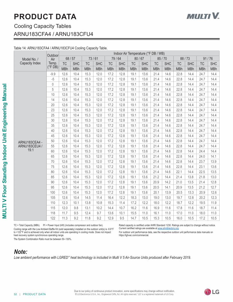
ARNU183CFA4 / ARNU183CFU4
Table 14: ARNU183CFA4 / ARNU183CFU4 Cooling Capacity Table.
Cooling Capacity TablesPRODUCT DATA
Model No. / Capacity Index
Outdoor Air
Temp. (°F DB)
Indoor Air Temperature (°F DB / WB)68 / 57 73 / 61 79 / 64 80 / 67 85 / 70 88 / 73 91 / 76
TC SHC TC SHC TC SHC TC SHC TC SHC TC SHC TC SHCMBh MBh MBh MBh MBh MBh MBh MBh MBh MBh MBh MBh MBh MBh
ARNU183CEA4 -ARNU183CEU4 /
19.1
-9.9 12.6 10.4 15.3 12.0 17.2 12.8 19.1 13.6 21.4 14.6 22.8 14.4 24.7 14.4 -5 12.6 10.4 15.3 12.0 17.2 12.8 19.1 13.6 21.4 14.6 22.8 14.4 24.7 14.4 0 12.6 10.4 15.3 12.0 17.2 12.8 19.1 13.6 21.4 14.6 22.8 14.4 24.7 14.4 5 12.6 10.4 15.3 12.0 17.2 12.8 19.1 13.6 21.4 14.6 22.8 14.4 24.7 14.4
10 12.6 10.4 15.3 12.0 17.2 12.8 19.1 13.6 21.4 14.6 22.8 14.4 24.7 14.4 14 12.6 10.4 15.3 12.0 17.2 12.8 19.1 13.6 21.4 14.6 22.8 14.4 24.7 14.4 20 12.6 10.4 15.3 12.0 17.2 12.8 19.1 13.6 21.4 14.6 22.8 14.4 24.7 14.4 23 12.6 10.4 15.3 12.0 17.2 12.8 19.1 13.6 21.4 14.6 22.8 14.4 24.7 14.4 25 12.6 10.4 15.3 12.0 17.2 12.8 19.1 13.6 21.4 14.6 22.8 14.4 24.7 14.4 30 12.6 10.4 15.3 12.0 17.2 12.8 19.1 13.6 21.4 14.6 22.8 14.4 24.7 14.4 35 12.6 10.4 15.3 12.0 17.2 12.8 19.1 13.6 21.4 14.6 22.8 14.4 24.7 14.4 40 12.6 10.4 15.3 12.0 17.2 12.8 19.1 13.6 21.4 14.6 22.8 14.4 24.7 14.4 45 12.6 10.4 15.3 12.0 17.2 12.8 19.1 13.6 21.4 14.6 22.8 14.4 24.7 14.4 50 12.6 10.4 15.3 12.0 17.2 12.8 19.1 13.6 21.4 14.6 22.8 14.4 24.7 14.4 55 12.6 10.4 15.3 12.0 17.2 12.8 19.1 13.6 21.4 14.6 22.8 14.4 24.7 14.4 60 12.6 10.4 15.3 12.0 17.2 12.8 19.1 13.6 21.4 14.6 22.8 14.4 24.4 14.4 65 12.6 10.4 15.3 12.0 17.2 12.8 19.1 13.6 21.4 14.6 22.8 14.4 24.0 14.1 70 12.6 10.4 15.3 12.0 17.2 12.8 19.1 13.6 21.4 14.6 22.8 14.4 23.7 13.9 75 12.6 10.4 15.3 12.0 17.2 12.8 19.1 13.6 21.4 14.6 22.8 14.4 23.1 13.6 80 12.6 10.4 15.3 12.0 17.2 12.8 19.1 13.6 21.4 14.6 22.1 14.4 22.5 13.5 85 12.6 10.4 15.3 12.0 17.2 12.8 19.1 13.6 21.2 14.4 21.4 13.8 21.8 13.0 90 12.6 10.4 15.3 12.0 17.2 12.8 19.1 13.6 20.9 14.2 21.0 13.5 21.4 12.8 95 12.6 10.4 15.3 12.0 17.2 12.8 19.1 13.6 20.5 14.1 20.9 13.5 21.2 12.7
100 12.6 10.4 15.3 12.0 17.2 12.8 19.1 13.6 20.1 13.9 20.5 13.3 20.9 12.6 105 12.6 10.4 14.5 11.4 16.4 12.2 18.3 13.0 19.0 13.0 19.7 12.8 20.2 12.3 110 12.3 10.1 13.8 10.8 15.3 11.4 17.2 12.2 18.0 12.2 18.7 12.2 19.5 11.9 115 12.0 9.8 13.1 10.2 14.4 10.7 16.2 11.6 16.9 11.6 17.8 11.6 18.7 11.4 118 11.7 9.5 12.4 9.7 13.6 10.1 15.5 11.0 16.1 11.0 17.0 11.0 18.0 11.0 122 11.3 9.2 11.8 9.2 12.9 9.5 14.7 10.5 15.3 10.5 16.0 10.5 17.2 10.5
Low ambient performance with LGRED° heat technology is included in Multi V 5 Air-Source Units produced after February 2019.
TC = Total Capacity (MBh). PI = Power Input (kW) (includes compressor and outdoor fan).Cooling range with the Low Ambient Baffle Kit (sold separately) installed on the outdoor unit(s) is -9.9°F to +122°F and is achieved only when all indoor units are operating in cooling mode. Does not impact heat recovery system synchronous operating range.The System Combination Ratio must be between 50–130%.
Rated capacity is certified under AHRI Standard 1230. Ratings are subject to change without notice. Current certified ratings are available at www.ahridirectory.org.For outdoor unit performance data, see the respective outdoor unit performance data manuals on https://lghvac.com/commercial.
PRODUCT DATA | 33
Product Data
Due to our policy of continuous product innovation, some specifications may change without notification. © LG Electronics U.S.A., Inc., Englewood Cliffs, NJ. All rights reserved. “LG” is a registered trademark of LG Corp.
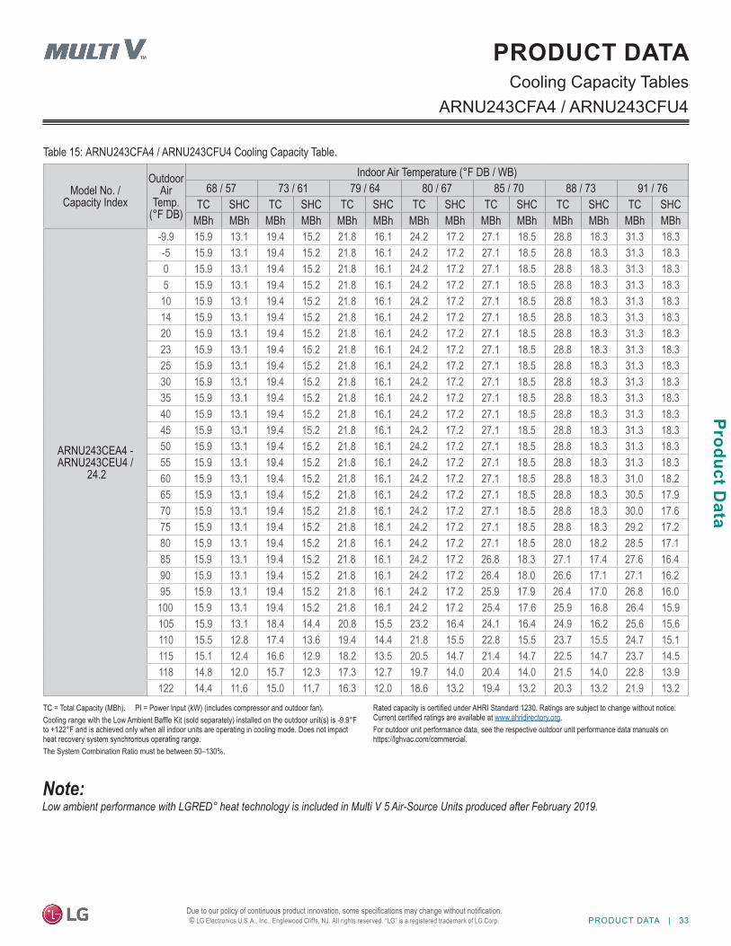
ARNU243CFA4 / ARNU243CFU4
Table 15: ARNU243CFA4 / ARNU243CFU4 Cooling Capacity Table.
Model No. / Capacity Index
Outdoor Air
Temp. (°F DB)
Indoor Air Temperature (°F DB / WB)68 / 57 73 / 61 79 / 64 80 / 67 85 / 70 88 / 73 91 / 76
TC SHC TC SHC TC SHC TC SHC TC SHC TC SHC TC SHCMBh MBh MBh MBh MBh MBh MBh MBh MBh MBh MBh MBh MBh MBh
ARNU243CEA4 -ARNU243CEU4 /
24.2
-9.9 15.9 13.1 19.4 15.2 21.8 16.1 24.2 17.2 27.1 18.5 28.8 18.3 31.3 18.3 -5 15.9 13.1 19.4 15.2 21.8 16.1 24.2 17.2 27.1 18.5 28.8 18.3 31.3 18.3 0 15.9 13.1 19.4 15.2 21.8 16.1 24.2 17.2 27.1 18.5 28.8 18.3 31.3 18.3 5 15.9 13.1 19.4 15.2 21.8 16.1 24.2 17.2 27.1 18.5 28.8 18.3 31.3 18.3
10 15.9 13.1 19.4 15.2 21.8 16.1 24.2 17.2 27.1 18.5 28.8 18.3 31.3 18.3 14 15.9 13.1 19.4 15.2 21.8 16.1 24.2 17.2 27.1 18.5 28.8 18.3 31.3 18.3 20 15.9 13.1 19.4 15.2 21.8 16.1 24.2 17.2 27.1 18.5 28.8 18.3 31.3 18.3 23 15.9 13.1 19.4 15.2 21.8 16.1 24.2 17.2 27.1 18.5 28.8 18.3 31.3 18.3 25 15.9 13.1 19.4 15.2 21.8 16.1 24.2 17.2 27.1 18.5 28.8 18.3 31.3 18.3 30 15.9 13.1 19.4 15.2 21.8 16.1 24.2 17.2 27.1 18.5 28.8 18.3 31.3 18.3 35 15.9 13.1 19.4 15.2 21.8 16.1 24.2 17.2 27.1 18.5 28.8 18.3 31.3 18.3 40 15.9 13.1 19.4 15.2 21.8 16.1 24.2 17.2 27.1 18.5 28.8 18.3 31.3 18.3 45 15.9 13.1 19.4 15.2 21.8 16.1 24.2 17.2 27.1 18.5 28.8 18.3 31.3 18.3 50 15.9 13.1 19.4 15.2 21.8 16.1 24.2 17.2 27.1 18.5 28.8 18.3 31.3 18.3 55 15.9 13.1 19.4 15.2 21.8 16.1 24.2 17.2 27.1 18.5 28.8 18.3 31.3 18.3 60 15.9 13.1 19.4 15.2 21.8 16.1 24.2 17.2 27.1 18.5 28.8 18.3 31.0 18.2 65 15.9 13.1 19.4 15.2 21.8 16.1 24.2 17.2 27.1 18.5 28.8 18.3 30.5 17.9 70 15.9 13.1 19.4 15.2 21.8 16.1 24.2 17.2 27.1 18.5 28.8 18.3 30.0 17.6 75 15.9 13.1 19.4 15.2 21.8 16.1 24.2 17.2 27.1 18.5 28.8 18.3 29.2 17.2 80 15.9 13.1 19.4 15.2 21.8 16.1 24.2 17.2 27.1 18.5 28.0 18.2 28.5 17.1 85 15.9 13.1 19.4 15.2 21.8 16.1 24.2 17.2 26.8 18.3 27.1 17.4 27.6 16.4 90 15.9 13.1 19.4 15.2 21.8 16.1 24.2 17.2 26.4 18.0 26.6 17.1 27.1 16.2 95 15.9 13.1 19.4 15.2 21.8 16.1 24.2 17.2 25.9 17.9 26.4 17.0 26.8 16.0
100 15.9 13.1 19.4 15.2 21.8 16.1 24.2 17.2 25.4 17.6 25.9 16.8 26.4 15.9 105 15.9 13.1 18.4 14.4 20.8 15.5 23.2 16.4 24.1 16.4 24.9 16.2 25.6 15.6 110 15.5 12.8 17.4 13.6 19.4 14.4 21.8 15.5 22.8 15.5 23.7 15.5 24.7 15.1 115 15.1 12.4 16.6 12.9 18.2 13.5 20.5 14.7 21.4 14.7 22.5 14.7 23.7 14.5 118 14.8 12.0 15.7 12.3 17.3 12.7 19.7 14.0 20.4 14.0 21.5 14.0 22.8 13.9 122 14.4 11.6 15.0 11.7 16.3 12.0 18.6 13.2 19.4 13.2 20.3 13.2 21.9 13.2
Cooling Capacity TablesPRODUCT DATA
Low ambient performance with LGRED° heat technology is included in Multi V 5 Air-Source Units produced after February 2019.
TC = Total Capacity (MBh). PI = Power Input (kW) (includes compressor and outdoor fan).Cooling range with the Low Ambient Baffle Kit (sold separately) installed on the outdoor unit(s) is -9.9°F to +122°F and is achieved only when all indoor units are operating in cooling mode. Does not impact heat recovery system synchronous operating range.The System Combination Ratio must be between 50–130%.
Rated capacity is certified under AHRI Standard 1230. Ratings are subject to change without notice. Current certified ratings are available at www.ahridirectory.org.For outdoor unit performance data, see the respective outdoor unit performance data manuals on https://lghvac.com/commercial.
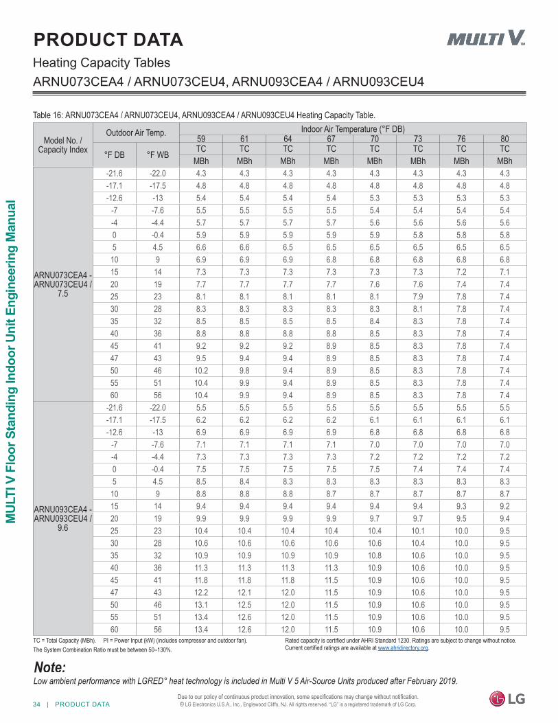
34 | PRODUCT DATA
MUL
TI V
Flo
or S
tand
ing
Indo
or U
nit E
ngin
eerin
g M
anua
l
Due to our policy of continuous product innovation, some specifications may change without notification. © LG Electronics U.S.A., Inc., Englewood Cliffs, NJ. All rights reserved. “LG” is a registered trademark of LG Corp.
Heating Capacity Tables
Table 16: ARNU073CEA4 / ARNU073CEU4, ARNU093CEA4 / ARNU093CEU4 Heating Capacity Table.
Model No. / Capacity Index
Outdoor Air Temp. Indoor Air Temperature (°F DB)59 61 64 67 70 73 76 80
°F DB °F WB TC TC TC TC TC TC TC TCMBh MBh MBh MBh MBh MBh MBh MBh
ARNU073CEA4 -ARNU073CEU4 /
7.5
-21.6 -22.0 4.3 4.3 4.3 4.3 4.3 4.3 4.3 4.3-17.1 -17.5 4.8 4.8 4.8 4.8 4.8 4.8 4.8 4.8-12.6 -13 5.4 5.4 5.4 5.4 5.3 5.3 5.3 5.3
-7 -7.6 5.5 5.5 5.5 5.5 5.4 5.4 5.4 5.4-4 -4.4 5.7 5.7 5.7 5.7 5.6 5.6 5.6 5.60 -0.4 5.9 5.9 5.9 5.9 5.9 5.8 5.8 5.85 4.5 6.6 6.6 6.5 6.5 6.5 6.5 6.5 6.5
10 9 6.9 6.9 6.9 6.8 6.8 6.8 6.8 6.815 14 7.3 7.3 7.3 7.3 7.3 7.3 7.2 7.120 19 7.7 7.7 7.7 7.7 7.6 7.6 7.4 7.425 23 8.1 8.1 8.1 8.1 8.1 7.9 7.8 7.430 28 8.3 8.3 8.3 8.3 8.3 8.1 7.8 7.435 32 8.5 8.5 8.5 8.5 8.4 8.3 7.8 7.440 36 8.8 8.8 8.8 8.8 8.5 8.3 7.8 7.445 41 9.2 9.2 9.2 8.9 8.5 8.3 7.8 7.447 43 9.5 9.4 9.4 8.9 8.5 8.3 7.8 7.450 46 10.2 9.8 9.4 8.9 8.5 8.3 7.8 7.455 51 10.4 9.9 9.4 8.9 8.5 8.3 7.8 7.460 56 10.4 9.9 9.4 8.9 8.5 8.3 7.8 7.4
ARNU093CEA4 -ARNU093CEU4 /
9.6
-21.6 -22.0 5.5 5.5 5.5 5.5 5.5 5.5 5.5 5.5-17.1 -17.5 6.2 6.2 6.2 6.2 6.1 6.1 6.1 6.1-12.6 -13 6.9 6.9 6.9 6.9 6.8 6.8 6.8 6.8
-7 -7.6 7.1 7.1 7.1 7.1 7.0 7.0 7.0 7.0-4 -4.4 7.3 7.3 7.3 7.3 7.2 7.2 7.2 7.20 -0.4 7.5 7.5 7.5 7.5 7.5 7.4 7.4 7.45 4.5 8.5 8.4 8.3 8.3 8.3 8.3 8.3 8.3
10 9 8.8 8.8 8.8 8.7 8.7 8.7 8.7 8.715 14 9.4 9.4 9.4 9.4 9.4 9.4 9.3 9.220 19 9.9 9.9 9.9 9.9 9.7 9.7 9.5 9.425 23 10.4 10.4 10.4 10.4 10.4 10.1 10.0 9.530 28 10.6 10.6 10.6 10.6 10.6 10.4 10.0 9.535 32 10.9 10.9 10.9 10.9 10.8 10.6 10.0 9.540 36 11.3 11.3 11.3 11.3 10.9 10.6 10.0 9.545 41 11.8 11.8 11.8 11.5 10.9 10.6 10.0 9.547 43 12.2 12.1 12.0 11.5 10.9 10.6 10.0 9.550 46 13.1 12.5 12.0 11.5 10.9 10.6 10.0 9.555 51 13.4 12.6 12.0 11.5 10.9 10.6 10.0 9.560 56 13.4 12.6 12.0 11.5 10.9 10.6 10.0 9.5
PRODUCT DATA
ARNU073CEA4 / ARNU073CEU4, ARNU093CEA4 / ARNU093CEU4
Low ambient performance with LGRED° heat technology is included in Multi V 5 Air-Source Units produced after February 2019.
TC = Total Capacity (MBh). PI = Power Input (kW) (includes compressor and outdoor fan).The System Combination Ratio must be between 50–130%.
Rated capacity is certified under AHRI Standard 1230. Ratings are subject to change without notice. Current certified ratings are available at www.ahridirectory.org.
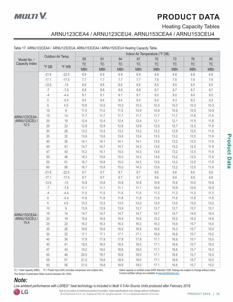
PRODUCT DATA | 35
Product Data
Due to our policy of continuous product innovation, some specifications may change without notification. © LG Electronics U.S.A., Inc., Englewood Cliffs, NJ. All rights reserved. “LG” is a registered trademark of LG Corp.
Heating Capacity TablesPRODUCT DATA
Model No. / Capacity Index
Outdoor Air Temp. Indoor Air Temperature (°F DB)59 61 64 67 70 73 76 80
°F DB °F WB TC TC TC TC TC TC TC TCMBh MBh MBh MBh MBh MBh MBh MBh
ARNU123CEA4 - ARNU123CEU /
12.3
-21.6 -22.0 6.9 6.9 6.9 6.9 6.8 6.8 6.8 6.8-17.1 -17.5 7.7 7.7 7.7 7.7 7.6 7.6 7.6 7.6-12.6 -13 8.6 8.6 8.6 8.6 8.5 8.5 8.5 8.5
-7 -7.6 8.8 8.8 8.8 8.8 8.7 8.7 8.7 8.7-4 -4.4 9.1 9.1 9.1 9.1 9.0 9.0 9.0 9.00 -0.4 9.4 9.4 9.4 9.4 9.4 9.3 9.3 9.35 4.5 10.6 10.5 10.3 10.3 10.3 10.3 10.3 10.3
10 9 11.0 11.0 11.0 10.9 10.9 10.9 10.9 10.915 14 11.7 11.7 11.7 11.7 11.7 11.7 11.6 11.420 19 12.4 12.4 12.4 12.4 12.1 12.1 11.9 11.825 23 12.9 12.9 12.9 12.9 12.9 12.7 12.5 11.930 28 13.2 13.2 13.2 13.2 13.2 12.9 12.5 11.935 32 13.6 13.6 13.6 13.6 13.5 13.2 12.5 11.940 36 14.1 14.1 14.1 14.1 13.6 13.2 12.5 11.945 41 14.7 14.7 14.7 14.3 13.6 13.2 12.5 11.947 43 15.2 15.1 15.0 14.3 13.6 13.2 12.5 11.950 46 16.3 15.6 15.0 14.3 13.6 13.2 12.5 11.955 51 16.7 15.8 15.0 14.3 13.6 13.2 12.5 11.960 56 16.7 15.8 15.0 14.3 13.6 13.2 12.5 11.9
ARNU153CEA4 - ARNU153CEU /
15.4
-21.6 -22.0 8.7 8.7 8.7 8.7 8.6 8.6 8.6 8.6-17.1 -17.5 9.7 9.7 9.7 9.7 9.6 9.6 9.6 9.6-12.6 -13 10.8 10.8 10.8 10.8 10.6 10.6 10.6 10.6
-7 -7.6 11.1 11.1 11.1 11.1 10.9 10.9 10.9 10.9-4 -4.4 11.5 11.5 11.5 11.5 11.3 11.3 11.3 11.30 -0.4 11.8 11.8 11.8 11.8 11.8 11.6 11.6 11.65 4.5 13.3 13.2 13.0 13.0 13.0 13.0 13.0 13.0
10 9 13.9 13.9 13.9 13.7 13.7 13.7 13.7 13.715 14 14.7 14.7 14.7 14.7 14.7 14.7 14.5 14.420 19 15.6 15.6 15.6 15.6 15.2 15.2 15.0 14.825 23 16.3 16.3 16.3 16.3 16.3 15.9 15.7 15.030 28 16.6 16.6 16.6 16.6 16.6 16.3 15.7 15.035 32 17.1 17.1 17.1 17.1 16.9 16.6 15.7 15.040 36 17.8 17.8 17.8 17.8 17.1 16.6 15.7 15.045 41 18.5 18.5 18.5 18.0 17.1 16.6 15.7 15.047 43 19.2 19.0 18.8 18.0 17.1 16.6 15.7 15.050 46 20.5 19.7 18.8 18.0 17.1 16.6 15.7 15.055 51 21.0 19.8 18.8 18.0 17.1 16.6 15.7 15.060 56 21.0 19.8 18.8 18.0 17.1 16.6 15.7 15.0
ARNU123CEA4 / ARNU123CEU4, ARNU153CEA4 / ARNU153CEU4
Table 17: ARNU123CEA4 / ARNU123CEU4, ARNU153CEA4 / ARNU153CEU4 Heating Capacity Table.
Low ambient performance with LGRED° heat technology is included in Multi V 5 Air-Source Units produced after February 2019.
TC = Total Capacity (MBh). PI = Power Input (kW) (includes compressor and outdoor fan).The System Combination Ratio must be between 50–130%.
Rated capacity is certified under AHRI Standard 1230. Ratings are subject to change without notice. Current certified ratings are available at www.ahridirectory.org.
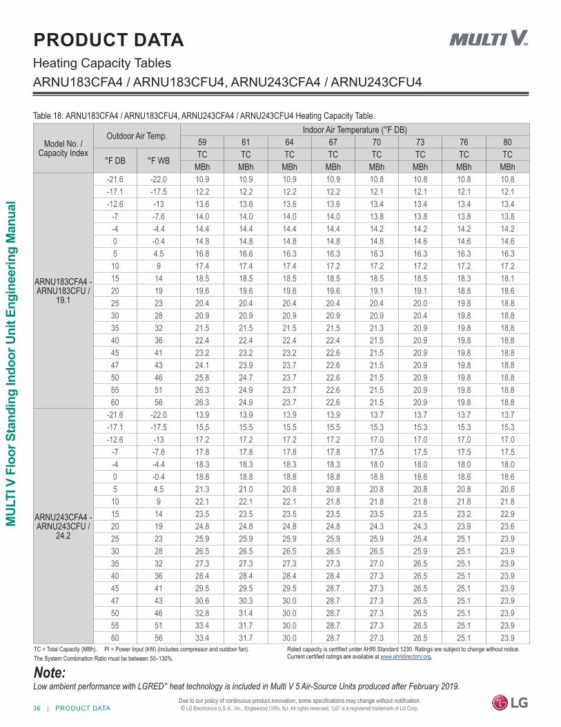
36 | PRODUCT DATA
MUL
TI V
Flo
or S
tand
ing
Indo
or U
nit E
ngin
eerin
g M
anua
l
Due to our policy of continuous product innovation, some specifications may change without notification. © LG Electronics U.S.A., Inc., Englewood Cliffs, NJ. All rights reserved. “LG” is a registered trademark of LG Corp.
Heating Capacity Tables
Table 18: ARNU183CFA4 / ARNU183CFU4, ARNU243CFA4 / ARNU243CFU4 Heating Capacity Table.
ARNU183CFA4 / ARNU183CFU4, ARNU243CFA4 / ARNU243CFU4
PRODUCT DATA
Model No. / Capacity Index
Outdoor Air Temp. Indoor Air Temperature (°F DB)59 61 64 67 70 73 76 80
°F DB °F WB TC TC TC TC TC TC TC TCMBh MBh MBh MBh MBh MBh MBh MBh
ARNU183CFA4 - ARNU183CFU /
19.1
-21.6 -22.0 10.9 10.9 10.9 10.9 10.8 10.8 10.8 10.8-17.1 -17.5 12.2 12.2 12.2 12.2 12.1 12.1 12.1 12.1-12.6 -13 13.6 13.6 13.6 13.6 13.4 13.4 13.4 13.4
-7 -7.6 14.0 14.0 14.0 14.0 13.8 13.8 13.8 13.8-4 -4.4 14.4 14.4 14.4 14.4 14.2 14.2 14.2 14.20 -0.4 14.8 14.8 14.8 14.8 14.8 14.6 14.6 14.65 4.5 16.8 16.6 16.3 16.3 16.3 16.3 16.3 16.3
10 9 17.4 17.4 17.4 17.2 17.2 17.2 17.2 17.215 14 18.5 18.5 18.5 18.5 18.5 18.5 18.3 18.120 19 19.6 19.6 19.6 19.6 19.1 19.1 18.8 18.625 23 20.4 20.4 20.4 20.4 20.4 20.0 19.8 18.830 28 20.9 20.9 20.9 20.9 20.9 20.4 19.8 18.835 32 21.5 21.5 21.5 21.5 21.3 20.9 19.8 18.840 36 22.4 22.4 22.4 22.4 21.5 20.9 19.8 18.845 41 23.2 23.2 23.2 22.6 21.5 20.9 19.8 18.847 43 24.1 23.9 23.7 22.6 21.5 20.9 19.8 18.850 46 25.8 24.7 23.7 22.6 21.5 20.9 19.8 18.855 51 26.3 24.9 23.7 22.6 21.5 20.9 19.8 18.860 56 26.3 24.9 23.7 22.6 21.5 20.9 19.8 18.8
ARNU243CFA4 - ARNU243CFU /
24.2
-21.6 -22.0 13.9 13.9 13.9 13.9 13.7 13.7 13.7 13.7-17.1 -17.5 15.5 15.5 15.5 15.5 15.3 15.3 15.3 15.3-12.6 -13 17.2 17.2 17.2 17.2 17.0 17.0 17.0 17.0
-7 -7.6 17.8 17.8 17.8 17.8 17.5 17.5 17.5 17.5-4 -4.4 18.3 18.3 18.3 18.3 18.0 18.0 18.0 18.00 -0.4 18.8 18.8 18.8 18.8 18.8 18.6 18.6 18.65 4.5 21.3 21.0 20.8 20.8 20.8 20.8 20.8 20.8
10 9 22.1 22.1 22.1 21.8 21.8 21.8 21.8 21.815 14 23.5 23.5 23.5 23.5 23.5 23.5 23.2 22.920 19 24.8 24.8 24.8 24.8 24.3 24.3 23.9 23.625 23 25.9 25.9 25.9 25.9 25.9 25.4 25.1 23.930 28 26.5 26.5 26.5 26.5 26.5 25.9 25.1 23.935 32 27.3 27.3 27.3 27.3 27.0 26.5 25.1 23.940 36 28.4 28.4 28.4 28.4 27.3 26.5 25.1 23.945 41 29.5 29.5 29.5 28.7 27.3 26.5 25.1 23.947 43 30.6 30.3 30.0 28.7 27.3 26.5 25.1 23.950 46 32.8 31.4 30.0 28.7 27.3 26.5 25.1 23.955 51 33.4 31.7 30.0 28.7 27.3 26.5 25.1 23.960 56 33.4 31.7 30.0 28.7 27.3 26.5 25.1 23.9
Low ambient performance with LGRED° heat technology is included in Multi V 5 Air-Source Units produced after February 2019.
TC = Total Capacity (MBh). PI = Power Input (kW) (includes compressor and outdoor fan).The System Combination Ratio must be between 50–130%.
Rated capacity is certified under AHRI Standard 1230. Ratings are subject to change without notice. Current certified ratings are available at www.ahridirectory.org.
APPLICATIONGUIDELINES
Selecting the Best Location on page 38General Mounting on page 39General Drain Piping Information on page 39Wiring Guidelines on page 41Wired Remote Controller Location on page 42Acronyms on page 43
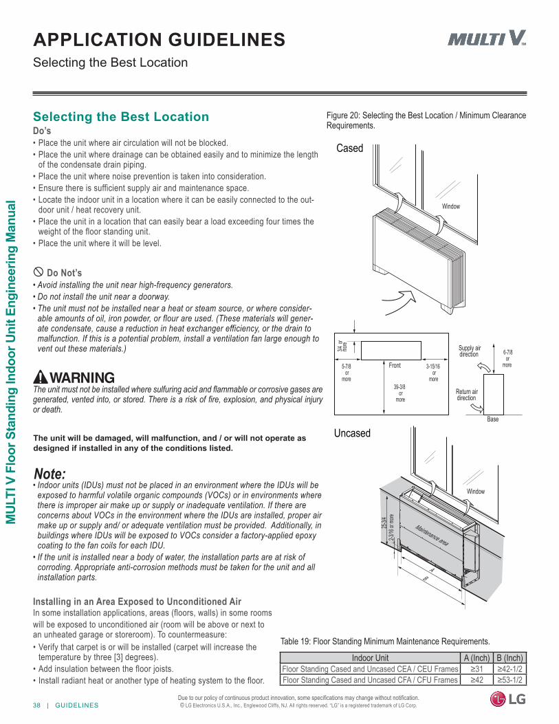
38 | GUIDELINES
MUL
TI V
Flo
or S
tand
ing
Indo
or U
nit E
ngin
eerin
g M
anua
l
Due to our policy of continuous product innovation, some specifications may change without notification. © LG Electronics U.S.A., Inc., Englewood Cliffs, NJ. All rights reserved. “LG” is a registered trademark of LG Corp.
APPLICATION GUIDELINESSelecting the Best Location
Figure 20: Selecting the Best Location / Minimum Clearance Requirements.
Selecting the Best LocationDo’s• Place the unit where air circulation will not be blocked.• Place the unit where drainage can be obtained easily and to minimize the length
of the condensate drain piping.• Place the unit where noise prevention is taken into consideration.• Ensure there is sufficient supply air and maintenance space.• Locate the indoor unit in a location where it can be easily connected to the out-
door unit / heat recovery unit.• Place the unit in a location that can easily bear a load exceeding four times the
weight of the floor standing unit.• Place the unit where it will be level.
Do Not’s• Avoid installing the unit near high-frequency generators.• Do not install the unit near a doorway.• The unit must not be installed near a heat or steam source, or where consider-
able amounts of oil, iron powder, or flour are used. (These materials will gener-ate condensate, cause a reduction in heat exchanger efficiency, or the drain tomalfunction. If this is a potential problem, install a ventilation fan large enough tovent out these materials.) 3/4
ormo
re
5-7/8or
more
3-15/16or
more
6-7/8or
moreFront
Base
Supply airdirection
Return airdirection
39-3/8 or
more
Window
B
Maintenance area
Window
A
25-3/4
2-3/16
or mo
re
Cased
Uncased
Table 19: Floor Standing Minimum Maintenance Requirements.
Indoor Unit A (Inch) B (Inch)Floor Standing Cased and Uncased CEA / CEU Frames ≥31 ≥42-1/2Floor Standing Cased and Uncased CFA / CFU Frames ≥42 ≥53-1/2
The unit must not be installed where sulfuring acid and flammable or corrosive gases are generated, vented into, or stored. There is a risk of fire, explosion, and physical injury or death.
The unit will be damaged, will malfunction, and / or will not operate as designed if installed in any of the conditions listed.
• Indoor units (IDUs) must not be placed in an environment where the IDUs will beexposed to harmful volatile organic compounds (VOCs) or in environments wherethere is improper air make up or supply or inadequate ventilation. If there areconcerns about VOCs in the environment where the IDUs are installed, proper airmake up or supply and/ or adequate ventilation must be provided. Additionally, inbuildings where IDUs will be exposed to VOCs consider a factory-applied epoxycoating to the fan coils for each IDU.
• If the unit is installed near a body of water, the installation parts are at risk ofcorroding. Appropriate anti-corrosion methods must be taken for the unit and allinstallation parts.
Installing in an Area Exposed to Unconditioned AirIn some installation applications, areas (floors, walls) in some roomswill be exposed to unconditioned air (room will be above or next toan unheated garage or storeroom). To countermeasure:• Verify that carpet is or will be installed (carpet will increase the
temperature by three [3] degrees).• Add insulation between the floor joists.• Install radiant heat or another type of heating system to the floor.
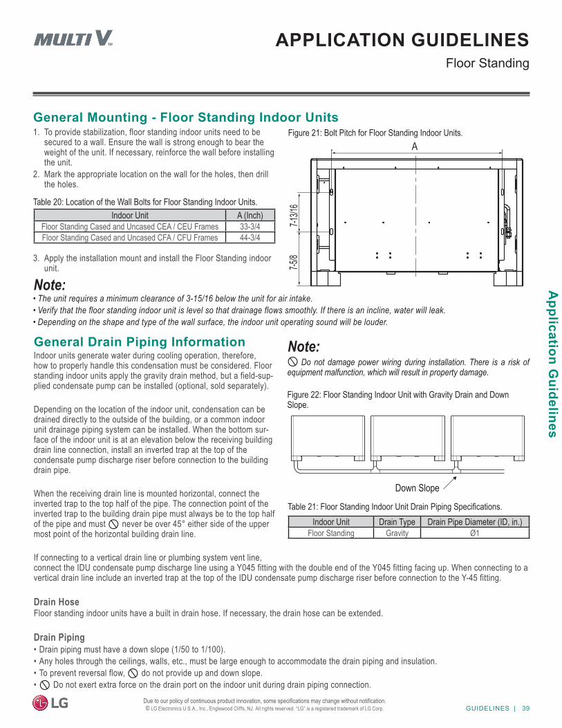
GUIDELINES | 39
Application G
uidelines
Due to our policy of continuous product innovation, some specifications may change without notification. © LG Electronics U.S.A., Inc., Englewood Cliffs, NJ. All rights reserved. “LG” is a registered trademark of LG Corp.
APPLICATION GUIDELINESFloor Standing
General Mounting - Floor Standing Indoor UnitsFigure 21: Bolt Pitch for Floor Standing Indoor Units.
• The unit requires a minimum clearance of 3-15/16 below the unit for air intake.• Verify that the floor standing indoor unit is level so that drainage flows smoothly. If there is an incline, water will leak.• Depending on the shape and type of the wall surface, the indoor unit operating sound will be louder.
7-13/1
6
A
7-5/8
Unit: Inch
Table 20: Location of the Wall Bolts for Floor Standing Indoor Units.Indoor Unit A (Inch)
Floor Standing Cased and Uncased CEA / CEU Frames 33-3/4Floor Standing Cased and Uncased CFA / CFU Frames 44-3/4
1. To provide stabilization, floor standing indoor units need to be secured to a wall. Ensure the wall is strong enough to bear the weight of the unit. If necessary, reinforce the wall before installing the unit.
2. Mark the appropriate location on the wall for the holes, then drill the holes.
3. Apply the installation mount and install the Floor Standing indoor unit.
General Drain Piping InformationIndoor units generate water during cooling operation, therefore, how to properly handle this condensation must be considered. Floor standing indoor units apply the gravity drain method, but a field-sup-plied condensate pump can be installed (optional, sold separately).
Depending on the location of the indoor unit, condensation can be drained directly to the outside of the building, or a common indoor unit drainage piping system can be installed. When the bottom sur-face of the indoor unit is at an elevation below the receiving building drain line connection, install an inverted trap at the top of the condensate pump discharge riser before connection to the building drain pipe.
When the receiving drain line is mounted horizontal, connect the inverted trap to the top half of the pipe. The connection point of the inverted trap to the building drain pipe must always be to the top half of the pipe and must never be over 45° either side of the upper most point of the horizontal building drain line.
If connecting to a vertical drain line or plumbing system vent line, connect the IDU condensate pump discharge line using a Y045 fitting with the double end of the Y045 fitting facing up. When connecting to a vertical drain line include an inverted trap at the top of the IDU condensate pump discharge riser before connection to the Y-45 fitting.
Drain HoseFloor standing indoor units have a built in drain hose. If necessary, the drain hose can be extended.
Drain Piping• Drain piping must have a down slope (1/50 to 1/100).• Any holes through the ceilings, walls, etc., must be large enough to accommodate the drain piping and insulation.• To prevent reversal flow, do not provide up and down slope.• Do not exert extra force on the drain port on the indoor unit during drain piping connection.
Do not damage power wiring during installation. There is a risk of equipment malfunction, which will result in property damage.
Figure 22: Floor Standing Indoor Unit with Gravity Drain and Down Slope.
Down Slope
Table 21: Floor Standing Indoor Unit Drain Piping Specifications.Indoor Unit Drain Type Drain Pipe Diameter (ID, in.)
Floor Standing Gravity Ø1
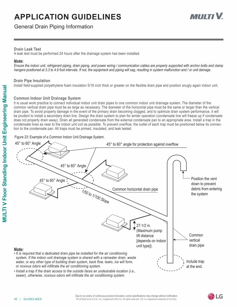
40 | GUIDELINES
MUL
TI V
Flo
or S
tand
ing
Indo
or U
nit E
ngin
eerin
g M
anua
l
Due to our policy of continuous product innovation, some specifications may change without notification. © LG Electronics U.S.A., Inc., Englewood Cliffs, NJ. All rights reserved. “LG” is a registered trademark of LG Corp.
General Drain Piping InformationAPPLICATION GUIDELINES
Drain Leak TestA leak test must be performed 24 hours after the drainage system has been installed.
Figure 23: Example of a Common Indoor Unit Drainage System.
Common Indoor Unit Drainage SystemIt is usual work practice to connect individual indoor unit drain pipes to one common indoor unit drainage system. The diameter of the common vertical drain pipe must be as large as necessary. The diameter of the horizontal pipe must be the same or larger than the vertical drain pipe. To avoid property damage in the event of the primary drain becoming clogged, and to optimize drain system performance, it will be prudent to install a secondary drain line. Design the drain system to plan for winter operation (condensate line will freeze up if condensate does not properly drain away). Drain all generated condensate from the external condensate pan to an appropriate area. Install a trap in the condensate lines as near to the indoor unit coil as possible. To prevent overflow, the outlet of each trap must be positioned below its connec-tion to the condensate pan. All traps must be primed, insulated, and leak tested.
Common horizontal drain pipe 1/50 to 1/100 Slope
27-1/2 in. (Maximum pumplift distance [depends on indoorunit type]).
Include trapat the end.
45° to 60° Angle
Position the vent down to preventdebris from enteringthe system
45° to 60° Angle
45° to 60° Angle
45° to 60° angle for protection against overflow
Common verticaldrain pipe
• It is required that a dedicated drain pipe be installed for the air conditioning system. If the indoor unit drainage system is shared with a rainwater drain, waste water, or any other type of building drain system, back flow, leaks, ice will form, or noxious odors will infiltrate the air conditioning system.
• Install a trap if the drain access to the outside faces an undesirable location (i.e., sewer), otherwise, noxious odors will infiltrate the air conditioning system.
Ensure the indoor unit, refrigerant piping, drain piping, and power wiring / communication cables are properly supported with anchor bolts and clamp hangers positioned at 3.3 to 4.9 foot intervals. If not, the equipment and piping will sag, resulting in system malfunction and / or unit damage.
Drain Pipe InsulationInstall field-supplied polyethylene foam insulation 5/16 inch thick or greater on the flexible drain pipe and position snugly again indoor unit.
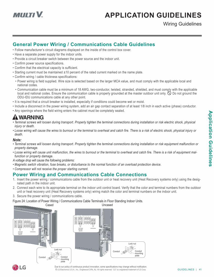
GUIDELINES | 41
Application G
uidelines
Due to our policy of continuous product innovation, some specifications may change without notification. © LG Electronics U.S.A., Inc., Englewood Cliffs, NJ. All rights reserved. “LG” is a registered trademark of LG Corp.
Wiring GuidelinesAPPLICATION GUIDELINES
General Power Wiring / Communications Cable Guidelines• Follow manufacturer’s circuit diagrams displayed on the inside of the control box cover.• Have a separate power supply for the indoor units.• Provide a circuit breaker switch between the power source and the indoor unit.• Confirm power source specifications.• Confirm that the electrical capacity is sufficient.• Starting current must be maintained ±10 percent of the rated current marked on the name plate.• Confirm wiring / cable thickness specifications:
• Power wiring is field supplied. Wire size is selected based on the larger MCA value, and must comply with the applicable local and national codes.
• Communication cable must be a minimum of 18 AWG, two-conductor, twisted, stranded, shielded, and must comply with the applicable local and national codes. Ensure the communication cable is properly grounded at the master outdoor unit only. Do not ground the ODU-IDU communications cable at any other point.
• It is required that a circuit breaker is installed, especially if conditions could become wet or moist.• Include a disconnect in the power wiring system, add an air gap contact separation of at least 1/8 inch in each active (phase) conductor.• Any openings where the field wiring enters the cabinet must be completely sealed.
• Terminal screws will loosen during transport. Properly tighten the terminal connections during installation or risk equipment malfunction or property damage.
• Loose wiring will cause unit malfunction, the wires to burnout or the terminal to overheat and catch fire. There is a risk of equipment mal-function or property damage.
A voltage drop will cause the following problems:• Magnetic switch vibration, fuse breaks, or disturbance to the normal function of an overload protection device.• Compressor will not receive the proper starting current.
• Terminal screws will loosen during transport. Properly tighten the terminal connections during installation or risk electric shock, physical injury or death.
• Loose wiring will cause the wires to burnout or the terminal to overheat and catch fire. There is a risk of electric shock, physical injury or death.
Power Wiring and Communications Cable Connections1. Insert the power wiring / communications cable from the outdoor unit or heat recovery unit (Heat Recovery systems only) using the desig-
nated path in the indoor unit.2. Connect each wire to its appropriate terminal on the indoor unit control board. Verify that the color and terminal numbers from the outdoor
unit or heat recovery unit (Heat Recovery systems only) wiring match the color and terminal numbers on the indoor unit.3. Secure the power wiring / communications cable.Figure 24: Location of Power Wiring / Communications Cable Terminals in Floor Standing Indoor Units.
Lock nut
Conduitmountingplate
Conduit
Lock nut
Conduitmountingplate
Conduit
UncasedCased
Power SupplyHigh Voltage(208/230V)
Communications
A BL(L1) N(L2) YL RD BK
Power SupplyHigh Voltage(208/230V)
Communications
A BL(L1) N(L2) YL RD BK
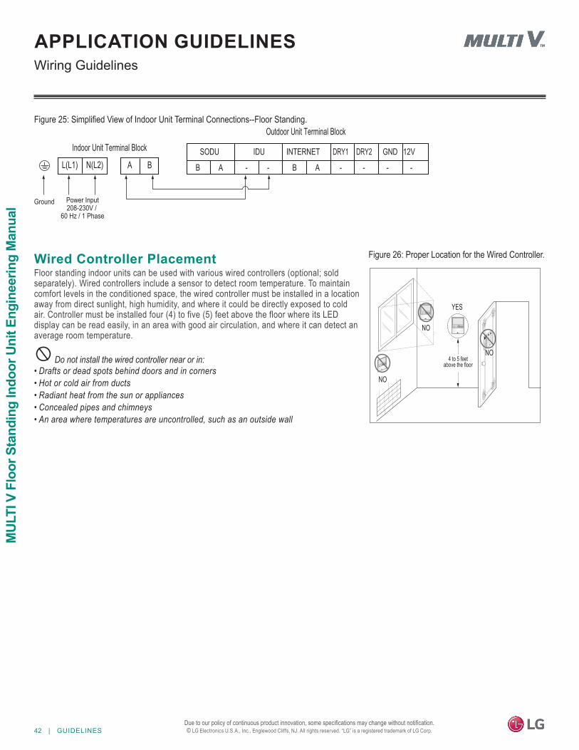
42 | GUIDELINES
MUL
TI V
Flo
or S
tand
ing
Indo
or U
nit E
ngin
eerin
g M
anua
l
Due to our policy of continuous product innovation, some specifications may change without notification. © LG Electronics U.S.A., Inc., Englewood Cliffs, NJ. All rights reserved. “LG” is a registered trademark of LG Corp.
A - - - - - -AB B
GND 12VDRY2DRY1INTERNETIDUSODUIndoor Unit Terminal Block
A B
Outdoor Unit Terminal Block
Power Input208-230V /
60 Hz / 1 Phase
Ground
L(L1) N(L2)
Wiring GuidelinesAPPLICATION GUIDELINES
Figure 25: Simplified View of Indoor Unit Terminal Connections--Floor Standing.
Wired Controller PlacementFloor standing indoor units can be used with various wired controllers (optional; sold separately). Wired controllers include a sensor to detect room temperature. To maintain comfort levels in the conditioned space, the wired controller must be installed in a location away from direct sunlight, high humidity, and where it could be directly exposed to cold air. Controller must be installed four (4) to five (5) feet above the floor where its LED display can be read easily, in an area with good air circulation, and where it can detect an average room temperature.
Do not install the wired controller near or in:• Drafts or dead spots behind doors and in corners• Hot or cold air from ducts• Radiant heat from the sun or appliances• Concealed pipes and chimneys• An area where temperatures are uncontrolled, such as an outside wall
Figure 26: Proper Location for the Wired Controller.
4 to 5 feetabove the floor
NO
NO
NO
YES
Remote Controlle r
TEMP
Remote Controlle r
TEMP
Rem ot e Cont roller
TEMP
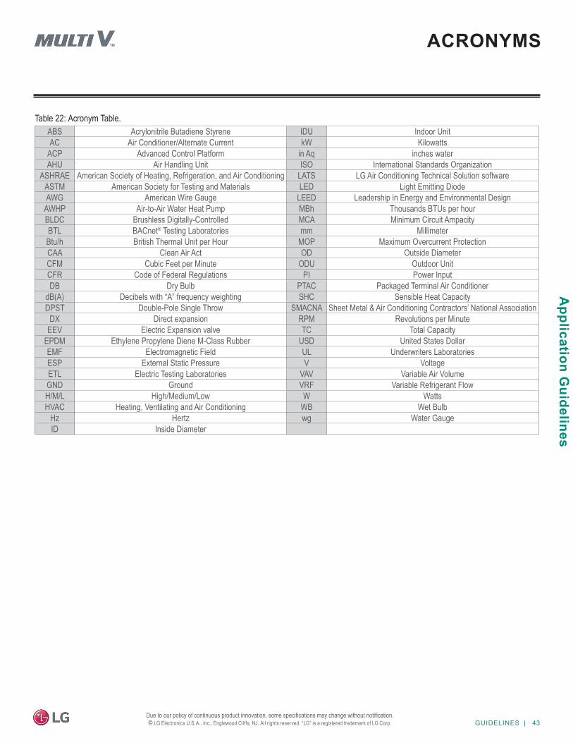
GUIDELINES | 43
Application G
uidelines
Due to our policy of continuous product innovation, some specifications may change without notification. © LG Electronics U.S.A., Inc., Englewood Cliffs, NJ. All rights reserved. “LG” is a registered trademark of LG Corp.
ACRONYMS
ABS Acrylonitrile Butadiene Styrene IDU Indoor UnitAC Air Conditioner/Alternate Current kW Kilowatts
ACP Advanced Control Platform in Aq inches waterAHU Air Handling Unit ISO International Standards Organization
ASHRAE American Society of Heating, Refrigeration, and Air Conditioning LATS LG Air Conditioning Technical Solution softwareASTM American Society for Testing and Materials LED Light Emitting DiodeAWG American Wire Gauge LEED Leadership in Energy and Environmental Design
AWHP Air-to-Air Water Heat Pump MBh Thousands BTUs per hourBLDC Brushless Digitally-Controlled MCA Minimum Circuit AmpacityBTL BACnet® Testing Laboratories mm MillimeterBtu/h British Thermal Unit per Hour MOP Maximum Overcurrent ProtectionCAA Clean Air Act OD Outside DiameterCFM Cubic Feet per Minute ODU Outdoor UnitCFR Code of Federal Regulations PI Power InputDB Dry Bulb PTAC Packaged Terminal Air Conditioner
dB(A) Decibels with “A” frequency weighting SHC Sensible Heat CapacityDPST Double-Pole Single Throw SMACNA Sheet Metal & Air Conditioning Contractors’ National Association
DX Direct expansion RPM Revolutions per MinuteEEV Electric Expansion valve TC Total Capacity
EPDM Ethylene Propylene Diene M-Class Rubber USD United States DollarEMF Electromagnetic Field UL Underwriters LaboratoriesESP External Static Pressure V VoltageETL Electric Testing Laboratories VAV Variable Air VolumeGND Ground VRF Variable Refrigerant FlowH/M/L High/Medium/Low W WattsHVAC Heating, Ventilating and Air Conditioning WB Wet Bulb
Hz Hertz wg Water GaugeID Inside Diameter
Table 22: Acronym Table.
EM_MultiV_FloorStanding_IndoorUnits_10_20Supersedes: EM_MultiV_FloorStanding_IndoorUnits_11_19
EM_MultiV_FloorSuspendCovert_IndoorUnits_8_17
LG Electronics, U.S.A., Inc.Air Conditioning Technologies4300 North Point ParkwayAlpharetta, Georgia 30022www.lghvac.com