features - jegs.com
TRANSCRIPT

1
• Tachometer Gauge 2 1/16” INCH • Wiring Harness• Mounting Cup (Not required for pod installation)• (2) Neoprene EDPM Grommets
PACKAGE CONTAINS:
FEATURES:SPEK PERFORMANCE GAUGE TACHOMETER FEATURES:
• INTELLIGENT ELECTRICAL GAUGES.
• GAUGES ARE PROGRAMMED THROUGH COMMAND KEYS ON FACEPLATE.
• STEPPER MOTOR DRIVES THE GAUGE POINTER OVER A 280 DEGREE SWEEP.
• WIDE-ANGLE-DIAL™ HAS A 15% LARGER VIEWING AREA ON A 2 1/16” GAUGE.
• PROGRAMMABLE 7 COLOR DIAL AND RED POINTER ILLUMINATION.
• OPTIONAL OUTPUT CONTROL MODULE.
INSTALLATION INSTRUCTIONS:1 DISCONNECT NEGATIVE (-) BATTERY TERMINAL.
2 VARIOUS MOUNTING SOLUTIONS ARE PRESENTED BY PROPARTS, LLC ON THEIR WEBSITE AT www.SPEKPRO.comDASH INSTALLATION: SELECT LOCATION IN THE DASH TO MOUNT GAUGE AND CUT A 2 1/16” HOLE. USE A FILE TO INCREASE THE HOLE SIZE IF REQUIRED. BE SURE THERE IS SUFFICIENT ROOM BEHIND THE HOLE FOR THE METER CASE AND THE CONNECTORS YOU WILL USE.
3 IF A SUITABLE HOLE IN THE FIRE WALL IS NOT AVAILABLE, CUT AN 11/16” HOLE.
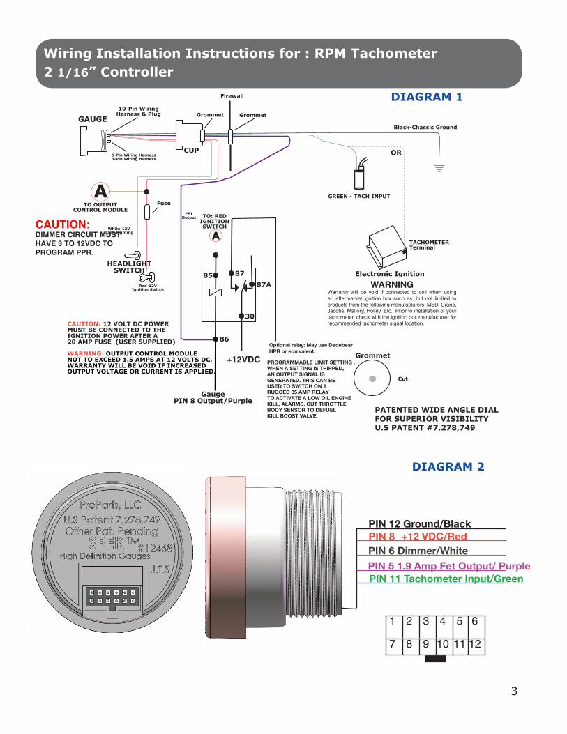
4 TWO GROMMETS MUST BE CUT TO PERMIT INSTALLATION OF WIRING HARNESS. (SEE DIAGRAM 1)
5 INSTALL INSTALL THE GROMMET AND MOUNTING CUP ON THE WIRING HARNESS AS SHOWN IN DIAGRAM 1. GROMMET IS FOR THE HOLE IN THE FIREWALL.
SPEK™ MONITOR AND CONTROL PERFORMANCE GAUGE TACHOMETER
Wiring Installation Instructions for : RPM Tachometer 2 1/16” Controller
FOR SERVICE SEND TO: SPEK-PRO SERVICE • 413 West Elm Street • Sycamore, Illinois 60178 USA www.spekpro.com • [email protected] • (866) 248-6357
2650-1670 -00 7/22/13

6 DO NOT CONNECT WIRING HARNESS TO THE GAUGE UNTIL THE OTHER CONNECTIONS HAVE BEEN MADE AND TESTED.
7 CONNECT THE RED (+ 12 VOLT SUPPLY) WIRE TO “ON” CIRCUITS THAT GET POWER WHEN THE IGNITION IS TURNED-ON. THIS CIRCUIT MUST BE FUSED BEFORE THE iGNITION SWITCH (1 AMP, 3AG FAST ACTING).
8 CONNECT THE BLACK WIRE TO A GOOD GROUNDING POINT ON THE CAR’S CHASSIS.
9 CONNECT THE WHITE WIRE TO THE DIMMER VOLTAGE GOING TO THE DASH LIGHTS. THIS WILL CAUSE THE METER BRIGHTNESS TO TRACK THE BRIGHTNESS OF THE REST OF THE INDICATORS.THIS CIRCUIT MUST PRODUCE 3 TO 12VDC BEFORE THE PPR CAN BE PROGRAMMED.
10 CONNECT THE SENSING WIRE TO THE PRIMARY TERMINAL ON THE IGNITION COIL (STANDARD-TYPE COIL) OR TO THE AUXILIARY TERMINAL MEANT FOR THE TACH WIRE (AFTER MARKET, HIGH PERFORMANCE COIL). DO NOT CONNECT TO COIL ON MSD IGNITION. ATTACH ONLY TO TACH TERMINAL.
11 PLUG THE WIRING HARNESSES INTO THE GAUGE AND MOUNT IN POD OR DASH.
12 FOR DASH INSTALLATION, ATTACH MOUNTING CUP OVER THE BACK OF THE GAUGE AND HAND TIGHTEN. DO NOT OVER TIGHTEN. MOUNT CUP BEFORE INSTALLING GROMMET. FAILURE TO DO SO WILL TWIST WIRES CAUSING A SHORT CIRCUIT.
13 POWER UP THE GAUGE AND INSPECT ALL CONNECTIONS. IF GAUGE IS OPERATING NORMALLY, PROCEED TO “PROGRAMMING MANUAL”.
2
Wiring Installation Instructions for : RPM Tachometer 2 1/16” Controller
����������������������� � ���������
��������������������������������������������� ���
��������� ������������������
GREEN - TACH INPUT
TACHOMETERTerminal
Electronic Ignition
.
Black-Chassis Ground
Firewall
Grommet10-Pin Wiring
Harness & PlugGAUGE
5-Pin Wiring Harness3-Pin Wiring Harness
ORCUP
Grommet
Red-12VIgnition Switch
White-12VDash Lighting
HEADLIGHTSWITCH
Fuse
Grommet
Cut
85
86
87A
30
87
GaugePIN 8 Output/Purple
FETOutput
CAUTION: 12 VOLT DC POWERMUST BE CONNECTED TO THEIGNITION POWER AFTER A20 AMP FUSE (USER SUPPLIED)
WARNING: OUTPUT CONTROL MODULENOT TO EXCEED 1.5 AMPS AT 12 VOLTS DC.WARRANTY WILL BE VOID IF INCREASEDOUTPUT VOLTAGE OR CURRENT IS APPLIED.
Optional relay: May use DedebearHPR or equivalent.
PROGRAMMABLE LIMIT SETTING .WHEN A SETTING IS TRIPPED,AN OUTPUT SIGNAL ISGENERATED. THIS CAN BEUSED TO SWITCH ON ARUGGED 35 AMP RELAYTO ACTIVATE A LOW OIL ENGINEKILL, ALARMS, CUT THROTTLEBODY SENSOR TO DEFUELKILL BOOST VALVE.
ATO OUTPUT
CONTROL MODULE
A
TO: REDIGNITIONSWITCH
+12VDC
WARNINGWarranty will be void if connected to coil when using an aftermarket ignition box such as, but not limited to products from the following manufacturers: MSD, Crane, Jacobs, Mallory, Holley, Etc.. Prior to installation of your tachometer, check with the ignition box manufacturer for recommended tachometer signal location.
DIAGRAM 1
PATENTED WIDE ANGLE DIAL FOR SUPERIOR VISIBILITY U.S PATENT #7,278,749
3
Wiring Installation Instructions for : RPM Tachometer 2 1/16” Controller
DIAGRAM 2
CAUTION:DIMMER CIRCUIT MUST HAVE 3 TO 12VDC TO PROGRAM PPR.
1
2 3 4 5 6
7 8 9 10 11 12

Wiring Installation Instructions for : RPM Tachometer 2 1/16” Controller
4
THERE ARE THREE SECTIONS TO THIS MANUAL: WIRING INSTRUCTIONS, PROGRAMMING INSTRUCTIONS AND FLOW CHART PROGRAMMING INSTRUCTIONS. PLEASE READ EACH SECTION CAREFULLY BEFORE ATTEMPTING TO INSTALL OR OPERATE THIS PRODUCT.
WARNING:
• ALL INSTRUCTIONS IN THIS MANUAL MUST BE FOLLOWED TO INSURE SAFE INSTALLATION AND OPERATION OF THIS PRODUCT.• NEVER DISASSEMBLE MODIFY OR TAMPER WITH THIS PRODUCT. THIS COULD CAUSE DAMAGE AND MAKE THEM UNSAFE TO USE. TAMPERING WITH THE PRODUCT WILL VOID THE LIMITED WARRANTY.• INSTALLATION MUST BE PERFORMED BY AN EXPERIENCED AUTOMOTIVE TECHNICIAN.• INSTALLER MUST USE SAFETY GLASSES.• DISCONNECT THE NEGATIVE BATTERY TERMINAL BEFORE BEGINNING INSTALLATION. PROPARTS LLC IS NOT RESPONSIBLE FOR DAMAGE TO ENGINE, VEHICLE OR UNIT CAUSED BY ELECTRICAL SHORTS.• DURING INSTALLATION, DO NOT INTERFERE WITH ANY EXISTING CONNECTIONS OR WIRES.• ALL ELECTRICAL CONNECTIONS USE SOLDER LESS CONNECTORS AND INSULATE ALL CONNECTIONS WITH ELECTRICAL TAPE. • AVOID WIRING NEAR ENGINE, EXHAUST SYSTEM, TURBINE OR ANY AREA THAT MAY RESULT IN DAMAGE. • DISCONTINUE USE OF THE PRODUCT IF SMOKE OR A STRANGE ODOR IN PRESENT.
CAUTION
• PROPARTS LLC IS NOT RESPONSIBLE FOR INCORRECT INSTALLATION OR PROGRAMMING OF SPEK™ GAUGES OR CONTROLLERS.• SPEK™ GAUGES AND CONTROLLERS ARE DESIGNED FOR 12V DC ELECTRICAL SYSTEMS WITH A NEGATIVE GROUND. • DO NOT ADJUST THE GAUGES OR GAUGE PROGRAM WHILE DRIVING• OBEY ALL RULES AND REGULATIONS OF HIGHWAY AND STREET DRIVING.• INSTALL SENSOR AND WIRE AWAY FROM HIGH HEAT AND / OR VIBRATION AREAS.• USE CARE WHEN CONNECTING OR DISCONNECTING THE WIRING HARNESS. PULL OUT EACH CONNECTOR WHILE PRESSING THE LOCK OF THE CONNECTOR FIRMLY.• IF THE BATTERY TERMINAL IS DISCONNECTED, THE AUDIO, CLOCK AND OTHER MEMORY DATA MAY BE LOST. THE NECESSARY DATA WILL HAVE TO BE RESET AFTER INSTALLATION.

Programming Instructions for : RPM Tachometer 2 1/16” Controller
5
DOWN MODE UP+–
MAIN MENU
NORMAL OPERATION
PEAK PLAYBACK
HIGH RED-LINE SETTING
LOW THRESHOLD SETTING
COLOR SCHEME
DIAL BRIGHTNESS
SUBMENU
OPTION:SELECT PPR
OPTION:RESTORE FACTORY DEFAULT
OPTION: DEMO MODE
OPTION: POINTER BRIGHTNESS
U. S. PATENTS 7,612,660 AND 7,278,749 ADDITIONAL PATENTS PENDING.
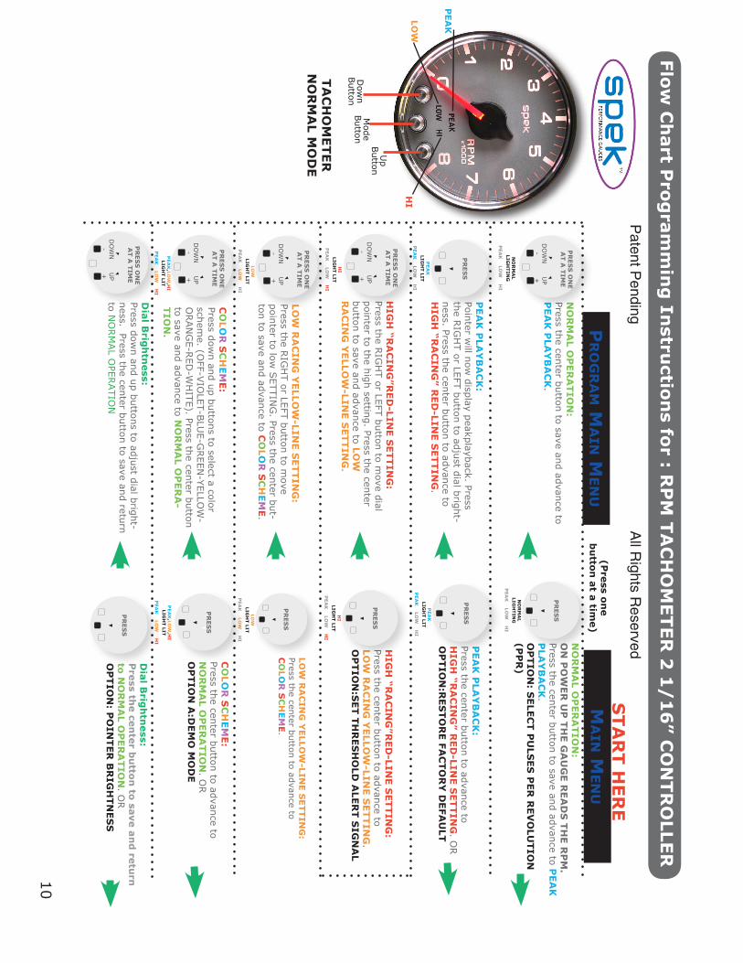
Refer to the “Flow Chart Programming Instructions” while reviewing this guide.Gauge is field programmable by the operator while installed in the vehicle. This programming isaccessed by pressing the control buttons located on the face or the meter dial, ONE AT A TIME.The “Down” and “Up” buttons move the pointer to a desired setting or controls the faceplateillumination. The center “Mode” button will save the setting you choose and proceed to the nextlevel. Pressing the “Mode” and “Up” or “Mode” and “Down” buttons simultaneously and holdingthem for 5 seconds in any level will shift you to the Submenu.
SPEK™ MONITOR AND CONTROL PERFORMANCE GAUGE TACHOMETER

PROGRAMMING STARTS IN
MAIN MENUPRESS PROGRAM BUTTON ONE (1) AT A TIME IN THE MAIN MENU MODE.
1 NORMAL OPERATION: On power up, the meter usually starts in NORMAL operating mode. The Tachometer will read en-gine’s RPM. Press the center “mode” button to advance to 2 PEAK PLAYBACK
2 PEAK PLAYBACK: Reads the highest value displayed on the meter since the last time the “Peak” value was displayed. Pressing the “Down” or “Up” control button will control the gauge dial illumination. Press the center “Mode” button to advance to 3 HIGH RACING RED-LINE SETTING
3 HIGH RACING RED-LINE SETTING: Sets the point at which “HIGH” warning RED-LINE is reached for that specific gauge. The “Down and “Up” buttons will move the dial pointer to select “Maximum RED-LINE”. During normal operation the gauge constantly monitors the sensor value and compares it to the “HIGH” RED-LINE. If the threshold is exceeded, the red “HI” indicator is turned on and an output signal generated. Press the center “Mode” button to save the setting and advance to 4 LOW RACING YELLOW-LINE SETTING
4 LOW RACING YELLOW-LINE SETTING: Set the Minimum RED-LINE: Sets the point at which “LOW” warning threshold is reached for that specific gauge. The “Down” and “Up” buttons will move the dial pointer to select the LOW RACING YELLOW-LINE SETTING. During normal operation the gauge constantly monitors the sensor value and compares it to the “LOW” threshold. If the sensor value drops below the threshold, the yellow “LOW” indicator is turned on and an output signal generated. Press the center “Mode” button save the setting and advance to 5 COLOR SCHEME
5 COLOR SCHEME: Set Faceplate Color Scheme: Operator can select the color of the gauge dial illumination. Each time you press the “Down” control button you scroll through dial color selection until the dial light goes off. Then press the “Up” button to reverse the scroll. Select your dial color illumination by pressing the center “Mode” button to save the setting and advance to NORMAL OPERATION.
6 DIAL BRIGHTNESS: Adjust the dial brightness for day or evening driving conditions The RIGHT and LEFT command but-tons will dim or brighten the faceplate illumination. Press the center “Mode” button to save the set-
ting and advance you to NORMAL OPERATION
Programming Instructions for : RPM Tachometer 2 1/16” Controller
6

SUBMENUSUBMENU IS ACCESSED THROUGH THE MAIN MENU. FIRST GO TO THE APPROPRIATE LEVEL OF THE MAIN MENU AND THEN FOLLOW THE INSTRUCTIONS IN THE PROGRAMMING FLOW DIAGRAM TO ENTER THE SUBMENU. PRESS THE “MODE” AND “UP” OR “MODE” AND “DOWN” BUTTONS SIMULTANEOUSLY FOR 5 SECONDS TO ENTER THE SUBMENU AND ONE BUTTON AT A TIME WHILE IN THAT SUBMENU.
OPTION:SELECT PPR: (Pulses Per Revolution) Select the PPR value by pressing “Down or “Up” button to move dial pointer to corresponding RPM. For additional information see the Tachometer Sense Line Attachment and Meter Setting section on page 4. OPTION:RESTORE FACTORY DEFAULT: TO RESTORE FACTORY DEFAULTS, PRESS THE :MODE” BUTTON ONCE TO ENTER THE PEAK PLAYBACK. THEN PRESS AND HOLD THE “MODE” AND “UP” BUTTONS FOR FIVE SECONDS. Activation of the Default will erase all field calibration setup settings that are programmed. Factory calibrations will not be affected.
OPTION A:DEMO MODE: Displays the features of the meter. The pointer goes up and down the scale, the dial colors change and the HI, LOW and PEAK warning indicators light. The Demo mode does not time out. If the gauge is turned off in the Demo mode, it will start up in the Demo Mode. Press the “Mode” button to return the gauge to NORMAL operation.
OPTION: POINTER BRIGHTNESS MODE: The “Down” and “Up” buttons adjust the dial pointer brightness to blend in with original manufacturer’s gauges and the owner’s requirements Press the center MODE button to save the setting and return to NORMAL OPERATION
PROGRAMMING INFORMATION:• TO RESET THE PROGRAM TO NORMAL OPERATION FROM ANY MODE PRESS THE “UP” AND “DOWN” BUTTONS SIMULTANEOUSLY. THIS SOFT RESET CANCELS THE INFORMATION YOU PROGRAMMED IN THAT MODE ONLY AND RETURN YOU TO NORMAL OPERATION.
• THE FACEPLATE WILL “FLASH” WHEN BUTTONS ARE DEPRESSED TO ACKNOWLEDGE COMMANDS.
• PROGRAMMING ERRORS WILL BE SIGNALLED BY FLASHING THE FACEPLATE LIGHTING “PURPLE”, “BLUE”, “GREEN” THEN “ORANGE”.
• IF PROGRAMMING IS INACTIVE FOR 60 SECONDS THE MODE WILL TIME OUT AND THE GAUGE WILL RETURN TO NORMAL OPERATION, EXCEPT FOR THE DEMONSTRATION MODE. THE DEMO MODE WILL NOT TIME OUT UNTIL THE CENTER “MODE” BUTTON IS PRESSED IF THE GAUGE IS TURNED OFF IN THE DEMO MODE, IT WILL START UP IN THE DEMO MODE.
Programming Instructions for : RPM Tachometer 2 1/16” Controller
7

TACHOMETER SENSE LINE ATTACHMENTS AND METER SCALING
GASOLINE ENGINESThe WHITE/DIMMER circuit must be installed and supply 3 to 12vdc before the PPR can be progammed
Attach the sensing line to the primary side of a spark coil, and then set the calibration PPR value for your spark configuration, using directions for the CALIBRATION option.
Once upon a time, there was just one configuration: a spark coil, a distributor, and then wires from the distributor cap to the individual sparkplugs. If your car is like this, use the table below:
FOR “CLASSIC” ONE-IGNITION-COIL ENGINES
IF YOU HAVE ONE COIL PER PLUG CONNECT TO ANY SPARK COIL PRIMARY
IF YOU HAVE ONE COIL PER TWO PLUGS CONNECT TO ANY SPARK COIL PRIMARY
DIESEL ENGINESModern diesel engines usually have camshaft sensors or electronic injector pumps. If there is one injector per cylinder, the signal from the pump drive will be 1/2 PPR. Similarly, if there is a camshaft sensor signal the signal will be ½ PPR. Set the calibration at a reading of 500.
If there is no electronic cam sensing or fuel injection in your diesel engine, the procedure is more com-plex. A signal can be obtained from the alternator by attaching a wire directly to the winding of the sta-tor before it goes to one of the rectifier diodes. This signal will be proportional to engine speed, but the
Programming Instructions for : RPM Tachometer 2 1/16” Controller
8
# PLUG
24681012
PULSES PER REVOLUTION (PPR)
123456
METER SETTING
100020003000400050006000
# PLUG
Any
PULSES PER REVOLUTION (PPR)
1/2
METER SETTING
500
# PLUG
Any
PULSES PER REVOLUTION (PPR)
1
METER SETTING
1000

proportionality must be learned. See the TACH CALIBRATION procedure for details, using meter set-ting 0 to force learning.
SPECIAL SCALING FUNCTIONS
Several Proparts meters require a setup procedure to define the kind of input they are looking at. These are:Tachometer – the user needs to tell it the number of “pulses per revolution” (PPR) coming into its sense line. This number varies widely between makes and models of cars. The default value is an eight cylinder engine with 4 PPR. The program setting is 4000RPM.Speedometer – the user needs to tell it the number of pulses that come in, per mile of travel.O2 sensor – the user needs to tell it whether the sensor is narrowband (with a 0-1 volt output) or a wideband sensor with a 0...5 volt output Once the meter is hooked up, the procedures are relatively painless.
TO SET UP SCALING
Turn the ignition off and on again to assure that the meter is in a reset state.If it starts up with the face changing color and the pointer going up and down continuously, the meter is in demo mode. Press the center button before continuing.
TACH CALIBRATION First read the section on TACHOMETER SENSE LINE ATTACHMENTS AND METER SCALING in order to find out how you need to set the meter. When you have figured out what PPR setting you are to use, press the Mode and Up buttons simultaneously for five (5) seconds. The dial will flash blue rapidly. This places the meter in the scale-setting mode. Use the Down and Up buttons to move the meter pointer to the appropriate RPM reading according to the table. If you have selected an “RPM” reading of 1000 or up, just press the center button to leave the scale setting mode and resume normal operation with the selected scaling.
If you were forced to use the alternator as a signal source, you selected an RPM of “0.” Now you must tell the motor when it is operating at 2000 RPM. Using a strobe light, slowly increase the enginspeed till you hit 2000 RPM. The meter will read some nonzero value that increases and decreases with engine speed, but it will not be accurate. While the engine is running steadily at 2000 RPM, press the mode button. Your meter is calibrated. You can verify the setting by turning the ignition switch off and on again, starting the car, and checking whether the idle speed on your tachometer is the same as the speed you measure with a strobe light.
Programming Instructions for : RPM Tachometer 2 1/16” Controller
9
U.S. PATENT # 7,612,660U.S. PATENT # 7,278,749ADDITIONAL PATENTS PENDING
12 MONTH LIMITED WARRANTY
Spek-Pro/Auto Meter Products, Inc. warrants to the consumer that all Auto Meter High Performance products will be free from defects in material and workmanship for a period of twelve (12) months from date of the original purchase. Products that fail within this 12 month warranty period will be repaired or replaced at Auto Meter’s option to the consumer, when it is determined by Spek-Pro/Auto Meter Products, Inc. that the product failed due to defects in material or workmanship. This warranty is limited to the repair or replacement of parts in the Spek-Pro/Auto Meter Instruments. In no event shall this warranty exceed the original purchase price of the Auto Meter instruments nor shall Spek-Pro/Auto Meter Products, Inc. be responsible for special, incidental or consequential damages or costs incurred due to the failure of this product. Warranty claims to Spek-Pro/Auto Meter must be transportation prepaid and accompanied with dated proof of purchase. This warranty applies only to the original purchaser of product and is non-transferable. All implied warranties shall be limited in duration to the said 12 month warranty period. Breaking the instrument seal, improper use or installation, accident, water damage, abuse, unauthorized repairs or alterations voids this warranty. Spek-Pro/Auto Meter Products, Inc. disclaims any liability for consequential damages due to breach of any written or implied warranty on all products manufactured by Auto Meter.
PEA
K
LIGH
T LIT
PEA
K LO
W H
I
LOW
LIG
HT LIT
PEA
K LO
W H
I
PEA
K,LO
W,H
I LIG
HT LIT
PEA
K LO
W H
I
PEA
K,LO
W,H
I LIG
HT LIT
PEA
K LO
W H
I
LOW
LIG
HT LIT
PEA
K LO
W H
I
PEA
K
LIGH
T LIT
PEA
K LO
W H
I
LOW
RA
CIN
G Y
ELLO
W-LIN
E S
ETTIN
G:
Press the center button to advance to C
OLO
R S
CH
EM
E.
Pr
og
ra
m m
ain m
en
u
STA
RT H
ER
EM
ain M
en
u(P
ress o
ne
bu
tton
at a
time)
NO
RM
AL O
PER
ATIO
N:
Press the center button to save and advance to P
EA
K P
LAY
BA
CK
.
NO
RM
AL
LIGH
TIN
GP
EA
K LO
W H
I
PEA
K P
LAY
BA
CK
: Pointer w
ill now display peakplayback. Press
the RIG
HT or LEFT button to adjust dial bright-
ness. Press the center button to advance to H
IGH
“RA
CIN
G” R
ED
-LINE S
ETTIN
G.
HIG
H “R
AC
ING
”RED
-LINE S
ETTIN
G:
Press the RIG
HT or LEFT button to m
ove dial pointer to the high setting. Press the center button to save and advance to LO
W
RA
CIN
G Y
ELLO
W-LIN
E S
ETTIN
G.
HI
LIGH
T LIT
PEA
K LO
W H
I
LOW
RA
CIN
G Y
ELLO
W-LIN
E S
ETTIN
G:
Press the RIG
HT or LEFT button to m
ove pointer to low
SETTIN
G. Press the center but-
ton to save and advance to CO
LOR
SC
HEM
E.
CO
LOR
SC
HEM
E:
Press down and up buttons to select a color
scheme. (O
FF-VIO
LET-BLU
E-GREEN
-YELLOW
-O
RAN
GE-R
ED-W
HITE). Press the center button
to save and advance to NO
RM
AL O
PER
A-
TIO
N.
NO
RM
AL O
PER
ATIO
N:
ON
PO
WER
UP
TH
E G
AU
GE R
EA
DS
TH
E R
PM
. Press the center button to save and advance to P
EA
K
PLA
YB
AC
K.
OP
TIO
N: S
ELE
CT P
ULS
ES
PER
REV
OLU
TIO
N(P
PR
)N
OR
MA
L LIG
HTIN
GP
EA
K LO
W H
I
PEA
K P
LAY
BA
CK
: Press the center button to advance to H
IGH
“RA
CIN
G” R
ED
-LINE S
ETTIN
G. O
R
OP
TIO
N:R
ES
TO
RE FA
CTO
RY
DEFA
ULT
HIG
H “R
AC
ING
”RED
-LINE S
ETTIN
G:
Press the center button to advance to LO
W R
AC
ING
YELLO
W-LIN
E S
ETTIN
G.
OP
TIO
N:S
ET T
HR
ES
HO
LD A
LER
T S
IGN
AL
HI
LIGH
T LIT
PEA
K LO
W H
I
CO
LOR
SC
HEM
E:
Press the center button to advance to N
OR
MA
L OP
ER
ATIO
N. O
R
OP
TIO
N A
:DEM
O M
OD
E
Dow
n Button
PEA
K
LOW
HI
Up
Button
Mode
Button
TA
CH
OM
ETER
N
OR
MA
L MO
DE
PR
ES
S O
NE
AT A
TIM
E
DO
WN
-
UP
+
PR
ES
S
PR
ES
S O
NE
AT A
TIM
E
DO
WN
-
UP
+
PR
ES
S O
NE
AT A
TIM
E
DO
WN
-
UP
+
PR
ES
S O
NE
AT A
TIM
E
DO
WN
-
UP
+
PR
ES
S
PR
ES
S
PR
ES
S
PR
ES
S
PR
ES
S
10
Flow
Ch
art P
rog
ram
min
g In
structio
ns fo
r : RP
M T
AC
HO
METER
2 1
/1
6” C
ON
TR
OLLE
R
Patent P
ending
A
ll Rights R
eserved
PR
ES
S O
NE
AT A
TIM
E
DO
WN
-
UP
+
PR
ES
S
Dia
l Brig
htn
ess:
Press down and up buttons to adjust dial bright-
ness. Press the center button to save and return to N
ORM
AL O
PERATIO
N
Dia
l Brig
htn
ess:
Pre
ss the ce
nte
r bu
tton
to sa
ve a
nd
retu
rn
to N
OR
MA
L OP
ER
ATIO
N. O
R
OP
TIO
N: P
OIN
TER
BR
IGH
TN
ES
S
FOR S
ERVIC
E SEN
D TO
: PR
O P
AR
TS
, LLC • 413 W
est Elm S
treet • Sycam
ore, Illinois 60178 USA
ww
w.propartsllc.com
• sevice@autom
eter.com • (866) 248-6357

11
Flow
Ch
art P
rog
ram
min
g In
structio
ns fo
r : RP
M T
AC
HO
METER
2 1
/1
6” C
ON
TR
OLLE
R
Su
bm
en
u
(en
ter fr
om
ma
in men
u)(P
ress tw
o(2
) bu
tton
s simu
ltan
eo
usly fo
r 5 se
con
ds)
OP
TIO
N:R
ES
TO
RE FA
CTO
RY
DEFA
ULT
: W
hile in PEA
K P
LAY
BA
CK
, press and hold the center and right buttons for five seconds. D
ial pointer w
ill step five times and return to zero.
This will erase all user-program
med calibrations
and settings, and return to NO
RM
AL O
PER
A-
TIO
N.
PEA
K
LOW
HI
OP
TIO
N: S
ELE
CT P
PR
(Pu
lses P
er R
evo
lutio
n)
The WH
ITE/DIM
MER
circuit must be installed and produce 12vdc before PPR
can be program
med. W
hile in NO
RM
AL O
PER
ATIO
N, press and hold center
and right buttons for 5 seconds. Dial w
ill flash blue rapidly. Press down and up
buttons to select PPR value by m
oving dial pointer to corresponding RPM
. Press the center button to save and return to N
OR
MA
L OP
ER
ATIO
N.
(See PPR
Chart Page 4-5)
OP
TIO
N :P
OIN
TER
BR
IGH
TN
ES
S:
While in D
IAL B
RIG
HTN
ES
S, press and hold the
center and left buttons for five seconds to enter pointer brightness m
ode. The dial pointer will start
to flash and point to the upper right.
OP
TIO
N A
:DEM
O M
OD
E:
WH
ILE IN C
OLO
R S
CH
EM
E, press and hold the center and right buttons for
five seconds. Dial w
ill scroll through the seven color schemes. The H
I,LOW
and P
EA
K w
ill light, and the dial pointer will m
ove. Press the center button to return to N
OR
MA
L OP
ER
ATIO
N.
OP
TIO
N: P
OIN
TER
BR
IGH
TN
ES
S:
Press down and up buttons to
adjust the pointer brightness. Press the center button to save and return to N
OR
MA
L OP
ER
ATIO
N
PR
ES
S
BO
TH
PR
ES
S
BO
TH
PR
ES
S O
NE
AT A
TIM
E
DO
WN
-
UP
+
U.S
. Patent # 7,612,660 &
7,278,749
PR
ES
S
BO
TH
PR
ES
S
BO
TH
FOR S
ERVIC
E SEN
D TO
: SP
EK
-PR
O S
ER
VIC
E • 413 W
est Elm S
treet • Sycam
ore, Illinois 60178 USA
ww
w.spekpro.com
• sevice@autom
eter.com • (866) 248-6357
2650-1670-00 7/22/13