63-1564 - jegs.com · 2011-14 challenger 2011-14 ... “l,” 63-1564, stl, tk/pc 1 083154 j vent...
TRANSCRIPT

63-1564
NOTE: FAILURE TO FOLLOW INSTALLATION INSTRUCTIONS AND NOT USING THE PROVIDED HARDWARE MAY DAMAGE THE INTAKE TUBE, THROTTLE BODY AND ENGINE.
1. Turn off the ignition and disconnect the negative battery cable.NOTE: Disconnecting the negative battery cable erases pre-programmed electronic memories. Write down all memory settings be-fore disconnecting the negative battery cable. Some radios will require an anti-theft code to be entered after the battery is reconnected. The anti-theft code is typically supplied with your owner’s manual. In the event your vehicles’ anti-theft code cannot be recovered, contact an authorized dealership to obtain your vehicles anti-theft code.
TO START:
TOOLS NEEDED:
PARTS LIST:
Description Qty. Part #
2. Lift up and remove the engine cover.
3. Disconnect the inlet air temperature sensor electrical connection.
4. Disconnect the crank case vent hose from the air filter housing.
5. Loosen the hose clamp that secures the intake tube to the throttle body.
6. Remove the bolt that secures the air filterhousing to the core support.
4mm Allen Wrench10mm Socket14mm Socket10mm WrenchExtensionRatchetFlat Blade Screwdriver
DODGE / CHRYSLER2011-14 Charger2011-14 Challenger2011-14 300V6-3.6L
A Hose Clamp #48 1 08601B Hose; 3.25” ID TO 3.50” ID X 2.25”L, TPRD, BLK 1 084091C Hose Clamp #52 1 08610D Grommet; 1”OD, 1/2”ID, 1/2”THK 1 08064E Intake Tube (II) 1 087251F Bolt; 8MM -1.25 X 16MM, Hexhead 1 07844G Washer; 8MM Spring (Wave) 1 08239H Washer; 8MM, Flat, SS 1 08272I Bracket; “L,” 63-1564, STL, TK/PC 1 083154J Vent; 90DEG, 1/2” Hose, 1/4” NPT, Black, Plastic 1 08110FKK Hose; 1/2” ID X 14”L 1 08402L Hose Clamp #56 2 08620M Hose; 3-1/2” ID X 3”L Hump Molded 1 084057N Bolt; M6 X 1.00” X 20MM Hex, SS 1 07795O Bolt; M6-1.00 X 25MM Buttonhead, SS 1 07729P Washer; 6MM Flat, SS 2 08269
Q Washer, M6 Split Lock Zinc 3 1-3025R Washer; 1/4” ID X 5/8” OD -SAE 3 08275S Bracket, 69-2521, “L,” SML, STL, TB/PC 1 070066T Bolt; M6 X 1.00 X 16MM, Buttonhead, SS 2 07730U Spacer; .625” OD X .250” ID X .250”L, 1 06555V Heat Shield 1 074088W Nut; 6MM Nylock, Hexhead, SS 1 07512X Edge Trim (20”) 1 102494Y Bolt; 3/8”-16 X 1-1/4”L SS Hex Head Bolt 1 07779Z Washer; 3/8” Flat Washer, SS 1 08134AA Edge Trim (15”) 1 102474AB Insert; 3/8-16 X 3/400 X 15/16L, Rubber 1 08163AC Adapter; Universal, 6” Filter 3.5” Coupler 1 21512-1AD Hose Clamp # 104 1 08697AE Air Filter 1 RF-1042
ABCD
IH
G
F
E
J
K
LM
LP
N
S
RQ
O
T Q R P
T Q R
W
YZ
V
AB
AA
X
AC AD
AE
U
INSTALLATION INSTRUCTIONSContinued
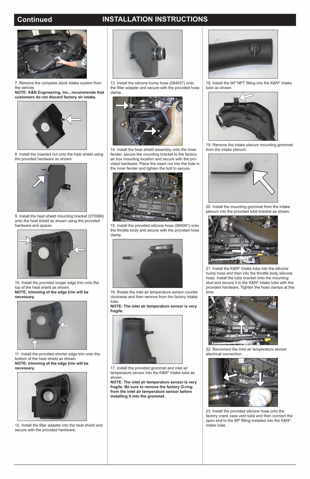
10. Install the provided longer edge trim onto the top of the heat shield as shown.NOTE: trimming of the edge trim will benecessary.
11. Install the provided shorter edge trim onto the bottom of the heat shield as shown.NOTE: trimming of the edge trim will benecessary.
12. Install the filter adapter into the heat shield and secure with the provided hardware.
13. Install the silicone hump hose (084057) onto the filter adapter and secure with the provided hose clamp.
14. Install the heat shield assembly onto the inner fender; secure the mounting bracket to the factory air box mounting location and secure with the pro-vided hardware. Place the insert nut into the hole in the inner fender and tighten the bolt to secure.
16. Rotate the inlet air temperature sensor counter clockwise and then remove from the factory intake tube.NOTE: The inlet air temperature sensor is very fragile.
17. Install the provided grommet and inlet air temperature sensor into the K&N® intake tube as shown.NOTE: The inlet air temperature sensor is very fragile. Be sure to remove the factory O-ring from the inlet air temperature sensor before installing it into the grommet.
15. Install the provided silicone hose (084091) onto the throttle body and secure with the provided hose clamp.
18. Install the 90º NPT fitting into the K&N® intake tube as shown.
19. Remove the intake plenum mounting grommet from the intake plenum.
20. Install the mounting grommet from the intake plenum into the provided tube bracket as shown.
21. Install the K&N® intake tube into the silicone hump hose and then into the throttle body silicone hose. Install the tube bracket onto the mounting stud and secure it to the K&N® intake tube with the provided hardware. Tighten the hose clamps at this time.
22. Reconnect the inlet air temperature sensor electrical connection.
23. Install the provided silicone hose onto thefactory crank case vent tube and then connect the open end to the 90º fitting installed into the K&N® intake tube.
9. Install the heat shield mounting bracket (070066) onto the heat shield as shown using the provided hardware and spacer.
8. Install the inserted nut onto the heat shield using the provided hardware as shown.
7. Remove the complete stock intake system from the vehicle.NOTE: K&N Engineering, Inc., recommends that customers do not discard factory air intake.
* FREE K&N® decal To register your warranty, please see us online at knfilters.com/register. FREE K&N® decal *
INSTALLATION INSTRUCTIONSContinuedROAD TESTING:
• 1455 CITRUS ST., P.O. BOX 1329, RIVERSIDE, CA., U.S.A. 92502 • TECH SERVICE 800-858-3333 • FAX 951-826-4001 • e-mail: [email protected]® • WWW: http://www.knfilters.com®
1. Start the engine with the transmission in neutral or park, and the parking brake engaged. Listen for air leaks or odd noises. For air leaks secure hoses and connections. For odd noises, find cause and repair before proceeding. This kit will function identically to the factory system except for being louder and much more responsive.
2. Test drive the vehicle. Listen for odd noises or rattles and fix as necessary.
3. If road test is fine, you can now enjoy the added power and performance from your kit.
4. K&N Engineering, Inc., requires cleaning the intake system’s air filter element every 100,000miles. When used in dusty or off-road environments, our filters will require cleaning moreoften. We recommend that you visually inspect your filter once every 25,000 miles to determine if the screen is still visible. When the screen is no longer visible some place on the filter element, it is time to clean it. To clean and re-oil, purchase our filter Recharger® service kit, part number 99-5050 or 99-5000 and follow the easy instructions.
26. It will be necessary for all K&N® high flow intake systems to be checked periodically for realignment, clearance and tightening of all connections. Failure to follow the above instructions or proper maintenance may void warranty.
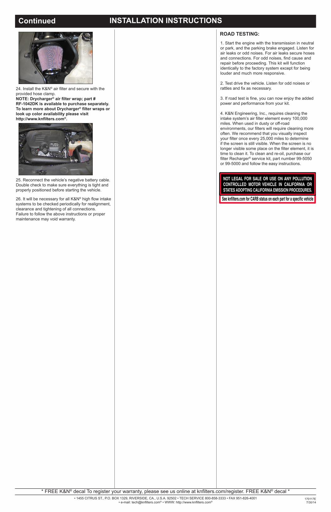
25. Reconnect the vehicle’s negative battery cable. Double check to make sure everything is tight and properly positioned before starting the vehicle.
24. Install the K&N® air filter and secure with the provided hose clamp.NOTE: Drycharger® air filter wrap; part #RF-1042DK is available to purchase separately. To learn more about Drycharger® filter wraps or look up color availability please visithttp://www.knfilters.com®.
170117E7/30/14