programmable timing computer - jegs.com · programmable timing computer pn 8981 mounting select a...
TRANSCRIPT

PROGRAMMABLE TIMING COMPUTERPN 8981
MOUNTING
Select a location away from excessive heat, near the MSD IgnitionControl and where the control knobs are easy to reach. First, installthe rubber mounting pads and sleeves to line up holes for drilling.Using the unit as a guide, mark the locations of the four mountingholes on the unit. Remove the unit and drill four 1/8" holes in thelocations marked. Install the unit using the four self tapping screws.
CYLINDER SELECT
The Timing Control must be programmed for your specific application.Cylinder Select: The Timing Computer is programmed for 8-cylinder operation, but can beprogrammed for use on 4 or 6-cylinder engines. This is easily accomplished by removing thesmall plastic cover with one Phillips screw located on the side of the Computer (Figure 2). Insidethere is a Red and Blue wire loop used to program the number of cylinders.
Parts Included In This Kit1 - Programmable Timing Computer4 - Retard Modules, 2°, 3°, 4° and 0°4 - Mounting Screws and Vibration Mounts
WWWWWARNING:ARNING:ARNING:ARNING:ARNING: During installation, disconnect the battery cables. When disconnecting thebattery, always remove the Negative cable first and install it last.
Note:Note:Note:Note:Note: This unit must be used with an ignition system without any type of mechanicaladvance. A crank trigger system or distributors with the mechanical advancelocked out must be used.
Note:Note:Note:Note:Note: An MSD Ignition Control must be used with the PN 8981.Note:Note:Note:Note:Note: Do not use a dial-back or digital timing light when programming the PN 8981.
Figure 2 Programming for the Number of Cylinders.
AUTOTRONIC CONTROLS CORPORATION • 1490 HENRY BRENNAN DR., EL PASO, TEXAS 79936 • (915) 857-5200 • FAX (915) 857-3344
Figure 1 InstallingMounting Pads.

2 INSTALLATION INSTRUCTIONS
AUTOTRONIC CONTROLS CORPORATION • 1490 HENRY BRENNAN DR., EL PASO, TEXAS 79936 • (915) 857-5200 • FAX (915) 857-3344
FEATURES AND ADJUSTING
The Programmable Timing Computer allows you to program an ignition curve for an enginewith locked out timing or a crank trigger. The Timing Computer also has two optional features.
Start Retard: This optional feature will retard the timing 20° during cranking to ease starting.It is activated when 12 volts is applied to the Violet wire and turns off (timing returns to thetotal timing) when the voltage is removed. Connect this wire to the wire that activates thestarter solenoid. Note: The start timing retards 20° from the total timing.
High Speed Retard: A small amount of retard at high rpm or in times of nitrous can improveperformance and save your engine from detonation caused by high cylinder pressures.This optional feature is adjustable with plug-in modules and is activated when the Gray wireis removed from ground. If this feature is not used, ground the Gray wire.
Timing Curve Adjustment ControlsThere are three adjustable potentiometers on the side of the Programmable Timing Computer.They are adjusted by loosening the lock nut and then turning the pot with a flat bladescrewdriver. All of the knobs are set at the full clockwise position at the factory, which meansthat they are Off and there is no timing curve. Figure 4 shows a typical timing curve.
All adjustments of the Timing Computer are taken from your Mechanical, or total timingsetting. The Mechanical timing is set by the position of the crank trigger or distributor.Before making any adjustments, be sure to have your mechanical timing set to yourspecifications.
Figure 3 Adjustment Features.
RPM: This is the rpm point inwhich the advance will begin.To set this, accelerate theengine to the rpm point thatyou want the advance to start.Turn the RPM control potcounterclockwise until thetiming begins to change.
Initial Timing: This adjuststhe timing setting where theengine idles. This amountcan be adjusted 20° fromwhere the mechanicaltiming is set. To adjust theinitial timing, turn the controlpot counterclockwise. It willretard the timing up to 20°from the mechanical timing.
Slope: This is the pointwhere the timing advancesto the mechanical timingagain. To set this, rev theengine up to the rpm pointthat the timing should becompletely in at. Turn theSlope control potcounterclockwise until thetiming begins to change.

INSTALLATION INSTRUCTIONS 3
AUTOTRONIC CONTROLS CORPORATION • 1490 HENRY BRENNAN DR., EL PASO, TEXAS 79936 • (915) 857-5200 • FAX (915) 857-3344
WIRING
RED This is the On/Off wire. Connects to switched 12 volts.
BLACK Connects to Ground.
YELLOW Trigger output. Connects to the MSD Ignition's White Wire.
TRIGGER INPUTS
WHITE
There are two input trigger circuits. The wires will never be connected at the same time.
Connects to points or the amplifier trigger wire.
GREEN/VIOLET2-Pin Connector
Connects to the magnetic pickup of the distributor or crank trigger. Greenis negative, Violet is positive.
RETARD WIRES
GRAY This wire activates the Step Retard when it is removed from ground.
Note: If the Step Retard is not going to be used, the Gray wire must be grounded or a Zerodegree module must be installed. If not, the max retard amount (20°) will be applied.
The following figures show the installation of the Timing Computer.
Figure 4 Typical Timing Curve.
Figure 4 shows a typical advance curve. The Mechanical timing is set at 35°. The initialtiming is set at 20° until 1,500 rpm where the timing begins to advance (rpm). The timingcontinues to advance until it reaches the mechanical (Slope) timing. Also, note the 20° startretard and a 3° high speed retard.
VIOLET This is the 20° Start Retard activation wire. It is activated when applied to 12 volts.
4 INSTALLATION INSTRUCTIONS
AUTOTRONIC CONTROLS CORPORATION • 1490 HENRY BRENNAN DR., EL PASO, TEXAS 79936 • (915) 857-5200 • FAX (915) 857-3344
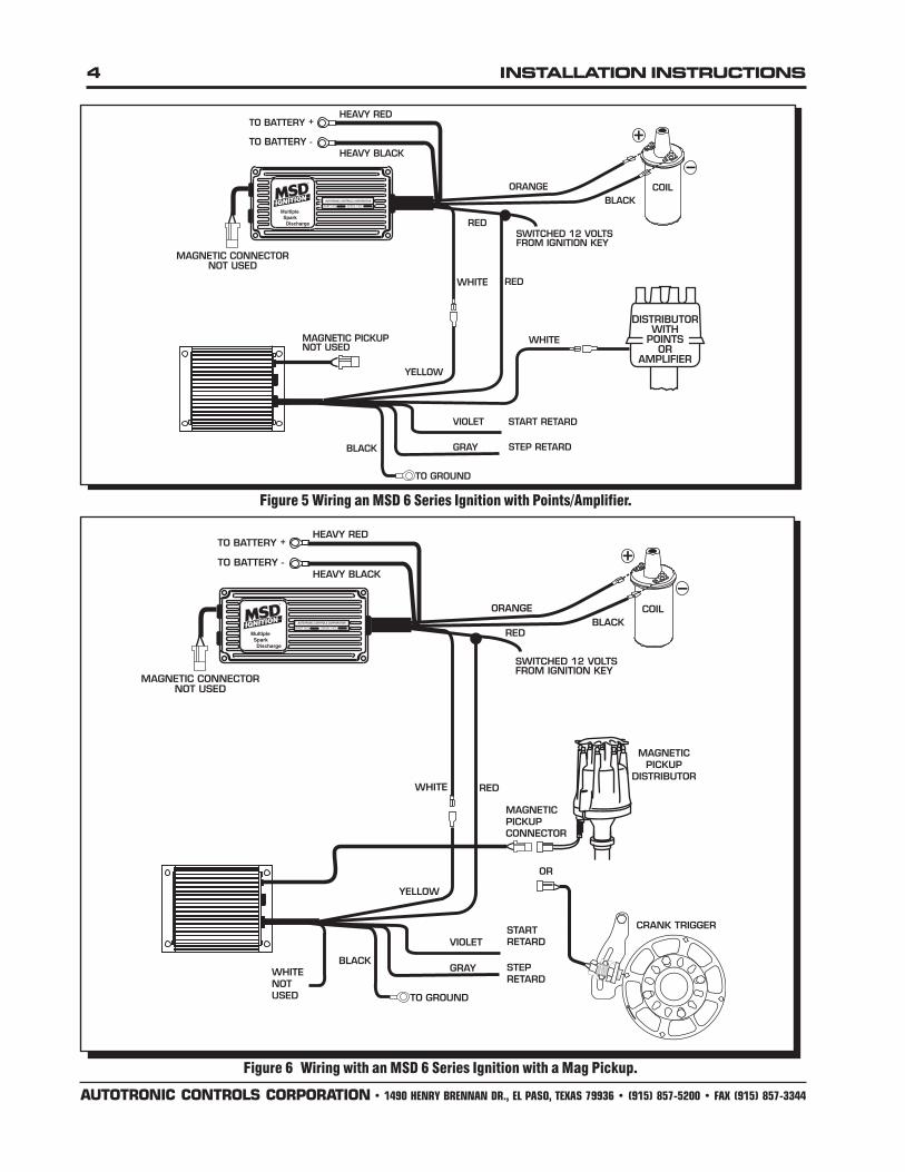
Figure 5 Wiring an MSD 6 Series Ignition with Points/Amplifier.
Figure 6 Wiring with an MSD 6 Series Ignition with a Mag Pickup.
INSTALLATION INSTRUCTIONS 5
AUTOTRONIC CONTROLS CORPORATION • 1490 HENRY BRENNAN DR., EL PASO, TEXAS 79936 • (915) 857-5200 • FAX (915) 857-3344
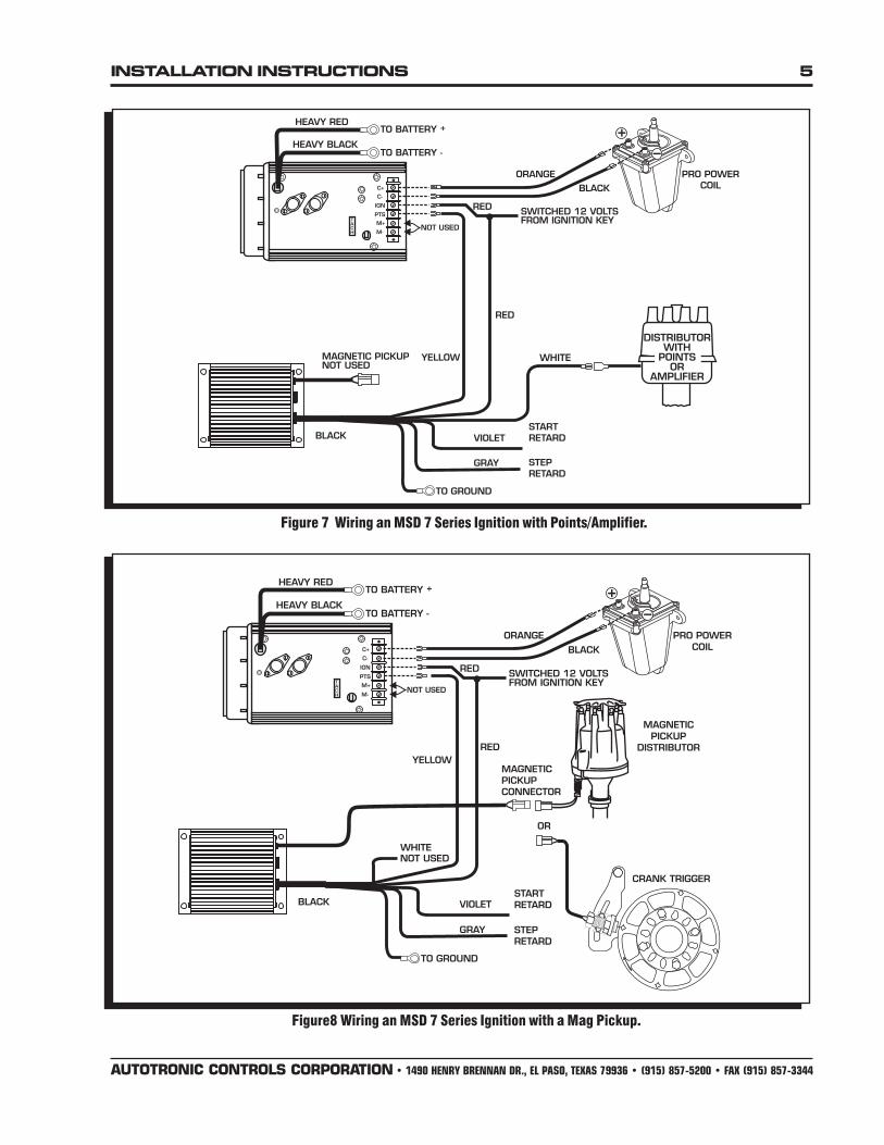
Figure8 Wiring an MSD 7 Series Ignition with a Mag Pickup.
Figure 7 Wiring an MSD 7 Series Ignition with Points/Amplifier.
6 INSTALLATION INSTRUCTIONS
AUTOTRONIC CONTROLS CORPORATION • 1490 HENRY BRENNAN DR., EL PASO, TEXAS 79936 • (915) 857-5200 • FAX (915) 857-3344
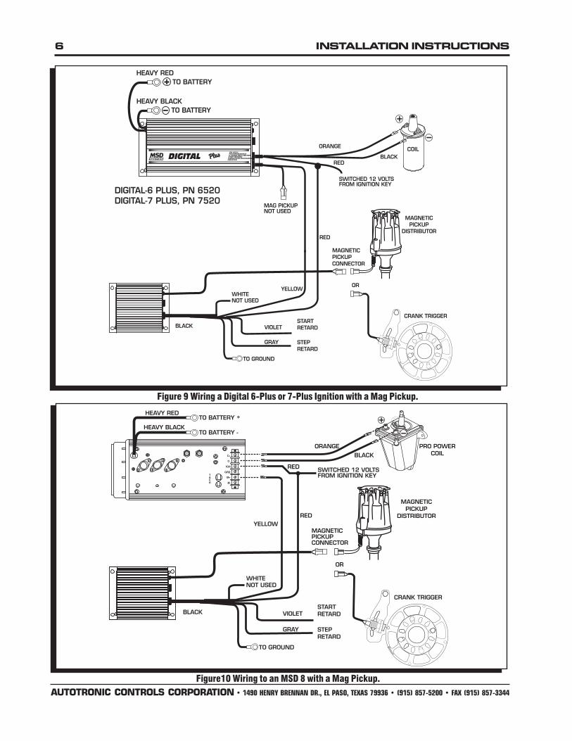
Figure 9 Wiring a Digital 6-Plus or 7-Plus Ignition with a Mag Pickup.
Figure10 Wiring to an MSD 8 with a Mag Pickup.
INSTALLATION INSTRUCTIONS 7
AUTOTRONIC CONTROLS CORPORATION • 1490 HENRY BRENNAN DR., EL PASO, TEXAS 79936 • (915) 857-5200 • FAX (915) 857-3344
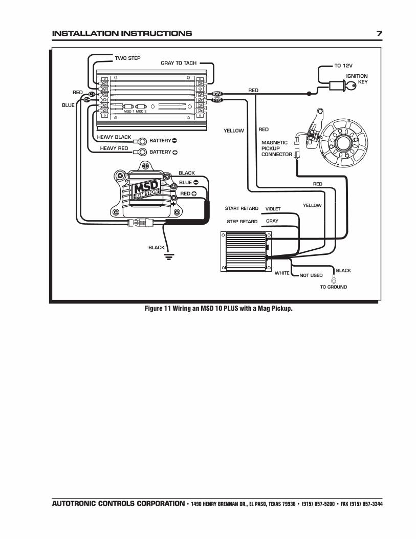
Figure 11 Wiring an MSD 10 PLUS with a Mag Pickup.
8 INSTALLATION INSTRUCTIONS
AUTOTRONIC CONTROLS CORPORATION • 1490 HENRY BRENNAN DR., EL PASO, TEXAS 79936 • (915) 857-5200 • FAX (915) 857-3344
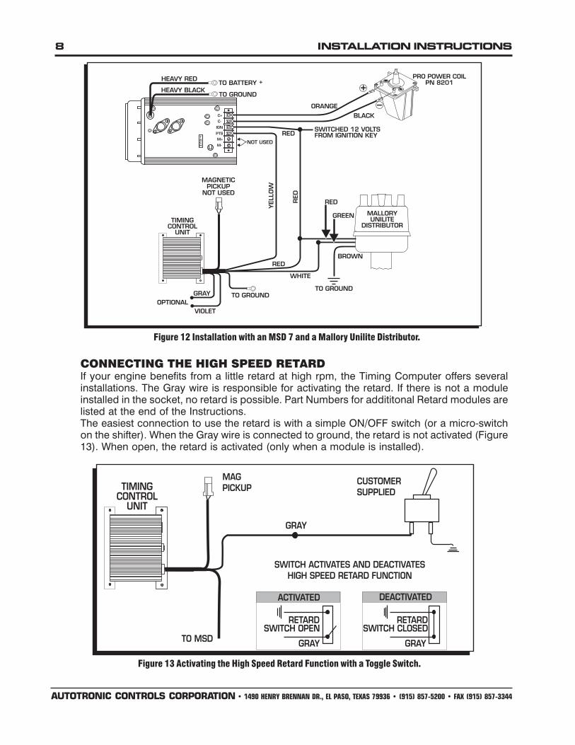
CONNECTING THE HIGH SPEED RETARDIf your engine benefits from a little retard at high rpm, the Timing Computer offers severalinstallations. The Gray wire is responsible for activating the retard. If there is not a moduleinstalled in the socket, no retard is possible. Part Numbers for addititonal Retard modules arelisted at the end of the Instructions.The easiest connection to use the retard is with a simple ON/OFF switch (or a micro-switchon the shifter). When the Gray wire is connected to ground, the retard is not activated (Figure13). When open, the retard is activated (only when a module is installed).
Figure 13 Activating the High Speed Retard Function with a Toggle Switch.
Figure 12 Installation with an MSD 7 and a Mallory Unilite Distributor.
INSTALLATION INSTRUCTIONS 9
AUTOTRONIC CONTROLS CORPORATION • 1490 HENRY BRENNAN DR., EL PASO, TEXAS 79936 • (915) 857-5200 • FAX (915) 857-3344
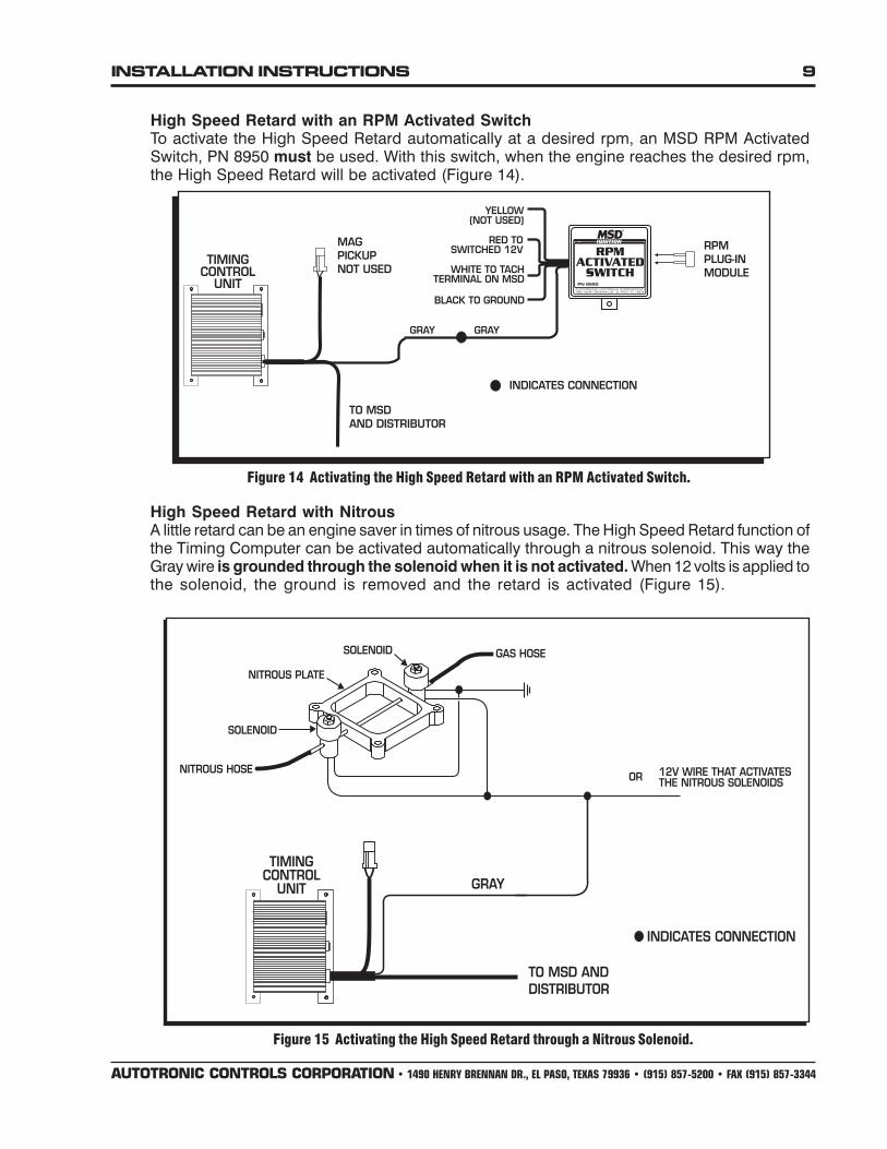
High Speed Retard with NitrousA little retard can be an engine saver in times of nitrous usage. The High Speed Retard function ofthe Timing Computer can be activated automatically through a nitrous solenoid. This way theGray wire is grounded through the solenoid when it is not activated. When 12 volts is applied tothe solenoid, the ground is removed and the retard is activated (Figure 15).
Figure 15 Activating the High Speed Retard through a Nitrous Solenoid.
High Speed Retard with an RPM Activated SwitchTo activate the High Speed Retard automatically at a desired rpm, an MSD RPM ActivatedSwitch, PN 8950 must be used. With this switch, when the engine reaches the desired rpm,the High Speed Retard will be activated (Figure 14).
Figure 14 Activating the High Speed Retard with an RPM Activated Switch.

10 INSTALLATION INSTRUCTIONS
AUTOTRONIC CONTROLS CORPORATION • 1490 HENRY BRENNAN DR., EL PASO, TEXAS 79936 • (915) 857-5200 • FAX (915) 857-3344
TECH NOTES________________________________________________________________________________________________________________________
________________________________________________________________________________________________________________________
________________________________________________________________________________________________________________________
________________________________________________________________________________________________________________________
________________________________________________________________________________________________________________________
________________________________________________________________________________________________________________________
________________________________________________________________________________________________________________________
________________________________________________________________________________________________________________________
________________________________________________________________________________________________________________________
________________________________________________________________________________________________________________________
________________________________________________________________________________________________________________________
________________________________________________________________________________________________________________________
________________________________________________________________________________________________________________________
________________________________________________________________________________________________________________________
________________________________________________________________________________________________________________________
________________________________________________________________________________________________________________________
________________________________________________________________________________________________________________________
________________________________________________________________________________________________________________________
________________________________________________________________________________________________________________________
________________________________________________________________________________________________________________________
________________________________________________________________________________________________________________________
________________________________________________________________________________________________________________________
________________________________________________________________________________________________________________________
________________________________________________________________________________________________________________________
________________________________________________________________________________________________________________________
________________________________________________________________________________________________________________________
________________________________________________________________________________________________________________________
________________________________________________________________________________________________________________________
________________________________________________________________________________________________________________________
Retard Module Kits Retard Selectors*1°, 2°, 3°, 4°, 5° PN 8777 0° - 11° PN 8676
5°, 6°, 7°, 8°, 9°, 10° PN 8776 0°/10° - 20° PN 867811°, 12°, 13°, 14°, 15° PN 877416°, 17°, 18°, 19°, 20° PN 8775
*Retard Selectors provide 11 different retard rates at the turn of a knob.

INSTALLATION INSTRUCTIONS 11
AUTOTRONIC CONTROLS CORPORATION • 1490 HENRY BRENNAN DR., EL PASO, TEXAS 79936 • (915) 857-5200 • FAX (915) 857-3344
TECH NOTES________________________________________________________________________________________________________________________
________________________________________________________________________________________________________________________
________________________________________________________________________________________________________________________
________________________________________________________________________________________________________________________
________________________________________________________________________________________________________________________
________________________________________________________________________________________________________________________
________________________________________________________________________________________________________________________
________________________________________________________________________________________________________________________
________________________________________________________________________________________________________________________
________________________________________________________________________________________________________________________
________________________________________________________________________________________________________________________
________________________________________________________________________________________________________________________
________________________________________________________________________________________________________________________
________________________________________________________________________________________________________________________
________________________________________________________________________________________________________________________
________________________________________________________________________________________________________________________
________________________________________________________________________________________________________________________
________________________________________________________________________________________________________________________
________________________________________________________________________________________________________________________
________________________________________________________________________________________________________________________
________________________________________________________________________________________________________________________
________________________________________________________________________________________________________________________
________________________________________________________________________________________________________________________
________________________________________________________________________________________________________________________
________________________________________________________________________________________________________________________
________________________________________________________________________________________________________________________
________________________________________________________________________________________________________________________
________________________________________________________________________________________________________________________
________________________________________________________________________________________________________________________
________________________________________________________________________________________________________________________
________________________________________________________________________________________________________________________
________________________________________________________________________________________________________________________
________________________________________________________________________________________________________________________
________________________________________________________________________________________________________________________
________________________________________________________________________________________________________________________
________________________________________________________________________________________________________________________
________________________________________________________________________________________________________________________

Limited Warranty
Autotronic Controls Corporation warrants MSD Ignition products to be free from defects in materialand workmanship under normal use and if properly installed for a period of one year from date of purchase.If found to be defective as mentioned above, it will be replaced or repaired if returned prepaid along withproof of date of purchase. This shall constitute the sole remedy of the purchaser and the sole liability ofAutotronic Controls Corporation. To the extent permitted by law, the foregoing is exclusive and in lieu ofall other warranties or representations whether expressed or implied, including any implied warranty ofmerchantability or fitness. In no event shall Autotronic Controls Corporation be liable for special orconsequential damages.
Service
In case of malfunction, this MSD component will be repaired free of charge according to the terms ofthe warranty. When returning MSD components for service, Proof of Purchase must be supplied for warrantyverification. After the warranty period has expired, repair service is charged based on a minimum andmaximum charge.
Send the unit prepaid with proof of purchase to the attention of: Customer Service Department,Autotronic Controls Corporation, 12120 Esther Lama, Suite 114, El Paso, Texas 79936.
When returning the unit for repair, leave all wires at the length in which you have them installed. Besure to include a detailed account of any problems experienced, and what components and accessoriesare installed on the vehicle.
The repaired unit will be returned as soon as possible after receipt, COD for any charges. (Groundshipping is covered by warranty). All units are returned regular UPS unless otherwise noted. For moreinformation, call the MSD Customer Service Line (915) 855-7123. MSD technicians are available from 8:00a.m. to 5:00 p.m. Monday - Friday (Mountain Time).
AUTOTRONIC CONTROLS CORPORATION • 1490 HENRY BRENNAN DR., EL PASO, TEXAS 79936 • (915) 857-5200 • FAX (915) 857-3344
FRM25004 Revised 05/03 Printed In U.S.A.
TECH NOTES________________________________________________________________________________________________________________________
________________________________________________________________________________________________________________________
________________________________________________________________________________________________________________________
________________________________________________________________________________________________________________________
________________________________________________________________________________________________________________________
________________________________________________________________________________________________________________________
________________________________________________________________________________________________________________________
________________________________________________________________________________________________________________________
________________________________________________________________________________________________________________________
________________________________________________________________________________________________________________________
________________________________________________________________________________________________________________________
________________________________________________________________________________________________________________________
________________________________________________________________________________________________________________________
________________________________________________________________________________________________________________________
________________________________________________________________________________________________________________________
________________________________________________________________________________________________________________________