manual disc conversion installation instructions - jegs.com · apply a little bearing grease to the...
TRANSCRIPT

62-72 B & E B60–76 A B
odyMopar ody Mopar
Manual Disc Conversion Installation Instructions
Special A-Body only parts shown below (In addition to parts above for A-Body cars, part # MDC66SD or MDC46SD)
Your new disc brake conversion kit can be bolted up with standard hand tools. The only tools you may not find in your toolbox are listed below.
2. Spring compressor (recommended for coil spring vehicles)
1. Ball joint fork or “pickle fork”
3. Drum brake tool (optional)
The Right Stuff Detailing Inc. v.2 Instruction Packet Tech Support: (800) 405-2000

Note: If you are interested in Power Coated Calipers or Drilled and Slotted Rotors for your car please give us a call. We have these upgrades available for exchange of non-installed components. We cannot exchange components that have been previously installed. Shipping charges will apply. Upgrades pictured.
ttention: Before A modifying, painting, or powder coating any part of this kit, please trial fit all components and check rim clearance. We recommend you run 15” or larger wheels with this kit. We do not support the use of 14” wheels on this kit.
oMModdiiffiieedd,, PPaaiinntteedd,, aanndd PPoowwddeerr CCooaatteedd ppaarrttss aarree nnoott rreettuurrnnaabbllee!!
The Right Stuff Detailing Inc. v.2 Instruction Packet Tech Support: (800) 405-2000

Kit Contents:
____ Pair of Rotors (BR51C for plain rotors, BR51ZDC rotors for drilled
___Pair of calipers (BC42N / BC43N, if powder coated calipers were
___Set of caliper brackets and spindles (DBSP03)
___Pair of Dust Shields (DBBP03)
___Steering Arm Hardware Kit (MHK04)
___Pair of Flex Hoses (FHK111 for regular, FHK111S for braided
___Wheel Bearing Kit (WBK62C)
___Adjustable Proportioning Valve (PV01)
___Master Cylinder (DBMC10 for Power Front Disc, DBMC15 for Power
___Pedal Rod (RC14)
___Upper Control Arms & Upper and Lower Ball Joints
___Instruction Packet
See the back page of the instruction booklet to review the “Pick Ticket”
and slotted rotors) _ selected there will be a letter pertaining to the color of the caliper within the part number as well, within this box of calipers will be a bag with the caliper mounting plates, hardware for the plates, anti-rattle rubber bands and anti-rattle rubber band mounting tab) _ _ _ _ stainless) _ _ _ Four Wheel Disc or Manual Front and Manual Four Wheel Disc) _ _ (UCA6076, A-Body Only) _ *used to pull your order.
The Right Stuff Detailing Inc. v.2 Instruction Packet Tech Support: (800) 405-2000
Disclaimer:
The Right Stuff values your safety above all things. For this reason, we recommend all brake systems and com nents be installed by professionals.
ad.
po
The installer of the brake parts is responsible for ensuring fitment and suitability of the parts for the vehicle it is being installed on. Brakes should be tested in a controlled open area with success before driving on the roIf you are unsure or uncomfortable with any part of your kit, please call for further instructions from our tech staff before driving.
The Right Stuff Detailing Inc. v.2 Instruction Packet Tech Support: (800) 405-2000

Installation Instructions:
Lower
egin by securely supporting the car on jack stands. Chock the rear wheels and set the s not roll. Always work on a flat, level surface. he brake system.
Joint will
nuts later. Use a heavy hammer to remove the tie rod end from the all joint fork or “pickle fork” may be needed to break things loose.
nscrew the hard line from the flex hose, being careful not to get brake fluid on painted ose out of the frame mounted
Assembly
1. Prepare the car Bparking brake to be sure vehicle doeRemove the wheels to gain access to t
2. Disconnect tie rod ends & Lower Ball Remove the cotter pin and castle nut that secures the tie rod to the steering arm. Youreuse the castle steering arm. A b
3. Disconnect front flex hoses Usurfaces. Remove the flex hose retaining clip and pull the hbracket.
The Right Stuff Detailing Inc. v.2 Instruction Packet Tech Support: (800) 405-2000

4. Remove drum brake assemblies o remove the old drum brake assemblies you need to compress the coil springs. We
o handle the spring to the vehicle!
til all pressure is released from the control arm the upper ball joint
ove the spindle
5. Inspect suspension components Now is the time to clean up and inspect your suspension components. Check the inner
. Inspect the rubber ost automotive parts
Thighly recommend the use of a spring compression tool. Failure tproperly can result in serious injury to you and damage Preferred method for coil springs:
a. Remove the shock absorber b. Install the spring compressor following the directions supplied with the tool c. Compress the spring und. Remove the cotter pin and castle nut frome. Keep the castle nut for reuse later f. Use a ball joint fork to release the upper ball joint from the spindle g. Raise the upper control arm up out of the way h. Repeat steps “d” and “f” to release the lower ball joint and rem
assembly
and outer tie rod ends and ball joints for wear and replace if neededboots for cracks or tears. Universal replacements are available at mstores.
The Right Stuff Detailing Inc. v.2 Instruction Packet Tech Support: (800) 405-2000
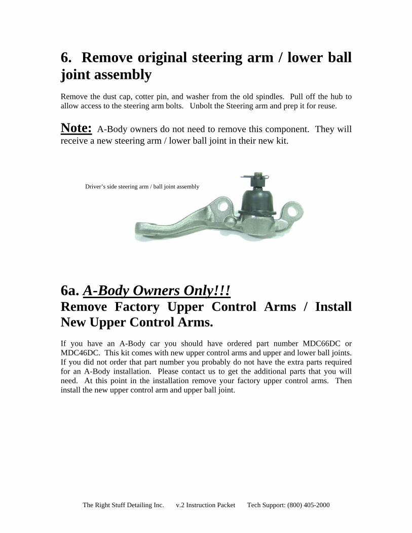
6. Remove original steering arm / lower ball
pin, and washer from the old spindles. Pull off the hub to llow access to the steering arm bolts. Unbolt the Steering arm and prep it for reuse.
joint assembly Remove the dust cap, cotter a
ote:N A-Body owners do not need to remove this component. They will receive a new steering arm / lower ball joint in their new kit.
Driver’s side steering arm / ball joint assembly
a. A-Body Owners Only!!!
6Remove Factory Upper Control Arms / Install
e ordered part number MDC66DC or DC46DC. This kit comes with new upper control arms and upper and lower ball joints.
New Upper Control Arms. If you have an A-Body car you should havMIf you did not order that part number you probably do not have the extra parts required for an A-Body installation. Please contact us to get the additional parts that you will need. At this point in the installation remove your factory upper control arms. Then install the new upper control arm and upper ball joint.
The Right Stuff Detailing Inc. v.2 Instruction Packet Tech Support: (800) 405-2000

7. Bolt together the new spindle assembly Attach the new caliper bracket to the spindle with the supplied
nce the brackets are on, you need to determine if you want front or rear mounted
Front Back
Driver’s side spindle assembly (rear mounted calipers) pictured above
hardware. The machined side of the bracket should face the spindle as illustrated to the right. Torque the bolts to 95 ft./lbs. Be sure you use the correct bracket and spindle. Both the spindles and the brackets are marked left or right.
Ocalipers. Most application use rear mounted calipers. If you want to run front mounted calipers, you need to reverse the spindles (left hand to right hand and vise versa). One of the determining factors of front or rear mount is the final flex hose routing. Test fit the spindles as both a front mount and a rear mount to see which setup would give you the best flex hose routing to the factory flex hose frame bracket. After you have determined if you are going to front or rear mount your calipers bolt up the old steering arm assembly (or new steering arms for A-Body owners) and torque the hardware to the specifications provided in the factory assembly manual.
The Right Stuff Detailing Inc. v.2 Instruction Packet Tech Support: (800) 405-2000

8. Install the new disc brake spindles Place the lower ball joint into the lower control arm and attach it with the original castle
ull the upper control arm down and insert the upper ball joint into place. Attach the
Front mounted caliper setup shown in photo above
ou are now ready to release the pressure on the coil spring. If you used a spring
the hardware supplied with
nut. Torque the nut to the specifications provided in the assembly manual. Fix it in place with the new cotter pin supplied with your kit. Pupper ball joint with the original castle nut. Torque the nut to the specifications provided in the assembly manual. Fix it in place with the new cotter pin supplied with your kit. Place the tie rod end back into the steering arm and fasten it with the original castle nut. Torque the nut to the specifications provided in the assembly manual. Fix it in place with the new cotter pin supplied with your kit.
9. Release the pressure on the coil spring or torsion bar Ycompressor, you can release it slowly and reinstall the shock absorber.
10. Install the backing plates
lace the backing plate over the spindle and fasten it with Pyour kit.
The Right Stuff Detailing Inc. v.2 Instruction Packet Tech Support: (800) 405-2000
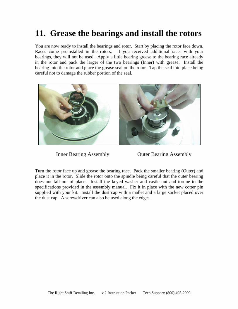
11. Grease the bearings and install the rotors You are now ready to install the bearings and rotor. Start by placing the rotor face down.
Inner Bearing Assembly Outer Bearing Assembly
urn the rotor face up and grease the bearing race. Pack the smaller bearing (Outer) and
Races come preinstalled in the rotors. If you received additional races with your bearings, they will not be used. Apply a little bearing grease to the bearing race already in the rotor and pack the larger of the two bearings (Inner) with grease. Install the bearing into the rotor and place the grease seal on the rotor. Tap the seal into place being careful not to damage the rubber portion of the seal.
Tplace it in the rotor. Slide the rotor onto the spindle being careful that the outer bearing does not fall out of place. Install the keyed washer and castle nut and torque to the specifications provided in the assembly manual. Fix it in place with the new cotter pin supplied with your kit. Install the dust cap with a mallet and a large socket placed over the dust cap. A screwdriver can also be used along the edges.
The Right Stuff Detailing Inc. v.2 Instruction Packet Tech Support: (800) 405-2000
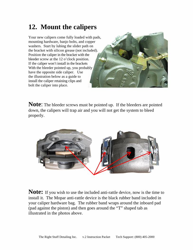
12. Mount the calipers Your new calipers come fully loaded with pads,
).
y
ust be pointed up. If the bleeders are pointed
mounting hardware, banjo bolts, and copper washers. Start by lubing the slider path on the bracket with silicon grease (not includedPosition the caliper in the bracket with the bleeder screw at the 12 o’clock position. If the caliper won’t install in the brackets With the bleeder pointed up, you probablhave the opposite side caliper. Use the illustration below as a guide to install the caliper retaining clips and bolt the caliper into place.
Note: The bleeder screws mdown, the calipers will trap air and you will not get the system to bleed properly.
Note: install it. The Mopar anti-rattle device is the black rubber band included in your caliper hardware bag. The rubber band wraps around the inboard pad (pad against the piston) and then goes around the “T” shaped tab as illustrated in the photos above.
If you wish to use the included anti-rattle device, now is the time to
The Right Stuff Detailing Inc. v.2 Instruction Packet Tech Support: (800) 405-2000
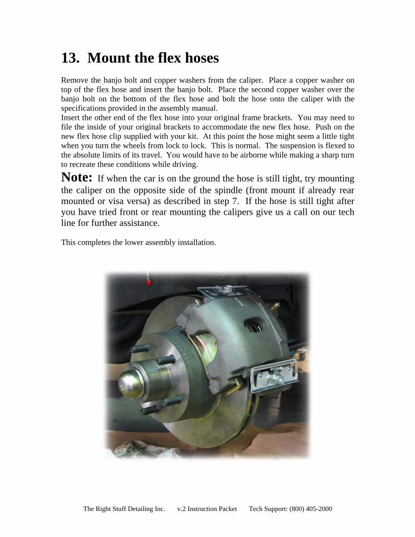
13. Mount the flex hoses
p of the flex hose and insert the banjo bolt. Place the second copper washer over the
modate the new flex hose. Push on the
bly installation.
Remove the banjo bolt and copper washers from the caliper. Place a copper washer on tobanjo bolt on the bottom of the flex hose and bolt the hose onto the caliper with the specifications provided in the assembly manual. Insert the other end of the flex hose into your original frame brackets. You may need to file the inside of your original brackets to accomnew flex hose clip supplied with your kit. At this point the hose might seem a little tight when you turn the wheels from lock to lock. This is normal. The suspension is flexed to the absolute limits of its travel. You would have to be airborne while making a sharp turn to recreate these conditions while driving.
Note: If when the car is on the ground the hose is still tight, try mounting the caliper on the opposite side of the spindle (front mount if already rear mounted or visa versa) as described in step 7. If the hose is still tight after you have tried front or rear mounting the calipers give us a call on our tech line for further assistance. This completes the lower assem
The Right Stuff Detailing Inc. v.2 Instruction Packet Tech Support: (800) 405-2000
Upper Assembly
1. Remove the old master cylinder assembly Remove the master cylinder brake lines being careful not to get fluid on any painted surfaces. Remove the eyelet from the pedal rod under the dash. If your original system was power, you should be able to remove the booster mounting nuts from the firewall and remove the booster/master assembly. If your original system was not power, simply remove the master cylinder mounting nuts from the firewall and remove the master cylinder.
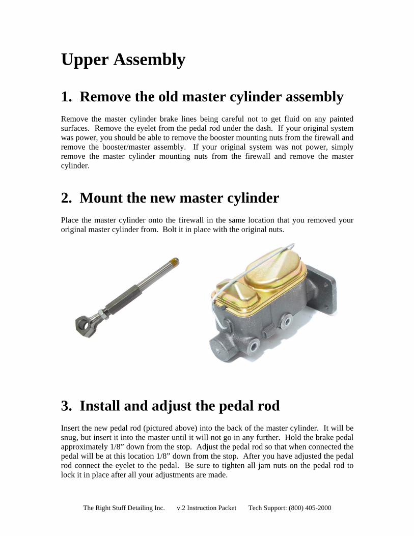
2. Mount the new master cylinder
Place the master cylinder onto the firewall in the same location that you removed your original master cylinder from. Bolt it in place with the original nuts.
3. Install and adjust the pedal rod Insert the new pedal rod (pictured above) into the back of the master cylinder. It will be snug, but insert it into the master until it will not go in any further. Hold the brake pedal approximately 1/8” down from the stop. Adjust the pedal rod so that when connected the pedal will be at this location 1/8” down from the stop. After you have adjusted the pedal rod connect the eyelet to the pedal. Be sure to tighten all jam nuts on the pedal rod to lock it in place after all your adjustments are made.
The Right Stuff Detailing Inc. v.2 Instruction Packet Tech Support: (800) 405-2000

4. Install the Adjustable Proportioning Valve Your disc conversion includes an adjustable proportioning valve. This valve controls the pressure to the rear brakes. This valve will need to be spliced into your front to rear brake line. This would be the line that runs from the distribution block on your frame under the master to the flex hose in the rear of your car. If you have purchased a disc brake conversion brake line kit from us the provision for this valve should already be in the front to rear line. After you have bleed the brake system in the following step adjust the valve using the following procedure. You simply open it all the way up by turning it as far counter clockwise as it will go. Then do a couple of test panic stops with your car in a safe area like an empty parking lot. If the rear brakes do not lock up while doing this then you are all set, you do not need to further adjust the valve. If your rear brakes do lock up during the panic stop test then you need to adjust the valve. To do this turn the valve clockwise to reduce the pressure to the rear brakes, then do another panic stop test. Continue this procedure until the rear brakes no longer lock up during a panic stop. 5. Bleeding the system Working your way forward from the wheel farthest from the master cylinder will help insure a good bleed and a firm pedal. It is important to bleed the system in the following order:
1. Right Rear 2. Left Rear 3. Right Front 4. Left Front
If you have a spongy pedal, be sure the bleeder screws are pointed up and try re-bleeding the system.
The Right Stuff Detailing Inc. v.2 Instruction Packet Tech Support: (800) 405-2000
Technical Support We want your conversion project to go smoothly. Double check that you have followed these instructions correctly and those included with any upgrade components you may have purchased. If you need additional help getting your new disc brakes to function properly, we’re here for you. You can visit our website at www.GetDiscBrakes.com for Tech Tips, Tricks & Videos. If you cannot find the assistance you need from that source feel free to send us an email from the Tech support section of the website for priority service. If you are still unable to get the help you need, please feel free to give us a call at (800) 405-2000.
Thank You for Your Business!
No part of this document may be reproduced without written permission of The Right Stuff Detailing Inc. The information contained in this document
is based on information we believe to be true and reliable, however the accuracy or completeness thereof is not guaranteed.
The Right Stuff Detailing Inc. v.2 Instruction Packet Tech Support: (800) 405-2000
Pick Ticket:
The Right Stuff Detailing Inc. v.2 Instruction Packet Tech Support: (800) 405-2000