unisteer® performance products - jegs.com · page 1 656410 unisteer® performance products...
TRANSCRIPT
Page 1 656410
UNISTEER® Performance Products
’60-’72 Chevrolet C10 Power Rack & Pinion Kit Instructions for 8011740-01, 8011920-01, 8011650-01, &
8011900-01 Rack and Pinion Kit
*USE ONLY POWER STEERING FLUID IN SYSTEM. DO NOT USE ATF. *ALTHOUGH THIS KIT IS FAIRLY SIMPLE TO INSTALL, SOME MODIFICATIONS MAYBE NECESSARY. *BEFORE STARTING INSTALLATION, PLEASE BE AWARE OF THE MODIFICATIONS THAT ARE NEEDED TO INSTALL. *ALSO BE AWARE THAT THERE ARE APPLICATION/PROVISIONS NEEDED IN ORDER TO INSTALL. PLEASE READ ALL INSTRUCTIONS FIRST. *A TWO GROOVE WATER PUMP PULLEY IS REQUIRED. DUE TO VARIABLES OUTSIDE OUR CONTROL THESE KITS MAY NOT FIT ALL APPLICATIONS. ALSO, PLEASE VERIFY KIT WILL FIT YOUR APPLICATION BEFORE ALTERING VEHICLE.
Full refund will NOT be granted to any kits that are damaged, scratched, or altered in any fashion.

Page 2 656410
KIT CONTENTS:
# Part Number Description Quantity
1 8011800-01, 8011890-01, 8011770-01, or 8011910-01
Rack and Pinion Unit w/bracket 1
2 231490 Rack and Pinion Mounting Bolts 3/8” – 16 x 1 ½ ” Hex Bolt 2
3 8020940 Outer Tie Rod Ends 2
4 200850 5/16 ” Flat Washers Zink 4
5 120490 3/8” – 16 Lock Nuts 2
6 8050760 Shaft Support Bracket w/ Nut (Not in All Kits) 1
7 8020790 Remote Pump Reservoir 1
8 8026340 Chevy C10 Hose Kit w/ Hose Clamp & Cover 1
9 8061170 C-5 TC Pump Kit for Chevy c10 1
10 543090 5.875” DD Shaft (9/16-30 Spline X Blank) (Not in All Kits) 1
11 546210 9” DD Shaft (9/16-30 Spline X Notch) (Not in All Kits) 1
12 8026930 Bracket Steering Shaft (Not in All Kits) 1
13 8050500 U-Joint ¾-36 X 9/16-30 (Not in All Kits) 1
14 8050300 U-Joint ¾-DD X ¾-DD 1
15 8050250 U-Joint 9/16-30 X ¾-DD (Not in All Kits) 1
16 622170 Install Kit 1
17 547370 16.6” DD Shaft (9/16-30 Spline X Notch) (Not in All Kits) 1
18 8050360 U-Joint ¾ X 9/16-30 (Not in All Kits) 1
1
8
7
10
16 3
4
6
12 13 14 15 5
9
11
2

Page 3 656410
1960-1972 Chevrolet C10 Rack and Pinion Installation 1. Raise car off ground. Remove the outer tie rod end cotter pins. Remove tie rod
nuts. Remove the idler arm mounting bolts off of the passenger side of the frame
by removing the thru bolts.
2. Remove the pinch bolt from the input shaft on the steering box. This will allow
for the gearbox to be completely removed after removing the three bolts holding it
to the frame.
3. Remove all stock steering linkage from the vehicle.

Page 4 656410
4. With stock steering removed, thread supplied 11/16-18 LH jam nuts onto threads.
Run jam nuts all the way till they are at the ends of the threads. At this point
thread the supplied ends into new tie rod adjusting bars.
5. Now to install your new kit. With supplied hardware (2: ½-13 bolts and 2: 3/8-
16 bolts). Bolt new R&P kit up into frame. Note: ½” bolts are used in drivers
side and 3/8” bolts are for passenger side.
6. With new R&P system bolted into truck, its time to hook up the steering. Bolt tie
rod ends into spindles.

Page 5 656410
1960-1966 shaft kit only
1. Make a mark on the steering shaft 1” down from clamp on upper end of shaft
(located where the shaft comes out of the firewall).
2. Cut steering shaft on 1” mark and remove the lower part of the stock steering
shaft.
3. Install new intermediate shaft kit on the rack using the lower u-joint. Slide the
upper u-joint onto the exposed remaining column shaft. Slide the intermediate
shaft into the upper u-joint. Note: make sure end of existing steering shaft is flush
with inside of u-joint. Tighten set screw on u-joint against the shaft with the u-
joints phased 90 Degrees off one another.
4. With supplied drill bit, drill a hole thru the u-joint and shaft, using the pre drilled
hole as a pilot.
Page 6 656410
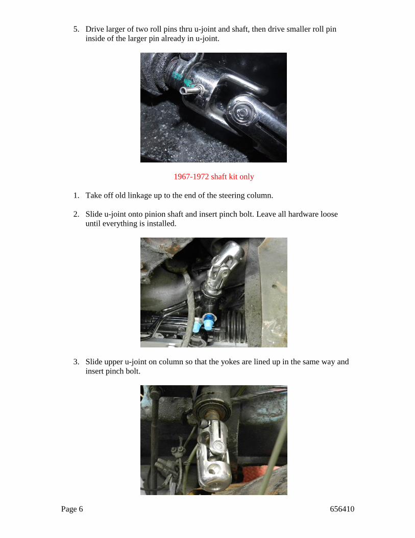
5. Drive larger of two roll pins thru u-joint and shaft, then drive smaller roll pin
inside of the larger pin already in u-joint.
1967-1972 shaft kit only
1. Take off old linkage up to the end of the steering column.
2. Slide u-joint onto pinion shaft and insert pinch bolt. Leave all hardware loose
until everything is installed.
3. Slide upper u-joint on column so that the yokes are lined up in the same way and
insert pinch bolt.

Page 7 656410
4. Slide the longer shaft into the upper u-joint and lock it in with the pinch bolt.
5. Slide support bearing with bracket up shaft. Line bracket up with holes on frame
as pictured and bolt bracket down.
6. Insert middle joint with lower shaft so that the yokes on the joint are facing the
same direction as the lower and upper (marked in red in the picture). You will
have to trim the lower shaft to fit. Make sure all joints are lined up correctly and
the support bearing is adjusted out where it needs to be before making your cut.
Then grind a notch for the pinch bolt. Re-assemble the shaft kit, check for binds,
and then tighten everything down.
Page 8 656410
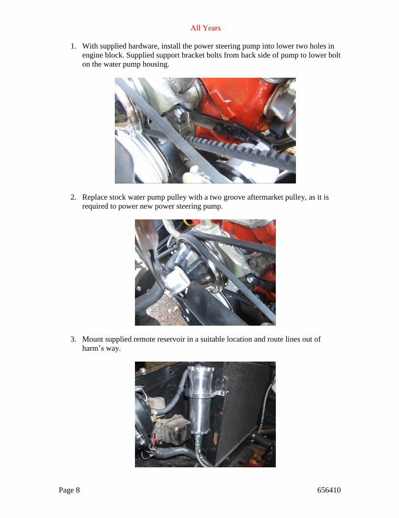
All Years
1. With supplied hardware, install the power steering pump into lower two holes in
engine block. Supplied support bracket bolts from back side of pump to lower bolt
on the water pump housing.
2. Replace stock water pump pulley with a two groove aftermarket pulley, as it is
required to power new power steering pump.
3. Mount supplied remote reservoir in a suitable location and route lines out of
harm’s way.

Page 9 656410
4. Hook power steering lines up, Pressure
line goes to top port (blue fitting) on
rack housing. Return line is the lower
port on the rack (silver fitting) which
goes to lower #6 fitting on the remote
reservoir. Large #10 line goes from
large port on the reservoir to nipple on
pump and secured with supplied hose
clamp.
5. By eye, line up steering of truck by adjusting the toe at the tie rod ends. After
installation it will be necessary to have your vehicle professionally aligned. Toe
adjustment is easy by just leaving the jam nut loose and turning the inner tie rod.
Then tighten up the jam nut.
6. If steering wheel isn’t straight when wheels are in the straight forward location
after your professional alignment, it may be necessary to remove your steering
wheel and reinstall it in the neutral position.
7. Install proper length pump belt to match
your application requirements. It will be
necessary to reroute your belts from
your water pump to your alternator.
Your crank, water pump and power
steering pump will be separate.
8. Top off power steering fluid level in pump reservoir. Start vehicle; keep running
for 15 seconds, shut vehicle off. “Do Not” turn wheels during this period.
9. Top off power steering fluid level and start vehicle. Cycle the steering back and
forth “Slowly” for a few minutes to allow the new system to bleed any air from
the lines. Note: Make sure your reservoir does not empty during steps 8 & 9.
If you have any questions or problems regarding this product please contact:
UNISTEER® Performance Products
1555 Enterprise Parkway Twinsburg OH 44087
800-338-9080
11/07/2011 Revised on 12/02/2013
Copyright © 2011 by Maval Manufacturing Corporation All rights reserved.
No part of these materials can be reproduced or utilized in any form or by any means,
electronic or mechanical, including photocopying, recording or by any information storage
and retrieval system, without permission in writing from Maval Manufacturing Corporation.