evaluation of rapid electric battery charging techniques
TRANSCRIPT

UNLV Theses, Dissertations, Professional Papers, and Capstones
2009
Evaluation of rapid electric battery charging techniques Evaluation of rapid electric battery charging techniques
Ronald Baroody University of Nevada Las Vegas
Follow this and additional works at: https://digitalscholarship.unlv.edu/thesesdissertations
Part of the Power and Energy Commons
Repository Citation Repository Citation Baroody, Ronald, "Evaluation of rapid electric battery charging techniques" (2009). UNLV Theses, Dissertations, Professional Papers, and Capstones. 156. http://dx.doi.org/10.34917/1392506
This Thesis is protected by copyright and/or related rights. It has been brought to you by Digital Scholarship@UNLV with permission from the rights-holder(s). You are free to use this Thesis in any way that is permitted by the copyright and related rights legislation that applies to your use. For other uses you need to obtain permission from the rights-holder(s) directly, unless additional rights are indicated by a Creative Commons license in the record and/or on the work itself. This Thesis has been accepted for inclusion in UNLV Theses, Dissertations, Professional Papers, and Capstones by an authorized administrator of Digital Scholarship@UNLV. For more information, please contact [email protected].

EVALUATION OF RAPID ELECTRIC BATTERY CHARGING
TECHNIQUES
By
Ronald Baroody
Bachelor of Science University of Nevada, Las Vegas
2005
A thesis submitted in partial fulfillment of the requirements for the
Master of Science in Engineering Department of Electrical and Computer Engineering
Howard R. Hughes College of Engineering
Graduate College University of Nevada, Las Vegas
December 2009

Copyright by Ronald Baroody 2010 All Rights Reserved

THE GRADUATE COLLEGE We recommend that the thesis prepared under our supervision by Ronald Baroody entitled Evaluation of Rapid Electric Battery Charging Techniques be accepted in partial fulfillment of the requirements for the degree of Master of Science Engineering Yahia Baghzouz, Committee Chair Yingtao Jiang, Committee Member Emma Regentova, Committee Member Robert Boehm, Graduate Faculty Representative Ronald Smith, Ph. D., Vice President for Research and Graduate Studies and Dean of the Graduate College December 2009
ii

ABSTRACT
Evaluation of Rapid Electric Battery Charging Techniques
by
Ronald Baroody
Dr. Yahia Baghzouz, Examination Committee Chair Professor of Electrical Engineering
University of Nevada, Las Vegas
Battery powered electric vehicles are gaining popularity worldwide. This is trend is
driven by several factors including the need to reduce air and noise pollution, and
dependence on fossil fuels. The main drawback of today’s electric vehicle is its limited
range, and the long time duration that is required to charge the electric batteries. This
thesis addresses the latter problem.
In recent years, significant progress (through research and development) has been
made to accelerate the charging time of the electric vehicle batteries through pulse
charging rather than supplying continuous current and/or voltage. Some patented fast
charging techniques demonstrated reduced charging times from 8 hours down to 45
minutes, and the current goal is to reduce this to the 10‐minute range. This thesis will
evaluate the published fast charging techniques in terms of their efficiency, accuracy of
state of charge, threat of overcharge and impact of life cycle. The merits of the various
battery interrogation techniques will be analyzed through modeling and computer
simulation.
iii

ACKNOWLEDGEMENTS
First and foremost, I would like to sincerely thank and extend my deepest gratitude to
my advisor and thesis chair, Professor Yahia Baghzouz for his valuable guidance
throughout my entire educational journey at the University of Nevada, Las Vegas
(UNLV). Dr. Baghzouz was always there to lend his educational iron fist when things got
complicated and hard to understand.
I would also like to express tremendous appreciation and extend my gratitude to my
thesis committee member, Distinguished Professor Dr. Robert Boehm. His exemplary
works on research and commitment to ethics have been sources of inspiration making it a
privilege to work with him.
I also wish to thank the members of my thesis committee, Dr. Emma Regentova and
Dr. Yingtao Jiang, for their support. I would like to extend many thanks to my colleagues
at UNLV for their unconditional support in helping me.
I am grateful to my wife, Barbara for her understanding, endless patience and
encouragement at the time, when it was most required. Last but certainly not least, I am
forever indebted to the love and care of my parents who made me capable to accomplish
their expectations.
iv

TABLE OF CONTENTS ABSTRACT ....................................................................................................................... iii ACKNOWLEDGEMENTS ............................................................................................... iv LIST OF TABLES ............................................................................................................ vii LIST OF FIGURES ......................................................................................................... viii CHAPTER 1 INTRODUCTION ....................................................................................... 1 1.1 Battery Definition ......................................................................................................... 1 1.2 Battery Classification .................................................................................................... 6 CHAPTER 2 SECONDARY CELLS ................................................................................. 9 2.1 Common Types of Secondary Cells ............................................................................. 9 2.2 Reversible Charge/Discharge Property of Secondary Cells ....................................... 16 2.3 Battery Charge/Discharge Performance Factors ......................................................... 16 CHAPTER 3 BATTERY CHARGING TECHNIQUES ................................................. 18 3.1 Introduction ................................................................................................................. 18 3.2 Conventional Charging Techniques ............................................................................ 18
3.2.1 Constant Current Trickle (CCT) Charging Technique ..................................... 18 3.2.3 Constant Current Constant Voltage (CCCV) Charging Technique .................. 19
3.3 Pulse Charging (PC) Technique.................................................................................. 19 3.4 State of The Art Charging Technique ......................................................................... 20 CHAPTER 4 FAST CHARGING TECHNIQUES EVALUATION .............................. 21 4.1 Introduction ............................................................................................................... 21 4.2 Control Circuitry for Termination of Rapid Battery Charging ................................... 21 4.3 Method and Apparatus for Rapid Battery Charging ................................................... 23 4.4 Method and Apparatus for Rapidly Charging and Reconditioning a Battery ............. 25 4.5 Rapid Charging of a Battery by Applying Alternating Pulsed Large Current without a High Temperature ............................................................................................................. 27 4.6 Battery State of Charge Detector With Rapid Charging Capability and Method ....... 28 4.7 Rapid Battery Charging Method and Apparatus ......................................................... 31 CHAPTER 5 SECONDARY BATTERY MODELING TECHNIQUES ....................... 33 5.1 Electrical Battery Model for Use in Dynamic Electric Vehicle Simulations ............. 33 5.2 An Enhanced Dynamic Battery Model of Lead-acid Batteries using Manufacturers' Data ................................................................................................................................... 34 5.3 Design of Interface Circuits with Electrical Battery Models ...................................... 36 5.4 A Battery Model Including Hysteresis for State-Of-Charge Estimation in Ni-Mh Battery ............................................................................................................................... 38 CHAPTER 6 CONCLUSION AND FUTURE DIRECTIONS ....................................... 41 6.1 As it Relates to Fast Charging Techniques ................................................................. 41
v

vi
6.2 As It Relates to Battery Modeling for Fast Charging Simulations ............................. 42 BIBLIOGRAPHY ............................................................................................................. 55 VITA ................................................................................................................................. 58
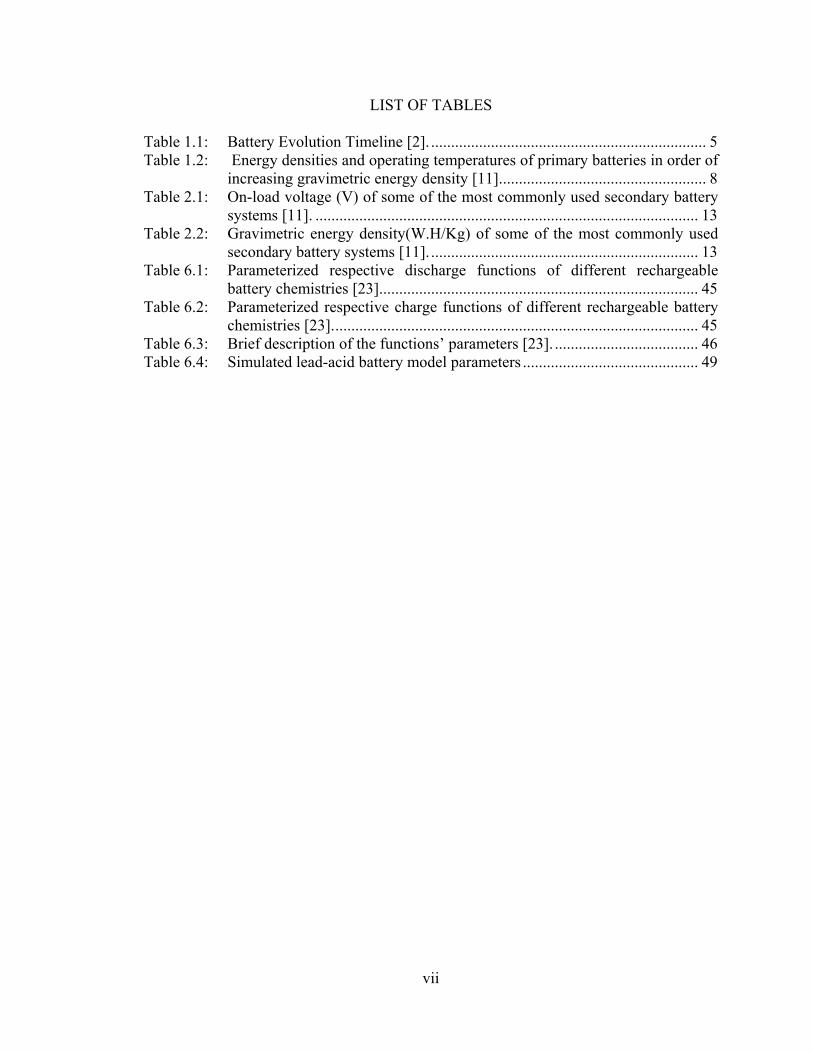
LIST OF TABLES
Table 1.1: Battery Evolution Timeline [2]. ..................................................................... 5 Table 1.2: Energy densities and operating temperatures of primary batteries in order of increasing gravimetric energy density [11]. ................................................... 8 Table 2.1: On-load voltage (V) of some of the most commonly used secondary battery systems [11]. ................................................................................................ 13 Table 2.2: Gravimetric energy density(W.H/Kg) of some of the most commonly used secondary battery systems [11]. ................................................................... 13 Table 6.1: Parameterized respective discharge functions of different rechargeable battery chemistries [23]. ............................................................................... 45 Table 6.2: Parameterized respective charge functions of different rechargeable battery chemistries [23]. ........................................................................................... 45 Table 6.3: Brief description of the functions’ parameters [23]. .................................... 46 Table 6.4: Simulated lead-acid battery model parameters ............................................ 49
vii

LIST OF FIGURES
Figure 1.1 Basic components of an electrochemical cell [1]. ......................................... 1 Figure 1.2: Cross Section of a Baghdad Battery [8]. ........................................................ 3 Figure 1.3: Improvement in primary battery performance at 21°C since 1946 [11]. ....... 7 Figure 2.1: Gravimetric energy density of secondary batteries at a 5 hour discharge rate [11]. .............................................................................................................. 14 Figure 4.1: Control Circuitry for Termination of Rapid Battery Charging [13]. ........... 22 Figure 4.2: Samsioe’s patented charging apparatus [14]. ............................................... 24 Figure 4.3: Pittman et al.'s patented charging circuit [15]. ............................................. 26 Figure 4.4: Discharge/charge/stabilize periodic waveform used to charge secondary [15]. .............................................................................................................. 26 Figure 4.5: Chen’s charge current diagram [16] ............................................................ 28 Figure 5.1: Proposed electrical battery model [19]. ....................................................... 34 Figure 5.2: Medora et al.’s battery model with charge/discharge characteristics [20]. .. 36 Figure 5.3: Kim et al.’s electrical battery models. (a) Ideal model. (b) Linear model. (c) [21]. .............................................................................................................. 37 Figure 5.4: Xuyun et al.’s equivalent circuit model for the Ni-MH battery [22]. .......... 39 Figure 6.1: SimPower Systems' library battery block (Left) and equivalent circuit (Right)[23] ................................................................................................... 44 Figure 6.2: Simulated discharge curves of the modeled Lead-acid Battery at different discharge rates. ............................................................................................. 50 Figure 6.3: Simulation results of the lead-acid battery being discharged. ..................... 51 Figure 6.4: Ohmic heating versus time. .......................................................................... 52 Figure 6.5: Chemical heating effect versus time. ........................................................... 52 Figure 6.6: Combined heating effect versus time. .......................................................... 53
viii

CHAPTER 1
INTRODUCTION
1.1 Battery Definition
The term "battery" is used to denote a device that converts chemical energy into
electricity. In general, a battery contains two or more cells connected in series or parallel.
In turn, each cell consists of an anode (a negative electrode), a cathode (a positive
electrode) and a paste or ionic conductor referred to as an electrolyte. The basic
components of an electrochemical cell are shown in Figure 1.1.
Figure 1.1 Basic components of an electrochemical cell [1].
When a load is connected to the electrodes, a chemical reaction occurs, moving
electrons from one electrode to the other thereby generating an electric current. Emerging
as early as 1798 with Italian physicist Count Alessandro Volta's first “Voltaic pile”
1
consisting of a stack of paired copper zinc disks separated from one another by cardboard
disks moistened with salt or acid solutions [2], batteries have evolved into different
shapes and forms ranging from tiny implantable miniature cells measuring a mere .26-
inches long and .09-inches in diameter and lasting up to 15 years of continuous usage [3],
to a hefty 1,300 tons 2,000 square meters rechargeable battery capable of unleashing a
blistering 40 megawatts of power for up to seven full minutes of operation [4]. Today,
batteries have become a common power source for most household and industrial
applications, and are now a multi-billion dollar industry.
The common belief that battery development initiated in the late eighteen century was
recently challenged by German archeologist Wilhelm König [5]. In 1938, while serving
as the director of the National Museum of Iraq, König found a number of artifacts in the
museum's collections consisting of tall terracotta jars containing an iron rod housed in a
copper cylinder made of a rolled-up copper sheet.
König noticed that at the top of the jars, the iron rod was isolated from the copper by
bitumen plugs or asphalt stoppers. Since the copper cylinder was not watertight, filling
the jar with liquid would submerge the iron rod in the liquid as well. In 1940, König
wrote a paper speculating that the aforementioned artifacts, dating more than two
thousand years, now known as "Baghdad batteries", may have been Voltaic cells [5].
König’s speculation was supported by the fact that the iron rods discovered inside the
earthenware jars showed evidence of acidic corrosion, perhaps having been “submerged
in vinegar” [6]. König’s claim was in fact proved in 1940 by Willard F. M. Gray of the
General Electric High Voltage Laboratory in Pittsfield Massachusetts, who took the time
to replicate a Baghdad battery and used a copper sulfite solution, thereby generating
2

electricity [7]. A cross section of a Baghdad battery, such as the one replicated by
Willard F. M. Gray is shown in Figure 1.2
Figure 1.2: Cross Section of a Baghdad Battery [8].
Whether Italian physicist Count Alessandro Volta invented or re-invented the
“Voltaic cell” it took until 1836 for his design to be improved by English chemist John F.
Daniell [2]. By developing a way to avoid corrosion problems, John F. Daniell
effectively enhanced the efficiency of Volta’s batteries.
In 1859 French physicist Gaston Planté invented the lead-acid battery, the pioneer of
the rechargeable battery market. The next breakthrough emerged in 1868 when French
3

chemist Georges Leclanche’s created the “wet cell”, forerunner of the “dry cell”
conceived in 1888 by German’s scientist Dr. Carl Glassner. Dry cells became first
commercially available in the United States of America in 1896 under the name
“Colombia”. They were manufactured by National Carbon Company who later became
Eveready Battery Company, known today as Energizer. Two years later, in 1898, the "D"
size battery was introduced to the world. In 1899, the first nickel-cadmium rechargeable
battery was developed by Swedish inventor Waldmar Jugner. At the turn of the century,
American inventor Thomas Alva Edison conceived the first alkaline cell [2].
Fifty five years later, in 1955, Eveready commercialized miniature batteries for
hearing aids. A year later, in 1956, Eveready expanded their portfolio with the 9-Volt
battery, widely used until today. In 1957, watches battery replaced mechanical winding
and in 1959 the first commercially viable cylindrical alkaline battery was born. In 1960,
advanced silver oxide miniature batteries were created for more efficient use in hearing
aids and watches. In 1989, the first “AAAA” battery entered the battery industry
followed in 1992 by the first commercially available lithium batteries [2]. From there, the
battery industry expanded exponentially to include a wide medley of chemistries of all
shape, size and forms. The evolution of the battery timeline is tabulated in Table 1.1
4

5
Table 1.1: Battery Evolution Timeline [2].
Year Event 2,000+ years
ago The Baghdad Battery might have been used for electroplatinggold onto silver objects
1798 Voltaic pile built by Italian physicist Count Alessandro Volta
1836 Voltaic pile Efficiency improved by English chemist John F. Daniell
1859 Lead-acid battery developed by French physicist Gaston Planté 1868 Wet cell designed by French chemist Georges Leclanche 1888 Dry cell invented by German scientist Dr. Carl Gassner
1896
A dry cell battery named "Colombia" became the first commercially available battery sold in the U.S.A. by the National Carbon Company which later became the Eveready Battery Company, known today as Energizer
1898 Introduction of the “D” size battery
1899 First nickel-cadmium rechargeable battery inventedby Swedish inventor Waldmar Jugner
Early 1900's First alkaline cell developed by American inventorThomas Alva Edison
1955 Introduction of miniature batteries for hearing aids 1956 Introduction of the 9-Volt battery 1957 Introduction of the first commercial watch battery
1959 Introduction of the first commercially viable cylindrical alkaline battery.
1960 Introduction of the first silver oxide system miniature battery for use in hearing aids and watches.
1989 Introduction of the first “AAAA” alkaline battery 1992 Introduction of the first commercially available lithium batteries.
2000 to present Innovations in rechargeable technology introduce products such as nickel-metal hydride rechargeable batteries, titanium high-performance batteries, and 15-minute rechargeable batteries.

1.2 Battery Classification
Batteries are classified as primary or secondary cells. Primary cells, also known as
“Voltaic cells”, are any kind of electrochemical cells in which the electrochemical
reaction is not reversible. Primary cells cannot be reconstituted into their original state
once their chemical energy has been converted into electricity through the battery normal
cell operation or discharge process [10]. A common example of a primary cell is the
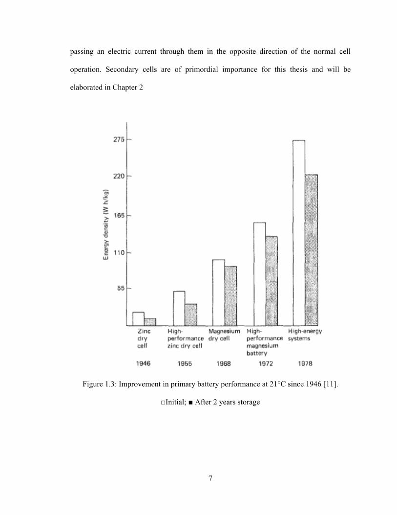
disposable battery. Until the 1970s, primary batteries were predominantly zinc-anode
based systems. Exponential performance improvements in terms of energy density, a
measure of the amount of energy stored in a given system or region of space per unit
volume (known as “Volumetric energy density” and expressed in W.h/m3), or per unit
mass (known as “Gravimetric energy density” and expressed in W.h/Kg), was undergone
since 1946 as shown in Figure 1.3.
More recently, low-temperature performance and storage capability were greatly
improved with the introduction of lithium-anode based systems and specialist couples
using anode materials such as cadmium, magnesium and indium-bismuth [11]. Energy
densities and corresponding operating temperature range for widely used primary
batteries in order of increasing gravimetric energy density are tabulated in Table 1.2.
High energy density is one of many parameters users must rely on in order to select
the most appropriate battery system for their specific application. Operating temperature
range, shelf life and on-load cell voltage are other crucial parameters that need to be
carefully considered as well.
Secondary cells, on the other hand, also known as rechargeable cells, storage cells or
accumulators, have the ability to be reconstituted into their original chemical form by
6
passing an electric current through them in the opposite direction of the normal cell
operation. Secondary cells are of primordial importance for this thesis and will be
elaborated in Chapter 2
Figure 1.3: Improvement in primary battery performance at 21°C since 1946 [11].
Initial; After 2 years storage
7
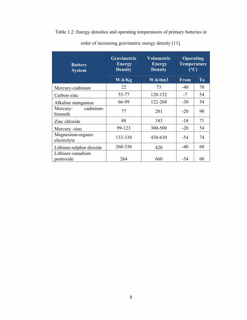
Table 1.2: Energy densities and operating temperatures of primary batteries in
order of increasing gravimetric energy density [11].
Gravimetric Energy Density
Volumetric Energy Density
Operating Temperature
(°C) Battery System
W.h/Kg W.h/dm3 From To 22 73 -40 70 Mercury-cadmium
55-77 120-152 -7 54 Carbon-zinc 66-99 122-268 -30 54 Alkaline manganese
Mercury- cadmium-bismuth 77 201 -20 90
88 183 -18 71 Zinc chloride 99-123 300-500 -20 54 Mercury -zinc
Magnesium-organic electrolyte 133-330 430-610 -54 74
260-330 420 -40 60 Lithium-sulphur dioxide Lithium-vanadium pentoxide 264 660 -54 60
8
CHAPTER 2
SECONDARY CELLS
2.1 Common Types of Secondary Cells
Secondary cells batteries are of particular interest to this thesis, specifically lead-acid
and lithium-ion (Li-Ion) batteries. Common types of rechargeable batteries are lead-acid,
nickel-cadmium (NiCd), nickel-metal-hydride (NiMH), lithium-ion (Li-Ion), lithium-ion-
polymer and reusable alkaline. The lead-acid battery was the pioneer in the rechargeable
battery market. It was invented in 1859 by the French physicist Gaston Planté. Until
today, the lead-acid battery remains the most widely used in automobiles, trucks, aircraft,
and other vehicles. The cell of a lead-acid battery hosts a negative electrode made of lead,
a positive electrode made of lead-dioxide and dilute solution of sulfuric acid. When a
load is connected across the main terminals of the battery, the negative lead electrode in
each cell dissociates into free electrons and positive lead ions. The electrons travel
through the external electric circuit and lead sulfate is formed by combining the positive
lead ions with the sulfate ions in the electrolyte [10].
When the electrons re-enter the cell at the positive electrode, they combine with the
lead dioxide and the hydrogen ions found in the electrolyte to form water and to release
additional lead ions that will in turn combine with the sulfate ions in the electrolyte to
form additional lead sulfate. As the sulfuric acid is gradually converted into water and the
electrodes are converted into lead sulfate, the lead-acid cell progressively runs down.
Charging the cell by reversing the current flow in its normal operation, the chemical
reactions described above are reversed and the cell is restored to its original chemical
condition. Today's readily available lead-acid batteries consist of three to six 2-Volts cells
9

connected in series. Lead-acid batteries are categorized as starting batteries or deep cycle
batteries. Starting batteries, like the ones used in automobiles, are designed to deliver
quick bursts of energy for a relatively short period of time. They sport a greater plate
count and their plates are generally thinner and have somewhat different material
composition. Deep cycle batteries on the other hand have less instant energy, but greater
long-term energy delivery. Deep cycle batteries have thicker plates and can survive a
number of discharge cycles [12].
Wet cell (also known as flooded), gel cell, and absorbed glass mat (AGM) are
classified as sub-categories and slightly different versions of the lead-acid battery.
The wet cell comes in two flavors: serviceable and maintenance free. The gel cell and the
absorbed glass mat batteries are specialty batteries that store charge very well and have
the ability not to sulfate or degrade as easily as wet cells. Absorbed glass mat batteries
are occasionally referred to as "sealed regulated valve", "dry cell", "non spillable", and
"valve regulated lead-acid" batteries. In general, the lead-acid battery system’s
advantages are low manufacturing costs, relatively high voltage per cell and good
capacity life. Its disadvantages on the other hand are that it is relatively heavy, it has poor
low-temperature characteristics and it cannot be left in the discharged state for too long
without being damaged [11].
Another widely used secondary cell, developed in the 1900's by American inventor
Thomas Edison is the alkaline cell, or nickel-iron battery. It operates very similarly to the
lead-acid cell except that the negative electrode is made of iron, the positive electrode is
made of nickel oxide, and the electrolyte consists of a solution of potassium hydroxide.
Producing about 1.15V per cell, rechargeable alkaline batteries are mainly used in heavy
10
industry applications and have a useful life of about ten years. Caution should be exerted
while recharging alkaline batteries due to highly flammable hydrogen gas emissions
given off during charging [10].
The nickel-cadmium cell or cadmium battery is an alkaline cell similar to the Edison
battery. It also produces about 1.15 V per cell, and its useful lifetime is about two and a
half times that of the Edison battery. As the names suggest, the main difference between
the nickel-iron battery and the nickel-cadmium battery is the fact that the iron electrode is
replaced by a cadmium electrode [10]. The cadmium battery was invented in 1899 by
Swedish scientist Waldmar Jungner . It was commercialized in Sweden in 1910 and
reached the United States in 1946 [2].
Some advantages of the nickel-cadmium battery include it being mechanically
rugged, offering excellent low temperature characteristics (operating/recharging),
tolerating deep discharges for long periods, tolerating more charge/discharge cycles than
most rechargeable batteries, boasting faster charge/discharge rates than lead-acid batteries
with minimal loss of capacity even at high discharge rates. The main disadvantages of the
nickel-cadmium battery include extreme toxicity, memory effect, and relatively low
energy density and high self-discharge [11].
Similar to the nickel-cadmium cell but offering thirty to forty percent higher capacity,
the nickel-metal-hydride cell appeared in the scene in the 1980's. Less prone to memory
effects and environmentally friendlier than nickel-cadmium, the nickel-metal-hydride
battery suffers however from limited service life, high self-discharge, performance
degradation under elevated temperature and relatively low storage lifetime [10].
11

For their size and weight, lithium-ion batteries pack very high energy density and can
hold a charge for much longer than conventional rechargeable lead-acid batteries. And
although the electrochemical potential of lithium-based power sources has been known
for quite some time, it was not until the 1960's that manufacturers were able to convert its
potential to practical cell hardware and demonstrate its benefits. In 1991, lithium-ion
batteries started to show up in the rechargeable battery market. Lithium is a lightweight,
chemically reactive metallic element with the ability to store large amounts of energy in
its atomic bonds [10]. Lithium ions migrate from a negatively charged carbon graphite
anode to a positively charged cathode, commonly made of cobalt oxide or lithium-iron-
phosphate. Lithium-ion batteries can be recharged hundreds of times but should not be
completely discharged before being recharged.
Manufacturers incorporate a small microprocessor into the lithium -ion battery pack
in order to manage it and to monitor the cells' temperature and state of charge of the
battery [10]. High temperatures will cause lithium-ion batteries to degrade and should be
avoided. Lithium-ion batteries only last a few years after manufacture before they
degrade and need to be replaced. Lithium-ion-polymer batteries technologically evolved
from lithium-ion batteries. The lithium-salt electrolyte, held in an organic solvent in the
lithium-ion design, is replaced by a solid polymer composite such as polyethylene-
oxide or polyacrylonitrile. Lithium-ion polymer batteries are cheaper to manufacture than
lithium-ion batteries and can withstand relatively heavier physical damage [11]. It is only
until 1996 that lithium-ion polymer batteries started appearing in consumer electronics.
The ranking in terms of on-load voltage of some of the most commonly used secondary
battery systems is tabulated in Table 2.1.
12

Table 2.1: On-load voltage (V) of some of the most commonly used secondary battery
systems [11].
From (V) To (V) Battery System 0.81 1.10 Silver-Cadmium 1.00 1.10 Silver-Hydrogen 1.00 1.25 Nickel-Cadmium 1.20 1.30 Nickel-Hydrogen 1.30 1.55 Silver-Zinc 1.50 1.65 Nickel-Zinc 1.50 2.00 Lead-acid
Table 2.2: Gravimetric energy density(W.H/Kg) of some of the most commonly used
secondary battery systems [11].
Gravimetric Energy Density
(W.h/Kg)
Battery System
Lead-acid 20 Nickel-Cadmium 35 Silver-Cadmium 53 Nickel-Zinc 56 Nickel-Hydrogen 62 Silver-Hydrogen 95 Silver-Zinc 113 Zinc-Chlorine 130 Zinc-Air 150 Sodium-Sulphur 240 Lithium-Chlorine 330 Lithium-Silver 370
13

The ranking in terms of gravimetric energy density of some of the most commonly
used secondary battery systems is tabulated in Table 2.2. The gravimetric energy density
of some of the most commonly used secondary batteries at a five hour discharge rate is
shown in an increasing order in Figure. 2.1. Last but not least, the basic parameters of
some of the most common secondary battery systems are tabulated in Table 2.3.
Figure 2.1: Gravimetric energy density of secondary batteries at a 5 hour discharge rate
[11].
14

Table 2.3: Basic parameters of secondary battery systems [11].
15

2.2 Reversible Charge/Discharge Property of Secondary Cells
Almost all rechargeable batteries operate under the same electrochemical principle: as
a cell is being discharged, a transfer of ions from one electrode to the other through the
electrolyte is fueled by the consumption of ions by one electrode and the generation of
ions by the other. On the other hand, when the cell is charged, the process is reversed
and the ions travel in the opposite direction. It is important to note that the overall
performance of the battery largely depends on the way the electrochemical process is
carried out.
2.3 Battery Charge/Discharge Performance Factors
The performance of a rechargeable battery can be heavily affected by the rate and
uniformity by which the ions move from one electrode to the other. This is because the
chemical reactions that occur at the electrodes are not instant and are limited by the ion
concentration on the electrodes respective surfaces. In turn, the concentration of ions
around the electrodes respective surfaces is dependent on the aptitude of the ions to travel
through the electrolyte and separator. The formation of dendrites, “outgrowths of material
from the electrodes", occurs when the ion concentration across the surface of an electrode
is uneven leading to a non-uniform chemical reaction rate [9]. Dendrites can eventually
outgrow themselves from one electrode to the other, shorting out the battery.
The metallic structure of the electrode can also drastically hinder the performance of
a rechargeable battery. The finer the grain structure, the lower the internal resistance and
the bigger the surface area. However, under extensive low current conditions, slower
chemical reactions lead to formation of metallic crystals. These crystals reduce the
surface area of the electrodes and therefore reduce the performance of the battery by
16

17
lowering its capacity and increasing its internal resistance which in turn will result in a
lower battery voltage during a fixed discharge current. Furthermore, when the internal
resistance of a battery increases, the charging process efficiency drops as unnecessary
heat generation arise [9].
CHAPTER 3
BATTERY CHARGING TECHNIQUES
3.1 Introduction
Battery charging techniques can be divided into three categories: conventional
charging techniques, pulse charging techniques and state of the art charging techniques.
Each category and its corresponding subcategories will be discussed separately.
3.2 Conventional Charging Techniques
3.2.1 Constant Current Trickle (CCT) Charging Technique
Conventional charging starts with the constant current trickle charge technique where
a battery is submitted to a very low constant current until it is fully charged. Constant
current trickle chargers are relatively simple and inexpensive to design. They are not
considered as technologically advanced chargers and they rely completely on the user to
start and terminate the charge [9]. Some constant current trickle chargers are specific to
certain rechargeable battery types. Others have the capability of adapting to different
rechargeable battery types by allowing the user to modify the charging profile. Feedback
based on crucial battery parameters is non-existent. Therefore, they run the risks of
damaging the battery due to overcharge and potential dendrite outgrowth.
3.2.2 Fast Constant Current (FCC) Charging Technique
The next step up is the fast constant current charge technique where a battery receives
a large current until it is fully charged. This concept can reduce the battery charging time
from ten hours under constant current trickle charge to three hours in fast constant current
charge. However, additional charge control and monitoring circuitry must be embedded
into the charger in order to terminate the charge once the battery is full and in order to
18

monitor the battery temperature while it is being charged. While dramatically reducing
the charge time, the fast constant current charging technique does not take into account
the internal electrochemical process of the battery being charged resulting in significant
negative long-term effects [9]. Dendrites growth, large metallic crystal formation and
increased internal resistance caused by the large constant charging current lead to reduced
battery capacity and shortened life cycle.
3.2.3 Constant Current Constant Voltage (CCCV) Charging Technique
A slight improved fast constant current charge technique is known as the constant
current constant voltage charging technique where a battery receives a constant current
until it reaches a predetermined voltage value at which point the charging voltage is held
constant until the charging current drops to a near zero value. The constant current
constant voltage charging technique produces the same negative long-term effects as of
the fast constant current charging technique but to a lesser degree [9].
In short, conventional charging techniques are simple, low cost solutions, aimed at
recharging secondary batteries without taking into account eventual long term negative
effects such as battery capacity reduction and shortened life span.
3.3 Pulse Charging (PC) Technique
It was not until the 1970's that the pulse charging concept entered the commercial
rechargeable battery market [9]. The pulse charging concept derived from taking into
account the fact that an extended constant current charge leads to an ion concentration
gradient build up on the ion-generating electrode due to the mass transport limitations
within the battery. And as previously mentioned, this leads to dendrites outgrowth,
metallic crystal formation and an increase in the internal resistance of the battery which
19

20
in turn leads to heat generation, poor battery charge efficiency, poorer battery capacity
and shorter battery lifespan.
However, by periodically interrupting the charge for a relatively short period of time,
ions are able to diffuse and distribute more evenly throughout the battery, minimizing the
negative effects mentioned above. The original pulse charging technique relied on
supplying a charging pulse current for about a full second followed by a resting period in
the order of milliseconds. This charge/rest period was carried on repeatedly until the
battery was fully charged. In the late 1970's, the pulse charging technique evolved into a
four step charge/rest/discharge/rest period. The introduced discharge impulse was very
short in duration and had two and a half times the magnitude of the charging pulse. The
newly introduced discharging impulse accounted for even faster ion redistribution
throughout the battery which improved the battery charging efficiency and the overall
battery performance.
3.4 State of The Art Charging Technique
State of the art battery charging emerged in the early 1990's. It got more and more
involved in taking into account the electrochemical properties of rechargeable batteries in
order to offer better charging algorithms to charge the batteries faster, more efficiently
while still paying extra attention to maximize the battery's capacity and the battery's
lifespan. For instance, Podrazhansky [9] discovered that applying multiple shorter
discharging pulses with much greater amplitude benefited all secondary battery types.

CHAPTER 4
FAST CHARGING TECHNIQUES EVALUATION
4.1 Introduction
This chapter thoroughly evaluates patented fast charging techniques and apparatus
ranging from 1971 to 2002. The evaluation is carried out in order to determine how
contemporary chargers make use of today’s available knowledge as it relates to
efficiently charging secondary batteries. Several criteria leading to a safe and accountable
charge are to be probed.
4.2 Control Circuitry for Termination of Rapid Battery Charging
In 1971, inventor Indar K. Sethi patented a method and apparatus for recharging any
type of secondary battery irrespectively of its internal impedance [13]. Sethi’s hand
drawn circuit shown in Figure 4.1 is claimed to rapidly recharge any and all types of
secondary batteries irrespectively of their internal impedance via a Pulse Charging
Technique consisting of a controlled charging current pulse followed by a discharging
pulse that occurs in function of the battery’s terminal voltage. A careful circuit analysis
seconds that the technique used to generate the pulse charges is contingent on the
frequency of the input voltage of the circuit. Moreover, the pulse discharging is
dependent on the battery’s terminal voltage and is forced to increase with the battery’s
terminal voltage. Sethi designed a smart apparatus fully capable of rapidly recharging
secondary batteries. However, his design bears a heavy set of drawbacks.
21

Figure 4.1: Control Circuitry for Termination of Rapid Battery Charging [13].
First and foremost, the pulse charging/discharging originating from Sethi’s patented
circuit occurs due to layout of its components. Therefore, while inheriting some of the
benefits of pulse charging, Sethi’s fast charging algorithm is still not specific to the
internal chemistry of the battery being recharged. The only feedback received from the
battery being recharged is limited to the voltage across its terminals. Moreover, Sethi’s
circuit relies on user intervention for manually setting the charging current magnitude
based on battery characteristics supplied by the battery’s manufacturer. Therefore, the
end-user operating on Sethi’s circuit must possess a good working knowledge of the
apparatus and of rechargeable batteries In general. This makes the entire process of
recharging a specific battery user dependent and error prone. Furthermore, Sethi’s circuit
does not account for possible battery overheating or gas generation which could
potentially damage the battery and/or hurt the end-user. Last but not least, Sethi’s design
22
does not calculate of disclose the state of charge of the battery being recharged at any
point in time.
4.3 Method and Apparatus for Rapid Battery Charging
In 1979, inventor Per-Edward Samsioe, unsatisfied with the long charging period
recommended by battery manufacturers of secondary batteries, claims that a secondary
battery can be charged to eighty percent (80%) of its capacity by a constant current in less
than an hour as long as the charging current can be interrupted if the battery experiences
high temperature or gas development [14]. Moreover, Samsioe adds that all
contemporary charging methods, except for the constant current charging method, rely
heavily on battery parameters and are therefore not sufficiently safe. For the reasons
mentioned above, Samsioe patented a method and apparatus that can rapidly charge a
secondary battery without depending on its parameters. Samsioe’s hand drawn patented
charging circuit is shown in Figure 4.2
Samsioe’s claim which states that a secondary battery can be charged to eighty
percent (80%) of its capacity by a constant current in less than an hour as long as the
charging current can be interrupted if the battery experiences a high temperature or gas
development is supported by the fact that the charge acceptance (willingness of a battery
to accept and retain charge) of a secondary battery is much higher when the battery gets
closer to being depleted. An empty battery has the ability to accept and retain much more
charge than a battery that is closer to being fully charged. Therefore, Samsioe’s patented
charging circuitry begins its cycle by discharging the battery that needs to be recharged
through a resistor before actually recharging it.
23
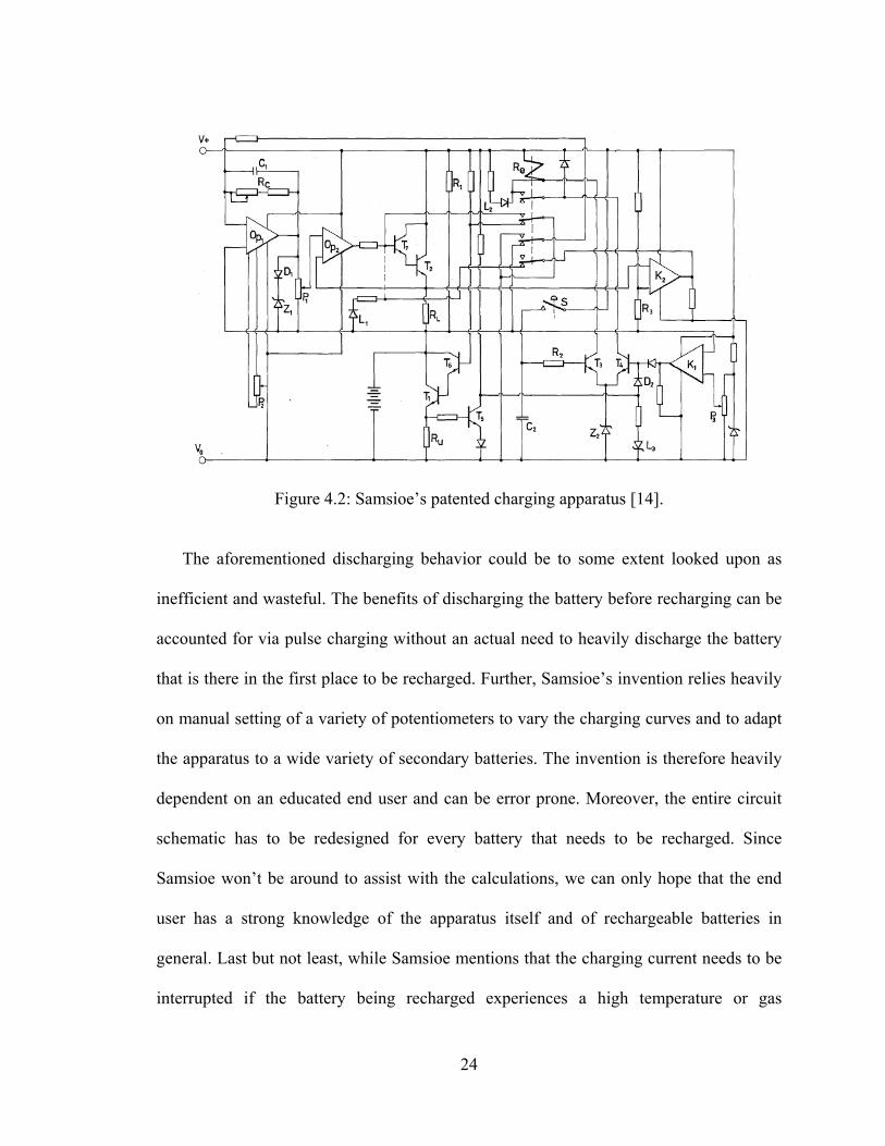
Figure 4.2: Samsioe’s patented charging apparatus [14].
The aforementioned discharging behavior could be to some extent looked upon as
inefficient and wasteful. The benefits of discharging the battery before recharging can be
accounted for via pulse charging without an actual need to heavily discharge the battery
that is there in the first place to be recharged. Further, Samsioe’s invention relies heavily
on manual setting of a variety of potentiometers to vary the charging curves and to adapt
the apparatus to a wide variety of secondary batteries. The invention is therefore heavily
dependent on an educated end user and can be error prone. Moreover, the entire circuit
schematic has to be redesigned for every battery that needs to be recharged. Since
Samsioe won’t be around to assist with the calculations, we can only hope that the end
user has a strong knowledge of the apparatus itself and of rechargeable batteries in
general. Last but not least, while Samsioe mentions that the charging current needs to be
interrupted if the battery being recharged experiences a high temperature or gas
24

development, his patented charging circuit does not exhibit a current interrupting
mechanism that interacts with safety sensors, such as temperature and gas sensors.
4.4 Method and Apparatus for Rapidly Charging and Reconditioning a Battery
In 1999, inventors Pittman et al. patented a charging method and apparatus designed
to quickly and efficiently charge secondary batteries while simultaneously reconditioning
them [15]. Unsatisfied with prior art battery chargers associated with long charging times,
inefficient charging, and steady decrease in charge acceptance and in life cycles, Pittman
et al. built a quick and efficient charger based on the pulse charging technique. Pittman et
al. charging circuit is shown in Figure 4.3.
Observing that constant current chargers can easily damage a secondary battery by
overestimating the constant charge current which can eventually completely destroy a
functional battery, and that pulse chargers that try to deliver bursts of energy to
rechargeable batteries through pulses usually operate at a high charging voltage which
gets the job done quicker at the expense of gradually destroying the battery through heat
generation and electrolyte evaporation, Pittman et al. decided to go with a pulse charging
algorithm containing a periodic combination of charging pulses, discharging pulses and
recovery periods in order to greatly improve some limiting factors of charge acceptance
of secondary batteries. The discharge/charge/stabilize periodic waveform is shown in
Figure 4.4.
25

Figure 4.3: Pittman et al.'s patented charging circuit [15].
Pittman et al. were successful at designing an advanced state of the art microprocessor
driven charging algorithm minimizing long term negative effects associated with
conventional charging techniques.
Figure 4.4: Discharge/charge/stabilize periodic waveform used to charge secondary [15].
26

The charging sequence insists on applying a discharge pulse immediately before the
charging pulse in order to minimize the internal impedance of the rechargeable battery
and therefore efficiently utilize a lower recharge voltage leading to lower energy wasted
in heat and better charge acceptance.
Different charging “profiles” are applied to different battery chemistries in order to
optimally recharge them. However, the charging profiles are based on timing data
experimentally determined which might not do justice to batteries with different
capacities. Furthermore, the fact that the discharge/charge/rest sequence is predetermined
affirms that the charging algorithm is not constantly polling the rechargeable battery on
hand to optimize the charging based on its internal chemistry. State of charge
determination and temperature monitoring of the battery being recharged are referred to
as “features” in this patent. In reality these parameters should be constantly polled to
provide crucial feedback to the microcontroller in order for it to adjust and modify the
charging waveform on the fly.
4.5 Rapid Charging of a Battery by Applying Alternating Pulsed Large Current without a
High Temperature
In 2000, inventor James Chin-Ming Chen driven by the belief that there is a need for
“simple” and “practical” rapid battery charging that that does not rely on high precision
and expensive measuring circuitry so that rapid battery charging can be achieved on a
daily basis at a low cost, conceived a charging method to satisfy that need [16].
Chen’s charging method is a simple application of a pulse charging technique to achieve
a fast battery charge while avoiding battery overheating and potential overcharge. Chen’s
charge current diagram is shown in Figure 4.5. It is important to note that Chen’s
27
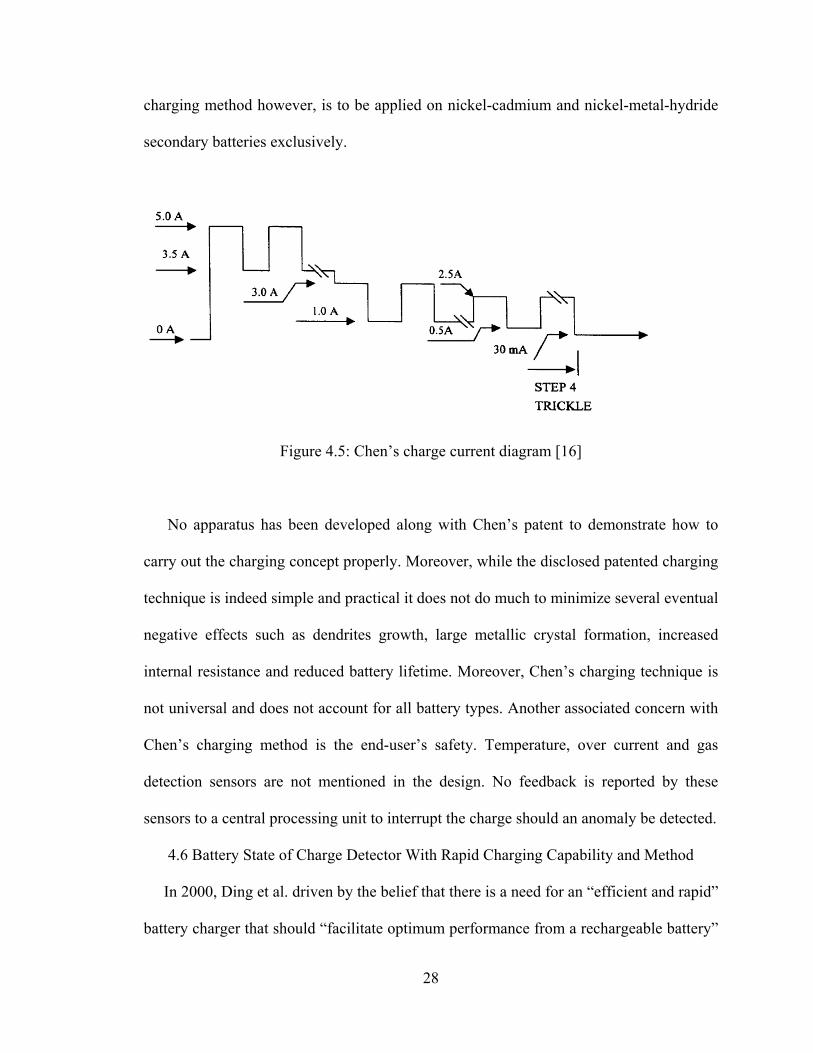
charging method however, is to be applied on nickel-cadmium and nickel-metal-hydride
secondary batteries exclusively.
Figure 4.5: Chen’s charge current diagram [16]
No apparatus has been developed along with Chen’s patent to demonstrate how to
carry out the charging concept properly. Moreover, while the disclosed patented charging
technique is indeed simple and practical it does not do much to minimize several eventual
negative effects such as dendrites growth, large metallic crystal formation, increased
internal resistance and reduced battery lifetime. Moreover, Chen’s charging technique is
not universal and does not account for all battery types. Another associated concern with
Chen’s charging method is the end-user’s safety. Temperature, over current and gas
detection sensors are not mentioned in the design. No feedback is reported by these
sensors to a central processing unit to interrupt the charge should an anomaly be detected.
4.6 Battery State of Charge Detector With Rapid Charging Capability and Method
In 2000, Ding et al. driven by the belief that there is a need for an “efficient and rapid”
battery charger that should “facilitate optimum performance from a rechargeable battery”
28

patented an advanced electronic design that polls a rechargeable battery at regular
intervals to determine its state of charge [17]. Several factors account for the calculated
estimation of the state of charge, namely the battery’s temperature, pressure, internal
impedance and corresponding phase angle. Once the state of charge is calculated then the
battery gets recharged according to a preset pulse charging pattern, consisting of positive
pulses, negative pulses, or a combination of both, recorded on a lookup table specifically
for the contemporary determined state of charge value. The block diagram of Ding et al.’s
patented invention is shown in Figure 4.6.
While the Ding et al.’s patented invention follows a correct logic, the implementation
of a corresponding apparatus can be quite daunting. For example, and in order for the
charger to be universal, an exhaustive list of secondary batteries of all types, sizes and
ratings need to be pretested in a lab to determine an accurate and ever increasing look-up
table. it is important to notice that different lookup tables per rechargeable battery need to
be established at different operating conditions, such as different room temperatures and
different room pressures which will exponentially increase the total number of lookup
tables to be predetermined in the first place.
29

Figure 4.6: Block diagram of Ding et al.’s patented invention [17].
Moreover, in order to determine the battery’s internal impedance and electrochemical
overvoltage, Ding et al. refer to employing approximation techniques that might not be
accurate. Electrochemical Impedance Spectroscopy (EIS) in general, a method aimed at
measuring the internal impedance of a device by sending an alternating current and
measuring its response at different frequencies relies on three different variables, namely
temperature, state of charge and DC-current which are not elaborated in this paper.
Ding et al.’s patented invention seems easier said than done. While the logic that the
invention relies on is theoretically solid, concretizing such an invention is no easy task,
and by no means did Ding et al. pin down all the problems that will arise from
concretizing such a charger.
30

4.7 Rapid Battery Charging Method and Apparatus
In 2002, Vladimir Petrovic, fueled by the belief that there is a specific need for rapid
battery chargers that can quickly recharge lead-acid batteries without reducing their
service life patented an invention capable of recharging lead-acid batteries in under two
hours [18]. A block diagram of Vladimir Petrovic’s invention is shown in Figure 4.7.
Figure 4.7: Block diagram of Vladimir Petrovic’s patented invention [18].
The disclosed charging method is a special case of pulse charging techniques. A
periodic charge/rest/discharge/rest charging waveform is applied for two hours until the
battery (hopefully) reaches its full charge. Vladimir Petrovic clearly states that his
invention relies on the described specific charging waveform because he found that this
charging cycle has “unexpectedly beneficial effects in that, in comparison to standard
31
charging cycles, it reduces the time taken to bring a battery to full charge and increases
the total charge that can be delivered to the battery.”
The benefits of pulse charging techniques were common knowledge in 2002. While
functional, Vladimir Petrovic’s patented design seemed passé before it was even
conceived. The fact that the end-user has to perform manual calculations and manually
adjust different potentiometers instead of relying on precise microcontrollers makes the
entire design error prone and user dependent. Furthermore, the entire idea of discharging
a battery through a power resistor until it reaches a reference voltage before recharging it
sounds inefficient and wasteful. Moreover, Vladimir Petrovic failed to mention that
different batteries would need different power resistor combinations in order to maintain
a constant safe discharge value since no temperature, gas generation or over-current
sensors are part of his patented design.
32

CHAPTER 5
SECONDARY BATTERY MODELING TECHNIQUES
5.1 Electrical Battery Model for Use in Dynamic Electric Vehicle Simulations
Kroeze et al.’s paper focuses on developing an electrical battery model for use in
dynamic electric vehicle simulations [19]. The main requirements of the battery model
are its capability to simulate at any given time the actual state of charge, I-V
characteristics and dynamic behavior of a lead-acid, lithium-ion or nickel-metal-hydride
battery. Kroeze et al.’s proposed battery model is shown in Figure 5.1
Researching readily available electrochemical, mathematical and electrical models of
lead-acid, lithium-ion and nickel-metal-hydride batteries, Kroeze et al. decided to leave
behind electrochemical models due to their lack of parameters and mathematical models
due to their inaccuracy and lack of relation between model parameters and I-V
characteristics. Therefore, Kroeze et al. opted for a combination of well known electrical
models, mainly the Thevenin model and the Runtime-based electrical model in order to
take advantage of their respective positive attributes. This combination resulted in a
model capable of predicting the state of charge, terminal voltage and power losses of
lead-acid, lithium-ion and nickel-metal-hydride batteries.
Nevertheless, in order to simulate a specific rechargeable battery, one must first
collect a large set of data using an apparatus consisting of data loggers, an electronic
load, a power supply, special computer capture software and other equipment. The data
collected undergoes a time consuming analysis that calculates and interpolates values that
are finally tabulated for future use.
33

Figure 5.1: Proposed electrical battery model [19].
The aforementioned look-up table is then used by a modeling program to determine
open circuit voltages at specific states of charge of the battery being simulated. Kroeze et
al. managed to conceive a battery model that successfully simulates a lead-acid, lithium-
ion or nickel-metal-hydride battery within their needs. Nevertheless, the model still lacks
accounting for variations in ambient temperature, the battery’s self-discharge and it’s
cycling degradation which could substantially alter the final result.
5.2 An Enhanced Dynamic Battery Model of Lead-acid Batteries using Manufacturers'
Data
Medora et al.’s paper covers an enhanced dynamic battery model of lead-acid
battery, namely the Yuasa DM55-12, 12V, 57-Ah, using the manufacturer’s data sheet
parameters and some selected handbook curves [20]. The model is then used in
conjunction with a Pulse Width Modulator (PWM) model and a DC motor model to
simulate a transportation system and to analyze the effect of adding ultra-capacitors to
minimize the battery’s current peak requirements. Medora et al.'s dynamic battery model
with charge/discharge characteristics is shown in Figure 5.2. Medora et al.’s main
objective is to derive a “not too complex” battery model capable of simulating a Yuasa
34
DM55-12, 12V, 57-Ah lead-acid battery’s terminal voltage and internal resistance in
function of the battery’s state of charge and internal capacity at any given time. In order
to successfully develop their model, Medora et al. relied on the Yuasa DM55-12, 12V,
57-Ah lead-acid battery’s manufacturer data sheet along with a combination of “algebraic
equations” that define the battery’s capacity as a function of discharge current, the
discharge voltage and the battery’s internal resistance as a function of state of charge and
finally variable multipliers for adjusting model parameters at increasing discharge
current.
While Medora et al. might have been able to maneuver a quite specific lead-acid
battery model to meet their simulation needs they avoided to deal with real constraints
such as battery aging and battery temperature effects that could substantially alter the
battery’s model behavior during simulation. Moreover, by avoiding to detail the process
of embedding the manufacturer’s data into the simulation model as well as properly
deriving the algebraic equations to come up with a correct model, Medora et al. do not
give the audience a chance to build upon their work to come out with their own specific
simulation models.
Last but not least, the mandatory use of Analog Behavioral Modeling (ABM)
techniques to simulate the rechargeable battery which results in relatively shorter
simulation times and less accurate results does not offer the audience a choice of
selecting accuracy versus speed.
35

Figure 5.2: Medora et al.’s battery model with charge/discharge characteristics [20].
5.3 Design of Interface Circuits with Electrical Battery Models
Kim et al.’s paper presents three different types of lead--acid battery models, namely
the ideal battery model, the linear battery model and the Thevenin battery model shown
in Figure 5.3, to be simulated in conjunction with converters and motors models [21].
Kim et al realize that in order to obtain valid simulation results, they need to account for
the battery’s internal characteristics. The first battery model discussed is the ideal model,
represented by a single ideal voltage source. While very simple, this model does not
36
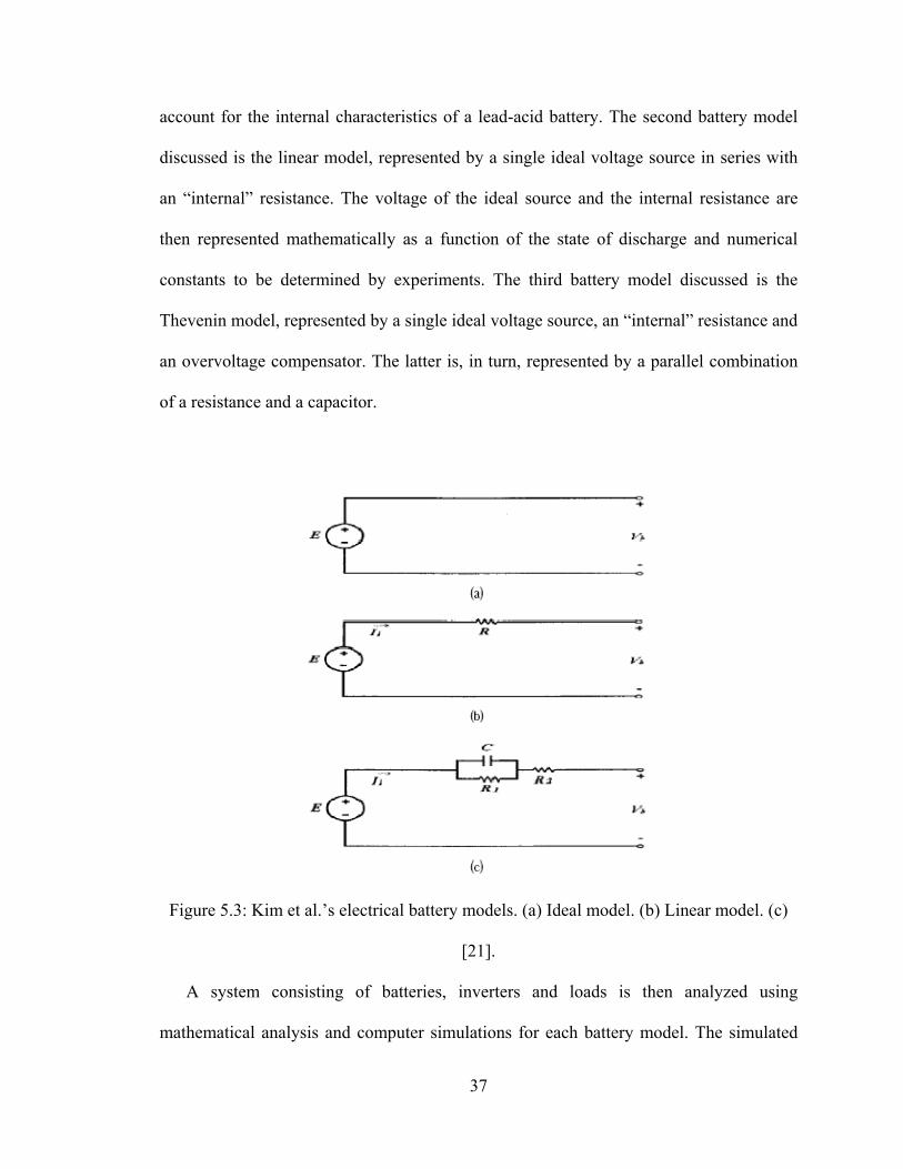
account for the internal characteristics of a lead-acid battery. The second battery model
discussed is the linear model, represented by a single ideal voltage source in series with
an “internal” resistance. The voltage of the ideal source and the internal resistance are
then represented mathematically as a function of the state of discharge and numerical
constants to be determined by experiments. The third battery model discussed is the
Thevenin model, represented by a single ideal voltage source, an “internal” resistance and
an overvoltage compensator. The latter is, in turn, represented by a parallel combination
of a resistance and a capacitor.
Figure 5.3: Kim et al.’s electrical battery models. (a) Ideal model. (b) Linear model. (c)
[21].
A system consisting of batteries, inverters and loads is then analyzed using
mathematical analysis and computer simulations for each battery model. The simulated
37

results confirm that using a Thevenin model of the lead-acid battery (that accounts for the
battery’s internal characteristics) will provide the most accurate results while designing a
condenser filter. However, using the less complicated linear model will still generate
acceptable results. It is no secret that accounting for a battery’s internal characteristics
during simulation will provide results closer to reality. The models presented however
account for so little of a real lead-acid battery’s internal characteristics that they should
only be used in certain specific situations such as the one used in Kim et al.’s paper’s
scenario.
5.4 A Battery Model Including Hysteresis for State-Of-Charge Estimation in Ni-Mh
Battery
Xuyun et al.’s paper presents a powerful nickel-metal-hydride battery model suitable
for various simulation-based designs [22]. The model accounts for the hysteresis
phenomenon that directly affects the state of charge determination of the battery in
question. Xuyun et al.’s equivalent circuit model for the Ni-MH battery is shown in
Figure 5.4. Electrochemical Impedance Spectroscopy (EIS) is first used to determine the
impedance spectra of a nickel-metal-hydride battery. A basic equivalent circuit of the
nickel-metal-hydride battery is then determined.
Open circuit values of an nickel-metal-hydride battery were then measured under
different States of charge for a charging battery and then for a discharging battery. An
updated equivalent circuit model based on the electrochemical impedance spectroscopy
results and the hysteresis measured results is then presented. Calling on external
references, state space equations for the specific nickel-metal-hydride model are then
derived and the Kalman Filter method is applied to better estimate the state of charge.
38

Figure 5.4: Xuyun et al.’s equivalent circuit model for the Ni-MH battery [22].
Last but not least, the model’s simulated results are compared to an evaluation model
and are shown to come very close to each other. It is important to note that the nickel-
metal-hydride model derived herein is based on a large number of assumptions. First and
foremost, electrochemical impedance spectroscopy relies on three different variables,
namely temperature, state of charge and DC-current. Xuyun et al.’s results used to derive
the first equivalent circuit of the model are based on one specific scenario where the
temperature is constant and no dc-current is applied. Therefore, two out of the three
variables necessary to yield to accurate results while using electrochemical impedance
spectroscopy have been ignored. Furthermore, the hysteresis phenomenon data used to
derive the second equivalent circuit of the model are based on one specific nickel-metal-
hydride battery constituted of five single cells in series. Next, Xuyun et al. clearly specify
that an inductive element for the equivalent circuit has been omitted since “nickel-metal-
hydride batteries are less used at so high frequency”. Further investigation of an omitted
39

40
“non-linear resistor” is also needed. While a functional nickel-metal-hydride battery
model is presented in this paper, it can only be used in very specific situations to estimate
the state of charge under specific conditions limited by the assumptions made to develop
the model. In particular, effects of temperature, aging and charging/discharging methods
used are not accounted for.

CHAPTER 6
CONCLUSION AND FUTURE DIRECTIONS
6.1 As it Relates to Fast Charging Techniques
Several fast charging techniques were reviewed in this paper, the most advanced and
efficient one being the state of the art charging technique. Nevertheless, less
advantageous charging techniques are still being widely used on a daily basis due to their
easy implementation and low design cost. These less advantageous charging techniques
burn more power per charge and shorten the service life of the battery being charged.
They are in a way detrimental to the battery being recharged.
If they must coexist, less advantageous inexpensive charging techniques and
corresponding chargers should at least be mandated to improve their energy conversion
mechanism in terms of efficiency, defined as the ratio of output power over input power.
Most electronic appliance wall chargers for instance, are quite inefficient and consume
power while in standby. There is a need for a unified standard to enforce such chargers
to reduce to a bare minimum their consumption of standby power and to maintain higher
conversion efficiencies. Moreover, a large amount of today’s battery chargers still
discharge rechargeable batteries to a predetermined value before recharging them. The
discharge is usually carried out through power resistors that convert all of the energy to
wasted heat. Therefore, there is a need for a highly efficient storage mechanism that
could potentially store the aforementioned wasted energy for better future use.
Contemporary state of the art battery charging and corresponding chargers however
are not perfect either. There is a lot of room for improvement. Today’s most advanced
chargers still find it challenging to automatically detect the battery’s internal chemistry in
41
order to optimize the charging. With a little more consideration from battery
manufacturers or battery distributors, a small scannable tag strategically placed on the
rechargeable battery itself could potentially address this issue and provide ample
information to the battery charger in order to smartly and efficiently optimize the charge.
Further, we hope to see in the near future a medley of inexpensive yet accurate and
low power sensors and microcontrollers embedded into the battery itself. These sensors
would provide at any given time the critical internal characteristic of the battery being
recharged, such as temperature, gas generation and electrochemical state. All of the data
and information collected from the battery would be immediately transferred wirelessly
or through a standard exchange protocol to the charger. The latter’s central processing
unit (CPU) will in turn use the fetched data from the various sensors to calculate on the
fly internal parameters of the battery such as state of charge and Depth of Charge and
adjust accordingly the charging waveform to deliver the fastest, safest and most efficient
charge.
6.2 As It Relates to Battery Modeling for Fast Charging Simulations
Various battery models have been developed to date to mimic the behavior of
rechargeable batteries. However, most of these models were conceived to complete
specific electric vehicles (EV) and hybrid electric vehicles (HEV) simulations. Therefore,
the reviewed models are based on numerous assumptions and do not account for the
important effects of temperature, aging, remaining useful life, self discharge and for
effects arising from the methods used to charge the battery in the first place, such as
memory effect, decreased capacity, increased internal resistance, etc… Therefore, the
reviewed models would not be of much help for the scope of this thesis.
42

The MathWorks, Inc., a leading global provider of software for technical computing
and model-based design, creator of the famous Matlab and Simulink suites, recently
introduced through their SimPower Systems add-on, a rechargeable battery model
capable of simulating the charge and discharge of several different types of popular
secondary battery chemistries, namely lead-acid, lithium-Ion, nickel-cadmium and
nickel-metal-hydride. The block model and its equivalent block diagram circuit are
shown in Figure 6.1. In its simplest form, the battery model is represented by a controlled
voltage source that represents the rechargeable battery’s open circuit voltage in series
with a resistor that represents the internal resistance of the rechargeable battery.
The latter’s current feedback, whether under charge or discharge mode of operation,
undergoes integration over time, to account for extracted capacity, low pass filtering, to
account for low frequency current dynamics and Laplace transform to account for
exponential zone dynamics. The aforementioned calculated data then dictates the value of
the controlled voltage source.
The parameterized respective discharge functions of the different rechargeable battery
chemistries are tabulated in Table 6.1. Moreover, the parameterized respective charge
functions of the different rechargeable battery chemistries are tabulated in Table 6.2.
Finally a brief description of each parameter is tabulated in Table 6.3.
While being one of the most advanced rechargeable battery model to date, SimPower
Systems’ model exhibits some serious drawbacks. For one, the model doesn’t account for
memory effects, self-discharge effects, aging effects and previous charge/discharge
history in order to derive remaining useful life. Moreover, the internal resistance of the
battery is considered constant during the charge and the discharge cycles and doesn't vary
43

with the amplitude of the current. Furthermore, the capacity of the battery doesn't change
with the amplitude of current. However, in 1897 German scientist W. Peukert presented a
law stating that the capacity of a lead-acid battery varied with the rate at which the
battery was being discharged.
Figure 6.1: SimPower Systems' library battery block (Left) and equivalent circuit (Right).
[23]
Peukert demonstrated that as the rate of discharge increased, the battery's available
capacity decreased. Therefore the battery model does not account for the Peukert effect.
Last but not least, the presented model doesn’t take into account the battery’s internal
cells temperature.
44

Table 6.1: Parameterized respective discharge functions of different rechargeable battery
chemistries [23].
Table 6.2: Parameterized respective charge functions of different rechargeable battery
chemistries [23].
45

Table 6.3: Brief description of the functions’ parameters [23].
PARAMETER DESCRIPTION UNITS
EBatt Nonlinear Voltage Volts (V)
E0 Constant Voltage Volts (V)
Exp(s) Exponential Zone Dynamics Volts (V)
Sel(s) Represents the Battery Mode of Operation(1 for charge, 0 for discharge)
N/A
K Polarization Constant or Polarization Resistance Ampere per hour(Ah-1) or Ohms (Ω)
i* Low Frequency Current Dynamics Amps (A)
i Battery Current Amps (A)
it Extracted Capacity Ampere Hour (Ah)
Q Maximum Battery Capacity Ampere Hour (Ah)
A Exponential Voltage Volts (V)
B Exponential Capacity Per Ampere Hour (Ah)-1
Not taking temperature into account can be quite dangerous, especially as it relates to
fast charging techniques. As frequently emphasized in this thesis, the process of fast
charging relies on running a large current into the battery to reduce charge time.
Depending on the method of delivery, a high current can engender a high temperature
increase. If not dissipated properly, the heat generated could permanently damage the
rechargeable battery. Understanding heating effects in batteries is of primordial
importance in order to account for it. There are four main types of heating effects that
46

occur within a battery. The first one is referred to as “Ohmic heating effects” due to Joule
heating effects related to operating current and the electrical internal resistance and
external contacts resistance of the battery itself.
The Ohmic heating value expressed in calories can be determined by using the
following equation: .
where I2Total represents the squared value of
the current flowing through or from the battery, RTotal represents the combined resistance
of the battery’s internal impedance and the battery’s contact terminals, and seconds is the
duration in seconds. Note that the Ohmic heating value “J” is expressed in calories (Cal).
The second heating effect is known as the “chemical heating effect” due to the heat
generated or absorbed by the chemical reaction. Lead-acid batteries engender an
exothermic reaction during discharge. However while charging at low current, Lead-acid
batteries tend to absorb heat through their endothermic reaction. The “chemical heating
effect” is identified with the content change of the reaction, denoted by “ΔH” which is
given by the following equation: ∆. .
where ∆ is the heat change accompanying the cell reaction, n is the number of
equivalents of chemical reaction, F is one Faraday or 96,500 Coulombs, E is the
electromotive force the cell, T is the temperature in Kelvin, is the temperature
coefficient of the electromotive force at constant pressure and C is the capacity of the
battery in Ampere-Hours. The content change of the reaction ∆ , is expressed in Calories
(Cal).
The third heating effect encompasses to localized heating effects due to the tracking
of current along the low-conductivity paths on the top of the battery. Finally the fourth
47
heating effect represents the chemical heating effect due to the dissociation of water to
hydrogen and oxygen towards the end of the charge. This type of effect applies only to
certain batteries, such as Lead-acid batteries, and occurs to an appreciable extent only
when batteries are getting overcharged.
With a better understanding of heating effects associated with recharging or
discharging a secondary battery an educated user can tackle battery modeling and
simulation differently. For instance, a simulation of a lead-acid battery discharging at
different rates through a random load is performed. For simulation purposes, the model is
assumed to be a lead-acid battery with the respective parameters tabulated in Table 6.4.
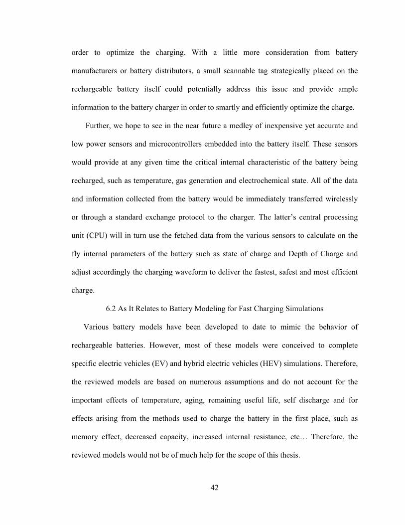
The simulated discharge curves of the aforementioned model for different discharging
rates namely, 50 (A), 100 (A), 150 (A), 200 (A), 400 (A) and 800 (A) are shown in
Figure 6.2. More importantly the simulation over a sixty seconds period of the battery
being discharged through a random load is shown in Figure 6.3 which is divided into
three scope captures. The first scope capture shows the state of charge in yellow of the
lead-acid battery decreasing over time from 100% to about 84%.
The second scope capture represents the lead-acid battery's voltage in blue
decreasing over time from about 12.5 (V) to about 8.5 (V). Last but not least, the third
scope capture depicts the lead-acid battery's discharging current in magenta over time
ranging from about 50 (A) up to 690 (A). With the aforementioned data readily available
from the simulation software, the Ohmic heating "J" and the content change of the
reaction, “ΔH” can be calculated.
48

Table 6.4: Simulated lead-acid battery model parameters
PARAMETER DESCRIPTION VALUE UNITS
Nominal Voltage 12 Volts (V)
Rated Capacity 30 Ampere Hour (Ah)
Initial State of Charge (SOC) 100 Percentage (%)
Maximum Capacity 31.25 Ampere Hour (Ah)
Fully Charged Voltage 13.0658 Volts (V)
Nominal Discharge Current 6 Amps (A)
Internal Resistance 0.004 Ohms (Ω)
Capacity at Nominal Voltage 9.3083 Ampere Hour (Ah)
Exponential Zone Voltage 12.2171 Volts (V)
Exponential Zone Capacity 0.1 Ampere Hour (Ah)
49
Figure 6.2: Simulated discharge curves of the modeled Lead-acid Battery at different
discharge rates.
In order to calculate the Ohmic heating "J" versus time, raw data was exported to
excel. The data was then manipulated and resulted in Figure 6.4 that displays the Ohmic
heating versus time. Similarly, the chemical heating effect "ΔH" versus time is illustrated
in Figure 6.5. Finally the combined heating effects "J+ΔH" versus time is displayed in
Figure 6.6.
50

Figure 6.3: Simulation results of the lead-acid battery being discharged.
51

0.00E+00
1.00E+01
2.00E+01
3.00E+01
4.00E+01
5.00E+01
4.58
E‐20
0.95 2.9
5.4
7.9
10.4
13.1
15.6
18.1
20.6
22.7 25
27.5 30
32.7 35
37.1
39.6
42.1
44.5
46.7
49.2
51.7
54.4
56.8
59.4
Ohmic Heating(Cal)
Simulation Time Progress (s)
Ohmic Heating Versus Time
Figure 6.4: Ohmic heating versus time.
0.00E+00
2.00E+01
4.00E+01
6.00E+01
8.00E+01
1.00E+02
1.20E+02
4.58
E‐20
0.95 3.1
5.7
8.3
10.9
13.7
16.3
18.9
21.5
23.7
26.1
28.7
31.3
34.1
35.9
38.5
41.1
43.6
45.9
48.5
51.1
53.9
56.7
59.1
Chemical Heating (cal)
Time (s)
Chemical Heating Effect Versus Time
Figure 6.5: Chemical heating effect versus time.
52

0.00E+00
2.00E+01
4.00E+01
6.00E+01
8.00E+01
1.00E+02
1.20E+02
1.40E+02
1.60E+02
4.58
E‐…
0.95 3.3 6
8.7
11.4
14.3 17
19.7 22
24.5
27.2
29.9
32.6 35
37.4 40
42.8 45
47.6
50.3
53.2
56.1
58.6
Combined Heating
Effect J+ΔH(Cal)
Time (s)
Combined Heating Effect J+ΔH Versus Time
Figure 6.6: Combined heating effect versus time.
Judging by the magnitude of the discharge current of the simulated battery model we
can only expect a dangerously high combined heating effect. In fact, the numbers second
our expectations since the Ohmic heating was equal to 4,437.5 calories/minute
(equivalent to 309.65 Watts), The chemical heating effect was equal to 30,223.05
calories/minute (equivalent to 2,108.96 Watts) and the combined heating effect was equal
to 34,660.5 calories/minute (equivalent to 2,418.61 Watts). Consequently, these
simulated numbers would actually mean that the model under test would have been
damaged by heat generation.
Therefore, as previously mentioned, better understanding of heating effects associated
with recharging or discharging a secondary batteries will allow educated users to tackle
battery modeling and simulation differently. In fact future work will include developing a
model that goes hand in hand with the rechargeable battery model that will account for, at
53

54
the minimum, the combined heating effects aforementioned. The developed model will
alert the user when heating effects could start to become problematic and will
automatically deem the simulation inaccurate.
BIBLIOGRAPHY
[1] Encyclopedia Britannica, Inc. "Electrochemical cell: Basic Components,"
[Online document] 2005,[2009 Aug. 29], Available at HTTP:
http://www.britannica.com/EBchecked/topic/56126/battery
[2] Energizer, "Battery History," [Online document] 2000, [2009 Aug.30],
Available at HTTP: http://www.energizer.com/learning-center/Pages/battery-
history.aspx
[3] D. Murph, "Eagle Picher, World's Smallest implantable battery,”
[Online document] March 2007, [2009 Sept. 1], Available at HTTP:
http://www.engadget.com/2007/03/18/eaglepicher-claims-worlds-smallest-
implantable-battery/
[4] E. Conway, "World's biggest battery switched on in Alaska,"
[Online document] Aug. 2003, [2009 Sept. 1], Available at HTTP:
http://www.telegraph.co.uk/finance/2861493/Worlds-biggest-battery-switched-
on-in-Alaska.html
[5] A. Frood, "Riddle of Baghdad's batteries," BBC News,
[Online document] Feb. 2003, [2009 Sept. 3], Available at HTTP:
http://en.wikipedia.org/wiki/Baghdad_Battery
[6] "Baghdad battery were Babylonians able to generate electricity in 250 B.C,"
Science & Technology, [Online document] Oct. 2006, [2009 Oct. 7], Available at
HTTP: http://www.yousaytoo.com/baghdad-battery-were-babylonions-able-to-
generate-elelctricity-in-250-b-c/103882
55

[7] L. Krystek, "The Baghdad Battery," [Online document] 1998, [2009 Oct. 7],
Available at HTTP: http://unmuseum.mus.pa.us/bbattery.htm
[8] "The Baghdad battery," Ancient Inventions and Technologies,
[Online document] Oct. 2004, [2009 Oct. 7], Available at HTTP:
http://patentpending.blogs.com/ patent_pending_blog/the_baghdad_bat.html
[9] R. Copea, and Y. Podrazhanskyb, "The Art of Battery Charging,” IEEE Xplore,
0-7803-4967-9/99/1999, pp. 233-235.
[10] "Battery," Microsoft Encarta Online Encyclopedia, [Online document] 2009,
[2009 Oct. 9], Available at HTTP: http://encarta.msn.com
[11] T.R. Crompton, Battery Reference Book, Oxford: Newnes., 3rd ed., 2000.
[12] "Battery Tutorial," [Online document] 1997, [2009 Oct. 11], Available at
HTTP: http://www.batterystuff.com/tutorial_battery.html
[13] I. K. Sethi, "Control Circuitry for Termination of Rapid Battery Charging,"
United States Patent 3,622,857., Jan. 1970.
[14] P. E. Samsioe, "Method and Apparatus for Rapid Battery Charging,"
United States Patent 4,179,648., Dec. 1979.
[15] R. W. Pittman, and H. Stefansson, "Method And Apparatus For Rapidly
Charging And Reconditioning A Battery", United States Patent 5,998,968., Dec.
1999.
[16] J. Chin-Ming Chen, "Rapid Charging Of A Battery By Applying Alternating
Pulsed Large Current Without A High Temperature", United States Patent
6,060,865., May 2000.
56

57
[17] Y. Ding, R. Michelson, and C. Stancil, ”Battery State Of Charge Detector
With Rapid Charging Capability And Method”, United States Patent 6,094,033.,
July 2000.
[18] V. Petrovic, ”Rapid Battery Charging Method And Apparatus”, United States
Patent 6,388,425 B1., May 2002.
[19] R. C. Kroeze, and P. T. Krein, "Electrical Battery Model for Use in Dynamic
Electric Vehicle Simulations", IEEE Xplore, 978-1-4244-1668-4/08/2008,
pp. 1336-1342.
[20] N. K. Medora, and A. Kusko, "An Enhanced Dynamic Battery Model of
Lead-acid Batteries Using Manufacturers' Data" IEEE Xplore, 1-4244-0431-2/06/
2006, pp. 1-8.
[21] Y. H. Kim, H. D. Ha, "Design of Interface Circuits With Electrical Battery
Models," IEEE Xplore, 0278-0046/97, pp. 81-86.
[22] F. Xuyun, and S. Zechang,” A battery model including hysteresis for State-of-
Charge estimation in Ni-MH battery” IEEE Xplore, 978-1-4244-1849-7/08,
pp. 1-5.
[23] The Math Works, "Battery," [Online document] 2007, [2009 Sept. 14],
Available at HTTP:
http://www.mathworks.com/access /toolbox/physmod/powersys/ref/battery.html

VITA
Graduate College University of Nevada, Las Vegas
Ronald Baroody
Degrees: Bachelor of Science, Electrical Engineering, 2005 University of Nevada, Las Vegas Thesis Title: Evaluation of Rapid Electric Battery Charging Techniques Thesis Examination Committee: Chairperson, Dr. Yahia Baghzouz, Ph. D. Committee Member, Dr. Yingtao Jiang, Ph. D. Committee Member, Dr. Emma Regentova, Ph. D. Graduate Faculty Representative, Dr. Robert Boehm, Ph. D.
58