smart battery charger · pdf file01.06.2011 · smart battery charger specification...
TRANSCRIPT
Smart Battery System Specifications
Smart Battery ChargerSpecification
Revision 1.1December 11, 1998
Copyright 1996, 1997, 1998, Benchmarq Microelectronics Inc., Duracell Inc.,Energizer Power Systems, Intel Corporation, Linear Technology Corporation,
Maxim Integrated Products, Mitsubishi Electric Corporation,National Semiconductor Corporation, Toshiba Battery Co.,
Varta Batterie AG, All rights reserved.

Questions and comments regarding thisspecification may be forwarded to:Email: [email protected]: [email protected]
For additional information on SmartBattery System Specifications, visit theSBS Implementer’s Forum (SBS-IF) at: www.sbs-forum.org
THIS SPECIFICATION IS PROVIDED "AS IS" WITH NO WARRANTIES WHATSOEVER,INCLUDING ANY WARRANTY OF MERCHANTABILITY, NONINFRINGEMENT, FITNESS FOR ANYPARTICULAR PURPOSE, OR ANY WARRANTY OTHERWISE ARISING OUT OF ANY PROPOSAL,SPECIFICATION OR SAMPLE. THE AUTHORS DISCLAIMS ALL LIABILITY, INCLUDINGLIABILITY FOR INFRINGEMENT OF ANY PROPRIETARY RIGHTS, RELATING TO USE OFINFORMATION IN THIS SPECIFICATION. NO LICENSE, EXPRESS OR IMPLIED, BY ESTOPPEL OROTHERWISE, TO ANY INTELLECTUAL PROPERTY RIGHTS IS GRANTED HEREIN.
IN NO EVENT WILL ANY SPECIFICATION CO-OWNER BE LIABLE TO ANY OTHER PARTY FORANY LOSS OF PROFITS, LOSS OF USE, INCIDENTAL, CONSEQUENTIAL, INDIRECT OR SPECIALDAMAGES ARISING OUT OF THIS AGREEMENT, WHETHER OR NOT SUCH PARTY HADADVANCE NOTICE OF THE POSSIBILITY OF SUCH DAMAGES. FURTHER, NO WARRANTY ORREPRESENTATION IS MADE OR IMPLIED RELATIVE TO FREEDOM FROM INFRINGEMENT OFANY THIRD PARTY PATENTS WHEN PRACTICING THE SPECIFICATION.
Smart Battery Charger Specification
SBS Implementers Forum -Page i- Revision 1.1
Table of Contents
1. INTRODUCTION 1
1.1. Scope 1
1.2. Audience 1
2. REFERENCES 2
3. DEFINITIONS 2
4. SMART BATTERY CHARGING SYSTEM 3
4.1. Smart Battery System Block Diagrams 3
4.2. Smart Battery Charger Types 54.2.1. Level 2 Smart Battery Charger 54.2.2. Level 3 Smart Battery Charger 5
4.3. Interface Definition 64.3.1. Typical Communications between a Smart Battery-and-Smart Battery Charger 64.3.2. Critical Communications from a Smart Battery to the Smart Battery Charger 6
4.4. Error Detection and Signaling 74.4.1. Error Detection 74.4.2. Error Signaling 7
5. SMART BATTERY CHARGER COMMANDS 8
5.1. Smart Battery Charger Slave Functions (battery or host-to-charger) 105.1.1. ChargingCurrent() (0x14) 105.1.2. ChargingVoltage() (0x15) 115.1.3. AlarmWarning() (0x16) 115.1.4. ChargerMode() (0x12) 125.1.5. ChargerStatus() (0x13) 135.1.6. ChargerSpecInfo() (0x11) 15
5.2. Smart Battery Charger Master Functions (charger-to-battery) 165.2.1. ChargingCurrent() (0x14) 165.2.2. ChargingVoltage() (0x15) 17
6. SMART BATTERY CHARGER CHARACTERISTICS 19
6.1. Common Smart Battery Charger Characteristics 196.1.1. Safety Signal Ranges 196.1.2. Smart Battery Charger Time-out Period 196.1.3. Smart Battery Charger Wakeup Charge Current 196.1.4. Charger Brown-Out Conditions 206.1.5. Smart Battery Charger Leakage Current 20
Smart Battery Charger Specification
SBS Implementers Forum -Page ii- Revision 1.1
6.1.6. “Float” Voltage 206.1.7. Smart Battery Charger Start-Up 206.1.8. Charger Operational Modes Clarifications 216.1.9. Optional Smart Battery Charger Registers for Selector Support 236.1.10. Optional Charger Interrupt Mechanism 236.1.11. Battery Internal Charge Control 23
6.2. Level 2 Smart Battery Charger Characteristics 246.2.1. Required Commands 246.2.2. Charge Initiation 246.2.3. Charge Termination 246.2.4. Charge Current and Voltage 24
6.3. Level 3 Smart Battery Charger Characteristics 246.3.1. Required Commands 246.3.2. Charge Initiation 246.3.3. Charge Termination 256.3.4. Charge Current and Voltage 25
APPENDIX A. SMART BATTERY CHARGER COMMAND SET IN TABULAR FORM26
APPENDIX B. SMART BATTERY SYSTEM SAFETY FEATURES 27“Wake-up” Charging 27“Controlled” Charging 27Discharging 28
APPENDIX C. SMART BATTERY ALARM BITS 29
APPENDIX D. IMPLEMENTATION EXAMPLES 30
Emulating a Smart Battery Charger with the Host 30
The keyboard controller as Host 30
No-host charging 31
Master-only Host 31
Non-DC Charging 32
APPENDIX E. ACCURACY REQUIREMENTS 33
Charging with an Accurate Charger 33
Charging with and Accurate System 33

Smart Battery Charger Specification
SBS Implementers Forum -Page iii- Revision 1.1
Revision HistoryRevision Number Date Author Notes
0.95 9/28/94 R Dunstan Initial Public release0.95a 2/15/95 R Dunstan Added optional manufacturer command codes1.0 6/27/96 R Dunstan Version 1.0 Release1.1 12/11/98 B Rush Version 1.1 Release
Smart Battery Charger Specification
SBS Implementers Forum -Page 1- Revision 1.1
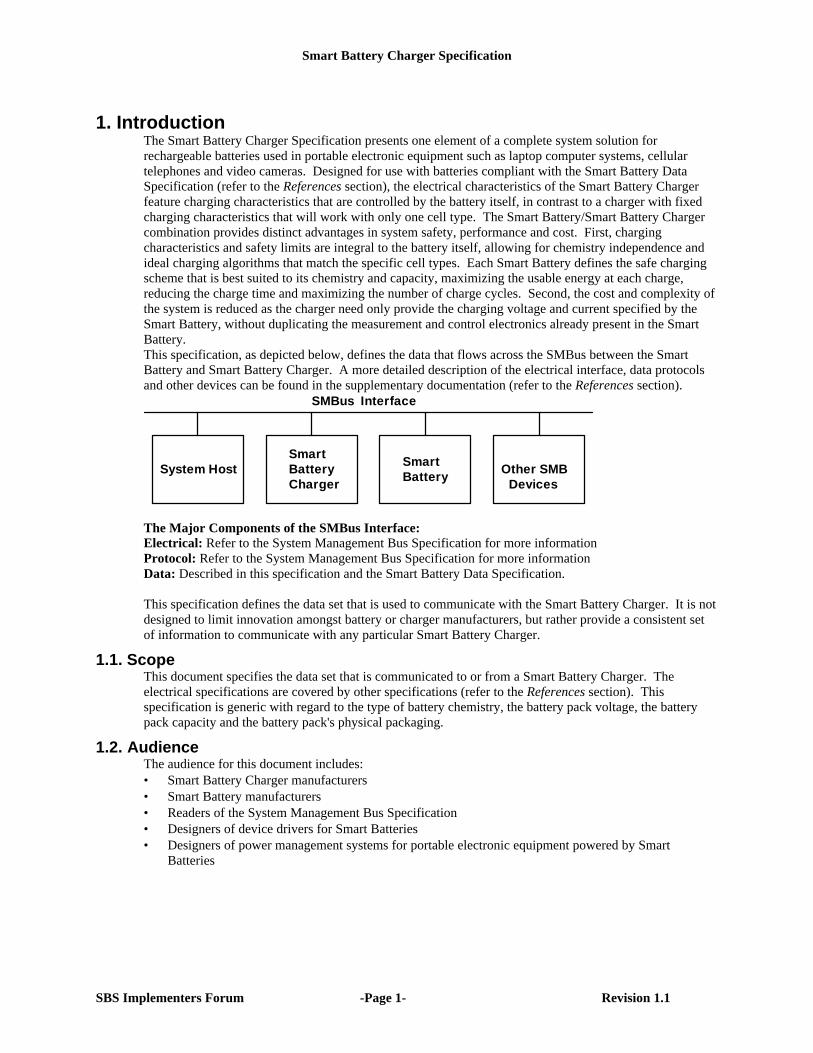
1. IntroductionThe Smart Battery Charger Specification presents one element of a complete system solution forrechargeable batteries used in portable electronic equipment such as laptop computer systems, cellulartelephones and video cameras. Designed for use with batteries compliant with the Smart Battery DataSpecification (refer to the References section), the electrical characteristics of the Smart Battery Chargerfeature charging characteristics that are controlled by the battery itself, in contrast to a charger with fixedcharging characteristics that will work with only one cell type. The Smart Battery/Smart Battery Chargercombination provides distinct advantages in system safety, performance and cost. First, chargingcharacteristics and safety limits are integral to the battery itself, allowing for chemistry independence andideal charging algorithms that match the specific cell types. Each Smart Battery defines the safe chargingscheme that is best suited to its chemistry and capacity, maximizing the usable energy at each charge,reducing the charge time and maximizing the number of charge cycles. Second, the cost and complexity ofthe system is reduced as the charger need only provide the charging voltage and current specified by theSmart Battery, without duplicating the measurement and control electronics already present in the SmartBattery.This specification, as depicted below, defines the data that flows across the SMBus between the SmartBattery and Smart Battery Charger. A more detailed description of the electrical interface, data protocolsand other devices can be found in the supplementary documentation (refer to the References section).
Smart
SMBus Interface
System HostSmart
Other SMBDevices
BatteryChargerBattery
The Major Components of the SMBus Interface:Electrical: Refer to the System Management Bus Specification for more informationProtocol: Refer to the System Management Bus Specification for more informationData: Described in this specification and the Smart Battery Data Specification.
This specification defines the data set that is used to communicate with the Smart Battery Charger. It is notdesigned to limit innovation amongst battery or charger manufacturers, but rather provide a consistent setof information to communicate with any particular Smart Battery Charger.
1.1. ScopeThis document specifies the data set that is communicated to or from a Smart Battery Charger. Theelectrical specifications are covered by other specifications (refer to the References section). Thisspecification is generic with regard to the type of battery chemistry, the battery pack voltage, the batterypack capacity and the battery pack's physical packaging.
1.2. AudienceThe audience for this document includes:• Smart Battery Charger manufacturers• Smart Battery manufacturers• Readers of the System Management Bus Specification• Designers of device drivers for Smart Batteries• Designers of power management systems for portable electronic equipment powered by Smart
Batteries
Smart Battery Charger Specification
SBS Implementers Forum -Page 2- Revision 1.1
2. References• Smart Battery Data Specification, Revision 1.1, SBS-Implementers Forum, December, 1998• Smart Battery Selector Specification, Revision 1.1, SBS-Implementers Forum, December, 1998• Smart Battery System Manager Specification, Revision 1.1, SBS-Implementers Forum, December,
1998• System Management Bus Specification, Revision 1.1, SBS-Implementers Forum, December, 1998• System Management Bus BIOS Interface Specification, Revision 1.0, February 15, 1995• ACPI Specifications, Version 1.0a, Intel Corporation, Microsoft Corporation, Toshiba Corp., July 1998
(http://www.teleport.com/~acpi)• The I²C-bus and how to use it, Philips Semiconductors document #98-8080-575-01.• ACCESS.bus Specifications -- Version 2.2, ACCESS.bus Industry Group, 370 Altair Way Suite 215,
Sunnyvale, CA 94086 Tel (408) 991-3517
3. Definitions• Battery: One or more cells that are designed to provide electrical power.• Cell: The cell is the smallest unit in a battery. Most batteries consist of several cells connected in
series, parallel, or a series-parallel combination.• Host Controller: An intelligent entity that communicates with a Smart Battery and a Smart Battery
Charger, reading the battery’s charge requirements and controlling the battery charger. It can reside inmany places such as: an integrated part of the charger, a stand-alone component or part the SMBushost controller.
• Smart Battery: A battery equipped with specialized hardware that provides present state, calculatedand predicted information to its System Host under software control.
• Smart Battery Charger: A battery charger that periodically communicates over the SMBus with aSmart Battery and can alter its charging characteristics in response to information provided by theSmart Battery. There are two types of Smart Battery Chargers described in this specification: Level 2and Level 3.
• Smart Battery Selector: A Smart Device that controls multiple Smart Batteries in a system. Itestablishes, arbitrates and maintains the power, communication and safety signal paths between theSmart Battery, Smart Battery Charger and the System Host’s power supply.
• Smart Device: An electronic device or module that communicates over the SMBus with the SystemHost and/or other Smart Devices. For example the back-light controller in a Notebook computer canbe implemented as a Smart Device.
• SMBus: The System Management Bus is a specific implementation of an I²C-bus that provides dataprotocols, device addresses and additional electrical requirements that are designed to physicallytransport commands and information between the Smart Battery, System Host, Smart Battery Chargerand other Smart Devices.
• System Host: A piece of portable electronic equipment powered by a Smart Battery which is able tocommunicate with the Smart Battery and use information provided by the battery. The System Host isidentical to the SMBus Host for the purposes of this document.
• Programmatic Maximum: The maximum output level (current or voltage) that the charger is capableof regulating. In calculating output accuracy as a function of full scale output, the programmaticmaximum serves as the full scale output value.
• Packet Error Check (PEC): An additional byte in the SMBus protocols used to check for errors in anSMBus transmission. Refer to the System Management Bus Specification Revision 1.1. A SmartBattery Charger indicates its ability to support PEC with the CHARGER_SPEC value inChargerSpecInfo() function.
Smart Battery Charger Specification
SBS Implementers Forum -Page 3- Revision 1.1
4. Smart Battery Charging SystemA Smart Battery Charging System at a minimum consists of a Smart Battery and Smart Battery Chargercompatible with this specification and those described in the references section.
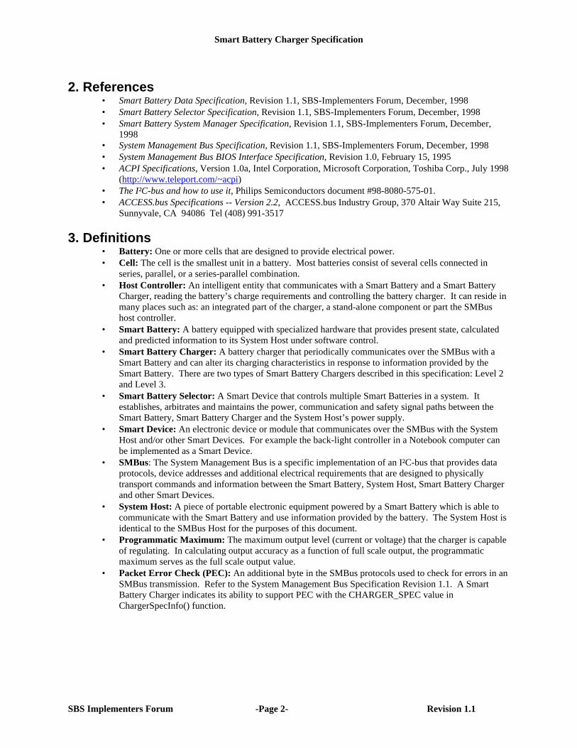
4.1. Smart Battery System Block DiagramsA system may use one or more Smart Batteries. The block diagram of a Smart Battery Charging Systemshown below (notebook computer, video camera, cellular phone, or other portable electronic equipment)depicts a single battery system. For more details about the system components and interactions, see theSmart Battery Data Specification (refer to the References section).
System Host(SMBus Host)
SystemPowerSupply
Smart BatteryCharger
Vcc,+12v,-12v
Critical Events
Battery Data/Status Requests SMBus
AC-DCConverter
DC (Unregulated)/Vbattery
AC
Typical Single Smart Battery System
(Unregulated)
Critical Events
Smart Battery
System PowerControl
DC (Unregulated)Vbattery
SafetySignal
Charging Voltage/CurrentRequests
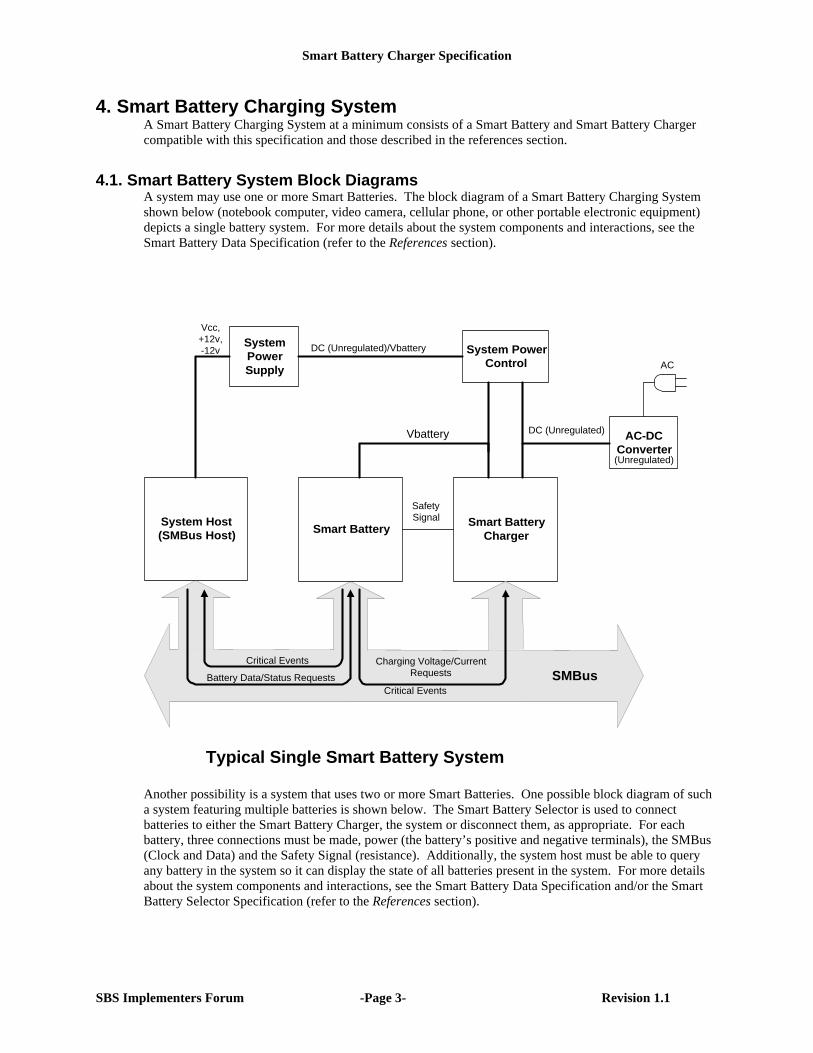
Another possibility is a system that uses two or more Smart Batteries. One possible block diagram of sucha system featuring multiple batteries is shown below. The Smart Battery Selector is used to connectbatteries to either the Smart Battery Charger, the system or disconnect them, as appropriate. For eachbattery, three connections must be made, power (the battery’s positive and negative terminals), the SMBus(Clock and Data) and the Safety Signal (resistance). Additionally, the system host must be able to queryany battery in the system so it can display the state of all batteries present in the system. For more detailsabout the system components and interactions, see the Smart Battery Data Specification and/or the SmartBattery Selector Specification (refer to the References section).
Smart Battery Charger Specification
SBS Implementers Forum -Page 4- Revision 1.1
System Host(SMBus Host)
SystemPowerSupply
Smart BatteryCharger
Smart Battery #1
VCharge
Vcc,+12v,-12v
Critical Events
Battery Data/Status Requests SMBus
AC-DCConverter
DC (Unregulated/battery)AC
Typical Multiple Smart Battery System
(Unregulated)Smart Battery #2
SMBus
SM
Bu
s
SM
Bu
s
Vba
tt
Vba
tt
Saf
ety
Sig
nal
Saf
ety
Sig
nal
SafetySignal
Note: SB #1 powering system SB #2 charging
Smart BatterySelector
The block diagram above shows a two-battery system where Battery 2 is being charged while Battery 1 ispowering the system. This configuration may be used to “condition” Battery 1; allowing it to be fullydischarged prior to recharge.
Smart Battery Charger Specification
SBS Implementers Forum -Page 5- Revision 1.1
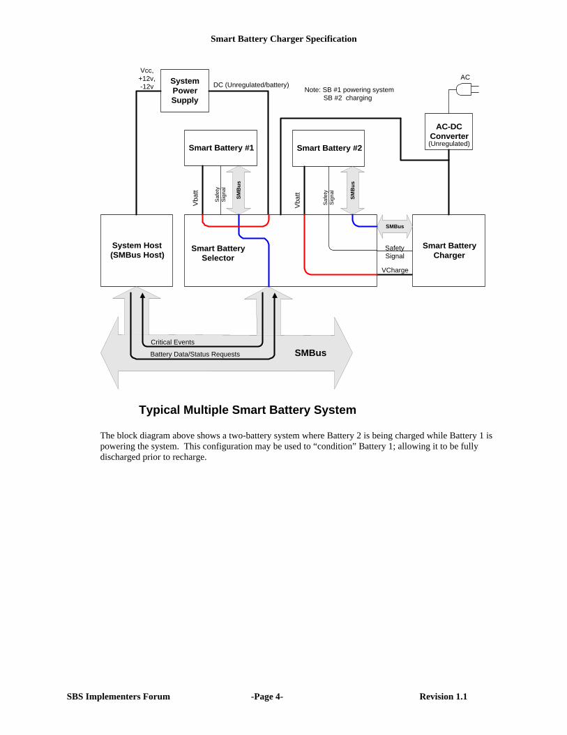
4.2. Smart Battery Charger TypesTwo types of Smart Battery Chargers are defined: Level 2 and Level 3. This document defines a particularset of characteristics and minimum command set for each type of Smart Battery Charger. All SmartBattery Chargers communicate with the Smart Battery using the SMBus; the two types differ in theirSMBus communication mode and whether they modify the charging algorithm of the Smart Battery. Level3 Smart Battery Chargers are supersets of Level 2 chargers and as such support all Level 2 chargercommands. See Section 6 for more detailed characteristics the charger types.
Note: Level 1 Smart Battery Chargers were defined in the version 0.95a specification. While they can
correctly interpret Smart Battery end-of-charge messages minimizing over-charge, they do not providetruly chemistry independent charging. They are no longer defined by the Smart Battery Chargerspecification and are explicitly not compliant with this and subsequent Smart Battery Chargerspecifications.
4.2.1. Level 2 Smart Battery ChargerThe Level 2 or Smart Battery controlled Smart Battery Charger interprets the Smart Battery's criticalwarning messages, and operates as a SMBus slave device that responds to ChargingVoltage() andChargingCurrent() messages sent to it by a Smart Battery. The charger is obliged to adjust its outputcharacteristics in direct response to the ChargingVoltage() and ChargingCurrent() messages it receivesfrom the battery. In Level 2 charging, the Smart Battery is completely responsible for initiating thecommunication and for providing the charging algorithm to the charger. The Smart Battery is in the bestposition to tell the Smart Battery Charger how it needs to be charged. The charging algorithm in thebattery may simply request a static charge condition or may choose to periodically adjust the Smart BatteryCharger's output to meet its present needs. A Level 2 Smart Battery Charger is truly chemistryindependent, and since it is defined as a SMBus slave device only, the Smart Battery Charger is a relativelyinexpensive and easy to implement device.
4.2.2. Level 3 Smart Battery ChargerThe Level 3 Smart Battery Charger not only interprets the Smart Battery's critical warning messages, but isallowed to act as a SMBus master device. In Level 3 charging, the Smart Battery is not necessarilyresponsible for initiating the communication of ChargingCurrent() and ChargingVoltage() values or forproviding the charging algorithm to the charger. The Level 3 Smart Battery Charger may act as a slave orpoll the Smart Battery to determine the charging voltage and current the battery desires, and thendynamically adjust its output to meet the battery's charging requirements. This method of Level 3 chargingmaintains the chemistry independence property of the charger since Smart Battery is in the best position totell the Smart Battery Charger how it wants to be charged.
A Level 3 Smart Battery Charger is free to implement an alternative specialized charging algorithm. It mayalso interrogate the Smart Battery for any other relevant data, such as time remaining to full charge, batterytemperature or other data used to control proper charging or discharge conditioning. For example, amedical device with stricter temperature limits than the Smart Battery's self-contained charging algorithm,may use a Level 3 Smart Battery Charger that factors in the battery's reported temperature into its chargingalgorithm.
The Level 3 Smart Battery Charger may be chemistry independent like the Level 2 charger. Because itsupports SMBus Master Mode, the Level 3 Smart Battery Charger is more complex, thus more expensive
Charger Type by SMBus mode and charge algorithm source.
Charge AlgorithmSMBus mode
Battery Modified from Battery
Slave only Level 2 Level 3
Slave/Master Level 3 Level 3
Smart Battery Charger Specification
SBS Implementers Forum -Page 6- Revision 1.1
than a Level 2 charger. In some cases, a system designer may choose to use the system host tocommunicate with both the Smart Battery and a Level 2 Smart Battery Charger to provide a hybrid Level 3functionality.
4.3. Interface DefinitionThe interface is separated into two types: normal communications that are either Smart Battery-to-SmartBattery Charger or Smart Battery Charger-to-Smart Battery, and critical communications that areexclusively Smart Battery-to-Smart Battery Charger. None of the communications require the system’sHost take any action to control charging.
4.3.1. Typical Communications between a Smart Battery-and-Smart Battery ChargerCommunication between the Smart Battery and the Smart Battery Charger may be initiated by either thebattery or the charger depending upon the specific implementation, but the same minimum set ofinformation is exchanged between the battery and the charger, regardless of which device initiated thetransaction. For example, a Level 3 Smart Battery Charger may poll the battery periodically to determinethe appropriate charge voltage and current, while a Level 2 charger must wait for the battery to initiate thedata transmission. In both cases, data (charging voltage and current) is supplied by the battery to thecharger.
Smart Battery to Smart Battery Charger communications are performed:• To allow the Smart Battery to instruct the Smart Battery Charger to set the appropriate charge current
and charge voltage.• To allow access to the "correct" charge algorithm for the battery.• To allow Smart Batteries to be charged as rapidly and as safely as possible.• To allow new and different battery technologies to be used in existing equipment.
4.3.2. Critical Communications from a Smart Battery to the Smart Battery ChargerA Smart Battery must have the ability to inform the Smart Battery Charger of potentially dangerousconditions. These notifications represent a critical effort on the part of the battery to inform the SmartBattery Charger and System Host that the battery is being overcharged. The Smart Battery expects theSmart Battery Charger and/or the System Host to take the appropriate corrective action.
Smart Battery-to-Smart Battery Charger or System Host communications are performed:• To allow the Smart Battery to instruct the Smart Battery Charger to discontinue charging due to:
♦ over charge♦ end of normal charge♦ over temperature.
• To allow the Smart Battery to instruct the Smart Battery Charger to restart charging when:♦ the battery alarm conditions have returned to normal♦ an end of discharge cycle has occurred during battery conditioning.
Smart Battery Charger Specification
SBS Implementers Forum -Page 7- Revision 1.1
4.4. Error Detection and SignalingThe Smart Battery Charger supports the SMBus method for error signaling. This error system is designedto minimize the amount of traffic on the SMBus and the amount of code required to communicate with thecharger.
4.4.1. Error DetectionWhen a Smart Battery Charger detects an error condition (such as an unsupported command, dataunavailable, busy or bad data) it signals the master (Smart Battery or System Host) that an error has beendetected. All functions processed by the Smart Battery Charger are assumed to be error-free unless theSmart Battery Charger signals the master device that an error has occurred.
4.4.2. Error SignalingA Smart Battery Charger signals the SMBus master device that it has detected an unrecoverable error bytaking advantage of the SMBus requirement that an acknowledge bit must be sent by the slave after everybyte is transferred. When the Smart Battery Charger fails to provide the acknowledge bit, the SMBusmaster device is obliged to generate a STOP condition, thus causing a premature termination of thetransfer. This signals the SMBus master device that an error has occurred.
The Smart Battery Charger must ALWAYS acknowledge its own address. Failure to do so may cause theSystem Host or Smart Battery to incorrectly assume the Smart Battery Charger is NOT present in thesystem. The Smart Battery Charger may choose not to acknowledge any byte following its address if it isbusy or otherwise unable to respond.
Smart Battery Charger Specification
SBS Implementers Forum -Page 8- Revision 1.1
5. Smart Battery Charger CommandsThe battery or the charger, depending upon the specific implementation may initiate communicationbetween the Smart Battery and Smart Battery Charger. In either case, the same minimum set ofinformation is transmitted between the battery and the charger. It is important to note that thiscommunication does not require host intervention and depending upon implementation, allows forsuccessful charging even when the system host is not powered or is absent.
Level 2 chargers are always slave devices and therefore all communication with these chargers is initiatedby the Smart Battery or other master device, typically the System Host. Whenever the Smart Battery'sBatteryMode() CHARGER_MODE bit is cleared (default) and the Smart Battery desires to be charged anddetects the presence of a Smart Battery Charger (optional), it will send the ChargingCurrent() andChargingVoltage() values to the Smart Battery Charger. The Smart Battery will continue broadcastingBOTH of these values an interval of not less than 5 seconds nor greater than 1 minute in order to maintaincorrect charging. For example, the Smart Battery may detect the presence of a Smart Battery Charger byrecognizing a charge current or voltage at the battery terminals and begin regular broadcasts to the charger.Even if no Smart Battery Charger is present, the Smart Battery may choose to broadcast to the chargeraddress. See Smart Battery Data Specification for details (refer to the References section).
Level 3 Smart Battery Chargers may initiate charging by interrogating the Smart Battery forChargingCurrent() and/or ChargingVoltage(). For example, this may be initiated by the presence of acharge source, such as an A-C wall adapter, or by direct command of the system host. Further, Level 3Smart Battery Chargers must also operate as slave devices in the same manner as Level 2 chargers.
Whenever the Smart Battery detects a critical condition, it will become a bus master and send anAlarmWarning() message to both the Smart Battery Charger and the System Host, as appropriate, to notifythem of the critical condition. The message sent by the AlarmWarning() function is similar to the messagereturned by the BatteryStatus() function. All Smart Battery Chargers must discontinue charging uponreceipt of an AlarmWarning() message if the error indicates that charging should be terminated. See thedescription of the AlarmWarning() function for a list of the alarms that should terminate charging.
The following functions are used by the Smart Battery Charger system to communicate with a SystemHost, Smart Battery and other devices connected via the SMBus. All functions include a command andthen either read or write a 2-byte word. For more details about the data structure and communicationprotocol, see the System Management Bus Specification (refer to the References section).
The default mode of the Smart Battery Charger described by this specification does not use thevoltage and current scaling information contained in the Smart Battery’s SpecificationInfo(). Thecharger interprets all voltage and current commands using one as the scaling factor. A Level 3charger is allowed to use the battery’s scaling information in a non-default mode.
Smart Battery Charger Specification
SBS Implementers Forum -Page 9- Revision 1.1
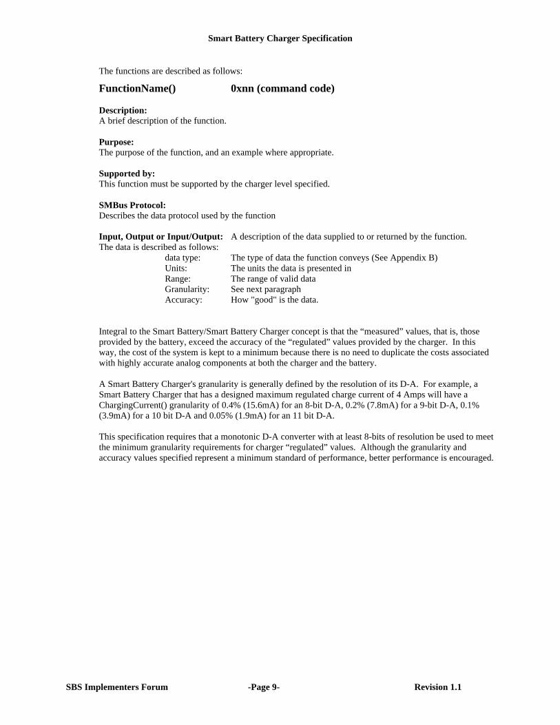
The functions are described as follows:
FunctionName() 0xnn (command code)
Description:A brief description of the function.
Purpose:The purpose of the function, and an example where appropriate.
Supported by:This function must be supported by the charger level specified.
SMBus Protocol:Describes the data protocol used by the function
Input, Output or Input/Output: A description of the data supplied to or returned by the function.The data is described as follows:
data type: The type of data the function conveys (See Appendix B)Units: The units the data is presented inRange: The range of valid dataGranularity: See next paragraphAccuracy: How "good" is the data.
Integral to the Smart Battery/Smart Battery Charger concept is that the “measured” values, that is, thoseprovided by the battery, exceed the accuracy of the “regulated” values provided by the charger. In thisway, the cost of the system is kept to a minimum because there is no need to duplicate the costs associatedwith highly accurate analog components at both the charger and the battery.
A Smart Battery Charger's granularity is generally defined by the resolution of its D-A. For example, aSmart Battery Charger that has a designed maximum regulated charge current of 4 Amps will have aChargingCurrent() granularity of 0.4% (15.6mA) for an 8-bit D-A, 0.2% (7.8mA) for a 9-bit D-A, 0.1%(3.9mA) for a 10 bit D-A and 0.05% (1.9mA) for an 11 bit D-A.
This specification requires that a monotonic D-A converter with at least 8-bits of resolution be used to meetthe minimum granularity requirements for charger “regulated” values. Although the granularity andaccuracy values specified represent a minimum standard of performance, better performance is encouraged.
Smart Battery Charger Specification
SBS Implementers Forum -Page 10- Revision 1.1
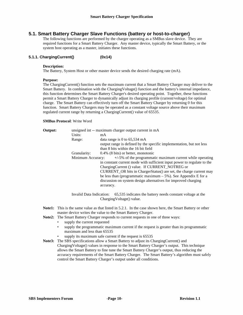
5.1. Smart Battery Charger Slave Functions (battery or host-to-charger)The following functions are performed by the charger operating as a SMBus slave device. They arerequired functions for a Smart Battery Charger. Any master device, typically the Smart Battery, or thesystem host operating as a master, initiates these functions.
5.1.1. ChargingCurrent() (0x14)
Description:The Battery, System Host or other master device sends the desired charging rate (mA).
Purpose:The ChargingCurrent() function sets the maximum current that a Smart Battery Charger may deliver to theSmart Battery. In combination with the ChargingVoltage() function and the battery's internal impedance,this function determines the Smart Battery Charger's desired operating point. Together, these functionspermit a Smart Battery Charger to dynamically adjust its charging profile (current/voltage) for optimalcharge. The Smart Battery can effectively turn off the Smart Battery Charger by returning 0 for thisfunction. Smart Battery Chargers may be operated as a constant voltage source above their maximumregulated current range by returning a ChargingCurrent() value of 65535.
SMBus Protocol: Write Word
Output: unsigned int -- maximum charger output current in mAUnits: mARange: data range is 0 to 65,534 mA
output range is defined by the specific implementation, but not lessthan 8 bits within the 16 bit field
Granularity: 0.4% (8 bits) or better, monotonicMinimum Accuracy: +/-5% of the programmatic maximum current while operating
in constant current mode with sufficient input power to regulate to theChargingCurrent () value. If CURRENT_NOTREG orCURRENT_OR bits in ChargerStatus() are set, the charge current maybe less than (programmatic maximum – 5%). See Appendix E for adiscussion on system design alternatives for improved chargingaccuracy.
Invalid Data Indication: 65,535 indicates the battery needs constant voltage at theChargingVoltage() value.
Note1: This is the same value as that listed in 5.2.1. In the case shown here, the Smart Battery or othermaster device writes the value to the Smart Battery Charger.
Note2: The Smart Battery Charger responds to current requests in one of three ways:• supply the current requested• supply the programmatic maximum current if the request is greater than its programmatic
maximum and less than 65535• supply its maximum safe current if the request is 65535
Note3: The SBS specifications allow a Smart Battery to adjust its ChargingCurrent() andChargingVoltage() values in response to the Smart Battery Charger’s output. This techniqueallows the Smart Battery to fine tune the Smart Battery Charger’s output, thus reducing theaccuracy requirements of the Smart Battery Charger. The Smart Battery’s algorithm must safelycontrol the Smart Battery Charger’s output under all conditions.
Smart Battery Charger Specification
SBS Implementers Forum -Page 11- Revision 1.1
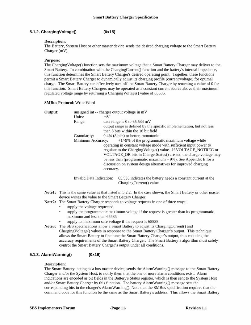
5.1.2. ChargingVoltage() (0x15) Description: The Battery, System Host or other master device sends the desired charging voltage to the Smart BatteryCharger (mV). Purpose: The ChargingVoltage() function sets the maximum voltage that a Smart Battery Charger may deliver to theSmart Battery. In combination with the ChargingCurrent() function and the battery's internal impedance,this function determines the Smart Battery Charger's desired operating point. Together, these functionspermit a Smart Battery Charger to dynamically adjust its charging profile (current/voltage) for optimalcharge. The Smart Battery can effectively turn off the Smart Battery Charger by returning a value of 0 forthis function. Smart Battery Chargers may be operated as a constant current source above their maximumregulated voltage range by returning a ChargingVoltage() value of 65535. SMBus Protocol: Write Word Output: unsigned int -- charger output voltage in mV
Units: mV Range: data range is 0 to 65,534 mV
output range is defined by the specific implementation, but not lessthan 8 bits within the 16 bit field
Granularity: 0.4% (8 bits) or better, monotonicMinimum Accuracy: +1/-9% of the programmatic maximum voltage while
operating in constant voltage mode with sufficient input power toregulate to the ChargingVoltage() value. If VOLTAGE_NOTREG orVOLTAGE_OR bits in ChargerStatus() are set, the charge voltage maybe less than (programmatic maximum – 9%). See Appendix E for adiscussion on system design alternatives for improved chargingaccuracy.
Invalid Data Indication: 65,535 indicates the battery needs a constant current at the
ChargingCurrent() value. Note1: This is the same value as that listed in 5.2.2. In the case shown, the Smart Battery or other master
device writes the value to the Smart Battery Charger. Note2: The Smart Battery Charger responds to voltage requests in one of three ways:
• supply the voltage requested• supply the programmatic maximum voltage if the request is greater than its programmatic
maximum and less than 65535• supply its maximum safe voltage if the request is 65535
Note3: The SBS specifications allow a Smart Battery to adjust its ChargingCurrent() andChargingVoltage() values in response to the Smart Battery Charger’s output. This techniqueallows the Smart Battery to fine tune the Smart Battery Charger’s output, thus reducing theaccuracy requirements of the Smart Battery Charger. The Smart Battery’s algorithm must safelycontrol the Smart Battery Charger’s output under all conditions.
5.1.3. AlarmWarning() (0x16)
Description:The Smart Battery, acting as a bus master device, sends the AlarmWarning() message to the Smart BatteryCharger and/or the System Host, to notify them that the one or more alarm conditions exist. Alarmindications are encoded as bit fields in the Battery's Status register, which is then sent to the System Hostand/or Smart Battery Charger by this function. The battery AlarmWarning() message sets thecorresponding bits in the charger's AlarmWarning(). Note that the SMBus specification requires that thecommand code for this function be the same as the Smart Battery's address. This allows the Smart Battery
Smart Battery Charger Specification
SBS Implementers Forum -Page 12- Revision 1.1
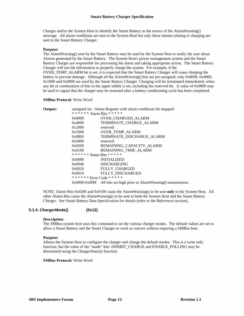
Charger and/or the System Host to identify the Smart Battery as the source of the AlarmWarning()message. All alarm conditions are sent to the System Host but only those alarms relating to charging aresent to the Smart Battery Charger.
Purpose:The AlarmWarning() sent by the Smart Battery may be used by the System Host to notify the user aboutAlarms generated by the Smart Battery. The System Host's power management system and the SmartBattery Charger are responsible for processing the alarm and taking appropriate action. The Smart BatteryCharger will use the information to properly charge the system. For example, if theOVER_TEMP_ALARM bit is set, it is expected that the Smart Battery Charger will cease charging thebattery to prevent damage. Although all the AlarmWarning() bits are pre-assigned, only 0x8000, 0x4000,0x1000 and 0x0800 are used by the Smart Battery Charger. Charging will be terminated immediately whenany bit or combination of bits in the upper nibble is set, including the reserved bit. A value of 0x0800 maybe used to signal that the charger may be restarted after a battery conditioning cycle has been completed.
SMBus Protocol: Write Word
Output: unsigned int - Status Register with alarm conditions bit mapped:* * * * * * Alarm Bits * * * * *0x8000 OVER_CHARGED_ALARM0x4000 TERMINATE_CHARGE_ALARM0x2000 reserved0x1000 OVER_TEMP_ALARM0x0800 TERMINATE_DISCHARGE_ALARM0x0400 reserved0x0200 REMAINING_CAPACITY_ALARM0x0100 REMAINING_TIME_ALARM* * * * * * Status Bits * * * * *0x0080 INITIALIZED0x0040 DISCHARGING0x0020 FULLY_CHARGED0x0010 FULLY_DISCHARGED* * * * * * Error Code * * * * *0x0000-0x000f All bits set high prior to AlarmWarning() transmission.
NOTE: Alarm Bits 0x0200 and 0x0100 cause the AlarmWarning() to be sent only to the System Host. Allother Alarm Bits cause the AlarmWarning() to be sent to both the System Host and the Smart BatteryCharger. See Smart Battery Data Specification for details (refer to the References section).
5.1.4. ChargerMode() (0x12)
Description:The SMBus system host uses this command to set the various charger modes. The default values are set toallow a Smart Battery and the Smart Charger to work in concert without requiring a SMBus host.
Purpose:Allows the System Host to configure the charger and change the default modes. This is a write onlyfunction, but the value of the "mode" bits: INHIBIT_CHARGE and ENABLE_POLLING may bedetermined using the ChargerStatus() function.
SMBus Protocol: Write Word
Smart Battery Charger Specification
SBS Implementers Forum -Page 13- Revision 1.1
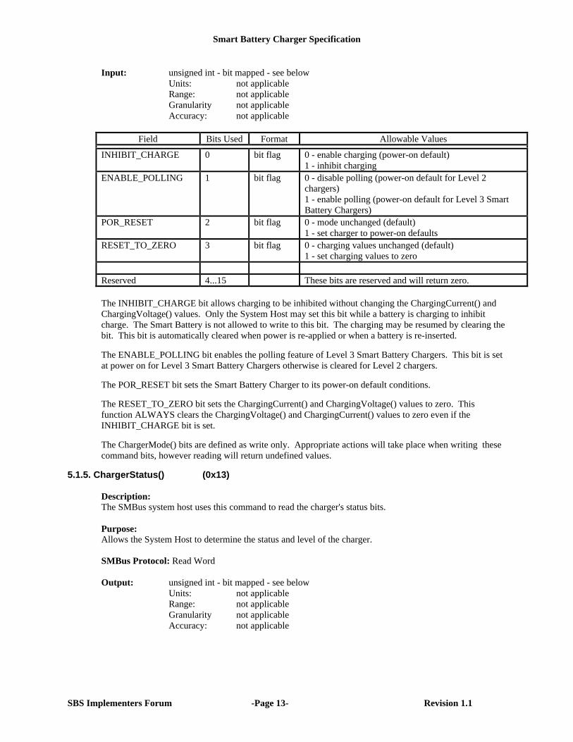
Input: unsigned int - bit mapped - see belowUnits: not applicableRange: not applicableGranularity not applicableAccuracy: not applicable
Field Bits Used Format Allowable Values
INHIBIT_CHARGE 0 bit flag 0 - enable charging (power-on default)1 - inhibit charging
ENABLE_POLLING 1 bit flag 0 - disable polling (power-on default for Level 2chargers)1 - enable polling (power-on default for Level 3 SmartBattery Chargers)
POR_RESET 2 bit flag 0 - mode unchanged (default)1 - set charger to power-on defaults
RESET_TO_ZERO 3 bit flag 0 - charging values unchanged (default)1 - set charging values to zero
Reserved 4...15 These bits are reserved and will return zero.
The INHIBIT_CHARGE bit allows charging to be inhibited without changing the ChargingCurrent() andChargingVoltage() values. Only the System Host may set this bit while a battery is charging to inhibitcharge. The Smart Battery is not allowed to write to this bit. The charging may be resumed by clearing thebit. This bit is automatically cleared when power is re-applied or when a battery is re-inserted.
The ENABLE_POLLING bit enables the polling feature of Level 3 Smart Battery Chargers. This bit is setat power on for Level 3 Smart Battery Chargers otherwise is cleared for Level 2 chargers.
The POR_RESET bit sets the Smart Battery Charger to its power-on default conditions.
The RESET_TO_ZERO bit sets the ChargingCurrent() and ChargingVoltage() values to zero. Thisfunction ALWAYS clears the ChargingVoltage() and ChargingCurrent() values to zero even if theINHIBIT_CHARGE bit is set.
The ChargerMode() bits are defined as write only. Appropriate actions will take place when writing thesecommand bits, however reading will return undefined values.
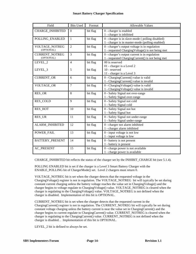
5.1.5. ChargerStatus() (0x13)
Description:The SMBus system host uses this command to read the charger's status bits.
Purpose:Allows the System Host to determine the status and level of the charger.
SMBus Protocol: Read Word
Output: unsigned int - bit mapped - see belowUnits: not applicableRange: not applicableGranularity not applicableAccuracy: not applicable
Smart Battery Charger Specification
SBS Implementers Forum -Page 14- Revision 1.1
Field Bits Used Format Allowable Values
CHARGE_INHIBITED 0 bit flag 0 - charger is enabled1 - charger is inhibited
POLLING_ENABLED 1 bit flag 0 - charger is in slave-mode ( polling disabled)1 - charger is in master-mode (polling enabled)
VOLTAGE_NOTREG (OPTIONAL)
2 bit flag 0 - charger’s output voltage is in regulation1 - requested ChargingVoltage() is not being met
CURRENT_NOTREG (OPTIONAL)
3 bit flag 0 - charger’s output current is in regulation1 - requested ChargingCurrent() is not being met
LEVEL_2 4 bit flag 00 is reserved01 - charger is a Level 2
LEVEL_3 5 bit flag 10 - reserved11 - charger is a Level 3
CURRENT_OR 6 bit flag 0 - ChargingCurrent() value is valid1 - ChargingCurrent() value is invalid
VOLTAGE_OR 7 bit flag 0 - ChargingVoltage() value is valid1 - ChargingVoltage() value is invalid
RES_OR 8 bit flag 0 - Safety Signal not over-range1 - Safety Signal over-range
RES_COLD 9 bit flag 0 - Safety Signal not cold1 - Safety Signal cold
RES_HOT 10 bit flag 0 - Safety Signal not hot1 - Safety Signal hot
RES_UR 11 bit flag 0 - Safety Signal not under-range1 - Safety Signal under-range
ALARM_INHIBITED 12 bit flag 0 - charger not alarm inhibited1 - charger alarm inhibited
POWER_FAIL 13 bit flag 0 - input voltage is not low1 - input voltage is low
BATTERY_PRESENT 14 bit flag 0 - battery is not present1 - battery is present
AC_PRESENT 15 bit flag 0 - charge power is not available1 - charge power is available
CHARGE_INHIBITED bit reflects the status of the charger set by the INHIBIT_CHARGE bit (see 5.1.4).
POLLING ENABLED bit is set if the charger is a Level 3 Smart Battery Charger with theENABLE_POLLING bit of ChargerMode() set. Level 2 chargers must return 0.
VOLTAGE_NOTREG bit is set when the charger detects that the requested voltage in theChargingVoltage() register is not in regulation. The VOLTAGE_NOTREG bit will typically be set duringconstant current charging unless the battery voltage reaches the value set in ChargingVoltage() and thecharger begins to voltage regulate to ChargingVoltage() value. VOLTAGE_NOTREG is cleared when thecharger is regulating to the ChargingVoltage() value. VOLTAGE_NOTREG is not defined when thecharger is disabled. Implementation of this bit is OPTIONAL.
CURRENT_NOTREG bit is set when the charger detects that the requested current in theChargingCurrent() register is not in regulation. The CURRENT_NOTREG bit will typically be set duringconstant voltage charging unless the battery current is near the value set in ChargingCurrent() and thecharger begins to current regulate to ChargingCurrent() value. CURRENT_NOTREG is cleared when thecharger is regulating to the ChargingCurrent() value. CURRENT_NOTREG is not defined when thecharger is disabled. . Implementation of this bit is OPTIONAL.
LEVEL_2 bit is defined to always be set.
Smart Battery Charger Specification
SBS Implementers Forum -Page 15- Revision 1.1
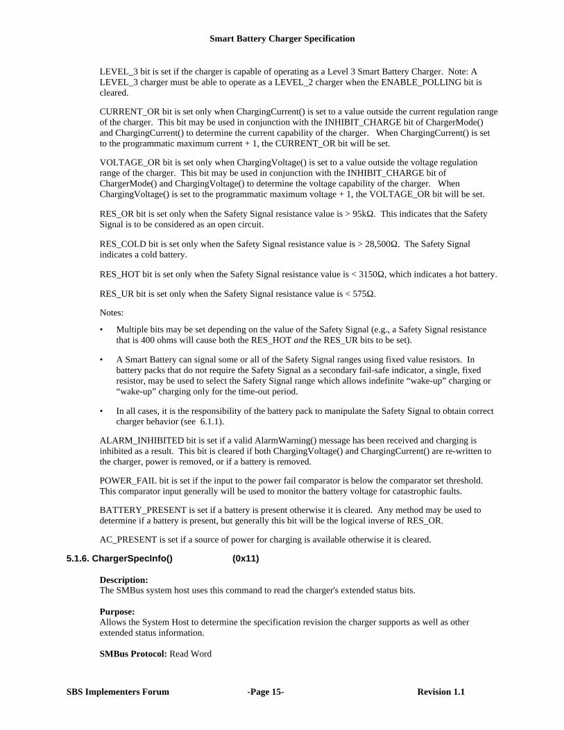
LEVEL_3 bit is set if the charger is capable of operating as a Level 3 Smart Battery Charger. Note: ALEVEL_3 charger must be able to operate as a LEVEL_2 charger when the ENABLE_POLLING bit iscleared.
CURRENT_OR bit is set only when ChargingCurrent() is set to a value outside the current regulation rangeof the charger. This bit may be used in conjunction with the INHIBIT_CHARGE bit of ChargerMode()and ChargingCurrent() to determine the current capability of the charger. When ChargingCurrent() is setto the programmatic maximum current + 1, the CURRENT_OR bit will be set.
VOLTAGE_OR bit is set only when ChargingVoltage() is set to a value outside the voltage regulationrange of the charger. This bit may be used in conjunction with the INHIBIT_CHARGE bit ofChargerMode() and ChargingVoltage() to determine the voltage capability of the charger. WhenChargingVoltage() is set to the programmatic maximum voltage + 1, the VOLTAGE_OR bit will be set.
RES_OR bit is set only when the Safety Signal resistance value is > 95kΩ. This indicates that the SafetySignal is to be considered as an open circuit.
RES_COLD bit is set only when the Safety Signal resistance value is > 28,500Ω. The Safety Signalindicates a cold battery.
RES_HOT bit is set only when the Safety Signal resistance value is < 3150Ω, which indicates a hot battery.
RES_UR bit is set only when the Safety Signal resistance value is < 575Ω.
Notes:
• Multiple bits may be set depending on the value of the Safety Signal (e.g., a Safety Signal resistancethat is 400 ohms will cause both the RES_HOT and the RES_UR bits to be set).
• A Smart Battery can signal some or all of the Safety Signal ranges using fixed value resistors. Inbattery packs that do not require the Safety Signal as a secondary fail-safe indicator, a single, fixedresistor, may be used to select the Safety Signal range which allows indefinite “wake-up” charging or“wake-up” charging only for the time-out period.
• In all cases, it is the responsibility of the battery pack to manipulate the Safety Signal to obtain correctcharger behavior (see 6.1.1).
ALARM_INHIBITED bit is set if a valid AlarmWarning() message has been received and charging isinhibited as a result. This bit is cleared if both ChargingVoltage() and ChargingCurrent() are re-written tothe charger, power is removed, or if a battery is removed.
POWER_FAIL bit is set if the input to the power fail comparator is below the comparator set threshold.This comparator input generally will be used to monitor the battery voltage for catastrophic faults.
BATTERY_PRESENT is set if a battery is present otherwise it is cleared. Any method may be used todetermine if a battery is present, but generally this bit will be the logical inverse of RES_OR.
AC_PRESENT is set if a source of power for charging is available otherwise it is cleared.
5.1.6. ChargerSpecInfo() (0x11)
Description:The SMBus system host uses this command to read the charger's extended status bits.
Purpose:Allows the System Host to determine the specification revision the charger supports as well as otherextended status information.
SMBus Protocol: Read Word
Smart Battery Charger Specification
SBS Implementers Forum -Page 16- Revision 1.1
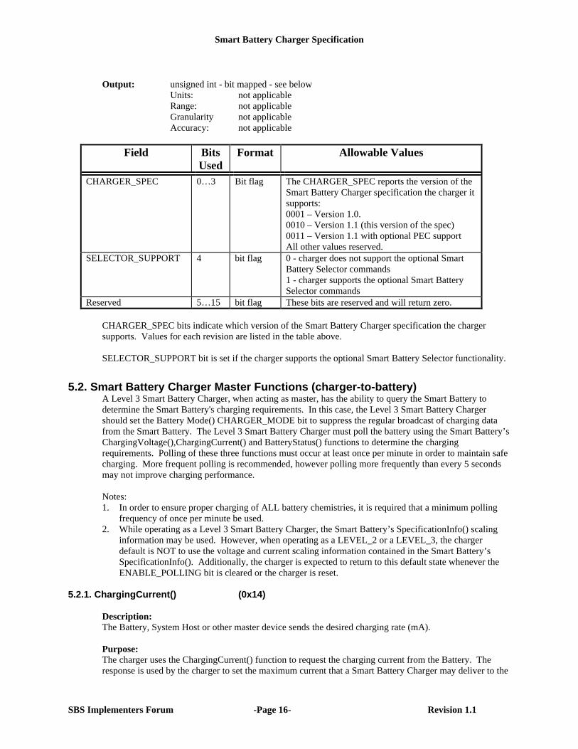
Output: unsigned int - bit mapped - see belowUnits: not applicableRange: not applicableGranularity not applicableAccuracy: not applicable
Field BitsUsed
Format Allowable Values
CHARGER_SPEC 0…3 Bit flag The CHARGER_SPEC reports the version of theSmart Battery Charger specification the charger itsupports:0001 – Version 1.0.0010 – Version 1.1 (this version of the spec)0011 – Version 1.1 with optional PEC supportAll other values reserved.
SELECTOR_SUPPORT 4 bit flag 0 - charger does not support the optional SmartBattery Selector commands1 - charger supports the optional Smart BatterySelector commands
Reserved 5…15 bit flag These bits are reserved and will return zero.
CHARGER_SPEC bits indicate which version of the Smart Battery Charger specification the chargersupports. Values for each revision are listed in the table above.
SELECTOR_SUPPORT bit is set if the charger supports the optional Smart Battery Selector functionality.
5.2. Smart Battery Charger Master Functions (charger-to-battery)A Level 3 Smart Battery Charger, when acting as master, has the ability to query the Smart Battery todetermine the Smart Battery's charging requirements. In this case, the Level 3 Smart Battery Chargershould set the Battery Mode() CHARGER_MODE bit to suppress the regular broadcast of charging datafrom the Smart Battery. The Level 3 Smart Battery Charger must poll the battery using the Smart Battery’sChargingVoltage(),ChargingCurrent() and BatteryStatus() functions to determine the chargingrequirements. Polling of these three functions must occur at least once per minute in order to maintain safecharging. More frequent polling is recommended, however polling more frequently than every 5 secondsmay not improve charging performance.
Notes:1. In order to ensure proper charging of ALL battery chemistries, it is required that a minimum polling
frequency of once per minute be used.2. While operating as a Level 3 Smart Battery Charger, the Smart Battery’s SpecificationInfo() scaling
information may be used. However, when operating as a LEVEL_2 or a LEVEL_3, the chargerdefault is NOT to use the voltage and current scaling information contained in the Smart Battery’sSpecificationInfo(). Additionally, the charger is expected to return to this default state whenever theENABLE_POLLING bit is cleared or the charger is reset.
5.2.1. ChargingCurrent() (0x14)
Description:The Battery, System Host or other master device sends the desired charging rate (mA).
Purpose:The charger uses the ChargingCurrent() function to request the charging current from the Battery. Theresponse is used by the charger to set the maximum current that a Smart Battery Charger may deliver to the
Smart Battery Charger Specification
SBS Implementers Forum -Page 17- Revision 1.1
Smart Battery. In combination with the ChargingVoltage() function and the battery's internal impedance,this function determines the Smart Battery Charger's desired operating point. Together, these functionspermit a Smart Battery Charger to dynamically adjust its charging profile (current/voltage) for optimalcharge. The Smart Battery can effectively turn off the Smart Battery Charger by returning 0 for thisfunction. Smart Battery Chargers may be operated as a constant voltage source above their maximumregulated current range by returning a ChargingCurrent() value of 65535.
Supported by: Level 3 Smart Battery Charger
SMBus Protocol: Write Word
Output: unsigned int -- maximum charger output current in mAUnits: mARange: data range is 0 to 65,534 mA
output range is defined by the specific implementation, but not lessthan 8 bits within the 16 bit field
Granularity: 0.4% (8 bits) or better, monotonicMinimum Accuracy: +/-5% of the programmatic maximum current while operating
in constant current mode with sufficient input power to regulate to theChargingCurrent () value. If CURRENT_NOTREG orCURRENT_OR bits in ChargerStatus() are set, the charge current maybe less than (programmatic maximum – 5%). See Appendix E for adiscussion on system design alternatives for improved chargingaccuracy.
Invalid Data Indication: 65,535 indicates the battery needs constant voltage at theChargingVoltage() value.
Note1: This is the same value as that listed in 5.1.1. In the case shown here, the value is read by theSmart Battery Charger from the Smart Battery.
Note2: The Smart Battery Charger responds to current requests in one of three ways:• supply the current requested• supply the programmatic maximum current if the request is greater than its programmatic
maximum and less than 65535• supply its maximum safe current if the request is 65535
Note3: The SBS specifications allow a Smart Battery to adjust its ChargingCurrent() andChargingVoltage() values in response to the Smart Battery Charger’s output. This techniqueallows the Smart Battery to fine tune the Smart Battery Charger’s output, thus reducing theaccuracy requirements of the Smart Battery Charger. The Smart Battery’s algorithm must safelycontrol the Smart Battery Charger’s output under all conditions.
5.2.2. ChargingVoltage() (0x15)
Description: The Battery, System Host or other master device sends the desired charging voltage to the Smart BatteryCharger (mV). Purpose: The ChargingVoltage() function sets the maximum voltage that a Smart Battery Charger may deliver to theSmart Battery. In combination with the ChargingCurrent() function and the battery's internal impedance,this function determines the Smart Battery Charger's desired operating point. Together, these functionspermit a Smart Battery Charger to dynamically adjust its charging profile (current/voltage) for optimalcharge. The Smart Battery can effectively turn off the Smart Battery Charger by returning a value of 0 forthis function. Smart Battery Chargers may be operated as a constant current source above their maximumregulated voltage range by returning a ChargingVoltage() value of 65535.
Smart Battery Charger Specification
SBS Implementers Forum -Page 18- Revision 1.1
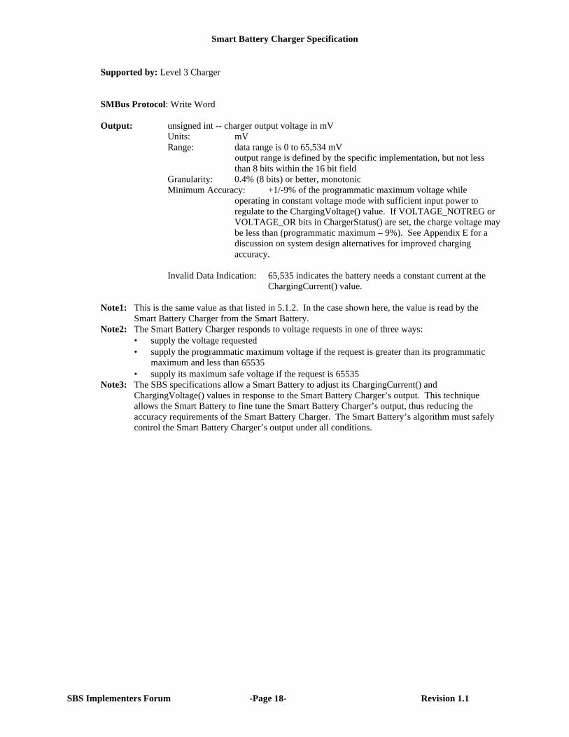
Supported by: Level 3 Charger
SMBus Protocol: Write Word Output: unsigned int -- charger output voltage in mV
Units: mV Range: data range is 0 to 65,534 mV
output range is defined by the specific implementation, but not lessthan 8 bits within the 16 bit field
Granularity: 0.4% (8 bits) or better, monotonicMinimum Accuracy: +1/-9% of the programmatic maximum voltage while
operating in constant voltage mode with sufficient input power toregulate to the ChargingVoltage() value. If VOLTAGE_NOTREG orVOLTAGE_OR bits in ChargerStatus() are set, the charge voltage maybe less than (programmatic maximum – 9%). See Appendix E for adiscussion on system design alternatives for improved chargingaccuracy.
Invalid Data Indication: 65,535 indicates the battery needs a constant current at the
ChargingCurrent() value. Note1: This is the same value as that listed in 5.1.2. In the case shown here, the value is read by the
Smart Battery Charger from the Smart Battery. Note2: The Smart Battery Charger responds to voltage requests in one of three ways:
• supply the voltage requested• supply the programmatic maximum voltage if the request is greater than its programmatic
maximum and less than 65535• supply its maximum safe voltage if the request is 65535
Note3: The SBS specifications allow a Smart Battery to adjust its ChargingCurrent() andChargingVoltage() values in response to the Smart Battery Charger’s output. This techniqueallows the Smart Battery to fine tune the Smart Battery Charger’s output, thus reducing theaccuracy requirements of the Smart Battery Charger. The Smart Battery’s algorithm must safelycontrol the Smart Battery Charger’s output under all conditions.
Smart Battery Charger Specification
SBS Implementers Forum -Page 19- Revision 1.1
6. Smart Battery Charger CharacteristicsSmart Battery Chargers are differentiated by their type (see Smart Battery Charger types in this document).Each type has certain characteristics and supports certain functions. This section describes thecharacteristics and functions all chargers have in common as well as those that are type specific.
6.1. Common Smart Battery Charger CharacteristicsAll Smart Battery Chargers have the following capabilities, characteristics and options in common.
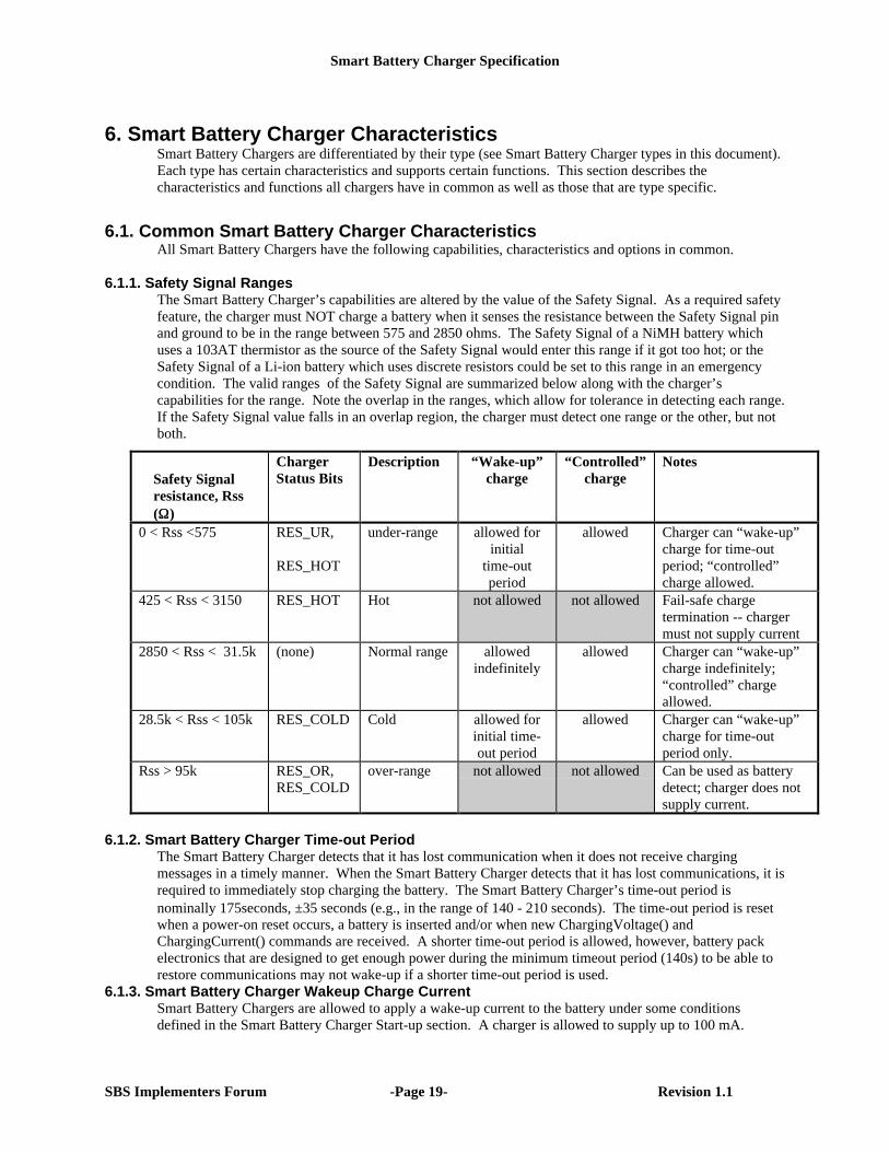
6.1.1. Safety Signal RangesThe Smart Battery Charger’s capabilities are altered by the value of the Safety Signal. As a required safetyfeature, the charger must NOT charge a battery when it senses the resistance between the Safety Signal pinand ground to be in the range between 575 and 2850 ohms. The Safety Signal of a NiMH battery whichuses a 103AT thermistor as the source of the Safety Signal would enter this range if it got too hot; or theSafety Signal of a Li-ion battery which uses discrete resistors could be set to this range in an emergencycondition. The valid ranges of the Safety Signal are summarized below along with the charger’scapabilities for the range. Note the overlap in the ranges, which allow for tolerance in detecting each range.If the Safety Signal value falls in an overlap region, the charger must detect one range or the other, but notboth.
Safety Signalresistance, Rss(ΩΩ)
ChargerStatus Bits
Description “Wake-up”charge
“Controlled”charge
Notes
0 < Rss <575 RES_UR,
RES_HOT
under-range allowed forinitial
time-outperiod
allowed Charger can “wake-up”charge for time-outperiod; “controlled”charge allowed.
425 < Rss < 3150 RES_HOT Hot not allowed not allowed Fail-safe chargetermination -- chargermust not supply current
2850 < Rss < 31.5k (none) Normal range allowedindefinitely
allowed Charger can “wake-up”charge indefinitely;“controlled” chargeallowed.
28.5k < Rss < 105k RES_COLD Cold allowed forinitial time-out period
allowed Charger can “wake-up”charge for time-outperiod only.
Rss > 95k RES_OR,RES_COLD
over-range not allowed not allowed Can be used as batterydetect; charger does notsupply current.
6.1.2. Smart Battery Charger Time-out PeriodThe Smart Battery Charger detects that it has lost communication when it does not receive chargingmessages in a timely manner. When the Smart Battery Charger detects that it has lost communications, it isrequired to immediately stop charging the battery. The Smart Battery Charger’s time-out period isnominally 175seconds, ±35 seconds (e.g., in the range of 140 - 210 seconds). The time-out period is resetwhen a power-on reset occurs, a battery is inserted and/or when new ChargingVoltage() andChargingCurrent() commands are received. A shorter time-out period is allowed, however, battery packelectronics that are designed to get enough power during the minimum timeout period (140s) to be able torestore communications may not wake-up if a shorter time-out period is used.
6.1.3. Smart Battery Charger Wakeup Charge CurrentSmart Battery Chargers are allowed to apply a wake-up current to the battery under some conditionsdefined in the Smart Battery Charger Start-up section. A charger is allowed to supply up to 100 mA.
Smart Battery Charger Specification
SBS Implementers Forum -Page 20- Revision 1.1
6.1.4. Charger Brown-Out ConditionsSituations may arise where the system attempts to charge a battery while the system is also being poweredfrom the AC power supply. In these cases, the charger may not draw so much power that the system’spower source is compromised. The charger can, at its option, choose to charge the battery at a lower rateautomatically or abort charging entirely. The Smart Battery Charger will report when it lowers its outputby setting the ChargerStatus() register’s optional VOLTAGE_NOTREG and CURRENT_NOTREG bits asappropriate.
6.1.5. Smart Battery Charger Leakage CurrentA leakage current may flow between the Smart Battery and the Smart Battery Charger at times when nocurrent flow is expected (e.g. programmed zero charge current, Safety Signal value indicates no chargingallowed, no input power to the charger). Smart Battery Charger manufacturers are expected to minimizeleakage current to prevent unintended over-charging or unintended low-rate discharging which may resultin shortened battery life. Leakage currents should be less than 100uA.
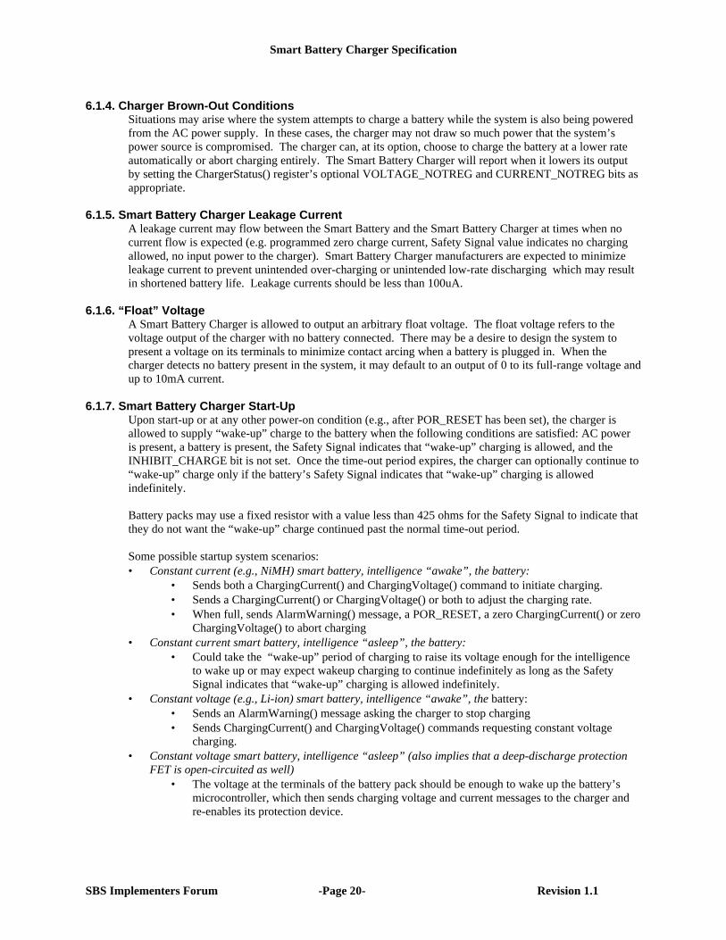
6.1.6. “Float” VoltageA Smart Battery Charger is allowed to output an arbitrary float voltage. The float voltage refers to thevoltage output of the charger with no battery connected. There may be a desire to design the system topresent a voltage on its terminals to minimize contact arcing when a battery is plugged in. When thecharger detects no battery present in the system, it may default to an output of 0 to its full-range voltage andup to 10mA current.
6.1.7. Smart Battery Charger Start-UpUpon start-up or at any other power-on condition (e.g., after POR_RESET has been set), the charger isallowed to supply “wake-up” charge to the battery when the following conditions are satisfied: AC poweris present, a battery is present, the Safety Signal indicates that “wake-up” charging is allowed, and theINHIBIT_CHARGE bit is not set. Once the time-out period expires, the charger can optionally continue to“wake-up” charge only if the battery’s Safety Signal indicates that “wake-up” charging is allowedindefinitely.
Battery packs may use a fixed resistor with a value less than 425 ohms for the Safety Signal to indicate thatthey do not want the “wake-up” charge continued past the normal time-out period.
Some possible startup system scenarios:• Constant current (e.g., NiMH) smart battery, intelligence “awake”, the battery:
• Sends both a ChargingCurrent() and ChargingVoltage() command to initiate charging.• Sends a ChargingCurrent() or ChargingVoltage() or both to adjust the charging rate.• When full, sends AlarmWarning() message, a POR_RESET, a zero ChargingCurrent() or zero
ChargingVoltage() to abort charging• Constant current smart battery, intelligence “asleep”, the battery:
• Could take the “wake-up” period of charging to raise its voltage enough for the intelligenceto wake up or may expect wakeup charging to continue indefinitely as long as the SafetySignal indicates that “wake-up” charging is allowed indefinitely.
• Constant voltage (e.g., Li-ion) smart battery, intelligence “awake”, the battery:• Sends an AlarmWarning() message asking the charger to stop charging• Sends ChargingCurrent() and ChargingVoltage() commands requesting constant voltage
charging.• Constant voltage smart battery, intelligence “asleep” (also implies that a deep-discharge protection
FET is open-circuited as well)• The voltage at the terminals of the battery pack should be enough to wake up the battery’s
microcontroller, which then sends charging voltage and current messages to the charger andre-enables its protection device.
Smart Battery Charger Specification
SBS Implementers Forum -Page 21- Revision 1.1
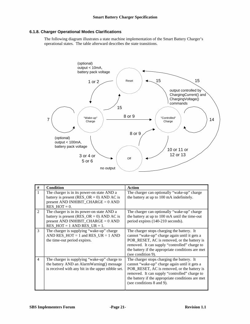
6.1.8. Charger Operational Modes Clarifications
The following diagram illustrates a state machine implementation of the Smart Battery Charger’soperational states. The table afterward describes the state transitions.
Reset
"Wake-up"Charge
Off
"Controlled"Charge
8 or 9
78 or 9
1 or 2
3 or 4 or5 or 6
15 15
14
15
10 or 11 or12 or 13
(optional)output < 10mA,battery pack voltage
(optional)output < 100mA,battery pack voltage
no output
output controlled byChargingCurrent() andChargingVoltage()commands
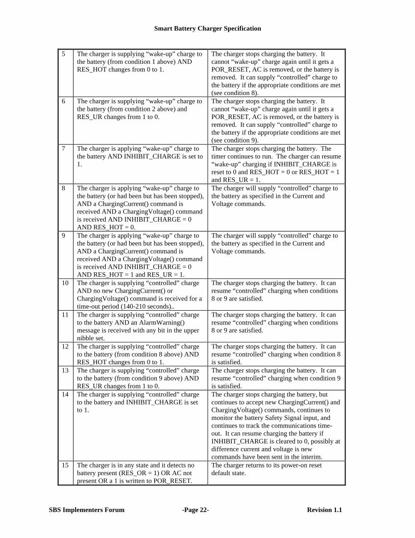
# Condition Action1 The charger is in its power-on state AND a
battery is present (RES_OR = 0) AND AC ispresent AND INHIBIT_CHARGE = 0 ANDRES_HOT = 0.
The charger can optionally “wake-up” chargethe battery at up to 100 mA indefinitely.
2 The charger is in its power-on state AND abattery is present (RES_OR = 0) AND AC ispresent AND INHIBIT_CHARGE = 0 ANDRES_HOT = 1 AND RES_UR = 1.
The charger can optionally “wake-up” chargethe battery at up to 100 mA until the time-outperiod expires (140-210 seconds).
3 The charger is supplying “wake-up” chargeAND RES_HOT = 1 and RES_UR = 1 ANDthe time-out period expires.
The charger stops charging the battery. Itcannot “wake-up” charge again until it gets aPOR_RESET, AC is removed, or the battery isremoved. It can supply “controlled” charge tothe battery if the appropriate conditions are met(see condition 9).
4 The charger is supplying “wake-up” charge tothe battery AND an AlarmWarning() messageis received with any bit in the upper nibble set.
The charger stops charging the battery. Itcannot “wake-up” charge again until it gets aPOR_RESET, AC is removed, or the battery isremoved. It can supply “controlled” charge tothe battery if the appropriate conditions are met(see conditions 8 and 9).
Smart Battery Charger Specification
SBS Implementers Forum -Page 22- Revision 1.1
5 The charger is supplying “wake-up” charge tothe battery (from condition 1 above) ANDRES_HOT changes from 0 to 1.
The charger stops charging the battery. Itcannot “wake-up” charge again until it gets aPOR_RESET, AC is removed, or the battery isremoved. It can supply “controlled” charge tothe battery if the appropriate conditions are met(see condition 8).
6 The charger is supplying “wake-up” charge tothe battery (from condition 2 above) andRES_UR changes from 1 to 0.
The charger stops charging the battery. Itcannot “wake-up” charge again until it gets aPOR_RESET, AC is removed, or the battery isremoved. It can supply “controlled” charge tothe battery if the appropriate conditions are met(see condition 9).
7 The charger is applying “wake-up” charge tothe battery AND INHIBIT_CHARGE is set to1.
The charger stops charging the battery. Thetimer continues to run. The charger can resume“wake-up” charging if INHIBIT_CHARGE isreset to 0 and RES_HOT = 0 or RES_HOT = 1and RES_UR = 1.
8 The charger is applying “wake-up” charge tothe battery (or had been but has been stopped),AND a ChargingCurrent() command isreceived AND a ChargingVoltage() commandis received AND INHIBIT_CHARGE = 0AND RES_HOT = 0.
The charger will supply “controlled” charge tothe battery as specified in the Current andVoltage commands.
9 The charger is applying “wake-up” charge tothe battery (or had been but has been stopped),AND a ChargingCurrent() command isreceived AND a ChargingVoltage() commandis received AND INHIBIT_CHARGE = 0AND RES_HOT = 1 and RES_UR = 1.
The charger will supply “controlled” charge tothe battery as specified in the Current andVoltage commands.
10 The charger is supplying “controlled” chargeAND no new ChargingCurrent() orChargingVoltage() command is received for atime-out period (140-210 seconds)..
The charger stops charging the battery. It canresume “controlled” charging when conditions8 or 9 are satisfied.
11 The charger is supplying “controlled” chargeto the battery AND an AlarmWarning()message is received with any bit in the uppernibble set.
The charger stops charging the battery. It canresume “controlled” charging when conditions8 or 9 are satisfied.
12 The charger is supplying “controlled” chargeto the battery (from condition 8 above) ANDRES_HOT changes from 0 to 1.
The charger stops charging the battery. It canresume “controlled” charging when condition 8is satisfied.
13 The charger is supplying “controlled” chargeto the battery (from condition 9 above) ANDRES_UR changes from 1 to 0.
The charger stops charging the battery. It canresume “controlled” charging when condition 9is satisfied.
14 The charger is supplying “controlled” chargeto the battery and INHIBIT_CHARGE is setto 1.
The charger stops charging the battery, butcontinues to accept new ChargingCurrent() andChargingVoltage() commands, continues tomonitor the battery Safety Signal input, andcontinues to track the communications time-out. It can resume charging the battery ifINHIBIT_CHARGE is cleared to 0, possibly atdifference current and voltage is newcommands have been sent in the interim.
15 The charger is in any state and it detects nobattery present (RES_OR = 1) OR AC notpresent OR a 1 is written to POR_RESET.
The charger returns to its power-on resetdefault state.
Smart Battery Charger Specification
SBS Implementers Forum -Page 23- Revision 1.1
6.1.9. Optional Smart Battery Charger Registers for Selector SupportTo support implementations of a Smart Battery Charger and Smart Battery Selector combined in the samecomponent, optional charger command codes have been defined. These codes are optional and only usedby charger components that also include selector functionality. Their presence is indicated by theSELECTOR_SUPPORT bit in the ChargerSpecInfo() function.
When implemented, the Smart Battery Charger’s SelectorState(), SelectorPresets() and SelectorInfo()functions match the corresponding functions described in the Smart Battery Selector Specification. Themapping of the Smart Battery Selector functions into the Smart Battery Charger’s command codes may beaccomplished by logical OR’ing the desired Smart Battery Selector command code with 0x20 and thensending it to the Smart Battery Charger’s SMBus address. Therefore, for a Smart Battery Charger /Selector component, the function code for SelectorState() is 0x21, for SelectorPresets(), 0x22 and forSelectorInfo(), 0x24. The Smart Battery Charger’s defined optional manufacturer’s extended commandsremain located in the range of 0x3c-3f and both the charger and selector share this area in a dual-functioncomponent.
6.1.10. Optional Charger Interrupt MechanismSmart Battery Chargers may have an optional interrupt mechanism to indicate to the system that a changein its status has taken place, for example, battery insertion or removal or AC present. While thismechanism is optional, its inclusion is highly recommended:• For single-battery systems which do not implement a Smart Battery Selector to indicate changes in the
system’s power status.• For multiple battery systems as a way to notify the Smart Battery Selector that it may automatically
charge the “next” battery.One interrupt mechanism available is the SMBus Alert and AlertResponse protocol defined in the SystemManagement Bus Specification.
6.1.11. Battery Internal Charge ControlChargingCurrent() and ChargingVoltage() requests from the battery may be used to define a charging“envelope” within which a battery may internally charge itself. For example, a battery which pulse chargesitself with the full requested current and voltage from the charger for 80% of the time, and takes no powerduring the remaining 20% of the time while the battery “rests”.
Smart Battery Charger Specification
SBS Implementers Forum -Page 24- Revision 1.1
6.2. Level 2 Smart Battery Charger Characteristics
6.2.1. Required CommandsAlarmWarning()ChargingCurrent()ChargingVoltage()ChargerSpecInfo()ChargerMode()ChargerStatus()
6.2.2. Charge InitiationLevel 2 chargers may initiate charge:• upon insertion of a battery• when charge power becomes available• when ChargingVoltage() and ChargingCurrent() are both set to non-zero values• when the AlarmWarning() is written without critical error bits set.Other methods may be used to determine that charging may be (re)initiated. Charging is not initiated if theSafety Signal indicates that no charging is allowed, if the AlarmWarning() has critical error bits set or wheneither ChargingCurrent() or ChargingVoltage() are set to zero. Voltage and current may default at power-on to the expected open circuit battery voltage and a current ≤10mA.
6.2.3. Charge TerminationLevel 2 chargers will discontinue charging:• when AlarmWarning() is written with critical error bits set• if either ChargingCurrent() or ChargingVoltage() are set to zero• when the Safety Signal indicates that no charging is allowed.Additional methods of charge termination are allowed. Charging may resume when charge initiationconditions in 6.2.2 are met.
6.2.4. Charge Current and VoltageThe maximum charging current and voltage of the Level 2 charger is determined by the Smart Batterymanufacturer and is programmable through the ChargingCurrent() and ChargingVoltage() commands.Default values for these may be zero or any non-zero range determined to be safe for any chemistry(100mA or less). Non-zero default values, if used, must only be enabled when the Safety Signal indicatesthat “controlled” charging is allowed. The default charge current and voltage must not be persistent; anynew value of ChargingCurrrent() or ChargingVoltage() must over-write any default values.
6.3. Level 3 Smart Battery Charger Characteristics
6.3.1. Required CommandsAlarmWarning()ChargingCurrent()ChargingVoltage()ChargerSpecInfo()ChargerMode()ChargerStatus()Note that a Level 3 Smart Battery Charger supports all the commands of a Level 2 charger and differs onlyin the ability to become a SMBus master device and initiate charging directly. When set to the slave devicemode by the ENABLE_POLLING bit not set, the Level 3 charger behaves in all respects as a Level 2charger.
6.3.2. Charge InitiationLevel 3 Smart Battery Chargers may initiate charge under the same conditions as Level 2 chargers andfurther have the ability to initiate charging under program control. When a Level 3 Smart Battery Charger
Smart Battery Charger Specification
SBS Implementers Forum -Page 25- Revision 1.1
initiates polling and therefore charging, it is suggested that the Level 3 Smart Battery Charger disable theautomatic broadcasts of the battery by setting Battery Mode CHARGER_MODE bit. See the SmartBattery Data Specification for details (refer to the References section).
6.3.3. Charge TerminationLike the Level 2 charger, Level 3 Smart Battery Chargers will discontinue charging when anAlarmWarning() is written with critical error bits set, if either ChargingCurrent() or ChargingVoltage() areset to zero, or when the Safety Signal indicates that no charging is allowed. Additional methods of chargetermination are allowed. Charging may resume when charge initiation conditions in 6.3.2 are met.
6.3.4. Charge Current and VoltageThe maximum charging current and voltage of the Level 3 Smart Battery Charger is determined by themanufacturer and is programmable through the ChargingCurrent() and ChargingVoltage() commands.Default values for these may be zero or any non-zero range determined to be safe for any chemistry. Non-zero default values, when used, must only be enabled when the Safety Signal indicates that “controlled”charging is allowed. The default charge current and voltage must not be persistent; any new value ofChargingCurrrent() or ChargingVoltage() must over-write any default values.
Smart Battery Charger Specification
SBS Implementers Forum -Page 26- Revision 1.1
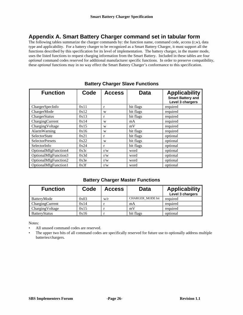
Appendix A. Smart Battery Charger command set in tabular formThe following tables summarize the charger commands by: the function name, command code, access (r,w), datatype and applicability. For a battery charger to be recognized as a Smart Battery Charger, it must support all thefunctions described by this specification for its level of implementation. The battery charger, in the master mode,uses the listed functions to request charging information from the Smart Battery. Included in these tables are fouroptional command codes reserved for additional manufacturer specific functions. In order to preserve compatibility,these optional functions may in no way effect the Smart Battery Charger’s conformance to this specification.
Battery Charger Slave Functions
Function Code Access Data ApplicabilitySmart Battery andLevel 3 chargers
ChargerSpecInfo 0x11 r bit flags requiredChargerMode 0x12 w bit flags requiredChargerStatus 0x13 r bit flags requiredChargingCurrent 0x14 w mA requiredChargingVoltage 0x15 w mV requiredAlarmWarning 0x16 w bit flags requiredSelectorState 0x21 r bit flags optionalSelectorPresets 0x22 w bit flags optionalSelectorInfo 0x24 r bit flags optionalOptionalMfgFunction4 0x3c r/w word optionalOptionalMfgFunction3 0x3d r/w word optionalOptionalMfgFunction2 0x3e r/w word optionalOptionalMfgFunction1 0x3f r/w word optional
Battery Charger Master Functions
Function Code Access Data ApplicabilityLevel 3 chargers
BatteryMode 0x03 w/r CHARGER_MODE bit requiredChargingCurrent 0x14 r mA requiredChargingVoltage 0x15 r mV requiredBatteryStatus 0x16 r bit flags optional
Notes:• All unused command codes are reserved.• The upper two bits of all command codes are specifically reserved for future use to optionally address multiple
batteries/chargers.
Smart Battery Charger Specification
SBS Implementers Forum -Page 27- Revision 1.1
Appendix B. Smart Battery System Safety FeaturesSafety is a primary design goal in the Smart Battery System specifications. The central concept behind theSmart Battery specifications is locating the primary intelligence of the system inside the battery pack itself.This enables the system to be much more accurate in measurement of battery parameters such as remainingcapacity and design voltage, and also allows the charging algorithm and parameters to be tuned to thebattery pack’s specific chemistry. By relying on the battery pack’s intelligence, a properly designed SmartBattery system will safely charge and discharge any expected battery chemistry.
Protection against high rates of discharge is well understood by the battery industry and easily guardedagainst in battery pack design through the use of safety devices such as fuses. However, protection from anover zealous charger is more difficult requiring tight coupling between the charger and battery. The SmartBattery system defines a standard set of messages as well as an independent means for the battery toterminate charge. Correct operation of the charger is key to maintaining safe operation.
This section will review the safety features contained in the Smart Battery specifications. Particularattention will be focused on the following operating modes: , “Wake-up” Charging “Controlled” Charging,and Discharging.
“Wake-up” ChargingIt is possible for a battery pack to be so depleted that its built-in intelligence will not have enough power tooperate. Therefore, the Smart Battery System specifications require a charger to apply some small amountof charge (less than 100mA) to a battery when it is first connected so that it can receive enough power towake up and communicate. This “wake-up” charge may not begin if the Safety Signal indicates that no“wake-up” charging is allowed. The "wake-up" charge will be terminated when the battery sends a criticalmessage to the charger, or the Safety Signal moves into a range in which “wake-up” charging is notallowed, or the “wake-up” charge time-out period expires.
“Controlled” Charging“Controlled” Charging (i.e., charging under battery control) can only be initiated when and if the batteryexplicitly requests charging from the Smart Battery Charger device in the system AND the chargerindependently determines it is safe to do so. Charging will be aborted at any time the battery or chargerdetects an error condition. The battery requests charging when it sends two separate messages to thecharger indicating both its desired ChargingVoltage() and ChargingCurrent(); the charger will attempt tosupply the requested voltage and current if the Safety Signal indicates that “controlled” charging isallowed.. Charging continues as long as new current and voltage messages are sent by the battery to thecharger (to prevent charger from timing out) and the Safety Signal value stays within a range that allows“controlled” charging. Charging MUST be terminated immediately when any of the following conditionsoccur:• a critical message is received by the charger• The charger receives a ChargingCurrent or ChargingVoltage message with a zero value.• the Safety Signal moves out of a range that allows “controlled” charging.• the charger doesn’t receive valid current and voltage messages within the time-out period.
Therefore, to begin charging, both the battery and charger must agree it is safe to do so. First, the batterymust explicitly request charging. If the battery detects some error condition (battery pack voltage too highor low, temperature out of acceptable ranges, individual cell voltage shorted, etc.) it won’t request chargingand charging will never begin. Second, the charger will not begin charging if the Safety Signal indicatesthat no “controlled” charging is allowed.Furthermore, to continue charging, both the battery and charger must be satisfied it is still safe to do so.First, the battery must continuously send messages to the charger indicating its requested charging currentand voltage. If any error condition occurs in the battery, the battery will send a message to the charger toterminate charge. Or, the battery can simply stop sending messages to the charger and charging will stopafter the charger detects the battery is no longer sending out messages. (For the same reason, the chargerwill stop charging if something happens to the communications channel between the battery and charger,
Smart Battery Charger Specification
SBS Implementers Forum -Page 28- Revision 1.1
since it will no longer be receiving messages from the battery.) Second, the charger will monitor thebattery pack Safety Signal terminal. If the Safety Signal moves out of a range that allows “controlled”charging, the charger will immediately terminate charge. This could happen if the temperature of thebattery pack got too hot, or the intelligence in the pack could force the Safety Signal to that range toindicate an error condition and abort charging immediately.
These mechanisms are independent of and in addition to any protection mechanisms in the battery packitself, for example, fuses or protection FETs controlled by hard-wired safety circuitry.
DischargingThe Smart Battery System specifications also have a mechanism for the battery to request that the systemstop discharging it. If the battery detects that it no longer wishes to be discharged, it can send a high-priority message to the system asking it to stop drawing power from it. The system should process themessages and switch to another power source if available, or go into a low-power state if not. However,there is no hardware mechanism to enforce the battery’s desire to stop providing power through itsterminals.
Smart Battery Charger Specification
SBS Implementers Forum -Page 29- Revision 1.1
Appendix C. Smart Battery Alarm Bits
Alarm BitsOVER_CHARGED_ALARM bit is set whenever the Smart Battery detects that it is being chargedbeyond an end-of-charge indication. This bit will be cleared when the Smart Battery detects that it is nolonger being over-charged.TERMINATE_CHARGE_ALARM bit is set when the Smart Battery detects that one or more of itscharging parameters are out of range (e.g. its voltage or current are too high). This bit will be cleared whenthe parameter falls back in into the allowable range. Failure to correct the problem may result in permanentdamage to the battery.OVER_TEMP_ALARM bit will be set when the Smart Battery detects that its internal temperature isgreater than allowed. This bit will be cleared when the internal temperature falls back into the acceptablerange.TERMINATE_DISCHARGE_ALARM bit is set when the Smart Battery determines that it has suppliedall the charge it can without being damaged (i.e., continued use will result in permanent capacity loss to thebattery). This bit will be cleared when the battery reaches a state-of-charge sufficient for it to once againsafely supply power.
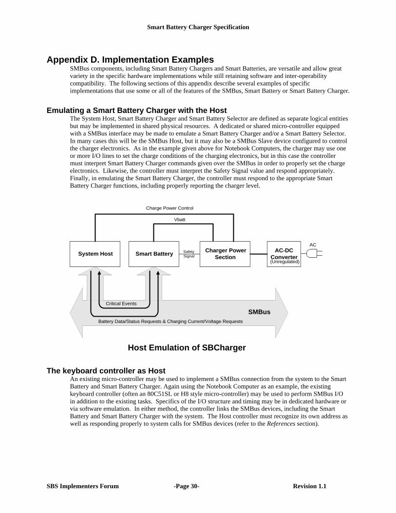
Smart Battery Charger Specification
SBS Implementers Forum -Page 30- Revision 1.1
Appendix D. Implementation ExamplesSMBus components, including Smart Battery Chargers and Smart Batteries, are versatile and allow greatvariety in the specific hardware implementations while still retaining software and inter-operabilitycompatibility. The following sections of this appendix describe several examples of specificimplementations that use some or all of the features of the SMBus, Smart Battery or Smart Battery Charger.
Emulating a Smart Battery Charger with the HostThe System Host, Smart Battery Charger and Smart Battery Selector are defined as separate logical entitiesbut may be implemented in shared physical resources. A dedicated or shared micro-controller equippedwith a SMBus interface may be made to emulate a Smart Battery Charger and/or a Smart Battery Selector.In many cases this will be the SMBus Host, but it may also be a SMBus Slave device configured to controlthe charger electronics. As in the example given above for Notebook Computers, the charger may use oneor more I/O lines to set the charge conditions of the charging electronics, but in this case the controllermust interpret Smart Battery Charger commands given over the SMBus in order to properly set the chargeelectronics. Likewise, the controller must interpret the Safety Signal value and respond appropriately.Finally, in emulating the Smart Battery Charger, the controller must respond to the appropriate SmartBattery Charger functions, including properly reporting the charger level.
System HostCharger Power
SectionSmart Battery
Vbatt
Critical Events
Battery Data/Status Requests & Charging Current/Voltage Requests
SMBus
AC-DCConverter
ACSafetySignal
Host Emulation of SBCharger
(Unregulated)
Charge Power Control
The keyboard controller as HostAn existing micro-controller may be used to implement a SMBus connection from the system to the SmartBattery and Smart Battery Charger. Again using the Notebook Computer as an example, the existingkeyboard controller (often an 80C51SL or H8 style micro-controller) may be used to perform SMBus I/Oin addition to the existing tasks. Specifics of the I/O structure and timing may be in dedicated hardware orvia software emulation. In either method, the controller links the SMBus devices, including the SmartBattery and Smart Battery Charger with the system. The Host controller must recognize its own address aswell as responding properly to system calls for SMBus devices (refer to the References section).
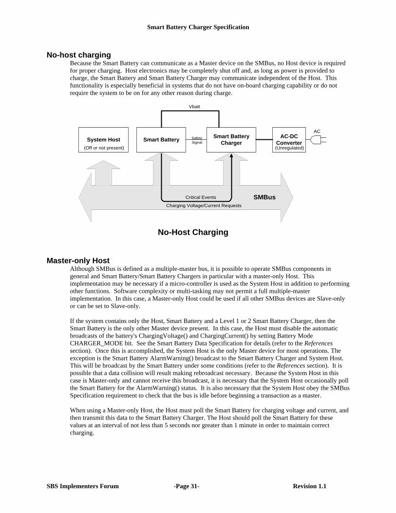
Smart Battery Charger Specification
SBS Implementers Forum -Page 31- Revision 1.1
No-host chargingBecause the Smart Battery can communicate as a Master device on the SMBus, no Host device is requiredfor proper charging. Host electronics may be completely shut off and, as long as power is provided tocharge, the Smart Battery and Smart Battery Charger may communicate independent of the Host. Thisfunctionality is especially beneficial in systems that do not have on-board charging capability or do notrequire the system to be on for any other reason during charge.
System HostSmart Battery
ChargerSmart Battery
Vbatt
Charging Voltage/Current Requests
SMBusCritical Events
AC-DCConverter
ACSafetySignal
No-Host Charging
(Unregulated)(Off or not present)
Master-only HostAlthough SMBus is defined as a multiple-master bus, it is possible to operate SMBus components ingeneral and Smart Battery/Smart Battery Chargers in particular with a master-only Host. Thisimplementation may be necessary if a micro-controller is used as the System Host in addition to performingother functions. Software complexity or multi-tasking may not permit a full multiple-masterimplementation. In this case, a Master-only Host could be used if all other SMBus devices are Slave-onlyor can be set to Slave-only.
If the system contains only the Host, Smart Battery and a Level 1 or 2 Smart Battery Charger, then theSmart Battery is the only other Master device present. In this case, the Host must disable the automaticbroadcasts of the battery's ChargingVoltage() and ChargingCurrent() by setting Battery ModeCHARGER_MODE bit. See the Smart Battery Data Specification for details (refer to the Referencessection). Once this is accomplished, the System Host is the only Master device for most operations. Theexception is the Smart Battery AlarmWarning() broadcast to the Smart Battery Charger and System Host.This will be broadcast by the Smart Battery under some conditions (refer to the References section). It ispossible that a data collision will result making rebroadcast necessary. Because the System Host in thiscase is Master-only and cannot receive this broadcast, it is necessary that the System Host occasionally pollthe Smart Battery for the AlarmWarning() status. It is also necessary that the System Host obey the SMBusSpecification requirement to check that the bus is idle before beginning a transaction as a master.
When using a Master-only Host, the Host must poll the Smart Battery for charging voltage and current, andthen transmit this data to the Smart Battery Charger. The Host should poll the Smart Battery for thesevalues at an interval of not less than 5 seconds nor greater than 1 minute in order to maintain correctcharging.
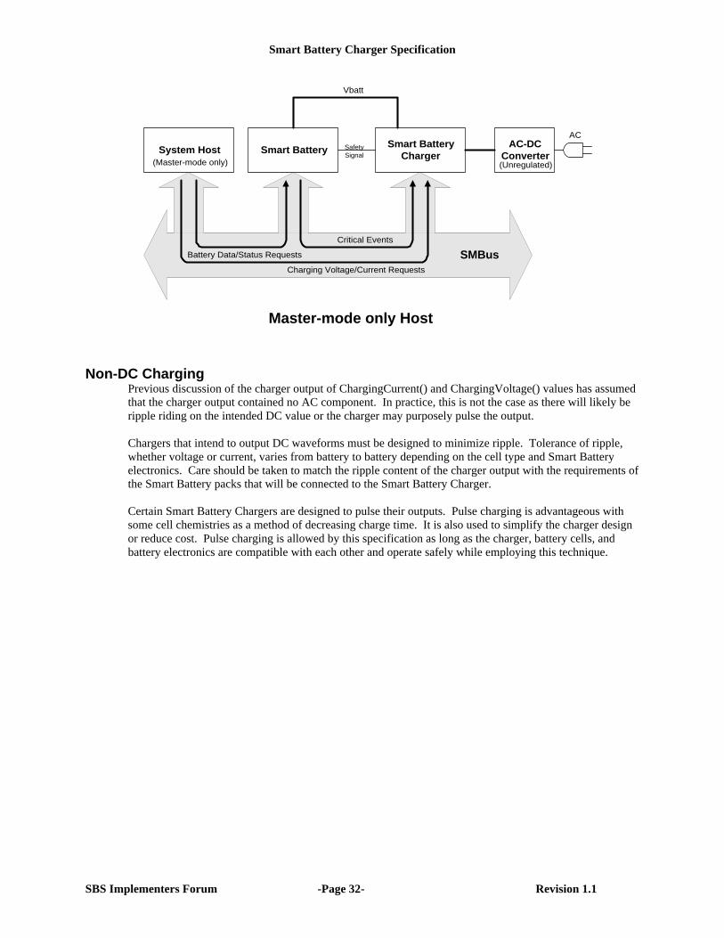
Smart Battery Charger Specification
SBS Implementers Forum -Page 32- Revision 1.1
System HostSmart Battery
ChargerSmart Battery
Vbatt
Charging Voltage/Current Requests
Battery Data/Status Requests SMBusCritical Events
AC-DCConverter
ACSafetySignal
Master-mode only Host
(Unregulated)(Master-mode only)
Non-DC ChargingPrevious discussion of the charger output of ChargingCurrent() and ChargingVoltage() values has assumedthat the charger output contained no AC component. In practice, this is not the case as there will likely beripple riding on the intended DC value or the charger may purposely pulse the output.
Chargers that intend to output DC waveforms must be designed to minimize ripple. Tolerance of ripple,whether voltage or current, varies from battery to battery depending on the cell type and Smart Batteryelectronics. Care should be taken to match the ripple content of the charger output with the requirements ofthe Smart Battery packs that will be connected to the Smart Battery Charger.
Certain Smart Battery Chargers are designed to pulse their outputs. Pulse charging is advantageous withsome cell chemistries as a method of decreasing charge time. It is also used to simplify the charger designor reduce cost. Pulse charging is allowed by this specification as long as the charger, battery cells, andbattery electronics are compatible with each other and operate safely while employing this technique.
Smart Battery Charger Specification
SBS Implementers Forum -Page 33- Revision 1.1
Appendix E. Accuracy Requirements
This specification places minimum accuracy requirements for ChargingCurrent() and ChargingVoltage() onall Smart Battery Chargers to ensure basic operability between SBS system components. The body of thespecification is purposely kept generic with regard to cell chemistry, pack voltage, pack capacity in keepingwith the scope defined in Section 1.1. This appendix will discuss requirements for higher accuracy thanspecified in sections 5.11, 5.12, 5.21 and 5.22.
There are basically two alternatives for optimizing the charger output as required by the particular systemor cell chemistry. The first is to improve the accuracy of the charger output in response to the values in theChargingCurrent() and ChargingVoltage() functions. This follows the traditional route of requiring thecharger to include precision reference, gain and control circuits, which add cost to the charger. The secondalternative is to re-use the battery’s precision circuitry and take advantage of the battery electronics closephysical proximity to the cells to tune the charger output in a closed loop fashion over the SMBus. Thissecond method is encouraged because it reduces system cost, and enables the system to be less dependenton the cell chemistry and pack configuration.
Charging with an Accurate ChargerIncreased charger output accuracy may be required on some systems to maximize stored charge whileensuring safety, as is dictated by aspects of particular cell chemistries. Lithium Ion cell chemistry is a casein point where tight tolerances on minimum charging voltage in the constant voltage phase allow morecharge to be stored in a cell, thus increasing capacity. At the same time, the maximum charge voltage mustbe limited to maintain safe and reliable operation.
Lithium Ion cell manufacturers frequently recommend charging with +/-100mV per cell accuracy, or +/-50mV per cell accuracy. If the charger alone is responsible for maintaining the accuracy of its output, thenit will need to regulate with much more accurately than the +1%/-9% tolerance on ChargingVoltage() thatthe specification requires. In such cases, the ChargingVoltage() accuracy should meet both the +1%/-9%minimum accuracy and the cell manufacturer’s recommendations. For example, charger with aprogrammatic maximum of 17.0V would be required to have +1%/-3.7% accuracy to meet the +/-100mVper cell recommendation on a 4 series cell pack, and +1/-2.3% for a 3 series cell pack. The same 17.0Vcharger would need +1%/-1.3% to meet the +/-50mV recommendation on a 4 cell pack and +/-0.8% on a 3cell pack.
Charging with and Accurate SystemAmong the many benefits of Smart Battery Chargers and the Smart Battery model in general is the lowsystem cost that results from not duplicating costly measurement and control components. A Smart Batteryalready contains A/D conversion and other measurement electronics of sufficient accuracy to provide stateof charge, remaining capacity and other information for that battery. It is not necessary to duplicate thismeasurement capability at the charger, nor is required to exceed or even meet the level of accuracy internalto the Smart Battery, because the battery already contains a sophisticated measurement system and amethod of communicating with the Smart Battery Charger (SMBus).
The Smart Battery has everything necessary to ‘close the loop’ around the Smart Battery Charger andtherefore control the accuracy of the charging voltage and current. For this reason, the Smart BatteryCharger is not expected to be as accurate or precise as the Smart Battery. Even the accuracy of the SafetySignal inputs is regarded as that necessary only for safe charging, not so accurate as to optimize charging.Under normal conditions the Smart Battery electronics are in the best physical location to measure internalvoltages, currents and temperatures to optimize charging.
For these reasons, the data provided by the Smart Battery to the Smart Battery Charger is expected to bemore accurate and of higher resolution than the Smart Battery Charger may be able to provide. If the
Smart Battery Charger Specification
SBS Implementers Forum -Page 34- Revision 1.1
resulting charge condition is unsuitable, the Smart Battery could send new values to the Smart BatteryCharger as in the following example:1. The Smart Battery sets the ChargingCurrent() of the Smart Battery Charger to 1A2. The Smart Battery Charger responds by providing 0.95A, within its ±5% accuracy requirement.3. The Smart Battery measures the charge current of 0.95A and calculates a new target of 1A/0.95A =
1.052A and set the ChargingCurrent() of the Smart Battery Charger to this value to correct the chargecurrent
4. The Smart Battery Charger responds by increasing the output current proportionally, to 1A.5. The Smart Battery accepts this as the final charge current.
The Smart Battery could likewise set the ChargingVoltage() in the same fashion. Note that the decision to“close the loop” is made by the Smart Battery’s manufacturer based upon the needs of the battery. There isno additional requirement placed in the Smart Battery Charger or System Host.
NOTE: Safety factors must be a prime consideration when developing open loop or closed-loopcharging algorithms as described here. Since batteries pose a significant potential risk of fire and/orexplosion, the system designer must carefully match charger output accuracy to the charge profilerequired by the cell types and pack configurations that may be used by a given system.
###