engineering surveying (221 be) theodolite & total … & total... · theodolite & total...
TRANSCRIPT

Theodolite & Total StationSr Tan Liat Choon
Email: [email protected]: 016-4975551
ENGINEERING SURVEYING (221 BE)
Introduction Until recently, transits and theodolites were the most
commonly used surveying instruments for angle measurements for angle measurement. These two devices were fundamentally equivalent and could accomplish basically the same task
Today, total station accomplish all the task much more efficiently than transits and theodolite
In addition, it can observes distance accurately and quickly
Furthermore, it can make computations with the angle and distance measurements and display the result in real time
It is used for all types of surveys including topographic, hidrographic, cadastral, and construction surveys
Transit and Theodolite
Primary function is the accurate measurement of layout of horizontal and vertical angles
Other function • Determining horizontal and vertical
distances by stadia• Extending straight lines• Differential levelling
Definition
Transits and theodolites operate on the same basic principles
No universally accepted difference between the terms “transit” and “theodolite”
Distinguishing characteristics:• Transits have an open design where the measurements are
made by reading verniers on metal circles• Theodlites have a closed designed where the measurements are
made by reading verniers etched on glass circles• Theodolites are capable of greater precision and accuracy
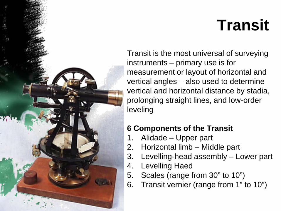
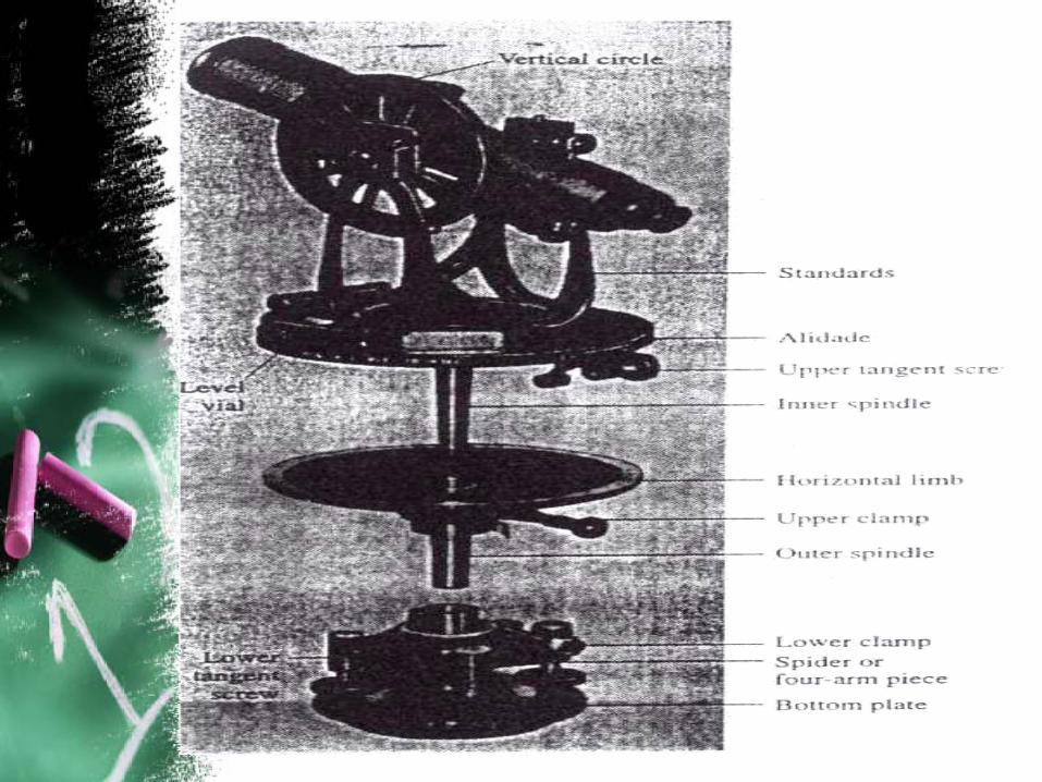
TransitTransit is the most universal of surveying instruments – primary use is for measurement or layout of horizontal and vertical angles – also used to determine vertical and horizontal distance by stadia, prolonging straight lines, and low-order leveling
6 Components of the Transit1. Alidade – Upper part2. Horizontal limb – Middle part3. Levelling-head assembly – Lower part4. Levelling Haed5. Scales (range from 30” to 10”)6. Transit vernier (range from 1” to 10”)
Theodolite
The theodolite is used to measure horizontal and vertical angles for exact survey work
Compared to transit, theodolite are:
• Compact• Lightweight• More accuracy and precise
Transits are more common in the U.S. but are being replaced by theodolite
Type of Theodolite
Repaeting theodolite
Directional Theodolite
Electrical Digital Theodolite
Total Station
Repeating Theodolite
This design enables horizontal angles to be repeated any number of times and added directly on the instrument circles
Advantages of this design are:
• Better accuracy obtained through averaging• Disclosure of errors and mistakes by computing
values of the single and multiple readings
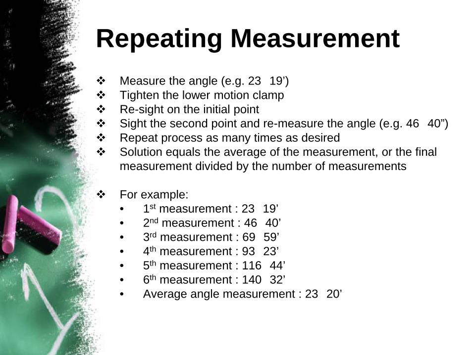
Repeating Measurement Measure the angle (e.g. 23 19’) Tighten the lower motion clamp Re-sight on the initial point Sight the second point and re-measure the angle (e.g. 46 40”) Repeat process as many times as desired Solution equals the average of the measurement, or the final
measurement divided by the number of measurements
For example:• 1st measurement : 23 19’• 2nd measurement : 46 40’• 3rd measurement : 69 59’• 4th measurement : 93 23’• 5th measurement : 116 44’• 6th measurement : 140 32’• Average angle measurement : 23 20’
Directional Theodolite
Non-repeating instrument that has no lower motion
Reads “directions” rather than angles
Angles are obtained by subtracting the first direction reading from the second direction reading
Directional Measurement
Set up the theodolite
Sight the initial point and read the direction (e.g. 31 19’ 27”)
Sight the second point and read the direction (e.g. 85 24’ 49”)
The angle is then calculated as the difference between the two directions (e.g. 54 05’ 22”)
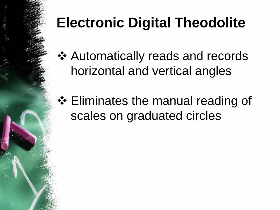
Electronic Digital Theodolite
Automatically reads and records horizontal and vertical angles
Eliminates the manual reading of scales on graduated circles
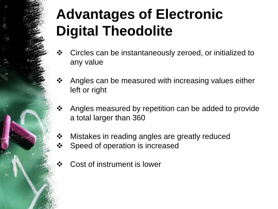
Advantages of Electronic Digital Theodolite Circles can be instantaneously zeroed, or initialized to
any value
Angles can be measured with increasing values either left or right
Angles measured by repetition can be added to provide a total larger than 360
Mistakes in reading angles are greatly reduced Speed of operation is increased
Cost of instrument is lower
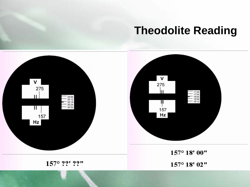
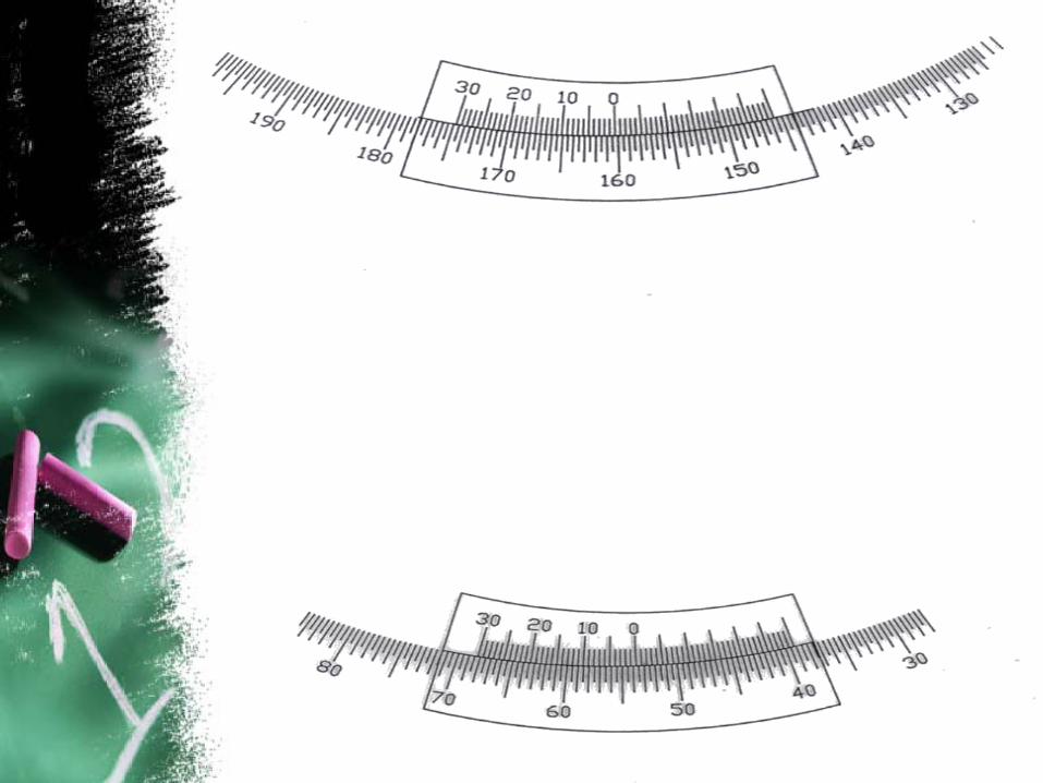
Theodolite Reading
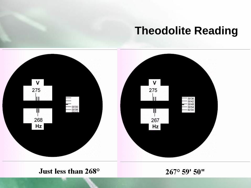
Theodolite Reading
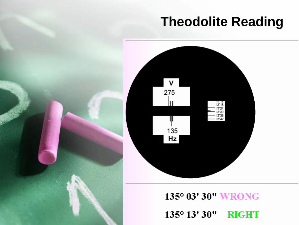
Theodolite Reading
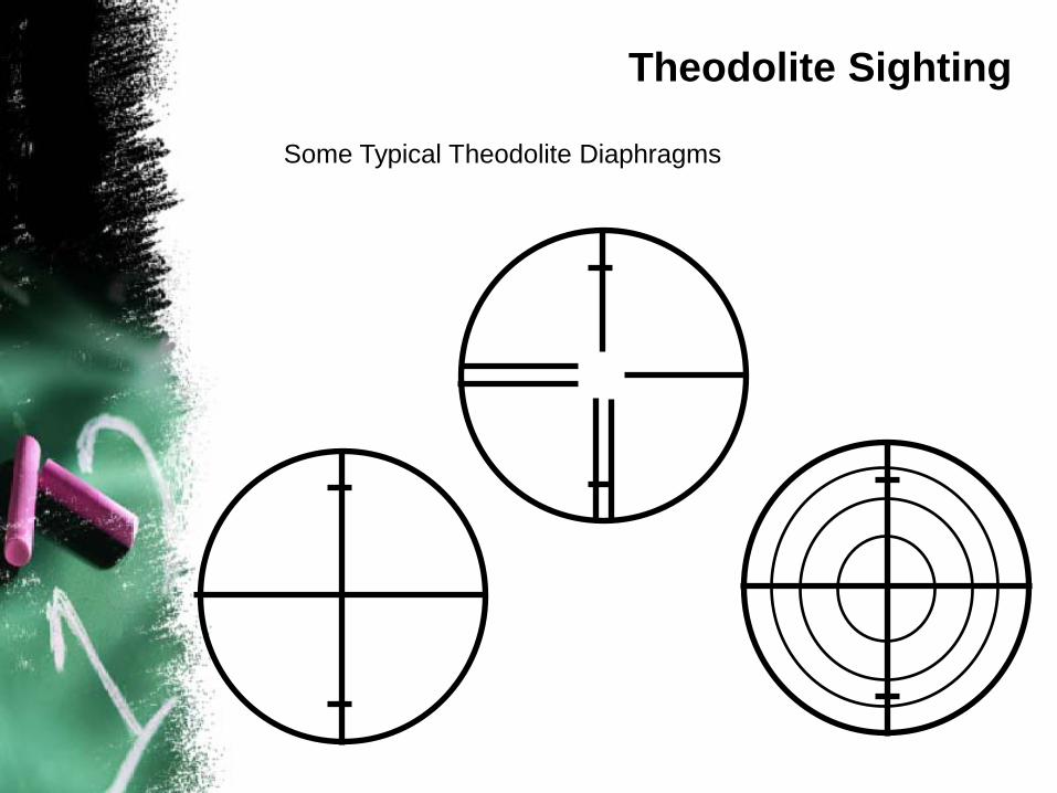
Some Typical Theodolite Diaphragms
Theodolite Sighting
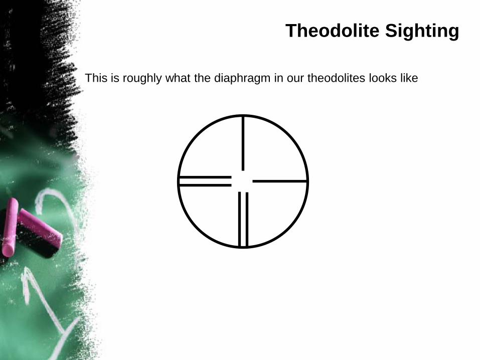
This is roughly what the diaphragm in our theodolites looks like
Theodolite Sighting
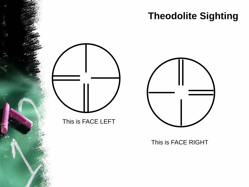
This is FACE LEFT
This is FACE RIGHT
Theodolite Sighting
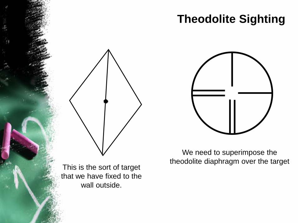
This is the sort of target that we have fixed to the
wall outside.
We need to superimpose the theodolite diaphragm over the target
Theodolite Sighting
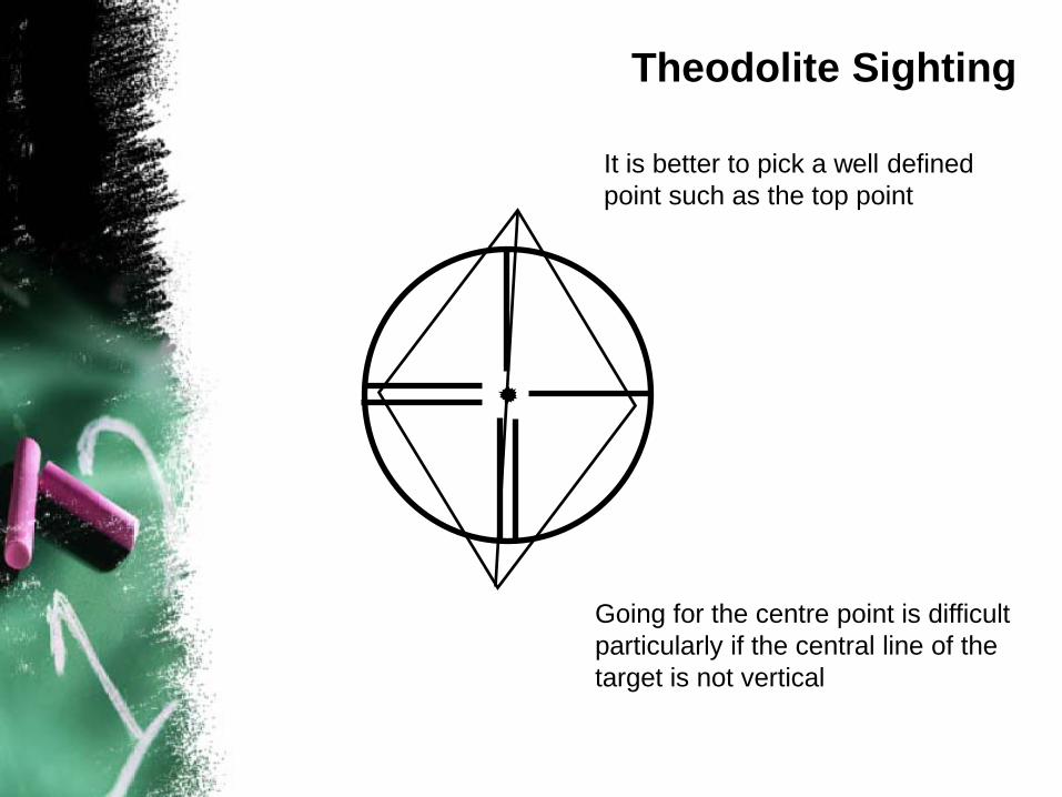
Going for the centre point is difficult particularly if the central line of the target is not vertical
It is better to pick a well defined point such as the top point
Theodolite Sighting
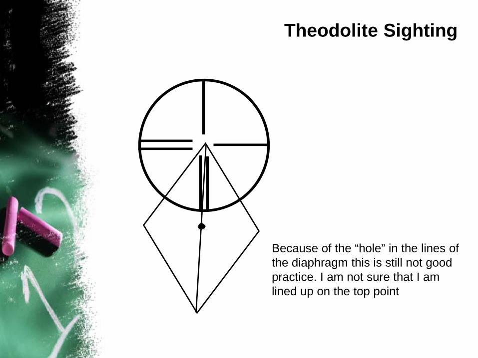
Because of the “hole” in the lines of the diaphragm this is still not good practice. I am not sure that I am lined up on the top point
Theodolite Sighting
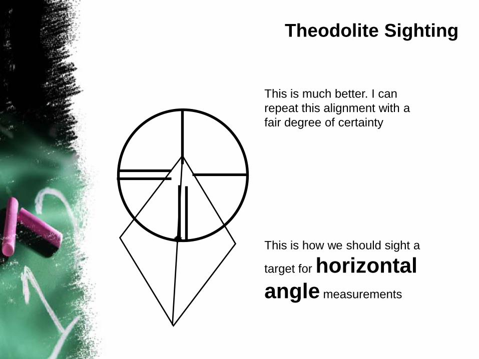
This is much better. I can repeat this alignment with a fair degree of certainty
This is how we should sight a
target for horizontal angle measurements
Theodolite Sighting
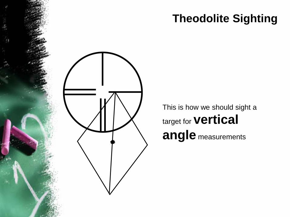
This is how we should sight a
target for vertical angle measurements
Theodolite Sighting
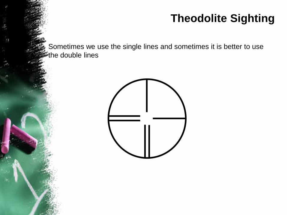
Sometimes we use the single lines and sometimes it is better to use the double lines
Theodolite Sighting
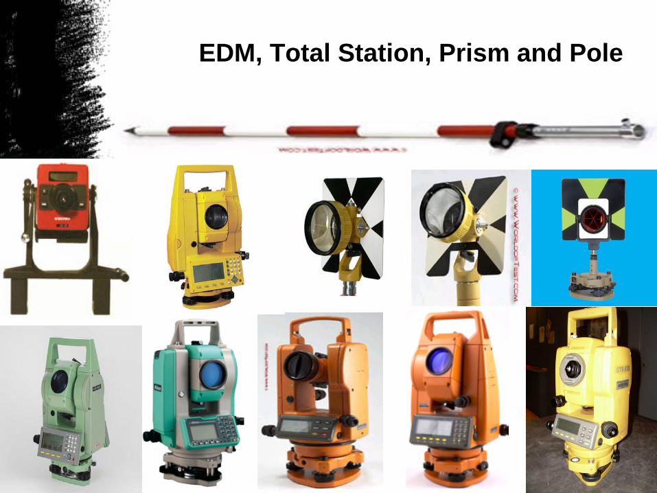
EDM, Total Station, Prism and Pole
Electromagnetic Distance Measurement (EDM)
A major advance in surveying instrument occurred approximately 60 years ago with the development of electronic distance measurement (EDM) instruments. These devices measure lengths by indirectly determining the number of full and partial waves of transmitted, electromagnetic energy required in traveling between the two ends of a line. In practice, the energy is transmitted from one end of the line to the other and returned to the starting points
Electromagnetic Distance Measurement (EDM)
Definition
The electronic distance measurement instrument (EDM) is a relatively new development in the field of surveying. The instrument sends out a beam of light or high frequency microwaves from one end of line to be measured, and directs it towards the far end of the line. A reflector or transmitter receiver at the far end reflects the light or microwaves back to the instrument where they are analyzed electronically to give the distance between the two points
(Francis, 1982)
Electromagnetic Distance Measurement (EDM)
EDM instruments are available to measure distance using light and radio waves. The distance is calculated either from the time difference between a transmitted pulse and a return pulse or the phase difference between a transmitted and a reflected beam of radiation
Electromagnetic Distance Measurement (EDM)
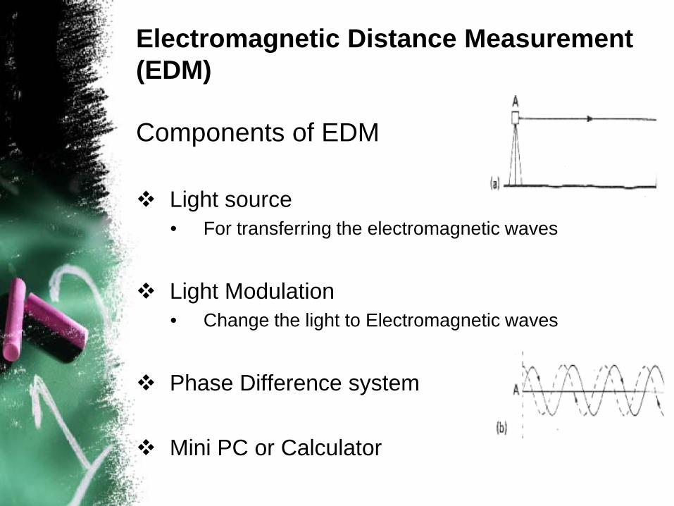
Components of EDM
Light source• For transferring the electromagnetic waves
Light Modulation• Change the light to Electromagnetic waves
Phase Difference system
Mini PC or Calculator
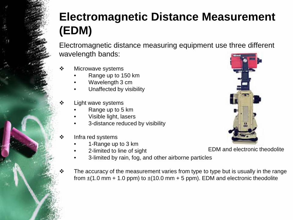
Electromagnetic Distance Measurement (EDM)Electromagnetic distance measuring equipment use three different wavelength bands:
Microwave systems• Range up to 150 km• Wavelength 3 cm• Unaffected by visibility
Light wave systems• Range up to 5 km • Visible light, lasers• 3-distance reduced by visibility
Infra red systems• 1-Range up to 3 km• 2-limited to line of sight• 3-limited by rain, fog, and other airborne particles
The accuracy of the measurement varies from type to type but is usually in the range from ±(1.0 mm + 1.0 ppm) to ±(10.0 mm + 5 ppm). EDM and electronic theodolite
EDM and electronic theodolite
Electromagnetic Distance Measurement (EDM)
Total Station
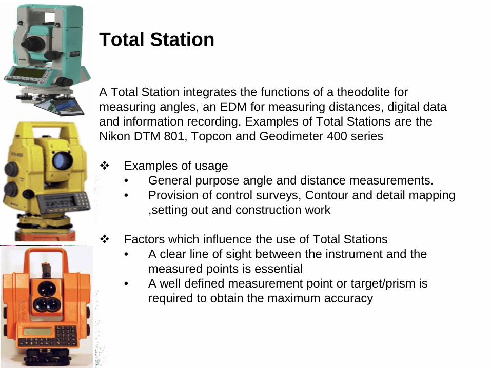
A Total Station integrates the functions of a theodolite for measuring angles, an EDM for measuring distances, digital data and information recording. Examples of Total Stations are the Nikon DTM 801, Topcon and Geodimeter 400 series
Examples of usage • General purpose angle and distance measurements. • Provision of control surveys, Contour and detail mapping
,setting out and construction work
Factors which influence the use of Total Stations• A clear line of sight between the instrument and the
measured points is essential• A well defined measurement point or target/prism is
required to obtain the maximum accuracy
Total Station
Total Station Instrument
An electronic digital theodolite and an electronic distance measurement in one integral unit
They can automatically record horizontal and vertical angles and slope distances from a single setup
Slope distance can be reduced to horizontal and vertical components instantaneously
Given initial data they will display positions and elevations of sighted points
Three Basic Components
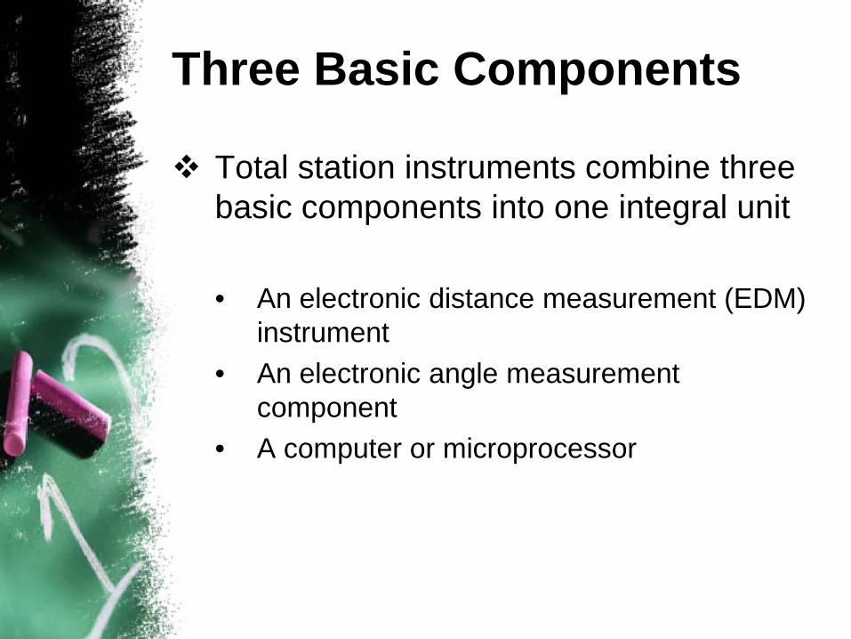
Total station instruments combine three basic components into one integral unit
• An electronic distance measurement (EDM) instrument
• An electronic angle measurement component
• A computer or microprocessor
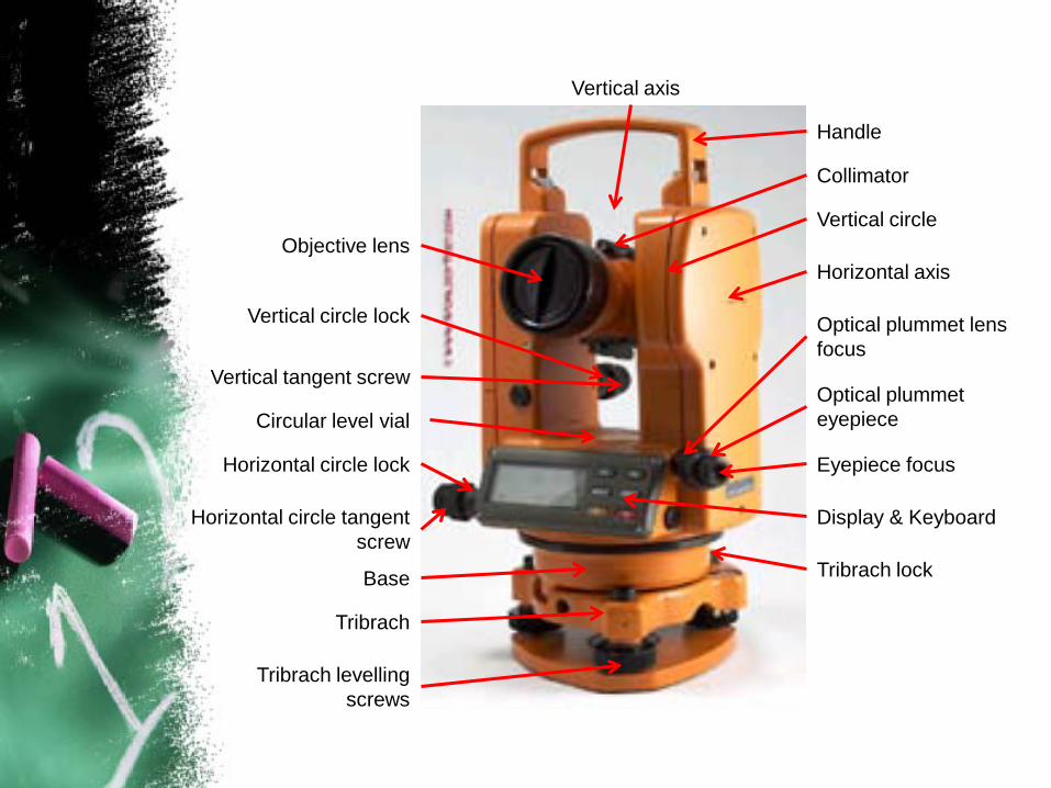
Vertical axis
Collimator
Optical plummet lens focus
Optical plummet eyepiece
Eyepiece focus
Display & Keyboard
Tribrach lock
Tribrach levelling screws
Tribrach
Base
Horizontal circle tangent screw
Horizontal circle lock
Vertical tangent screw
Vertical circle lock
Objective lens
Handle
Vertical circle
Horizontal axis
Circular level vial
Features
Automatically observe• Horizontal and vertical angles• Slope distances from a single set up
Instantaneously compute• Horizontal and vertical distance components• Elevations• Coordinates of the point sighted
Display the result on liquid crystal display (LCD)• Store the data, either on board or in external data
collectors connected to their communication ports
Features
The EDM instruments that are integrated into the total station instruments, lengths up to about 4km which is adequate for most job
Total station instruments are manufactured with two graduated circles, mounted in mutually perpendicular planes• Its horizontal circle is oriented in a horizontal plane, which
automatically puts the vertical circle in a vertical plane• Horizontal and vertical angles can then be measured
directly in their respective planes
Averaging of multiple angles and distance measurements
Correcting electronically measured distances for prism constants, atmospheric pressure and temperature
Features
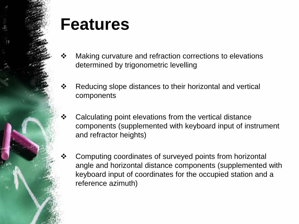
Making curvature and refraction corrections to elevations determined by trigonometric levelling
Reducing slope distances to their horizontal and vertical components
Calculating point elevations from the vertical distance components (supplemented with keyboard input of instrument and refractor heights)
Computing coordinates of surveyed points from horizontal angle and horizontal distance components (supplemented with keyboard input of coordinates for the occupied station and a reference azimuth)
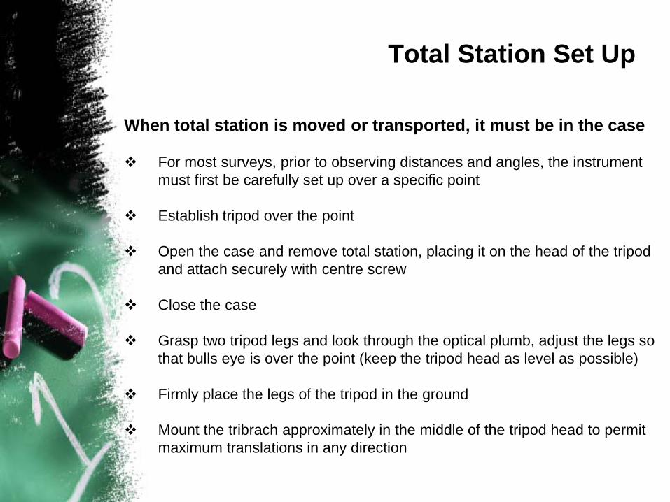
When total station is moved or transported, it must be in the case
For most surveys, prior to observing distances and angles, the instrument must first be carefully set up over a specific point
Establish tripod over the point
Open the case and remove total station, placing it on the head of the tripod and attach securely with centre screw
Close the case
Grasp two tripod legs and look through the optical plumb, adjust the legs so that bulls eye is over the point (keep the tripod head as level as possible)
Firmly place the legs of the tripod in the ground
Mount the tribrach approximately in the middle of the tripod head to permit maximum translations in any direction
Total Station Set Up
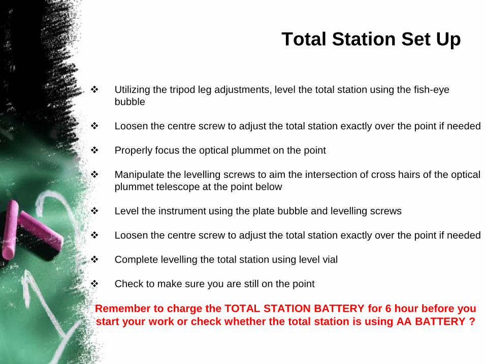
Utilizing the tripod leg adjustments, level the total station using the fish-eye bubble
Loosen the centre screw to adjust the total station exactly over the point if needed
Properly focus the optical plummet on the point
Manipulate the levelling screws to aim the intersection of cross hairs of the optical plummet telescope at the point below
Level the instrument using the plate bubble and levelling screws
Loosen the centre screw to adjust the total station exactly over the point if needed
Complete levelling the total station using level vial
Check to make sure you are still on the point
Remember to charge the TOTAL STATION BATTERY for 6 hour before you start your work or check whether the total station is using AA BATTERY ?
Total Station Set Up
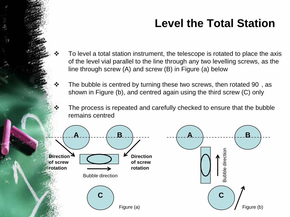
To level a total station instrument, the telescope is rotated to place the axis of the level vial parallel to the line through any two levelling screws, as the line through screw (A) and screw (B) in Figure (a) below
The bubble is centred by turning these two screws, then rotated 90 , as shown in Figure (b), and centred again using the third screw (C) only
The process is repeated and carefully checked to ensure that the bubble remains centred
Level the Total Station
A B
C
A B
C
Bubble direction
Direction of screw rotation
Direction of screw rotation
Figure (a) Figure (b)
Bub
ble
dire
ctio
n
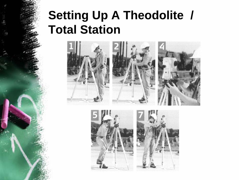
Setting Up A Theodolite / Total Station
Turning Angles With Total Station
Sight on the backsight utilizing the horizontal adjustment screw
Zero set the instrument (this provides an initial reading of 0 seconds)
Loosen tangent screw and rotate instrument to foresight
Tighten tangent screw and bring cross hair exact on target with adjustment screw
Read and record angle as displayed
To close the horizon:• Sight on foresight point from above and zero set instrument• Rotate to former backsight and adjust instrument to exact• Read and record angle as displayed
Angle from direct and indirect should equal 360 degrees
Total Station Distance Measurement
Point the instrument at a prism (which is vertical over the point)
Push the measure button and record the distance
You can measure the horizontal distance or the slope distance, it is important that you note which is being collected
• If you are measuring the slope distance, the zenith angle must be recorded to allow the horizontal distance to be computed
• If you are collecting topographic data with elevations, it is important that the height of the instrument and the height of the prism be collected and recorded
• This can also be solved by setting the prism height the same as the instrument height
Total Station Rules
When moving between setups in the field, proper care should be taken
Before the total station is removed from the tripod, the food screw should be returned to the midpoints of the posts
The instrument should never be transported on the tripod
With adjustable leg tripods, stress on the legs can be avoided by retracting them to their shortest positions and lightly clamping them in position
When returning the total station to its case, all locking mechanisms should be released
If the instrument is wet, it should be wiped down and left in an open case it is dry
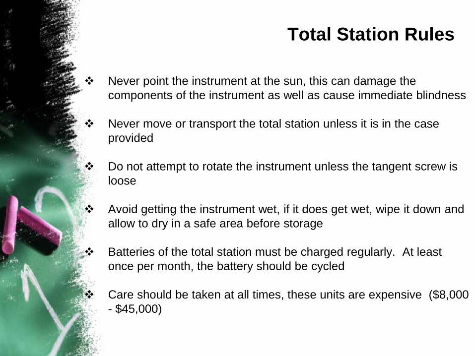
Total Station Rules
Never point the instrument at the sun, this can damage the components of the instrument as well as cause immediate blindness
Never move or transport the total station unless it is in the case provided
Do not attempt to rotate the instrument unless the tangent screw is loose
Avoid getting the instrument wet, if it does get wet, wipe it down and allow to dry in a safe area before storage
Batteries of the total station must be charged regularly. At least once per month, the battery should be cycled
Care should be taken at all times, these units are expensive ($8,000 - $45,000)
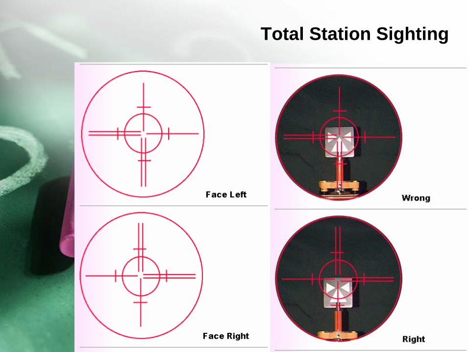
Total Station Sighting
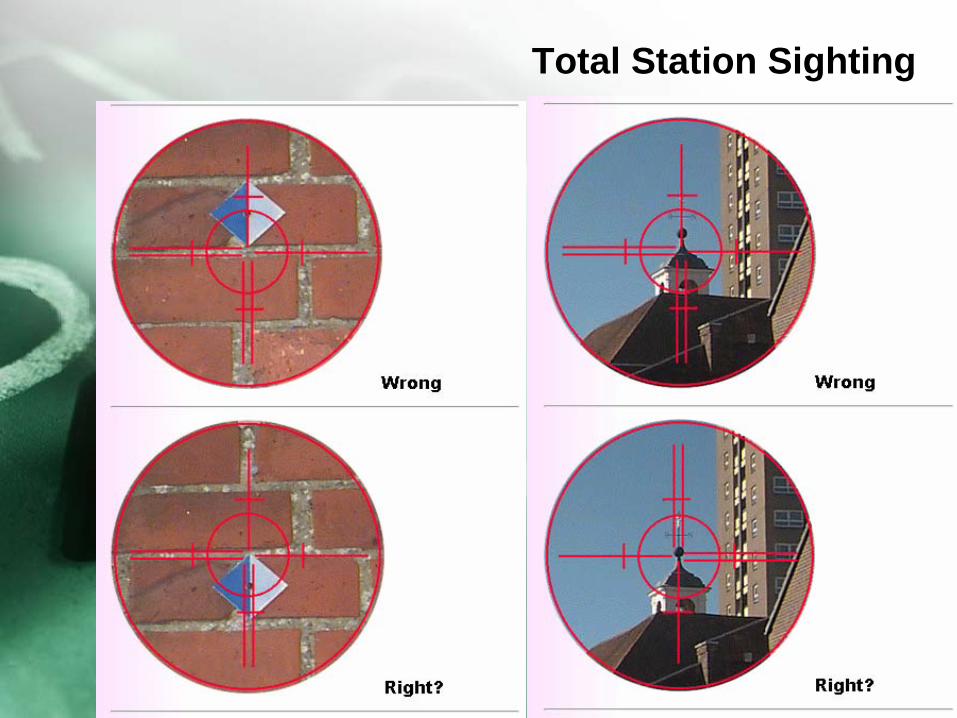
Total Station Sighting
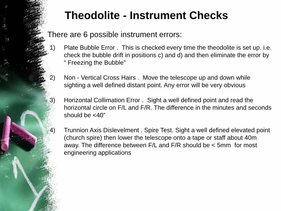
Theodolite - Instrument ChecksThere are 6 possible instrument errors:1) Plate Bubble Error . This is checked every time the theodolite is set up. i.e.
check the bubble drift in positions c) and d) and then eliminate the error by “ Freezing the Bubble”
2) Non - Vertical Cross Hairs . Move the telescope up and down while sighting a well defined distant point. Any error will be very obvious
3) Horizontal Collimation Error . Sight a well defined point and read the horizontal circle on F/L and F/R. The difference in the minutes and seconds should be <40”
4) Trunnion Axis Dislevelment . Spire Test. Sight a well defined elevated point (church spire) then lower the telescope onto a tape or staff about 40m away. The difference between F/L and F/R should be < 5mm for most engineering applications
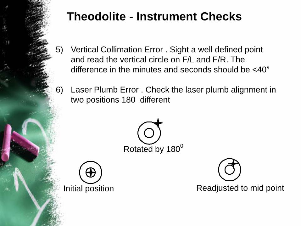
5) Vertical Collimation Error . Sight a well defined point and read the vertical circle on F/L and F/R. The difference in the minutes and seconds should be <40”
6) Laser Plumb Error . Check the laser plumb alignment in two positions 180 different
Initial position
Rotated by 1800
Readjusted to mid point
Theodolite - Instrument Checks
Tribrachs
Tribrachs
Tribrachs
Prism
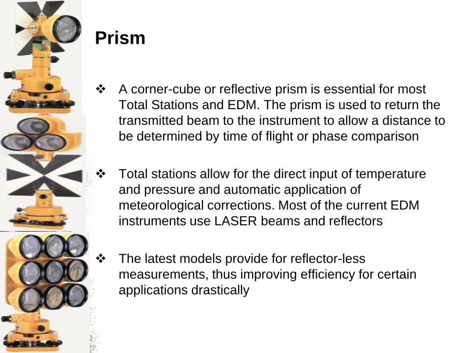
A corner-cube or reflective prism is essential for most Total Stations and EDM. The prism is used to return the transmitted beam to the instrument to allow a distance to be determined by time of flight or phase comparison
Total stations allow for the direct input of temperature and pressure and automatic application of meteorological corrections. Most of the current EDM instruments use LASER beams and reflectors
The latest models provide for reflector-less measurements, thus improving efficiency for certain applications drastically
Routine Care of Theodolite/Total Station
Routine Care of Theodolite/Total Station
Before making the first set up of the day, visually inspect the instrument for damage. Check the machined surfaces and the polished faces of the lenses and mirrors. Try the clamps and motions for smooth operation
Clean the exterior of the instrument frequently. Any accumulation of dirt and dust can scratch the machined or polished surfaces and cause friction or sticking in the motions. Remove dirt and dust with a clean, soft cloth or with a brush. Clean non-optical parts with a soft cloth or clean chamois
Clean the external surfaces of lenses with a fine lens brush and, if necessary, use a dry lens tissue. Do not use silicone-treated tissues because they can damage coated optics. The lens may be moistened before wiping it, but do not use liquids for cleaning. Do not loosen or attempt to clean the internal surfaces of any lens
After an instrument has been used in damp or cold situation, use special precautions to prevent condensation of moisture inside the instrument. If the instrument is used in cold weather, leave it in the carrying case in the vehicle during non-working periods rather take it into a heated room. If you store the instrument in a heated room overnight, remove it from the carrying case. If the instrument is wet, bring it into a warm, dry room, remove it from its case and leave it at room temperature to dry it
Vehicular Transport
Transport and store instrument in positions that are consistent with the carrying case design. For example, total station should be carried and stored in their correct position. Many instrument cases indicate the position in which they should be transported
Treat tribrachs, prism and tripods with care. Carry them in their shipping cases or cushion them with firm polyfoamor excelsior-filled cases to protect the from jolting or vibrating excessively
Casing and Uncasing
Before removing an instrument, study the way it is placed and secured in the case. Place it in the same position when you return it to the case. In removing the instrument from the case, carefully grip it with both hands, but do not grip the vertical circle standard or where pressure will be exerted or tubular or circular level vials
Sources of Error in Total Station Work
Instrument Errors
• Plate bubble out of adjustment• Horizontal axis not perpendicular to vertical
axis• Axis of sight not perpendicular to horizontal
axis• Vertical circular index error• Eccentricity of centres• Circle graduation errors• Errors caused by peripheral equipment
Sources of Error in Total Station Work
Natural Errors
• Wind• Temperature effects• Refraction• Tripod settlement
Sources of Error in total Station Work
Personal Errors
• Instrument not set up exactly over point• Bubbles not centred perfectly• Improper use of clamps and tangent
screws• Poor focusing• Overly careful sights• Careless plumbing and placement of rod
Mistakes
Some common mistakes in angle measurement work are:
• Sighting on, or setting up over the wrong point
• Calling out or recording an incorrect value• Improper focusing of the eyepiece and
objective lenses of the instrument• Partiality on the tripod, or placing a hand on
the instrument when pointing or taking readings
Question
List three (3) major features that make the difference among Transit, Electronic Distance Measurement and Total Station

T h a n k Y o u & Q u e s t i o n a n d A n s w e r